instrument flight manual (00-80t-112) - public intelligence flight manual (00-80t-112) - public...
TRANSCRIPT

NATOPSINSTRUMENT FLIGHT MANUAL
15 NOVEMBER 20061 (Reverse Blank)
NAVAIR 00-80T-112
THIS PUBLICATION SUPERSEDES NAVAIR 00-80T-112DATED 15 OCTOBER 2002.
DISTRIBUTION STATEMENT C — Distribution authorized to U.S.Government agencies only and their contractors to protect publicationsrequired for official use or for administrative or operational purposes only(15 November 2006). Other requests for this document shall be referred toCommander, Naval Air Systems Command (PMA-251), RADM William AMoffett Bldg, 47123 Buse Rd, Bldg 2272, Patuxent River, MD 20670-1547.
DESTRUCTION NOTICE — For unclassified, limited documents, destroy byany method that will prevent disclosure of contents or reconstruction of thedocument.
ISSUED BY AUTHORITY OF THE CHIEF OF NAVAL OPERATIONS ANDUNDER THE DIRECTION OF THE COMMANDER,
NAVAL AIR SYSTEMS COMMAND.
3
4
5
6
7
INTRODUCTION
PHYSIOLOGY OFINSTRUMENT FLIGHT
AIRCRAFT FLIGHT/NAVIGATIONAL INSTR
ATTITUDEINSTRUMENT FLIGHT
NAVAIDS/FACILITIES &PROCEDURES
INSTRUMENTFLIGHT
INDOCTRINATION &FLIGHT EVALUATION
2
8
1
APPENDICES& INDEX
METEOROLOGY
0800LP1063562

A1−H60BB−NFM−000
ORIGINAL1/(2 blank)

NAVAIR 00-80T-112
ORIGINAL3/(4 blank)
DEPARTMENT OF THE NAVYNAVAL AIR SYSTEMS COMMAND
RADM WILLIAM A. MOFFETT BUILDING 47123 BUSE ROAD, BLDG 2272
PATUXENT RIVER, MD 20670-1547
15 November 2006
LETTER OF PROMULGATION
1. The Naval Air Training and Operating Procedures Standardization (NATOPS) Program is apositive approach toward improving combat readiness and achieving a substantial reduction in theaircraft mishap rate. Standardization, based on professional knowledge and experience, provides thebasis for development of an efficient and sound operational procedure. The standardization programis not planned to stifle individual initiative, but rather to aid the Commanding Officer in increasingthe unit’s combat potential without reducing command prestige or responsibility.
2. This manual standardizes ground and flight procedures but does not include tactical doctrine.Compliance with the stipulated manual requirements and procedures is mandatory except asauthorized herein. In order to remain effective, NATOPS must be dynamic and stimulate rather thansuppress individual thinking. Since aviation is a continuing, progressive profession, it is bothdesirable and necessary that new ideas and new techniques be expeditiously evaluated andincorporated if proven to be sound. To this end, Commanding Officers of aviation units areauthorized to modify procedures contained herein, in accordance with the waiver provisionsestablished by OPNAV Instruction 3710.7, for the purpose of assessing new ideas prior to initiatingrecommendations for permanent changes. This manual is prepared and kept current by the users inorder to achieve maximum readiness and safety in the most efficient and economical manner. Shouldconflict exist between the training and operating procedures found in this manual and those foundin other publications, this manual will govern.
3. Checklists and other pertinent extracts from this publication necessary to normal operations andtraining should be made and carried for use in naval aircraft.
S. R. EASTBURGCaptain, United States NavyBy direction ofCommander, Naval Air Systems Command

NAVAIR 00-80T-112
ORIGINAL1/(2 blank)

NAVAIR 00-80T-112
ORIGINAL5/(6 blank)
INTERIM CHANGE SUMMARY
The following Interim Changes have been canceled or previously incorporated into this manual.
INTERIMCHANGE
NUMBER(S) REMARKS/PURPOSE
The following Interim Changes have been incorporated into this Change/Revision.
INTERIMCHANGE
NUMBER(S) REMARKS/PURPOSE
Interim Changes Outstanding — To be maintained by the custodian of this manual.
INTERIMCHANGE
NUMBER(S)ORIGINATOR/DATE
(or DATE/TIME GROUP)PAGES
AFFECTED REMARKS/PURPOSE

NAVAIR 00-80T-112
ORIGINAL1/(2 blank)

NAVAIR 00-80T-112
ORIGINAL7/(8 blank)
RECORD OF CHANGES
Change No. andDate of Change
Date ofEntry
Page Count Verified by(Signature)

NAVAIR 00-80T-112
ORIGINAL1/(2 blank)

NAVAIR 00-80T-112
ORIGINAL9
NATOPS INSTRUMENT FLIGHT MANUALContents
PageNo.
PART I — INTRODUCTION
CHAPTER 1 — INTRODUCTION
1.1 PURPOSE 1-1 . . . . . . . . . . . . . . . . . . . . . . . . . . . . . . . . . . . . . . . . . . . . . . . . . . . . . . . . . . . . .
1.2 SCOPE 1-1 . . . . . . . . . . . . . . . . . . . . . . . . . . . . . . . . . . . . . . . . . . . . . . . . . . . . . . . . . . . . . . .
1.3 GENERAL 1-1 . . . . . . . . . . . . . . . . . . . . . . . . . . . . . . . . . . . . . . . . . . . . . . . . . . . . . . . . . . . .
1.4 RESPONSIBILITIES 1-1 . . . . . . . . . . . . . . . . . . . . . . . . . . . . . . . . . . . . . . . . . . . . . . . . . . . . 1.4.1 NATOPS Advisory Group 1-1 . . . . . . . . . . . . . . . . . . . . . . . . . . . . . . . . . . . . . . . . . . . . . . . . . 1.4.2 NATOPS Cognizant Command 1-1 . . . . . . . . . . . . . . . . . . . . . . . . . . . . . . . . . . . . . . . . . . . . . 1.4.3 NATOPS Model Manager 1-2 . . . . . . . . . . . . . . . . . . . . . . . . . . . . . . . . . . . . . . . . . . . . . . . . . 1.4.4 Commanding Officers 1-2 . . . . . . . . . . . . . . . . . . . . . . . . . . . . . . . . . . . . . . . . . . . . . . . . . . . .
1.5 TRAINING 1-2 . . . . . . . . . . . . . . . . . . . . . . . . . . . . . . . . . . . . . . . . . . . . . . . . . . . . . . . . . . . .
1.6 WAIVERS 1-2 . . . . . . . . . . . . . . . . . . . . . . . . . . . . . . . . . . . . . . . . . . . . . . . . . . . . . . . . . . . . .
PART II — METEOROLOGY
CHAPTER 2 — CONCEPT
2.1 METEOROLOGY FOR NAVAL AVIATORS 2-1 . . . . . . . . . . . . . . . . . . . . . . . . . . . . . . . . .
CHAPTER 3 — AIRMASSES
3.1 CONCEPT 3-1 . . . . . . . . . . . . . . . . . . . . . . . . . . . . . . . . . . . . . . . . . . . . . . . . . . . . . . . . . . . . . 3.1.1 Airmass Classification 3-1 . . . . . . . . . . . . . . . . . . . . . . . . . . . . . . . . . . . . . . . . . . . . . . . . . . . . 3.1.2 Airmass Development 3-1 . . . . . . . . . . . . . . . . . . . . . . . . . . . . . . . . . . . . . . . . . . . . . . . . . . . . 3.1.3 Airmass Modification 3-1 . . . . . . . . . . . . . . . . . . . . . . . . . . . . . . . . . . . . . . . . . . . . . . . . . . . . 3.1.4 Airmass Weather 3-2 . . . . . . . . . . . . . . . . . . . . . . . . . . . . . . . . . . . . . . . . . . . . . . . . . . . . . . . .
CHAPTER 4 — FRONTS
4.1 INTRODUCTION 4-1 . . . . . . . . . . . . . . . . . . . . . . . . . . . . . . . . . . . . . . . . . . . . . . . . . . . . . . .
4.2 RELATION OF FRONTS TO CYCLONES 4-1 . . . . . . . . . . . . . . . . . . . . . . . . . . . . . . . . . .
4.3 RELATION OF FRONTS TO AIRMASSES 4-1 . . . . . . . . . . . . . . . . . . . . . . . . . . . . . . . . . . 4.3.1 Cold Fronts 4-1 . . . . . . . . . . . . . . . . . . . . . . . . . . . . . . . . . . . . . . . . . . . . . . . . . . . . . . . . . . . . 4.3.2 Warm Fronts 4-3 . . . . . . . . . . . . . . . . . . . . . . . . . . . . . . . . . . . . . . . . . . . . . . . . . . . . . . . . . . . 4.3.3 Occluded Fronts 4-5 . . . . . . . . . . . . . . . . . . . . . . . . . . . . . . . . . . . . . . . . . . . . . . . . . . . . . . . . 4.3.4 Stationary Fronts 4-5 . . . . . . . . . . . . . . . . . . . . . . . . . . . . . . . . . . . . . . . . . . . . . . . . . . . . . . . .
4.4 PRESSURE AT FRONTS 4-7 . . . . . . . . . . . . . . . . . . . . . . . . . . . . . . . . . . . . . . . . . . . . . . . . .

NAVAIR 00-80T-112
ORIGINAL 10
PageNo.
4.5 FRONTAL MOVEMENT 4-7 . . . . . . . . . . . . . . . . . . . . . . . . . . . . . . . . . . . . . . . . . . . . . . . . . 4.5.1 Speed 4-7 . . . . . . . . . . . . . . . . . . . . . . . . . . . . . . . . . . . . . . . . . . . . . . . . . . . . . . . . . . . . . . . . . 4.5.2 Modifications 4-7 . . . . . . . . . . . . . . . . . . . . . . . . . . . . . . . . . . . . . . . . . . . . . . . . . . . . . . . . . .
CHAPTER 5 — TROPICAL METEOROLOGY
5.1 INTRODUCTION 5-1 . . . . . . . . . . . . . . . . . . . . . . . . . . . . . . . . . . . . . . . . . . . . . . . . . . . . . . .
5.2 TROPICAL WAVES 5-1 . . . . . . . . . . . . . . . . . . . . . . . . . . . . . . . . . . . . . . . . . . . . . . . . . . . . . 5.2.1 Stable Wave 5-1 . . . . . . . . . . . . . . . . . . . . . . . . . . . . . . . . . . . . . . . . . . . . . . . . . . . . . . . . . . . . 5.2.2 Neutral Wave 5-1 . . . . . . . . . . . . . . . . . . . . . . . . . . . . . . . . . . . . . . . . . . . . . . . . . . . . . . . . . . . 5.2.3 Unstable Wave 5-1 . . . . . . . . . . . . . . . . . . . . . . . . . . . . . . . . . . . . . . . . . . . . . . . . . . . . . . . . . .
5.3 INTERTROPICAL CONVERGENCE ZONE 5-2 . . . . . . . . . . . . . . . . . . . . . . . . . . . . . . . . .
5.4 CONVERGENCE ZONES 5-2 . . . . . . . . . . . . . . . . . . . . . . . . . . . . . . . . . . . . . . . . . . . . . . . .
5.5 SHEAR LINES 5-3 . . . . . . . . . . . . . . . . . . . . . . . . . . . . . . . . . . . . . . . . . . . . . . . . . . . . . . . . .
CHAPTER 6 — WEATHER HAZARDS TO FLIGHT
6.1 THUNDERSTORMS 6-1 . . . . . . . . . . . . . . . . . . . . . . . . . . . . . . . . . . . . . . . . . . . . . . . . . . . . 6.1.1 Thunderstorm Development 6-1 . . . . . . . . . . . . . . . . . . . . . . . . . . . . . . . . . . . . . . . . . . . . . . . 6.1.2 Thunderstorm Weather 6-3 . . . . . . . . . . . . . . . . . . . . . . . . . . . . . . . . . . . . . . . . . . . . . . . . . . . 6.1.3 Thunderstorm Classification 6-3 . . . . . . . . . . . . . . . . . . . . . . . . . . . . . . . . . . . . . . . . . . . . . . .
6.2 SQUALL LINES 6-4 . . . . . . . . . . . . . . . . . . . . . . . . . . . . . . . . . . . . . . . . . . . . . . . . . . . . . . . .
6.3 TORNADOES AND WATERSPOUTS 6-4 . . . . . . . . . . . . . . . . . . . . . . . . . . . . . . . . . . . . . .
6.4 TURBULENCE 6-6 . . . . . . . . . . . . . . . . . . . . . . . . . . . . . . . . . . . . . . . . . . . . . . . . . . . . . . . . 6.4.1 Mountainous Terrain 6-6 . . . . . . . . . . . . . . . . . . . . . . . . . . . . . . . . . . . . . . . . . . . . . . . . . . . . . 6.4.2 Clear-Air Turbulence 6-7 . . . . . . . . . . . . . . . . . . . . . . . . . . . . . . . . . . . . . . . . . . . . . . . . . . . . .
6.5 FOG 6-7 . . . . . . . . . . . . . . . . . . . . . . . . . . . . . . . . . . . . . . . . . . . . . . . . . . . . . . . . . . . . . . . . . . 6.5.1 Radiation Fog 6-7 . . . . . . . . . . . . . . . . . . . . . . . . . . . . . . . . . . . . . . . . . . . . . . . . . . . . . . . . . . 6.5.2 Advection Fog 6-8 . . . . . . . . . . . . . . . . . . . . . . . . . . . . . . . . . . . . . . . . . . . . . . . . . . . . . . . . . . 6.5.3 Frontal Fog 6-8 . . . . . . . . . . . . . . . . . . . . . . . . . . . . . . . . . . . . . . . . . . . . . . . . . . . . . . . . . . . . 6.5.4 Arctic Fog 6-8 . . . . . . . . . . . . . . . . . . . . . . . . . . . . . . . . . . . . . . . . . . . . . . . . . . . . . . . . . . . . .
6.6 AIRCRAFT ICING 6-9 . . . . . . . . . . . . . . . . . . . . . . . . . . . . . . . . . . . . . . . . . . . . . . . . . . . . . . 6.6.1 Structural Icing 6-9 . . . . . . . . . . . . . . . . . . . . . . . . . . . . . . . . . . . . . . . . . . . . . . . . . . . . . . . . .
6.7 STRUCTURAL DEICING 6-10 . . . . . . . . . . . . . . . . . . . . . . . . . . . . . . . . . . . . . . . . . . . . . . . 6.7.1 Airfoil 6-10 . . . . . . . . . . . . . . . . . . . . . . . . . . . . . . . . . . . . . . . . . . . . . . . . . . . . . . . . . . . . . . . 6.7.2 Propeller 6-10 . . . . . . . . . . . . . . . . . . . . . . . . . . . . . . . . . . . . . . . . . . . . . . . . . . . . . . . . . . . . . 6.7.3 Pitot-Static/Angle of Attack (AOA) Systems 6-11 . . . . . . . . . . . . . . . . . . . . . . . . . . . . . . . . . 6.7.4 Structural Icing Precautions 6-11 . . . . . . . . . . . . . . . . . . . . . . . . . . . . . . . . . . . . . . . . . . . . . . 6.7.5 Aircraft Engine Icing 6-11 . . . . . . . . . . . . . . . . . . . . . . . . . . . . . . . . . . . . . . . . . . . . . . . . . . . .
6.8 LOW-LEVEL WINDSHEAR 6-11 . . . . . . . . . . . . . . . . . . . . . . . . . . . . . . . . . . . . . . . . . . . . . 6.8.1 Convective Windshear 6-12 . . . . . . . . . . . . . . . . . . . . . . . . . . . . . . . . . . . . . . . . . . . . . . . . . . . 6.8.2 Nonconvective Windshear 6-12 . . . . . . . . . . . . . . . . . . . . . . . . . . . . . . . . . . . . . . . . . . . . . . . .
6.9 MICROBURSTS 6-12 . . . . . . . . . . . . . . . . . . . . . . . . . . . . . . . . . . . . . . . . . . . . . . . . . . . . . . .

NAVAIR 00-80T-112
ORIGINAL11
PageNo.
PART III — PHYSIOLOGY OF INSTRUMENT FLIGHT
CHAPTER 7 — INTRODUCTION TO INSTRUMENT FLIGHT PHYSIOLOGY
7.1 GENERAL 7-1 . . . . . . . . . . . . . . . . . . . . . . . . . . . . . . . . . . . . . . . . . . . . . . . . . . . . . . . . . . . .
7.2 YOUR SENSES 7-1 . . . . . . . . . . . . . . . . . . . . . . . . . . . . . . . . . . . . . . . . . . . . . . . . . . . . . . . . 7.2.1 Motion (Inner Ear) 7-1 . . . . . . . . . . . . . . . . . . . . . . . . . . . . . . . . . . . . . . . . . . . . . . . . . . . . . . . 7.2.2 Semicircular Canals 7-1 . . . . . . . . . . . . . . . . . . . . . . . . . . . . . . . . . . . . . . . . . . . . . . . . . . . . . . 7.2.3 Otolith Organs 7-4 . . . . . . . . . . . . . . . . . . . . . . . . . . . . . . . . . . . . . . . . . . . . . . . . . . . . . . . . . . 7.2.4 Postural (Seat of the Pants) 7-4 . . . . . . . . . . . . . . . . . . . . . . . . . . . . . . . . . . . . . . . . . . . . . . . . 7.2.5 Sight 7-5 . . . . . . . . . . . . . . . . . . . . . . . . . . . . . . . . . . . . . . . . . . . . . . . . . . . . . . . . . . . . . . . . .
CHAPTER 8 — SPATIAL DISORIENTATION
8.1 FALSE PERCEPTION (GENERAL) 8-1 . . . . . . . . . . . . . . . . . . . . . . . . . . . . . . . . . . . . . . . . 8.1.1 Illusions: Primarily Inner Ear 8-1 . . . . . . . . . . . . . . . . . . . . . . . . . . . . . . . . . . . . . . . . . . . . . . 8.1.2 Visual Illusions and Problems 8-9 . . . . . . . . . . . . . . . . . . . . . . . . . . . . . . . . . . . . . . . . . . . . . . 8.1.3 False Perceptions During Helicopter Flights 8-10 . . . . . . . . . . . . . . . . . . . . . . . . . . . . . . . . .
8.2 SPATIAL MISORIENTATION 8-12 . . . . . . . . . . . . . . . . . . . . . . . . . . . . . . . . . . . . . . . . . . . .
CHAPTER 9 — FACTORS THAT INCREASE THE POTENTIAL FOR SPATIAL DISORIENTATION
9.1 GENERAL 9-1 . . . . . . . . . . . . . . . . . . . . . . . . . . . . . . . . . . . . . . . . . . . . . . . . . . . . . . . . . . . .
9.2 PERSONAL FACTORS 9-1 . . . . . . . . . . . . . . . . . . . . . . . . . . . . . . . . . . . . . . . . . . . . . . . . . .
9.3 ENVIRONMENTAL FACTORS 9-1 . . . . . . . . . . . . . . . . . . . . . . . . . . . . . . . . . . . . . . . . . . .
9.4 FACTORS RELATED TO TYPE OR PHASE OF FLIGHT 9-1 . . . . . . . . . . . . . . . . . . . . . . 9.4.1 Takeoff and Landing Phases 9-1 . . . . . . . . . . . . . . . . . . . . . . . . . . . . . . . . . . . . . . . . . . . . . . . 9.4.2 ACM or Air-to-Ground Ordnance Deliveries 9-2 . . . . . . . . . . . . . . . . . . . . . . . . . . . . . . . . . . 9.4.3 Formation Flight 9-2 . . . . . . . . . . . . . . . . . . . . . . . . . . . . . . . . . . . . . . . . . . . . . . . . . . . . . . . .
CHAPTER 10 — MEDICATIONS, ALCOHOL, AND NUTRITION
10.1 GENERAL 10-1 . . . . . . . . . . . . . . . . . . . . . . . . . . . . . . . . . . . . . . . . . . . . . . . . . . . . . . . . . . .
10.2 NUTRITION 10-1 . . . . . . . . . . . . . . . . . . . . . . . . . . . . . . . . . . . . . . . . . . . . . . . . . . . . . . . . . .
10.3 EXERCISE 10-1 . . . . . . . . . . . . . . . . . . . . . . . . . . . . . . . . . . . . . . . . . . . . . . . . . . . . . . . . . . .
10.4 DRUGS 10-1 . . . . . . . . . . . . . . . . . . . . . . . . . . . . . . . . . . . . . . . . . . . . . . . . . . . . . . . . . . . . . .

NAVAIR 00-80T-112
ORIGINAL 12
PageNo.
10.5 ILLNESS 10-2 . . . . . . . . . . . . . . . . . . . . . . . . . . . . . . . . . . . . . . . . . . . . . . . . . . . . . . . . . . . . .
10.6 DENTAL CARE 10-2 . . . . . . . . . . . . . . . . . . . . . . . . . . . . . . . . . . . . . . . . . . . . . . . . . . . . . . .
10.7 IMMUNIZATION/INJECTIONS 10-2 . . . . . . . . . . . . . . . . . . . . . . . . . . . . . . . . . . . . . . . . . .
10.8 BLOOD DONATION 10-2 . . . . . . . . . . . . . . . . . . . . . . . . . . . . . . . . . . . . . . . . . . . . . . . . . . .
CHAPTER 11 — PREVENTION OF SPATIAL DISORIENTATION
11.1 GENERAL 11-1 . . . . . . . . . . . . . . . . . . . . . . . . . . . . . . . . . . . . . . . . . . . . . . . . . . . . . . . . . . .
11.2 TRAINING 11-1 . . . . . . . . . . . . . . . . . . . . . . . . . . . . . . . . . . . . . . . . . . . . . . . . . . . . . . . . . . . 11.2.1 Sensation of Climbing During a Turn 11-1 . . . . . . . . . . . . . . . . . . . . . . . . . . . . . . . . . . . . . . . 11.2.2 Sensation of Diving During Recovery From a Turn 11-2 . . . . . . . . . . . . . . . . . . . . . . . . . . . . 11.2.3 False Sensations of Tilting to Right or Left 11-2 . . . . . . . . . . . . . . . . . . . . . . . . . . . . . . . . . . 11.2.4 False Sensation of Reversal of Motion 11-2 . . . . . . . . . . . . . . . . . . . . . . . . . . . . . . . . . . . . . . 11.2.5 Sensation of Diving or Rolling Beyond the Vertical Plane 11-2 . . . . . . . . . . . . . . . . . . . . . . . 11.2.6 Sensation of Climbing During Straight-and-Level Flight 11-2 . . . . . . . . . . . . . . . . . . . . . . . .
11.3 EXPERIENCE 11-3 . . . . . . . . . . . . . . . . . . . . . . . . . . . . . . . . . . . . . . . . . . . . . . . . . . . . . . . .
CHAPTER 12 — OVERCOMING SPATIAL DISORIENTATION
12.1 GENERAL 12-1 . . . . . . . . . . . . . . . . . . . . . . . . . . . . . . . . . . . . . . . . . . . . . . . . . . . . . . . . . . .
12.2 SINGLE-SEAT AIRCRAFT 12-1 . . . . . . . . . . . . . . . . . . . . . . . . . . . . . . . . . . . . . . . . . . . . . .
12.3 DUAL-SEAT AIRCRAFT 12-2 . . . . . . . . . . . . . . . . . . . . . . . . . . . . . . . . . . . . . . . . . . . . . . .
12.4 MULTICREWED AIRCRAFT 12-2 . . . . . . . . . . . . . . . . . . . . . . . . . . . . . . . . . . . . . . . . . . . .
12.5 FORMATION FLIGHTS IN NIGHT OR WEATHER 12-2 . . . . . . . . . . . . . . . . . . . . . . . . . .
PART IV — AIRCRAFT FLIGHT/NAVIGATIONAL INSTRUMENTATION
CHAPTER 13 — INTRODUCTION TO AIRCRAFT FLIGHT INSTRUMENTS
13.1 GENERAL 13-1 . . . . . . . . . . . . . . . . . . . . . . . . . . . . . . . . . . . . . . . . . . . . . . . . . . . . . . . . . . .
CHAPTER 14 — ATTITUDE INSTRUMENTS
14.1 GENERAL 14-1 . . . . . . . . . . . . . . . . . . . . . . . . . . . . . . . . . . . . . . . . . . . . . . . . . . . . . . . . . . .
14.2 HEADS-UP DISPLAY 14-1 . . . . . . . . . . . . . . . . . . . . . . . . . . . . . . . . . . . . . . . . . . . . . . . . . . 14.2.1 HUD Limitations 14-1 . . . . . . . . . . . . . . . . . . . . . . . . . . . . . . . . . . . . . . . . . . . . . . . . . . . . . . . 14.2.2 Global Orientation 14-1 . . . . . . . . . . . . . . . . . . . . . . . . . . . . . . . . . . . . . . . . . . . . . . . . . . . . . . 14.2.3 HUD Field of View 14-3 . . . . . . . . . . . . . . . . . . . . . . . . . . . . . . . . . . . . . . . . . . . . . . . . . . . . . 14.2.4 Conventional Cross-Check 14-3 . . . . . . . . . . . . . . . . . . . . . . . . . . . . . . . . . . . . . . . . . . . . . . .

NAVAIR 00-80T-112
ORIGINAL13
PageNo.
CHAPTER 15 — PERFORMANCE INSTRUMENTS
15.1 COMPASSES 15-1 . . . . . . . . . . . . . . . . . . . . . . . . . . . . . . . . . . . . . . . . . . . . . . . . . . . . . . . . . 15.1.1 Standby Magnetic Compass 15-1 . . . . . . . . . . . . . . . . . . . . . . . . . . . . . . . . . . . . . . . . . . . . . . 15.1.2 Variation 15-1 . . . . . . . . . . . . . . . . . . . . . . . . . . . . . . . . . . . . . . . . . . . . . . . . . . . . . . . . . . . . . 15.1.3 Deviation 15-3 . . . . . . . . . . . . . . . . . . . . . . . . . . . . . . . . . . . . . . . . . . . . . . . . . . . . . . . . . . . . . 15.1.4 Magnetic Dip 15-3 . . . . . . . . . . . . . . . . . . . . . . . . . . . . . . . . . . . . . . . . . . . . . . . . . . . . . . . . . . 15.1.5 Acceleration Error 15-4 . . . . . . . . . . . . . . . . . . . . . . . . . . . . . . . . . . . . . . . . . . . . . . . . . . . . . . 15.1.6 Oscillation Error 15-4 . . . . . . . . . . . . . . . . . . . . . . . . . . . . . . . . . . . . . . . . . . . . . . . . . . . . . . .
15.2 AIRSPEED INDICATOR 15-4 . . . . . . . . . . . . . . . . . . . . . . . . . . . . . . . . . . . . . . . . . . . . . . . .
15.3 VERTICAL SPEED INDICATOR (VSI/VVI) 15-4 . . . . . . . . . . . . . . . . . . . . . . . . . . . . . . . . 15.3.1 VSI Error 15-4 . . . . . . . . . . . . . . . . . . . . . . . . . . . . . . . . . . . . . . . . . . . . . . . . . . . . . . . . . . . . . 15.3.2 Dial Calibration 15-4 . . . . . . . . . . . . . . . . . . . . . . . . . . . . . . . . . . . . . . . . . . . . . . . . . . . . . . . .
15.4 TURN AND SLIP INDICATOR 15-4 . . . . . . . . . . . . . . . . . . . . . . . . . . . . . . . . . . . . . . . . . . . 15.4.1 Turn Indicator (Needle) 15-6 . . . . . . . . . . . . . . . . . . . . . . . . . . . . . . . . . . . . . . . . . . . . . . . . . . 15.4.2 Slip Indicator (Ball) 15-6 . . . . . . . . . . . . . . . . . . . . . . . . . . . . . . . . . . . . . . . . . . . . . . . . . . . . .
15.5 ANGLE OF ATTACK INDICATOR 15-8 . . . . . . . . . . . . . . . . . . . . . . . . . . . . . . . . . . . . . . .
15.6 HOVER INDICATOR 15-8 . . . . . . . . . . . . . . . . . . . . . . . . . . . . . . . . . . . . . . . . . . . . . . . . . . .
15.7 CLOCK 15-8 . . . . . . . . . . . . . . . . . . . . . . . . . . . . . . . . . . . . . . . . . . . . . . . . . . . . . . . . . . . . . .
15.8 OUTSIDE AIR TEMPERATURE GAUGE 15-8 . . . . . . . . . . . . . . . . . . . . . . . . . . . . . . . . . .
CHAPTER 16 — POSITION INSTRUMENTS
16.1 ALTIMETERS 16-1 . . . . . . . . . . . . . . . . . . . . . . . . . . . . . . . . . . . . . . . . . . . . . . . . . . . . . . . . 16.1.1 Pressure Altimeter 16-1 . . . . . . . . . . . . . . . . . . . . . . . . . . . . . . . . . . . . . . . . . . . . . . . . . . . . . . 16.1.2 Radio/Radar Altimeters 16-4 . . . . . . . . . . . . . . . . . . . . . . . . . . . . . . . . . . . . . . . . . . . . . . . . . .
16.2 RANGE INDICATOR 16-4 . . . . . . . . . . . . . . . . . . . . . . . . . . . . . . . . . . . . . . . . . . . . . . . . . . .
16.3 BEARING INDICATORS 16-6 . . . . . . . . . . . . . . . . . . . . . . . . . . . . . . . . . . . . . . . . . . . . . . . 16.3.1 Radio Magnetic Indicator (RMI) 16-6 . . . . . . . . . . . . . . . . . . . . . . . . . . . . . . . . . . . . . . . . . . . 16.3.2 Bearing-Distance-Heading Indicator (BDHI) 16-6 . . . . . . . . . . . . . . . . . . . . . . . . . . . . . . . . . 16.3.3 Horizontal Situation Indicator (HSI) 16-6 . . . . . . . . . . . . . . . . . . . . . . . . . . . . . . . . . . . . . . . .
16.4 COURSE INDICATOR 16-10 . . . . . . . . . . . . . . . . . . . . . . . . . . . . . . . . . . . . . . . . . . . . . . . . . 16.4.1 VOR/TACAN Display 16-11 . . . . . . . . . . . . . . . . . . . . . . . . . . . . . . . . . . . . . . . . . . . . . . . . . 16.4.2 ILS Display 16-11 . . . . . . . . . . . . . . . . . . . . . . . . . . . . . . . . . . . . . . . . . . . . . . . . . . . . . . . . . .
16.5 FLIGHT DIRECTOR SYSTEM 16-12 . . . . . . . . . . . . . . . . . . . . . . . . . . . . . . . . . . . . . . . . . .
16.6 OTHER POSITION INSTRUMENTS 16-12 . . . . . . . . . . . . . . . . . . . . . . . . . . . . . . . . . . . . .

NAVAIR 00-80T-112
ORIGINAL 14
PageNo.
PART V — ATTITUDE INSTRUMENT FLIGHT
CHAPTER 17 — ATTITUDE INSTRUMENT FLYING
17.1 GENERAL 17-1 . . . . . . . . . . . . . . . . . . . . . . . . . . . . . . . . . . . . . . . . . . . . . . . . . . . . . . . . . . .
17.2 AIRCRAFT CONTROL 17-1 . . . . . . . . . . . . . . . . . . . . . . . . . . . . . . . . . . . . . . . . . . . . . . . . . 17.2.1 Attitude Control 17-2 . . . . . . . . . . . . . . . . . . . . . . . . . . . . . . . . . . . . . . . . . . . . . . . . . . . . . . .
17.3 INSTRUMENT GROUPINGS 17-4 . . . . . . . . . . . . . . . . . . . . . . . . . . . . . . . . . . . . . . . . . . . . 17.3.1 Control Instruments 17-4 . . . . . . . . . . . . . . . . . . . . . . . . . . . . . . . . . . . . . . . . . . . . . . . . . . . . . 17.3.2 Performance Instruments 17-4 . . . . . . . . . . . . . . . . . . . . . . . . . . . . . . . . . . . . . . . . . . . . . . . . . 17.3.3 Position Instruments 17-4 . . . . . . . . . . . . . . . . . . . . . . . . . . . . . . . . . . . . . . . . . . . . . . . . . . . . 17.3.4 Instrument Scan 17-4 . . . . . . . . . . . . . . . . . . . . . . . . . . . . . . . . . . . . . . . . . . . . . . . . . . . . . . . . 17.3.5 Functions of Instruments — Full Panel Scan 17-4 . . . . . . . . . . . . . . . . . . . . . . . . . . . . . . . . . 17.3.6 Scan Technique 17-6 . . . . . . . . . . . . . . . . . . . . . . . . . . . . . . . . . . . . . . . . . . . . . . . . . . . . . . . . 17.3.7 Scan Analysis 17-7 . . . . . . . . . . . . . . . . . . . . . . . . . . . . . . . . . . . . . . . . . . . . . . . . . . . . . . . . . 17.3.8 Use of Angle of Attack 17-7 . . . . . . . . . . . . . . . . . . . . . . . . . . . . . . . . . . . . . . . . . . . . . . . . . .
17.4 AIRCRAFT TRIM 17-9 . . . . . . . . . . . . . . . . . . . . . . . . . . . . . . . . . . . . . . . . . . . . . . . . . . . . .
17.5 INSTRUMENT HOVERING 17-10 . . . . . . . . . . . . . . . . . . . . . . . . . . . . . . . . . . . . . . . . . . . .
CHAPTER 18 — INSTRUMENT FLIGHT MANEUVERS
18.1 APPLICATION 18-1 . . . . . . . . . . . . . . . . . . . . . . . . . . . . . . . . . . . . . . . . . . . . . . . . . . . . . . . . 18.1.1 Planning 18-1 . . . . . . . . . . . . . . . . . . . . . . . . . . . . . . . . . . . . . . . . . . . . . . . . . . . . . . . . . . . . . .
18.2 INSTRUMENT TAKEOFF (ITO) 18-2 . . . . . . . . . . . . . . . . . . . . . . . . . . . . . . . . . . . . . . . . . 18.2.1 Pretakeoff Procedures 18-2 . . . . . . . . . . . . . . . . . . . . . . . . . . . . . . . . . . . . . . . . . . . . . . . . . . .
18.3 STRAIGHT-AND-LEVEL FLIGHT 18-4 . . . . . . . . . . . . . . . . . . . . . . . . . . . . . . . . . . . . . . . 18.3.1 Maintaining a Desired Altitude 18-4 . . . . . . . . . . . . . . . . . . . . . . . . . . . . . . . . . . . . . . . . . . . . 18.3.2 Level Turns 18-8 . . . . . . . . . . . . . . . . . . . . . . . . . . . . . . . . . . . . . . . . . . . . . . . . . . . . . . . . . . .
18.4 CLIMBS AND DESCENT 18-12 . . . . . . . . . . . . . . . . . . . . . . . . . . . . . . . . . . . . . . . . . . . . . . 18.4.1 Constant Airspeed Climbs and Descents 18-12 . . . . . . . . . . . . . . . . . . . . . . . . . . . . . . . . . . . 18.4.2 Constant-Rate Climbs and Descents 18-14 . . . . . . . . . . . . . . . . . . . . . . . . . . . . . . . . . . . . . . .
18.5 ROTARY-WING INSTRUMENT FLYING 18-15 . . . . . . . . . . . . . . . . . . . . . . . . . . . . . . . . . 18.5.1 Attitude Stabilization 18-15 . . . . . . . . . . . . . . . . . . . . . . . . . . . . . . . . . . . . . . . . . . . . . . . . . . 18.5.2 Yaw Stabilization 18-16 . . . . . . . . . . . . . . . . . . . . . . . . . . . . . . . . . . . . . . . . . . . . . . . . . . . . . . 18.5.3 Altitude Stabilization 18-16 . . . . . . . . . . . . . . . . . . . . . . . . . . . . . . . . . . . . . . . . . . . . . . . . . . 18.5.4 Attitude Control 18-16 . . . . . . . . . . . . . . . . . . . . . . . . . . . . . . . . . . . . . . . . . . . . . . . . . . . . . . 18.5.5 Power Control 18-16 . . . . . . . . . . . . . . . . . . . . . . . . . . . . . . . . . . . . . . . . . . . . . . . . . . . . . . . . 18.5.6 Altitude Control 18-16 . . . . . . . . . . . . . . . . . . . . . . . . . . . . . . . . . . . . . . . . . . . . . . . . . . . . . . 18.5.7 Airspeed Control 18-16 . . . . . . . . . . . . . . . . . . . . . . . . . . . . . . . . . . . . . . . . . . . . . . . . . . . . . .
18.6 PARTIAL PANEL FLIGHT 18-17 . . . . . . . . . . . . . . . . . . . . . . . . . . . . . . . . . . . . . . . . . . . . . 18.6.1 Heading Indicator Failure 18-17 . . . . . . . . . . . . . . . . . . . . . . . . . . . . . . . . . . . . . . . . . . . . . . . 18.6.2 Attitude Indicator Failure 18-18 . . . . . . . . . . . . . . . . . . . . . . . . . . . . . . . . . . . . . . . . . . . . . . .

NAVAIR 00-80T-112
ORIGINAL15
PageNo.
CHAPTER 19 — INSTRUMENT PATTERNS AND CONFIDENCE MANEUVERS
19.1 PURPOSE 19-1 . . . . . . . . . . . . . . . . . . . . . . . . . . . . . . . . . . . . . . . . . . . . . . . . . . . . . . . . . . . .
19.2 INSTRUMENT PATTERNS 19-1 . . . . . . . . . . . . . . . . . . . . . . . . . . . . . . . . . . . . . . . . . . . . . .
19.2.1 Vertical S-1, S-2, S-3, S-4 19-1 . . . . . . . . . . . . . . . . . . . . . . . . . . . . . . . . . . . . . . . . . . . . . . . .
19.2.2 Steep Turns 19-4 . . . . . . . . . . . . . . . . . . . . . . . . . . . . . . . . . . . . . . . . . . . . . . . . . . . . . . . . . . . 19.2.3 OSCAR Pattern 19-4 . . . . . . . . . . . . . . . . . . . . . . . . . . . . . . . . . . . . . . . . . . . . . . . . . . . . . . . .
19.2.4 CHARLIE Pattern 19-5 . . . . . . . . . . . . . . . . . . . . . . . . . . . . . . . . . . . . . . . . . . . . . . . . . . . . . .
19.2.5 BRAVO Pattern 19-6 . . . . . . . . . . . . . . . . . . . . . . . . . . . . . . . . . . . . . . . . . . . . . . . . . . . . . . . . 19.2.6 YANKEE Pattern 19-6 . . . . . . . . . . . . . . . . . . . . . . . . . . . . . . . . . . . . . . . . . . . . . . . . . . . . . . .
19.3 CONFIDENCE MANEUVERS 19-7 . . . . . . . . . . . . . . . . . . . . . . . . . . . . . . . . . . . . . . . . . . .
19.3.1 Wingover 19-7 . . . . . . . . . . . . . . . . . . . . . . . . . . . . . . . . . . . . . . . . . . . . . . . . . . . . . . . . . . . . . 19.3.2 Barrel Roll 19-7 . . . . . . . . . . . . . . . . . . . . . . . . . . . . . . . . . . . . . . . . . . . . . . . . . . . . . . . . . . . .
19.3.3 Aileron Roll 19-9 . . . . . . . . . . . . . . . . . . . . . . . . . . . . . . . . . . . . . . . . . . . . . . . . . . . . . . . . . . .
19.3.4 Loops 19-9 . . . . . . . . . . . . . . . . . . . . . . . . . . . . . . . . . . . . . . . . . . . . . . . . . . . . . . . . . . . . . . . . 19.3.5 Immelmann 19-11 . . . . . . . . . . . . . . . . . . . . . . . . . . . . . . . . . . . . . . . . . . . . . . . . . . . . . . . . . .
19.3.6 Half Cuban Eight 19-11 . . . . . . . . . . . . . . . . . . . . . . . . . . . . . . . . . . . . . . . . . . . . . . . . . . . . . .
CHAPTER 20 — UNUSUAL ATTITUDES
20.1 INTRODUCTION 20-1 . . . . . . . . . . . . . . . . . . . . . . . . . . . . . . . . . . . . . . . . . . . . . . . . . . . . . .
20.2 ATTITUDE INTERPRETATION 20-2 . . . . . . . . . . . . . . . . . . . . . . . . . . . . . . . . . . . . . . . . . .
20.3 RECOVERY PROCEDURES 20-2 . . . . . . . . . . . . . . . . . . . . . . . . . . . . . . . . . . . . . . . . . . . . 20.3.1 Nose-High Recovery 20-2 . . . . . . . . . . . . . . . . . . . . . . . . . . . . . . . . . . . . . . . . . . . . . . . . . . . .
20.3.2 Nose-Low Recovery 20-4 . . . . . . . . . . . . . . . . . . . . . . . . . . . . . . . . . . . . . . . . . . . . . . . . . . . .
20.3.3 Partial Panel Unusual Attitudes 20-4 . . . . . . . . . . . . . . . . . . . . . . . . . . . . . . . . . . . . . . . . . . .
PART VI — NAVIGATIONAL AIDS/FACILITIES AND PROCEDURES
CHAPTER 21 — VHF OMNIDIRECTIONAL RANGE (VOR)
21.1 INTRODUCTION 21-1 . . . . . . . . . . . . . . . . . . . . . . . . . . . . . . . . . . . . . . . . . . . . . . . . . . . . . .
21.2 EQUIPMENT AND OPERATION 21-1 . . . . . . . . . . . . . . . . . . . . . . . . . . . . . . . . . . . . . . . . . 21.2.1 Equipment 21-1 . . . . . . . . . . . . . . . . . . . . . . . . . . . . . . . . . . . . . . . . . . . . . . . . . . . . . . . . . . . .
21.2.2 Operation 21-3 . . . . . . . . . . . . . . . . . . . . . . . . . . . . . . . . . . . . . . . . . . . . . . . . . . . . . . . . . . . . .

NAVAIR 00-80T-112
ORIGINAL 16
PageNo.
21.3 PROCEDURES 21-4. . . . . . . . . . . . . . . . . . . . . . . . . . . . . . . . . . . . . . . . . . . . . . . . . . . . . . . .21.3.1 Proceeding Direct to Station 21-4. . . . . . . . . . . . . . . . . . . . . . . . . . . . . . . . . . . . . . . . . . . . . .21.3.2 Course Interceptions 21-4. . . . . . . . . . . . . . . . . . . . . . . . . . . . . . . . . . . . . . . . . . . . . . . . . . . .21.3.3 Inbound Procedures 21-6. . . . . . . . . . . . . . . . . . . . . . . . . . . . . . . . . . . . . . . . . . . . . . . . . . . . .21.3.4 Outbound Procedures — Immediately After Station Passage 21-6. . . . . . . . . . . . . . . . . . . .21.3.5 Outbound Procedures 21-16. . . . . . . . . . . . . . . . . . . . . . . . . . . . . . . . . . . . . . . . . . . . . . . . . .21.3.6 Completing the Intercept 21-17. . . . . . . . . . . . . . . . . . . . . . . . . . . . . . . . . . . . . . . . . . . . . . . .21.3.7 Estimating Drift Correction 21-17. . . . . . . . . . . . . . . . . . . . . . . . . . . . . . . . . . . . . . . . . . . . . .21.3.8 Homing 21-17. . . . . . . . . . . . . . . . . . . . . . . . . . . . . . . . . . . . . . . . . . . . . . . . . . . . . . . . . . . . .21.3.9 Time-Distance Check 21-21. . . . . . . . . . . . . . . . . . . . . . . . . . . . . . . . . . . . . . . . . . . . . . . . . .21.3.10 30˚ Method 21-23. . . . . . . . . . . . . . . . . . . . . . . . . . . . . . . . . . . . . . . . . . . . . . . . . . . . . . . . . .21.3.11 Station Passage 21-23. . . . . . . . . . . . . . . . . . . . . . . . . . . . . . . . . . . . . . . . . . . . . . . . . . . . . . .21.3.12 Holding 21-27. . . . . . . . . . . . . . . . . . . . . . . . . . . . . . . . . . . . . . . . . . . . . . . . . . . . . . . . . . . . .
CHAPTER 22 — TACTICAL AIR NAVIGATION (TACAN)
22.1 INTRODUCTION 22-1. . . . . . . . . . . . . . . . . . . . . . . . . . . . . . . . . . . . . . . . . . . . . . . . . . . . . .
22.2 EQUIPMENT AND TRANSMISSION PRINCIPLES 22-1. . . . . . . . . . . . . . . . . . . . . . . . .22.2.1 Ground Equipment 22-2. . . . . . . . . . . . . . . . . . . . . . . . . . . . . . . . . . . . . . . . . . . . . . . . . . . . .22.2.2 TACAN Characteristics 22-5. . . . . . . . . . . . . . . . . . . . . . . . . . . . . . . . . . . . . . . . . . . . . . . . . .22.2.3 TACAN Procedures 22-7. . . . . . . . . . . . . . . . . . . . . . . . . . . . . . . . . . . . . . . . . . . . . . . . . . . . .22.2.4 TACAN Approach Procedures 22-18. . . . . . . . . . . . . . . . . . . . . . . . . . . . . . . . . . . . . . . . . . .
CHAPTER 23 — ADF, UHF/ADF, MARKER BEACONS
23.1 AUTOMATIC DIRECTION FINDING (ADF) 23-1. . . . . . . . . . . . . . . . . . . . . . . . . . . . . . .23.1.1 Automatic Direction Finding (ADF) Procedures 23-1. . . . . . . . . . . . . . . . . . . . . . . . . . . . . .23.1.2 UHF Nondirectional Radio Beacon (Homer) 23-11. . . . . . . . . . . . . . . . . . . . . . . . . . . . . . . .
23.2 MARKER BEACONS 23-14. . . . . . . . . . . . . . . . . . . . . . . . . . . . . . . . . . . . . . . . . . . . . . . . .
CHAPTER 24 — INSTRUMENT LANDING SYSTEM (ILS)
24.1 INTRODUCTION 24-1. . . . . . . . . . . . . . . . . . . . . . . . . . . . . . . . . . . . . . . . . . . . . . . . . . . . . .
24.2 EQUIPMENT AND OPERATION 24-1. . . . . . . . . . . . . . . . . . . . . . . . . . . . . . . . . . . . . . . . .24.2.1 Ground Equipment 24-1. . . . . . . . . . . . . . . . . . . . . . . . . . . . . . . . . . . . . . . . . . . . . . . . . . . . .24.2.2 Airborne Equipment 24-4. . . . . . . . . . . . . . . . . . . . . . . . . . . . . . . . . . . . . . . . . . . . . . . . . . . .
24.3 ILS PROCEDURES 24-5. . . . . . . . . . . . . . . . . . . . . . . . . . . . . . . . . . . . . . . . . . . . . . . . . . . .24.3.1 Performing the ILS Approach 24-5. . . . . . . . . . . . . . . . . . . . . . . . . . . . . . . . . . . . . . . . . . . . .24.3.2 Localizer Approaches 24-10. . . . . . . . . . . . . . . . . . . . . . . . . . . . . . . . . . . . . . . . . . . . . . . . . .24.3.3 Simplified Directional Facility (SDF) 24-10. . . . . . . . . . . . . . . . . . . . . . . . . . . . . . . . . . . . . .24.3.4 Radar Vectors 24-10. . . . . . . . . . . . . . . . . . . . . . . . . . . . . . . . . . . . . . . . . . . . . . . . . . . . . . . .24.3.5 Localizer (LOC) Back Course Approach 24-11. . . . . . . . . . . . . . . . . . . . . . . . . . . . . . . . . . .

NAVAIR 00-80T-112
ORIGINAL17
PageNo.
CHAPTER 25 — RADAR APPROACHES
25.1 INTRODUCTION 25-1 . . . . . . . . . . . . . . . . . . . . . . . . . . . . . . . . . . . . . . . . . . . . . . . . . . . . . . 25.1.1 Principles of Radar 25-1 . . . . . . . . . . . . . . . . . . . . . . . . . . . . . . . . . . . . . . . . . . . . . . . . . . . . . 25.1.2 Radar Traffic Information Service 25-1 . . . . . . . . . . . . . . . . . . . . . . . . . . . . . . . . . . . . . . . . . .
25.2 RADAR EQUIPMENT AND OPERATION 25-2 . . . . . . . . . . . . . . . . . . . . . . . . . . . . . . . . . 25.2.1 Equipment 25-2 . . . . . . . . . . . . . . . . . . . . . . . . . . . . . . . . . . . . . . . . . . . . . . . . . . . . . . . . . . . .
25.3 RADAR APPROACH PROCEDURES 25-3 . . . . . . . . . . . . . . . . . . . . . . . . . . . . . . . . . . . . . 25.3.1 Radar Approaches 25-3 . . . . . . . . . . . . . . . . . . . . . . . . . . . . . . . . . . . . . . . . . . . . . . . . . . . . . .
CHAPTER 26 — GLOBAL POSITIONING SYSTEM (GPS)
26.1 INTRODUCTION 26-1 . . . . . . . . . . . . . . . . . . . . . . . . . . . . . . . . . . . . . . . . . . . . . . . . . . . . . .
26.2 SYSTEM OVERVIEW 26-1 . . . . . . . . . . . . . . . . . . . . . . . . . . . . . . . . . . . . . . . . . . . . . . . . . . 26.2.1 Signal Accuracy 26-1 . . . . . . . . . . . . . . . . . . . . . . . . . . . . . . . . . . . . . . . . . . . . . . . . . . . . . . . 26.2.2 GPS Segments 26-1 . . . . . . . . . . . . . . . . . . . . . . . . . . . . . . . . . . . . . . . . . . . . . . . . . . . . . . . . . 26.2.3 Integrated Systems 26-1 . . . . . . . . . . . . . . . . . . . . . . . . . . . . . . . . . . . . . . . . . . . . . . . . . . . . . 26.2.4 Flight Management System (FMS) 26-2 . . . . . . . . . . . . . . . . . . . . . . . . . . . . . . . . . . . . . . . . . 26.2.5 Required Navigation Performance (RNP) 26-2 . . . . . . . . . . . . . . . . . . . . . . . . . . . . . . . . . . . . 26.2.6 Waypoints 26-3 . . . . . . . . . . . . . . . . . . . . . . . . . . . . . . . . . . . . . . . . . . . . . . . . . . . . . . . . . . . . 26.2.7 RNAV Leg Types 26-3 . . . . . . . . . . . . . . . . . . . . . . . . . . . . . . . . . . . . . . . . . . . . . . . . . . . . . . 26.2.8 Course Sensitivity 26-4 . . . . . . . . . . . . . . . . . . . . . . . . . . . . . . . . . . . . . . . . . . . . . . . . . . . . . . 26.2.9 Navigation Database 26-7 . . . . . . . . . . . . . . . . . . . . . . . . . . . . . . . . . . . . . . . . . . . . . . . . . . . .
26.3 RESTRICTIONS ON THE USE OF GPS 26-7 . . . . . . . . . . . . . . . . . . . . . . . . . . . . . . . . . . . 26.3.1 Specific Capabilities and Restrictions 26-7 . . . . . . . . . . . . . . . . . . . . . . . . . . . . . . . . . . . . . . . 26.3.2 Use of GPS Outside of the U.S. National Airspace System (NAS) 26-7 . . . . . . . . . . . . . . . . 26.3.3 Receiver Autonomous Integrity Monitoring (RAIM) 26-7 . . . . . . . . . . . . . . . . . . . . . . . . . . . 26.3.4 Database Requirements 26-8 . . . . . . . . . . . . . . . . . . . . . . . . . . . . . . . . . . . . . . . . . . . . . . . . . . 26.3.5 RNAV in the Terminal Area 26-8 . . . . . . . . . . . . . . . . . . . . . . . . . . . . . . . . . . . . . . . . . . . . . . 26.3.6 GPS Approach Restrictions 26-8 . . . . . . . . . . . . . . . . . . . . . . . . . . . . . . . . . . . . . . . . . . . . . . . 26.3.7 Alternate Airport Restrictions 26-9 . . . . . . . . . . . . . . . . . . . . . . . . . . . . . . . . . . . . . . . . . . . . .
26.4 GPS APPROACH NOMENCLATURE 26-9 . . . . . . . . . . . . . . . . . . . . . . . . . . . . . . . . . . . . . 26.4.1 GPS Stand-Alone Approaches 26-9 . . . . . . . . . . . . . . . . . . . . . . . . . . . . . . . . . . . . . . . . . . . . 26.4.2 GPS Overlay Approaches 26-9 . . . . . . . . . . . . . . . . . . . . . . . . . . . . . . . . . . . . . . . . . . . . . . . . 26.4.3 RNAV (GPS) Approaches 26-10 . . . . . . . . . . . . . . . . . . . . . . . . . . . . . . . . . . . . . . . . . . . . . . . 26.4.4 RNAV (RNP) Approaches 26-10 . . . . . . . . . . . . . . . . . . . . . . . . . . . . . . . . . . . . . . . . . . . . . . .
26.5 AIRCREW ACTIONS 26-10 . . . . . . . . . . . . . . . . . . . . . . . . . . . . . . . . . . . . . . . . . . . . . . . . . 26.5.1 Preflight 26-10 . . . . . . . . . . . . . . . . . . . . . . . . . . . . . . . . . . . . . . . . . . . . . . . . . . . . . . . . . . . . . 26.5.2 Terminal Area Operations and Departure 26-10 . . . . . . . . . . . . . . . . . . . . . . . . . . . . . . . . . . . 26.5.3 En Route Operations 26-11 . . . . . . . . . . . . . . . . . . . . . . . . . . . . . . . . . . . . . . . . . . . . . . . . . . . 26.5.4 Prior to Descent 26-11 . . . . . . . . . . . . . . . . . . . . . . . . . . . . . . . . . . . . . . . . . . . . . . . . . . . . . . . 26.5.5 Terminal Area Operations and Arrival 26-11 . . . . . . . . . . . . . . . . . . . . . . . . . . . . . . . . . . . . . 26.5.6 Be Prepared to Use Traditional NAVAIDs 26-11 . . . . . . . . . . . . . . . . . . . . . . . . . . . . . . . . . . 26.5.7 Approach Procedures 26-12 . . . . . . . . . . . . . . . . . . . . . . . . . . . . . . . . . . . . . . . . . . . . . . . . . . .

NAVAIR 00-80T-112
ORIGINAL 18
PageNo.
26.6 GPS NAVIGATION TRAINING 26-14 . . . . . . . . . . . . . . . . . . . . . . . . . . . . . . . . . . . . . . . . . 26.6.1 General 26-14 . . . . . . . . . . . . . . . . . . . . . . . . . . . . . . . . . . . . . . . . . . . . . . . . . . . . . . . . . . . . . 26.6.2 Ground Instruction 26-14 . . . . . . . . . . . . . . . . . . . . . . . . . . . . . . . . . . . . . . . . . . . . . . . . . . . . 26.6.3 GPS Navigation Flight Training 26-15 . . . . . . . . . . . . . . . . . . . . . . . . . . . . . . . . . . . . . . . . . .
26.7 FUTURE IMPROVEMENTS TO GPS 26-16 . . . . . . . . . . . . . . . . . . . . . . . . . . . . . . . . . . . . 26.7.1 Wide Area Augmentation System (WAAS) 26-16 . . . . . . . . . . . . . . . . . . . . . . . . . . . . . . . . . 26.7.2 Local Area Augmentation System (LAAS) 26-17 . . . . . . . . . . . . . . . . . . . . . . . . . . . . . . . . .
PART VII — INSTRUMENT FLIGHT
CHAPTER 27 — FLIGHT PLANNING
27.1 PREFLIGHT PREPARATION 27-1 . . . . . . . . . . . . . . . . . . . . . . . . . . . . . . . . . . . . . . . . . . . .
27.2 WEATHER BRIEFING, SUPPORT PRODUCTS, AND SEVERE WEATHER RESTRICTIONS AND PRODUCTS 27-1 . . . . . . . . . . . . . . . . . . . . . . . . . . . . . . . . . . . . . . .
27.2.1 Weather Briefing 27-1 . . . . . . . . . . . . . . . . . . . . . . . . . . . . . . . . . . . . . . . . . . . . . . . . . . . . . . . 27.2.2 Support Products 27-1 . . . . . . . . . . . . . . . . . . . . . . . . . . . . . . . . . . . . . . . . . . . . . . . . . . . . . . . 27.2.3 Severe Weather Restrictions and Products 27-2 . . . . . . . . . . . . . . . . . . . . . . . . . . . . . . . . . . .
27.3 FOLLOW IFR PROCEDURES EVEN WHEN OPERATING VFR 27-4 . . . . . . . . . . . . . . . 27.3.1 Flight Plan — VFR Flights 27-5 . . . . . . . . . . . . . . . . . . . . . . . . . . . . . . . . . . . . . . . . . . . . . . . 27.3.2 Flight Plan — Defense VFR (DVFR) Flights 27-5 . . . . . . . . . . . . . . . . . . . . . . . . . . . . . . . . . 27.3.3 Composite Flight Plan (VFR/IFR Flights) 27-5 . . . . . . . . . . . . . . . . . . . . . . . . . . . . . . . . . . . 27.3.4 Flight Plan — IFR Flights 27-5 . . . . . . . . . . . . . . . . . . . . . . . . . . . . . . . . . . . . . . . . . . . . . . .
27.4 IFR OPERATIONS TO HIGH-ALTITUDE DESTINATIONS 27-9 . . . . . . . . . . . . . . . . . . .
27.5 FLIGHTS OUTSIDE THE U.S. AND U.S. TERRITORIES 27-10 . . . . . . . . . . . . . . . . . . . .
27.6 CHANGE IN FLIGHT PLAN 27-11 . . . . . . . . . . . . . . . . . . . . . . . . . . . . . . . . . . . . . . . . . . .
27.7 CHANGE IN PROPOSED DEPARTURE TIME 27-11 . . . . . . . . . . . . . . . . . . . . . . . . . . . . .
27.8 CLOSING VFR/DVFR FLIGHT PLANS 27-11 . . . . . . . . . . . . . . . . . . . . . . . . . . . . . . . . . .
27.9 CANCELING IFR FLIGHT PLAN 27-11 . . . . . . . . . . . . . . . . . . . . . . . . . . . . . . . . . . . . . . .
CHAPTER 28 — FLIGHT CLEARANCE
28.1 CLEARANCE 28-1 . . . . . . . . . . . . . . . . . . . . . . . . . . . . . . . . . . . . . . . . . . . . . . . . . . . . . . . . .
28.2 CLEARANCE PREFIX 28-1 . . . . . . . . . . . . . . . . . . . . . . . . . . . . . . . . . . . . . . . . . . . . . . . . .
28.3 CLEARANCE ITEMS 28-1 . . . . . . . . . . . . . . . . . . . . . . . . . . . . . . . . . . . . . . . . . . . . . . . . . . 28.3.1 Clearance Limit 28-1 . . . . . . . . . . . . . . . . . . . . . . . . . . . . . . . . . . . . . . . . . . . . . . . . . . . . . . . . 28.3.2 Departure Procedure 28-1 . . . . . . . . . . . . . . . . . . . . . . . . . . . . . . . . . . . . . . . . . . . . . . . . . . . . 28.3.3 Route of Flight 28-2 . . . . . . . . . . . . . . . . . . . . . . . . . . . . . . . . . . . . . . . . . . . . . . . . . . . . . . . . 28.3.4 Altitude Data 28-2 . . . . . . . . . . . . . . . . . . . . . . . . . . . . . . . . . . . . . . . . . . . . . . . . . . . . . . . . . . 28.3.5 Holding Instructions 28-2 . . . . . . . . . . . . . . . . . . . . . . . . . . . . . . . . . . . . . . . . . . . . . . . . . . . .
28.4 AMENDED CLEARANCES 28-3 . . . . . . . . . . . . . . . . . . . . . . . . . . . . . . . . . . . . . . . . . . . . .

NAVAIR 00-80T-112
ORIGINAL19
PageNo.
28.5 SPECIAL VFR CLEARANCES 28-3 . . . . . . . . . . . . . . . . . . . . . . . . . . . . . . . . . . . . . . . . . .
28.6 PILOT RESPONSIBILITY UPON CLEARANCE ISSUANCE 28-4 . . . . . . . . . . . . . . . . . . 28.6.1 Record ATC Clearance 28-4 . . . . . . . . . . . . . . . . . . . . . . . . . . . . . . . . . . . . . . . . . . . . . . . . . . 28.6.2 ATC Clearance/Instruction Readback 28-4 . . . . . . . . . . . . . . . . . . . . . . . . . . . . . . . . . . . . . . .
28.7 IFR CLEARANCE VFR-ON-TOP 28-4 . . . . . . . . . . . . . . . . . . . . . . . . . . . . . . . . . . . . . . . . .
28.8 VFR/IFR FLIGHTS 28-5 . . . . . . . . . . . . . . . . . . . . . . . . . . . . . . . . . . . . . . . . . . . . . . . . . . . .
28.9 ADHERENCE TO CLEARANCE 28-5 . . . . . . . . . . . . . . . . . . . . . . . . . . . . . . . . . . . . . . . . .
28.10 IFR SEPARATION STANDARDS 28-7 . . . . . . . . . . . . . . . . . . . . . . . . . . . . . . . . . . . . . . . . .
28.11 SPEED ADJUSTMENTS 28-7 . . . . . . . . . . . . . . . . . . . . . . . . . . . . . . . . . . . . . . . . . . . . . . . .
28.12 RUNWAY SEPARATION 28-8 . . . . . . . . . . . . . . . . . . . . . . . . . . . . . . . . . . . . . . . . . . . . . . . .
28.13 VISUAL SEPARATION 28-9 . . . . . . . . . . . . . . . . . . . . . . . . . . . . . . . . . . . . . . . . . . . . . . . . .
28.14 USE OF VISUAL CLEARING PROCEDURES 28-9 . . . . . . . . . . . . . . . . . . . . . . . . . . . . . . 28.14.1 Before Takeoff 28-9 . . . . . . . . . . . . . . . . . . . . . . . . . . . . . . . . . . . . . . . . . . . . . . . . . . . . . . . . . 28.14.2 Climbs and Descents 28-9 . . . . . . . . . . . . . . . . . . . . . . . . . . . . . . . . . . . . . . . . . . . . . . . . . . . . 28.14.3 Straight and Level 28-10 . . . . . . . . . . . . . . . . . . . . . . . . . . . . . . . . . . . . . . . . . . . . . . . . . . . . . 28.14.4 Traffic Pattern 28-10 . . . . . . . . . . . . . . . . . . . . . . . . . . . . . . . . . . . . . . . . . . . . . . . . . . . . . . . . 28.14.5 Traffic at VHF Omnidirectional Range (VOR) Sites 28-10 . . . . . . . . . . . . . . . . . . . . . . . . . . 28.14.6 Training Operations 28-10 . . . . . . . . . . . . . . . . . . . . . . . . . . . . . . . . . . . . . . . . . . . . . . . . . . . .
28.15 TRAFFIC ALERT AND COLLISION AVOIDANCE SYSTEM (TCAS I AND II) 28-10 . . . . . . . . . . . . . . . . . . . . . . . . . . . . . . . . . . . . . . . . . . . . . . . . . . . . .
CHAPTER 29 — EN ROUTE PROCEDURES
29.1 AIR ROUTE TRAFFIC CONTROL CENTER (ARTCC) COMMUNICATIONS 29-1 . . . . 29.1.1 Direct Communications, Controllers and Pilots 29-1 . . . . . . . . . . . . . . . . . . . . . . . . . . . . . . . 29.1.2 Air Traffic Control (ATC) Frequency Change Procedures 29-1 . . . . . . . . . . . . . . . . . . . . . . . 29.1.3 ARTCC Radio Frequency Outage 29-2 . . . . . . . . . . . . . . . . . . . . . . . . . . . . . . . . . . . . . . . . . .
29.2 POSITION REPORTING 29-3 . . . . . . . . . . . . . . . . . . . . . . . . . . . . . . . . . . . . . . . . . . . . . . . . 29.2.1 Position Identification 29-3 . . . . . . . . . . . . . . . . . . . . . . . . . . . . . . . . . . . . . . . . . . . . . . . . . . . 29.2.2 Position Reporting Points 29-3 . . . . . . . . . . . . . . . . . . . . . . . . . . . . . . . . . . . . . . . . . . . . . . . . 29.2.3 Position Reporting Requirements 29-3 . . . . . . . . . . . . . . . . . . . . . . . . . . . . . . . . . . . . . . . . . . 29.2.4 Position Report Items 29-4 . . . . . . . . . . . . . . . . . . . . . . . . . . . . . . . . . . . . . . . . . . . . . . . . . . .
29.3 ADDITIONAL REPORTS 29-4 . . . . . . . . . . . . . . . . . . . . . . . . . . . . . . . . . . . . . . . . . . . . . . . 29.3.1 At All Times 29-4 . . . . . . . . . . . . . . . . . . . . . . . . . . . . . . . . . . . . . . . . . . . . . . . . . . . . . . . . . .
29.4 AIRWAYS AND ROUTE SYSTEMS 29-5 . . . . . . . . . . . . . . . . . . . . . . . . . . . . . . . . . . . . . . 29.4.1 Area Navigation (RNAV) Routes 29-6 . . . . . . . . . . . . . . . . . . . . . . . . . . . . . . . . . . . . . . . . . . 29.4.2 Radar Vectors 29-6 . . . . . . . . . . . . . . . . . . . . . . . . . . . . . . . . . . . . . . . . . . . . . . . . . . . . . . . . .
29.5 AIRWAY OR ROUTE COURSE CHANGES 29-7 . . . . . . . . . . . . . . . . . . . . . . . . . . . . . . . .

NAVAIR 00-80T-112
ORIGINAL 20
PageNo.
29.6 CHANGEOVER POINT (COP) 29-8 . . . . . . . . . . . . . . . . . . . . . . . . . . . . . . . . . . . . . . . . . . .
29.7 REDUCED VERTICAL SEPARATION MINIMUMS (RVSM) 29-8 . . . . . . . . . . . . . . . . . .
29.8 HOLDING 29-8 . . . . . . . . . . . . . . . . . . . . . . . . . . . . . . . . . . . . . . . . . . . . . . . . . . . . . . . . . . . . 29.8.1 Descriptive Terms 29-11 . . . . . . . . . . . . . . . . . . . . . . . . . . . . . . . . . . . . . . . . . . . . . . . . . . . . . 29.8.2 Airspeeds 29-11 . . . . . . . . . . . . . . . . . . . . . . . . . . . . . . . . . . . . . . . . . . . . . . . . . . . . . . . . . . . . 29.8.3 Entry Procedures 29-12 . . . . . . . . . . . . . . . . . . . . . . . . . . . . . . . . . . . . . . . . . . . . . . . . . . . . . . 29.8.4 Timing 29-12 . . . . . . . . . . . . . . . . . . . . . . . . . . . . . . . . . . . . . . . . . . . . . . . . . . . . . . . . . . . . . .
29.8.5 Distance Measuring Equipment (DME) 29-13 . . . . . . . . . . . . . . . . . . . . . . . . . . . . . . . . . . . . 29.8.6 Pilot Action 29-14 . . . . . . . . . . . . . . . . . . . . . . . . . . . . . . . . . . . . . . . . . . . . . . . . . . . . . . . . . . 29.8.7 Nonstandard Holding Pattern 29-14 . . . . . . . . . . . . . . . . . . . . . . . . . . . . . . . . . . . . . . . . . . . .
29.9 UPDATING OF WEATHER DATA 29-16 . . . . . . . . . . . . . . . . . . . . . . . . . . . . . . . . . . . . . . .
CHAPTER 30 — TERMINAL PROCEDURES
30.1 STANDARD TERMINAL ARRIVAL (STAR), FLIGHT MANAGEMENT SYSTEM PROCEDURES (FMSP) FOR ARRIVALS 30-1 . . . . . . . . . . . . . . . . . . . . . . . . . .
30.2 LOCAL FLOW TRAFFIC MANAGEMENT PROGRAM 30-2 . . . . . . . . . . . . . . . . . . . . . .
30.3 APPROACH CONTROL 30-2 . . . . . . . . . . . . . . . . . . . . . . . . . . . . . . . . . . . . . . . . . . . . . . . . 30.3.1 Radar Approach Control 30-2 . . . . . . . . . . . . . . . . . . . . . . . . . . . . . . . . . . . . . . . . . . . . . . . . .
30.4 ADVANCE INFORMATION ON INSTRUMENT APPROACH 30-3 . . . . . . . . . . . . . . . . .
30.5 INSTRUMENT APPROACH PROCEDURE CHARTS 30-4 . . . . . . . . . . . . . . . . . . . . . . . . 30.5.1 Minimum Safe Altitude (MSA) 30-5 . . . . . . . . . . . . . . . . . . . . . . . . . . . . . . . . . . . . . . . . . . . 30.5.2 Terminal Arrival Area (TAA) 30-6 . . . . . . . . . . . . . . . . . . . . . . . . . . . . . . . . . . . . . . . . . . . . . 30.5.3 Minimum Vectoring Altitude (MVA) 30-16 . . . . . . . . . . . . . . . . . . . . . . . . . . . . . . . . . . . . . . 30.5.4 Visual Descent Point (VDP) 30-21 . . . . . . . . . . . . . . . . . . . . . . . . . . . . . . . . . . . . . . . . . . . . .
30.5.5 Visual Portion of the Final Segment 30-21 . . . . . . . . . . . . . . . . . . . . . . . . . . . . . . . . . . . . . . . 30.5.6 Vertical Descent Angle (VDA) on Nonprecision Approaches 30-21 . . . . . . . . . . . . . . . . . . . 30.5.7 Pilot Operational Considerations When Flying Nonprecision Approaches 30-21 . . . . . . . . . 30.5.8 Area Navigation (RNAV) Instrument Approach Charts 30-22 . . . . . . . . . . . . . . . . . . . . . . . .
30.6 APPROACH CLEARANCE 30-26 . . . . . . . . . . . . . . . . . . . . . . . . . . . . . . . . . . . . . . . . . . . .
30.7 INSTRUMENT APPROACH PROCEDURES 30-27 . . . . . . . . . . . . . . . . . . . . . . . . . . . . . .
30.8 PROCEDURE TURN 30-28 . . . . . . . . . . . . . . . . . . . . . . . . . . . . . . . . . . . . . . . . . . . . . . . . . . 30.8.1 Limitations on Procedure Turns 30-29 . . . . . . . . . . . . . . . . . . . . . . . . . . . . . . . . . . . . . . . . . .
30.9 TIMED APPROACHES FROM A HOLDING FIX 30-30 . . . . . . . . . . . . . . . . . . . . . . . . . .

NAVAIR 00-80T-112
ORIGINAL21
PageNo.
30.10 RADAR APPROACHES 30-30 . . . . . . . . . . . . . . . . . . . . . . . . . . . . . . . . . . . . . . . . . . . . . . .
30.11 RADAR MONITORING OF INSTRUMENT APPROACHES 30-33 . . . . . . . . . . . . . . . . .
30.12 PARALLEL ILS/MLS APPROACHES (DEPENDENT) 30-34 . . . . . . . . . . . . . . . . . . . . . .
30.13 SIMULTANEOUS PARALLEL ILS/MLS APPROACHES (INDEPENDENT) 30-35 . . . . . 30.13.1 System 30-35 . . . . . . . . . . . . . . . . . . . . . . . . . . . . . . . . . . . . . . . . . . . . . . . . . . . . . . . . . . . . . . 30.13.2 Radar Monitoring 30-36 . . . . . . . . . . . . . . . . . . . . . . . . . . . . . . . . . . . . . . . . . . . . . . . . . . . . .
30.14 SIMULTANEOUS CLOSE PARALLEL ILS PRM APPROACHES (INDEPENDENT) 30-37 . . . . . . . . . . . . . . . . . . . . . . . . . . . . . . . . . . . . . . . . . . . . . . . . . . . . .
30.14.1 System 30-37 . . . . . . . . . . . . . . . . . . . . . . . . . . . . . . . . . . . . . . . . . . . . . . . . . . . . . . . . . . . . . . 30.14.2 Requirements 30-37 . . . . . . . . . . . . . . . . . . . . . . . . . . . . . . . . . . . . . . . . . . . . . . . . . . . . . . . . . 30.14.3 Radar Monitoring 30-37 . . . . . . . . . . . . . . . . . . . . . . . . . . . . . . . . . . . . . . . . . . . . . . . . . . . . . 30.14.4 Differences Between ILS and ILS PRM Approaches of Importance to the Pilot 30-38 . . . . .
30.15 SIMULTANEOUS CONVERGING INSTRUMENT APPROACHES 30-39 . . . . . . . . . . . .
30.16 SIDESTEP MANEUVER 30-39 . . . . . . . . . . . . . . . . . . . . . . . . . . . . . . . . . . . . . . . . . . . . . . .
30.17 APPROACH AND LANDING MINIMUMS 30-39 . . . . . . . . . . . . . . . . . . . . . . . . . . . . . . . 30.17.1 Landing Minimums 30-39 . . . . . . . . . . . . . . . . . . . . . . . . . . . . . . . . . . . . . . . . . . . . . . . . . . . . 30.17.2 Published Approach Minimums 30-40 . . . . . . . . . . . . . . . . . . . . . . . . . . . . . . . . . . . . . . . . . . 30.17.3 Obstacle Clearance 30-40 . . . . . . . . . . . . . . . . . . . . . . . . . . . . . . . . . . . . . . . . . . . . . . . . . . . . 30.17.4 Straight-In Minimums 30-40 . . . . . . . . . . . . . . . . . . . . . . . . . . . . . . . . . . . . . . . . . . . . . . . . . . 30.17.5 Sidestep Maneuver Minimums 30-40 . . . . . . . . . . . . . . . . . . . . . . . . . . . . . . . . . . . . . . . . . . . 30.17.6 Circling Minimums 30-40 . . . . . . . . . . . . . . . . . . . . . . . . . . . . . . . . . . . . . . . . . . . . . . . . . . . . 30.17.7 Instrument Approach at a Military Field 30-42 . . . . . . . . . . . . . . . . . . . . . . . . . . . . . . . . . . . .
30.18 MISSED APPROACH 30-42 . . . . . . . . . . . . . . . . . . . . . . . . . . . . . . . . . . . . . . . . . . . . . . . . .
30.19 VISUAL APPROACH 30-42 . . . . . . . . . . . . . . . . . . . . . . . . . . . . . . . . . . . . . . . . . . . . . . . . . 30.19.1 Operating to an Airport Without Weather Reporting Service 30-42 . . . . . . . . . . . . . . . . . . . . 30.19.2 Operating to an Airport With an Operating Control Tower 30-45 . . . . . . . . . . . . . . . . . . . . . 30.19.3 Separation Responsibilities 30-45 . . . . . . . . . . . . . . . . . . . . . . . . . . . . . . . . . . . . . . . . . . . . . .
30.20 CHARTED VISUAL FLIGHT PROCEDURE (CVFP) 30-45 . . . . . . . . . . . . . . . . . . . . . . . .
30.21 CONTACT APPROACH 30-46 . . . . . . . . . . . . . . . . . . . . . . . . . . . . . . . . . . . . . . . . . . . . . . .
30.22 LANDING PRIORITY 30-46 . . . . . . . . . . . . . . . . . . . . . . . . . . . . . . . . . . . . . . . . . . . . . . . . .
30.23 OVERHEAD APPROACH MANEUVER 30-46 . . . . . . . . . . . . . . . . . . . . . . . . . . . . . . . . . .
30.24 APPROACH LIGHT SYSTEM (ALS) 30-47 . . . . . . . . . . . . . . . . . . . . . . . . . . . . . . . . . . . .

NAVAIR 00-80T-112
ORIGINAL 22
PageNo.
30.25 VISUAL GLIDESLOPE INDICATORS 30-49 . . . . . . . . . . . . . . . . . . . . . . . . . . . . . . . . . . . 30.25.1 Visual Approach Slope Indicator (VASI) 30-49 . . . . . . . . . . . . . . . . . . . . . . . . . . . . . . . . . . . 30.25.2 Precision Approach Path Indicator (PAPI) 30-49 . . . . . . . . . . . . . . . . . . . . . . . . . . . . . . . . . . 30.25.3 Tricolor Systems 30-49 . . . . . . . . . . . . . . . . . . . . . . . . . . . . . . . . . . . . . . . . . . . . . . . . . . . . . . 30.25.4 Pulsating Systems 30-52 . . . . . . . . . . . . . . . . . . . . . . . . . . . . . . . . . . . . . . . . . . . . . . . . . . . . . 30.25.5 Alignment of Elements Systems 30-53 . . . . . . . . . . . . . . . . . . . . . . . . . . . . . . . . . . . . . . . . . .
30.26 RUNWAY END IDENTIFIER LIGHTS (REIL) 30-53 . . . . . . . . . . . . . . . . . . . . . . . . . . . . .
30.27 RUNWAY EDGE LIGHT SYSTEMS 30-53 . . . . . . . . . . . . . . . . . . . . . . . . . . . . . . . . . . . . .
30.28 IN-RUNWAY LIGHTING 30-54 . . . . . . . . . . . . . . . . . . . . . . . . . . . . . . . . . . . . . . . . . . . . . . 30.28.1 Runway Centerline Lighting System (RCLS) 30-54 . . . . . . . . . . . . . . . . . . . . . . . . . . . . . . . 30.28.2 Touchdown Zone Lights (TDZL) 30-54 . . . . . . . . . . . . . . . . . . . . . . . . . . . . . . . . . . . . . . . . . 30.28.3 Taxiway Lead-Off Lights 30-54 . . . . . . . . . . . . . . . . . . . . . . . . . . . . . . . . . . . . . . . . . . . . . . . 30.28.4 Land and Hold Short Lights 30-55 . . . . . . . . . . . . . . . . . . . . . . . . . . . . . . . . . . . . . . . . . . . . .
30.29 CONTROL OF LIGHTING SYSTEMS 30-55 . . . . . . . . . . . . . . . . . . . . . . . . . . . . . . . . . . . .
30.30 PILOT CONTROL OF AIRPORT LIGHTING 30-55 . . . . . . . . . . . . . . . . . . . . . . . . . . . . . .
30.31 AIRPORT/HELIPORT BEACONS 30-57 . . . . . . . . . . . . . . . . . . . . . . . . . . . . . . . . . . . . . . .
30.32 TAXIWAY LIGHTS 30-57 . . . . . . . . . . . . . . . . . . . . . . . . . . . . . . . . . . . . . . . . . . . . . . . . . . . 30.32.1 Taxiway Edge Lights 30-57 . . . . . . . . . . . . . . . . . . . . . . . . . . . . . . . . . . . . . . . . . . . . . . . . . . . 30.32.2 Taxiway Centerline Lights 30-58 . . . . . . . . . . . . . . . . . . . . . . . . . . . . . . . . . . . . . . . . . . . . . . 30.32.3 Clearance Bar Lights 30-58 . . . . . . . . . . . . . . . . . . . . . . . . . . . . . . . . . . . . . . . . . . . . . . . . . . . 30.32.4 Runway Guard Lights 30-58 . . . . . . . . . . . . . . . . . . . . . . . . . . . . . . . . . . . . . . . . . . . . . . . . . . 30.32.5 Stop Bar Lights 30-58 . . . . . . . . . . . . . . . . . . . . . . . . . . . . . . . . . . . . . . . . . . . . . . . . . . . . . . .
PART VIII — INDOCTRINATION AND FLIGHT EVALUATION
CHAPTER 31 — THE INSTRUMENT FLIGHT EVALUATION
31.1 PURPOSE OF THE INSTRUMENT FLIGHT EVALUATION 31-1 . . . . . . . . . . . . . . . . . .
31.2 REQUIREMENTS FOR INSTRUMENT FLIGHT EVALUATIONS 31-1 . . . . . . . . . . . . . .
31.3 THE INSTRUMENT FLIGHT EVALUATION PROCESS 31-1 . . . . . . . . . . . . . . . . . . . . . . 31.3.1 Instrument Ground Training 31-1 . . . . . . . . . . . . . . . . . . . . . . . . . . . . . . . . . . . . . . . . . . . . . . 31.3.2 Instrument Ground Evaluation 31-1 . . . . . . . . . . . . . . . . . . . . . . . . . . . . . . . . . . . . . . . . . . . . 31.3.3 Instrument Flight Evaluation 31-2 . . . . . . . . . . . . . . . . . . . . . . . . . . . . . . . . . . . . . . . . . . . . . .
31.4 FLIGHT EVALUATION GRADING CRITERIA 31-3 . . . . . . . . . . . . . . . . . . . . . . . . . . . . . 31.4.1 Basic Instrument Flying (Part One) Grading Criteria 31-3 . . . . . . . . . . . . . . . . . . . . . . . . . . . 31.4.2 Instrument Flight in Controlled Airspace (Part Two) Grading Criteria 31-4 . . . . . . . . . . . . . 31.4.3 Flight Evaluation Grade Determination 31-6 . . . . . . . . . . . . . . . . . . . . . . . . . . . . . . . . . . . . .

NAVAIR 00-80T-112
ORIGINAL23/(24 blank)
PageNo.
31.5 INSTRUMENT EVALUATION FINAL GRADE DETERMINATION 31-6 . . . . . . . . . . . .
31.6 RECORDS AND REPORTS 31-6 . . . . . . . . . . . . . . . . . . . . . . . . . . . . . . . . . . . . . . . . . . . . .
31.7 MAINTAINING ALL-WEATHER READINESS 31-6 . . . . . . . . . . . . . . . . . . . . . . . . . . . . .
APPENDIX A — REFERENCES
A.1 PURPOSE A-1 . . . . . . . . . . . . . . . . . . . . . . . . . . . . . . . . . . . . . . . . . . . . . . . . . . . . . . . . . . . . .
INDEX Index-1 . . . . . . . . . . . . . . . . . . . . . . . . . . . . . . . . . . . . . . . . . . . . . . . . . . . . . . . . . . . . . . . . . . . . . . . . . .

NAVAIR 00-80T-112
ORIGINAL1/(2 blank)

NAVAIR 00-80T-112
ORIGINAL25
LIST OF ILLUSTRATIONS
PageNo.
CHAPTER 3 — AIRMASSES
Figure 3-1 Air Mass Source Regions 3-2 . . . . . . . . . . . . . . . . . . . . . . . . . . . . . . . . . . . . . . . . . . . . . . . . . .
CHAPTER 4 — FRONTS
Figure 4-1 Frontal System (Without Clouds Shown) 4-2 . . . . . . . . . . . . . . . . . . . . . . . . . . . . . . . . . . . . . . Figure 4-2 Vertical Cross Section of a Slow-Moving Cold Front 4-2 . . . . . . . . . . . . . . . . . . . . . . . . . . . .
Figure 4-3 Vertical Cross Section of a Fast-Moving Cold Front 4-3 . . . . . . . . . . . . . . . . . . . . . . . . . . . . .
Figure 4-4 Vertical Cross Section of a Warm Front 4-4 . . . . . . . . . . . . . . . . . . . . . . . . . . . . . . . . . . . . . . . Figure 4-5 Vertical Cross Section of a Warm-Type Occlusion 4-5 . . . . . . . . . . . . . . . . . . . . . . . . . . . . . . .
Figure 4-6 Vertical Cross Section of a Cold-Type Occlusion 4-6 . . . . . . . . . . . . . . . . . . . . . . . . . . . . . . . .
Figure 4-7 Occlusions (in the Horizontal) and Associated Upper Front 4-6 . . . . . . . . . . . . . . . . . . . . . . . . Figure 4-8 Effect of Adiabatic Heating 4-8 . . . . . . . . . . . . . . . . . . . . . . . . . . . . . . . . . . . . . . . . . . . . . . . . .
Figure 4-9 Effect of Mountains on a Cold Front 4-10 . . . . . . . . . . . . . . . . . . . . . . . . . . . . . . . . . . . . . . . . .
Figure 4-10 Effect of Mountains on a Warm Front 4-11 . . . . . . . . . . . . . . . . . . . . . . . . . . . . . . . . . . . . . . . .
CHAPTER 5 — TROPICAL METEOROLOGY
Figure 5-1 Vertical Cross Section of a Stable Easterly Wave 5-2 . . . . . . . . . . . . . . . . . . . . . . . . . . . . . . . .
Figure 5-2 Weather Conditions in an Active Portion of the ITCZ 5-3 . . . . . . . . . . . . . . . . . . . . . . . . . . . .
CHAPTER 6 — WEATHER HAZARDS TO FLIGHT
Figure 6-1 Thunderstorm Development 6-2 . . . . . . . . . . . . . . . . . . . . . . . . . . . . . . . . . . . . . . . . . . . . . . . .
Figure 6-2 Squall Line Thunderstorms 6-5 . . . . . . . . . . . . . . . . . . . . . . . . . . . . . . . . . . . . . . . . . . . . . . . . .
Figure 6-3 A Tornado 6-5 . . . . . . . . . . . . . . . . . . . . . . . . . . . . . . . . . . . . . . . . . . . . . . . . . . . . . . . . . . . . . . Figure 6-4 A Waterspout 6-6 . . . . . . . . . . . . . . . . . . . . . . . . . . . . . . . . . . . . . . . . . . . . . . . . . . . . . . . . . . . .
Figure 6-5 Profile of a Microburst 6-13 . . . . . . . . . . . . . . . . . . . . . . . . . . . . . . . . . . . . . . . . . . . . . . . . . . .
CHAPTER 7 — INTRODUCTION TO INSTRUMENT FLIGHT PHYSIOLOGY
Figure 7-1 Senses Used for Maintaining Equilibrium and Orientation 7-2 . . . . . . . . . . . . . . . . . . . . . . . .
Figure 7-2 The Inner Ear 7-2 . . . . . . . . . . . . . . . . . . . . . . . . . . . . . . . . . . . . . . . . . . . . . . . . . . . . . . . . . . . .
Figure 7-3 Semicircular Canals 7-3 . . . . . . . . . . . . . . . . . . . . . . . . . . . . . . . . . . . . . . . . . . . . . . . . . . . . . . . Figure 7-4 Otolith Organs 7-4 . . . . . . . . . . . . . . . . . . . . . . . . . . . . . . . . . . . . . . . . . . . . . . . . . . . . . . . . . . .
Figure 7-5 Postural (Seat-of-the-Pants) Sense 7-5 . . . . . . . . . . . . . . . . . . . . . . . . . . . . . . . . . . . . . . . . . . .
Figure 7-6 The Sense of Sight 7-6 . . . . . . . . . . . . . . . . . . . . . . . . . . . . . . . . . . . . . . . . . . . . . . . . . . . . . . . .

NAVAIR 00-80T-112
ORIGINAL 26
PageNo.
CHAPTER 8 — SPATIAL DISORIENTATION
Figure 8-1 The Leans 8-1 . . . . . . . . . . . . . . . . . . . . . . . . . . . . . . . . . . . . . . . . . . . . . . . . . . . . . . . . . . . . . . Figure 8-2 The Graveyard Spin 8-3 . . . . . . . . . . . . . . . . . . . . . . . . . . . . . . . . . . . . . . . . . . . . . . . . . . . . . . . Figure 8-3 Forward Acceleration Illusion of Noseup 8-4 . . . . . . . . . . . . . . . . . . . . . . . . . . . . . . . . . . . . . . Figure 8-4 Noseup Illusion During Catapult Launch 8-5 . . . . . . . . . . . . . . . . . . . . . . . . . . . . . . . . . . . . . . Figure 8-5 Deceleration Illusion of Nosedown 8-6 . . . . . . . . . . . . . . . . . . . . . . . . . . . . . . . . . . . . . . . . . . . Figure 8-6 False Perception of Attitude During Flat Turn 8-7 . . . . . . . . . . . . . . . . . . . . . . . . . . . . . . . . . . Figure 8-7 False Perception of Attitude During Coordinated Turn 8-7 . . . . . . . . . . . . . . . . . . . . . . . . . . . Figure 8-8 The Inversion Illusion 8-8 . . . . . . . . . . . . . . . . . . . . . . . . . . . . . . . . . . . . . . . . . . . . . . . . . . . . . Figure 8-9 The Elevator Illusion 8-8 . . . . . . . . . . . . . . . . . . . . . . . . . . . . . . . . . . . . . . . . . . . . . . . . . . . . . . Figure 8-10 Confusion of Ground Lights with Stars 8-9 . . . . . . . . . . . . . . . . . . . . . . . . . . . . . . . . . . . . . . . Figure 8-11 Sloping Cloud Decks 8-10 . . . . . . . . . . . . . . . . . . . . . . . . . . . . . . . . . . . . . . . . . . . . . . . . . . . . . Figure 8-12 Visual Autokinesis 8-11 . . . . . . . . . . . . . . . . . . . . . . . . . . . . . . . . . . . . . . . . . . . . . . . . . . . . . . .
CHAPTER 14 — ATTITUDE INSTRUMENTS
Figure 14-1 Attitude Indicator 14-2 . . . . . . . . . . . . . . . . . . . . . . . . . . . . . . . . . . . . . . . . . . . . . . . . . . . . . . . . Figure 14-2 Heads-Up Display (HUD) 14-3 . . . . . . . . . . . . . . . . . . . . . . . . . . . . . . . . . . . . . . . . . . . . . . . . .
CHAPTER 15 — PERFORMANCE INSTRUMENTS
Figure 15-1 Magnetic Standby Compass 15-2 . . . . . . . . . . . . . . . . . . . . . . . . . . . . . . . . . . . . . . . . . . . . . . . Figure 15-2 Lines of Equal Magnetic Variation in the United States 15-3 . . . . . . . . . . . . . . . . . . . . . . . . . . Figure 15-3 Airspeed Indicators 15-5 . . . . . . . . . . . . . . . . . . . . . . . . . . . . . . . . . . . . . . . . . . . . . . . . . . . . . . Figure 15-4 Vertical Speed Indicator 15-6 . . . . . . . . . . . . . . . . . . . . . . . . . . . . . . . . . . . . . . . . . . . . . . . . . . . Figure 15-5 Coordinated Single Needle Width Turn Indicator 15-7 . . . . . . . . . . . . . . . . . . . . . . . . . . . . . . . Figure 15-6 Unbalanced Flight 15-7 . . . . . . . . . . . . . . . . . . . . . . . . . . . . . . . . . . . . . . . . . . . . . . . . . . . . . . . Figure 15-7 Angle of Attack Indicator 15-9 . . . . . . . . . . . . . . . . . . . . . . . . . . . . . . . . . . . . . . . . . . . . . . . . . Figure 15-8 Hover Indicator 15-9 . . . . . . . . . . . . . . . . . . . . . . . . . . . . . . . . . . . . . . . . . . . . . . . . . . . . . . . . .
CHAPTER 16 — POSITION INSTRUMENTS
Figure 16-1 Three-Pointer Altimeter 16-2 . . . . . . . . . . . . . . . . . . . . . . . . . . . . . . . . . . . . . . . . . . . . . . . . . . . Figure 16-2 Altimeter 16-2 . . . . . . . . . . . . . . . . . . . . . . . . . . . . . . . . . . . . . . . . . . . . . . . . . . . . . . . . . . . . . . Figure 16-3 Effect of Temperature on Altitude 16-3 . . . . . . . . . . . . . . . . . . . . . . . . . . . . . . . . . . . . . . . . . . . Figure 16-4 Inherent Altimeter Error Due to Pressure Changes 16-3 . . . . . . . . . . . . . . . . . . . . . . . . . . . . . . Figure 16-5 Types of Altitude 16-5 . . . . . . . . . . . . . . . . . . . . . . . . . . . . . . . . . . . . . . . . . . . . . . . . . . . . . . . . Figure 16-6 Typical Radar Altimeter 16-7 . . . . . . . . . . . . . . . . . . . . . . . . . . . . . . . . . . . . . . . . . . . . . . . . . . Figure 16-7 Range Indicator 16-7 . . . . . . . . . . . . . . . . . . . . . . . . . . . . . . . . . . . . . . . . . . . . . . . . . . . . . . . . . Figure 16-8 Bearing-Distance-Heading Indicator (BDHI) 16-8 . . . . . . . . . . . . . . . . . . . . . . . . . . . . . . . . . . Figure 16-9 Radio Magnetic Indicator (RMI) 16-8 . . . . . . . . . . . . . . . . . . . . . . . . . . . . . . . . . . . . . . . . . . . . Figure 16-10 Horizontal Situation Indicator (HSI) 16-9 . . . . . . . . . . . . . . . . . . . . . . . . . . . . . . . . . . . . . . . . . Figure 16-11 Course Indicator 16-10 . . . . . . . . . . . . . . . . . . . . . . . . . . . . . . . . . . . . . . . . . . . . . . . . . . . . . . .

NAVAIR 00-80T-112
ORIGINAL27
PageNo.
CHAPTER 17 — ATTITUDE INSTRUMENT FLYING
Figure 17-1 Attitude Instrument Flying 17-1 . . . . . . . . . . . . . . . . . . . . . . . . . . . . . . . . . . . . . . . . . . . . . . . . Figure 17-2 Control Axes of an Aircraft 17-2 . . . . . . . . . . . . . . . . . . . . . . . . . . . . . . . . . . . . . . . . . . . . . . . . Figure 17-3 Pitch Attitude Indications 17-3 . . . . . . . . . . . . . . . . . . . . . . . . . . . . . . . . . . . . . . . . . . . . . . . . . Figure 17-4 Bank Attitude Indications 17-3 . . . . . . . . . . . . . . . . . . . . . . . . . . . . . . . . . . . . . . . . . . . . . . . . . Figure 17-5 Position, Control, and Performance Instrument Groupings 17-5 . . . . . . . . . . . . . . . . . . . . . . . Figure 17-6 Function of Instruments (Full Panel) 17-6 . . . . . . . . . . . . . . . . . . . . . . . . . . . . . . . . . . . . . . . . Figure 17-7 Instrument Scan Technique 17-8 . . . . . . . . . . . . . . . . . . . . . . . . . . . . . . . . . . . . . . . . . . . . . . . . Figure 17-8 Trim Technique 17-9 . . . . . . . . . . . . . . . . . . . . . . . . . . . . . . . . . . . . . . . . . . . . . . . . . . . . . . . . .
CHAPTER 18 — INSTRUMENT FLIGHT MANEUVERS
Figure 18-1 Typical Instrument Flight 18-1 . . . . . . . . . . . . . . . . . . . . . . . . . . . . . . . . . . . . . . . . . . . . . . . . . Figure 18-2 Instrument Takeoff 18-3 . . . . . . . . . . . . . . . . . . . . . . . . . . . . . . . . . . . . . . . . . . . . . . . . . . . . . . . Figure 18-3 Adjusting the Attitude Indicator 18-5 . . . . . . . . . . . . . . . . . . . . . . . . . . . . . . . . . . . . . . . . . . . . Figure 18-4 Correcting to the Desired Altitude 18-7 . . . . . . . . . . . . . . . . . . . . . . . . . . . . . . . . . . . . . . . . . . Figure 18-5 Leading the Level-Off 18-7 . . . . . . . . . . . . . . . . . . . . . . . . . . . . . . . . . . . . . . . . . . . . . . . . . . . . Figure 18-6 For Turns 30° or Less, Limit the Angle of Bank to the Number of Degrees
to be Turned 18-8 . . . . . . . . . . . . . . . . . . . . . . . . . . . . . . . . . . . . . . . . . . . . . . . . . . . . . . . . . . . . Figure 18-7 Effects of Precession on Attitude Indicators 18-9 . . . . . . . . . . . . . . . . . . . . . . . . . . . . . . . . . . . Figure 18-8 Use of Power 18-10 . . . . . . . . . . . . . . . . . . . . . . . . . . . . . . . . . . . . . . . . . . . . . . . . . . . . . . . . . . Figure 18-9 Leading the Rollout 18-11 . . . . . . . . . . . . . . . . . . . . . . . . . . . . . . . . . . . . . . . . . . . . . . . . . . . . . Figure 18-10 General Turning Performance (Constant Altitude, Steady Turn) 18-13 . . . . . . . . . . . . . . . . . . Figure 18-11 Constant Airspeed Maneuver 18-14 . . . . . . . . . . . . . . . . . . . . . . . . . . . . . . . . . . . . . . . . . . . . . Figure 18-12 Constant-Rate Maneuver 18-15 . . . . . . . . . . . . . . . . . . . . . . . . . . . . . . . . . . . . . . . . . . . . . . . . . Figure 18-13 Performing the Timed Turn 18-17 . . . . . . . . . . . . . . . . . . . . . . . . . . . . . . . . . . . . . . . . . . . . . . . Figure 18-14 Function of Instruments — Partial Panel 18-18 . . . . . . . . . . . . . . . . . . . . . . . . . . . . . . . . . . . .
CHAPTER 19 — INSTRUMENT PATTERNS AND CONFIDENCE MANEUVERS
Figure 19-1 Vertical S-1 19-2 . . . . . . . . . . . . . . . . . . . . . . . . . . . . . . . . . . . . . . . . . . . . . . . . . . . . . . . . . . . . Figure 19-2 Vertical S-2 19-2 . . . . . . . . . . . . . . . . . . . . . . . . . . . . . . . . . . . . . . . . . . . . . . . . . . . . . . . . . . . . Figure 19-3 Vertical S-3 and S-4 19-3 . . . . . . . . . . . . . . . . . . . . . . . . . . . . . . . . . . . . . . . . . . . . . . . . . . . . . . Figure 19-4 Steep Turn Pattern 19-4 . . . . . . . . . . . . . . . . . . . . . . . . . . . . . . . . . . . . . . . . . . . . . . . . . . . . . . . Figure 19-5 OSCAR Pattern 19-5 . . . . . . . . . . . . . . . . . . . . . . . . . . . . . . . . . . . . . . . . . . . . . . . . . . . . . . . . . Figure 19-6 BRAVO/CHARLIE Pattern 19-6 . . . . . . . . . . . . . . . . . . . . . . . . . . . . . . . . . . . . . . . . . . . . . . . . Figure 19-7 YANKEE Pattern (High-Performance Aircraft) 19-7 . . . . . . . . . . . . . . . . . . . . . . . . . . . . . . . . Figure 19-8 Wingover 19-8 . . . . . . . . . . . . . . . . . . . . . . . . . . . . . . . . . . . . . . . . . . . . . . . . . . . . . . . . . . . . . . Figure 19-9 Barrel Roll 19-8 . . . . . . . . . . . . . . . . . . . . . . . . . . . . . . . . . . . . . . . . . . . . . . . . . . . . . . . . . . . . . Figure 19-10 Aileron Roll 19-9 . . . . . . . . . . . . . . . . . . . . . . . . . . . . . . . . . . . . . . . . . . . . . . . . . . . . . . . . . . . . Figure 19-11 Loop 19-10 . . . . . . . . . . . . . . . . . . . . . . . . . . . . . . . . . . . . . . . . . . . . . . . . . . . . . . . . . . . . . . . . . Figure 19-12 Immelmann Recovery 19-11 . . . . . . . . . . . . . . . . . . . . . . . . . . . . . . . . . . . . . . . . . . . . . . . . . . . Figure 19-13 Half Cuban Eight 19-12 . . . . . . . . . . . . . . . . . . . . . . . . . . . . . . . . . . . . . . . . . . . . . . . . . . . . . . .

NAVAIR 00-80T-112
ORIGINAL 28
PageNo.
CHAPTER 20 — UNUSUAL ATTITUDES
Figure 20-1 Unusual Attitude 20-1 . . . . . . . . . . . . . . . . . . . . . . . . . . . . . . . . . . . . . . . . . . . . . . . . . . . . . . . . Figure 20-2 Bank Attitude Interpretation 20-3 . . . . . . . . . . . . . . . . . . . . . . . . . . . . . . . . . . . . . . . . . . . . . . .
CHAPTER 21 — VHF OMNIDIRECTIONAL RANGE (VOR)
Figure 21-1 Radials 21-1 . . . . . . . . . . . . . . . . . . . . . . . . . . . . . . . . . . . . . . . . . . . . . . . . . . . . . . . . . . . . . . . . Figure 21-2 Signal Phase Angle Relationship 21-2 . . . . . . . . . . . . . . . . . . . . . . . . . . . . . . . . . . . . . . . . . . .
Figure 21-3 Control Panel 21-3 . . . . . . . . . . . . . . . . . . . . . . . . . . . . . . . . . . . . . . . . . . . . . . . . . . . . . . . . . . .
Figure 21-4 Proceeding Direct to Station 21-5 . . . . . . . . . . . . . . . . . . . . . . . . . . . . . . . . . . . . . . . . . . . . . . . Figure 21-5 Inbound Course Interception (RMI Only) 21-7 . . . . . . . . . . . . . . . . . . . . . . . . . . . . . . . . . . . . .
Figure 21-6 Inbound Course Interception (Course Indicator and RMI) 21-9 . . . . . . . . . . . . . . . . . . . . . . . .
Figure 21-7 Inbound Course Interception (CDI Only) 21-11 . . . . . . . . . . . . . . . . . . . . . . . . . . . . . . . . . . . . Figure 21-8 Course Interception Immediately After Station Passage (Course
Indicator and RMI) 21-13 . . . . . . . . . . . . . . . . . . . . . . . . . . . . . . . . . . . . . . . . . . . . . . . . . . . . .
Figure 21-9 Outbound Course Interception — Away from the Station (RMI Only) 21-15 . . . . . . . . . . . . . Figure 21-10 Outbound Course Interception — Away from the Station (Course
Indicator and RMI) 21-18 . . . . . . . . . . . . . . . . . . . . . . . . . . . . . . . . . . . . . . . . . . . . . . . . . . . . .
Figure 21-11 Outbound Course Interception (CDI Only) 21-20 . . . . . . . . . . . . . . . . . . . . . . . . . . . . . . . . . . . Figure 21-12 Maintaining Course 21-22 . . . . . . . . . . . . . . . . . . . . . . . . . . . . . . . . . . . . . . . . . . . . . . . . . . . . .
Figure 21-13 Curved Flightpath as a Result of Homing with a Crosswind Condition 21-24 . . . . . . . . . . . . .
Figure 21-14 Time — Distance Check 21-25 . . . . . . . . . . . . . . . . . . . . . . . . . . . . . . . . . . . . . . . . . . . . . . . . . Figure 21-15 Bow-to-Beam Bearing Time/Distance Check 21-26 . . . . . . . . . . . . . . . . . . . . . . . . . . . . . . . . .
Figure 21-16 Double-the-Angle-on-Bow Time/Distance Check 21-26 . . . . . . . . . . . . . . . . . . . . . . . . . . . . .
Figure 21-17 30° Turn Method of Time/Distance Check 21-27 . . . . . . . . . . . . . . . . . . . . . . . . . . . . . . . . . . . Figure 21-18 Typical Procedure on an ILS Outer Marker 21-28 . . . . . . . . . . . . . . . . . . . . . . . . . . . . . . . . . .
Figure 21-19 Typical Procedure at Intersection of Radio Range Courses 21-28 . . . . . . . . . . . . . . . . . . . . . .
Figure 21-20 Typical Procedure at Intersection of VOR Radials 21-29 . . . . . . . . . . . . . . . . . . . . . . . . . . . . . Figure 21-21 Typical Procedure at DME Fix 21-29 . . . . . . . . . . . . . . . . . . . . . . . . . . . . . . . . . . . . . . . . . . . .
Figure 21-22 Descriptive Terms 21-30 . . . . . . . . . . . . . . . . . . . . . . . . . . . . . . . . . . . . . . . . . . . . . . . . . . . . . .
Figure 21-23 Standard Pattern 21-30 . . . . . . . . . . . . . . . . . . . . . . . . . . . . . . . . . . . . . . . . . . . . . . . . . . . . . . . . Figure 21-24 DME Holding 21-31 . . . . . . . . . . . . . . . . . . . . . . . . . . . . . . . . . . . . . . . . . . . . . . . . . . . . . . . . .
Figure 21-25 VOR Non-DME Teardrop High-Altitude Approach 21-35 . . . . . . . . . . . . . . . . . . . . . . . . . . . .
Figure 21-26 Dual VOR High-Altitude Approach 21-37 . . . . . . . . . . . . . . . . . . . . . . . . . . . . . . . . . . . . . . . . Figure 21-27 VOR Low-Altitude Straight-in Approach 21-38 . . . . . . . . . . . . . . . . . . . . . . . . . . . . . . . . . . . .
Figure 21-28 VOR Low-Altitude Approach, Procedure Turn Type 21-40 . . . . . . . . . . . . . . . . . . . . . . . . . . .
Figure 21-29 VOR Low-Altitude Approach, Teardrop Required 21-41 . . . . . . . . . . . . . . . . . . . . . . . . . . . . . Figure 21-30 VOR Low-Altitude Approach, Holding Type 21-43 . . . . . . . . . . . . . . . . . . . . . . . . . . . . . . . . .

NAVAIR 00-80T-112
ORIGINAL29
PageNo.
CHAPTER 22 — TACTICAL AIR NAVIGATION (TACAN)
Figure 22-1 Determining Aircraft Position by TACAN 22-1 . . . . . . . . . . . . . . . . . . . . . . . . . . . . . . . . . . . . Figure 22-2 TACAN Ground Beacon Antenna 22-2 . . . . . . . . . . . . . . . . . . . . . . . . . . . . . . . . . . . . . . . . . . . Figure 22-3 TACAN Antenna Pattern 22-3 . . . . . . . . . . . . . . . . . . . . . . . . . . . . . . . . . . . . . . . . . . . . . . . . . . Figure 22-4 Combined Course and Fine Bearing Signals 22-4 . . . . . . . . . . . . . . . . . . . . . . . . . . . . . . . . . . . Figure 22-5 Interrogation and Reply Pulses for DME 22-4 . . . . . . . . . . . . . . . . . . . . . . . . . . . . . . . . . . . . . Figure 22-6 Slant Range Distance 22-5 . . . . . . . . . . . . . . . . . . . . . . . . . . . . . . . . . . . . . . . . . . . . . . . . . . . . . Figure 22-7 TACAN Control Panel 22-8 . . . . . . . . . . . . . . . . . . . . . . . . . . . . . . . . . . . . . . . . . . . . . . . . . . . Figure 22-8 Groundspeed Check 22-9 . . . . . . . . . . . . . . . . . . . . . . . . . . . . . . . . . . . . . . . . . . . . . . . . . . . . . . Figure 22-9 Indication of Station Passage 22-9 . . . . . . . . . . . . . . . . . . . . . . . . . . . . . . . . . . . . . . . . . . . . . . Figure 22-10 Intercepting an Arc from a Radial 22-11 . . . . . . . . . . . . . . . . . . . . . . . . . . . . . . . . . . . . . . . . . . Figure 22-11 Correcting to Maintain the Arc 22-12 . . . . . . . . . . . . . . . . . . . . . . . . . . . . . . . . . . . . . . . . . . . . Figure 22-12 Intercepting a Radial from an Arc (No Wind) 22-13 . . . . . . . . . . . . . . . . . . . . . . . . . . . . . . . . . Figure 22-13 Visualize Problem after Turning to Computed Heading 22-15 . . . . . . . . . . . . . . . . . . . . . . . . . Figure 22-14 The Technique of Proceeding Direct Between TACAN Fixes 22-16 . . . . . . . . . . . . . . . . . . . . Figure 22-15 The Direction of TACAN Holding is Relative to the Holding Fix, Not the Station 22-17 . . . . Figure 22-16 Typical TACAN Approaches 22-19 . . . . . . . . . . . . . . . . . . . . . . . . . . . . . . . . . . . . . . . . . . . . . . Figure 22-17 TACAN Approach 22-21 . . . . . . . . . . . . . . . . . . . . . . . . . . . . . . . . . . . . . . . . . . . . . . . . . . . . . . Figure 22-18 TACAN Low-Altitude Approaches 22-22 . . . . . . . . . . . . . . . . . . . . . . . . . . . . . . . . . . . . . . . . .
CHAPTER 23 — ADF, UHF/ADF, MARKER BEACONS
Figure 23-1 Effects of Volume Control on Null Width 23-3 . . . . . . . . . . . . . . . . . . . . . . . . . . . . . . . . . . . . . Figure 23-2 Inbound Course Interception Less Than 45° 23-4 . . . . . . . . . . . . . . . . . . . . . . . . . . . . . . . . . . . Figure 23-3 Inbound Course Interception Greater Than 45° (Timed Distance Method) 23-5 . . . . . . . . . . . Figure 23-4 Course Interception Immediately After Station Passage 23-8 . . . . . . . . . . . . . . . . . . . . . . . . . . Figure 23-5 Time-Distance Check 23-11 . . . . . . . . . . . . . . . . . . . . . . . . . . . . . . . . . . . . . . . . . . . . . . . . . . . Figure 23-6 Maintaining Course Inbound 23-12 . . . . . . . . . . . . . . . . . . . . . . . . . . . . . . . . . . . . . . . . . . . . . . Figure 23-7 Maintaining Course Outbound 23-12 . . . . . . . . . . . . . . . . . . . . . . . . . . . . . . . . . . . . . . . . . . . . Figure 23-8 Curved Flightpath as a Result of Homing with a Crosswind Condition 23-13 . . . . . . . . . . . . . Figure 23-9 Automatic Direction Finding Signal Pattern 23-14 . . . . . . . . . . . . . . . . . . . . . . . . . . . . . . . . . . Figure 23-10 Typical ADF High-Altitude Penetration and Approach 23-16 . . . . . . . . . . . . . . . . . . . . . . . . . Figure 23-11 Typical ADF Low-Altitude Approach 23-17 . . . . . . . . . . . . . . . . . . . . . . . . . . . . . . . . . . . . . . .
CHAPTER 24 — INSTRUMENT LANDING SYSTEM (ILS)
Figure 24-1 Instrument Landing System 24-2 . . . . . . . . . . . . . . . . . . . . . . . . . . . . . . . . . . . . . . . . . . . . . . . . Figure 24-2 Typical ILS Approach 24-6 . . . . . . . . . . . . . . . . . . . . . . . . . . . . . . . . . . . . . . . . . . . . . . . . . . . . Figure 24-3 Course Indicator Presentation (Front Course) 24-7 . . . . . . . . . . . . . . . . . . . . . . . . . . . . . . . . . . Figure 24-4 Course and Glideslope Deviation vs. Actual Displacement from Touchdown 24-9 . . . . . . . . . Figure 24-5 Course Indicator Presentations 24-12 . . . . . . . . . . . . . . . . . . . . . . . . . . . . . . . . . . . . . . . . . . . . Figure 24-6 LOC Back Course Approach 24-13 . . . . . . . . . . . . . . . . . . . . . . . . . . . . . . . . . . . . . . . . . . . . . .

NAVAIR 00-80T-112
ORIGINAL 30
PageNo.
CHAPTER 25 — RADAR APPROACHES
Figure 25-1 Radio Wave Reflection 25-2 . . . . . . . . . . . . . . . . . . . . . . . . . . . . . . . . . . . . . . . . . . . . . . . . . . . Figure 25-2 Typical Radarscopes 25-3 . . . . . . . . . . . . . . . . . . . . . . . . . . . . . . . . . . . . . . . . . . . . . . . . . . . . . Figure 25-3 Precision Approach 25-5 . . . . . . . . . . . . . . . . . . . . . . . . . . . . . . . . . . . . . . . . . . . . . . . . . . . . . . Figure 25-4 Surveillance Approach 25-7 . . . . . . . . . . . . . . . . . . . . . . . . . . . . . . . . . . . . . . . . . . . . . . . . . . .
CHAPTER 26 — GLOBAL POSITIONING SYSTEM (GPS)
Figure 26-1 U.S. Standard RNP Levels 26-3 . . . . . . . . . . . . . . . . . . . . . . . . . . . . . . . . . . . . . . . . . . . . . . . . Figure 26-2 Track to Fix Leg Type 26-4 . . . . . . . . . . . . . . . . . . . . . . . . . . . . . . . . . . . . . . . . . . . . . . . . . . . . Figure 26-3 Direct to Fix Leg Type 26-5 . . . . . . . . . . . . . . . . . . . . . . . . . . . . . . . . . . . . . . . . . . . . . . . . . . . Figure 26-4 Course to Fix Leg Type 26-6 . . . . . . . . . . . . . . . . . . . . . . . . . . . . . . . . . . . . . . . . . . . . . . . . . . . Figure 26-5 Radius to Fix Leg Type 26-6 . . . . . . . . . . . . . . . . . . . . . . . . . . . . . . . . . . . . . . . . . . . . . . . . . . .
CHAPTER 29 — EN ROUTE PROCEDURES
Figure 29-1 Adhering to Airways or Routes 29-7 . . . . . . . . . . . . . . . . . . . . . . . . . . . . . . . . . . . . . . . . . . . . . Figure 29-2 Holding Patterns 29-10 . . . . . . . . . . . . . . . . . . . . . . . . . . . . . . . . . . . . . . . . . . . . . . . . . . . . . . . Figure 29-3 Holding Pattern Descriptive Terms 29-11 . . . . . . . . . . . . . . . . . . . . . . . . . . . . . . . . . . . . . . . . . Figure 29-4 Holding Pattern Entry Procedures 29-13 . . . . . . . . . . . . . . . . . . . . . . . . . . . . . . . . . . . . . . . . . . Figure 29-5 Inbound Leg Toward NAVAID 29-14 . . . . . . . . . . . . . . . . . . . . . . . . . . . . . . . . . . . . . . . . . . . . Figure 29-6 Inbound Leg Away from NAVAID 29-15 . . . . . . . . . . . . . . . . . . . . . . . . . . . . . . . . . . . . . . . . .
CHAPTER 30 — TERMINAL PROCEDURES
Figure 30-1 Basic “T” Design 30-7 . . . . . . . . . . . . . . . . . . . . . . . . . . . . . . . . . . . . . . . . . . . . . . . . . . . . . . . . Figure 30-2 Basic “T” Design 30-8 . . . . . . . . . . . . . . . . . . . . . . . . . . . . . . . . . . . . . . . . . . . . . . . . . . . . . . . . Figure 30-3 Modified Basic “T” 30-9 . . . . . . . . . . . . . . . . . . . . . . . . . . . . . . . . . . . . . . . . . . . . . . . . . . . . . . Figure 30-4 Modified “T” Approach to Parallel Runways 30-10 . . . . . . . . . . . . . . . . . . . . . . . . . . . . . . . . . Figure 30-5 “T” Approach with Common IAFs to Parallel Runways 30-11 . . . . . . . . . . . . . . . . . . . . . . . . Figure 30-6 “T” Approach with Common IAFs to Parallel Runways 30-11 . . . . . . . . . . . . . . . . . . . . . . . . Figure 30-7 TAA Areas 30-13 . . . . . . . . . . . . . . . . . . . . . . . . . . . . . . . . . . . . . . . . . . . . . . . . . . . . . . . . . . . . Figure 30-8 Sectored TAA Areas 30-14 . . . . . . . . . . . . . . . . . . . . . . . . . . . . . . . . . . . . . . . . . . . . . . . . . . . . Figure 30-9 RNAV Approach Chart 30-15 . . . . . . . . . . . . . . . . . . . . . . . . . . . . . . . . . . . . . . . . . . . . . . . . . . Figure 30-10 TAA with Left- and Right-Base Areas Eliminated 30-17 . . . . . . . . . . . . . . . . . . . . . . . . . . . . . Figure 30-11 TAA with Right Base Eliminated 30-18 . . . . . . . . . . . . . . . . . . . . . . . . . . . . . . . . . . . . . . . . . . Figure 30-12 Examples of a TAA with Feeders from an Airway 30-19 . . . . . . . . . . . . . . . . . . . . . . . . . . . . . Figure 30-13 Minimum Vectoring Altitude Charts 30-20 . . . . . . . . . . . . . . . . . . . . . . . . . . . . . . . . . . . . . . . . Figure 30-14 Timed Approaches from a Holding Fix 30-31 . . . . . . . . . . . . . . . . . . . . . . . . . . . . . . . . . . . . . . Figure 30-15 Parallel ILS Approaches 30-34 . . . . . . . . . . . . . . . . . . . . . . . . . . . . . . . . . . . . . . . . . . . . . . . . . Figure 30-16 Staggered ILS Approaches 30-35 . . . . . . . . . . . . . . . . . . . . . . . . . . . . . . . . . . . . . . . . . . . . . . . Figure 30-17 Simultaneous Parallel ILS Approaches 30-36 . . . . . . . . . . . . . . . . . . . . . . . . . . . . . . . . . . . . . . Figure 30-18 ILS PRM Approaches 30-38 . . . . . . . . . . . . . . . . . . . . . . . . . . . . . . . . . . . . . . . . . . . . . . . . . . .

NAVAIR 00-80T-112
ORIGINAL31/(32 blank)
PageNo.
Figure 30-19 Final Approach Obstacle Clearance 30-41 . . . . . . . . . . . . . . . . . . . . . . . . . . . . . . . . . . . . . . . . Figure 30-20 Circling and Missed Approach Obstruction Clearance Areas 30-43 . . . . . . . . . . . . . . . . . . . . .
Figure 30-21 Missed Approach 30-44 . . . . . . . . . . . . . . . . . . . . . . . . . . . . . . . . . . . . . . . . . . . . . . . . . . . . . . .
Figure 30-22 Overhead Maneuver 30-47 . . . . . . . . . . . . . . . . . . . . . . . . . . . . . . . . . . . . . . . . . . . . . . . . . . . . . Figure 30-23 Precision and Nonprecision Configuration (Lighting) 30-48 . . . . . . . . . . . . . . . . . . . . . . . . . .
Figure 30-24 28-Bar VASI 30-50 . . . . . . . . . . . . . . . . . . . . . . . . . . . . . . . . . . . . . . . . . . . . . . . . . . . . . . . . . .
Figure 30-25 3-Bar VASI 30-50 . . . . . . . . . . . . . . . . . . . . . . . . . . . . . . . . . . . . . . . . . . . . . . . . . . . . . . . . . . . Figure 30-26 VASI Variations 30-51 . . . . . . . . . . . . . . . . . . . . . . . . . . . . . . . . . . . . . . . . . . . . . . . . . . . . . . . .
Figure 30-27 Precision Approach Path Indicator (PAPI) 30-51 . . . . . . . . . . . . . . . . . . . . . . . . . . . . . . . . . . .
Figure 30-28 Tricolor Visual Approach Slope Indicator 30-52 . . . . . . . . . . . . . . . . . . . . . . . . . . . . . . . . . . . . Figure 30-29 Pulsating Visual Approach Slope Indicator 30-53 . . . . . . . . . . . . . . . . . . . . . . . . . . . . . . . . . . .
Figure 30-30 Alignment of Elements 30-54 . . . . . . . . . . . . . . . . . . . . . . . . . . . . . . . . . . . . . . . . . . . . . . . . . .
Figure 30-31 Runways with Approach Lights 30-55 . . . . . . . . . . . . . . . . . . . . . . . . . . . . . . . . . . . . . . . . . . . Figure 30-32 Runways without Approach Lights 30-56 . . . . . . . . . . . . . . . . . . . . . . . . . . . . . . . . . . . . . . . . .
APPENDIX A — REFERENCES
Figure A-1 Other Publications Related to Instrument Flight A-1 . . . . . . . . . . . . . . . . . . . . . . . . . . . . . . . .

NAVAIR 00-80T-112
ORIGINAL1/(2 blank)

NAVAIR 00-80T-112
ORIGINAL33/(34 blank)
Bibliography
1. AFMAN Instrument Flight Manual.
2. Cohen, M. M., et al., “Disorienting Effects of Aircraft Catapult Launchings,” Aerospace Med. 44(1): 37-39,1973.
3. Cohen M. M., “Disorienting Effects of Aircraft Catapult Launchings: II. Visual and Postural Contributions.”Aviat. Space Environ. Med. 47(1):39-41, 1976.
4. Cohen, M. M., “Disorienting Effects of Aircraft Catapult Launchings: III. Cockpit Displays and PilotingPerformance.” Aviat. Space Environ. Med. 48(9):797-804, 1977.
5. Cutting, W. C., Guide to Drug Hazards in Aviation Medicine. Federal Aviation Agency, U.S. GovernmentPrinting Office, Washington, D.C., 1962.
6. Dhenin, G. (Ed.), Aviation Medicine — Physiology and Human Factors. Tri-Med Books Limited, London,1978, p 405-467.
7. Flying Training — Instrument Flying. AF Manual 51-37, 15 October 1982, Chapter 7, “SpatialDisorientation,” p.7-1 to 7-14.
8. Gillingham, K. K. and Krutz, R. W., Effects of the Abnormal Acceleratory Environment of Flight.Aeromedical Review 10-74, SAM-TR-74-57, p. 55-82.
9. Lawrence, F. H. and Dully, F. E., Jr., “An Aviators Guide to Self-Destruction.” Approach, May 1979.
10. Malcolm, R., “Pilot Disorientation and the Use of a Peripheral Vision Display,” The 1983 Annual Harry G.Armstrong Lecture; Aviat. Space Environ. Med. 1984 55(3):231-38.
11. Malov, I. S., “False Perceptions in Flyers During Helicopter Flights.” J. Milit. Med., Vol. #9, Moscow, 1964.
12. “Medication and Alcohol.” Flying Safety, December 1981.
13. NAVTOPS Instrument Flight Manual, Department of the Navy, Office of Naval Operations, 15 June 1972.
14. OPNAV INSTRUCTION 3710.7S, 15 Nov 2001.
15. Spence, AERONAUTICAL INFORMATION MANUAL 2002.
16. U.S. Naval Aerospace Physiologist’s Manual, NAVAIR 00-80T-99, Bio Technology, Inc., September 1972.
17. U.S. Naval Flight Surgeon’s Manual, 2nd ed., Bio Technology, Inc., 1978.
18. Voge, V. M., “Aha! It’s the tonic water, after all!” Approach, October 1981.
19. “Weight Loss and Decongestants,” Weekly Summary of Aircraft Mishaps No. 40-81 (27 September − 3October 1981).

NAVAIR 00-80T-112
ORIGINAL1/(2 blank)

NAVAIR 00-80T-112
ORIGINAL35
GLOSSARY
A
absolute altitude. The altitude above the terraindirectly below the aircraft.
aeronautical chart. A map used in air navigationcontaining all or part of the following: topographicfeatures, hazards and obstructions, navigation aids,navigation routes, designated airspace, and airports.Commonly used aeronautical charts are:
1. Sectional aeronautical charts (1:500,000).Designed for visual navigation of slow- ormedium- speed aircraft. Topographicinformation on these charts features the portrayalof relief and a judicious selection of visualcheckpoints for VFR flight. Aeronauticalinformation includes visual and radio aids tonavigation, airports, controlled airspace,restricted areas, obstructions, and related data.
2. VFR terminal area charts (1:250,000). DepictClass B airspace, which provides for the controlor segregation of all the aircraft within Class Bairspace. The charts depict topographicinformation and aeronautical information, whichincludes visual and radio aids to navigation,airports, controlled airspace, restricted areas,obstructions, and related data.
3. World Aeronautical Charts (WACs)(1:1,000,000). Provide a standard series ofaeronautical charts covering land areas of theworld at a size and scale convenient fornavigation by moderate- speed aircraft.Topographic information includes cities andtowns, principal roads, railroads, distinctivelandmarks, drainage, and relief. Aeronauticalinformation includes visual and radio aids tonavigation, airports, airways, restricted areas,obstructions, and other pertinent data.
4. En route low altitude charts. Provideaeronautical information for en route instrumentnavigation (IFR) in the low altitude stratum.Information includes the portrayal of airways,limits of controlled airspace, position
identification and frequencies of radio aids,selected airports, minimum en route andminimum obstruction clearance altitudes, airwaydistances, reporting points, restricted areas, andrelated data. Area charts, which are a part of thisseries, furnish terminal data at a larger scale incongested areas.
5. En route high altitude charts. Provideaeronautical information for en route instrumentnavigation (IFR) in the high altitude stratum.Information includes the portrayal of jet routes,identification and frequencies of radio aids,selected airports, distances, time zones, specialuse airspace, and related information.
6. Instrument Approach Procedure (IAP)charts. Portray the aeronautical data that isrequired to execute an instrument approach to anairport. These charts depict the procedures,including all related data, and the airportdiagram. Each procedure is designated for usewith a specific type of electronic navigationsystem including NDB, TACAN, VOR,ILS/MLS, and RNAV. These charts are identifiedby the type of navigational aid(s) that providefinal approach guidance.
7. Instrument Departure Procedure (DP)charts. Designed to expedite clearancedelivery and to facilitate transition betweentakeoff and en route operations. Each DP ispresented as a separate chart and may serve asingle airport or more than one airport in a givengeographical location.
8. Standard Terminal Arrival (STAR)charts. Designed to expedite air traffic controlarrival procedures and to facilitate transitionbetween en route and instrument approachoperations. Each STAR procedure is presented asa separate chart and may serve a single airport ormore than one airport in a given geographicallocation.
9. Airport taxi charts. Designed to expedite theefficient and safe flow of ground traffic at anairport. These charts are identified by the officialairport name (e.g., Ronald Reagan WashingtonNational Airport).

NAVAIR 00-80T-112
ORIGINAL 36
10. Operational Navigation Chart (ONC). TheONC is the standard worldwide small-scale(1:1,000,000) aeronautical chart series, andcontains cartographic data with an aeronauticaloverprint depicting obstructions, aerodromes,special use airspace, navigational aides,Maximum Elevation Figures (MEFs), andrelated data. Because of scale, some features,including obstructions, are generalized indeveloped regions. A Military Grid isoverprinted for interoperability, especially inregions of no TPC coverage. Designed formedium altitude high-speed visual and radarnavigation. Also used for mission planning/analysis and intelligence briefings, and as sourcefor navigational filmstrips, special purpose, andcockpit/ visual display products.
11. Tactical Pilotage Chart (TPC). The TPC is thestandard worldwide medium-scale aeronauticalchart series (1:500,000) produced by NGA. TheTPC is designed to provide an intermediate scaletranslation of cultural and terrain features forpilots/navigators flying at very low altitudes(below 500 feet above ground level) throughmedium altitudes or low altitude, high speedoperations. TPCs provide essential cartographicdata appropriate to scale, and are overprintedwith stable aeronautical information such ascontour lines, aerodromes, obstructions, specialuse air-space, navigational aids, and related data.Cartographic data with aeronautical overprintdepicting obstructions, MEFs, special useairspace, navigational aids and related data.Because of scale, some features, includingobstructions, are generalized in developedregions. A Military Grid is overprinted forinteroperability. Designed for very low-altitudethrough medium-altitude high-speed visual andradar navigation. TPCs are also used for missionplanning/analysis and intelligence briefings, andare source for navigational filmstrips, specialpurpose, and cockpit/visual display products.
12. Joint Operations Graphic (JOG). The JOG is astandard large-scale series modified foraeronautical use (1:250,000). The JOG displaystopographic data and aeronautical overprintdepicting obstructions, aerodromes, special useairspace, navigational aids and related data. TheJOG supports tactical and other air activitiesincluding low altitude visual navigation,
helicopter operations, tactical and close-airsupport. Elevation values are given in feet.
13. Jet Navigational Chart (JNC). The JNC is astandard worldwide small-scale aeronauticalchart series published by NGA. These charts areon a scale of 1:2,000,000 and intended forhigh-altitude, high-speed, extended long-rangenavigation and bombing by strategic aircraft,pre-flight mission and operational planning. Thecharts show principal towns, drainage, primaryroads and railroads, prominent culture, shadedrelief, and spot elevations. The series comprisescomplete world coverage at 122 charts.
14. Global Navigational Chart (GNC). The GNCis a worldwide series of aeronautical chartsproduced by NGA. These charts are on a scale of1:5,000,000 and intended for high-altitude,high-speed, extended long-range navigation andflight planning. The charts show principal towns,drainage, primary roads and railroads, prominentculture, shaded relief, and spot elevations.
air defense identification zone. The area ofairspace over land or water, extending upward fromthe surface, within which the ready identification, thelocation, and the control of aircraft are required in theinterest of national security.
1. Domestic Air Defense Identification Zone. AnADIZ within the United States along aninternational boundary of the United States.
2. Coastal Air Defense Identification Zone. AnADIZ over the coastal waters of the UnitedStates.
3. Distant Early Warning Identification Zone(DEWIZ). An ADIZ over the coastal waters ofthe state of Alaska.
air route traffic control center. A facilityestablished to provide traffic control service toInstrument Flight Rules (IFR) flights operatingwithin controlled airspace and principally during theen route phase of flight.
air traffic clearance. An authorization by airtraffic control for the purpose of preventing collisionbetween known aircraft, for an aircraft to proceedunder specified traffic conditions within controlled

NAVAIR 00-80T-112
ORIGINAL37
airspace. The pilot in command of an aircraft may notdeviate from the provisions of a Visual Flight Rules(VFR) or Instrument Flight Rules (IFR) air trafficclearance except in an emergency or unless anamended clearance has been obtained. Additionally,the pilot may request a different clearance from thatissued by Air Traffic Control (ATC) if informationavailable to the pilot makes another course of actionmore practicable or if aircraft equipment limitationsor company procedures forbid compliance with theclearance issued. Pilots may also requestclarification or amendment, as appropriate, any timea clearance is not fully understood or consideredunacceptable because of safety of flight. Controllersshould, in such instances and to the extent ofoperational practicality and safety, honor the pilot’srequest. 14 CFR Part 91.3(a) states: “The pilot incommand of an aircraft is directly responsible for,and is the final authority as to, the operation of thataircraft.” THE PILOT IS RESPONSIBLE TOREQUEST AN AMENDED CLEARANCE if ATCissues a clearance that would cause a pilot to deviatefrom a rule or regulation or, in the pilot’s opinion,would place the aircraft in jeopardy.
air traffic control clearance. Authorization byair traffic control, for the purpose of preventingcollision between known aircraft, for an aircraft toproceed under specified traffic conditions withincontrolled airspace.
air traffic control service. A service provided forthe purpose of promoting the safe, orderly, andexpeditious plan of air traffic including airport,approach, and en route air traffic control service.
aircraft approach category. A grouping ofaircraft based on a speed of 1.3 times the stall speed inthe landing configuration at maximum gross landingweight. An aircraft shall fit in only one category. If itis necessary to maneuver at speeds in excess of theupper limit of a speed range for a category, theminimums for the next higher category should beused. For example, an aircraft that falls in CategoryA, but is circling to land at a speed in excess of91 knots, should use the approach Category B
minimums when circling to land. The categories areas follows:
1. Category A. Speed less than 91 knots.
2. Category B. Speed 91 knots or more but lessthan 121 knots.
3. Category C. Speed 121 knots or more but lessthan 141 knots.
4. Category D. Speed 141 knots or more but lessthan 166 knots.
5. Category E. Speed 166 knots or more.
aircraft classes. For the purposes of WakeTurbulence Separation Minimums, ATC classifiesaircraft as Heavy, Large, and Small as follows:
1. Heavy. Aircraft capable of takeoff weights ofmore than 255,000 pounds whether or not theyare operating at this weight during a particularphase of flight.
2. Large. Aircraft of more than 41,000 pounds,maximum certificated takeoff weight, up to255,000 pounds.
3. Small. Aircraft of 41,000 pounds or lessmaximum certificated takeoff weight.
AIRMET advisory. AIRMETs (WAs) are issuedseparately by the National Weather Service to amendrelevant portions of Aviation Area Forecasts (FAs)whenever the phenomena are not adequately forecastin the FA. The purpose of this service is to notify enroute pilots of weather phenomena that may bepotentially hazardous to aircraft. Although thecriteria for AIRMETs (see Chapter 27) are not ashazardous as that used for SIGMETs, they are stillworthy of evaluation by the pilot in regard to theoperational limits of his/her aircraft.
airport. A defined area on land or water (includingany buildings, installations, and equipment) intendedto be used either wholly or in part for the arrival,departure, movement, and servicing of aircraft.
airport advisory area. The area within 10 statutemiles of an uncontrolled airport on which is located aflight service station so depicted on the appropriatesectional aeronautical chart.

NAVAIR 00-80T-112
ORIGINAL 38
airport advisory service. A service provided byflight service stations located at airports not servicedby a control tower. This service consists of providinginformation to arriving and departing aircraftconcerning wind direction and speed, favoredrunway, altimeter setting, pertinent known traffic,pertinent known field conditions, airport taxi routesand traffic patterns, and authorized instrumentapproach procedures. This information is advisory innature and does not constitute an ATC clearance.
airport surface detection equipment. Ashort-range radar for a panoramic presentation of allaircraft and vehicles, moving or stationary, on anaerodrome for use by air traffic controllers forexpeditious movement of surface aircraft on theramp, taxiway, and runway.
airport surveillance radar. Radar providingposition of aircraft by azimuth and range datawithout elevation data.
airport traffic. All traffic on the maneuvering areaof an airport and all aircraft flying in the vicinity.
airport traffic control tower. A unit established toprovide air traffic control service to airport traffic.The term “airport traffic control tower” is normallyused in areas under FAA control.
alert area. An airspace that may contain a highvolume of pilot training activities or an unusual typeof aerial activity, neither of which is hazardous toaircraft.
alternate airport. An airport specified in the flightplan to which an aircraft may proceed when landingat the intended destination becomes inadvisable.
altitude. The vertical distance of a level, a point, oran object considered as a point, measured from agiven surface.
altitude reservation. The prior approval by theappropriate air traffic control agencies of flightplans, requesting use of certain airspace for thepurpose of expediting mass movement of aircraft, orother special air operations.
angle of attack. The angle at which an airfoil meetsthe relative wind, measured between the chordline ofthe wing and the direction of aircraft movement.
approach control. A term used to indicate an airtraffic control facility providing approach controlservice.
approach control service. Air traffic controlservice, provided by a terminal area traffic controlfacility, for arriving and/or departing IFR flights and,on occasion, VFR flights.
approach sequence. That order in which aircraftare positioned while awaiting approach clearance orwhile on approach.
area navigation. A method of navigation thatpermits aircraft operations on any desired coursewithin the coverage of station-referenced navigationsignals or within the limits of self-contained systemcapability.
automatic direction finder. A type of radiocompass that, when properly tuned to a transmittingstation, automatically indicates the direction of thestation in relation to the heading of the aircraft.
automatic terminal information service. Thecontinuous broadcast of recorded noncontrolinformation in selected high activity terminal areas.Its purpose is to improve controller effectiveness andto relieve frequency congestion by automating therepetitive transmission of essential but routineinformation.
B
back-taxi. A term used by air traffic controllers totaxi an aircraft on the runway opposite to the trafficflow. The aircraft may be instructed to back-taxi tothe beginning of the runway or at some point beforereaching the runway end for the purpose of departureor to exit the runway.
braking action (good, fair, poor, or nil). Areport of conditions on the airport movement areaproviding a pilot with a degree/quality of braking thathe/she might expect. Braking action is reported interms of good, fair, poor, or nil.
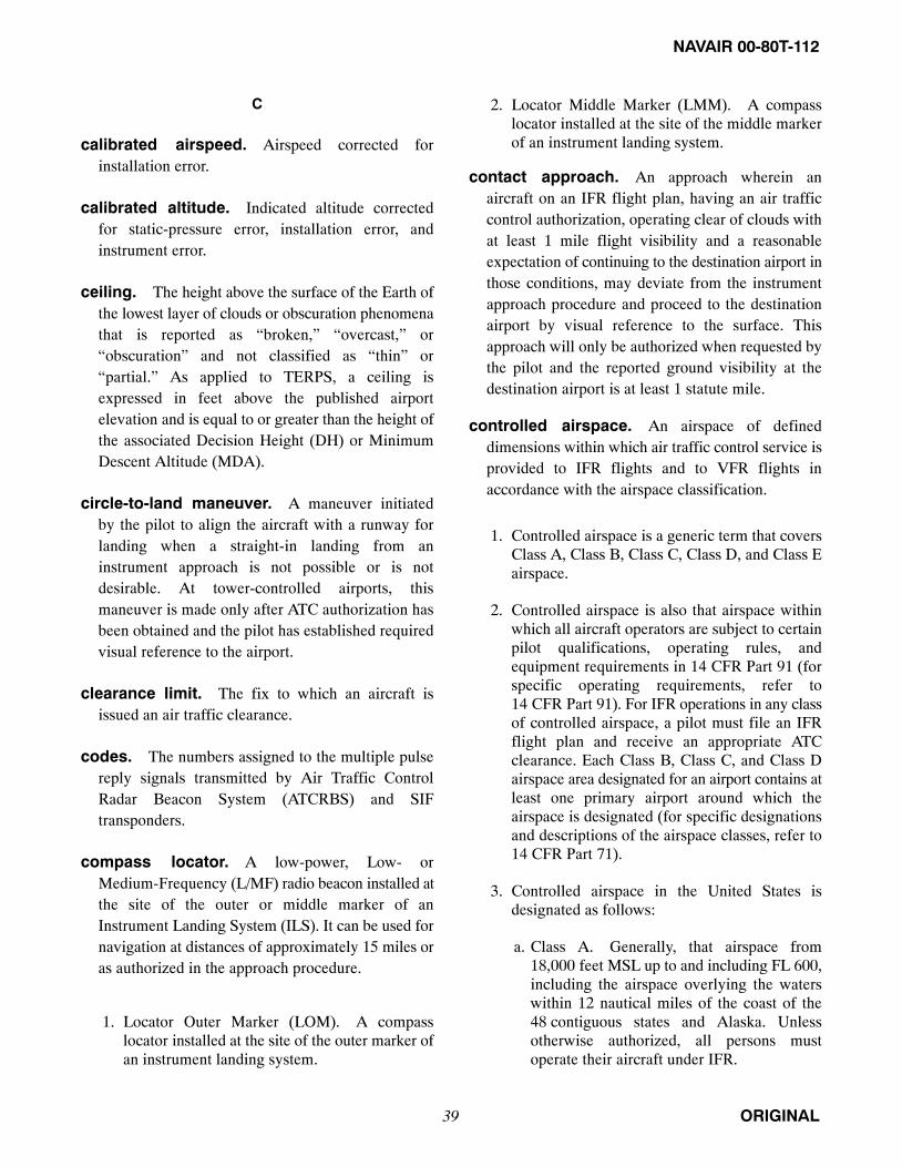
NAVAIR 00-80T-112
ORIGINAL39
C
calibrated airspeed. Airspeed corrected forinstallation error.
calibrated altitude. Indicated altitude correctedfor static-pressure error, installation error, andinstrument error.
ceiling. The height above the surface of the Earth ofthe lowest layer of clouds or obscuration phenomenathat is reported as “broken,” “overcast,” or“obscuration” and not classified as “thin” or“partial.” As applied to TERPS, a ceiling isexpressed in feet above the published airportelevation and is equal to or greater than the height ofthe associated Decision Height (DH) or MinimumDescent Altitude (MDA).
circle-to-land maneuver. A maneuver initiatedby the pilot to align the aircraft with a runway forlanding when a straight-in landing from aninstrument approach is not possible or is notdesirable. At tower-controlled airports, thismaneuver is made only after ATC authorization hasbeen obtained and the pilot has established requiredvisual reference to the airport.
clearance limit. The fix to which an aircraft isissued an air traffic clearance.
codes. The numbers assigned to the multiple pulsereply signals transmitted by Air Traffic ControlRadar Beacon System (ATCRBS) and SIFtransponders.
compass locator. A low-power, Low- orMedium-Frequency (L/MF) radio beacon installed atthe site of the outer or middle marker of anInstrument Landing System (ILS). It can be used fornavigation at distances of approximately 15 miles oras authorized in the approach procedure.
1. Locator Outer Marker (LOM). A compasslocator installed at the site of the outer marker ofan instrument landing system.
2. Locator Middle Marker (LMM). A compasslocator installed at the site of the middle markerof an instrument landing system.
contact approach. An approach wherein anaircraft on an IFR flight plan, having an air trafficcontrol authorization, operating clear of clouds withat least 1 mile flight visibility and a reasonableexpectation of continuing to the destination airport inthose conditions, may deviate from the instrumentapproach procedure and proceed to the destinationairport by visual reference to the surface. Thisapproach will only be authorized when requested bythe pilot and the reported ground visibility at thedestination airport is at least 1 statute mile.
controlled airspace. An airspace of defineddimensions within which air traffic control service isprovided to IFR flights and to VFR flights inaccordance with the airspace classification.
1. Controlled airspace is a generic term that coversClass A, Class B, Class C, Class D, and Class Eairspace.
2. Controlled airspace is also that airspace withinwhich all aircraft operators are subject to certainpilot qualifications, operating rules, andequipment requirements in 14 CFR Part 91 (forspecific operating requirements, refer to14 CFR Part 91). For IFR operations in any classof controlled airspace, a pilot must file an IFRflight plan and receive an appropriate ATCclearance. Each Class B, Class C, and Class Dairspace area designated for an airport contains atleast one primary airport around which theairspace is designated (for specific designationsand descriptions of the airspace classes, refer to14 CFR Part 71).
3. Controlled airspace in the United States isdesignated as follows:
a. Class A. Generally, that airspace from18,000 feet MSL up to and including FL 600,including the airspace overlying the waterswithin 12 nautical miles of the coast of the48 contiguous states and Alaska. Unlessotherwise authorized, all persons mustoperate their aircraft under IFR.

NAVAIR 00-80T-112
ORIGINAL 40
b. Class B. Generally, that airspace from thesurface to 10,000 feet MSL surrounding thebusiest airports of the nation in terms ofairport operations or passenger enplanements.The configuration of each Class B airspacearea is individually tailored and consists of asurface area and two or more layers (someClass B airspace areas resemble upside-downwedding cakes) and is designed to contain allpublished instrument procedures once anaircraft enters the airspace. An ATC clearanceis required for all aircraft to operate in thearea, and all aircraft that are so cleared receiveseparation services within the airspace. Thecloud clearance requirement for VFRoperations is “clear of clouds.”
c. Class C. Generally, that airspace from thesurface to 4,000 feet above the airportelevation (charted in MSL) surrounding thoseairports that have an operational controltower, are serviced by a radar approachcontrol, and have a certain number of IFRoperations or passenger enplanements.Although the configuration of each Class Carea is individually tailored, the airspaceusually consists of a surface area with a 5nautical-mile (nm) radius, an outer circle witha 10 nm radius that extends from 1,200 feet to4,000 feet above the airport elevation, and anouter area. Each person must establishtwo-way radio communications with the ATCfacility providing air traffic services prior toentering the airspace and thereafter maintainthose communications while within theairspace. VFR aircraft are only separated fromIFR aircraft within the airspace.
d. Class D. Generally, that airspace from thesurface to 2,500 feet above the airportelevation (charted in MSL) surrounding thoseairports that have an operational controltower. The configuration of each Class Dairspace area is individually tailored and wheninstrument procedures are published, theairspace will normally be designed to containthe procedures. Arrival extensions forinstrument approach procedures may be ClassD or Class E airspace. Unless otherwiseauthorized, each person must establishtwo-way radio communications with the ATCfacility providing air traffic services prior to
entering the airspace and thereafter maintainthose communications while in the airspace.No separation services are provided to VFRaircraft.
e. Class E. Generally, if the airspace is notClass A, Class B, Class C, or Class D, and itis controlled airspace, it is Class E airspace.Class E airspace extends upward from eitherthe surface or a designated altitude to theoverlying or adjacent controlled airspace.When designated as a surface area, theairspace will be configured to contain allinstrument procedures. Also in this class areFederal airways, airspace beginning at either700 or 1,200 feet AGL used to transitionto/from the terminal or en route environment,en route domestic, and offshore airspace areasdesignated below 18,000 feet MSL. Unlessdesignated at a lower altitude, Class Eairspace begins at 14,500 MSL over theUnited States, including that airspaceoverlying the waters within 12 nautical milesof the coast of the 48 contiguous states andAlaska, up to, but not including, 18,000 feetMSL, and the airspace above FL 600.
cruise. A word used in an ATC clearance toauthorize a pilot to conduct flight at any altitude fromthe Minimum En Route Altitude/MinimumObstruction Clearance Altitude (MEA/MOCA) up toand including the altitude specified in the clearance.The pilot may level off at any intermediary altitudewithin this block of airspace. Climb/descent withinthe block is to be made at the discretion of the pilot;however, once the pilot starts descent and reportsleaving an altitude in the block, he/she may not returnto that altitude without additional ATC clearance.Further, it is approval for the pilot to proceed to andmake an approach at destination airport, and can beused in conjunction with:
1. An airport clearance limit at locations with anapproved/prescribed instrument approachprocedure. The FARs require that if aninstrument letdown to an airport is necessary, thepilot shall make the letdown in accordance withan approved/prescribed instrument approachprocedure for that airport, or
2. An airport clearance limit at locations that arewithin/below/outside controlled airspace and

NAVAIR 00-80T-112
ORIGINAL41
without an approved/prescribed instrumentapproach procedure. Such a clearance is notauthorization for the pilot to descend under IFRconditions below applicable MEA/MOCA nordoes it imply ATC is exercising control overaircraft in uncontrolled airspace; however, itprovides a means for the aircraft to proceed todestination airport and descend and land inaccordance with applicable FARs governingVFR flight operations. Also, this provides searchand rescue protection until such time as the IFRflight plan is closed.
D
decision height. The height, specified in MSL,above the highest runway elevation in the touchdownzone at which a missed approach shall be initiated ifthe required visual reference has not beenestablished. This term is used only in procedureswhere an electronic glideslope provides thereference for descent, as in ILS or PrecisionApproach Radar (PAR).
defense visual flight rules. Special visual flightrules applicable to those flights that operate within orpenetrate an ADIZ.
density altitude. Pressure altitude corrected forexisting free air temperature.
departure control. Air traffic control serviceprovided to pilots departing an airport.
distance measuring equipment. Electronicnavigation equipment for finding the slant rangedistance in nautical miles between an aircraft and aground station by measuring time interval betweenpulses from an airborne radar and the reception ofanswering pulses from a transponder at the groundstation.
DoD FLIP. Department of Defense FlightInformation Publications used for flight planning, enroute, and terminal operations. FLIP is produced bythe National Geospatial-Intelligence Agency (NGA)for worldwide use. United States Government FlightInformation Publications (en route charts andinstrument approach procedure charts) are
incorporated in DoD FLIP for use in the NationalAirspace System (NAS).
domestic airspace. Airspace that overlies thecontinental land mass of the United States plusHawaii and U.S. possessions. Domestic airspaceextends to 12 miles offshore.
downburst. A strong downdraft that induces anoutburst of damaging winds on or near the ground.Damaging winds, either straight or curved, are highlydivergent. The sizes of downbursts vary from ½ mileor less to more than 10 miles. An intense downburstoften causes widespread damage. Damaging winds,lasting 5 to 30 minutes, could reach speeds as high as120 knots.
due regard. A phase of flight wherein an aircraftcommander of a state-operated aircraft assumesresponsibility to separate his/her aircraft from allother aircraft.
E
emergency safe altitude. An altitude expressedin 100-foot increments providing 1,000 feet ofclearance (2,000 feet in designated mountainousareas) over all obstructions/terrain within 100 milesof the navigational aid on which the instrumentapproach (AL/JAL) chart is centered.
equivalent airspeed. Calibrated airspeedcorrected for compressibility error.
expected further clearance time. The time atwhich it is expected that additional clearance will beissued to an aircraft.
expedite. Used by ATC when prompt compliance isrequired to avoid the development of an imminentsituation. Expedite climb/descent normally indicatesto a pilot that the approximate best rate ofclimb/descent should be used without requiring anexceptional change in aircraft handlingcharacteristics.
F
federal airway. Airspace of defined dimensions inwhich certain additional rules apply (described in

NAVAIR 00-80T-112
ORIGINAL 42
FAR Part 71) and depicted as a colored or VORairway that extends upward from 700 or 1,200 feetAGL to, but not including, 18,000 feet MSL exceptthat Federal airways for Hawaii have no upper limit.
final approach — IFR. The flightpath of an aircraftthat is inbound to the airport on an approved finalinstrument approach course, beginning at the point ofinterception of that course and extending to theairport or the point where circling for landing ormissed approach is executed.
flight level. A level of constant atmosphericpressure that is related to the standard pressure datumof 29.92 inches of mercury.
flight plan. Specified information provided to airtraffic service units, relative to the intended flight ofan aircraft.
flight service station. Air traffic facilities thatprovide pilot briefing, en route communications andVFR search and rescue services, assist lost aircraftand aircraft in emergency situations, relay ATCclearances, originate Notices to Airmen, broadcastaviation weather and NAS information, receive andprocess IFR flight plans, and monitor NAVAIDs. Inaddition, at selected locations, FSSs provide En routeFlight Advisory Service (Flight Watch), take weatherobservations, issue airport advisories, and adviseCustoms and Immigration of transborder flights.
flight watch. A shortened term for use in air-groundcontacts to identify the flight service stationproviding En route Flight Advisory Service (e.g.,“Oakland Flight Watch).”
G
glideslope intercept altitude. The minimumaltitude to intercept the glideslope/path on aprecision approach. The intersection of the publishedintercept altitude with the glideslope/path,designated on government charts by the lightningbolt symbol, is the precision Final Approach Fix(FAF); however, when the approach chart shows analternative lower glideslope intercept altitude, and
ATC directs a lower altitude, the resultant lowerintercept position is then the FAF.
global positioning system. A space-based radiopositioning, navigation, and time-transfer system.The system provides highly accurate position andvelocity information, and precise time, on acontinuous global basis, to an unlimited number ofproperly equipped users. The system is unaffected byweather and provides a worldwide common gridreference system. The GPS concept is predicatedupon accurate and continuous knowledge of thespatial position of each satellite in the system withrespect to time and distance from a transmittingsatellite to the user. The GPS receiver automaticallyselects appropriate signals from the satellites in viewand translates these into three-dimensional position,velocity, and time. System accuracy for civil users isnormally 100 meters horizontally.
go around. Instructions for a pilot to abandonhis/her approach to landing. Additional instructionsmay follow. Unless otherwise advised by ATC, aVFR aircraft or an aircraft conducting visualapproach should overfly the runway while climbingto traffic pattern altitude and enter the traffic patternvia the crosswind leg. A pilot on an IFR flight planmaking an instrument approach should execute thepublished missed approach procedure or proceed asinstructed by ATC; for example, “GO AROUND”(additional instructions if required).
ground controlled approach. A radar approachsystem operated from the ground by air trafficcontrol personnel transmitting instructions to thepilot by radio.
groundspeed. True airspeed corrected for windeffects.
H
heading. The direction in which the longitudinalaxis of an aircraft is pointed, usually expressed indegrees from North (true, magnetic, or compass).
height above airport. Indicates the height of theMDA above the published airport elevation. Height

NAVAIR 00-80T-112
ORIGINAL43
Above Airport (HAA) will be published inconjunction with all circling minimums.
height above touchdown. Indicates the height ofthe DH or MDA above the highest runway elevationin the touchdown zone. Height Above Touchdown(HAT) will be published in conjunction with allstraight-in minimums.
helipad (touchdown area). That part of thelanding and takeoff area where it is preferred that thehelicopter alight.
heliport. An area, either at ground level or elevatedon a structure, that is used or intended to be used forthe landing and takeoff of helicopters and includessome or all of the various facilities useful tohelicopter operation such as helicopter parking,waiting room, fueling, and maintenance equipment.
helistop. A heliport, either at ground level orelevated on a structure, for the landing and takeoff ofhelicopters, but without auxiliary facilities such aswaiting room, hangar parking, maintenance, orfueling equipment.
holding fix. A specified fix used as a reference pointin establishment of and maintaining the position ofan aircraft while holding.
holding procedure. A predetermined maneuverthat keeps an aircraft within a specified airspacewhile awaiting further clearance.
I
IFR aircraft. An aircraft conducting flights inaccordance with the instrument flight rules.
IFR flight. Flight conducted in accordance with theinstrument flight rules.
immediately. Used by ATC or pilots when suchaction compliance is required to avoid an imminentsituation.
indicated airspeed. The airspeed displayed by theairspeed indicator.
indicated altitude. Altitude as shown by a pressureor barometric altimeter uncorrected for instrumenterror and uncompensated for variations fromstandard atmospheric conditions.
indicated Mach number. Mach number displayedon the Mach indicator.
initial approach. That part of an instrumentapproach procedure consisting of the first approachto the first navigational facility associated with theprocedure or to a predetermined fix.
instrument approach procedure. A series ofpredetermined maneuvers for the orderly transfer ofan aircraft under instrument flight conditions fromthe beginning of the initial approach to a landing or toa point from which a landing may be made visually. Itis prescribed and approved for a specific airport bycompetent authority.
instrument landing system. A precisioninstrument approach system that normally consistsof the following electronic components and visualaids:
1. Localizer.
2. Glideslope.
3. Outer marker.
4. Middle marker.
5. Approach lights.
instrument meteorological conditions.Meteorological conditions expressed in terms ofvisibility, distance from clouds, and ceiling less thanthe minimums specified for visual meteorologicalconditions. Instrument Meteorological Conditions(IMC) exist anytime a visible horizon is notdistinguishable.
international civil aviation organization. Aspecialized agency of the United Nations whoseobjective is to develop the principles and techniquesof international air navigation and to foster planningand development of international civil air transport.

NAVAIR 00-80T-112
ORIGINAL 44
There are seven ICAO regions that are described inthe DoD FLIP General Planning and Area Planningpublications.
international flight information manual. Apublication designed primarily as a pilot’s preflightplanning guide for flights into foreign airspace andfor flights returning to the U.S. from foreignlocations.
interrogator. The ground-based surveillance radarbeacon transmitter/receiver that scans insynchronism with a primary radar, transmittingdiscrete radio signals that repetitiously request alltransponders on the mode being used to reply. Thereplies received are then mixed with the primaryradar video to be displayed on the plan positionindicators.
J
jet routes. A high-altitude route system at18,000 feet MSL to flight level 450, inclusive. Jetroutes are predicated on high-altitude navigationalaids.
joint military/civil airport. An airport owned bythe military or a community, or both, where anagreement exists for joint civil/military, fixed-basedaviation operations.
joint use restricted area. An area wherein anaircraft may operate if prior permission has beengranted by either the restricted area “using agency”or the “controlling agency.” (1) The using agencyorganization, or military command whose activitywithin a restricted area necessitated the area being sodesignated; except that, in the case of those restrictedarea/military climb corridors that do not have adesignated controlling agency, the using agency is amilitary air traffic control facility that may becontacted for transit through the climb corridor. Theusing agency notifies the controlling agencywhenever permission may be granted by thecontrolling agency for transit of, or flight within, arestricted area. (2) The controlling agency is a
designated ATC facility that may authorize transit ofa restricted area.
K
knot. One nautical mile (6,076.1033 feet) per hour.
L
land and hold short operations. Operations thatinclude simultaneous takeoffs and landings and/orsimultaneous landings when a landing aircraft is ableand is instructed by the controller to hold short of theintersecting runway/taxiway or designatedhold-short point. Pilots are expected to inform thecontroller promptly if the hold-short clearancecannot be accepted.
landing minimums. The minimum visibilityprescribed for landing a civil aircraft while using aninstrument approach procedure. The minimumapplies with other limitations set forth in 14 CFRPart 91 with respect to the Minimum DescentAltitude (MDA) or Decision Height (DH) prescribedin the instrument approach procedures as follows:
1. Straight-in landing minimums. A statement ofMDA and visibility, or DH and visibility,required for a straight-in landing on a specifiedrunway, or
2. Circling minimums. A statement of MDA andvisibility required for the circle-to-landmaneuver.
Note
Descent below the established MDA or DHis not authorized during an approach unlessthe aircraft is in a position from which anormal approach to the runway of intendedlanding can be made and adequate visualreference to required visual cues ismaintained.
localizer. The component of an ILS that providescourse guidance to the runway.
localizer-type directional aid. A facility ofcomparable utility and accuracy to a localizer butwhich is not part of a complete ILS and will not bealigned with the runway. Localizer-type DirectionalAid (LDA) is more accurate than SDF.

NAVAIR 00-80T-112
ORIGINAL45
lost communications. Loss of the ability tocommunicate by radio. Aircraft are sometimesreferred to as NORDO (No Radio). Standard pilotprocedures are specified in 14 CFR Part 91. Radarcontrollers issue procedures for pilots to follow in theevent of lost communications during a radarapproach when weather reports indicate an aircraftwill likely encounter IFR weather conditions duringthe approach.
M
Mach number. A number expressing the ratio of thespeed of a body or of a point on a body with respect tothe surrounding air or other fluid, or speed of a flow,to the speed of sound in the medium. Thus, a MachNumber of 1.0 indicates a speed equal to the speed ofsound.
maintain. The altitude/flight level instructions in anATC clearance normally require that a pilot“maintain” the altitude/flight level at which the flightwill operate when in controlled airspace.Altitude/flight level changes while en route shouldbe requested prior to the time the change is desired.
mandatory altitude (instrumentapproach). The MSL altitude vertical to agraphic location that an aircraft must maintain duringa portion of an instrument approach. Therequirement for such may be created by airspaceseparation criteria or airspace separation criteria inconjunction with obstruction clearance criteria. Amandatory altitude will be depicted as an underlinednumber with a line above it.
maximum authorized altitude. A MaximumAuthorized Altitude (MAA) is the highest altitude atwhich adequate reception of navigational aid signalsis assured. The establishment of an MAA at 40,000feet MSL means that adequate reception on a jet routeso designated is assured up to, and including, 40,000feet MSL.
military assumes responsibility for separationof aircraft. Military Assumes Responsibility forSeparation of Aircraft (MARSA) shall be authorized
only for those special military operations that arespecified in a letter of agreement or other appropriateFAA or military documents.
minimum altitude (instrumentapproach). MSL altitude vertical to a geographiclocation below which an aircraft may not descendduring an instrument approach until after passing thelocation. The requirement for a minimum altitudemay be created by obstruction clearance criteria orairspace separation criteria. On the approach plates, aminimum altitude will be depicted as an underlinednumber.
minimum crossing altitude. The lowest altitudeat certain radio fixes at which an aircraft must crosswhen proceeding in the direction of a higherminimum en route IFR altitude.
minimum descent altitude. An altitude, specifiedin feet above MSL, below which descent will not bemade until visual reference has been established withthe runway environment and the aircraft is in aposition to execute a normal landing. Minimumdescent altitudes apply to nonprecision, straight-in,and circling approaches.
minimum en route altitude. The altitudeestablished between navigational aids or reportingpoints on airways, air routes, or advisory routes, thatwill meet obstruction clearance requirements andwill also ensure acceptable navigational signalcoverage unless otherwise indicated.
minimum fuel. Indicates that an aircraft’s fuelsupply has reached a state where, upon reaching thedestination, it can accept little or no delay. This is notan emergency situation but merely indicates anemergency situation is possible should any unduedelay occur.
minimum IFR altitudes. Minimum altitudes forIFR operations as prescribed in 14 CFR Part 91.These altitudes are published on aeronautical chartsand prescribed in 14 CFR Part 95 for airways androutes and in 14 CFR Part 97 for standard instrumentapproach procedures. If no applicable minimumaltitude is prescribed in 14 CFR Part 95 or

NAVAIR 00-80T-112
ORIGINAL 46
14 CFR Part 97, the following minimum IFRaltitude applies:
1. In designated mountainous areas, 2,000 feetabove the highest obstacle within a horizontaldistance of 4 nautical miles from the course to beflown; or
2. Other than mountainous areas, 1,000 feet abovethe highest obstacle within a horizontal distanceof 4 nautical miles from the course to be flown;or as otherwise authorized by the Administratoror assigned by ATC.
minimum obstruction clearance altitude. Thespecified altitude in effect between radio fixes onVOR/TACAN/LF airway, off-airway routes, or routesegments, that meets obstruction clearancerequirements for the entire route segment andensures acceptable navigational signal coverage onlywithin 22 nautical miles of a VOR.
minimum reception altitude. The lowest altituderequired to receive adequate signals to determinespecific VOR/VORTAC/TACAN fixes.
minimum safe altitude. Altitudes depicted onapproach charts that provide at least 1,000 feet ofobstacle clearance for emergency use within aspecified distance from the navigation facility uponwhich a procedure is predicated. These altitudes willbe identified as Minimum Sector Altitudes orEmergency Safe Altitudes and are established asfollows:
1. Minimum sector altitudes. Altitudes depictedon approach charts that provide at least1,000 feet of obstacle clearance within a 25-mileradius of the navigation facility upon which theprocedure is predicated. Sectors depicted onapproach charts must be at least 90 degrees inscope. These altitudes are for emergency useonly and do not necessarily ensure acceptablenavigational signal coverage.
2. Emergency safe altitudes. Altitudes depictedon approach charts that provide at least1,000 feet of obstacle clearance innonmountainous areas and 2,000 feet of obstacleclearance in designated mountainous areas
within a 100-mile radius of the navigationfacility upon which the procedure is predicatedand normally used only in military procedures.These altitudes are identified in publishedprocedures as “Emergency Safe Altitudes.”
minimum vectoring altitude. The lowestaltitude, expressed in feet above mean sea level, thataircraft will be vectored by a radar controller. Thisaltitude ensures communications and radar coverageand meets obstruction clearance criteria.
missed approach.
1. A maneuver conducted by a pilot when aninstrument approach cannot be completed to alanding. The route of flight and altitude areshown on instrument approach procedure charts.A pilot executing a missed approach prior to theMissed Approach Point (MAP) must continuealong the final approach to the MAP. The pilotmay climb immediately to the altitude specifiedin the missed approach procedure.
2. A term used by the pilot to inform ATC thathe/she is executing the missed approach.
At locations where ATC radar service is provided, thepilot should conform to radar vectors when provided byATC in lieu of the published missed approachprocedure.
missed approach point. A point prescribed ineach instrument approach procedure at which amissed approach procedure shall be executed if therequired visual reference does not exist and/or a safelanding cannot be made.
mode. The number or letter referring to the specificpulse spacing of the signal transmitted by aninterrogator. (See radar beacon.)
N
NAVAID classes. VOR, VORTAC, and TACANaids are classed according to their operational use.The three classes of NAVAIDs are:
1. T. Terminal.
2. L. Low altitude.
3. H. High altitude.

NAVAIR 00-80T-112
ORIGINAL47
nautical mile. A unit of distance equal to 1 minuteof a great circle (6,076.1033 feet).
nonjoint use of restricted area. For restrictedareas that are not joint use, or for areas not controlledby Air Traffic Service (ATS), the pilot filing an IFRor VFR-on-top flight plan must obtain clearancefrom the using activity. Failure to advise ATS thatclearance has been obtained will result in ATSrouting to avoid the area. An exception applies toaircraft flying in accordance with an approvedAltitude Reservation (ALTRV). When flying VFR,the pilot is responsible for obtaining approval fromthe using or controlling agency prior to penetration ortransit of a restricted area.
nonprecision approach procedure. A standardinstrument approach procedure in which noelectronic glideslope is provided.
nonradar. Precedes other terms and generallymeans without the use of radar, such as:
1. Nonradar approach. Used to describeinstrument approaches for which courseguidance on final approach is not provided byground-based precision or surveillance radar.Radar vectors to the final approach course may ormay not be provided by ATC. Examples ofnonradar approaches are VOR, NDB, TACAN,and ILS/MLS approaches.
2. Nonradar approach control. An ATC facilityproviding approach control service without theuse of radar.
3. Nonradar arrival. An aircraft arriving at anairport without radar service or at an airportserved by a radar facility and radar contact hasnot been established or has been terminated dueto a lack of radar service to the airport.
4. Nonradar route. A flight path or route overwhich the pilot is performing his/her ownnavigation. The pilot may be receiving radarseparation, radar monitoring, or other ATCservices while on a nonradar route.
5. Nonradar separation. The spacing of aircraft inaccordance with established minimums without
the use of radar (e.g., vertical, lateral, orlongitudinal separation).
notice to airmen. A notice containing information(not known sufficiently in advance to publicize byother means) concerning the establishment,condition, or change in any component (facility,service, or procedure of, or hazard in, the NationalAirspace System) the timely knowledge of which isessential to personnel concerned with flightoperations.
1. NOTAM(D). A NOTAM given (in addition tolocal dissemination) distant disseminationbeyond the area of responsibility of the flightservice station. These NOTAMs will be storedand available until canceled.
2. NOTAM(L). A NOTAM given localdissemination by voice and other means, such astelautograph and telephone, to satisfy local userrequirements.
3. FDC NOTAM. A NOTAM regulatory innature, transmitted by a U.S. NOTAM Facility(USNOF) and given system-wide dissemination.
O
option approach. An approach requested andconducted by a pilot that will result in atouch-and-go, missed approach, low approach,stop-and-go, or full stop landing.
overhead maneuver. A series of predeterminedmaneuvers prescribed for aircraft (often information) for entry into the Visual Flight Rules(VFR) traffic pattern and to proceed to a landing. Anoverhead maneuver is not an Instrument Flight Rules(IFR) approach procedure. An aircraft executing anoverhead maneuver is considered VFR and the IFRflight plan is canceled when the aircraft reaches theinitial point on the initial approach portion of themaneuver. The pattern usually specifies thefollowing:
1. The radio contact required of the pilot.
2. The speed to be maintained.
3. An initial approach 3 to 5 miles in length.

NAVAIR 00-80T-112
ORIGINAL 48
4. An elliptical pattern consisting of two180-degree turns.
5. A break point at which the first 180-degree turnis started.
6. The direction of turns.
7. Altitude (at least 500 feet above the conventionalpattern).
8. A rollout on final approach not less than ¼ milefrom the landing threshold and not less than 300feet above the ground.
P
penetration. That portion of a published highaltitude terminal instrument approach procedure thatprescribes a descent path, from the fix on which theprocedure is based, to a fix or altitude from which anapproach to the airport is made.
pilot-to-dispatcher. A communication facilityestablished to enable pilots to transmit non-ATCinformation (e.g., servicing, maintenance, VIPinformation, etc.) to base operations.
pilot’s discretion. When used in conjunction withaltitude assignments, means that ATC has offered thepilot the option of starting climb or descent wheneverhe/she wishes and conducting the climb or descent atany rate he/she wishes. He/she may temporarily leveloff at any intermediate altitude; however, oncehe/she has vacated an altitude, he/she may not returnto that altitude.
precision approach radar. Radar equipment insome ATC facilities operated by the FAA and/or themilitary services at joint-use civil/military locationsand separate military installations to detect anddisplay azimuth, elevation, and range of aircraft onthe final approach course to a runway. Thisequipment may be used to monitor certain nonradarapproaches, but is primarily used to conduct aprecision instrument approach (PAR) wherein thecontroller issues guidance instructions to the pilotbased on the position of the aircraft in relation to thefinal approach course (azimuth), the glidepath
(elevation), and the distance (range) from thetouchdown point on the runway as displayed on theradarscope.
Note
The abbreviation PAR is also used to denotepreferential arrival routes in Air RouteTraffic Control (ARTCC) computers.
pressure altitude. The altitude above the standarddatum plane. This standard datum plane is where theair pressure is 29.92 inches of mercury (corrected to+15 °C).
procedure turn inbound. That point of aprocedure turn maneuver where course reversal hasbeen completed and an aircraft is establishedinbound an intermediate approach segment or finalapproach course. A report of PROCEDURE TURNINBOUND is normally used by ATC as a positionreport for separation purposes.
prohibited area. A specified area within the landareas of a state, or territorial waters adjacent thereto,through which the flight of aircraft is prohibited.
Q
QNE. The barometric pressure used for the standardaltimeter setting (29.92 inches Hg).
QNH. The barometric pressure as reported by aparticular station.
R
radar. A device that, by measuring the time intervalbetween transmission and reception of radio pulsesand correlating the angular orientation of the radiatedantenna beam or beams in azimuth and/or elevation,provides information on range, azimuth, and/orelevation of objects in the path of the transmittedpulses.
1. Primary radar. A radar system in which aminute portion of a radio pulse transmitted froma site is reflected by an object and then receivedback at that site for processing and display at anair traffic control facility.

NAVAIR 00-80T-112
ORIGINAL49
2. Secondary radar/radar beacon (ATCRBS). Aradar system in which the object to be detected isfitted with cooperative equipment in the form ofa radio receiver/transmitter (transponder). Radarpulses transmitted from the searchingtransmitter/receiver (interrogator) site arereceived in the cooperative equipment and usedto trigger a distinctive transmission from thetransponder. This reply transmission, rather thana reflected signal, is then received back at thetransmitter/receiver site for processing anddisplay at an air traffic control facility.
radar advisory. Term used to indicate that theprovision of advice and information is based on radarobservation.
radar contact. The term air traffic controllers use toindicate that an aircraft is identified on the radardisplay and that radar service can be provided untilradar identification is lost or radar service isterminated; when the aircraft is informed of RADARCONTACT, it automatically discontinues reportingover compulsory reporting points.
radar flight following. The general observation ofthe progress of identified aircraft targets to retaintheir identity sufficiently or the observation of themovement of specific radar targets.
radar handoff. That action whereby radaridentification of, radio communications with, and,unless otherwise specified, control responsibility foran aircraft is transferred from one controller toanother without interruption of radar flightfollowing.
radar identification. The process of ascertainingthat a radar target is the radar return from a particularaircraft.
radar service. A term that encompasses one ormore of the following services, based on the use ofradar, which can be provided by a controller to a pilotof a radar-identified aircraft:
1. Radar monitoring. The radar flight-followingof an aircraft, the primary navigation of which isbeing performed by its pilot, to observe and note
deviations from its authorized flightpath, airway,or route. As applied to the monitoring ofinstrument approaches from the final approachfix to the runway, it also includes the provision ofadvice on position relative to approach fixes andwhenever the aircraft proceeds outside theprescribed safety zones.
2. Radar navigation guidance. Vectoring aircraftto provide course guidance.
3. Radar separation. Radar spacing of aircraft inaccordance with established minimums.
4. Radar surveillance. The radar observation of agiven geographical area for the purpose ofperforming some radar function.
5. Radar vector. A heading issued to an aircraft toprovide navigational guidance by radar.
radial. A radial is a magnetic bearing extending froma VOR, VORTAC, or TACAN.
radio magnetic indicator. A radio-navigationinstrument coupled with a gyrosyn compass or thelike that indicates magnetic heading and bearing withrespect to a transmitting station.
reduced vertical separationminimums. Reduced Vertical SeparationMinimums (RVSM) reduce the vertical separationbetween Flight Level (FL) 290 to 410 from 2,000 feetto 1,000 feet and make six additional FLs availablefor operation. The additional FLs enable moreaircraft to fly more time/fuel efficient profiles andprovide the potential for enhanced airspace capacity.RVSM operators must receive authorization from theappropriate civil aviation authority. RVSM aircraftmust meet required equipage and altitude-keepingperformance standards. Operators must operate inaccordance with RVSM policies/proceduresapplicable to the airspace where they are flying.Additional information is found in the AIM/FAR.
reporting point. A specified geographic location inrelation to which the position of an aircraft can bereported.

NAVAIR 00-80T-112
ORIGINAL 50
rescue coordination center. A center establishedwithin an assigned search and rescue area to promoteefficient organization of search and rescue.
restricted area. A specified area within the landareas of a state, or territorial waters adjacent thereto,designated for other than air traffic control purposes,over which the flight of aircraft is restricted inaccordance with certain specified conditions.
runway condition reading. Numericaldecelerometer reading provided by air trafficcontrollers at USAF bases for use by the pilot indetermining runway braking action. The FlightInformation Handbook supplement provides asuggested table of equivalents for use by navalaviators in converting these readings to a comparablebraking action description.
S
safety alert. A safety alert issued by ATC to aircraftunder their control if ATC is aware the aircraft is at analtitude that, in the controller’s judgment, places theaircraft in unsafe proximity to terrain, obstructions,or other aircraft. The controller may discontinue theissuance of further alerts if the pilot advises he/she istaking action to correct the situation or has the otheraircraft in sight.
1. Terrain/obstruction alert. A safety alert issuedby ATC to aircraft under their control if ATC isaware the aircraft is at an altitude that, in thecontroller’s judgment, places the aircraft inunsafe proximity to terrain/obstructions (e.g.,LOW ALTITUDE ALERT, CHECK YOURALTITUDE IMMEDIATELY).
2. Aircraft conflict alert. A safety alert issued byATC to aircraft under their control if ATC isaware of an aircraft which is not under theircontrol at an altitude which, in the controller’sjudgment, places both aircraft in unsafeproximity to each other. With the alert, ATC willoffer the pilot an alternate course of action whenfeasible (e.g., TRAFFIC ALERT, ADVISEYOU TURN RIGHT HEADING ZERO NINER
ZERO OR CLIMB TO EIGHT THOUSANDIMMEDIATELY).
SIGMET advisory. These advisories are issued bythe National Weather Service and are identified aseither Nonconvective-WS or Convective-WST.These advisories are issued individually and theirinformation may be included in relevant portions ofAviation Area Forecasts (FAs). Normally, WSs andWSTs are issued separately and will automaticallyamend the relevant portion of the FA for the period ofthe advisory. The purpose of this service is to notifyen route pilots of the possibility of encounteringhazardous flying conditions that may not have beenprovided in preflight weather briefings. Refer toChapter 27 for SIGMET criteria.
simplified directional facility. A facility ofcomparable utility and accuracy to a localizer, butthat is not part of a complete ILS and will not bealigned with the runway. An approach facility similarto a localizer, except it may be offset up to 3 degreesfrom runway and the course may be wider. Lessaccurate than LDA.
single-frequency approach. A service providedunder a letter of agreement to military single-pilotedturbojet aircraft that permits use of a single UHFfrequency during approach for landing. Pilots willnot normally be required to change frequency fromthe beginning of the approach to touchdown exceptthat pilots conducting an en route descent arerequired to change frequency when control istransferred from the air route traffic control center tothe terminal facility. The abbreviation to SFA in theDoD FLIP IFR Supplement under“Communications” indicates this service is availableat an aerodrome.
single-piloted aircraft. Any aircraft that has onlyone set of flight controls or any aircraft that has twosets of flight controls and instruments and is beingoperated by only one pilot who meets therequirements of the NATOPS manual for that modelaircraft.
skid. A sidewise movement of an aircraft toward theoutside of the turn.

NAVAIR 00-80T-112
ORIGINAL51
slip. A sidewise movement of an aircraft toward theinside of the turn.
special use airspace. Airspace of defineddimensions identified by an area on the surface of theEarth wherein activities must be confined because oftheir nature and/or wherein limitations may beimposed upon aircraft operations that are not a part ofthose activities. Types of special use airspace are:
1. Alert area. Airspace that may contain a highvolume of pilot training activities or an unusualtype of aerial activity, neither of which ishazardous to aircraft. Alert areas are depicted onaeronautical charts for the information ofnonparticipating pilots. All activities within analert area are conducted in accordance withFederal aviation regulations, and pilots ofparticipating aircraft as well as pilots transitingthe area are equally responsible for collisionavoidance.
2. Controlled firing area. Airspace whereinactivities are conducted under conditions socontrolled as to eliminate hazards tononparticipating aircraft and to ensure the safetyof persons and property on the ground.
3. Military Operations Area (MOA). A MOA isairspace established outside of Class A airspacearea to separate or segregate certainnonhazardous military activities from IFR trafficand to identify for VFR traffic where theseactivities are conducted.
4. Prohibited area. Airspace designated under14 CFR Part 73 within which no person mayoperate an aircraft without the permission of theusing agency.
5. Restricted area. Airspace designated under14 CFR Part 73, within which the flight ofaircraft, though not wholly prohibited, is subjectto restriction. Most restricted areas aredesignated joint use and IFR/VFR operations inthe area may be authorized by the controllingATC facility when it is not being utilized by theusing agency. Restricted areas are depicted on enroute charts. Where joint use is authorized, thename of the ATC controlling facility is alsoshown.
6. Warning area. A warning area is airspace ofdefined dimensions extending from 3 nauticalmiles outward from the coast of the United Statesthat contains activity that may be hazardous tononparticipating aircraft. The purpose of suchwarning area is to warn nonparticipating pilots ofthe potential danger. A warning area may belocated over domestic or international waters orboth.
special VFR conditions (special VFR minimumweather conditions). Weather conditions thatare less than basic VFR weather conditions and thatpermit flight in a control zone clear of clouds with 1mile visibility.
special VFR operations. Aircraft operating inaccordance with clearances within control zones inweather conditions less than the basic VFR weatherminimums.
standard instrument departure. A preplanned,coded air traffic control IFR departure routing,preprinted for pilot use in graphic and textual ortextual form only.
standard rate turn. A turn in an aircraft in whichthe heading changes at the rate of 3° per second.
standard terminal arrival route. A preplanned,coded air traffic control IFR arrival routing,preprinted for pilot use in graphic and textual ortextual form only.
surveillance approach. An instrument approachconducted in accordance with directions issued by acontroller referring only to the surveillance radardisplay.
T
TACAN. An ultrahigh frequency tactical airnavigation system combining the functions of theomnidirectional radio range and distance measuringequipment to indicate the distance and bearing of anaircraft from a transmitting station.
TACAN-only aircraft. An aircraft possessingTACAN but no VOR navigational system capability.

NAVAIR 00-80T-112
ORIGINAL 52
terminal radar service area. Airspacesurrounding designated airports wherein ATCprovides radar vectoring, sequencing, and separationon a full-time basis for all IFR and participating VFRaircraft. The AIM contains an explanation ofTerminal Radar Service Area (TRSA). TRSAs aredepicted on VFR aeronautical charts. Pilotparticipation is urged but is not mandatory.
terminal VFR radar service. A national programinstituted to extend the terminal radar servicesprovided to Instrument Flight Rules (IFR) aircraft toVisual Flight Rules (VFR) aircraft. The program isdivided into four types service referred to as basicradar service, TRSA service, Class B service, andClass C service. The type of service provided at aparticular location is contained in theAirport/Facility Directory.
1. Basic radar service. These services areprovided for VFR aircraft by all commissionedterminal radar facilities. Basic radar serviceincludes safety alerts, traffic advisories, limitedradar vectoring when requested by the pilot, andsequencing at locations where procedures havebeen established for this purpose and/or whencovered by a letter of agreement. The purpose ofthis service is to adjust the flow of arriving IFRand VFR aircraft into the traffic pattern in a safeand orderly manner and to provide trafficadvisories to departing VFR aircraft.
2. TRSA service. This service provides, inaddition to basic radar service, sequencing of allIFR and participating VFR aircraft to the primaryairport and separation between all participatingVFR aircraft. The purpose of this service is toprovide separation between all participatingVFR aircraft and all IFR aircraft operating withinthe area defined as a TRSA.
3. Class C service. This service provides, inaddition to basic radar service, approvedseparation between IFR and VFR aircraft,sequencing of VFR aircraft, and sequencing ofVFR arrivals to the primary airport.
4. Class B service. This service provides, inaddition to basic radar service, approved
separation of aircraft based on IFR, VFR, and/orweight, and sequencing of VFR arrivals to theprimary airport(s).
track. The projection on the surface of the Earth ofthe path of an aircraft, the direction of which at anypoint is usually expressed in degrees from North(true or magnetic).
transition.
1. The general term that describes the change fromone phase of flight or flight condition to another(e.g., transition from en route flight to theapproach or transition from instrument flight tovisual flight).
2. A published procedure (DP Transition) used toconnect the basic DP to one of several en routeairways/jet routes, or a published procedure(STAR Transition) used to connect one of severalen route airways/jet routes to the basic STAR.(Refer to DP/STAR charts.)
transitional airspace. That portion of controlledairspace wherein aircraft change from one phase offlight or flight condition to another.
transponder. Airborne radar beacon receiver/transmitter that automatically receives radio signalsfrom all interrogators on the ground and selectivelyreplies with a specific reply pulse or pulse group onlyto those interrogations being received on the mode towhich it is set to respond.
tricolor visual approach slope indicator. Thetricolor approach slope indicator normally consistsof a single light unit projecting a three-color visualapproach path into the final approach area of therunway upon which the system is installed. In all ofthese systems, a below glidepath indication is red, oramber, and the on path indication green.
true airspeed. Equivalent airspeed corrected for airdensity error.
true altitude. Calibrated altitude corrected fornonstandard atmospheric conditions. Actual heightabove mean sea level.
true Mach number. Mach corrected for installationerror.
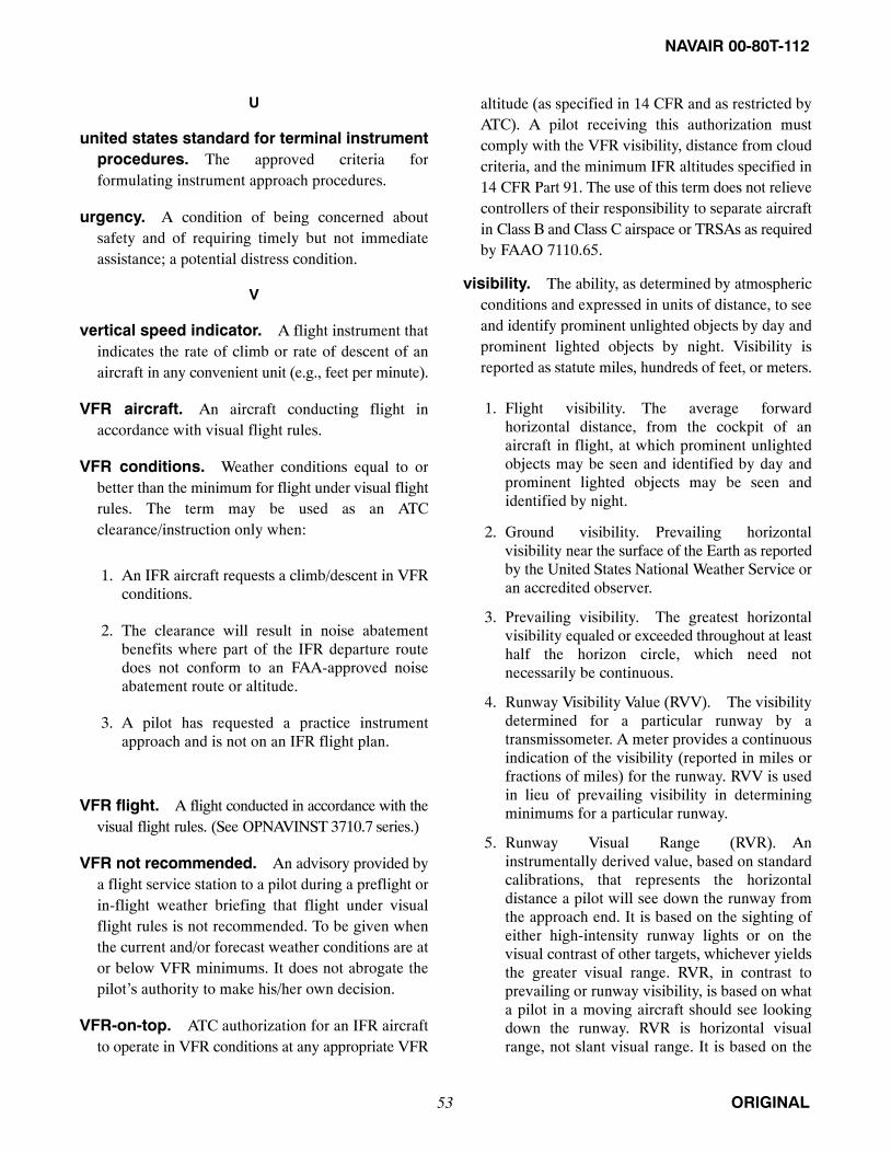
NAVAIR 00-80T-112
ORIGINAL53
U
united states standard for terminal instrumentprocedures. The approved criteria forformulating instrument approach procedures.
urgency. A condition of being concerned aboutsafety and of requiring timely but not immediateassistance; a potential distress condition.
V
vertical speed indicator. A flight instrument thatindicates the rate of climb or rate of descent of anaircraft in any convenient unit (e.g., feet per minute).
VFR aircraft. An aircraft conducting flight inaccordance with visual flight rules.
VFR conditions. Weather conditions equal to orbetter than the minimum for flight under visual flightrules. The term may be used as an ATCclearance/instruction only when:
1. An IFR aircraft requests a climb/descent in VFRconditions.
2. The clearance will result in noise abatementbenefits where part of the IFR departure routedoes not conform to an FAA-approved noiseabatement route or altitude.
3. A pilot has requested a practice instrumentapproach and is not on an IFR flight plan.
VFR flight. A flight conducted in accordance with thevisual flight rules. (See OPNAVINST 3710.7 series.)
VFR not recommended. An advisory provided bya flight service station to a pilot during a preflight orin-flight weather briefing that flight under visualflight rules is not recommended. To be given whenthe current and/or forecast weather conditions are ator below VFR minimums. It does not abrogate thepilot’s authority to make his/her own decision.
VFR-on-top. ATC authorization for an IFR aircraftto operate in VFR conditions at any appropriate VFR
altitude (as specified in 14 CFR and as restricted byATC). A pilot receiving this authorization mustcomply with the VFR visibility, distance from cloudcriteria, and the minimum IFR altitudes specified in14 CFR Part 91. The use of this term does not relievecontrollers of their responsibility to separate aircraftin Class B and Class C airspace or TRSAs as requiredby FAAO 7110.65.
visibility. The ability, as determined by atmosphericconditions and expressed in units of distance, to seeand identify prominent unlighted objects by day andprominent lighted objects by night. Visibility isreported as statute miles, hundreds of feet, or meters.
1. Flight visibility. The average forwardhorizontal distance, from the cockpit of anaircraft in flight, at which prominent unlightedobjects may be seen and identified by day andprominent lighted objects may be seen andidentified by night.
2. Ground visibility. Prevailing horizontalvisibility near the surface of the Earth as reportedby the United States National Weather Service oran accredited observer.
3. Prevailing visibility. The greatest horizontalvisibility equaled or exceeded throughout at leasthalf the horizon circle, which need notnecessarily be continuous.
4. Runway Visibility Value (RVV). The visibilitydetermined for a particular runway by atransmissometer. A meter provides a continuousindication of the visibility (reported in miles orfractions of miles) for the runway. RVV is usedin lieu of prevailing visibility in determiningminimums for a particular runway.
5. Runway Visual Range (RVR). Aninstrumentally derived value, based on standardcalibrations, that represents the horizontaldistance a pilot will see down the runway fromthe approach end. It is based on the sighting ofeither high-intensity runway lights or on thevisual contrast of other targets, whichever yieldsthe greater visual range. RVR, in contrast toprevailing or runway visibility, is based on whata pilot in a moving aircraft should see lookingdown the runway. RVR is horizontal visualrange, not slant visual range. It is based on the

NAVAIR 00-80T-112
ORIGINAL 54
measurement of a transmissometer made near thetouchdown point of the instrument runway and isreported in hundreds of feet. RVR is used in lieuof RVV and/or prevailing visibility indetermining minimums for a particular runway.
a. Touchdown RVR. The RVR visibilityreadout values obtained from RVR equipmentserving the runway touchdown zone.
b. Mid-RVR. The RVR readout valuesobtained from RVR equipment locatedmidfield of the runway.
c. Rollout RVR. The RVR readout valuesobtained from RVR equipment locatednearest the rollout end of the runway.
visual approach. An approach wherein an aircrafton an IFR flight plan, operating in VFR conditionsand having received an air traffic controlauthorization, may deviate from the prescribedinstrument approach procedures and proceed to theairport of destination by visual reference to thesurface.
visual approach slope indicator. A lightingsystem usable at night, or in limited visibility, thataids the pilot in maintaining a predeterminedglidepath on final approach. The lights are visible upto 15 miles at night and 5 miles by day. Each unit isequipped with a high-beam white light and alow-beam red filter that enables the pilot, when onthe proper glidepath, to see the front row of lights aswhite and the back row of lights as red on both sidesof the runway. If glidepath is too high, both rows oflights show white; if too low, they show red.
visual descent point. A defined point on the finalapproach course of a nonprecision straight-inapproach procedure from which normal descentfrom the MDA to the runway touchdown point maybe commenced, provided the approach threshold ofthat runway, or approach lights, or other markingsidentifiable with the approach end of that runway are
clearly visible to the aircrew. Aircrew should notdescend below the MDA prior to reaching the VDPand acquiring the necessary visual reference.
visual meteorological conditions. Basicweather conditions prescribed for flight under visualflight rules.
visual separation. A means of separating IFR,DVFR, and, where special programs are in effect,VFR aircraft in terminal areas wherein either of thefollowing methods is applied:
1. The tower controller sees the aircraft involvedand issues information and instructions, asnecessary, to ensure the aircraft avoid each other.
2. The pilot sees the other aircraft involved and,upon instructions from the controller, provideshis/her own separation by maneuvering his/heraircraft as necessary to avoid it. This may involvefollowing in-trail behind another aircraft orkeeping it in sight until it is no longer a factor. Apilot’s acceptance of traffic information andinstructions to follow another aircraft or providevisual separation from it is considered toconstitute acknowledgement that he/she sees theother aircraft and will avoid it.
W
wake turbulence. Phenomena resulting from thepassage of an aircraft through the atmosphere. Theterm includes vortices, thrust stream turbulence, jetblast, jet wash, propeller wash, and rotorwash bothon the ground and in the air.
waypoint. A predetermined geographical positionused for route/instrument approach definition,progress reports, published VFR routes, visualreporting points or points for transitioning and/orcircumnavigating controlled and/or special useairspace, that is defined relative to a VORTACstation or in terms of latitude/longitude coordinates.

NAVAIR 00-80T-112
ORIGINAL55
List of Abbreviations and AcronymsA
AAS. Airport Advisory Service.
ACLS. Automated Carrier Landing System.
ACM. Air Combat Maneuvering.
ADCUS. Advise Customs (message).
ADF. Automatic Direction Finder/Finding.
ADI. Attitude Direction Indicator.
ADIZ. Air Defense Identification Zone.
ADRL. Automatic Distribution Requirements List.
AFCS. Automatic Flight Control System.
AFM. Aircraft Flight Manual.
AGL. Above Ground Level.
AIM. Aeronautical Information Manual.
AIRMET. Airmen’s Meteorological Information.
AL. Low-Altitude Approach.
ALS. Approach Light System.
ALSF. Approach Light System with SequentialFlashing Lights.
ALTRV. Altitude Reservation.
AOA. Angle of Attack.
AP. Area Planning (FLIP).
ARTCC. Air Route Traffic Control Center.
ASDE. Airport Surface Detection Equipment.
ASE. Automatic Stabilization Equipment.
ASOS. Automated Surface Observing System (WXbroadcasts).
ASR. Airport Surveillance Radar.
ASW. Antisubmarine Warfare.
ATC. Air Traffic Control.
ATCRBS. Air Traffic Control Radar BeaconSystem.
ATCT. Airport Traffic Control Tower.
ATD. Along Track Distance.
ATIS. Automatic Terminal Information Service.
ATS. Air Traffic Service.
AWOS. Automated Weather Observing System(broadcasts).
AZ-EL. Azimuth/Elevation Scope Presentation.
B
BARO-VNAV. Barometric Vertical (altitude)Navigation.
BDHI. Bearing-Distance-Heading Indicator.
BRC. Base Recovery Course.
C
C/A. Coarse Acquisition (GPS).
CAS. Calibrated Airspeed.
CAT. Clear Air Turbulence.
CDI. Course Deviation Indicator.
CERAP. Center Radar Approach Control.
CF. Course to Fix. (GPS).
CFIT. Controlled Flight Into Terrain.
CFR. Code of Federal Regulations.
CONUS. Continental United States.
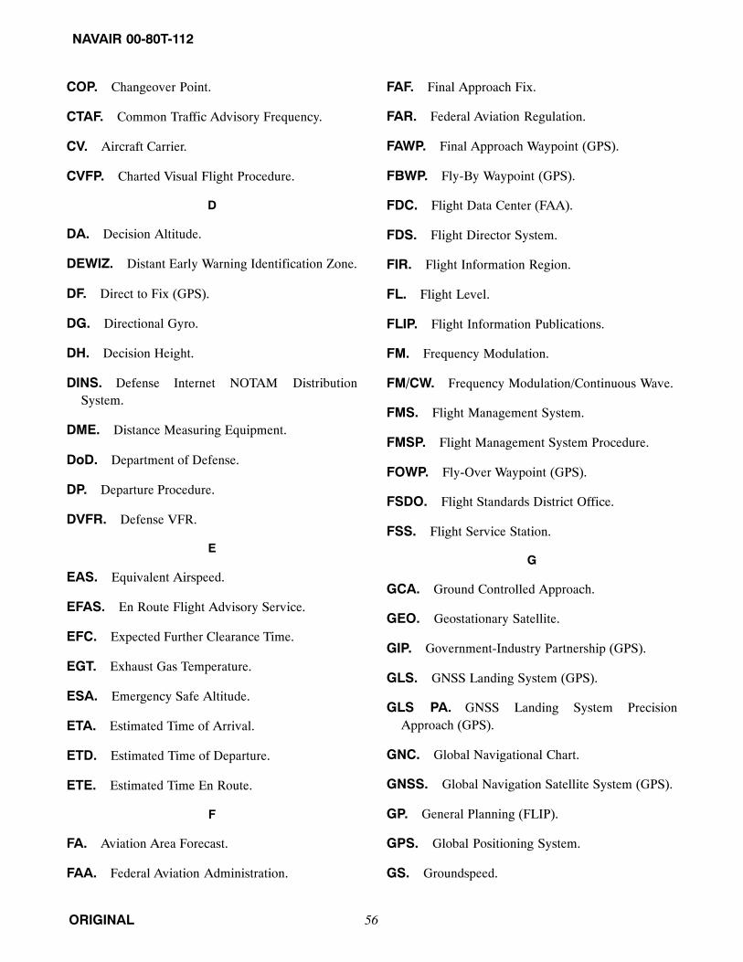
NAVAIR 00-80T-112
ORIGINAL 56
COP. Changeover Point.
CTAF. Common Traffic Advisory Frequency.
CV. Aircraft Carrier.
CVFP. Charted Visual Flight Procedure.
D
DA. Decision Altitude.
DEWIZ. Distant Early Warning Identification Zone.
DF. Direct to Fix (GPS).
DG. Directional Gyro.
DH. Decision Height.
DINS. Defense Internet NOTAM DistributionSystem.
DME. Distance Measuring Equipment.
DoD. Department of Defense.
DP. Departure Procedure.
DVFR. Defense VFR.
E
EAS. Equivalent Airspeed.
EFAS. En Route Flight Advisory Service.
EFC. Expected Further Clearance Time.
EGT. Exhaust Gas Temperature.
ESA. Emergency Safe Altitude.
ETA. Estimated Time of Arrival.
ETD. Estimated Time of Departure.
ETE. Estimated Time En Route.
F
FA. Aviation Area Forecast.
FAA. Federal Aviation Administration.
FAF. Final Approach Fix.
FAR. Federal Aviation Regulation.
FAWP. Final Approach Waypoint (GPS).
FBWP. Fly-By Waypoint (GPS).
FDC. Flight Data Center (FAA).
FDS. Flight Director System.
FIR. Flight Information Region.
FL. Flight Level.
FLIP. Flight Information Publications.
FM. Frequency Modulation.
FM/CW. Frequency Modulation/Continuous Wave.
FMS. Flight Management System.
FMSP. Flight Management System Procedure.
FOWP. Fly-Over Waypoint (GPS).
FSDO. Flight Standards District Office.
FSS. Flight Service Station.
G
GCA. Ground Controlled Approach.
GEO. Geostationary Satellite.
GIP. Government-Industry Partnership (GPS).
GLS. GNSS Landing System (GPS).
GLS PA. GNSS Landing System PrecisionApproach (GPS).
GNC. Global Navigational Chart.
GNSS. Global Navigation Satellite System (GPS).
GP. General Planning (FLIP).
GPS. Global Positioning System.
GS. Groundspeed.

NAVAIR 00-80T-112
ORIGINAL57
GSI. Glideslope Indicator.
GUS. Ground Uplink Station (GPS).
H
HAA. Height Above Airport.
HAT. Height Above Touchdown.
HDTA. High Density Traffic Airport.
HIRL. High Intensity Runway Lighting.
HIWAS. Hazardous In-Flight Weather AdvisoryService.
HSI. Horizontal Situation Indicator.
HUD. Heads-Up Display.
HWD. Horizontal Weather Depiction.
I
IAF. Initial Approach Fix.
IAP. Instrument Approach Procedure.
IAS. Indicated Airspeed.
IAWP. Initial Approach Waypoint (GPS).
ICAO. International Civil Aviation Organization.
IF. Intermediate Fix.
IFF. Identification Friend or Foe.
IFIM. International Flight Information Manual.
IFR. Instrument Flight Rules.
ILS. Instrument Landing System.
IM. Inner Marker.
IMC. Instrument Meteorological Conditions.
IMN. Indicated Mach Number.
IPA. Initial Penetration Altitude.
ITCZ. Intertropical Convergence Zone.
ITO. Instrument Takeoff.
J
JAL. High-Altitude Approach.
JNC. Jet Navigational Chart.
JOG. Joint Operations Graphic.
K
KIAS. Knots Indicated Airspeed.
L
L/MF. Low/Medium Frequency (NAVAIDs).
LAAS. Local Area Augmentation System (GPS).
LAHSO. Land And Hold Short Operations.
LDA. Localizer-type Directional Aid.
LF. Low Frequency.
LFM. Low-Power Fan Marker.
LIRL. Low Intensity Runway Lighting.
LMM. Locator Middle Marker.
LNAV. Lateral Navigation (GPS).
LOC. Localizer.
LOM. Locator Outer Marker.
LPV. Localizer Performance with Vertical Guidance.
M
MAA. Maximum Authorized Altitude.
MAHWP. Missed Approach Holding Waypoint(GPS).
MALSF. Medium Intensity Approach Light Systemwith Sequential Flashing Lights.
MALSR. Medium Intensity Approach Light Systemwith Runway Alignment Indicator Lights.
MAP. Missed Approach Point.

NAVAIR 00-80T-112
ORIGINAL 58
MARSA. Military Assumes Responsibility forSeparation of Aircraft.
MAWP. Missed Approach Waypoint (GPS).
MCA. Minimum Crossing Altitude.
MDA. Minimum Descent Altitude.
MDF. Manual Direction Finder.
MEA. Minimum En Route Altitude.
MEF. Maximum Elevation Figure.
MF. Medium Frequency.
MH. Magnetic Heading.
MHA. Minimum Holding Altitude.
MIA. Minimum IFR Altitude.
MIRL. Medium Intensity Runway Lighting.
MLS. Microwave Landing System.
MN. Mach Number.
MOA. Military Operations Area.
MOCA. Minimum Obstruction Clearance Altitude.
MRA. Minimum Reception Altitude.
MSA. Minimum Safe Altitude.
MSL. Mean Sea Level.
MTI. Moving Target Indicator.
MVA. Minimum Vectoring Altitude.
MWWA. Military Weather Warning Advisory.
N
NAS. National Airspace System/Naval Air Station.
NATOPS. Naval Aviation Training and OperatingProcedures Standardization.
NAVAID. Navigation Aid.
NAVICP. Navy Inventory Control Point.
NDB. Non-Directional Beacon.
NFDC. National Flight Data Center.
NFO. Naval Flight Officer.
NGA. National Geospatial-Intelligence Agency.
NM. Nautical Mile(s).
NORDO. No Radio.
NOTAM. Notice to Airmen.
NTSB. National Transportation Safety Board.
NTZ. No-Transgression Zone.
NWS. National Weather Service.
O
OAT. Outside Air Temperature.
ODALS. Omnidirectional Approach LightingSystem.
ONC. Operational Navigation Chart.
OPARS. Optimum Path Aircraft Routing System.
ORM. Operational Risk Management.
OROCA. Off-Route Obstruction ClearanceAltitude.
P
PAPI. Precision Approach Path Indicator.
PAR. Precision Approach Radar.
PFR. Primary Flight Reference.
PIREP. Pilot Report.
PMSV. Pilot-to-Metro Service.
PPS. Precise Position Service (GPS).
PRM. Precision Runway Monitor.
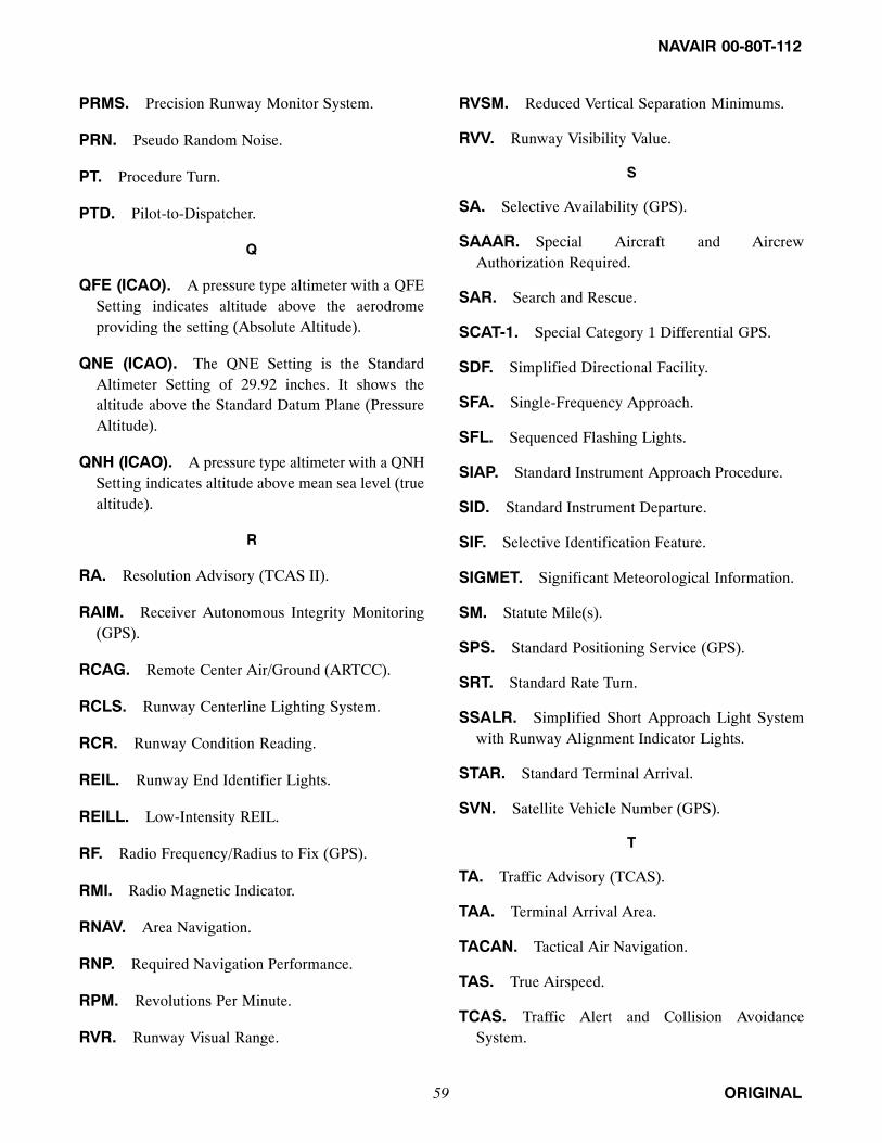
NAVAIR 00-80T-112
ORIGINAL59
PRMS. Precision Runway Monitor System.
PRN. Pseudo Random Noise.
PT. Procedure Turn.
PTD. Pilot-to-Dispatcher.
Q
QFE (ICAO). A pressure type altimeter with a QFESetting indicates altitude above the aerodromeproviding the setting (Absolute Altitude).
QNE (ICAO). The QNE Setting is the StandardAltimeter Setting of 29.92 inches. It shows thealtitude above the Standard Datum Plane (PressureAltitude).
QNH (ICAO). A pressure type altimeter with a QNHSetting indicates altitude above mean sea level (truealtitude).
R
RA. Resolution Advisory (TCAS II).
RAIM. Receiver Autonomous Integrity Monitoring(GPS).
RCAG. Remote Center Air/Ground (ARTCC).
RCLS. Runway Centerline Lighting System.
RCR. Runway Condition Reading.
REIL. Runway End Identifier Lights.
REILL. Low-Intensity REIL.
RF. Radio Frequency/Radius to Fix (GPS).
RMI. Radio Magnetic Indicator.
RNAV. Area Navigation.
RNP. Required Navigation Performance.
RPM. Revolutions Per Minute.
RVR. Runway Visual Range.
RVSM. Reduced Vertical Separation Minimums.
RVV. Runway Visibility Value.
S
SA. Selective Availability (GPS).
SAAAR. Special Aircraft and AircrewAuthorization Required.
SAR. Search and Rescue.
SCAT-1. Special Category 1 Differential GPS.
SDF. Simplified Directional Facility.
SFA. Single-Frequency Approach.
SFL. Sequenced Flashing Lights.
SIAP. Standard Instrument Approach Procedure.
SID. Standard Instrument Departure.
SIF. Selective Identification Feature.
SIGMET. Significant Meteorological Information.
SM. Statute Mile(s).
SPS. Standard Positioning Service (GPS).
SRT. Standard Rate Turn.
SSALR. Simplified Short Approach Light Systemwith Runway Alignment Indicator Lights.
STAR. Standard Terminal Arrival.
SVN. Satellite Vehicle Number (GPS).
T
TA. Traffic Advisory (TCAS).
TAA. Terminal Arrival Area.
TACAN. Tactical Air Navigation.
TAS. True Airspeed.
TCAS. Traffic Alert and Collision AvoidanceSystem.

NAVAIR 00-80T-112
ORIGINAL 60
TDZL. Touchdown Zone Lights.
TERPS. Terminal Instrument Procedures.
TF. Track to Fix (GPS).
TLS. Tactical Landing System.
TMN. True Mach Number.
TPC. Tactical Pilotage Chart.
TPP. Terminal Procedures Publication (FAA).
TRSA. Terminal Radar Service Area.
TWEB. Transcribed Weather Broadcast.
U
UHF. Ultrahigh Frequency.
USAF. United States Air Force.
USNOF. U.S. NOTAM Facility.
USNS. U.S. NOTAM System.
V
VASI. Visual Approach Slope Indicator.
VASIL. Low-Intensity VASI.
VDA. Vertical Descent Angle.
VDP. Visual Descent Point.
VFR. Visual Flight Rules.
VGSI. Visual Glideslope Indicator.
VHF. Very High Frequency.
VMC. Visual Meteorological Conditions.
VNAV. Vertical Navigation (GPS).
VOR. VHF Omnidirectional Range.
VORTAC. VOR and TACAN Navigation FacilitiesCo-located.
VSI. Vertical Speed Indicator.
VVI. Vertical Velocity Indicator.
W
WA. AIRMET.
WAAS. Wide Area Augmentation System (GPS).
WAC. World Aeronautical Chart.
WMS. Wide-Area Master Station (GPS).
WOD. Wind-Over-Deck.
WP. Waypoint.
WRS. Wide-Area Ground Reference Station (GPS).
WS. SIGMET.
WST. Convective SIGMET MeteorologicalInformation.
WW. Severe Weather Watch Bulletin.

NAVAIR 00-80T-112
ORIGINAL61
PREFACE
SCOPE
NATOPS manuals are issued by the authority of the Chief of Naval Operations and under the direction of theCommander, Naval Air Systems Command in conjunction with the Naval Air Training and Operating ProceduresStandardization (NATOPS) program. NATOPS publications provide the best available operating instructions formost circumstances. However, no manual can cover every situation or be a substitute for sound judgment; operationalsituations may require modification of the procedures contained therein. Read these publications from cover to cover.It is your responsibility to have a complete knowledge of their contents.
NoteSee Chapter 1 for more information on the scope and purpose of thismanual, and for any special requirements or procedures that complimentthose contained in this preface.
DETERMINING THE CURRENT VERSION OF THIS PUBLICATION
The current versions of NATOPS publications are listed in the NATOPS Status Report which is available online athttps://airworthiness.navair.navy.mil. Upon receiving a copy of a NATOPS, consult the NATOPS Status Report todetermine its current configuration (through the latest revision, change, and interim change). Before using thispublication, users shall ensure that they have the current version of it.
OBTAINING COPIES OF THIS PUBLICATION
One-Time Orders
Copies of this publication and the current changes thereto may be ordered from the Naval Logistics Library (NLL)using NAVICP Pub 2003, which is available online at https://nll.ahf.nmci.navy.mil, or procured through the supplysystem in accordance with NAVSUP P-409 (MILSTRIP/MILSTRAP). This manual is also available in pdf formatand may be viewed on, and downloaded from, the NATEC or AIRWORTHINESS websites, www.natec.navy.mil orhttps://airworthiness.navair.navy.mil, respectively.
Note
� When the current revision of a publication is ordered through NLL orNAVSUP, copies of all active changes to the publication will be forwardedalong with it. The printed changes to a revision need not be ordered inaddition to ordering the revision.
� An order for a publication that exceeds the maximum order quantity postedon the NLL website will be filled not to exceed the maximum orderquantity. Additional orders will be required in order for an activity toreceive more than the posted maximum order quantity of a publication.
� Interim changes to NATOPS publications are not stocked within the NLLor NAVSUP systems and must be obtained separately. Active interimchanges to NATOPS publications are published in electronic media onlyand most are available online at www.natec.navy.mil andhttps://airworthiness.navair.navy.mil for viewing and downloading.

NAVAIR 00-80T-112
ORIGINAL 62
AUTOMATIC DISTRIBUTION
NATEC automatically sends copies of new revisions and changes to users whose NAVAIR publication requirementsare maintained within its Automatic Distribution Requirements List (ADRL) database. Detailed procedures forestablishing and maintaining an ADRL account are contained in NAVAIR technical manual 00-25-100 work package(WP) 017-00, which is available online at www.natec.navy.mil.
Note
� When a user’s ADRL account has not been updated within the last 12months, all automatic distribution to the user will be suspended until theaccount has been updated.
� To avoid the gross cost and delivery inefficiencies that have resulted fromexcessive or insufficient distributions, the NATOPS Program Manager hasbeen granted authority to adjust the automatic distribution quantities ofNATOPS publications. Units requiring large or unusual distributionquantities of NATOPS publications should confirm them with theNATOPS Program Manager in advance of distribution to ensure that thequantities they will receive will be acceptable.
KEEPING THIS PUBLICATION CURRENT
To be effective, NATOPS publications must be kept current through an active manual change program. Corrections,additions to, deletions from, and suggestions for improvement of contents should be submitted as NATOPS changerecommendations as soon as possible after discovery. Suggestions for improvement should avoid vague andgeneralized language and shall be worded as specifically as possible. Detailed standards for NATOPS publicationsare found in MIL-DTL-85025B(AS), which is available online at https://airworthiness.navair.navy.mil. Changerecommendations may be submitted by anyone in accordance with OPNAVINST 3710.7 series. All users areencouraged to contribute to the currency, accuracy, and usefulness of this and other NATOPS publications bysubmitting timely change recommendations for these publications.
SUBMITTING CHANGE RECOMMENDATIONS
Types of Change Recommendations
Change recommendations should be submitted as URGENT, PRIORITY or ROUTINE. Urgent and Priority changerecommendations are changes that cannot be allowed to wait for implementation until after the next reviewconference. These usually involve safety-of-flight matters. Some priority change recommendations may be upgradedto URGENT by NATOPS Program Manager, Program Class Desk, or NAVAIR (AIR 4.0P) following receipt andinitial review.
Submitting Change Recommendations to NATOPS Publications
While each type of change recommendation is processed and approved differently, the preferred means of submittingall of them is through the Airworthiness Issue Resolution System (AIRS) which may be accessed online athttps://airworthiness.navair.navy.mil, or on SIPRNET at https://airworthiness.navair.navy.smil.mil for classified orotherwise sensitive change recommendations. AIRS provides the fastest and most efficient means of processing andresolving NATOPS change recommendations. It expedites distribution of the URGENT and PRIORITY changerecommendations to those who need to act on them and compiles the ROUTINE change recommendations into theirrespective review conference agenda packages.

NAVAIR 00-80T-112
ORIGINAL63
In the event that a worldwide web connection to AIRS is not available, PRIORITY change recommendations maybe submitted via Naval message in accordance with OPNAVINST 3710.7 series. When AIRS is not accessible,ROUTINE change recommendations may be submitted on a NATOPS/Tactical Change Recommendation (FormOPNAV 3710/6), a copy of which is contained within the preface of this manual. The completed changerecommendation forms for changes to this manual should be sent by U.S. Mail to the NATOPS Model Manager ofthis publication at:
Message PLAD:TRARON THREE ONE CORPUS CHRISTI TX(UC)
Address:Commanding Officer Training Squadron 31ATTN: IFM NATOPS Evaluator501 Bataan St., Suite B,NAS Corpus Christi,Texas 78419
Telephone:Commercial (361) 961-2876DSN 861-2876
Email:v31_co−[email protected]
ISSUING UPDATES TO NATOPS PUBLICATIONS
Interim Changes
Approved NATOPS urgent and priority change recommendations are issued via Naval messages and may involvemaking pen-and-ink entries and/or replacing pages. Copies of interim change messages and their replacement pagesare posted on the NATEC website at www.natec.navy.mil, https://airworthiness.navair.navy.mil, orhttps://airworthiness.navair.navy.smil.mil for viewing and downloading. Interim change replacement pages arealways issued in electronic format and are not distributed in paper format except under unusual circumstances.Following the incorporation of an interim change into this publication, its entry shall be recorded on the InterimChange Summary page within this publication.
Revisions, Changes and Errata
Routine change recommendations are compiled into a conference agenda and held for review at the next NATOPSreview conference for this publication. Change recommendations approved by the review conference are publishedby the NATOPS Model Manager in a review conference report and then incorporated into a revision or change to thismanual, copies of which are mailed on paper and/or electronic media to users that have a listed requirement for itin the NATEC ADRL system database. Copies of most unclassified publications are also posted on the NATEC andAirworthiness websites. When printing errors are found in publications, errata may also be prepared and postedand/or distributed in electronic or paper form in the same manner as for revisions and changes. After incorporatinga change or errata into this publication, you should page check and record its entry on the Record of Changes pagewithin this publication.
CHANGE SYMBOLS
Revised text is indicated by a black vertical line in the outside margin of the page, like the one printed next to thisparagraph. The change symbol shows where there has been a change. The change might be material added orinformation restated. A change symbol in the margin by the chapter number and title indicates a new or completelyrevised chapter.

NAVAIR 00-80T-112
ORIGINAL 64
Form OPNAV 3710/6

NAVAIR 00-80T-112
ORIGINAL65/(66 blank)
SPECIAL TERMINOLOGY IN NATOPS PUBLICATIONS
The following special terminology and meanings apply to the contents of this and other NATOPS publications:
Warnings, Cautions, and Notes
The following definitions apply to WARNINGS, CAUTIONS, and Notes:
An operating procedure, practice, or condition, etc., that may result ininjury or death, if not carefully observed or followed.
CAUTION
An operating procedure, practice, or condition, etc., that may result indamage to equipment, if not carefully observed or followed.
NoteAn operating procedure, practice, or condition, etc., that is essential toemphasize.
Requirement for compliance.
The concept of word usage and intended meaning adhered to in preparing this manual is as follows:
“Shall” is used only when application of a procedure is mandatory.
“Should” is used only when application of a procedure is recommended.
“May” and ”need not” are used only when application of a procedure is optional.
“Will” is used only to indicate futurity, and never to indicate any degree of requirement for applicability ofa procedure.
Requirement for landing aircraft.
“Land immediately” means execute a landing without delay. The primary consideration is to ensure thesurvival of the occupants. (Applicable to helicopters and other VTOL aircraft).
“Land as soon as possible” means land at the first landing site at which a safe landing may be made.
“Land as soon as practical” means extended flight is not recommended. The landing and duration of flight isat the discretion of the pilot in command.

NAVAIR 00-80T-112
ORIGINAL1/(2 blank)

NAVAIR 00-80T-112
ORIGINAL67/(68 blank)
PART I
Introduction
Chapter 1 − Introduction

NAVAIR 00-80T-112
ORIGINAL1/(2 blank)

NAVAIR 00-80T-112
ORIGINAL1-1
CHAPTER 1
Introduction
1.1 PURPOSE
This manual presents an overview of information required for flying U.S. Navy and Marine Corps aircraft underInstrument Flight Rules (IFR) and conditions in various operating environments. It has been prepared for use as areference for U.S. Navy and Marine Corps Aircrew preparing for their annual instrument flight evaluations,especially those unable to attend instrument ground training. It also provides guidance and standardization forinstrument flight evaluators and aircrews on criteria for evaluating the instrument flying abilities and proficiency ofaircrew members and conducting NATOPS Instrument Flight Evaluations.
1.2 SCOPE
This manual is intended as a general reference for those aviators and evaluators reviewing the information andprocedures and preparing for instrument flights, and/or for aviators receiving and evaluators performing instrumentflight evaluations. It contains information on the spectrum of subjects that provide the necessary background ofinformation for those planning and executing flights under instrument flight rules. This manual includes a reviewof meteorology and of the physiological factors that may arise during flights under instrument conditions, as wellas the procedures for countering their effects. It addresses aircraft instrumentation, and communications andnavigation equipment and use. It discusses aircraft attitude instrument flying, aircraft navigational aids, Air TrafficControl (ATC) facilities, and the procedures for using them. It also describes the procedures for planning, filing andexecuting an IFR flight from takeoff through landing within the air traffic control system. The last part in this manualcomplements OPNAVINST 3710.7 series instrument flight evaluation policy and requirements by providingstandards for content, conduct and grading criteria or instrument flight evaluations. This manual shall be used in therenewal of instrument ratings by and for designated Naval Aviators only. Initial instrument ratings shall only begranted by authority of Commander, Navy Air Training Command.
1.3 GENERAL
If conflicts develop between the contents in this manual and OPNAVINST 3710.7 series, the requirements inOPNAVINST 3710.7 series shall take precedence.
1.4 RESPONSIBILITIES
1.4.1 NATOPS Advisory Group
NATOPS Advisory Group member relationships, responsibilities and procedures are contained in OPNAVINST3710.7 series.
In accordance with OPNAVINST 3710.7 series, each commander shall designate his NATOPS Advisory Grouprepresentative in writing and forward copies of this correspondence to NAVAIR (AIR 4.0P), and CNAF(N455), andCNATRA (N7) on each occasion when a new representative is assigned.
1.4.2 NATOPS Cognizant Command
Commander, Naval Air Training Command is assigned as the NATOPS Cognizant Command and is responsible forthe contents and maintenance of this manual in accordance with OPNAVINST 3710.7 series.

NAVAIR 00-80T-112
ORIGINAL 1-2
1.4.3 NATOPS Model Manager
The NATOPS Model Manager for this manual is listed in the Preface of this manual.
1.4.4 Commanding Officers
Commanding Officers are responsible for ensuring assigned aircrew are familiar with this publication and itscontents.
1.5 TRAINING
Training requirements for aircrew instrument flight evaluations are contained in Part VIII of this manual.
1.6 WAIVERS
There are no waivers authorized for the provisions contained in this manual. Grading criteria for instrument flightevaluations are contained in Part VIII of this manual. Instrument evaluation policy, requirements and administrativeprocedures are contained in OPNAVINST 3710.7. Procedures for extensions of instrument flight ratings andqualification, restrictions on instrument ratings, and revocation of instrument ratings are all contained inOPNAVINST 3710.7.

NAVAIR 00-80T-112
ORIGINAL69/(70 blank)
PART II
Meteorology
Chapter 2 — Concept
Chapter 3 — Airmasses
Chapter 4 — Fronts
Chapter 5 — Tropical Meteorology
Chapter 6 — Weather Hazards to Flight

NAVAIR 00-80T-112
ORIGINAL1/(2 blank)

NAVAIR 00-80T-112
ORIGINAL2-1/(2-2 blank)
CHAPTER 2
Concept
2.1 METEOROLOGY FOR NAVAL AVIATORS
Meteorology for Naval Aviators, NAVAIR 00-80U-24, looks into the fundamentals of meteorology and how it canbe applied to aviators. In today’s Navy, the concept of Operational Risk Management (ORM) is not only a buzzword,it is a way of life that is both paramount and mandatory. Naval aviators and flightcrews must become thoroughlyfamiliar with the above document and be able to apply the concept of ORM for each and every flight.
The following chapters, though short and basic in discussion, provide naval aviators with weather information thatis designed to alert you to the possible consequences of misunderstanding Mother Nature. Each of the followingchapters provides fundamental weather information only. As a result, all aviators and crewmen are encouraged tolearn as much as possible about aviation meteorology.
These chapters deal primarily with aviation weather and the potential impact to flight. It is important to note thatpreflight planning is an integral part of all missions, especially where weather is involved. Short discussions includeairmasses, fronts, cloud types/recognition, basic radar and satellite interpretation, tropical meteorology, and concludewith weather hazards to flight.

NAVAIR 00-80T-112
ORIGINAL2-1/(2-2 blank)

NAVAIR 00-80T-112
ORIGINAL3-1
CHAPTER 3
Airmasses
3.1 CONCEPT
The airmass concept is one of the most important developments in the history of meteorology. By definition, anairmass is a large body of air whose physical properties, particularly temperature and moisture distribution, are nearlyhomogeneous, level for level. Forecasting is largely a matter of recognizing various airmasses, determining theircharacteristics, predicting their behavior/modification, and identifying their boundaries.
3.1.1 Airmass Classification
Airmasses are classified geographically and thermodynamically.
The geographical classification, which refers to the source region of the airmass, is divided into four basic categories:these are arctic or antarctic (A), polar (P), tropical (T), and equatorial (E). The first three of these are furthersubdivided into maritime (m) and continental (c). An airmass is considered to be maritime if its source of origin isover an oceanic surface. If the airmass originates over a land surface, it is considered to be continental. It should benoted that maritime arctic/antarctic airmasses are rare because there is a predominance of landmass or icefields inthe polar regions. On the other hand, virtually all equatorial airmasses are considered to be maritime in origin.Additionally, there is one other airmass classification that is sometimes used in addition to the four basic categoriesmentioned above. This airmass is called a superior (S) airmass. A superior airmass is extremely dry and is generallyfound aloft over the southwestern United States. On occasion, this airmass does appear at or near the surface.
The thermodynamic classification applies to the relative warmth or coldness of the airmass. A warm airmass (w) isone that is warmer than the underlying surface; a cold airmass (k) is one that is colder than the underlying surface.
3.1.2 Airmass Development
The airmass source region is the area where the airmass initially develops. The conditions that are ideal for thedevelopment of an airmass are the stagnation of air over a surface (water, land, or icecap) of uniform temperature andhumidity. While the airmass is stagnant over the source region, it acquires definite properties and characteristics fromthe surface up and becomes virtually homogeneous throughout; its properties become uniform at each level. It shouldbe noted that in the middle latitudes, the land and sea areas are generally not homogeneous enough to serve as a sourceregion; therefore, these areas act as transitional (modification) zones for airmasses after they leave their sourceregions.
The source regions for airmasses are depicted in Figure 3-1. Note the uniformity of the underlying surfaces; also notethe relatively uniform climatic conditions in the various source regions such as the southern North Atlantic and PacificOceans for maritime tropical air (mT), and the deep interiors of North America and Asia for continental polar air (cP).
3.1.3 Airmass Modification
As soon as an airmass begins to leave its source region, it undergoes modification. When changes in the physicalproperties of an airmass take place, they usually start in the lower levels and travel upward. The changes to the airmassdepend greatly on the nature of the surface over which it travels, the difference between the original properties andthose of the surface, its speed of movement, and the time that has elapsed since it left its source region. For example,if a warm, moist airmass moves over cold, dry land, its characteristics are modified in that moisture is lost and thetemperature is lowered. It must be remembered that this process is not necessarily rapid and that time away from theoriginal source region is important. If an airmass has recently left its source region, it will not become as modifiedas another similar airmass that has been removed from its source region for a longer period of time.

NAVAIR 00-80T-112
ORIGINAL 3-2
Figure 3-1. Air Mass Source Regions
3.1.4 Airmass Weather
With an airmass, weather is controlled primarily by the moisture content of the air, the relationship between thesurface temperature and temperature of the airmass, and the terrain over which it is located or passing (upslope ordownslope). Rising air is cooled, whereas descending air is warmed. Condensation takes place when the air is cooledto its dewpoint. A cloud warmed above its dewpoint temperature will evaporate and dissipate. Stability tends toincrease if the surface temperature is lowered or if the temperature of the air at higher levels is increased while thesurface temperature remains the same. Stability tends to be reduced if the surface temperature remains the same andthe temperature aloft is lowered.
An airmass that has a cyclonic trajectory will be predominantly unstable in the lower layers, whereas an airmass withan anticyclonic trajectory will be stable in the lower layers.
Smooth stratiform clouds are associated with stable air, whereas convective clouds and thunderstorms are associatedwith unstable air.

NAVAIR 00-80T-112
ORIGINAL4-1
CHAPTER 4
Fronts
4.1 INTRODUCTION
Because most major changes in the weather are associated with fronts, it is essential that aviators be totally familiarwith them. This requires a thorough understanding of the relationship of fronts to cyclones and airmasses, theircharacteristics, and the weather phenomena associated with the various types of fronts.
4.2 RELATION OF FRONTS TO CYCLONES
A cyclone is defined as a low pressure system around which the air flows in a counterclockwise motion (in theNorthern Hemisphere). In most cases, frontal activity is associated with low pressure systems. Normally, low pressuresystems are associated with bad weather, and the fronts branching out from the system are also zones of bad weather.
4.3 RELATION OF FRONTS TO AIRMASSES
A front is defined as a boundary or line of discontinuity separating two different airmasses. When viewing a surfacemap, a front would only be indicated as a line separating the two airmasses. Viewing fronts in this manner does notgive the true picture because airmasses have vertical extent (Figure 4-1). For example, a cold airmass, being heavier,tends to underrun a warm airmass; thus, the cold air is below and the warm air is above the surface of discontinuity.This vertical line of discontinuity is called the frontal slope. The average slope of a cold frontal surface is usually 1:50(1 mile vertical for 50 miles horizontal), whereas the slope of a warm frontal surface is 1:300 (1 mile vertical for 300miles horizontal). The slope of a front is of considerable importance in visualizing and understanding the weatheralong the front. In general, all cross sections of fronts as shown in this chapter summarize pictorially all the pertinentfeatures of all types of fronts under average conditions.
4.3.1 Cold Fronts
A cold front is the line of discontinuity along which a wedge of cold air is underrunning and displacing a warmerairmass.
There are certain weather characteristics and conditions that are typical of cold fronts. In general, with the passageof a cold front, the temperature and humidity decrease, the pressure rises, and, in the Northern Hemisphere, the surfacewind usually veers from the southwest to the northwest. Visibilities improve considerably, and the ceiling increasesalmost immediately. The distribution and type of cloudiness and the intensity and distribution of precipitation, alongand in advance of the cold front, depend primarily on the vertical velocity within the warm airmass. On the basis ofthis factor, these fronts are classified as either slow-moving or fast-moving cold fronts. When viewing a cold frontalsystem, it is important that they be characterized as either a slow-moving or fast-moving system.
4.3.1.1 Slow-Moving Cold Fronts
A slow-moving cold front is defined as a cold front with an average speed of 15 knots or less and an average slopeof 1:100; however, near the surface, the slope is much steeper than in the upper atmosphere. The cloud andprecipitation areas associated with this type front are extensive, with showers, thunderstorms, and squalls that persistfor hundreds of miles along the front. Additionally, extensive cloud cover and precipitation extend for several hundredmiles behind the front. The development of convective activity is largely dependent on the original instabilitycharacteristics of the warm airmass. Within the cold airmass there may be some stratified clouds in the rain area, butthere are no clouds in the cold air beyond this area unless the cold airmass in unstable. See Figure 4-2 for a cross sectionof a typical slow-moving cold front.

NAVAIR 00-80T-112
ORIGINAL 4-2
Figure 4-1. Frontal System (Without Clouds Shown)
FEET
MILES
Figure 4-2. Vertical Cross Section of a Slow-Moving Cold Front

NAVAIR 00-80T-112
ORIGINAL4-3
4.3.1.2 Fast-Moving Cold Fronts
These types of cold fronts are very important in that they move very rapidly and normally are associated with violentweather. Their adverse slope is 1:40 to 1:80, with an average speed of 25 to 30 knots. The development of squall lines,and in some situations, tornado activity, are not uncommon with these systems. Normally, after the passage of afast-moving cold front, rapid clearing will take place. Figure 4-3 shows a typical cross section of a fast-moving coldfront.
4.3.2 Warm Fronts
A warm front is the line of discontinuity where the forward edge of an advancing mass of warm air is replacing aretreating colder airmass. As in the case of the cold front, the term is used inexactly when referring to a warm frontalsurface.
Certain characteristics and weather conditions are associated with warm fronts. The winds shift from southeast tosouthwest or west, but the shift is not as pronounced as with the cold front. The average slope of a warm front is 1:150.
A characteristic phenomena of a typical warm front is the sequence of cloud formation. This cloud formation isnoticeable in the following sequence: cirrus, cirrostratus, altostratus, nimbostratus, and stratus. With a typical warmfront, cirrus clouds may appear 700 to 1,000 miles ahead of the surface front, followed by cirrostratus at about 600miles, altostratus at 500 miles, and nimbostratus and stratus clouds within 300 miles of the actual frontal surface. Asstated earlier, convective activity is frequently embedded along and in advance of the frontal surface. Clearing usuallyoccurs after the passage of a warm front; however, under certain conditions, drizzle and fog may occur within thewarm sector of the frontal system. Figure 4-4 shows a typical cross section of a warm front.
FEET
MILES
Figure 4-3. Vertical Cross Section of a Fast-Moving Cold Front

NAVAIR 00-80T-112
ORIGINAL 4-4
FEET
FEET
MILES
MILES
Figure 4-4. Vertical Cross Section of a Warm Front

NAVAIR 00-80T-112
ORIGINAL4-5
4.3.3 Occluded Fronts
An occluded front occurs when the cold front overtakes the warm front, and one of the two fronts is forced aloft,thereby creating a situation where the warm air between the fronts is displaced above the surface. Occluded frontseither display a combination of both warm and cold frontal type weather or a predominate weather pattern that is morerelative to either a warm or cold frontal system. When dealing with an occluded front, the zone of the most adverseweather is located near the apex of the warm and cold frontal surfaces. Figures 4-5 and 4-6 provide a vertical crosssection of warm and cold type occlusions, respectively, and Figure 4-7 provides occlusions in the horizontal andassociated upper front.
4.3.4 Stationary Fronts
When a front is stationary, the cold airmass, as a whole, does not move either toward or away from the front. In termsof wind direction, this means that the wind above the friction layer blows neither toward nor away from the front,but parallel to it. It follows that the isobars, too, are nearly parallel to a stationary front. This characteristic makes iteasy to recognize a stationary front on a weather map.
The frictional inflow of warm air toward a stationary front causes a slow upglide of air on the frontal surface. As theair is lifted to and beyond its lifting condensation level, clouds form in the warm air above the front.
If the warm air in a stationary front is stable, the clouds are stratiform. Drizzle may then fall; and as the air is liftedbeyond the freezing level, icing conditions develop and light rain or snow may fall. At very high levels above the topof the front, ice clouds are present.
If the warm air is conditionally unstable and sufficient lifting occurs, the clouds are then cumuliform or stratiformwith cumuliform protuberances. If the energy release is great (warm, moist, unstable air), thunderstorms result.Rainfall is generally showery.
Figure 4-5. Vertical Cross Section of a Warm-Type Occlusion

NAVAIR 00-80T-112
ORIGINAL 4-6
Figure 4-6. Vertical Cross Section of a Cold-Type Occlusion
Figure 4-7. Occlusions (in the Horizontal) and Associated Upper Front

NAVAIR 00-80T-112
ORIGINAL4-7
Within the cold airmass, extensive fog and low ceiling may result, where the cold air is saturated by warm rain ordrizzle falling through it from the warm airmass above. If the temperature is below 32 �F, icing may occur, butgenerally is light.
The width of the band of precipitation and low ceiling varies from 50 miles to approximately 200 miles, dependingupon the slope of the front and the temperatures of the airmasses. One of the most annoying characteristics of astationary front is that it may greatly hamper and delay air operations by persisting in the area for several days.
4.4 PRESSURE AT FRONTS
One of the important characteristics of all fronts is that on both sides of a front, the pressure is higher than at the front.This is true even though one of the airmasses is relatively warm and the other is relatively cold; hence, there is alwaysa net movement of air upward in the region of a front. This is another important characteristic of fronts, as the liftingof the air causes condensation, clouds, and weather.
Whereas air motion within an area of high pressure is downward and outward (divergence), motion in a frontal zoneis inward and upward (convergence).
4.5 FRONTAL MOVEMENT
The weather is greatly affected by the movement of frontal systems. From the time the front develops until it passesout of the weather picture, it is watched closely. The speed at which it travels and the modifications that it undergoesare important considerations in analyzing and forecasting the weather.
4.5.1 Speed
The speed of the movement of frontal systems is an important determining factor of weather conditions. Rapidlymoving fronts usually cause more severe weather than slower-moving fronts. For example, fast-moving cold frontsoften cause severe prefrontal squall lines, which are extremely hazardous to flying. The fast-moving front does havethe advantage of moving across the area rapidly, permitting the particular locality to enjoy a quick return of goodweather. Slow-moving fronts, on the other hand, may cause extended periods of unfavorable weather. A stationaryfront, which may bring bad weather, can disrupt flight operations for several days in succession.
4.5.2 Modifications
There are many factors that can modify the movement of frontal systems. In this section, only a few of the moreimportant factors are considered.
4.5.2.1 Effect of Mountains
Mountain ranges affect the speed, the slope, and the weather associated with a front. The height and horizontaldistance of the mountain range, along with the angle of the front along the mountain range, are the influencing factors.The effect of mountain ranges differs in regard to cold fronts and warm fronts.
As a cold front approaches a mountain range, the lower portion of the front is retarded as the upper portion pushesup and over the mountain. On the windward side of the mountain, precipitation is increased due to the additional liftas the warm air is pushed up along the mountain slope. After the front reaches the crest of the mountain, the air behindthe front commences to flow down the leeward side of the range. If the air on the leeward side of the mountain iswarmer than the air in the rear of the cold front, the warmer air is forced away and replaced by the colder airmass.As the cold air descends the lee side of mountain, the air warms adiabatically (Figure 4-8) and clearing occurs withinit; however, because the cold air is displacing warm air, typical cold frontal clouds and precipitation may occur withinthe warm air if the warm air is sufficiently moist and conditionally unstable. In some cases, maritime polar air thathas crossed the Rockies is less dense then maritime tropical air from the Gulf of Mexico, which may lie just east of

NAVAIR 00-80T-112
ORIGINAL 4-8
the mountains. If the maritime polar air is moving with a strong westerly wind current, the maritime polar air is movingwith a strong westerly wind current, and the maritime tropical air is moving with a strong southerly wind current, themaritime polar air may overrun the maritime tropical air. This results in extremely heavy showers and violentthunderstorms and is one of the conditions under which tornadoes occur.
If colder stagnant air lies to the lee side of the mountain range, the cold front, on passing over the range, does not reachthe surface and travels as an upper cold front. Under this condition, frontal activity is at a minimum. This situationdoes not continue indefinitely; either the stagnant air mixes with the air above and the surface of separation becomesspread out, or the cold front breaks through to the ground with the development of thunderstorms and squalls.
As a cold front passes a mountain range, it may develop a bulge or a wave as a portion of the front is retarded. In thecase of an occlusion, a new and separate cyclone circulation may occur at the peak of the warm sector as the occludedfront is retarded by a mountain range.
In general, it may be said that the area of precipitation is widened as the front approaches the range and that there isincreased intensity of the precipitation area and cloud system on the windward side of the range and a decrease onthe leeward side (Figure 4-9).
Consider the effect of a mountain range on a warm front. When a warm front approaches a mountain range, the uppersection of the frontal surface is above the effects of the mountain range and does not come under its influence. Asthe lower portion of the frontal surface approaches the range, the underlying cold wedge is cut off, forming a moreor less stationary front on the windward side of the range. The inclination of the frontal surface above the rangedecreases and becomes more horizontal near the mountain surfaces, but the frontal surface maintains its original slopeat higher altitudes. Whereas the stationary front on the windward side of the range may be accompanied by prolongedprecipitation, the absence of ascending air on the leeward side of the range causes little or no precipitation. The warmair descending the leeward side of the range causes the cloud system to dissipate and the warm front to travel as anupper front.
11,000’ –20 �C
1,000’ �10 �C
Figure 4-8. Effect of Adiabatic Heating

NAVAIR 00-80T-112
ORIGINAL4-9
Frontogenesis (the formation of a new front or the regeneration of an old front) may occur in the pressure-trough areathat accompanies the front. The frontal surface then gradually forms downward as the frontal system moves awayfrom the mountain, and it extends to the surface of the Earth again; therefore, the effect of the mountain range ona warm front is to widen and prolong the precipitation on the windward side of the range, while on the leewardside the precipitation band is narrowed and weakened, or dissolved (Figure 4-10).
Mountain ranges have much the same effect on occluded fronts as they do on warm and cold fronts. Cold-typeocclusions behave as cold fronts and warm-type occlusions behave as warm fronts. The occlusion process isaccelerated when an open wave approaches a mountain range because the warm front is retarded whereas the coldfront continues its normal movement until is reaches the mountain range.
4.5.2.2 Effect of Ocean Currents
Ocean currents have a modifying effect on frontal movement. To understand why ocean currents have such an effect,it is necessary to consider the movement of the currents.
In middle latitudes, ocean currents carry warm water away from the equator along the eastern coasts of continentsand carry cold water toward the equator along the western coasts of continents. The most active frontal zones of thewinter season are found where cold continental air moves over warm water off eastern coasts. This situation isnoticeable over the Atlantic Ocean off the east coast of the United States. As a cold front moves off the coast and overthe Gulf Stream, it becomes intensified, causing wave development to occur near the Cape Hatteras area. This givesthe east coast of the United States much cloudiness and precipitation. A similar situation occurs off the east coast ofJapan. That area in the Pacific generates more cyclones than any other area in the world.
4.5.2.3 Other Effects
The movement of a frontal system from one area to another often has a great modifying effect, causing the front tobe regenerated in some instances and to be dissipated in others. Transition affects waves and cyclones as well as fronts.
When dissipating, extratropical cyclones enter regions of frontogenesis and cyclogenesis; they are frequentlyregenerated into active disturbances. This is usually caused by an influx of warm, moist air to the east and cold airto the west of the center. In a situation in which a well-defined cyclone, associated with a front (or fronts), moveseastward over the Rocky Mountains, the frontal system is usually weakened by the time it descends the eastern slopes.If there is an influx of warmer moist air from the Gulf of Mexico, the frontal system is regenerated as it moveseastward. If the circulation to the east of the mountain range is such that no moist air is drawn into the cyclone or frontalsystem, frontolysis (the process of a front weakening or dissolving) takes place.
Frontal systems moving from water to land areas tend to weaken if an influx of moist air is not brought into thesituation; on the other hand, a frontal system moving from land areas to water areas is generally regenerated by theinflux of moist air. For example, a frontal system may become quasi-stationary in the vicinity of the east coast of theUnited States. This frontal system is usually oriented in a northeast-southwest direction and occurs mostly during thesummer and autumn months, when outbreaks of continental polar air (cP) move southeastward over the states. Thesefronts usually lose their intensity over the southern states and movement ceases. Frequently, stable waves developand travel along this frontal system, causing unfavorable weather conditions. When these waves move out to sea andwarmer moist air is brought into them, they become unstable waves and are regenerated as they move across the ocean.

NAVAIR 00-80T-112
ORIGINAL 4-10
Figure 4-9. Effect of Mountains on a Cold Front

NAVAIR 00-80T-112
ORIGINAL4-11/(4-12 blank)
Figure 4-10. Effect of Mountains on a Warm Front

NAVAIR 00-80T-112
ORIGINAL4-1/(4-2 blank)

NAVAIR 00-80T-112
ORIGINAL5-1
CHAPTER 5
Tropical Meteorology
5.1 INTRODUCTION
With the advent of satellite data and the application of high-speed computers, the quality of forecasts for tropicalregions has improved greatly. The most effective rule of thumb used in forecasting in the tropics is to identify areaswhere a change in the normal weather pattern(s) is taking place, then determining what atmospheric feature isinducing said change. When viewing tropical weather in general, significant weather may occur over, or adjacent to,land areas or in areas affected by certain atmospheric features. Two significant features that are worthy of discussionare tropical waves and areas of converging wind flow, such as the Intertropical Convergence Zone (ITCZ).
5.2 TROPICAL WAVES
A tropical wave, more commonly known as an easterly wave, is defined as a wavelike disturbance that moves fromeast to west in the tropical easterlies (Northern Hemisphere). When viewed in a vertical plane, the wave appears asan inverted trough that will slope to the east, west, or be nearly vertical (no slope). The slope of a wave may changewith time. Adverse weather associated with a tropical wave is an indication of the slope of the wave. Weatherassociated with waves is showery precipitation and thunderstorms. Cloud patterns usually consist of cumuluscongestus and cumulonimbus, arranged in parallel bands, with layers of altocumulus and altostratus clouds along withhigher layers of cirrus clouds associated with convective activity. Embedded thunderstorms may also be present inareas of extensive cloud precipitation areas. Tropical waves also support the development of haze conditions; thishaze normally reduces visibility and will be present in advance of the wave.
There are three types of tropical waves: stable, neutral, and unstable.
5.2.1 Stable Wave
This type of wave slopes to the east with height. To the west of the trough line, winds at the surface and aloft arepredominantly northeasterly. This area experiences falling pressures, but because of divergence at all levels, fairweather prevails. East of the trough line, the surface and upper air winds veer to the southeast. The intenseconvergence found in this area produces widespread cloudiness and shower activity. This is the most commontype of easterly wave (Figure 5-1).
5.2.2 Neutral Wave
With a neutral wave, the bad weather is symmetrical around the trough line, with the most intense weather occurringalong the trough line. This type of wave is vertical (no slope) and is typical of a wave that is intensifying.
5.2.3 Unstable Wave
This type of wave has the most violent weather and is often associated with the development of typhoons andhurricanes. The weather associated with the unstable wave is ahead of the trough line, and the wave slopes to the westwith height.

NAVAIR 00-80T-112
ORIGINAL 5-2
FEET
MILES
Figure 5-1. Vertical Cross Section of a Stable Easterly Wave
5.3 INTERTROPICAL CONVERGENCE ZONE
The ITCZ appears as an extensive band of clouds and weather that is caused by the convergence of the northeast tradewinds of the Northern Hemisphere and the southeast trade winds of the Southern Hemisphere. In most cases, the ITCZhas no sharp frontal discontinuity, and its width may vary from 50 to 400 miles.
As the intensity of the converging wind fields may vary from place to place, the extent of the weather associated withthe zone will vary correspondingly in width and intensity.
The ITCZ is a migratory zone that reaches it northernmost position in February and its southernmost position inAugust. In the Atlantic and Eastern Pacific oceans, the ITCZ normally remains north of the equator year round,whereas in the Indian Ocean and Western Pacific, the zone will lie south of the equator during the NorthernHemisphere winter.
The intensity of the weather within the ITCZ depends on the level of instability and the extent of convergencethat is present. Weather within the zone may vary between an area of solid cumulonimbus clouds with many thickcloud layers at several levels and an area of broken to overcast cloud layers, with little or no convective activity(Figure 5-2).
At times, fractures along the zone will occur. In some cases these fracture zones may spawn a hurricane or typhoon.
5.4 CONVERGENCE ZONES
On occasion, converging windflow in areas other than the ITCZ will produce cloud conditions that would not bepresent under normal conditions. Although convective activity is not normally encountered in convergence zonesunless they are associated with major features such as tropical waves, the presence of clouds above the freezing level,or convergence zones of intensities within a relatively shallow layer within the atmosphere, will produce icing orturbulence, respectively.

NAVAIR 00-80T-112
ORIGINAL5-3/(5-4 blank)
FEET
Figure 5-2. Weather Conditions in an Active Portion of the ITCZ
5.5 SHEAR LINES
A shear line is defined as a line or narrow zone across which there is an abrupt change in the horizontal windcomponent parallel to said line. It most commonly refers to lines of cyclonic shear. Monsoon and upper tropospherictroughs, as well as remnants of cold fronts, are examples of shear lines.
It has been known for many years that cold fronts from midlatitude penetrate deep into the tropics and occasionallymove across the equator. The leading edge of the front is usually marked by a pronounced line of convection and aseries of convecting lines oriented parallel to the front (and to the wind) may occur on the poleward side of the mainline. The average tops in these shear lines are usually not high (10,000 to 15,000 feet), but the associated low ceilingsand rainfall along the line may cause poor terminal weather conditions, especially with orographic effects.

NAVAIR 00-80T-112
ORIGINAL5-1/(5-2 blank)

NAVAIR 00-80T-112
ORIGINAL6-1
CHAPTER 6
Weather Hazards to Flight
6.1 THUNDERSTORMS
It is estimated that more than 44,000 thunderstorms occur daily over the surface of the Earth. The frequency withwhich these destructive storms occur, the quantity of energy they release, and the variety of forms this energy maytake — hail, lightning, strong gusty winds, abundant rainfall, and, on occasion, tornadoes — mark thunderstorms asthe most serious threat to the safe and successful accomplishment of the naval aviation mission.
6.1.1 Thunderstorm Development
A certain combination of atmospheric conditions is necessary for the formation of a thunderstorm to take place. Theseconditions are an unstable temperature lapse rate, high moisture content, and some type of lifting action. The liftingaction may be caused by heating, terrain, fronts, or converging wind fields.
The fundamental structural element of the thunderstorm is the unit of convective circulation known as a convectivecell. A mature thunderstorm contains several of these cells, which vary in diameter from 1 to 6 miles, and it has beendetermined that, generally, each cell is independent of surrounding cells of the same storm. Each cell progressesthrough a cycle that lasts from 1 to 3 hours. In the initial stage, the cloud consists of a single cell, but, as thedevelopment progresses, new cells form and older cells dissipate. The life cycle of the thunderstorm consists of threedistinct stages (Figure 6-1).
6.1.1.1 Cumulus Stage
Although most cumulus clouds do not become thunderstorms, the initial stage of a thunderstorm is always a cumuluscloud. The distinguishing feature of this cumulus (building) stage is the presence of an updraft, which prevailsthroughout the entire cell. These updrafts may vary from a few fpm to as much as 6,000 fpm in cells approaching themature stage (Figure 6-1).
When transiting through an area where the rate of cumulus development is such that potential exists for furtherdevelopment to thunderstorm intensity, aircraft should make every effort to circumnavigate or overfly these cells,rather than fly through or under the cells. The reason for such action is that because the point where the cell will reachthe mature stage cannot be predicted, aircraft flying through or under these cells could be exposed to unexpecteddowndrafts that could produce disastrous effects, especially when operating at low altitudes or involved in the landingor approach phases of flight.
6.1.1.2 Mature Stage
The mature stage is often called the precipitation or hail stage. This stage begins when precipitation from the cell firstreaches the ground. The beginning of this surface rain also indicates the presence of both updrafts and downdraftswithin and adjacent to the cell. Normally, a cell that has reached the mature stage will have reached a height of 20,000feet Above Ground Level (AGL) or more. As raindrops begin to fall within the cell, the frictional drag between thedrops and the surrounding air causes the air to begin a downward motion. The descending saturated air eventuallyreaches a level where it is colder and denser than the surrounding air. Consequently, its rate of downward motion isaccelerated, thus creating a downdraft. Shortly after rain initially starts to fall, the updraft within the cell will reachits maximum speed. The speed of updrafts increases with altitude, whereas downdrafts are usually strongest at themiddle and lower levels. The mature stage of a thunderstorm is the most dangerous of development in that all hazardsmay be found in this stage.
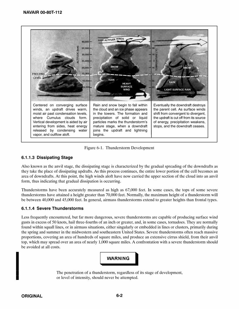
NAVAIR 00-80T-112
ORIGINAL 6-2
Centered on converging surfacewinds, an updraft drives warm,moist air past condensation levels,where Cumulus clouds form.Vertical development is aided by airentering from sides, heat energyreleased by condensing watervapor, and outflow aloft.
Eventually the downdraft destroysthe parent cell. As surface windsshift from convergent to divergent,the updraft is cut off from its sourceof energy, precipitation weakens,stops, and the downdraft ceases.
Rain and snow begin to fall withinthe cloud and an ice phase appearsin the towers. The formation andprecipitation of solid or liquidparticles marks the thunderstorm’smature stage, when a downdraftjoins the updraft and lightningbegins.
Figure 6-1. Thunderstorm Development
6.1.1.3 Dissipating Stage
Also known as the anvil stage, the dissipating stage is characterized by the gradual spreading of the downdrafts asthey take the place of dissipating updrafts. As this process continues, the entire lower portion of the cell becomes anarea of downdrafts. At this point, the high winds aloft have now carried the upper section of the cloud into an anvilform, thus indicating that gradual dissipation is occurring.
Thunderstorms have been accurately measured as high as 67,000 feet. In some cases, the tops of some severethunderstorms have attained a height greater than 70,000 feet. Normally, the maximum height of a thunderstorm willbe between 40,000 and 45,000 feet. In general, airmass thunderstorms extend to greater heights than frontal types.
6.1.1.4 Severe Thunderstorms
Less frequently encountered, but far more dangerous, severe thunderstorms are capable of producing surface windgusts in excess of 50 knots, hail three-fourths of an inch or greater, and, in some cases, tornadoes. They are normallyfound within squall lines, or in airmass situations, either singularly or embedded in lines or clusters, primarily duringthe spring and summer in the midwestern and southeastern United States. Severe thunderstorms often reach massiveproportions, covering an area of hundreds of square miles, and produce an extensive cirrus shield, from their anviltop, which may spread over an area of nearly 1,000 square miles. A confrontation with a severe thunderstorm shouldbe avoided at all costs.
The penetration of a thunderstorm, regardless of its stage of development,or level of intensity, should never be attempted.

NAVAIR 00-80T-112
ORIGINAL6-3
6.1.2 Thunderstorm Weather
6.1.2.1 Precipitation
Liquid precipitation may be ascending, if encountered in a strong updraft; it may be suspended, seemingly withoutmotion, yet extremely concentrated; or it may be falling to the ground. Rain is found in almost every case below thefreezing level. The greatest incidence of heavy rain occurs in the middle and lower levels of the storm. Frozenprecipitation is found in the form of snow and hail. The maximum frequency of moderate to heavy snow occursseveral thousand feet above the freezing level. Snow, mixed in many cases with supercooled rain, may be encounteredin updraft areas at all altitudes above the freezing level. This type of action will cause wet snow to become packedon the leading edge of the aircraft wings, resulting in the formation of rime ice. Hail, if present, is most often foundin the mature stage and it is normally found at more than one or two levels within the cell. The maximum occurrenceof hail is at middle levels.
6.1.2.2 Turbulence
Within the thunderstorm cell, there is a definite correlation between turbulence and precipitation. The intensity ofturbulence, in most cases, varies proportionately with the intensity of the precipitation.
6.1.2.3 Icing
This phenomenon may be encountered at any level where the temperature is below freezing. Both rime and clear iceoccur, with rime predominate in regions of snow and mixed rain and snow, and clear ice more predominant at levelswhere supercooled water droplets (temperature of −4 to −8 °C) are present. As the freezing level is also the zone ofstrongest precipitation and turbulence, this altitude is considered to be the most hazardous.
6.1.2.4 Lightning
There are four types of lightning associated with thunderstorms: (1) cloud to ground, (2) cloud to cloud, (3) clouddischarges (lightning that takes place within the cloud), and (4) air discharges (discharges that pass from the cloudto the air, but do not strike the ground or reach to another cloud). Lightning will occur in, near, or over the top of astorm area, and has been known to strike objects as far as 35 miles from the convective cell.
6.1.3 Thunderstorm Classification
All thunderstorms are similar in their physical makeup. Their classification is based on the type of weather situationthat generates them; therefore, there are two basic classifications of thunderstorms: airmass or frontal.
6.1.3.1 Airmass Thunderstorms
These thunderstorms are subdivided into several types.
6.1.3.1.1 Convective Thunderstorms
Convective thunderstorms are a form of airmass thunderstorm that may occur over land or water almost anywherein the world. They are generated within a large airmass of moist, unstable air. Their formation is caused by solarheating of various areas of the land or sea, which in turn provides heat to the air above. The type of convectivethunderstorms that forms over land normally develops during the afternoon hours and usually begins to dissipateduring the early evening hours. These thunderstorms are usually scattered over a broad area; however, thesethunderstorms have been known to form in large groups (clusters), especially where a unique topographical featureis present. Convective thunderstorms also form over bodies of water in the same manner as those over land, exceptthey form during the evening hours and dissipate by late morning. The coastal areas of Florida, Cuba, and thePhilippines are perfect examples of areas where both the land and water area types of convective thunderstorms arecommon.

NAVAIR 00-80T-112
ORIGINAL 6-4
6.1.3.1.2 Orographic Thunderstorms
Orographic thunderstorms are triggered when the air is lifted over terrain that slopes upward, such as mountains andhills. This type of thunderstorm forms on the windward side of the topographical feature and at times may form a longunbroken line of storms that will be similar to a cold front. Orographic thunderstorms will persist as long as thecirculation continues to produce an upslope motion. When approaching from the lee side, an orographic barrier alongwhich thunderstorms are developing, the outline of each storm is normally plainly visible; however, whenapproaching from the windward side, it may be difficult to identify storms or individual cells because they may beobscured by other clouds. Orographic thunderstorms, almost without exception, will enshroud mountain peaks orhills.
6.1.3.2 Frontal Thunderstorms
These thunderstorms are associated with either warm, cold, occluded, or stationary frontal systems.
6.1.3.2.1 Warm Front Thunderstorms
The warm front thunderstorm is caused when warm, moist, unstable air is forced aloft over the colder (denser),retreating air. Warm front thunderstorms are generally scattered and they are difficult to identify because they arefrequently embedded within other cloud layers. The use of radar is extremely helpful when dealing with warm frontthunderstorms.
6.1.3.2.2 Cold Front Thunderstorms
The cold front thunderstorm is caused by the forward motion of a wedge of cold air into a body of warm, moist,unstable air. This type of thunderstorm is normally positioned along the frontal surface in what appears to be acontinuous line. Cold fronts normally have rapid movement and a steep frontal slope. Although the line ofthunderstorms is relatively narrow, 50 to 100 miles wide, the line may extend for hundreds of miles with scarcely abreak between the cells. The density of these storms presents a serious hazard to aviation operations. In a few cases,squall lines may be associated with cold fronts, and more frequently with fast-moving cold fronts.
6.1.3.2.3 Occluded and Stationary Fronts
Thunderstorms are also encountered with occluded and stationary fronts. The occluded front is actually a combinationof a cold front and a warm front. When penetrating such a weather system, the pilot can expect to experience weatherpatterns synonymous with both types of fronts. The most severe weather associated with an occluded front is normallyfound near the apex of the system (the point where the cold front meets the warm front at the surface). Whenever thissituation exists, the flight should be planned to avoid this area, if at all possible.
6.2 SQUALL LINES
Squall lines (Figure 6-2) are generally associated with fast-moving cold fronts. They are a line of prefrontalthunderstorms that develop when surface friction retards the forward motion of the cold air at the surface to an extentthat the cold air aloft is advanced many miles ahead of the surface front; therefore, this action causes the warm airahead of the front to rise at a greater distance ahead of the front. Squall lines will normally form at ranges from 50to 100 miles in advance of a cold front. These systems are very violent, produce widespread low cloudiness, andsupport the development of tornadic activity.
6.3 TORNADOES AND WATERSPOUTS
A tornado (Figure 6-3) may occur in association with severe squall line conditions. A tornado is a violent whirlpoolof air with an average diameter of approximately 250 yards. Within its funnel-shaped cloud, winds are estimated at100 to more than 300 knots, making it the most violent of all storms. Not only is it small in area, but usually it wearsitself out in an hour. Nobody has ever flown into a tornado and survived.

NAVAIR 00-80T-112
ORIGINAL6-5
Figure 6-2. Squall Line Thunderstorms
Figure 6-3. A Tornado

NAVAIR 00-80T-112
ORIGINAL 6-6
Waterspouts (Figure 6-4) are much the same, but waterspouts occur over the ocean and contain much moisture,whereas the tornado contains much dust and debris from the surface.
6.4 TURBULENCE
6.4.1 Mountainous Terrain
Flight in mountainous terrain must take account of altimeter errors, turbulence, thunderstorm development, andfrontal modifications over large continental ridges. The following factors must also be considered during flight overmountainous terrain:
1. Windward approach — An aircraft approaching a ridge from windward is lifted over the ridge by the airstreamblowing up the slope.
2. Leeward approach — An aircraft approaching a ridge while flying into the wind will experience difficulty inmaintaining altitude in the downdraft and eddies on the leeward slopes.
3. Eddy pattern — In rough, mountainous terrain, the complex eddy pattern will cause turbulence. The amountof turbulence will increase with the windspeed and the roughness of the terrain.
Extreme caution should be exercised for the following factors:
4. Strong winds — Strong winds blowing around and over peaks cause a deflection of the airstream similar tothe flow over the leading edge of an airfoil. Pressure is locally lowered by this distortion of the airstream.
5. Low pressure — An aircraft flying in the low pressure caused by the deflected airstream will have an altimeterindication showing the aircraft considerably above the actual height.
Figure 6-4. A Waterspout
NAVAIR 00-80T-112
ORIGINAL6-7
6.4.2 Clear-Air Turbulence
One of the major hazards to modern, high-performance aircraft is the problem of Clear Air Turbulence (CAT) — arough cobblestone type of bumpiness experienced in cloudless portions of the sky. This bumpiness, occurring withoutvisual warning, may be violent enough to disrupt tactical operations and possibly cause serious aircraft stresses. Theturbulent areas are both patchy in space and variable in time. Most cases of pronounced clear air turbulence can beassociated with the jetstream, or more specifically with abrupt vertical windshears (increases or decreases of windvelocity with altitude), and are experienced more frequently during the winter months when jetstream winds arestrongest. Statistically, this type of turbulence usually occurs with windshears in excess of 8 knots per 1,000 feet.Because of its random and transient nature, exact locations of clear air turbulence are extremely difficult to forecast.
6.5 FOG
Fog is a restriction to visibility caused by moisture condensing in the atmosphere and forming a cloud at the surfaceof the Earth. Fog is reported when the horizontal visibility at an air terminal is reduced to less than 5/8 mile (1kilometer). Fog is formed when the atmosphere is saturated by the air being cooled to the dewpoint temperature orthe addition of sufficient moisture to raise the dewpoint to the temperature of the atmosphere.
Radiation and advection fogs are examples of the former; frontal, steam, and arctic-ice fogs are examples of the lattermeans of saturating the air.
Being formed by different conditions, the various types of fog are characteristically found in particular areas of theworld. The pilot should be aware of the natural processes working in his/her area that could result in fog formationand dissipation.
Although fog often forms very quickly and can cover large areas, formation is seldom without warning. The pilot mustbe alert for the indicators that foretell the formation of fog. He/she must also recognize the more vexing and dangeroussituation when fog has not formed, though conditions are favorable for its imminent formation. This situation isprecarious because the tendency may be to ignore the potential hazard that ceiling and visibility could very quicklygo from that which is completely adequate for normal operations to zero-zero. The general indicators for the pilotto carefully watch for fog formation are dewpoint spread and wind direction and speed. The following paragraphscontain a short description of the four primary categories of fog, the conditions necessary for their formation, and theareas in which they are most likely to occur.
NoteWhen filing to an area where fog is present, the pilot should request that theforecaster identify what type of fog condition is present, either advectionor radiation.
6.5.1 Radiation Fog
Radiation fog or ground fog is formed on clear, relatively calm nights when the surface cools by radiating its heatto a deep layer of the atmosphere. If there is sufficient cooling to reduce the air temperature to the dewpoint at thesurface and a very light breeze to stir the saturated air, fog will form. A wind of more than 8 knots will stir the air toa greater depth and inhibit the formation of fog, although it may lead to the formation of low stratus clouds. Cloudcover will also inhibit radiation fog formation by acting as a blanket and keeping the heat of the Earth in the lowerlayers of the atmosphere. This usually prevents the temperature from approaching the dewpoint.
Theoretically, the relative humidity should be 100 percent for the formation of fog, but in actuality it is normallysomething less due to impurities in the atmosphere that absorb moisture at humidities less than saturation. Visibilitywill start to deteriorate at temperature dewpoint spreads of 5 to 8 °F. In industrial areas, fog can form at even greatertemperature dewpoint spreads because of large amounts of the products of combustion in the air, which have a strongaffinity for moisture. In this case, the visibility reduction is actually because of a combination of smoke and fog andis called “smog,” a familiar term in many large cities.

NAVAIR 00-80T-112
ORIGINAL 6-8
Radiation fog normally reaches its greatest intensity shortly after sunrise, which is because of the increased mixingin the lowest layers of the atmosphere by the initial heating of the sun. This same heating will normally dissipate thefog within 1 to 4 hours after sunrise.
6.5.2 Advection Fog
Advection fog is formed when moist air moves over a surface that is cool enough to reduce the temperature in thelower levels of the airmass to the dewpoint. This type of fog is often found in coastal regions and can blanket verylarge geographic areas. An example is the winter fogs over the eastern United States formed by Gulf air moving northover progressively cooler land. These fogs have at times virtually stopped all aircraft operations east of the MississippiRiver.
Advection fogs are common over land areas during the late winter months along the receding edge of the continentalsnow cover. In these areas, the melting of the snow maintains a temperature of 32 °F at the surface; thus, warm airmoving northward over the snow is both cooled and saturated, forming fog.
Both the North Atlantic and North Pacific have large areas often covered by advection fogs where warm, moist airmoves out of the regions of subtropical high pressure across cool Arctic Ocean currents. The most common areas forthese sea fogs are off the maritime provinces of Canada and near the Aleutian Islands. Unlike radiation fog, whichis normally dispersed by wind greater than 10 knots, the density of advection fog will often increase with increasingwindspeeds. This is especially true of sea fogs, which can persist for long periods with winds of 40 knots or greater.
Another type of advection fog is upslope fog. This type of fog is common along the windward slopes of mountainranges and in some cases can be produced by rather modest topography. It is formed when gently moving moist airis forced aloft by the topographic slope of the land and is cooled to condensation. The altitude at which the fog formsis a function of the temperature dewpoint spread. The wider the dewpoint spread, the farther up the slope the fog willform.
NoteForecasting the dissipation of advection fog is extremely difficult, even forthe most seasoned forecaster; therefore, pilots should ensure that whendealing with a situation that involves advection fog, whenever possible, theaerodrome selected as the alternate field should be outside the geographicarea being influenced by the advection fog.
6.5.3 Frontal Fog
Frontal fogs are a result of precipitation falling from the warm air aloft through the wedge of cold air and saturatingit by evaporation. In the case of a warm front, where most of the weather precedes the passing of the surface front,it is called prefrontal fog. This type of fog can precede the surface front by as much as 200 miles, although it is usuallymuch less. Postfrontal fog follows a surface cold front and, again, is the result of precipitation evaporating in thewedge of cold air, causing saturation. Due to the narrow band of weather normally associated with a cold front,postfrontal fogs are much less common than prefrontal fog.
6.5.4 Arctic Fog
Two types of fog are common to arctic regions: steam fog and ice fog. Steam fog, often called sea smoke, forms whenvery cold air blows over warmer water in the presence of an inversion aloft. Moisture evaporating from the water isimmediately condensed by the cold air and it takes on the appearance of wisps of smoke. Sea smoke can become quitedense and reach altitudes as high as 500 feet. The principal hazard to aviation caused by sea smoke occurs when itis formed in the vicinity of carrier operations or near a land area where it can be advected over an airfield.
Ice fogs form in the regions of the Arctic and Antarctic ice cap under very cold temperatures. They are caused bymoisture changing directly into ice crystals and remaining suspended in the atmosphere. Many ice fogs form around

NAVAIR 00-80T-112
ORIGINAL6-9
regions of human habitation during periods of very light winds when the products of combustion and melted snowact as a moisture source. Ice fogs can also form as a result of moist air being advected into an arctic region. Thesefogs can cover a large geographic region and have been known to extend to altitudes as high as 8,000 feet.
6.6 AIRCRAFT ICING
Aircraft icing creates many hazards to the safe operation of aircraft. Ice on the airframe can alter or destroy theeffectiveness of airfoils, load an aircraft beyond its weight-carrying ability, reduce the effectiveness ofcommunications antennae, create serious cockpit visibility problems, and introduce large errors in airpressure-actuated flight instruments. Structural icing occurs only in clouds or precipitation. Engine icing can occurin clear air as well as in the clouds. Under certain conditions, it can reduce the available power output of either turbineor piston engines and, in some cases, cause their complete failure. Because of the different conditions under whichthey form, structural icing and engine icing will be treated separately.
6.6.1 Structural Icing
Structural icing will only form when two conditions are met: the aircraft must be flying through liquid moisture inthe form of clouds or precipitation, and the temperatures must be below freezing. Structural icing is possible in thetemperature range between 0 and −40 °C; however, very little icing occurs at the colder temperature due to theinfrequent occurrence of supercooled water droplets at those temperatures. Structural icing occurs most frequentlybetween 0 and −17 °C, with the majority of cases falling in the temperature range between −3 and −12 °C. Avoid flyingin clouds at those temperatures. There are three basic types of structural ice: rime ice, clear or glaze ice, and frost.The rate of accumulation and the type of ice collected are dependent on many conditions.
6.6.1.1 Rime Ice
Rime ice is the result of many small, supercooled moisture droplets freezing instantly as they strike an aircraft andforming a milky white agglomeration of small ice particles. It is usually porous and brittle and collects on any partof the aircraft that offers an impact area to particles in the airstream. This includes the leading edge of airfoils, thenose and windscreen of the aircraft, propellers and prop hubs, antennae, and even rivet heads. Rime ice is mostcommonly encountered in stable clouds containing small, supercooled water droplets. It is also formed in unstableclouds at temperatures colder than −15 °C.
6.6.1.2 Clear Ice
Clear ice is a mass of clear, solid ice. It is far more dangerous than rime ice because of its greater weight, the difficultyof removing it, and its tendency to spread along the skin of the aircraft beyond the operating areas of deicingequipment. Clear ice forms when the aircraft encounters large water droplets under subfreezing conditions in unstable(cumuliform) clouds. The larger droplets do not freeze instantly as in rime ice formation, but spread back across theairfoils and fuselage as they freeze, causing the buildup of a large mass of solid ice.
Clear ice can also form as a result of freezing rain. This occurs when cold air is overlain by warm air (as in a warmfront) and rain falls into freezing temperatures. When the rain strikes the cold surface of an aircraft, it spreads, cools,and freezes, adhering to the surface. Freezing rain is one of the most hazardous conditions encountered in aviationand should always be avoided. If a pilot finds him/herself encountering freezing rain he/she should, as soon aspossible, climb to a higher altitude into the warmer air above.
The most common temperature range for the formation of clear ice is between 0 and −8 °C. Under certain conditions,at temperatures below −8 °C in unstable clouds, a mixture of clear and rime ice will form on the airframe.
6.6.1.3 Frost
When encountered in flight, frost is only considered a hazard in that it restricts visibility by covering the windscreenand windows of the aircraft. Frost is somewhat more of a hazard on the ground. A light coating of frost, thoughseemingly insignificant, can sufficiently disrupt the airflow over wings and control surfaces to alter the takeoffcharacteristics of an aircraft. A takeoff should never be attempted under such conditions.

NAVAIR 00-80T-112
ORIGINAL 6-10
The rate of ice accumulation on an aircraft is dependent on several factors: the temperature, the liquid moisturecontent of the air, the airspeed, and the airfoil shape. The relationship between icing rate and liquid water content ofthe air is obvious. The higher the water content, the greater the ice accumulation rate. The same holds true for airspeed.A higher airspeed causes the aircraft to encounter a greater amount of moisture in a given period of time, resultingin a greater ice accumulation rate. Although the rate of ice accumulation is less at low airspeeds, the underside areaof the aircraft exposed to moisture particles is greatly increased because of the increased angle of attack required forslow flight; thus, in very slow flight at high angles of attack, the aircraft may actually pick up a greater load of icethen at cruising airspeeds where the angle of attack is slight and only the leading edge of airfoils and fuselage isexposed to ice accumulation.
The airfoil shape determines deflection characteristics. A thick airfoil found on most propeller-driven aircraft willcause a large deflection in the air passing the airfoil. This in turn deflects much of the moisture around the leadingedge. A thin airfoil, more common to jet aircraft, causes only a small deflection in the air passing it; hence, the waterdrops are much more likely to impinge on the leading edge. Fortunately, for jet aircraft, most icing occurs in the lowerand middle flight altitudes, and only a small percentage at jet cruising levels. The principal icing danger to jet aircraftoccurs during approach and landing.
6.7 STRUCTURAL DEICING
The following discussion is general in nature. In all cases of discussion of techniques, the NATOPS procedures forthe aircraft in question should be followed. Most aircraft are equipped with means either to prevent or remove icefrom critical areas of the aircraft. These areas are the leading edge of airfoils, radomes, propellers, windshields, andthe pitot-static air system. Notable exceptions to this rule are attack and fighter-type jet aircraft and most trainingaircraft. The design of high-performance jet aircraft is not readily adaptable to deicing gear, and in the normaloperation of this type of aircraft, little time is spent at the lower, more potential icing altitudes.
NotePreventive icing systems are not designed to remove ice and should be usedwhen icing is anticipated.
6.7.1 Airfoil
Airfoil deicing is accomplished by inflatable boots. Between 1/4 and 1/2 inch of ice is allowed to build up on the bootprior to inflating it to break the ice off. The inflation cycle, once activated, is automatic to give the optimum breakingaction. If the boot is activated with less than 1/8 inch of ice, the ice sometimes breaks up in small pieces, some of themadhering to the boot and collecting further ice that cannot readily be removed.
Hot wing anti-icers deliver heat to the leading edge of wings and empennage to prevent ice formation. Airfoil heatersmay be activated prior to entry into icing conditions to be used effectively as an anti-icing system. If operated aftera significant amount of ice has accumulated, the airfoil heaters will often only melt a cavity under the ice. The air (orwater vapor) in this cavity acts as an insulator and prevents the heat from melting further ice, rendering the anti-icingsystem ineffective. Some aircraft must use airfoil heaters as a deicing system because of a problem of runback ofmelted ice off the leading edge, which could freeze farther back on the airfoil surface, or possibly build up on flapand control surfaces, which have no anti-ice/deice capability. In these aircraft, the procedure is to let a certain amountof ice build up and then heat the leading edge, loosening the inner layers of ice and allowing the airstream to blowthe ice off the leading edge.
6.7.2 Propeller
Propeller anti-icing is accomplished by electrically produced heat on the leading edge or alcohol that is sprayed onthe base of the propeller and forced out along the leading edge by centrifugal force. Both systems are designed to bepreventive but can serve to remove ice if necessary. Propeller ice can seldom be identified visually except on the prophub; however, its presence may be inferred by the formation of ice on other parts of the aircraft and by vibration fromunbalanced propellers.

NAVAIR 00-80T-112
ORIGINAL6-11
6.7.3 Pitot-Static/Angle of Attack (AOA) Systems
The pitot-static and Angle of Attack (AOA) systems are anti-iced by electric heating elements in the pitot tube or AOAprobe that provide sufficient heat to prevent the formation of ice, or melt ice that has already formed. Static ports arenormally located in areas of the fuselage where the formation of ice is unlikely and where there is no deicing system.Some aircraft are equipped with an alternate static air inlet in case there is a failure of the static air system.
6.7.4 Structural Icing Precautions
The following procedures are recommended when structural icing is encountered or expected:
1. Avoid prolonged operations in weather conditions that could lead to the formation of structural ice. Monitorthe outside air temperature gauge.
2. Increase airspeed when climbing or descending through icing conditions. This accomplishes a threefoldpurpose: It decreases the length of time spent in icing conditions; the decreased angle of attack reduces iceaccumulation on the underside of the airfoils, control surfaces, and fuselage; and the increased speed isnecessary during approach and landing due to the increased stall speed caused by an ice buildup.
3. Do not lower flaps or landing gear until needed. Ice collects rapidly on flaps and landing gear. This adds to theweight of the aircraft and can possibly cause structural damage if the flaps or landing gear are retracted whencovered with ice.
4. Keep controls moving to keep ice from jamming the control surfaces. This is also true of trim tabs andgovernors. Both should be cycled occasionally to ensure they remain free.
5. Climb to escape freezing rain.
6. Sleet particles are frozen raindrops that indicate a layer of freezing rain above. In sleet, it it best to maintainaltitude, as sleet will not adhere to the aircraft.
7. After takeoff from a slush- or snow-covered runway, either leave the landing gear extended or recycle themto alleviate the possibility of the landing gear freezing in the wheel wells.
6.7.5 Aircraft Engine Icing
6.7.5.1 Turbine Icing
Turbine engines, whether prop or pure jet, are subject to structural ice that obstructs engine air intakes. This reducesthe volume of air available to the engine and shows up on the instrument panel as a loss in rpm and an increase inexhaust gas temperature or a loss of power. The conditions that lead to jet engine intake icing are the same as thosethat cause other structural icing, as described in previous paragraphs.
When in icing conditions in jet aircraft, and a combination of Exhaust Gas Temperature (EGT) rise and rpm drop isnoted, suspect engine icing and land at the nearest suitable airfield. Refer to the appropriate NATOPS flight manualfor the type of anti-icing/deicing equipment used.
6.8 LOW-LEVEL WINDSHEAR
In the past, low-level windshear has been proven as the cause of several major mishaps as documented by flight datarecorders. Windshear is defined as a change in wind direction and/or speed over a relatively short distance in theatmosphere. As the atmosphere is very dynamic, pure speed shears or pure directional shears are rare; most shearsinvolve a change in both direction and speed. A common result of this phenomena is known as clear air turbulence.

NAVAIR 00-80T-112
ORIGINAL 6-12
Low-level windshear is defined in the same manner stated above with the exception that it relates to the atmospherebelow 1,500 feet AGL. Low-level windshear can adversely affect an aircraft performance during the landing andtakeoff phases of flight.
An aircraft experiences hazardous low-level windshear when the change in direction or speed takes place faster thanthe airplane can accelerate or decelerate to compensate for the change in forces.
Low-level wind shear is categorized into two types: convective and nonconvective.
6.8.1 Convective Windshear
This phenomena is produced by downdrafts spreading outward from the bottom of a cumulonimbus cloud. The mostcommon type of this windshear is the first gust front associated with thunderstorms, which will normally extendoutward to 10 to 15 miles. The speed of the first gust is normally the highest gust recorded during storm passage. Thewind direction in a first gust can vary as much as 180° from the previously prevailing surface wind. First gustwindspeeds in excess of 75 knots have been recorded. In nearly all cases, forecasters are readily capable of accuratelyforecasting this phenomena, however, there are other types of convective windshear, such as microbursts anddownbursts, which are less frequent, nearly impossible to forecast, yet are capable of producing far more severeconditions. These phenomena are discussed in paragraph 6.9.
6.8.2 Nonconvective Windshear
Development of this type of shear is related to synoptic patterns, major topographical features, or local terrain.Examples of situations that produce nonconvective windshear are (1) frontal shear; (2) low-level jets caused byradiation inversions; (3) funnelling, which may be induced by local terrain or, in some cases, surface obstructions suchas large hangars; (4) land and sea breezes; and (5) mountain waves.
As there is no existing instrumentation that will effectively detect and measure windshear, there are no foolproofprocedures for forecasting this phenomena within an acceptable level of accuracy. The disastrous effect windshearcan have on aircraft during the approach and departure phases of flight cannot be overly stressed. Increasedmonitoring of cockpit indicators, whenever the potential for shear exists, is the most prudent procedure to follow.
The best indication that an aircraft is experiencing low-level windshear is a fluctuation in Indicated Airspeed (IAS)and the rate of descent/ascent. The relationship is a simple one; for example, if a decrease in airspeed is experiencedduring approach, then the Vertical Speed Indicator (VSI) rate of descent will increase; if a decrease in airspeed occursduring takeoff, then the rate of ascent decreases. The converse is true for increases of airspeed. The best rule of thumbis that whenever strong surface winds or convective activity is present, the pilot can expect to encounter some typeof shear situation.
6.9 MICROBURSTS
By definition, a microburst is a small-sized downburst of air from the base of a cumulonimbus cloud that is capableof producing peak winds of more than 135 knots. Microbursts will normally last for 2 to 5 minutes. Some microburstsoccur as large-scale downbursts. These are called macrobursts. An intense macroburst will often cause widespreadtornado-like damage, last for a period of 5 to 20 minutes, and produce a peak wind in excess of 135 knots.
There are no set patterns associated with the development or occurrence of microbursts. Not all severe thunderstormsproduce microbursts; likewise, some small-to-moderate thunderstorms have produced this phenomena. The mostrecent theory on how microbursts occur is that the high pressure dome at the center of the downburst is surroundedby a low pressure ring toward which the outward flowing winds are accelerated (Figure 6-5).
Microbursts may either be wet (associated with heavy rainfall) or classified as dry, when only virga (rain evaporatingprior to reaching the surface) is present.

NAVAIR 00-80T-112
ORIGINAL6-13/(6-14 blank)
Figure 6-5. Profile of a Microburst
Research in the area of microbursts indicates there are some visual indicators that frequently occur when a microburstis taking place. These indicators are virga (a pronounced rain shaft reaching the ground), dust rings (circular areasof dust near convective activity), or lines of cumulus clouds spreading outward from the convective activity. The factthat there are no proven observation or forecasting methods available to predict microbursts cannot be overly stressed.In most cases, the presence of a microburst is not detected until it actually occurs.
From the cockpit of an aircraft, a microburst may look like a local shower, either light or heavy in intensity; however,there is no proven method by which the pilot can visually determine that a microburst will take, or has taken, place.When an aircraft is approaching an area of convective activity, at or below the base of the clouds, the pilot shouldlook for an unusual increase in the airspeed and lift (increase in altitude) of the aircraft, which will indicate the onsetof the microburst. If this scenario takes place, the pilot must take prompt and appropriate measures to deal with therapid onset of a downflow, tailwind, crosswind, or a combination of said elements.
Microbursts pose a serious threat to aircraft, especially those conducting thearrival or departure phase of flight, or operating at low altitudes adjacentto areas of convecting activity. The rapid onset of dangerous downflow andtailwind shear must be met with quick responsive action by the pilot. Theonly safe way to deal with a microburst is to avoid flying in areas wheremicrobursts may develop. Specifically, pilots should delay takeoffs,approaches, and/or landings when operating near convective activity untilthe convective activity has moved safely away from the flightpath.

NAVAIR 00-80T-112
ORIGINAL6-1/(6-2 blank)

NAVAIR 00-80T-112
ORIGINAL71/(72 blank)
PART III
Physiology of Instrument Flight
Chapter 7 — Introduction to Instrument Flight Physiology
Chapter 8 — Spatial Disorientation
Chapter 9 — Factors That Increase the Potential for Spatial Disorientation
Chapter 10 — Medications, Alcohol, and Nutrition
Chapter 11 — Prevention of Spatial Disorientation
Chapter 12 — Overcoming Spatial Disorientation

NAVAIR 00-80T-112
ORIGINAL1/(2 blank)

NAVAIR 00-80T-112
ORIGINAL7-1
CHAPTER 7
Introduction to InstrumentFlight Physiology
7.1 GENERAL
Spatial disorientation is a condition that exists when a pilot does not correctly perceive his/her position, attitude, ormotion relative to the Earth. During flight, the sense of sight is used to determine the aircraft attitude in relation tothe surface of the Earth. In visual flight conditions, aircraft attitude is determined by reference to the horizon of theEarth and flight instruments. During instrument flight conditions when the horizon is not visible, aircraft attitude mustbe determined by reference to the aircraft attitude indicator and other flight instruments. Under instrument flightconditions, the visual sense may disagree with supporting senses, resulting in a conflict between what the pilot seeson his/her flight instruments and what he/she “feels” his/her attitude in space to be. It is this conflict that may leadto spatial disorientation and loss of aircraft control.
Sensory illusions can occur regardless of the pilot’s experience or proficiency; however, the effects of spatialdisorientation may be decreased, provided the pilot believes his/her instrument indications and maintains proficiencyin instrument flight. In addition, an understanding of the physiological basis of various illusions, the flight conditionswhere these illusions may be expected, and ways to prevent or overcome an episode of spatial disorientationeffectively is of great importance.
7.2 YOUR SENSES
The ability to maintain equilibrium and orientation depends on sensations or signals from three sources. Thesesensations come from the motion-sensing organs of the inner ear (vestibular system); the postural senses of touch,pressure, and tension (proprioceptive system); and the sense of sight. In the absence of good visual references, theability to maintain equilibrium and orientation based on the other senses is markedly reduced.
The three sensory systems function adequately for normal earthbound activities, but when a person is subjectedto the flight environment, these organs may relay false information, resulting in spatial disorientation or vertigo(Figure 7-1).
7.2.1 Motion (Inner Ear)
The sense of motion originates in the inner ear. The motion-sensing organs are the otolith organs and semicircularcanals (Figure 7-2).
7.2.2 Semicircular Canals
The semicircular canals register rotational acceleration. They can detect turns, slips, and skids during flight.
This organ consists of three canals oriented at right angles to each other so that angular accelerations in the pitch, yaw,and roll planes can be detected. The canals are filled with fluid that moves when angular accelerations are appliedto the head. The movement bends the sensory hairs, which result in nerve impulses being sent to the brain. The pilotinterprets this as rotary motion. If the fluid catches up to the canal walls, such as in a prolonged turn, the sensory hairsare no longer bent and no motion is perceived. Also, very small or short-lived angular accelerations may not beperceived; thus, patterns of acceleration experienced in flight are different from those experienced on the ground. Thiscan result in an erroneous perception of position in flight (Figure 7-3).

NAVAIR 00-80T-112
ORIGINAL 7-2
Figure 7-1. Senses Used for Maintaining Equilibrium and Orientation
Figure 7-2. The Inner Ear

NAVAIR 00-80T-112
ORIGINAL7-3
Figure 7-3. Semicircular Canals

NAVAIR 00-80T-112
ORIGINAL 7-4
7.2.3 Otolith Organs
The otolith organs are stimulated by linear accelerations or gravity force. These organs consist of sensory hairsprojecting into a gel on which rest small crystals (otoliths). When the head is tilted with respect to gravity, the crystalsmove and bend the hairs, creating the sensation of tilting the head or body in relation to the true vertical (gravity).During flight, inertial forces are combined with the force of gravity. The resultant force that acts upon the otolith organis almost never the direction of the true vertical. The brain monitors this and determines which way is “down”;therefore, the brain will be deceived much of the time in flight (Figure 7-4).
7.2.4 Postural (Seat of the Pants)
The postural sense derives its sensations from the expansion and contraction of muscles and tendons and from touchand pressure. This is the so-called seat-of-the-pants sense not considered reliable in flying. A greater increase in thispressure occurs in climbing, and any maneuver that produces pressure against the seat may be interpreted as climbing;therefore, without visual aid, this sense often interprets centrifugal force as a false climb or descent. Without visualreference to the natural horizon or flight instruments, a steep turn could be interpreted as a steep climb and a shallow,descending turn could be perceived as straight-and-level flight; therefore, the postural senses, like those of the innerear, are unreliable without visual aid. Pilots are aware that they cannot fly by feel alone but must subordinate thesefalse sensations to their flight instruments (Figure 7-5).
Figure 7-4. Otolith Organs
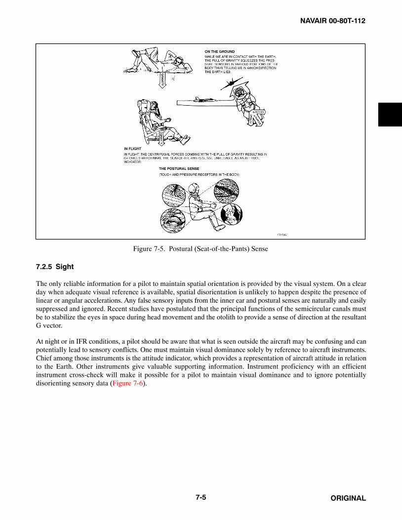
NAVAIR 00-80T-112
ORIGINAL7-5
Figure 7-5. Postural (Seat-of-the-Pants) Sense
7.2.5 Sight
The only reliable information for a pilot to maintain spatial orientation is provided by the visual system. On a clearday when adequate visual reference is available, spatial disorientation is unlikely to happen despite the presence oflinear or angular accelerations. Any false sensory inputs from the inner ear and postural senses are naturally and easilysuppressed and ignored. Recent studies have postulated that the principal functions of the semicircular canals mustbe to stabilize the eyes in space during head movement and the otolith to provide a sense of direction at the resultantG vector.
At night or in IFR conditions, a pilot should be aware that what is seen outside the aircraft may be confusing and canpotentially lead to sensory conflicts. One must maintain visual dominance solely by reference to aircraft instruments.Chief among those instruments is the attitude indicator, which provides a representation of aircraft attitude in relationto the Earth. Other instruments give valuable supporting information. Instrument proficiency with an efficientinstrument cross-check will make it possible for a pilot to maintain visual dominance and to ignore potentiallydisorienting sensory data (Figure 7-6).

NAVAIR 00-80T-112
ORIGINAL 7-6
THE PILOT MUST RELY ONTHE SENSE OF SIGHT TOINTERPRET FLIGHTINSTRUMENTS PROPERLY.
Figure 7-6. The Sense of Sight

NAVAIR 00-80T-112
ORIGINAL8-1
CHAPTER 8
Spatial Disorientation
8.1 FALSE PERCEPTION (GENERAL)
8.1.1 Illusions: Primarily Inner Ear
Illusions related to the inner ear can result from semicircular canal stimulation (angular motion) and from otolithorgan stimulation (linear motion).
8.1.1.1 The Leans
This is a common illusion and is caused by rolling or banking the aircraft after the pilot establishes a false impressionof the true vertical. In a prolonged turn, the semicircular canals may perceive a roll to wings level as a turn in theopposite direction. This causes pilots to lean in an attempt to assume what they think is a true vertical posture. Shoulda pilot establish a very subtle roll to the left that does not stimulate the semicircular canals and then roll rapidly tolevel flight, the pilot may retain the false impression of only having rolled to the right. Again, the pilot may flyadequately in spite of this illusion, although the pilot may lean to assume a false vertical posture (Figure 8-1).
Figure 8-1. The Leans

NAVAIR 00-80T-112
ORIGINAL 8-2
8.1.1.2 A False Sensation of Rotation (Somatogyral Illusion)
This condition can occur when the semicircular canals are abnormally stimulated by certain turning maneuvers andthe resulting angular acceleration. Examples include the following:
8.1.1.2.1 Graveyard Spin
When the semicircular canals are stimulated by the angular acceleration produced by the spin entry, the firstimpression of the pilot is accurate (i.e., a spin is perceived). After approximately 10 to 20 seconds, the fluid in thecanals reaches a constant speed and the sensing mechanism returns to the resting position, whereupon, the sensationof spinning is replaced by one of no rotary motion despite the fact the spin continues. If the spin is then terminated,an angular deceleration is produced, which acts upon the semicircular canals to cause a sensation of spinning theopposite direction. Suffering from the illusion of spinning in the opposite direction, the pilot may try to correct forthis false impression by putting the aircraft back into the original spin (Figure 8-2).
8.1.1.2.2 Graveyard Spiral
This maneuver is similar to the graveyard spin except the aircraft is in a descending turn rather than a stalled condition.The constant rate of turn causes one to lose the sensation of turning after a period of time. The pilot, noting the lossof altitude, may pull back on the stick or perhaps add power in an attempt to gain the lost altitude. Unless the sinkattitude is first corrected, such actions can only serve to tighten a downward spiral. Once the spiral has beenestablished, the pilot will suffer the illusion of turning in the opposite direction after the turning motion of the aircraftstops. Under these circumstances, the wrong corrective action may be taken, which will result in reestablishment ofthe spiral.
8.1.1.3 Coriolis Illusion
The coriolis illusion is perhaps the most dangerous of the inner ear illusions because it causes an overwhelmingdisorientation of the pilot, which can be extremely dangerous at low altitudes. This reaction is most apt to occur whena pilot is in a constant-rate turn, such as in a penetration turn or holding pattern. When the body is in a prolonged turn,the fluid in those canals that were stimulated by the onset of the turn eventually come up to speed with the canal walls.If the head is then tipped, the angular momentum of the fluid causes it to move again relative to the canal walls. Theresulting sensation is one of rotation in the plane of the new position of the canal even though no actual motion hasoccurred in that plane; thus, abrupt head movements may cause false sensations of angular motion and erroneousperceptions of attitude. An attempt to correct for this is likely to result in a loss of aircraft control. To prevent thisreaction, pilots should avoid sudden extreme head movements, especially while making turns. The head movementoften results in an overwhelming sensation of a roll coupled with a climb or dive. Correction for this apparent unusualattitude should be made on the aircraft attitude indicator and not by reflex action. The solution is simple: minimizehead movement.
8.1.1.4 Nystagmus
Nystagmus often accompanies coriolis illusion. During and immediately after maneuvers resulting from particularlyviolent angular accelerations such as spins and rapid aileron rolls, the eyes can exhibit an uncontrollable oscillatorymovement called nystagmus. This eye movement generally results in an inability to focus either on flight instrumentsor on outside visual references. Rolling maneuvers are especially likely to result in visual blurring because ofnystagmus. Normally, nystagmus ceases several seconds after termination of angular acceleration, but underconditions of inner ear dominance and high task loading, nystagmus and blurring of vision can persist much longer— long enough to prevent recovery.

NAVAIR 00-80T-112
ORIGINAL8-3
Figure 8-2. The Graveyard Spin

NAVAIR 00-80T-112
ORIGINAL 8-4
8.1.1.5 Pressure Vertigo
This condition is also of inner ear origin, although the exact mechanism is not understood. Symptoms include blurringof vision, nystagmus, and illusory sensations of turning. These symptoms occur more commonly and more severelywhen there is an explosive increase in middle ear pressure (e.g., with the Valsalva maneuver), although they can occurwith gradual increases in middle ear pressure (such as with aircraft ascent). Pressure vertigo usually occurs when thereis some difficulty or hesitation in “clearing the ears,” especially if the individual has a cold or flu.
8.1.1.6 Illusion of Attitude Change (Somatogravic Illusion)
This illusion can occur when the otolith organs are abnormally stimulated by linear acceleration. Examples includethe following:
8.1.1.6.1 Illusion of Noseup
This illusion can occur when an aircraft accelerates forward while in level flight and gives the pilot the sensation ofbeing in a noseup attitude. This may occur as a result of a missed approach or during takeoff. The chest-to-spineacceleration experienced by the pilot is vectored with gravity, and the combined gravitational-inertial accelerationvector is increased in length and rotated as the acceleration continues (Figure 8-3). This can generate both visual andpostural illusions. The visual illusion causes objects to appear to rise above their true physical positions, and thepostural illusion causes the pilot to feel that his/her body is being tilted backwards. Because of these illusions, thepilot can become disoriented; the entire array of cockpit instruments may appear to rise, and the pilot may feel thathis/her aircraft is climbing in an excessively high, noseup attitude. If a pilot were to correct for this illusion, he/shemight inadvertently dive the aircraft.
Figure 8-3. Forward Acceleration Illusion of Noseup

NAVAIR 00-80T-112
ORIGINAL8-5
This type of illusion can be extremely dangerous during catapult launching of carrier-based aircraft and deservesspecial mention here. When an aircraft is launched from the deck of a carrier, the pilot is exposed to a sudden anddramatic change in the accelerative forces acting on his/her body. The pilot is pushed sharply back into his/her seatas the aircraft hurtles forward, accelerating rapidly to attain adequate airspeed. Although the acceleration is of briefduration, lasting for only 2 to 4 seconds, it is of sufficient intensity that the pilot may be disoriented during itsapplication and for some time after the catapult launch accelerations have been terminated. The visual impressionof a noseup attitude can lead to control errors, especially on a moonless, starless, black, overcast night when thereis little opportunity for external visual cues to override the illusion; thus, if the pilot was deprived of appropriateinformation concerning the true pitch attitude, the natural tendency would be to reduce the illusory excessive noseupattitude of the aircraft by easing forward on the stick. This could result in a fatal water collision accident (Figure 8-4).
Although flight instruments can help the pilot to overcome disorientation, the value of the instruments dependscritically on how closely they are monitored, how accurately they are interpreted, and how well they provide the pilotwith information needed to control the aircraft. The prescribed technique in instrument flight immediately followinga catapult launching at night is for the pilot to scan the cockpit instruments continuously, making certain that the endairspeed is sufficiently high to support flight, a positive rate of climb is established, the angle of attack and the pitchattitude of the aircraft are appropriate, adequate airspeed is maintained, and altitude is increasing. Instrumentscanning should be continued throughout the entire climbout procedure, and trim, stick, and rudder adjustmentsshould be made to keep all flight variables within general specified limits. Clearly, the pilot’s workload during theclimbout procedure is high, and lapses in performance can hold fatal consequences.
Figure 8-4. Noseup Illusion During Catapult Launch

NAVAIR 00-80T-112
ORIGINAL 8-6
8.1.1.6.2 Illusion of Nosedown
The opposite illusion of nosedown attitude may occur as a result of deceleration (Figure 8-5). If a pilot were to correctfor the illusion of nose-low pitch caused by deceleration on final approach, the corrective action might result in a lowaltitude stall. Although this type of illusion is of greatest magnitude in high-performance aircraft, it can occur in allaircraft. A pilot can readily overcome the illusion by giving attention to distinct, valid references or to flight attitudeinstruments.
8.1.1.6.3 False Perception of Attitude
False perception of attitude can also occur during a flat or coordinated turn. The pilot can equate the sustained resultant(R) with the vertical (gravity); therefore, in a flat turn (Figure 8-6), the pilot may feel as if rolled out of the turn. Ina coordinated turn (Figure 8-7), the resultant is aligned with the pilot’s axis, and there will be no sensation of a bankedattitude.
8.1.1.7 Inversion Illusion
Inversion illusion can occur during an abrupt pushover from a climb into level flight (Figure 8-8). The abrupt aircraftattitude change and consequent negative g force acting on the otolith organs cause a sensation of being inverted.Reflex action can cause the pilot to correct for this illusion by pushing the nose of the aircraft abruptly downward,thus intensifying the illusion.
8.1.1.8 Elevator Illusion
Elevator illusion results from stimulation of otolith organs by an increase in gravity (Figure 8-9). If an upward linearacceleration occurs while the aircraft wings are level, as in a sudden updraft, the pilot’s eyes reflexly move downward.The illusory upward motion of the immediate surroundings can give the pilot the impression that the aircraft isclimbing and cause the pilot to reflexly place the aircraft into a dive.
Figure 8-5. Deceleration Illusion of Nosedown

NAVAIR 00-80T-112
ORIGINAL8-7
Figure 8-6. False Perception of Attitude During Flat Turn
Figure 8-7. False Perception of Attitude During Coordinated Turn

NAVAIR 00-80T-112
ORIGINAL 8-8
Figure 8-8. The Inversion Illusion
Figure 8-9. The Elevator Illusion

NAVAIR 00-80T-112
ORIGINAL8-9
The opposite of the elevator illusion (oculoagravic illusion) can occur during a sudden downdraft. The eyes will reactwith an upward shift, resulting in apparent downward shift of objects interpreted as a nosedown aircraft attitude. Thepilot may react by pulling back on the stick, and enter an unperceived climb.
8.1.2 Visual Illusions and Problems
The aircraft instruments are extensions of the pilot’s senses. As long as the pilot correctly interprets and uses theinstruments when deprived of external visual references, orientation will remain; however, there are certainconditions encountered during VFR and formation flight that may cause confusion, illusions, and spatialdisorientation.
8.1.2.1 Confusion of Ground Lights with Stars
Confusion of ground lights with stars is a common problem associated with night flying (Figure 8-10). Incidents havebeen recorded where pilots have put their aircraft into very unusual attitudes to keep some ground lights abovebecause they believed the lights were stars. Sometimes pilots have mistaken certain geometric patterns of groundlights, such as freeway lights, with runway and approach lights, or assumed a line of ground lights represented thehorizon. In doing so, the possibility exists of flying into the ground because the perceived horizon is below the actualone. Sometimes pilots confuse unlighted areas of the Earth with an overcast night sky. They are likely to perceivecertain ground features such as a seashore as the horizon and fly into the unlighted water or the terrain above it.
8.1.2.2 False Vertical and Horizontal Cues
False vertical and horizontal cues can occur while flying over sloping cloud decks or land that slopes graduallyupward into mountainous terrain (Figure 8-11). Pilots are often compelled to fly with their wings parallel to the sloperather than straight and level. A related phenomenon is the disorientation caused by the aurora borealis, in which falsevertical and horizontal cues generated by the aurora result in attitude confusion in pilots trying to fly formation orrefuel at night in northern regions.
Figure 8-10. Confusion of Ground Lights with Stars

NAVAIR 00-80T-112
ORIGINAL 8-10
Figure 8-11. Sloping Cloud Decks
8.1.2.3 Visual Autokinesis
A stationary light stared at for several seconds in the dark will appear to move (Figure 8-12). This phenomenon cancause considerable confusion in pilots flying formation at night. Increasing the brilliance, size, or number of lights,or causing the lights to flash on and off, will diminish the effect of this phenomenon.
8.1.3 False Perceptions During Helicopter Flights
The problem of illusions in helicopter pilots is not totally understood due to various complicating factors: thefundamental difference between a helicopter and other aircraft, the complexity of its piloting, its instability in flight,and excessive noises and vibrations. All of these probably have definite effects on the pilot’s spatial orientation andat the same time may promote the development of false perceptions.
Poorly developed habits of instrument flying are the most frequent cause of false perceptions, especially during flightswith limited visibility and few definite clouds, when the pilot is distracted from instrument flying and tries to orienthim/herself visually. Illusions develop under conditions hampering orientation in space, such as flights over the seaon moonless starry nights, in calm twilight, or when caught in thickly falling snow. Other factors contributing toillusions are poor rest before flight, fatigue during lengthy flights, indulgence in alcohol on the eve of the flight, andpoor adjustment to instrument flight.
8.1.3.1 Illusion of Banking
This illusion is connected with the persistent tendency of helicopters to bank during flight. The inhibitory processesin the pilot’s brain are intensified under the influence of noise and vibration, especially if the pilot has had insufficientpreflight rest, use of alcohol on the eve of flight, or recent cold or flu. The false perception can hold for a few secondsor as long as 15 minutes.

NAVAIR 00-80T-112
ORIGINAL8-11
Figure 8-12. Visual Autokinesis
When this illusion develops, the pilot should concentrate all attention on the instruments. If the false perception doesnot pass, it is necessary to transfer the control to the copilot and rest awhile. After this, the illusion generallydisappears. In certain instances, the illusion ceases after the helicopter is positioned by the second pilot.
8.1.3.2 Illusion of Deviation
During entry into clouds, or during a flight through occasional clouds, pilots can experience the illusion that thehelicopter deviates from its course. This can occur if the pilot has not completely switched to instrument flying.Oncoming clouds, flowing around the helicopter, swerve to the side, creating the impression that the helicopter isdeviating from the course. As the pilots are seated at the sides of the helicopter, they only see the part of the oncomingcloud flow that bypasses at their side; thus, in pilots sitting at the left, an illusion develops that the helicopter isdiverging to the right, and in the pilots sitting at the right, this deviation seems to be to the left. The illusion can lastfrom 1 to 1.5 minutes and disappears as soon as the pilot completely switches to instruments.
8.1.3.3 Illusion of Pivoting on Longitudinal Axis
Weak instrument technique causes this illusion, which can appear in dense masses of homogeneous clouds. Themotion of an approaching mass of clouds is least marked but, instead, a downward flow directed by the shape of thesupporting structure is distinctly apparent. This creates the impression that the front portion of the helicopter is risingand the tail girder dropping. The helicopter seems to pivot on its longitudinal axis. The pilot feels as if he/she werenot sitting but lying on his/her spine. This illusion lasts for a few seconds to 1 minute. Switching attention completelyto instruments, or the appearance of varied density or illumination of the clouds, brings about cessation of the illusion.

NAVAIR 00-80T-112
ORIGINAL 8-12
8.1.3.4 Illusion of Vertical Flight
This illusion is caused by simultaneous excitation of the receptors of the inner ear and visual analyzers. A change inbody position and simultaneous observations of uniformly moving background (in particular the flow of cloudsdownward from the rotors) give rise to false impressions as to the position and direction of the helicopter. Animpression is created that the helicopter has turned 90° downward on its longitudinal axis and is flying vertically. Thisillusion can appear in pilots at the moment of forward acceleration with the sudden increase in the angle formed bythe horizontal and longitudinal axis of the helicopter (angle of pitch) while the pilot is at the same time watching thedownward flow of the cloud stream from the rotors. With a change of no more than 5° in the angle formed by thelongitudinal axis of the helicopter and the horizontal, the illusory perception of angle change may reach 90°. Theillusion lasts 20 to 30 seconds and disappears completely.
8.1.3.5 Flicker Vertigo
This term refers to the feelings of dizziness that may be accompanied by nausea caused by intermittently flickeringlights. Sources of flickering lights include sunlight through rotor blades, windshield wipers, or reflection ofanticollision lights off clouds. Turning off distracting lights or changing direction may help reduce flicker vertigo.
8.1.3.6 Preventive Measures
The study and awareness of illusions by flight personnel have definite value in prevention. All flight personnel shouldbe acquainted during flight briefings with the flight conditions and the possibility of false perceptions arising duringone or another portion of the flight. If the pilot would be aware beforehand of what might be encountered, this couldhelp forestall illusions. A strict regime of work and rest should be observed. When fatigued during a flight, the pilotshould pass the control to the copilot. Instruments should be trusted and the aircraft flown to make them read correctly.
8.2 SPATIAL MISORIENTATION
Unlike spatial disorientation, spatial misorientation occurs unrecognized by the pilots and aircrew. Spatialmisorientation mishaps are characterized by controlled, 1-G collisions with the ground or obstacles on the ground.Terms that have been used to describe symptoms of spatial misorientation include unrecognized spatialdisorientation, task overload, task saturation, loss of situational awareness, fixation, distraction, or preoccupation.Typically, a pilot who experiences spatial misorientation is mistakenly comfortable with the attitude or flightpath ofthe aircraft, or is distracted from monitoring flight instrument cross-checks. The pilot unconsciously acceptsperipheral visual cues such as outside horizons, cloud banks, etc. for attitude flying, instead of central visual cues suchas cockpit instruments. Factors that prevent or distract a pilot from utilizing central visual cues for cross-checkingflight/attitude instruments are numerous, but are especially present during times of high pilot workload, fatigue, andnight flying. Preflight considerations should take into account the type of mission, anticipated workloads, time of day,etc., which might distract a pilot from using visual cues for cross-checking flight/attitude instruments.

NAVAIR 00-80T-112
ORIGINAL9-1
CHAPTER 9
Factors That Increase the Potential forSpatial Disorientation
9.1 GENERAL
There are a number of factors that will increase the potential for spatial disorientation. Some of these are personalin nature whereas others are external and related to the flying environment and various phases of flight. Pilot andsupervisor awareness may reduce the risks associated with these factors.
The key to success in instrument flying is an efficient instrument cross-check. Any situation or factor that interfereswith this flow of information will increase the potential for disorientation.
9.2 PERSONAL FACTORS
A pilot who is mentally stressed, preoccupied with personal problems, fatigued, ill, or taking unprescribed medicationis at increased risk. A pilot preoccupied with significant family problems may not be able to fully concentrate on thetasks related to flying duties. Any of these factors may be detrimental to an effective instrument cross-check and canadversely affect the pilot’s ability to interpret and process information provided by aircraft instruments.
9.3 ENVIRONMENTAL FACTORS
Certain environmental factors and situations, when the visual system becomes compromised, can reduce a pilot’sability to maintain spatial orientation. Some of these factors include:
1. Weather. In particular, transfer from external visual to instrument cues.
2. Night. Isolated light sources can enhance the probability of sensory illusions. Confusing ground lights withstars can also occur.
9.4 FACTORS RELATED TO TYPE OR PHASE OF FLIGHT
Prolonged linear acceleration or deceleration, prolonged angular motion, subthreshold changes in attitude, or ascentor descent are flight maneuvers that can precipitate an episode of spatial disorientation. Specific types and phases offlight are described in the following paragraphs.
9.4.1 Takeoff and Landing Phases
Spatial disorientation mishaps have occurred after takeoff, in the initial climbout following takeoff, during thepenetration, following a penetration turn, or in the transition to final approach and landing. The takeoff and landingphases of flight are dynamic, demanding environments. Aircraft acceleration, speed, trim requirements, rate ofclimb/descent, and rate of turn are flight parameters undergoing frequent change. The aircraft may pass in and outof Visual Meteorological Conditions (VMC) and Instrument Meteorological Conditions (IMC). At night, groundlights may add confusion. Radio channel or Identification Friend or Foe/Selective Identification Feature (IFF/SIF)changes may be directed during a critical phase of flight while close to the ground. Unexpected changes in climboutor approach clearances may increase workload and interrupt an efficient instrument cross-check. An unexpectedrequirement to make a missed approach or a circling approach at night or in IMC conditions is particularly demanding.At a strange field with poor runway lighting, this may be especially dangerous.

NAVAIR 00-80T-112
ORIGINAL 9-2
9.4.2 ACM or Air-to-Ground Ordnance Deliveries
A critical phase of flight with a high potential for spatial disorientation is the maneuvering associated with Air CombatManeuvering (ACM) or air-to-ground ordnance deliveries during night or periods of reduced visibility. Under suchconditions, the only reliable information related to aircraft attitude is provided by the flight instruments. Because ofthe nature of the mission, the pilot’s attention is directed outside the cockpit. Potential for distraction is great. Failureto scan an important instrument parameter such as bank or pitch attitude, airspeed, or vertical velocity during a criticalphase of the weapons delivery may occur. These factors can lead to spatial disorientation or to a “lack of situationalawareness” in which the pilot inadvertently places the aircraft into a position from which recovery may be impossible.Distraction, lack of situational awareness, and spatial disorientation are not the same, but the root causes of each arerelated (i.e., failure to maintain an effective instrument cross-check). One can lead to the other and any one of the threemay result in a fatal mishap.
9.4.3 Formation Flight
The most critical situation for developing spatial disorientation is night or weather formation flights. Formation flyingcan present special problems to the pilot in maintaining spatial orientation. First and most important, the pilot flyingwing cannot maintain visual dominance during orientation-information processing and is deprived of any reliablevisual information concerning aircraft attitude related to the surface of the Earth. The pilot cannot see the true horizonand has little or no time to scan the aircraft instruments. Under these conditions, it becomes difficult to suppressinformation provided by unreliable sources such as the inner ear. Illusions are almost inevitable. A pilot’sconcentration on maintaining proper wing position may be diverted by what the pilot “feels” the aircraft attitude tobe. Lack of confidence in the lead will increase tension and anxiety. An inexperienced, rough flight lead will mostcertainly aggravate the situation. Poor in-flight communications and the lack of specific procedures (properly briefed)to recover a disoriented wingman will increase the potential for an aircraft mishap.

NAVAIR 00-80T-112
ORIGINAL10-1
CHAPTER 10
Medications, Alcohol, and Nutrition10.1 GENERAL
Self-medication in aviation is a common and potentially dangerous act. With the increasing medical sophisticationof the general public through media advertising, there is a definite possibility of self-diagnosis and self-prescription.Self-medication and taking medicine in any form while flying can be extremely hazardous to a pilot. Even simple,over-the-counter remedies may seriously impair judgment and coordination, adversely affect the pilot’s ability tointerpret and process information provided by aircraft instruments, or produce inner ear effects that may precipitateor intensify experiences of vertigo in aircraft. OPNAVINST 3710.7 series prohibits the use of all drugs by flightpersonnel unless specifically approved by a flight surgeon, aviation medical examiner, or aviation medical officer.
The adverse effects of drugs on the human body are further complicated by the complex interactions that occur inthe body between drugs, between drugs and alcohol, and between drugs and food additives, including caffeine andnicotine. Adverse drug effects are additive but can be synergistic, where the resulting effect is greater than the sumof the individual effects.
The insidious incapacitation that may result from the effects of drugs and alcohol is increased when the pilot isfatigued, frustrated, or in a state of mild hypoxia. In addition, it is an even greater problem when a drug is used overa period of several days, weeks, or even longer. Never take medication before flying except on the advice of a flightsurgeon.
10.2 NUTRITION
All flight and ground support personnel shall be provided a positive program of information for the establishmentand maintenance of good dietary habits. Failure to eat within 12 hours preceding end of flight may impair performanceand ability to control aircraft adequately. Reducing diets should be under strict supervision of a flight surgeon.
10.3 EXERCISE
Planned physical fitness programs promote health. All levels of command are encouraged to establish approvedphysical fitness programs for all personnel in accordance with OPNAVINST 6110.1. Due consideration must be givento avoiding contact sports, skiing, etc. Adequate rest periods must be provided for aviators before flying followingparticipation in competitive or particularly tiring sports activity. Twelve hours should normally be adequate.
10.4 DRUGS
Drugs are defined as any chemical that when taken into the body causes a physiological response. All flight andsupport personnel shall be provided appropriate information by a command drug abuse education program.
1. Legal drugs are those medically prescribed or legally purchased for treatment of illness.
a. Prescription drugs — Taking drugs prescribed by competent medical authority shall be consideredsufficient cause for recommendation of grounding unless their use is specifically approved by a flightsurgeon, or a waiver of specific drug use has been granted by Chief of Naval Personnel or the Commandantof the Marine Corps. Consideration shall be given to the removal of ground support personnel from criticalduties, for the duration of the drug effects, if appropriate. Medicines such as antihistamines, antibiotics,tranquilizers, sleeping pills, etc. obtained by prescription shall be discarded if all are not used during theperiod of medication.
b. Over-the-counter drugs — Because of the possibility of adverse side effects and unpredictable reactions,the use of over-the-counter drugs by flight personnel is prohibited unless specifically approved by a flightsurgeon. Ground support personnel shall be briefed on the hazards of self-medication and should bediscouraged from using such drugs.
NAVAIR 00-80T-112
ORIGINAL 10-2
c. Alcohol — The well-recognized effects (i.e., intoxication and hangover) are detrimental to safe operations.Consumption of any type of alcohol is prohibited within 12 hours of flight planning. Adherence to the letterof this rule does not guarantee a crewmember will be free from the effects of alcohol after a period of12 hours. Alcohol can adversely affect the vestibular system for as long as 48 hours after consuming, evenwhen blood-alcohol content is zero. Special caution should be exercised when flying at night, over water,or in Instrument Meteorological Conditions (IMC). In addition to abstaining from alcohol for 12 hours priorto flight planning, flightcrews shall ensure they are free of hangover effects prior to flight. Detectable bloodalcohol or symptomatic hangover shall be cause for grounding of flight personnel and the restriction of theactivities of aviation ground personnel.
d. Tobacco — Smoking has been shown to cause lung disease and impair night vision, dark adaptation, andincrease susceptibility to hypoxia. Smoking is hazardous to nonsmokers, as the effects occur whether smokeis inhaled directly or secondarily. Persons desiring to smoke shall show due consideration for the desiresof nonsmokers in the vicinity and abstain from smoking if asked. Further guidance on smoking is containedin OPNAVINST 3710.7 series.
e. Caffeine — Excessive intake of caffeine from coffee, tea, cola, etc. can cause excitability, sleeplessness,loss of concentration, decreased awareness, and dehydration. Caffeine intake should be limited to not morethan 450 mg per day, or 3 to 4 cups of coffee.
2. The use of illicit drugs is prohibited.
10.5 ILLNESS
Acute minor illnesses such as upper respiratory infections, vomiting, or diarrhea can produce serious impairment offlight personnel. All illnesses shall be evaluated by competent medical authority. Recommendations for groundingshall be accomplished by the submission of a grounding notice (NAVMED 6410/1). Clearance notices(NAVMED 6410/2) shall be issued only by a flight surgeon. Where a flight surgeon is not available, clearance noticesshall be handled in accordance with BUMEDINST 6410.5. Flight personnel who are hospitalized shall be evaluatedin accordance with BUMED directives and a clearance notice issued prior to flight. Ground support personnel shouldbe similarly monitored. Aircrew shall not fly for at least 48 hours after general, spinal, or epidural anesthetic. Returnto flying status thereafter shall be upon the recommendation of a flight surgeon and at the discretion of thecommanding officer.
10.6 DENTAL CARE
Dental procedures that involve the use of injectable drugs (e.g., novocaine) shall be cause for grounding for a periodof 24 hours.
10.7 IMMUNIZATION/INJECTIONS
Flight personnel shall not participate in flight duties for 12 hours after receiving an immunization or injection unlesscleared sooner by a flight surgeon. Those showing protracted or delayed reaction shall be grounded until cleared bya flight surgeon.
10.8 BLOOD DONATION
Although blood donated in small quantities is quickly replaced and does not adversely affect ground activities, thehazards of hypoxia and reduced barometric pressure make it desirable to limit such donations by flight personnel inaccordance with the following:
1. Flight personnel shall not be regular blood donors.
2. Flight personnel in combat or flying in a shipboard environment shall not donate blood within 4 weeks priorto such flying.
3. Flight personnel shall not participate in flight duties or perform low-pressure chamber runs for 4 days followingdonation of 450 cc of blood (1 pint).

NAVAIR 00-80T-112
ORIGINAL11-1
CHAPTER 11
Prevention of Spatial Disorientation
11.1 GENERAL
In the prevention of spatial disorientation, there are primarily two aspects: training and experience.
11.2 TRAINING
The training aspect includes lectures and reading material on the unreliability of bodily senses in flight and factorsfavoring disorientation. Most important are the training and qualifications of learning to fly by instruments andmaintaining proficiency in instrument flight.
Training in controlled spatial disorientation situations is also helpful. A number of maneuvers can be used todemonstrate spatial disorientation. Each maneuver normally creates a specific reaction; however, any reactionresulting in a false sensation is effective. The purpose of these maneuvers is to help pilots understand how susceptiblethe human system is to disorientation. They demonstrate that interpretations of aircraft attitudes from bodilysensations are frequently false and unrealistic and provide a better understanding of how disorientation relates toaircraft motion and head movement. They instill in the pilot a greater confidence in flight instrument interpretationby the sense of sight to determine the aircraft attitude.
The following spatial disorientation maneuvers are selected because of their relationship with normal instrumentand/or turbulent flight. Other maneuvers, more violent and prolonged, may have a disorienting effect; however, theyare not the type of maneuver or situation likely to be inadvertently encountered.
NoteThe following maneuvers should be simulated and practiced only underdirect supervision. They should not be accomplished in single-placeaircraft.
11.2.1 Sensation of Climbing During a Turn
This sensation can be induced by having the pilot close his/her eyes while the aircraft is in a straight-and-level attitude.The supervisory pilot should execute, with a relatively slow entry, a well-coordinated 90° turn using approximately1-1/2 positive g’s. While the aircraft is turning under the effect of positive g and with the pilot’s eyes still closed, thesupervisory pilot should ask the pilot his/her version of the aircraft attitude. The usual sensation is that of a climb.When the pilot responds, have him/her open his/her eyes. The pilot can then see that a slowly established coordinatedturn produces a climb sensation from the action of centrifugal force on the equilibrium organs.
11.2.1.1 Correlation Under Actual Instrument Conditions
If the aircraft enters a slight, coordinated turn in either direction while the eyes are diverted away from the instruments,the sensation of a noseup attitude may occur. The instantaneous application of similar forces may create this sameillusion without the aircraft actually turning.
When a change of direction in any one of the three planes of motion occurs and the rate of angular acceleration inthe turn is 2� per second per second or less, the body cannot detect this motion without some positive visual reference;consequently, the positive g applied during the turn is the only motion perceived. Positive g is usually associated witha climb. This association is an unconscious habit developed through experience with g forces, as well as a consciousfeeling of climbing because of the effect of gravity on the inner ear mechanism.

NAVAIR 00-80T-112
ORIGINAL 11-2
11.2.2 Sensation of Diving During Recovery From a Turn
This sensation can be created by repeating the turning procedure described in paragraph 11.2.1, except that the pilotkeeps his/her eyes closed until the recovery from the turn is approximately one-half completed. While the recoveryis being executed and with the pilot’s eyes still closed, the supervisory pilot should note the pilot’s version of theaircraft attitude. The usual response is that the aircraft is descending. This false sensation is apparent when the pilotopens his/her eyes while the aircraft is still recovering from the turn.
11.2.2.1 Correlation Under Actual Instrument Conditions
If the eyes are diverted from the instruments during a turn under instrument conditions, a slow, inadvertent recoverywill cause the body to perceive only the decrease in positive g forces. This sensation causes the pilot to believe he/shehas entered a descent.
11.2.3 False Sensations of Tilting to Right or Left
This sensation may be induced from a straight-and-level attitude with the pilot’s eyes closed. The supervisory pilotshould maintain wings level and use right rudder to produce a slight skid to the left. The usual sensation is that of beingtilted to the right. This false sensation is the effect of side-to-side accelerative forces on the organs of equilibrium.
11.2.3.1 Correlation Under Actual Instrument Conditions
If the eyes are momentarily diverted from the instruments as a skid to one side occurs, a false sensation of tilting thebody to the opposite side may occur.
11.2.4 False Sensation of Reversal of Motion
This false sensation can be demonstrated in any one of the three planes of motion. The pilot should close his/her eyeswhile in straight-and-level flight. The supervisory pilot should roll the aircraft to between 30° and 45° of bank. Theroll should be stopped abruptly and the bank attitude held. The usual reaction is a sense of rapid rotation in the oppositedirection. After this false sensation is noted, the supervisory pilot should have the pilot open his/her eyes and observethe attitude of the aircraft. The false sensations produced from stopping the roll abruptly may result in a strong urgeto apply reverse aileron pressure for recovery.
11.2.4.1 Correlation Under Actual Instrument Conditions
If the aircraft rolls or yaws with an abrupt stop while the eyes are diverted from the instruments, a sensation of rollingor yawing to the opposite direction may occur; therefore, the natural response to this false sensation would result ina reentry or an increase of the original roll or yaw. This response is a common error in rolls or spins when the visualreferences are poor. The sense of sight is the only sense that should be relied upon for correct recovery techniques.
11.2.5 Sensation of Diving or Rolling Beyond the Vertical Plane
This maneuver should be started from straight-and-level flight while the pilot sits normally and either closes his/hereyes or lowers his/her gaze to the floor. The supervisory pilot should start a normal coordinated turn to between 30°and 45° angle of bank. As the aircraft is turning, have the pilot lean forward and turn his/her head to either side, thenrapidly resume the normal upright position. The supervisory pilot should time the maneuver so that the turn is stoppedjust as the pilot resumes his/her normal position.
11.2.6 Sensation of Climbing During Straight-and-Level Flight
This maneuver may be demonstrated by starting from straight-and-level flight at the aircraft normal final approachairspeed. While the pilot closes his/her eyes, the supervisory pilot should increase the airspeed and maintainstraight-and-level flight. During the latter part of the airspeed increase, the supervisory pilot should ask the pilot,whose eyes are still closed, what is his/her sensation of the aircraft attitude. The usual sensation perceived withoutvisual reference is that the aircraft is climbing.

NAVAIR 00-80T-112
ORIGINAL11-3/(11-4 blank)
11.2.6.1 Correlation Under Actual Instrument Conditions
This sensation may be very strong during an instrument missed approach. The false sensation of an excessive climbis produced by the change in aircraft attitude and aircraft acceleration. This sensation may occur prior to the climband after level-off. The use of afterburners usually increases this illusion. The degree of disorientation and physicalresponse is dependent upon the attitude change and the rate of aircraft acceleration.
This maneuver usually produces an intense disorientation by giving the sensation of falling in the direction of rolland downward. The sensation is so strong and rapid that it may result in a quick and forcible movement upward andbackward in the opposite direction. The marked physical response associated with this type of sensation can be verydangerous if it occurs at low altitude.
11.2.6.2 Correlation Under Instrument Conditions
Severe spatial disorientation may result when the aircraft enters a turn while the pilot’s head is moved down andsideways and then suddenly returned to the upright position. The usual reflex and almost uncontrollable urge to movephysically in the opposite direction may be transferred to the aircraft controls. If this reflex is not controlled, it couldeasily cause exaggerated aircraft attitudes and further disorientation. Cockpit duties and/or distractions most likelyto create this sensation under actual instrument conditions are changing radio frequencies, reaching for maps orcharts, studying terminal instrument approach procedures, looking for obscure switches or controls, etc. The degreeof disorientation and physical response is dependent upon the motion of the aircraft, the motion of the head, and thetime element.
Extreme care should be taken to limit rapid head movements duringdescents and turns, particularly at low altitudes. Cockpit duties should besubordinate to maintaining aircraft control. If possible, these duties shouldbe delegated to other crewmembers so that sufficient attention can be givento the attitude indicator and other flight instruments.
11.3 EXPERIENCE
Through experience, the pilot learns to recognize those factors that favor an episode of spatial disorientation. Mostof these are related to situations in which the visual system is compromised in its ability to provide orientationinformation. Most important is the experience of flying by instruments. Inexperienced pilots with little actualinstrument time are particularly susceptible to spatial disorientation. It takes time and experience to “feel”comfortable in a new aircraft system and develop a solid, effective instrument cross-check. Pilots who still mustsearch for switches, knobs, and controls in the cockpit have less time to concentrate on their flight instruments andmay be distracted during a critical phase of an instrument flight. The cockpit chores and workload associated withsingle-seat fighter aircraft are particularly significant for the recent pilot graduate or pilots new to these systems. Asecond crewmember is not available to change radio channels, set up navigational aids, and share other cockpitchores. The potential for spatial disorientation during the transition phase into these new aircraft is great.
Total flying time does not protect an experienced pilot from spatial disorientation. More important is currentproficiency and the number of flying hours or sorties in the past 30 days. Aircraft mishaps due to spatial disorientationalmost always involve a pilot who has very few flying hours in the past 30 days. Instrument flying proficiency isdirectly related to overall general flying proficiency. Flying proficiency deteriorates rapidly after 3 or 4 weeks outof the cockpit. Vulnerability to spatial disorientation is high for the first couple of flights following a significant breakin flying duties.

NAVAIR 00-80T-112
ORIGINAL11-1/(11-2 blank)

NAVAIR 00-80T-112
ORIGINAL12-1
CHAPTER 12
Overcoming Spatial Disorientation
12.1 GENERAL
Some general suggestions for overcoming an episode of spatial disorientation include:
1. Get on instruments. They are supplying correct information about the aircraft position.
2. Believe the instrument indications. The pilot must be able to know that the instruments are correct, even ifhis/her sensations are indicating a different aircraft position or attitude.
3. Make the instruments read correctly by controlling the aircraft.
4. Minimize head movements.
5. Fly straight and level, if permissible, to allow the sensations of disorientation to dissipate.
6. Seek help if severe disorientation persists. Call ground controller or other aircraft. If flying with anotheraircraft, the other pilot may be able to talk the disoriented pilot into believing his/her instruments by describinghis/her aircraft attitude to him/her over the radio.
7. Transfer control to copilot or autopilot (in dual-piloted aircraft) until disorientation is overcome.
8. Egress. If control cannot be regained, abandon aircraft with safe ground clearance according to the proceduresoutlined by the aircraft NATOPS manual. Do not leave it too late!
Crewmembers must have an established set of procedures to follow in the event they experience spatial disorientation.Specific procedures may differ depending on whether the aircraft system is a single-seat fighter, dual-seat fighter, ormulticrewed aircraft. Additional procedures should be established for formation flight. Commands should ensurespecific procedures are established for aircraft systems under their control. A few general principles are stated in thefollowing paragraphs.
12.2 SINGLE-SEAT AIRCRAFT
1. If a pilot begins to feel disoriented, the key is to recognize the problems early and take immediate correctiveactions before aircraft control is compromised.
2. Actions are directed at reestablishing visual dominance. The pilot should keep his/her head in the cockpit, deferall cockpit chores that are not essential, and concentrate solely on flying basic instruments. Frequent referenceshould be made to the attitude indicator, which is the primary instrument in establishing and maintaining visualdominance. Do not rely on the Heads-Up Display (HUD)!
3. If the symptoms do not improve after 30 to 60 seconds or if they get worse, the pilot should bring the aircraftto straight and level using the attitude indicator. Maintain straight and level until the symptoms abate. Declarean emergency if necessary (clearance limits) and advise Air Traffic Control (ATC) of the problem.
4. If action is not taken early, the pilot may not be able to resolve the sensory conflict. It is possible for spatialdisorientation to proceed to a point (a true state of “panic”) where the pilot is unable to either see, interpret,or process information from the flight instruments. Further, the pilot may not be able to hear or respond toverbal instructions. Aircraft control in such a situation is obviously impossible. The pilot must recognize thisand eject.

NAVAIR 00-80T-112
ORIGINAL 12-2
12.3 DUAL-SEAT AIRCRAFT
1. Principles outlined previously also apply here. A second crewmember is generally available to share thecockpit workload. The second crewmember can assist the pilot by copying clearances, changing radio/IFFchannels, and acquiring information from flight publications.
2. The division of workload between the crewmembers should be clearly understood and covered in the preflightbriefing.
3. During a penetration or en route descent and approach, the second crewmember should closely monitor andcall out altimeter settings, altitudes, and airspeeds.
4. If the pilot experiences spatial disorientation to a degree that interferes with maintaining aircraft control, thencontrol of the aircraft should be transferred to the second crewmember if that crewmember is able to controlthe aircraft safely.
5. The second crewmember should be specifically tasked to monitor aircraft airspeed, altitude, and attitude whilemaneuvering on range missions at night or during periods of reduced visibility.
12.4 MULTICREWED AIRCRAFT
1. Principles outlined previously also apply to multiengine, multicrewed aircraft systems.
2. The potential for spatial disorientation is less in these systems because of the difference in maneuverability.Additional crewmembers are available to reduce pilot workload. Illusions and sensory conflicts are possibleand do occur. Illusions that are experienced are more likely to be visual in origin rather than vestibular.
3. Weather- and night-related mishaps do occur in these systems, but the cause is usually related to eitherdistraction or poor crew coordination during an approach to a strange field, generally with a poor runwaylighting system. Fatigue and circadian rhythm problems may be aggravating factors on long flights incargo-type aircraft.
4. Specific procedures concerning division of workload and crew coordination should be covered in the preflightbriefing.
12.5 FORMATION FLIGHTS IN NIGHT OR WEATHER
1. The potential for spatial disorientation is greatest for formation flights during night or weather conditions.
2. Night joinups are dangerous, particularly when conducted at low altitude over dark terrain or water under anovercast. Alternative profiles such as a trail departure and climbout should be selected if possible.
3. Pilots scheduled for formation flights in night/Instrument Meteorological Conditions (IMC) conditions shouldbe current and proficient in instrument, night, and formation flying. Particular attention should be directed tothe number of sorties and flying hours in the past 30 days.
4. The flight leader in the preflight briefing should cover specific procedures to manage a disoriented wingman.
NoteLost wingman procedures are designed to ensure safe separation betweenaircraft in a flight when a wingman loses sight of the lead. Lost wingmanprocedures are not for the purpose of recovering a wingman with severespatial disorientation. Precise execution is required to execute lostwingman procedures, which a severely disoriented pilot will not be able toaccomplish.

NAVAIR 00-80T-112
ORIGINAL12-3/(12-4 blank)
5. There are two essential requirements for safe formation flight in weather. First, the flight leader must beexperienced, competent, and smooth. Second, the wingman must be proficient in formation flying. Thewingman must have total confidence in the lead and concentrate solely on maintaining a proper wing position.
6. If the weather encountered during a formation flight is either too dense or turbulent to ensure safe flight, theflight leader should separate the aircraft under controlled conditions. This would be better than having awingman initiate lost wingman procedures at a time that may be inopportune or, worse yet, losing sight of thewingman who may be severely disoriented.
7. Flight lead should encourage the wingman to advise when the wingman begins to feel disoriented. Early, a fewwords from the lead may reassure the wingman and help the wingman form a mental picture of the wingman’sposition in space. For example, “TWO, WE ARE LEVEL AT 20,000 FEET IN A 30° LEFT TURN AT 300KNOTS.” This may be all that is necessary. Simply calling “ROLLING OUT” when rolling out of a turn willhelp minimize disorientation for a wingman at night or in weather.
8. If the wingman continues to have problems, lead should bring the flight to straight and level and advise thewingman, “TWO, WE ARE STRAIGHT AND LEVEL AT 20,000 FEET, 300 KNOTS.” Maintain straight andlevel for at least 30 seconds (60 seconds, if possible). Generally, the wingman’s symptoms will subside in 30to 60 seconds. Advise ATC if necessary.
9. If the preceding procedures are not effective, the lead should consider transferring the flight lead position tothe wingman while straight and level: “TWO, WE ARE STILL STRAIGHT AND LEVEL, TAKE THELEAD NOW.”
NoteThe wingman should be briefed to go straight to the attitude indicator andmaintain straight-and-level flight for 60 seconds before initiating turns,climbs, or descents. The objective is for the wingman to reestablish visualdominance as quickly as possible. Again, a wingman who is severelydisoriented should not elect or be directed to “go lost wingman.” Thewingman will be unable to accomplish these procedures precisely or safely.
10. At this point, the mission should be terminated and the flight recovered by the simplest and safest meanspossible. The safest method to recover flight formations in IMC conditions is a single-frequency straight-inpenetration or en route descent to the Final Approach Fix (FAF). Teardrop penetrations and arc approachesgreatly task the skills of a wingman.

NAVAIR 00-80T-112
ORIGINAL12-1/(12-2 blank)

NAVAIR 00-80T-112
ORIGINAL73/(74 blank)
PART IV
Aircraft Flight/Navigational Instrumentation
Chapter 13 — Introduction to Aircraft Flight Instruments
Chapter 14 — Attitude Instruments
Chapter 15 — Performance Instruments
Chapter 16 — Position Instruments

NAVAIR 00-80T-112
ORIGINAL1/(2 blank)

NAVAIR 00-80T-112
ORIGINAL13-1/(13-2 blank)
CHAPTER 13
Introduction to Aircraft Flight Instruments
13.1 GENERAL
Aircraft flight instruments are divided into three categories according to their specific function. The attitudeinstrument indicates the aircraft attitude in relation to the surface of the Earth.
The position instruments convey the aircraft location in space and the performance instruments indicate how theaircraft is performing as a result of attitude changes.
For information concerning a specific aircraft instrument, consult the applicable NATOPS flight manual.

NAVAIR 00-80T-112
ORIGINAL13-1/(13-2 blank)
NAVAIR 00-80T-112
ORIGINAL14-1
CHAPTER 14
Attitude Instruments14.1 GENERAL
The primary flight instrument in all naval aircraft is the attitude indicator. It provides the pilot with a substitute forthe Earth’s horizon as a reference in instrument flight. The instrument shows a horizontal bar representing the horizon,upon which a miniature aircraft is superimposed. There are graduated scales on the instrument face to indicate anglesof bank and pitch. The combined indications provide a constant visual presentation of the flight attitude of the aircraftas to longitudinal, vertical, and horizontal information. Some aircraft installations may have additional informationdisplayed on the instrument, such as heading, glideslope information, turn and bank, and yaw and course deviation.The pilot should refer to the appropriate NATOPS flight manual for detailed operation of a particular system(Figure 14-1).
14.2 HEADS-UP DISPLAY
Heads-Up Displays (HUDs) are electronic instruments with a centralized means of displaying a large amount ofinformation. They can be used for display of attitude, performance, and position depending on the aircraft and itstechnology. Figure 14-2 shows a typical HUD configuration and some of the terms for its symbology. The pilot shouldrefer to the appropriate NATOPS flight manual for detailed operation of a particular system.
14.2.1 HUD Limitations
HUDs not endorsed as a Primary Flight Reference (PFR) may be integrated into the normal instrument cross-check,but concerns about insidious failures and its use in maintaining attitude awareness and recovering from unusualattitudes preclude its use as a sole-source instrument reference. Improvements in information integrity and failureindications have increased confidence in the reliability of HUDs; however, the combination of symbology andmechanization enabling their use as a sole-source attitude reference has not been incorporated into all HUDs.
14.2.2 Global Orientation
Many HUDs are incapable of providing intuitive global orientation information because of the small sections of spacethat they represent. Also, because many HUDs provide only a partial picture of the aircraft attitude, a pilot who triesto use the HUD to confirm an unusual attitude may see only a blur of lines and numbers. In a fast-moving environment,the pilot may not be able to differentiate or recognize the difference between the solid climb lines from the identical,but dashed, dive lines in the flightpath scale. Any confusion or delay in initiating proper recovery inputs may makerecovery impossible.
Unless your HUD is endorsed as a PFR, do not use it when spatiallydisoriented, for recovery from an unusual attitude, or during lost wingmansituations; use the heads-down display anytime an immediate attitudereference is required. Typically, heads-down displays are inherently easierto use in these situations because of the larger attitude coverage, colorasymmetry between the solid ground and sky, and reduced interferencefrom the outside visual scene (glare, optical illusions, etc.).

NAVAIR 00-80T-112
ORIGINAL 14-2
Figure 14-1. Attitude Indicator

NAVAIR 00-80T-112
ORIGINAL14-3/(14-4 blank)
14.2.3 HUD Field of View
HUD symbology may also obscure objects within the HUD field of view. When nonessential HUD information isdisplayed or when the HUD brightness level is excessive, the probability of obscuration is dramatically increased.Proper HUD settings (including elimination of non-task-essential information and adjusting the brightness to theproper level) are imperative to prevent potential hazards to safe flight.
14.2.4 Conventional Cross-Check
Pilots should remain proficient in the conventional instrument cross-check for their specific aircraft. Regardless ofthe type HUD you have, it is important to fly an instrument approach or accomplish a level-off occasionally withoutusing the HUD so you retain your proficiency in the event of a HUD malfunction. Using HUD information incorrectlyor at the wrong time can actually increase pilot workload, but timely, proper use of it can help you fly more preciseinstruments on a routine basis.
Figure 14-2. Heads-Up Display (HUD)

NAVAIR 00-80T-112
ORIGINAL14-1/(14-2 blank)

NAVAIR 00-80T-112
ORIGINAL15-1
CHAPTER 15
Performance Instruments
15.1 COMPASSES
Compasses provide Magnetic Heading (MH) information. Some magnetic compasses are not gyro-stabilized and aresubject to some errors, whereas the gyro-stabilized compasses largely eliminate these errors. Only nongyro-stabilized(standby) compasses will be discussed in this section. Gyro-stabilized compasses are discussed in paragraph 16.3.
15.1.1 Standby Magnetic Compass
The standby magnetic compass is simple in construction. It contains two steel magnetized needles mounted on a float,around which is mounted the compass card. The needles are parallel, with their north-seeking ends pointed in the samedirection. The needles react to the Earth’s magnetic field and cause the compass card to indicate magnetic headingrelative to magnetic north. The compass card has letters for cardinal headings and numbers every 30° in between. Thelast zero of the degree indication is omitted. Between these numbers, the card is graduated for each 5° (Figure 15-1).
The float assembly, comprised of the magnetized needles, compass card, and float, is housed in a bowl filled withacid-free white kerosene. This liquid dampens out excessive oscillations of the compass card, and its buoyancyrelieves part of the weight of the float from the bearings.
Mounted behind the compass glass face is a lubber or reference line by which compass indications are read. If theface is broken, the fluid is lost and the compass becomes inoperative.
The standby compass is used for training or cross-check purposes and when any kind of failure renders thegyro-stabilized compass useless. One of the principal reasons for the reduced importance of the standby compass isthe large and variable amount of deviation present. Variable electrical loads, armament, and the position of the noselanding gear create deviation errors for which compass correction cards cannot provide sufficient tolerance. Thegyro-stabilized compasses largely eliminate these errors.
The standby compass is so mounted that when the aircraft is in straight-and-level unaccelerated flight, the verticalcomponent of the Earth’s magnetic field has no effect on the compass indication; however, when the aircraft is banked,on or near a heading of north or south, or when it is accelerated or decelerated on or near east or west headings, thecompass indications are erroneous. Because of this dip error, precision flying without the use of a gyro-stabilizedheading indicator is difficult, especially in rough air. Another disadvantage is that the fluid in which the panel compassis immersed to dampen oscillation is subject to swirl, which may create noticeable error. Additionally, thecomparatively small size of the compass bowl restricts the use of efficient dampening vanes.
In extreme latitudes (near the North or South Poles), the standby magnetic compass is useless because of the proximityto the magnetic poles. This may cause the compass to spin erratically or display other incorrect indications.
The following are descriptions of the various standby magnetic compass errors:
15.1.2 Variation
The angular difference between true and magnetic north is known as variation. It is different for different spots onthe Earth. Lines of equal magnetic variation are called isogonic lines and are plotted on aeronautical charts with theamounts shown in degrees of variation east or west (Figure 15-2). A line connecting the 0° points of variation is termedthe agonic line. These lines are replotted periodically to take care of any change that may occur as a result of theshifting of the pole.

NAVAIR 00-80T-112
ORIGINAL 15-2
Figure 15-1. Magnetic Standby Compass
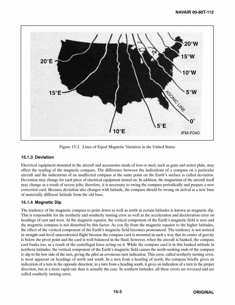
NAVAIR 00-80T-112
ORIGINAL15-3
Figure 15-2. Lines of Equal Magnetic Variation in the United States
15.1.3 Deviation
Electrical equipment mounted in the aircraft and accessories made of iron or steel, such as guns and armor plate, mayaffect the reading of the magnetic compass. The difference between the indications of a compass on a particularaircraft and the indications of an unaffected compass at the same point on the Earth’s surface is called deviation.Deviation may change for each piece of electrical equipment turned on. In addition, the magnetism of the aircraft itselfmay change as a result of severe jolts; therefore, it is necessary to swing the compass periodically and prepare a newcorrection card. Because deviation also changes with latitude, the compass should be swung on arrival at a new baseof materially different latitude from the old base.
15.1.4 Magnetic Dip
The tendency of the magnetic compass to point down as well as north in certain latitudes is known as magnetic dip.This is responsible for the northerly and southerly turning error as well as the acceleration and deceleration error onheadings of east and west. At the magnetic equator, the vertical component of the Earth’s magnetic field is zero andthe magnetic compass is not disturbed by this factor. As you fly from the magnetic equator to the higher latitudes,the effect of the vertical component of the Earth’s magnetic field becomes pronounced. The tendency is not noticedin straight-and-level unaccelerated flight because the compass card is mounted in such a way that its center of gravityis below the pivot point and the card is well balanced in the fluid; however, when the aircraft is banked, the compasscard banks too, as a result of the centrifugal force acting on it. While the compass card is in this banked attitude innorthern latitudes, the vertical component of the Earth’s magnetic field causes the north-seeking ends of the compassto dip to the low side of the turn, giving the pilot an erroneous turn indication. This error, called northerly turning error,is most apparent on headings of north and south. In a turn from a heading of north, the compass briefly gives anindication of a turn in the opposite direction; in a turn from a heading south, it gives an indication of a turn in the properdirection, but at a more rapid rate than is actually the case. In southern latitudes, all these errors are reversed and arecalled southerly turning error.

NAVAIR 00-80T-112
ORIGINAL 15-4
15.1.5 Acceleration Error
Acceleration error is also due to the action of the vertical component of the Earth’s magnetic field. Because of itspendulous-type mounting, the compass card is tilted during changes of speed. This deflection of the card from thehorizontal results in an error that is most apparent on headings of east and west. When the aircraft is accelerating orclimbing on either of these headings, the error is in the form of an indication of a turn to the north; when the aircraftis decelerating or descending, the error is in the form of an indication of a turn to the south. Acceleration error isconstantly present during climb and descent.
15.1.6 Oscillation Error
This error is due to the erratic swinging of the compass card, probably the result of rough air or rough pilot technique.The fluid serves to reduce this oscillation. When the errors and characteristics of the magnetic compass are thoroughlyunderstood, it offers a reliable means of determining the direction in which the aircraft is headed. When reading thecompass to determine direction, make certain the aircraft is as steady as possible; is not in a turn, climb, or dive; andis flying at a constant airspeed.
15.2 AIRSPEED INDICATOR
An airspeed indicator is a presentation of the forward velocity in knots of the aircraft through the surrounding airmass.Components within the instrument case react to the difference between ram and static pressure inputs, causing amechanically linked pointer to indicate the airspeed on a graduated scale. As the ram/static pressure differentialchanges, the pointer indicates a change in airspeed. Depending upon the type instrument, the airspeed depicted maybe either in terms of indicated, true, or displayed as a Mach number (Figure 15-3).
15.3 VERTICAL SPEED INDICATOR (VSI/VVI)
The Vertical Speed Indicator (VSI) or Vertical Velocity Indicator (VVI) (Figure 15-4) measures change of aircraftaltitude in feet per minute (fpm). It indicates the rate of climb or descent by measuring the rate of change inatmospheric pressure. This information is valuable in maintaining specific rates of descent during instrumentapproaches or for maintaining and correcting to a desired altitude.
15.3.1 VSI Error
Vertical speed indicators are subject to two types of error: lag and reversal. After entering or completing an altitudechange, approximately 6 seconds is required for the pressure differential within the instrument itself to equalize. Thistime delay is an inherent error called lag. The vertical speed indicator is also subject to reversal error. This error iscaused by inducing false static pressure in the static system and normally occurs during sudden or abrupt pitchchanges. The reversal error is not synonymous with lag error; however, both may occur simultaneously. Themagnitude of this error varies with the aircraft and the abruptness of pitch changes. The reversal error can beminimized by making small and/or smooth pitch changes.
15.3.2 Dial Calibration
The vertical speed indicator uses a single pointer to indicate rate of altitude change on a fixed circular scale. The scaleis calibrated in 1,000-foot increments. Between 0 and 1, the scale is graduated in 100-foot increments with a0.5 (500-foot) reference for ease of interpretation. The 100-foot increments are beneficial in maintaining a glideslopeand to indicate trends from level flight. Beyond the 1,000 fpm indications, the scale markings vary; some aregraduated in 200-foot increments and others use 500-foot increments. The pointer will not indicate rates of altitudechange in excess of 6,000 fpm.
15.4 TURN AND SLIP INDICATOR
Cockpit instrumentation includes a rate of turn indicator and a slip indicator. Though these are usually integrated inone instrument, they will be discussed separately.

NAVAIR 00-80T-112
ORIGINAL15-5
Figure 15-3. Airspeed Indicators

NAVAIR 00-80T-112
ORIGINAL 15-6
Figure 15-4. Vertical Speed Indicator
15.4.1 Turn Indicator (Needle)
The turn indicator is a vertical needle pointer or, in some aircraft, a miniaturized horizontal sliding bar on the attitudeindicator. A gyroscope is used in its operation. Though some turn indicators still use vacuum-driven gyros, most arenow electrically powered.
The primary function of the turn indicator is to measure the rate at which the aircraft is turning. A secondary functionis to provide an indication of bank as a backup for the attitude indicator.
The needle on the turn indicator is designed to deflect, in the direction the aircraft is turning, one needle width toindicate a turn at the rate of 360° every 2 or 4 minutes. A single needle width deflection on a 2-minute turn needleindicates the aircraft is turning 3° per second. A single needle width deflection on a 4-minute turn needle indicatesthe aircraft is turning 1-1/2° per second.
15.4.2 Slip Indicator (Ball)
The slip indicator, called the ball, is a simple inclinometer. It consists of a marble in a slightly curved clear tubecontaining a liquid. The ball indicates the relationship between the angle of bank and the rate of turn. The forces actingon the ball are gravity and centrifugal force. During a coordinated turn, these forces are in balance and the ball willremain centered (Figure 15-5). When the forces acting on the ball become unbalanced, the ball moves away fromcenter, indicating uncoordinated flight — a skid or slip (Figure 15-6). In a skid, the rate of turn is too large for theangle of bank, and the excessive centrifugal force causes the ball to move to the outside of the turn. Correcting tocoordinated flight requires increasing the angle of bank or decreasing the rate of turn using less rudder or acombination of both. In a slip, the rate of turn is too slow for the angle of bank, and the lack of centrifugal force causesthe ball to move to the inside of the turn. Correcting to coordinated flight requires decreasing the angle of bank orincreasing the rate of turn using more rudder or a combination of both.

NAVAIR 00-80T-112
ORIGINAL15-7
Figure 15-5. Coordinated Single Needle Width Turn Indicator
Figure 15-6. Unbalanced Flight

NAVAIR 00-80T-112
ORIGINAL 15-8
15.5 ANGLE OF ATTACK INDICATOR
Angle of attack is the angle between the mean aerodynamic chord of the wing of a moving aircraft and the relativewind. The angle of attack instrument is a visual indication of aircraft performance. If the angle of attack is used toset the aircraft up for a phase of flight (e.g., maximum range cruise, best rate of climb, optimum landing speed), manyairspeed calculations can be saved. Optimum angle of attack for any phase of flight does not vary with gross weight,bank angle, or density altitude (as does airspeed).
Angle of attack is measured by a sensor on the outside of the aircraft. The sensor aligns itself with the relative windand transmits an electric signal to the cockpit instrument (Figure 15-7), which is a pointer needle against a fixed dial.The instrument displays the angle of attack in numerical units, degrees, or symbols.
15.6 HOVER INDICATOR
The hover indicator (Figure 15-8) operates on information provided from a Doppler radar unit. The Doppler radaremploys continuous wave Doppler radar to measure automatically, continuously, and accurately horizontal andvertical components of the helicopter velocity. Output of the Doppler radar is fed to the hover indicator and isdisplayed as deflection of horizontal and vertical bars as well as a vertical pointer. To indicate fore and aft flight, thehorizontal bar will move opposite to the direction of flight; to indicate drift, the vertical bar will move in a directionopposite to the direction of drift; therefore, the pilot flies toward the bars for correction to a hover. The vertical pointerindicates vertical velocity in either direction and is centered in level flight. The hover indicator provides informationin terms of Groundspeed (GS), drift, and rate of climb or descent. It is used by HS/HC aircraft for instrument takeoffsand to determine zero groundspeed for rescue or Antisubmarine Warfare (ASW) sonar operations.
15.7 CLOCK
A mechanical clock is installed in the instrument presentation, and hours, minutes, and seconds can be read from thedial. Some aircraft are equipped with clocks that have an elapsed time counter feature.
15.8 OUTSIDE AIR TEMPERATURE GAUGE
Outside Air Temperature (OAT) (free air temperature) is indicated in the cockpit of many aircraft. The temperatureof the airmass surrounding the aircraft is shown in either degrees Celsius (°C) or Fahrenheit (°F). Regardless of thescale used, a conversion table will frequently be necessary as temperatures aloft are given in °C and surfacetemperatures are given in °F. This information is useful for, but not limited to, determining true airspeed, true altitude,power required, and power available.

NAVAIR 00-80T-112
ORIGINAL15-9/(15-10 blank)
Figure 15-7. Angle of Attack Indicator
Figure 15-8. Hover Indicator

NAVAIR 00-80T-112
ORIGINAL15-1/(15-2 blank)

NAVAIR 00-80T-112
ORIGINAL16-1
CHAPTER 16
Position Instruments
16.1 ALTIMETERS
An altimeter is a flight instrument that measures the height of the aircraft above a given reference and displays it ona calibrated dial (Figures 16-1 and 16-2). The reference may either be barometric (pressure altimeters) or absolute(radio/radar altimeters).
16.1.1 Pressure Altimeter
Atmospheric pressure decreases with altitude, causing the pressure altimeter (which is a simple barometer, measuringthe weight of the air above it) to indicate altitude (in feet) above the preset reference (altimeter setting).
16.1.1.1 The Altimeter Setting
The altimeter setting is a correction for nonstandard surface pressure only. Atmospheric pressure is measured at eachground station and the value obtained is corrected to sea level according to the surveyed field elevation. The altimetersetting, then, is a computed sea level pressure and should be considered valid only in close proximity to the stationand the surface. It does not reflect nonstandard temperatures (Figure 16-3) nor distortion of atmospheric pressure athigher altitudes; however, except for terrain clearance, the pilot should disregard nonstandard atmospheric effect forair traffic control purposes. All pressure altimeters within close proximity of one another react to these effects in thesame way; thus, normal vertical separation is provided.
During instrument flight below the transition level (18,000 feet in Continental United States [CONUS]), theimportance of obtaining the latest altimeter setting cannot be overemphasized, particularly when flying from an areaof high pressure into a low-pressure area. Refer to Figure 16-4. Above the transition altitude (18,000 feet in CONUS),pressure altitude is used because it is not as important to maintain true altitude as it is indicated altitude. (Midaircollision is a more serious problem than terrain clearance.) Therefore, for high-altitude flights, the altimeter shall beset at 29.92 inches of mercury climbing through 18,000 feet Mean Sea Level (MSL). The current local altimetersetting shall be set prior to descent through the lowest usable Flight Level (FL) as defined in the current FlightInformation Publications (FLIP), Section II.
Altimeters not equipped with mechanical stops near the barometric scalelimits can inadvertently be set with a 10,000-foot error; therefore, whensetting the altimeter, ensure the 10,000-foot pointer is reading correctly.

NAVAIR 00-80T-112
ORIGINAL 16-2
Figure 16-1. Three-Pointer Altimeter
1. BAROMETRIC SCALE2. BAROMETRIC PRESSURE SET KNOB3. 10,000-FOOT COUNTER AND LOW
ALTITUDE WARNING SYMBOL4. 1,000-FOOT COUNTER5. 100-FOOT COUNTER
INDICATED ALTITUDE IS 3,200 FEET
12
3
4
5
Figure 16-2. Altimeter

NAVAIR 00-80T-112
ORIGINAL16-3
Figure 16-3. Effect of Temperature on Altitude
Figure 16-4. Inherent Altimeter Error Due to Pressure Changes

NAVAIR 00-80T-112
ORIGINAL 16-4
16.1.1.2 Setting the Pressure Altimeter
The barometric scale located on the face of the altimeter is calibrated in inches of mercury and is used to set a referenceplane into the instrument. Setting the barometric scale to the altimeter setting causes the altimeter to read indicatedaltitude. If the altimeter setting is given in millibars, an appropriate conversion table must be used.
Each 0.01 change on the barometric scale is equivalent to 10 feet of indicated altitude.
The altimeter must be checked and set prior to each flight. This is accomplished thusly:
1. Dial the current altimeter setting into the barometric scale.
2. Note the difference between the indicated altitude and the known field elevation.
3. If the difference is greater than 75 feet, the altimeter is not acceptable for Instrument Flight Rules (IFR) flight.
NoteIFR flight may be conducted if an aircraft has but one usable pressurealtimeter.
16.1.1.3 Types of Altitude
(Figure 16-5.)
16.1.2 Radio/Radar Altimeters
Basically, both the radio and radar altimeters (Figure 16-6) measure altitude electronically by determining how longit takes for a transmitted signal to be reflected back to a receiver antenna. Both types are similar in principle ofoperation and cockpit presentation and measure absolute altitude. Radio/radar altimeters are FM/CW (frequencymodulation/continuous wave) type, and radar altimeters are of the pulse type. Both indicate terrain clearance withincrements that vary from small scale at low levels through larger scales at higher levels. Pilots should refer to theappropriate NATOPS flight manual for the system used in their type aircraft.
16.2 RANGE INDICATOR
The range indicator (Figure 16-7), the Distance Measuring Equipment (DME) readout, displays slant range distancefrom the aircraft to a selected ground station in nautical miles. The presentation may be separate or integrated witha bearing instrument. The aircraft DME transmitter sends an interrogating pulse, which triggers a ground stationresponse pulse. The distance measuring equipment of the aircraft measures round-trip time and converts it to a displayrepresenting nautical mileage on the range indicator. The interrogation/reply cycle is continuous, and the indicatorconstantly shows slant range. When the aircraft is overhead the ground station, altitude is shown in nautical miles.DME should be considered unusable unless it tests within one-half nautical mile (nm) or 3 percent of the distanceto the station, whichever is greater. The appearance of the warning bar/flag signifies an unusable or unreliable signaland value.

NAVAIR 00-80T-112
ORIGINAL16-5
TYPES OF ALTITUDE
Altitude The vertical distance of a level, a point, or an object considered as a point,measured from a given surface.
Absolute Altitude The altitude above the terrain directly below the aircraft. (QFE)
Pressure Altitude The altitude above the standard datum plane. This standard datum plane iswhere the air pressure is 29.92 inches of mercury (corrected to +15 °C). (QNE)
Density Altitude Pressure altitude corrected for temperature. Pressure and density altitudes arethe same when conditions are standard (refer to standard atmosphere table).As the temperature rises above standard, the density of the air decreases,hence an increase in density altitude.
Indicated Altitude Altitude displayed on the altimeter.
Calibrated Altitude Indicated altitude corrected for installation error. If an altimeter correction cardis available, this definition may include scale error.
True Altitude Calibrated altitude corrected for nonstandard atmospheric conditions. Actualheight above mean sea level. (QNH)
Flight Level A surface of constant atmospheric pressure related to the standard datumplane. In practice, a calibrated altitude maintained with a reference of 29.92inches of mercury on the barometric scale. (QNE)
Figure 16-5. Types of Altitude

NAVAIR 00-80T-112
ORIGINAL 16-6
16.3 BEARING INDICATORS
Current typical navigational bearing displays are discussed in the following paragraph.
16.3.1 Radio Magnetic Indicator (RMI)
The RMI displays aircraft heading with navigational bearing data. It consists of a rotating compass card and twobearing pointers. The compass card is actuated by the aircraft compass system so that it continually displays aircraftmagnetic heading. The aircraft current magnetic heading is displayed on the compass card beneath the top index(Figure 16-8).
The bearing pointers display Automatic Direction Finder (ADF), VOR, or Tactical Air Navigation (TACAN)magnetic bearings to the selected navigational station. Radial position is displayed under the tail of the bearingpointers.
NoteBearing pointers do not function in relation to ILS signals.
Unlike the ADF pointer, the VOR and TACAN bearing pointers do not “point” to an area of maximum signalstrength. VOR and TACAN navigation receivers electronically measure the magnetic course/bearing for displayby the bearing pointers; therefore, if there is a malfunction in the compass system or compass card, the ADF bearingpointer will continue to point to the station, but displays relative bearing only. In the same compass failure situation,the VOR or TACAN bearing pointers do not point to the station; however, they may still indicate proper magneticbearings.
When a compass malfunction is known or suspected to exist, the VOR andTACAN radial displays must be considered unreliable until verified byother means.
When navigating with TACAN, distance from the ground station is displayed on a range indicator (DME)(Figure 16-7).
16.3.2 Bearing-Distance-Heading Indicator (BDHI)
The BDHI displays aircraft heading with navigational bearing data and range information. Except for the rangeindicator, the BDHI is similar in appearance and function to the RMI described in paragraph 16.3.1.
The BDHI consists of a rotating compass card, two bearing pointers, a range indicator, and a range warning flag(Figure 16-8). Some BDHIs also have a heading marker, a heading set knob, and a power warning flag.
The compass card is activated by the aircraft master compass system, and it continually displays aircraft heading. TheBDHI compass card can be operated in various slaved and nonslaved (DG) modes.
The heading marker, if incorporated, may be positioned on the compass card by use of the heading set knob. Oncepositioned, the marker remains fixed relative to the compass card. When the aircraft is on the selected heading, theheading marker is aligned beneath the top index.
Bearing pointer and range information function identically as described under range indicator and Radio MagneticIndicator (RMI) (Figure 16-9).
16.3.3 Horizontal Situation Indicator (HSI)
The HSI displays navigation information to the pilot as though the pilot were above the aircraft looking down. It isessentially a combination of a rotating compass card (actuated by the aircraft master compass system), a radiomagnetic indicator, course indicator, and range indicator (Figure 16-10).
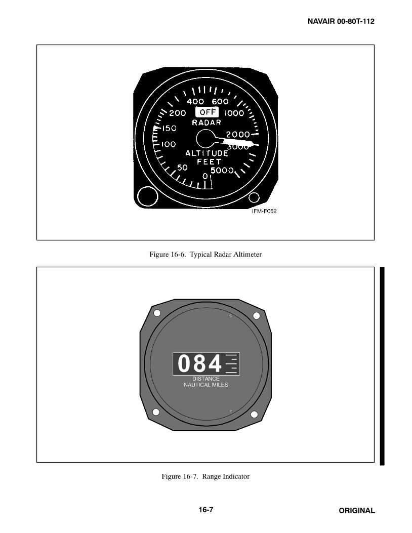
NAVAIR 00-80T-112
ORIGINAL16-7
Figure 16-6. Typical Radar Altimeter
Figure 16-7. Range Indicator

NAVAIR 00-80T-112
ORIGINAL 16-8
Figure 16-8. Bearing-Distance-Heading Indicator (BDHI)
Figure 16-9. Radio Magnetic Indicator (RMI)

NAVAIR 00-80T-112
ORIGINAL16-9
Figure 16-10. Horizontal Situation Indicator (HSI)
The aircraft heading is displayed on the rotating compass card under the top index lubber line.
The bearing pointer indicates the magnetic bearing from the aircraft to the navigation aid selected (VOR, TACAN,or ADF) while the radial position of the aircraft is indicated by the tail of the same bearing pointer. When selectinga course with the course selector knob, a digital display of the course selected will appear in the course selectionwindow, while a graphic relationship between the course selected and the present heading will be shown by the coursearrow. The TO-FROM indicator displays whether the course selected, when intercepted and flown, will direct theaircraft to or from the navigation station selected by the relationship of that station to the fixed aircraft symbol. Thepurpose of the course deviation indicator (bar) shows the relative position of the radial/course desired (selected inthe course selector window) and the fixed aircraft symbol. The series of four dots in the gauge center are scaled torepresent distance off course in degrees. The exact calibration varies between models of aircraft.
The function and use of the heading set and course set knobs are explained fully in applicable NATOPS flight manuals.
When range information is available through DME, the distance to the TACAN station or VOR-DME station isdisplayed in nautical miles.
If the aircraft is not receiving a usable DME signal, the range indicator will be obscured. Loss of bearing informationwill be indicated by an OFF flag appearing near the top of the rotating compass card.
The pilot may select the type of magnetic bearing information desired for display on the bearing pointer.
NoteThe bearing pointer will not function in relation to ILS signals.
When ADF bearing information is displayed, the bearing pointer will point to the area of maximum signal strength;however, when either VOR or TACAN bearing information is displayed, the bearing pointer will not point to the area

NAVAIR 00-80T-112
ORIGINAL 16-10
of maximum strength. VOR and TACAN navigation receivers electronically measure the magnetic course/bearingfor display by the bearing pointer; therefore, if there is a malfunction in the compass system or compass card, andADF bearing information is being displayed, the pointer will continue to point to the navigation aid but displaysrelative bearing only. In the same compass failure situation, when either VOR or TACAN bearing information isdisplayed, the bearing pointer will not point to the navigation aid; however, it may still indicate the proper magneticbearing to that station.
When a compass malfunction is known or suspected to exist, the VOR andTACAN bearing displays must be considered unreliable until verified byother equipment.
16.4 COURSE INDICATOR
The course indicator displays aircraft heading and position relative to a selected VOR/TACAN course. When usedin conjunction with an Instrument Landing System (ILS) localizer and glideslope, the course indicator displays lateral(course) and vertical (glideslope) position relative to a desired instrument approach path (Figure 16-11). Aircraftheading has no relation to the Course Deviation Indicator (CDI). When the CDI is centered, the aircraft is on theselected course, either TO or FROM as indicated, regardless of aircraft heading.
OFF
OFF
10 78
641 32 5
9
1. TO-FROM INDICATOR2. COURSE DEVIATION SCALE3. GLIDESLOPE DEVIATION SCALE4. COURSE SELECTOR WINDOW5. HEADING POINTER6. MARKER BEACON LIGHT7. GLIDESLOPE INDICATOR8. COURSE DEVIATION INDICATOR (CDI)9. COURSE AND GLIDESLOPE WARNING FLAGS
10. COURSE SET KNOB
Figure 16-11. Course Indicator

NAVAIR 00-80T-112
ORIGINAL16-11
16.4.1 VOR/TACAN Display
When the course indicator is used to display VOR or TACAN information, the desired course is set in the courseselector window with the course set knob. The heading pointer, connected to the course set knob and the compasssystem, displays aircraft heading relative to the selected course. When the aircraft heading is the same as the courseselected, the heading pointer indicates 0° of heading deviation at the top of the course indicator. The heading deviationscales at the top and bottom of the course indicator are scaled in 5° increments up to 45°.
Airborne and ground VOR checkpoints and VOR test procedures are listed in FLIP Planning Section II.TACAN/DME checkpoints are normally established on the ground at most airfields. Should a position indicationerror exist in excess of ±4° through use of a ground check or ±6° using an airborne check, the gauge should not beconsidered as acceptable for IFR flight.
The TO-FROM indicator shows whether the course selected, if intercepted and flown, will lead the aircraft to or fromthe selected navigation system. The CDI bar displays the position of the selected course relative to the actual pathof flight of the aircraft. Turning the aircraft until the heading pointer points toward the CDI will correct the aircraftheading toward the selected course. The four dots on the course deviation scale are used in conjunction with the coursedeviation indicator bar to signify a specific number of degrees right or left of the course. The exact calibration variesbetween models of aircraft. A course OFF flag will appear at the top of the gauge whenever the course informationsignal is too weak or unreliable to provide accurate course, or course deviation, information. Should the coursedeviation information presented on the course indicator vary from that course information presented by the bearingpointers on the RMI, BDHI, or HSI (whichever is in use), the bearing pointer should be considered to be moreaccurate.
16.4.2 ILS Display
When the course indicator is used to display ILS signals, the course indicator provides precise ILS localizer courseand glideslope information for a specific approach. The following information pertains to course indicator functionsand display when used on an ILS approach:
1. The TO-FROM indicator is blank.
2. Full-scale deflection on the course indication scale represents approximately 2-1/2° of localizer coursedeviation.
3. The course set knob and the course selected have no effect on CDI display. The CDI displays only whether theaircraft is on course or right or left of course, based upon signal information from a specific selected localizertransmitter; however, even though the course selected has no effect on the CDI, always set the publishedinbound front course of the ILS in the course selector window. This enables you to interpret aircraft positionthrough use of the heading pointer in the same manner described for VOR/TACAN course and positiondetermination.
The Glideslope Indicator (GSI) displays glideslope position in relation to the actual position of the aircraft. Forexample, if the GSI bar is above the center of the gauge, the glideslope is above the aircraft. Each of the four dotsin the vertical row represents approximately 1/4° of deviation from the glideslope.
NoteILS course and glideslope displays are reliable only if their warning (OFF)flags are not in view and the aural ILS identification is being received.
The marker beacon light(s) on the course indicator lights to indicate proximity to a 75-MHz marker beacon (e.g., ILSouter or middle marker). As the aircraft flies through the marker beacon signal pattern, the light flashes in Morse code,indicating the type of beacon being overflown. The marker beacon light is not used in conjunction with VOR orTACAN.

NAVAIR 00-80T-112
ORIGINAL 16-12
16.5 FLIGHT DIRECTOR SYSTEM
Flight Director Systems (FDS) are essentially practical arrangements or groupings of various flight instruments suchas an attitude indicator (director), a position indicator, and a computer. The flight director computer receives positioninformation from the navigation systems and attitude information from the attitude gyro. Depending upon the modesavailable and selected, the computer supplies pitch and/or bank commands to the pitch/bank steering bars of theattitude indicator. The functions of the computer vary with the systems used and the number of inputs provided(Navigation Aids [NAVAIDs], data link, Doppler) and may be processed electronically by the system. Refer to theappropriate NATOPS flight manual for the specific capabilities of the system installed in your aircraft.
16.6 OTHER POSITION INSTRUMENTS
Modern naval aircraft are tending toward more sophisticated instruments for determining aircraft position. Some ofthese systems include radar, inertial, and computerized visual displays. These systems are explained in appropriateNATOPS flight manuals.

NAVAIR 00-80T-112
ORIGINAL75/(76 blank)
PART V
Attitude Instrument Flight
Chapter 17 — Attitude Instrument Flying
Chapter 18 — Instrument Flight Maneuvers
Chapter 19 — Instrument Patterns and Confidence Maneuvers
Chapter 20 — Unusual Attitudes

NAVAIR 00-80T-112
ORIGINAL1/(2 blank)

NAVAIR 00-80T-112
ORIGINAL17-1
CHAPTER 17
Attitude Instrument Flying
17.1 GENERAL
Attitude instrument flying (Figure 17-1), like visual flying, uses reference points to determine the attitude of theaircraft. When flying by visual reference to the Earth’s surface, the attitude of the aircraft is determined by observingthe relationship between the nose and wings of the aircraft and the natural horizon. When flying by reference to flightinstruments, the attitude of the aircraft is determined by observing indications on the instruments. These indicationsgive essentially the same information as obtained by visual reference to the Earth’s surface. The same controltechniques are employed during attitude instrument flying that are used in visual flying. The largest learning factorin attitude instrument flying is correctly interpreting the indications of the various instruments to determine theattitude of the aircraft.
17.2 AIRCRAFT CONTROL
Aircraft control consists of controlling the aircraft about its three axes (pitch, roll, and yaw) and maintaining the power(thrust) at the desired level. Pitch is the movement of the aircraft about its lateral axis. Roll is the movement of theaircraft about its longitudinal axis. Yaw is the movement of the aircraft about its vertical axis. Power control is theadjustment of engine or accessory controls to alter thrust and, therefore, the thrust/drag relationship. When necessary,the appropriate control is applied by reference to the power indicator(s) in the cockpit. Power is not generally affectedby such factors as turbulence, improper trim, or inadvertent aircraft control pressures (Figure 17-2).
Figure 17-1. Attitude Instrument Flying

NAVAIR 00-80T-112
ORIGINAL 17-2
Figure 17-2. Control Axes of an Aircraft
After interpreting the pitch, bank, or yaw attitude from the applicable instruments, control pressures are exerted toattain the desired attitude.
17.2.1 Attitude Control
Proper control of aircraft attitude is the result of maintaining a constant attitude, smoothly changing the attitude adefinite amount, and knowing when and how much to change the attitude. Aircraft attitude control is accomplishedby proper use of the attitude indicator. The attitude indicator provides an immediate, direct, and correspondingindication of any change in aircraft pitch or bank attitude. In addition, by means of the attitude indicator, small pitchor bank changes are easily seen and changes of any magnitude can readily be accomplished.
17.2.1.1 Pitch Control
Pitch changes are accomplished by changing the pitch attitude of the miniature aircraft or fuselage dot definiteamounts in relation to the horizon bar. The fuselage dot is generally referred to as the pipper, and pitch changes arereferred to as pipper widths, or fractions thereof, and/or degrees depending upon the type of attitude indicator(Figure 17-3).
17.2.1.2 Bank Control
Bank changes are accomplished by changing the bank attitude or bank pointer(s) definite amounts in relation to thebank scale. The bank scale is graduated at 0°, 10°, 20°, 30°, 60°, and 90°. This scale is located at the bottom of someattitude director indicators (Figure 17-4).
17.2.1.3 Yaw Control
Yaw changes are made with the rudder pedals. Yaw control in conjunction with bank control is used to maintain theaircraft in balanced flight (centered ball on the turn and slip indicator).

NAVAIR 00-80T-112
ORIGINAL17-3
20° CLIMB 10° DIVE
Figure 17-3. Pitch Attitude Indications
30° LEFT BANK 30° RIGHT BANK
Figure 17-4. Bank Attitude Indications

NAVAIR 00-80T-112
ORIGINAL 17-4
17.3 INSTRUMENT GROUPINGS
17.3.1 Control Instruments
Power and attitude indicators are termed control instruments. A proper combination of pitch, roll, yaw, and powercontrol will achieve the desired aircraft performance (Figure 17-5).
17.3.2 Performance Instruments
The performance of the aircraft is determined by reference to the vertical speed indicator; heading indicator;airspeed/Mach indicator; Angle of Attack (AOA) indicator; clock, turn, and slip indicator (needle and ball indicator);and, in some cases, the altimeter. Although the altimeter is primarily a position instrument, in some maneuvers it canbe used as a cross-check on aircraft performance. These instruments are termed performance instruments and indicatethe aircraft performance, regardless of whether the pilot is referring to the Earth’s horizon, the attitude indicator, orboth, to control the aircraft attitude (Figure 17-5).
17.3.3 Position Instruments
The aircraft position is determined by a third group of instruments termed position instruments. These instrumentsinclude various types of course indicators, range indicators, glideslope indicators, and altimeter and bearing pointers.By knowing the aircraft position, the pilot can determine what control changes are required to achieve desired aircraftperformance (Figure 17-5).
17.3.4 Instrument Scan
During instrument flight, the pilot’s attention must be divided between the control, performance, and positioninstruments. Proper division of attention and the sequence of checking the instruments (scan) varies among pilots andthroughout various phases of flight. There is no one set order for scanning the instruments, as it depends on the typeof maneuver to be executed as to which instruments are of prime importance; however, the pilot should becomefamiliar with the factors to be considered in dividing attention between instruments properly. The pilot should alsoknow the symptoms that enable recognition of correct and incorrect scan technique. These factors and symptoms arediscussed in the following paragraphs.
As an example of how improper scanning occurs, consider the case of a pilot attempting to reduce the airspeed andhold straight-and-level flight. As the power is reduced, the pilot observes the engine performance gauge so closely,in order to make the proper adjustments, that the pilot neglects to observe the additional instruments that wouldindicate a deviation from straight-and-level flight. This failure to maintain a systematic and effective instrument scanis one of the major causes of poorly executed flight maneuvers.
17.3.5 Functions of Instruments — Full Panel Scan
The combination of a particular power setting and aircraft attitude will deliver a specific performance. In simpleterms:
Power + Attitude = Performance.
A thorough understanding of this principle is essential to building an efficient scan pattern. Although the VerticalSpeed Indicator (VSI), altimeter, heading indicator, airspeed indicator, and turn needle ball are referred to as theposition or performance instruments, depending on aircraft maneuver, it should be understood that the specificfunction of these instruments in a full panel scan depends on the maneuver being completed.

NAVAIR 00-80T-112
ORIGINAL17-5
CONTROL AND PERFORMANCE CONCEPT
Procedural Steps:1. Establish an attitude and/or power setting on the control instrument(s) which should result in the desired
performance.
2. Trim until control pressures are neutralized.
3. Crosscheck the performance instruments to determine if the established attitude and/or power setting areproviding the desired performance.
4. Adjust the attitude and power setting on the control instruments if a correction is necessary.
Figure 17-5. Position, Control, and Performance Instrument Groupings

NAVAIR 00-80T-112
ORIGINAL 17-6
For every full panel maneuver, the attitude gyro is the primary reference instrument for both nose and wing attitude;however, the instruments comprising the performance group are used to verify the desired attitude and performanceof an aircraft and to detect any deviation from them. Thus, the performance instruments also function as attitudecross-checks; for example, in straight-and-level flight, the altimeter and VSI function as nose attitude cross-checks,and the heading indicator serves as the wing attitude cross-check (i.e., the altimeter and VSI are checked to verifya constant altitude, and the heading indicator is checked to verify constant heading). The airspeed indicator is the onlyone of the so-called performance instruments that is actually being scanned for performance (desired airspeed) duringstraight-and-level flight (Figure 17-6).
ManeuverBasic Attitude
Instrument
Nose AttitudeCross CheckInstruments
Wing AttitudeCross CheckInstruments
PerformanceInstruments
SupportingInstruments
Straight and level Attitude gyro Altimeter, VSI Heading indicator,Needle ball
Airspeedindicator
Power,Angle of attack
Constant airspeedclimbs and descents
Attitude gyro Airspeedindicator
Heading indicator,Needle ball
Altimeter Power,Angle of attack
Constant rateclimbs and descents
Attitude gyro Airspeedindicator
Heading indicator,Needle ball
Altimeter,Clock, VSI
Power,Angle of attack
Constant angle ofbank turns (level)
Attitude gyro Altimeter, VSI Headingindicator,Airspeedindicator
Needle Ball,Power
Constant rate turns(level)
Attitude gyro Altimeter, VSI Needle ball Headingindicator,Airspeedindicator
Power
Climbing ordescending turns at aconstant rate
Attitude gyro Airspeedindicator
Needle ball Headingindicator, Clock,VSI, Altimeter
Power,Angle of attack
Hovering Attitude gyro Hover indicator Hover indicator,Needle ball
Radar altimeter,Headingindicator;See Note
Power
Note
The inherent lag and relatively large scaling of pressure-sensitive instruments precludes their use asperformance instruments while hovering in close proximity to the surface.
Figure 17-6. Function of Instruments (Full Panel)
17.3.6 Scan Technique
A major factor influencing scan technique is the characteristic manner in which instruments respond to attitude andpower changes. The control instruments provide a direct and immediate indication of attitude and power changes,but indications on the performance instruments lag and must be accepted as an inherent factor. Lag will notappreciably affect the tolerances within which the pilot controls the aircraft; however, at times, a slight, unavoidabledelay in knowing the results of attitude and/or power changes will occur.
When the attitude and power are smoothly controlled, the lag factor is negligible and the indications on theperformance instruments will stabilize or change smoothly. Do not make abrupt control movements in response tothe lagging indications on the performance instruments without first checking the control instruments. Failure to doso leads to erratic aircraft maneuvers, which will cause additional fluctuations and lag in the performance instruments.Frequent scanning of the control instruments assists in maintaining smooth aircraft control.

NAVAIR 00-80T-112
ORIGINAL17-7
The attitude indicator is the instrument that should be used to develop all maneuvering attitudes and should be scannedmost frequently. This is shown by the following description of a normal scan: A pilot glances from the attitudeindicator to a performance instrument; back to the attitude indicator; then a glance at another performance instrument;back to the attitude indicator; and so on.
It is often necessary to compare the indications of one performance instrument against another before knowing whenor how much to change the attitude or power. An effective scan technique may require that the attitude indicator bescanned between glances at the performance instruments being compared (Figure 17-7).
17.3.7 Scan Analysis
An incorrect scan technique may be recognized by analyzing certain symptoms. If the correct attitude and powerindications are not established and maintained, and other instrument indications fluctuate erratically, the pilot isprobably fixating on a single instrument or not scanning the control instruments often enough. This is usuallyaccompanied by lack of precise aircraft control.
Too much attention being devoted to the control instruments, although rarely encountered, is normally caused by apilot’s desire to maintain performance indications within close tolerances. If the pilot has a smooth, positive, andcontinuous control over the indications of the control instruments, but large deviations are observed to occur on theperformance instruments, a more frequent scan of the performance instruments is required.
An incorrect scan can result in the omission of, or insufficient reference to, one or more instruments during thescanning process. For example, during a climb or descent, a pilot may become so engrossed with pitch attitude controlthat he/she fails to observe an error in the aircraft heading. A 4° heading change is not as eye-catching as a 300- to400-fpm change on the vertical speed indicator.
Through deliberate effort and proper habit, the pilot must ensure all the instruments are included in his/her scan.Continuous analysis of a pilot’s scan technique will assist in early recognition and correction of errors or omissionsand will result in improved aircraft control.
17.3.8 Use of Angle of AttackAngle of attack information is most valuable during an instrument approach. In the event of airspeed indicator failure,angle of attack information can be used throughout a flight if equivalent values are known. As with the other flightinstruments, the angle of attack indicator and components should be checked for proper alignment and calibrationand freedom of movement prior to takeoff.
During takeoff, the airspeed indicator may be used to determine acceleration speed, takeoff speed, minimum controlspeed, etc.; however, the angle of attack indicator should be used in conjunction with the attitude indicator to establishthe proper angle of attack for takeoff. Angle of attack information may also be used to varying degrees to establishbest climb angles, maximum endurance, long-range cruise, glides, and other flight maneuvers. The final approachairspeed given in the NATOPS flight manual is based on a given constant angle of attack. Because the angle of attackduring the approach phase of flight remains the same regardless of weight, it is a more direct indication of best finalapproach speed than indicated or Calibrated Airspeed (CAS).
During an approach, the landing configuration and approach angle of attack should be established prior tocommencing the final approach descent. To establish the approach angle of attack, reduce airspeed and maintainaltitude until the desired indications are established on the angle of attack indicator/indexer. The resulting airspeedwill be the best final approach for that weight; thus, the airspeed and angle of attack indicators may be used tosupplement one another.
Control of angle of attack and rate of descent require coordinated power and pitch changes. If the aircraft is abovethe glideslope with the desired angle of attack, the pilot should decrease power to increase rate of descent and adjustthe nose to maintain the desired angle of attack, the pilot should increase power to decrease the rate of descent andadjust the nose to maintain the desired angle of attack.

NAVAIR 00-80T-112
ORIGINAL 17-8
Primary instrument scan should focus on the attitude indicator, with periodicscans to airspeed, heading, altitude, VVI, turn & slip, and engine indications.
Figure 17-7. Instrument Scan Technique

NAVAIR 00-80T-112
ORIGINAL17-9
17.4 AIRCRAFT TRIM
The aircraft is correctly trimmed when it is maintaining a desired attitude with all control pressures neutralized. Byrelieving all control pressures, the pilot will find that it is much easier to hold a given attitude. Also, more attentioncan be devoted to the navigation instruments and additional cockpit duties. Proper trim technique is essential forsmooth and precise aircraft control during all phases of flight.
An aircraft is placed in trim by applying control pressure(s) to establish a desired attitude and then adjusting the trimso that the aircraft will maintain that attitude when the flight controls are released. The aircraft should be trimmedfor coordinated flight by first centering the ball on the turn and slip indicator, followed by trim corrections to theelevator and aileron controls. On multiengine aircraft, where differential power control is possible, balancedpower/thrust will aid in maintaining coordinated flight. Changes in attitude, power, or configuration may require atrim adjustment. Use of trim to change the aircraft attitude will probably lead to erratic aircraft control. Smooth andprecise attitude changes are best attained by a combination of control pressures and trim adjustments (Figure 17-8).
NoteThe preceding concepts of attitude instrument flying apply to helicoptersauthorized for instrument flight; however, power changes are normallymade with collective pitch, and attitude changes with cyclic stick.
Figure 17-8. Trim Technique
NAVAIR 00-80T-112
ORIGINAL 17-10
17.5 INSTRUMENT HOVERING
Many Search and Rescue (SAR) and Antisubmarine Warfare (ASW) helicopters are equipped with Doppler radarhover instruments (as described in paragraph 15.6), which allows the pilots to accomplish a hover without visualreference to the surface. As with all instrument flight, this is a full panel maneuver and must include a scan of all flightinstruments. The primary scan instrument should be the attitude gyro, while the hover indicator should be used asthe nose and wing attitude cross-checks.
The demanding nature of this maneuver, particularly in an uncoupled environment, requires a very rapid scan. Everyeffort should be made to determine a stable hover reference position on the attitude gyro and all hover correctionsshould be made back to this position. The hover indicator is commonly mistaken for the primary scan instrument,but because of the inherent lag of this indicating system, it is better used as a cross-check instrument. For specificflight procedures, consult the applicable aircraft NATOPS manuals.

NAVAIR 00-80T-112
ORIGINAL18-1
CHAPTER 18
Instrument Flight Maneuvers
18.1 APPLICATION
The maneuvers described in this chapter are those most commonly used during instrument flight. Additionalmaneuvers or some modification of these maneuvers may be required for specific unit training requirements. Thedegree of proficiency attained in accomplishing these maneuvers will assist the pilot in adapting to actual instrumentflight.
An instrument flight, regardless of its length or complexity, is a series of connected basic instrument flight maneuvers(Figure 18-1). Failure to consider each portion of the flight as a basic instrument maneuver often leads to erraticaircraft control.
18.1.1 Planning
The information received from the navigational instruments or an air traffic controller should be considered asadvising the pilot what maneuver to perform, when to perform it, or what adjustments, if any, are required. Terminalapproach charts and similar publications should be considered as pictorial presentations of a series of connectedinstrument flight maneuvers. Keeping these considerations in mind and calling upon previous practice, the pilot willfind that he/she is always performing a familiar maneuver. By visualizing the next maneuver, the pilot can plan aheadand know exactly what cross-check and aircraft control techniques to employ at the time of entry into the maneuver.
Figure 18-1. Typical Instrument Flight

NAVAIR 00-80T-112
ORIGINAL 18-2
18.2 INSTRUMENT TAKEOFF (ITO)
18.2.1 Pretakeoff Procedures
The ITO procedures and techniques are an invaluable aid during takeoffs at night, toward and over water or desertedareas, and during periods of reduced visibility. These takeoffs are accomplished by combined use of outside visualreference and the flight instruments. The amount of attention given to each ITO varies with the individual, the typeof aircraft, and existing weather. As the ITO is a composite visual/instrument takeoff, it should not be confused norused interchangeably with hooded takeoffs.
Prior to commencing an instrument flight, the pilot shall check the flight and navigation instruments and the requiredpublications. This check will be made in accordance with the NATOPS flight manual and must include all control,performance, and position instruments. Many airdromes display navigational data on a sign near the end of the runwayfor checking the navigational equipment and altimeter. After this pretakeoff check is complete, select the navigationalaids to be used for the departure and set the navigational instruments and switches as required.
The air traffic control clearance and departure procedures must be thoroughly understood prior to takeoff. Theappropriate instrument approach charts shall be readily available in the event that an instrument approach becomesnecessary immediately after takeoff.
18.2.1.1 ITO Procedures (Fixed Wing)
The ITO for specific aircraft is discussed in the applicable NATOPS flight manual. Use pitot heat and other anti-iceequipment as appropriate. When cleared, align the aircraft with the runway centerline and complete any remainingchecklists. Pay special attention to the heading and attitude indicators for any errors induced by turning while taxiing.When directed, select the assigned departure frequency and monitor Guard frequency during takeoff.
When cleared for takeoff, release the brakes simultaneously to minimize initial directional control difficulties.Directional control immediately following brake release should be accomplished predominantly by outside visualreferences (Figure 18-2). As the takeoff progresses, the pilot’s scan should transition from outside references to theheading, airspeed, angle of attack, and attitude indicators. The rate of transition is directly proportional to the rate atwhich the outside reference deteriorates. It is essential that the pilot establish his/her instrument scan prior to losingall visual reference.
The takeoff attitude will normally be established on the attitude indicator at rotation or just prior to reaching takeoffairspeeds. Pilots should know the takeoff attitude indicator picture required for their aircraft. The takeoff attitudeshould be maintained as the aircraft leaves the ground. If available, the angle of attack indicator should be used tocross-check the attitude indicator for optimum takeoff performance. Check the vertical speed indicator and altimeterfor positive climb indications and comply with the applicable NATOPS flight manual for specific aircraft beforeretracting the gear and wing flaps. While the gear and flaps are being retracted, maintain or adjust the pitch attitudeas necessary to ensure the desired climb.
NoteSome attitude indicators are susceptible to precession errors due to aircraftacceleration. This phenomenon causes the horizon bar to lower slightly andappears as an increased pitch attitude. To avoid lowering the noseprematurely, the pilot must cross-check the vertical speed, angle of attackindicator, and altimeter throughout this phase of flight to ensure properclimb performance.
After the gear and flaps are retracted, the pitch attitude should be controlled to provide an increase in airspeed whileclimbing until the normal climb schedule is reached.

NAVAIR 00-80T-112
ORIGINAL18-3
Figure 18-2. Instrument Takeoff
18.2.1.2 Rotary Wing ITO
If visibility will permit, establish a normal hover to perform the safety checks of flight controls, engines, andautomatic stabilization equipment. When a normal hover is not possible, the helicopter may be flown off the deckand into a normal climb without any outside reference. In the event of full instrument takeoff when outside visualreference cannot be maintained at hover altitudes, use the hover indicator, when available, to determine a positiverate of climb, indicate sideward drift, and indicate fore and aft groundspeed prior to reliable airspeed indications.Heading control may be maintained with the yaw stabilization channel of the automatic stabilization equipment.Steadily increase collective as the helicopter lifts off. Maintain level attitude on the attitude indicator.
NoteTo maintain a stable hover with no sideward drift, it may be necessary insome helicopters to hover with a slight wing-down attitude.
As altitude increases through approximately 15 feet, use the radar altimeter and lower the nose to approximately 5°below hover attitude. (See applicable NATOPS flight manuals for variations.) Simultaneously increase the collectiveto the best climb setting and adjust the nose attitude to accelerate to the recommended climbing airspeed.
NoteWhen passing through translational lift, the nose attitude may requirereadjustment to maintain the attitude desired.
18.2.1.3 Night (Instrument) Catapult Launch
The night (instrument) launch from a carrier deck differs considerably from an ITO in that it is a demanding maneuverperformed entirely on instruments. Prior to taxiing from a deck spot to the catapult, it is absolutely essential that allaircraft systems communication and navigation equipment be checked for proper operation and set on the desired

NAVAIR 00-80T-112
ORIGINAL 18-4
frequency. At night, the exterior lights should be set up in accordance with the CV NATOPS manual. The aircraftshould also be configured (flaps set) for catapult launch in accordance with the applicable NATOPS flight manualfor the launch gross weight and Wind-Over-Deck (WOD).
En route to the catapult, performance and position instruments should be checked for proper operation (turn needle,Horizontal Situation Indicator [HSI], wet compass, Tactical Air Navigation [TACAN]). While being spotted on thecatapult, pilot attention must necessarily be outside the cockpit; however, once the signal to “TAKE TENSION” isgiven, the pilot is from that time on instruments. The desired departure course should be checked and set in, theBearing-Distance-Heading Indicator (BDHI) heading cross-checked with the Base Recovery Course (BRC), and theattitude instrument(s) should be checked for proper operation and alignment. When satisfied that you and the aircraftare ready for launch, the appropriate signal is given.
The primary instrument during the catapult stroke is the attitude gyro. At the end of the catapult stroke, the desiredclimb attitude is established on the attitude indicator and then cross-checked with the vertical speed indicator andaltimeter for a positive climb indication while maintaining launch heading. Once comfortably established in a climb,the gear can be raised and an airborne radio transmission can be made. After accelerating to the airspeed/altitudeprescribed for the type aircraft, a transition to a clean/cruise configuration can be effected. During the transition fromlaunch to cruise configuration, the angle of attack should be checked to ensure optimum attitude performance is beingmaintained. Normal Case II or III departure procedures should be complied with during climb to en route operatingaltitude.
The standby attitude gyro should be illuminated with a flashlight duringcatapult launch. Failure to do so could result in the loss of attitudeinformation in the event of a generator failure and cause subsequent loss ofthe aircraft.
Radio frequency changes should not be attempted until above 2,500 feet unless level flight for an extended periodof time is planned.
18.2.1.4 Rotary Wing Night (Instrument) Shipboard Takeoffs
During night shipboard operations, instrument takeoffs should be utilized any time weather is less than 1,000 feetceiling and 3 miles visibility or there is no visible horizon. When flight deck conditions permit, takeoffs should bemade utilizing available flight deck during transition to forward flight. Both pilots must closely monitor initial rateof climb utilizing both radar altimeter and Vertical Speed Indicator (VSI). Descent or lack of climb during takeoffrequires immediate corrective action. Heading, radio frequency, and control changes should not be initiated prior to200 feet.
18.3 STRAIGHT-AND-LEVEL FLIGHT
Straight-and-level unaccelerated flight consists of maintaining a constant altitude, heading, and airspeed. Bank isused with yaw to maintain balanced flight and to maintain or adjust the heading. Pitch and power control should notbe considered independently because coordinated control of both is necessary to maintain or adjust altitude orairspeed.
18.3.1 Maintaining a Desired Altitude
Maintaining a desired altitude requires the ability to maintain a specific pitch attitude and, when necessary, tosmoothly and precisely adjust this attitude. This ability is developed through proper use of the attitude indicator andis simplified by good trim techniques. The pilot must recognize and understand the application of these requirements.The pilot should also be thoroughly familiar with the procedures in attitude instrument flying.

NAVAIR 00-80T-112
ORIGINAL18-5
After leveling off at cruise airspeed, adjust the pitch trim knob on the attitude indicator so that the miniature aircraftis aligned with the horizon bar. This will aid in observing small pitch changes. Subsequent readjustments may berequired because of changes in aircraft gross weight and cruise airspeeds (Figure 18-3).
The first indication of altitude deviation normally appears on the vertical speed indicator. By observing the initial rateof movement, the pilot may estimate the amount of pitch change required on the attitude indicator and prevent largealtitude deviations. If the estimated pitch change was correct, the vertical speed will return to zero with a negligiblechange of indicated altitude on the altimeter.
The small pitch corrections required to maintain a desired altitude are made in fractions of pippers or in degrees. Thepilot should become familiar with the vertical speed changes that result when specific pitch adjustments are madeat various airspeeds and configurations; thus, the pilot can determine what nose attitude adjustment is required toproduce the desired rate of correction when an altitude deviation is observed.
When the pilot makes these pitch adjustments, the altimeter and vertical speed indications will lag behind changesof pitch attitude on the attitude indicator. This lag should be recognized and accepted as an inherent error in thedifferential pressure instruments. The error is even more pronounced at supersonic airspeeds. Because of this error,the pilot must maintain the adjusted pitch attitude on the attitude indicator while waiting for changes on the altimeterand vertical speed to occur. The pilot must not make a snap decision that the adjusted pitch change is ineffective andbe lured into overcontrolling the nose attitude.
With experience, the pilot can usually estimate the suitability of a pitch adjustment by noting the initial rate ofmovement of the vertical speed indicator. For example, assume a pitch adjustment has been made that is expectedto result in a 200- to 300-feet-per-minute rate of climb. If the initial rate of movement on the vertical speed indicatoris rapid and obviously will stabilize at a rate greater than desired, the pitch change was too large. Readjust the pitchattitude rather than wait for a stabilized indication on the vertical speed indicator.
Figure 18-3. Adjusting the Attitude Indicator

NAVAIR 00-80T-112
ORIGINAL 18-6
When a deviation from the desired altitude occurs, exercise good judgment in determining a rate of correction. Thecorrection must not be too large and cause the aircraft to overshoot the desired altitude, nor should it be so small thatit is unnecessarily prolonged. As a guide, the pitch attitude change on the attitude indicator should produce a rate ofvertical speed approximately twice the size of the altitude deviation. Usually pitch changes are made in fractions (1/4,1/2, 3/4, etc.) of pippers or degrees. For example, if the aircraft is 100 feet off the desired altitude, a200-feet-per-minute rate of correction would be a suitable amount. By knowing the present rate of climb or descentand the results to be expected from a pitch change, the pilot can closely estimate how much to change the pitch attitude.Initially, this pitch change is an estimated amount; therefore, the adjusted pitch attitude must be held constant untilthe rate of correction is observed on the vertical speed indicator. If it differs from that desired, further adjustment ofthe nose attitude is required (Figure 18-4).
When approaching the desired altitude, determine a lead point on the altimeter for initiating a level-off pitch attitudechange. A suitable lead point prevents overshooting and permits a smooth transition to level flight. The amount oflead required varies with pilot technique and rate of correction. As a guide, the lead point on the altimeter should beapproximately 10 percent of the vertical speed. For example, if the rate of correction to the desired altitude is 300 feetper minute, initiate the level-off approximately 30 feet before reaching the desired altitude (Figure 18-5).
Devoting too much attention to the vertical speed indicator can lead to “chasing” its indications and result in erraticnose attitude control; although the vertical speed indicator is an important performance instrument, limitation suchas oscillation in rough air, lag, etc. should be thoroughly understood to prevent overcontrolling the pitch attitude. Forthis reason, the pilot must recognize and understand that sufficient reference to the attitude indicator is necessary toensure smooth and precise pitch adjustments for effective altitude control.
18.3.1.1 Maintaining a Desired Heading
Maintaining a desired heading is accomplished by maintaining a wings-level attitude in balanced flight. By observingthe heading indicator, the pilot determines if the desired heading is being maintained. Heading deviations are notnormally as eye-catching as altitude deviations; therefore, be aware of this characteristic and develop a habit ofcross-checking the heading indicator frequently to prevent significant heading deviations.
When a deviation from the desired heading occurs, refer to the attitude indicator and smoothly establish a definiteangle of bank that will produce a suitable rate of return. As a guide, the angle-of-bank change on the attitude indicatorshould equal the heading deviation in degrees. For example, if the heading deviation is 10°, then 10° of bank on theattitude indicator would produce a suitable rate of correction (Figure 18-6). This guide is particularly helpful duringinstrument approaches at relatively slow airspeeds. At higher true airspeeds, a larger angle of bank may be requiredto prevent a prolonged correction. Proper pitch and bank attitude control requires the pilot to recognize the effectsof gyroscopic precession on attitude indicators. This precession is most noticeable following a turn or change ofairspeed. As a result, small altitude and heading deviations may occur when a wings-level attitude is established onthe attitude indicator following these maneuvers; therefore, the pilot may have to establish temporarily a pitch or bankattitude other than that ordinarily expected. For example, to maintain straight-and-level flight on the performanceinstruments after completing a normal turn, the attitude indicator may depict a slight turn, climb or descent, or acombination of both. The attitude indicator will gradually resume its normal indications as the erection mechanismautomatically corrects these errors. When these errors occur, apply the basic cross-check procedure (Figure 18-7).
18.3.1.2 Establishing and Maintaining Airspeed
Establishing or maintaining an airspeed is accomplished by referring to the airspeed and/or Mach indicator andadjusting the power and/or aircraft attitude. A knowledge of the approximate power required to establish a desiredairspeed will aid in making power adjustments. After the approximate power setting is established, a cross-check ofthe airspeed indicator will indicate if subsequent power adjustments are required. The pilot should make it a pointto learn and remember the approximate power settings and attitudes for the aircraft at various airspeeds andconfigurations used throughout a normal mission.

NAVAIR 00-80T-112
ORIGINAL18-7
WITH PRACTICE YOUCAN CLOSELY ESTIMATETHE AMOUNT OF PITCHCHANGE REQUIRED TORETURN TO THEDESIRED ALTITUDE.
YOU SEE THAT THE AIRCRAFT IS100 FEET BELOW THE DESIREDALTITUDE AND DECIDE THAT YOUSHOULD CLIMB BACK AT 200 FPM.
YOU NOTE THAT YOUARE DESCENDING AT300 FPM.
Figure 18-4. Correcting to the Desired Altitude
LEAD THEALTITUDE30 FEET.
Figure 18-5. Leading the Level-Off

NAVAIR 00-80T-112
ORIGINAL 18-8
Figure 18-6. For Turns 30° or Less, Limit the Angle of Bank to the Number of Degrees to be Turned
When an airspeed deviation is observed, a power or pitch adjustment, or a combination of both, may be required tocorrect back to the desired airspeed; however, check the altimeter and vertical speed before making a poweradjustment. If below the desired altitude with a higher-than-desired airspeed, a small pitch adjustment may regainboth the desired airspeed and altitude. Conversely, when maintaining the desired airspeed, a pitch adjustment willinduce the need for a power adjustment.
Changes of airspeed in straight-and-level flight are accomplished by adjusting the power and/or drag devices. Toincrease the airspeed, advance the power beyond the setting required to maintain the new desired airspeed. As theairspeed increases, the aircraft gains lift and will have a tendency to climb. Adjust the nose attitude as required tomaintain altitude. When the airspeed approaches the desired indication, reduce the power to an estimated setting thatwill maintain the new airspeed. To reduce the airspeed, reduce the power below the setting estimated for maintainingthe new desired airspeed. As the airspeed decreases, the aircraft loses lift and will have a tendency to descend. Adjustthe nose attitude as required to maintain altitude. When the airspeed approaches the desired indication, advance thepower to an estimated setting that will maintain the new airspeed (Figure 18-8). If available, drag devices may be usedfor relatively large or rapid airspeed reductions. If used, it is normally best to reduce the power to the estimated settingthat will maintain altitude at the new airspeed and then extend the drag device(s). Extending or retracting the dragdevices may induce a pitch change. To overcome this tendency, note the nose attitude on the attitude indicator justbefore operating the drag devices and then maintain that attitude constant as they are extended or retracted. Whenapproaching the new airspeed, retract the drag devices and adjust power if required.
18.3.2 Level Turns
Many of the pitch, bank, and power principles discussed in maintaining straight-and-level flight apply whileperforming level turns. Performing a level turn requires an understanding of several factors: how to enter the turn;how to maintain bank, altitude, and airspeed during the turn; and how to recover from the turn.

NAVAIR 00-80T-112
ORIGINAL18-9
IMMEDIATELYAFTER TURNING
It may be necessaryto maintain thisindication due toprecession.
ATTITUDEINDICATION
PRIOR TO TURN
Figure 18-7. Effects of Precession on Attitude Indicators

NAVAIR 00-80T-112
ORIGINAL 18-10
Figure 18-8. Use of Power
18.3.2.1 Bank Control
Prior to entering a turn, the pilot should decide upon an angle of bank to be used. Factors to consider are True Airspeed(TAS) and the desired rate of turn. A slow turn rate may unnecessarily prolong the turn, whereas a high rate of turnmay cause overshooting of the heading and difficulty with nose attitude control. As a guide for small turns (30° orless), the angle of bank used should approximate the number of degrees to be turned. For turns of more than 30°, abank angle of 30° is normally used. High true airspeed and/or flight manual procedures for the equipment being usedmay require other angles of bank.
To enter a turn, the pilot should refer to the attitude indicator while applying smooth and coordinated control pressuresto establish the desired angle of bank. Bank control should then be maintained throughout the turn by reference to theattitude indicator. Cross-check the heading indicator and/or turn needle to determine if the angle of bank is satisfactory.Trim may be helpful during prolonged turns to assist in aircraft control. To enter a turn, the pilot should refer to theattitude indicator while applying smooth and coordinated control pressures to establish the desired angle of bank. Bankcontrol should then be maintained throughout the turn by reference to the attitude indicator. Cross-check the headingindicator and/or turn needle to determine if the angle of bank is satisfactory. Trim may be helpful during prolonged turnsto assist in aircraft control.
To roll out of a turn on a desired heading, a lead point must be used. The amount of lead required depends upon theamount of bank used for the turn, the rate the aircraft is turning, and the rate at which the pilot rolls out. As a guide,a lead point on the heading indicator equal to approximately one-third the angle of bank may be used. With experienceand practice, a consistent rate of rollout can be developed. A lead point can then accurately be estimated for anycombination of angle of bank and rate of turn. Make a note of the rate of movement of the heading indicator during theturn. Estimate the lead required by comparing this rate of movement with angle of bank being used and the rate ofrollout (Figure 18-9).

NAVAIR 00-80T-112
ORIGINAL18-11
LEAD ROLLOUT HEADINGBY 1/3 ANGLE OF BANK (8°)
Figure 18-9. Leading the Rollout
18.3.2.2 Altitude Control
The techniques for maintaining a constant altitude during a turn are similar to those used in maintainingstraight-and-level flight. During the initial part of the roll-in, hold the same pitch attitude as was used to maintainaltitude with the wings level. As the bank is increased, the pilot should anticipate a tendency for the aircraft to losealtitude because of the loss of vertical lift. Adjust the nose attitude as necessary by reference to the pipper of theminiature aircraft relative to the horizon bar. After the turn is established, small pitch adjustments may berequired to maintain the desired altitude because of pitch errors in the attitude indicator as a result of precession.
When rolling out of a turn, anticipate a tendency for the aircraft to gain altitude. This results from a combinationof an increase in the vertical component of lift and a failure to compensate for trim or backpressure used during theturn; therefore, be aware of these factors, anticipate their effects, and monitor the pitch attitude during the rolloutin the same manner as during the roll-in.
18.3.2.3 Airspeed Control
The power control techniques for maintaining airspeed during a turn are similar to those used duringstraight-and-level flight. Anticipate a tendency for the aircraft to lose airspeed in a turn. This is caused by induceddrag resulting from the increased nose attitude required to compensate for loss of vertical lift. The increased dragwill require additional power to maintain airspeed during a turn. The additional power required will be less at hightrue airspeeds than at low true airspeeds. At low airspeeds, particularly in jet aircraft, a large power change maybe required. If pilot response to this power change is slow, the airspeed may decrease rapidly to the point wherea descent is required to regain the desired airspeeds; therefore, at low airspeeds, it may be desirable to add anestimated amount of power as the turn is established rather than waiting for the first indication of a loss in airspeed.Accomplish changes of airspeed during a turn as described under straight-and-level flight, paragraph 18.3.

NAVAIR 00-80T-112
ORIGINAL 18-12
18.3.2.4 Turning Performance
When an aircraft is flown in a steady, coordinated turn at specific values of bank angle and velocity, the turn rateand turn radius are fixed and independent of aircraft type. As an example, an aircraft in a steady, coordinated turnat a bank angle of 30° and a velocity of 300 knots TAS would have a rate of turn of 2.10° per second and a turn radiusof 13,800 feet, or approximately 2-1/4 nm.
It is desirable for pilots to learn the approximate turning performance for the normal operating airspeeds and anglesof bank of their aircraft. A desired rate of turn is best flown by establishing a specific angle of bank on the attitudeindicator; therefore, it is desirable to know the approximate angle of bank required. Also, a knowledge of turn radiuswill aid in planning turns requiring accurate aircraft positioning (Figure 18-10).
18.4 CLIMBS AND DESCENT
Climbing and descending maneuvers are classified into two general types: constant airspeed or constant rate. Theconstant airspeed maneuver is accomplished by maintaining a constant power indication and varying the nose attitudeas required to maintain a specific airspeed (Figure 18-11). The constant-rate maneuver is accomplished by varyingpower as required to maintain constant vertical speed and nose attitude to maintain a constant airspeed. Either typeof climb or descent may be performed while maintaining a constant heading or while turning. These maneuversshould be practiced using airspeeds, configurations, and altitudes corresponding to those that will be used in actualinstrument flight.
18.4.1 Constant Airspeed Climbs and Descents
Before entering the climb or descent, decide what power setting is to be established and estimate the amount of pitchattitude change required to maintain the airspeed. Normally, the pitch and power changes are made simultaneously.
The power change should be smooth, uninterrupted, and at a rate commensurate with the rate of pitch change. In someaircraft, even though a constant throttle setting is maintained, the power may change with altitude; therefore, it maybe necessary to cross-check the power indicator(s) occasionally.
While the power is being changed, refer to the attitude indicator and smoothly accomplish the estimated pitch change.As smooth, slow power applications will also produce pitch changes, only slight control pressures are needed toestablish the pitch change. Also, very little trim change is required, as the airspeed is constant. With a moderateamount of practice, the pitch and power changes can be properly coordinated so the airspeed will remain within closelimits as the climb or descent is entered.
Remember, the initial nose attitude change was an estimated amount to maintain the airspeed constant at the newpower setting. The airspeed indicator must be cross-checked to determine the need for subsequent pitch adjustments.
When making a pitch adjustment to correct for an airspeed deviation, the airspeed indicator will not reflect animmediate change. The results of pitch attitude changes can often be determined more quickly by referring to thevertical speed indicator. For example, while climbing, a pilot notes that the airspeed is remaining slightly high andrealizes that a small pitch adjustment is required. If the pitch adjustment results in a small increase of vertical speed,the pilot knows, even though the airspeed may not yet show a change, that the pitch correction was approximatelycorrect.
In a similar manner, the vertical speed indication will help a pilot note that an inadvertent change in pitch attitude hasbeen made. For example, assume that the desired airspeed and the vertical speed have been remaining constant, butthen, inadvertently, the pitch attitude is allowed to change. The vertical speed indicator will generally show the resultof this inadvertent pitch change more quickly than the airspeed indicator; therefore, the vertical speed indicator is anexcellent aid in maintaining the airspeed constant.

NAVAIR 00-80T-112
ORIGINAL18-13
Figure 18-10. General Turning Performance (Constant Altitude, Steady Turn)

NAVAIR 00-80T-112
ORIGINAL 18-14
PERCENT R.P.M.ATTITUDE
TURN & SLIP
VERTICALVELOCITY
POWER ISCONSTANT
PITCH ATTITUDEDETERMINESAIRSPEED
Figure 18-11. Constant Airspeed Maneuver
Upon approaching the desired altitude, select a predetermined level-off lead point on the altimeter. As a guide, use10 percent of the vertical speed. Smoothly adjust the power to an approximate setting required for level flight, andsimultaneously change the nose attitude to the level flight attitude.
18.4.2 Constant-Rate Climbs and Descents
Constant-rate climbs and descents are accomplished by maintaining a constant vertical speed as well as constantairspeed. They are proficiency maneuvers for practicing the techniques involved during precision instrumentapproaches. Nose attitude control is coordinated with power changes or adjustments to establish and maintain thedesired vertical speed and airspeed. The relationship between airspeed and pitch control in high-performance aircraftis especially important at relatively low airspeeds such as when operating at normal final approach airspeed and nearstall or minimum control speeds. The resulting high angle of attack and low airspeeds may reach a point where pitchand power changes will not produce the desired vertical speed changes. This condition is termed the region of reversecommand, commonly known as being behind the power curve.
Prior to initiating a climb or descent, estimate the amount of power required to produce the desired vertical speed andthe amount of pitch change required to maintain a constant airspeed. Enter the climb or descent by adjusting the pitchand power. Scan the performance instruments to determine the resultant changes (Figure 18-12).
Cross-check the vertical speed indicator to determine if there is a need for power adjustments. A cross-check of theairspeed will indicate the need for pitch adjustments. The climb or descent is terminated by using normal level-offprocedures when approaching the desired altitude.

NAVAIR 00-80T-112
ORIGINAL18-15
ATTITUDE
TURN & SLIP
ALTITUDE
VERTICALVELOCITY
AIRSPEED
PERCENT R.P.M.
PITCH ATTITUDECONTROLSAIRSPEED
POWERCONTROLSRATE
Figure 18-12. Constant-Rate Maneuver
18.4.2.1 Climbing and Descending Turns
When constant-rate climbs and descents are accomplished during a turn, a decrease in the aircraft vertical liftcomponent affects nose attitude control. For example, when entering a turn after a constant airspeed climb has alreadybeen established, the nose attitude will have to be decreased slightly to maintain constant airspeed. When enteringa turn while performing a constant-rate descent, be prepared to raise the nose of the aircraft slightly to maintain theairspeed and add power to maintain the vertical speed.
18.5 ROTARY-WING INSTRUMENT FLYING
The principles of fixed-wing aircraft basic instrument maneuvers generally apply to rotary-wing aircraft as well;however the basic differences in the aerodynamics of the two types require some consideration. Most helicopters areequipped with Automatic Stabilization Equipment (ASE)/Automatic Flight Control System (AFCS) and artificialcyclic stick trim to compensate for their inherent instability. The ASE/AFCS provides stabilization in the pitch, roll,and yaw axis. Altitude retention may also be incorporated.
18.5.1 Attitude Stabilization
The ASE/AFCS receives pitch and roll information from the vertical gyro. Corrections are automatically applied tomaintain the attitude selected by the pilot with the cyclic stick. Electrical trim is provided to give an artificial feelsimilar to that experienced in fixed-wing aircraft trimmed for a condition of flight. Any neutral cyclic stick positioncan be selected with the electrical trim and that attitude will be maintained by the ASE without control pressure. Theelectrical trim can be overcome with slight control pressure and will return to the original position when the pressureis released.

NAVAIR 00-80T-112
ORIGINAL 18-16
18.5.2 Yaw Stabilization
The yaw channel on the ASE/AFCS receives information from the compass system and provides corrections to therotary rudder to maintain heading. Balanced flight is achieved through coordinated use of the cyclic stick and rudderpedals.
18.5.3 Altitude Stabilization
The altitude channel of the ASE/AFCS receives information from the barometric altitude controller. The altitudechannel may be engaged or disengaged at will, whenever the ASE/AFCS is engaged, and will maintain or correct tothe altitude at which it was engaged. During climbs or descents, the altitude channel must momentarily be disengageduntil reaching the desired altitude and then engaged.
18.5.4 Attitude Control
Attitude control is achieved through control of the tip path plane by cyclic control over the pitch of the individualblades. Aircraft reactions to pitch and roll movements of the cyclic stick are similar to those experienced in fixed-wingaircraft and manifest themselves in the same way on the attitude indicator and performance instruments.
18.5.5 Power Control
The amount of lift produced by the rotor system is dependent on two controllable factors: rotary wing rpm and pitchof the blades. Since the rotary wing operates efficiently only in a narrow range of rpm, power must be supplied insufficient quantities to drive the rotor within the normal range. The second controllable factor is the collective pitchof the blades. This is controlled from the cockpit with the collective pitch lever. Any change in the collective pitchof the blades will change the requirement for power to maintain rotor rpm. Mechanical or electrical linkages betweenthe collective pitch lever and the power plant(s) compensate, at least in part, for these changes. Adjustments, ifrequired, may be made manually. For purposes of this manual, power control is defined as collective pitch control.
For simplicity, consider the force generated by the rotor disc to be exerted perpendicular to the plane of rotation. Thisis the result of the thrust and lift components. In effect, horizontal velocity is achieved by tilting the rotor disc in thedesired direction and creating a thrust component. The magnitude of the thrust component (airspeed) is controlledby the degree of tilt (pitch attitude). Adjustment of pitch attitude has an immediate effect on airspeed equilibrium.It also has an immediate, but much less pronounced, effect on altitude equilibrium. The effect of forces in forwardflight is nearly vertical; therefore, change in its magnitude (collective pitch) has a pronounced effect on the liftcomponent (altitude). The effect on thrust (airspeed) is much less significant.
18.5.6 Altitude Control
Minor corrections to maintain a desired altitude at a constant airspeed are accomplished with adjustments of collectivepitch.
Any change in nose attitude will result in a change of airspeed. Climbs and descents may be accomplished byincreasing or decreasing the collective pitch. Airspeed changes to achieve the recommended climbing or descendingairspeed should be initiated as the maneuver is commenced. Constant-rate climbs and descents are accomplished ata constant nose attitude by varying the collective pitch setting.
18.5.7 Airspeed Control
Airspeed control is achieved by control of nose attitude. Except for minor airspeed corrections, an adjustment ofcollective pitch will be necessary to maintain altitude, rate of climb, or descent during the change.
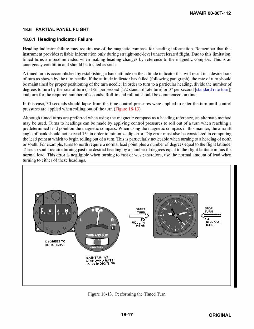
NAVAIR 00-80T-112
ORIGINAL18-17
18.6 PARTIAL PANEL FLIGHT
18.6.1 Heading Indicator Failure
Heading indicator failure may require use of the magnetic compass for heading information. Remember that thisinstrument provides reliable information only during straight-and-level unaccelerated flight. Due to this limitation,timed turns are recommended when making heading changes by reference to the magnetic compass. This is anemergency condition and should be treated as such.
A timed turn is accomplished by establishing a bank attitude on the attitude indicator that will result in a desired rateof turn as shown by the turn needle. If the attitude indicator has failed (following paragraph), the rate of turn shouldbe maintained by proper positioning of the turn needle. In order to turn to a particular heading, divide the number ofdegrees to turn by the rate of turn (1-1/2° per second [1/2 standard rate turn] or 3° per second [standard rate turn])and turn for the required number of seconds. Roll-in and rollout should be commenced on time.
In this case, 30 seconds should lapse from the time control pressures were applied to enter the turn until controlpressures are applied when rolling out of the turn (Figure 18-13).
Although timed turns are preferred when using the magnetic compass as a heading reference, an alternate methodmay be used. Turns to headings can be made by applying control pressures to roll out of a turn when reaching apredetermined lead point on the magnetic compass. When using the magnetic compass in this manner, the aircraftangle of bank should not exceed 15° in order to minimize dip error. Dip error must also be considered in computingthe lead point at which to begin rolling out of a turn. This is particularly noticeable when turning to a heading of northor south. For example, turns to north require a normal lead point plus a number of degrees equal to the flight latitude.Turns to south require turning past the desired heading by a number of degrees equal to the flight latitude minus thenormal lead. This error is negligible when turning to east or west; therefore, use the normal amount of lead whenturning to either of these headings.
STARTTURN
STOPTURN
Figure 18-13. Performing the Timed Turn

NAVAIR 00-80T-112
ORIGINAL 18-18
18.6.2 Attitude Indicator Failure
The attitude indicator is the single most important instrument required for instrument flight. Since failures of theattitude gyro do occur, all pilots must be proficient at controlling the aircraft under instrument conditions without theuse of this instrument. The primary attitude control (nose and wing) in partial panel will consist of one instrumentfor the primary nose attitude indication and another for wing attitude. Figure 18-14 shows the function of theinstruments in a scan pattern with the attitude gyro inoperative. The table is applicable to all Navy aircraft for generalinstrumentation. When flying under partial panel conditions, the pilot should anticipate the desired indications on theperformance instruments due to the slight lag inherent in these instruments. Failure to do so will usually result inovercontrol of the aircraft.
Maneuver Attitude
PrimaryAttitude
Instrument
Attitude Cross-CheckInstrument
PerformanceInstruments
SupportingInstruments
Straight andlevel
Nose Altimeter,VSI Airspeed Power,
MagneticCompassWing Needle-ball Heading
indicator
Level turns Nose Altimeter,VSI
Airspeed,Heading indicator,
Clock
Power, MagneticCompassWing Needle-ball
Straight climbsand descents
Nose Airspeed Altimeter, VSI
Power, MagneticCompassWing Needle-ball Heading
indicator
Climbing ordescending
turns
Nose Airspeed Altimeter,VSI,
Heading indicator
Power, MagneticCompassWing Needle-ball
Figure 18-14. Function of Instruments — Partial Panel
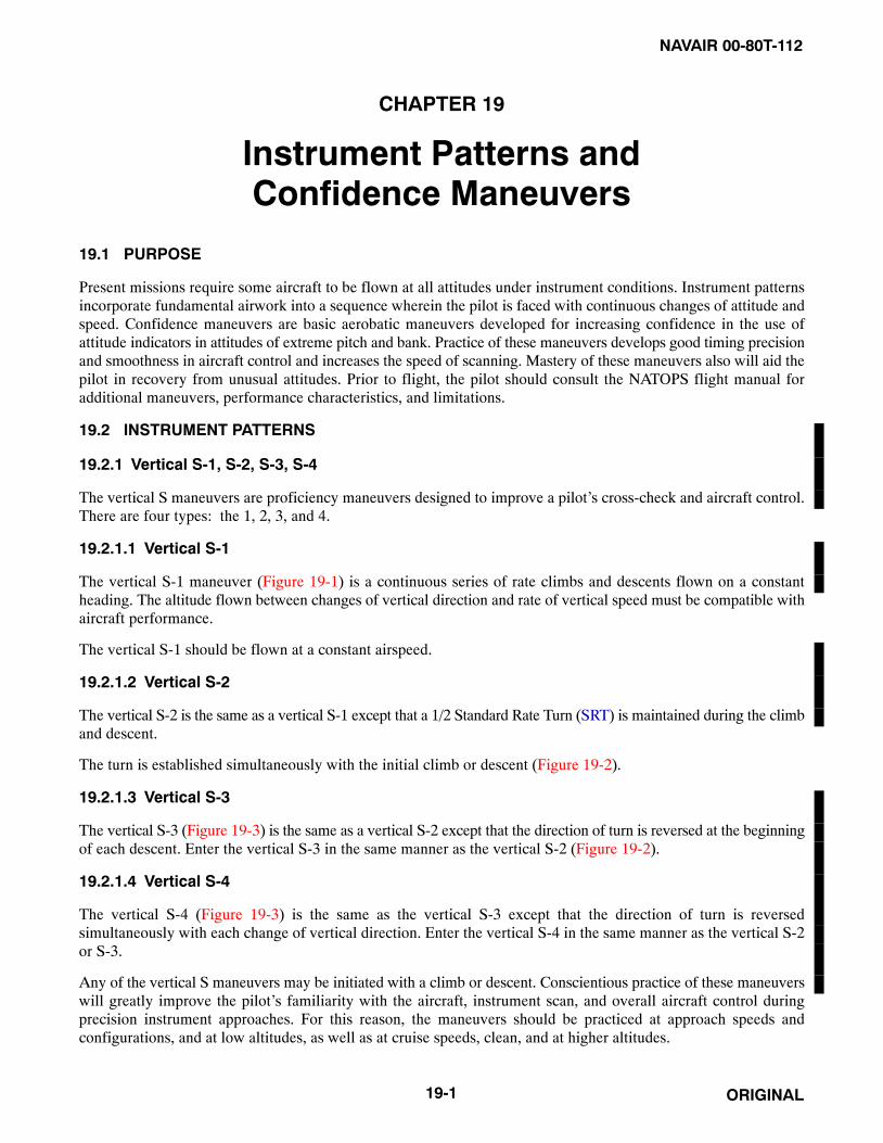
NAVAIR 00-80T-112
ORIGINAL19-1
CHAPTER 19
Instrument Patterns andConfidence Maneuvers
19.1 PURPOSE
Present missions require some aircraft to be flown at all attitudes under instrument conditions. Instrument patternsincorporate fundamental airwork into a sequence wherein the pilot is faced with continuous changes of attitude andspeed. Confidence maneuvers are basic aerobatic maneuvers developed for increasing confidence in the use ofattitude indicators in attitudes of extreme pitch and bank. Practice of these maneuvers develops good timing precisionand smoothness in aircraft control and increases the speed of scanning. Mastery of these maneuvers also will aid thepilot in recovery from unusual attitudes. Prior to flight, the pilot should consult the NATOPS flight manual foradditional maneuvers, performance characteristics, and limitations.
19.2 INSTRUMENT PATTERNS
19.2.1 Vertical S-1, S-2, S-3, S-4
The vertical S maneuvers are proficiency maneuvers designed to improve a pilot’s cross-check and aircraft control.There are four types: the 1, 2, 3, and 4.
19.2.1.1 Vertical S-1
The vertical S-1 maneuver (Figure 19-1) is a continuous series of rate climbs and descents flown on a constantheading. The altitude flown between changes of vertical direction and rate of vertical speed must be compatible withaircraft performance.
The vertical S-1 should be flown at a constant airspeed.
19.2.1.2 Vertical S-2
The vertical S-2 is the same as a vertical S-1 except that a 1/2 Standard Rate Turn (SRT) is maintained during the climband descent.
The turn is established simultaneously with the initial climb or descent (Figure 19-2).
19.2.1.3 Vertical S-3
The vertical S-3 (Figure 19-3) is the same as a vertical S-2 except that the direction of turn is reversed at the beginningof each descent. Enter the vertical S-3 in the same manner as the vertical S-2 (Figure 19-2).
19.2.1.4 Vertical S-4
The vertical S-4 (Figure 19-3) is the same as the vertical S-3 except that the direction of turn is reversedsimultaneously with each change of vertical direction. Enter the vertical S-4 in the same manner as the vertical S-2or S-3.
Any of the vertical S maneuvers may be initiated with a climb or descent. Conscientious practice of these maneuverswill greatly improve the pilot’s familiarity with the aircraft, instrument scan, and overall aircraft control duringprecision instrument approaches. For this reason, the maneuvers should be practiced at approach speeds andconfigurations, and at low altitudes, as well as at cruise speeds, clean, and at higher altitudes.

NAVAIR 00-80T-112
ORIGINAL 19-2
Figure 19-1. Vertical S-1
CONSTANT BANK AND DESCENT
LEVEL FLIGHT
CONSTANT BANK AND CLIMB
CHANGE OF VERTICAL DIRECTIONA
B
C
D
Figure 19-2. Vertical S-2

NAVAIR 00-80T-112
ORIGINAL19-3
A CONSTANT BANK AND DESCENT
CHANGE OF VERTICAL DIRECTIONB CONSTANT BANK AND DESCENTC
CONSTANT BANK AND CLIMBD
FOR S-4REVERSE BANKAT EACHCHANGE OFVERTICALDIRECTION
Figure 19-3. Vertical S-3 and S-4

NAVAIR 00-80T-112
ORIGINAL 19-4
19.2.2 Steep Turns
A steep turn is one in which the angle of bank used is larger than that required for normal instrument flying. In mostaircraft, 30� is the normal maximum angle of bank used because of the ease of control and precision afforded.
Entry into a steep turn is accomplished the same as for a normal turn. As the bank is increased past normal, greaterloss of vertical lift occurs, requiring more pitch adjustment. The use of trim in steep turns varies with individualaircraft characteristics and pilot technique. Additional power will be required to maintain airspeed as the bank isincreased.
Bank should be held constant because varying the angle of bank during the turn contributes significantly to difficultyin pitch control. Precession error in the attitude indicator is more pronounced during steep turns. If altitude deviationbecomes excessive, reduce the angle of bank as necessary to regain positive pitch control.
When rolling out of a steep turn, be alert to correct for the higher-than-normal pitch attitude and power used duringthe turn. Roll out at the same rate used with normal turns. The performance instruments should be scanned closelyduring rollout, as the attitude indicator may have considerable precession error (Figure 19-4).
19.2.3 OSCAR Pattern
OSCAR pattern (Figure 19-5) is entered in the following sequence:
1. Enter pattern on base altitude at normal cruise.
2. Climbing left SRT, gain 1,000 feet.
3. 1 to 2 minutes straight and level at slow cruise.
Figure 19-4. Steep Turn Pattern
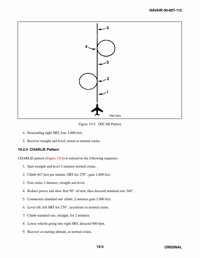
NAVAIR 00-80T-112
ORIGINAL19-5
Figure 19-5. OSCAR Pattern
4. Descending right SRT, lose 1,000 feet.
5. Recover straight and level; return to normal cruise.
19.2.4 CHARLIE Pattern
CHARLIE pattern (Figure 19-6) is entered in the following sequence:
1. Start straight and level 2 minutes normal cruise.
2. Climb 667 feet per minute, SRT for 270�, gain 1,000 feet.
3. Fast cruise 2 minutes, straight and level.
4. Reduce power and slow first 90� of turn, then descend standard rate 360�.
5. Commence standard rate climb; 2 minutes gain 1,000 feet.
6. Level off, left SRT for 270�, accelerate to normal cruise.
7. Climb standard rate, straight, for 2 minutes.
8. Lower wheels going into right SRT, descend 800 fpm.
9. Recover at starting altitude, at normal cruise.
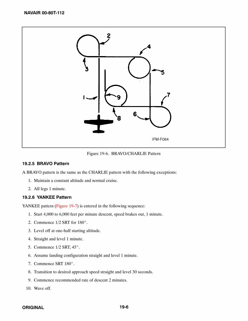
NAVAIR 00-80T-112
ORIGINAL 19-6
Figure 19-6. BRAVO/CHARLIE Pattern
19.2.5 BRAVO Pattern
A BRAVO pattern is the same as the CHARLIE pattern with the following exceptions:
1. Maintain a constant altitude and normal cruise.
2. All legs 1 minute.
19.2.6 YANKEE Pattern
YANKEE pattern (Figure 19-7) is entered in the following sequence:
1. Start 4,000 to 6,000 feet per minute descent, speed brakes out, 1 minute.
2. Commence 1/2 SRT for 180�.
3. Level off at one-half starting altitude.
4. Straight and level 1 minute.
5. Commence 1/2 SRT, 45�.
6. Assume landing configuration straight and level 1 minute.
7. Commence SRT 180�.
8. Transition to desired approach speed straight and level 30 seconds.
9. Commence recommended rate of descent 2 minutes.
10. Wave off.

NAVAIR 00-80T-112
ORIGINAL19-7
Figure 19-7. YANKEE Pattern (High-Performance Aircraft)
19.3 CONFIDENCE MANEUVERS
NoteThe following maneuvers are not applicable to rotary-wing aircraft.
19.3.1 Wingover
The wingover is a combination climbing and diving turn with approximately 180� of heading change (Figure 19-8).The maneuver is commenced from straight-and-level flight after obtaining the desired airspeed. Start a steep climbingturn in either direction so that the heading of the aircraft has changed approximately 90� as the aircraft approaches90� angle of bank. When the angle of bank reaches 90�, allow the nose of the aircraft to start down. As the nose ofthe aircraft passes through the horizon, smoothly decrease the angle of bank to a wings-level attitude. The rate of rollduring the recovery should be the same as the rate of roll used during the entry.
19.3.2 Barrel Roll
The barrel roll is a combination climbing and diving maneuver that is accomplished by smoothly rolling the aircraftabout a point 45� off the aircraft heading on the horizon. The maneuver is accomplished by commencing asimultaneous climb and roll at a rate that will achieve a 90� change of heading as the aircraft completes 180� of roll(inverted flight). The nose should reach a point about 45� above the horizon as 90� of roll is completed. As the nosedrops below the horizon, the roll should be continued and backpressure increased as necessary to place the aircraftstraight and level at the completion of the roll (Figure 19-9).
NoteThis maneuver should be attempted only in aircraft equipped with thethree-axis Attitude Direction Indicator (ADI).

NAVAIR 00-80T-112
ORIGINAL 19-8
A 60° BANK
BANK INCREASING TO 90°(NOSE COMING DOWN)B 90° BANKC BANK DECREASING
(NOSE LOW)D
60° BANK RECOVERINGE
Figure 19-8. Wingover
A BEGIN ROLL
180° OF ROLL (INVERTED)90° CHANGE OF HEADING
B
RECOVERINGC
RECOVERYD
B
AC
D
Figure 19-9. Barrel Roll

NAVAIR 00-80T-112
ORIGINAL19-9
19.3.3 Aileron Roll
Begin the maneuver from straight-and-level flight after obtaining the desired airspeed. Smoothly increase the pitchattitude with the wings level and as directed by the applicable NATOPS flight manual. Start a roll in either directionand adjust the rate of roll so that, when inverted, the wings will be level as the fuselage dot of the miniature aircraftpasses through the horizon bar. Continue the roll and recover in a nose-low, wings-level attitude (Figure 19-10). Theentire maneuver should be accomplished by reference to the attitude indicator. The rate of roll should be constant andcontinuous throughout the maneuver.
19.3.4 Loops
Advance the power and lower the nose to attain a desired entry airspeed compatible with aircraft performance. Referto the attitude indicator and smoothly raise the nose to the horizon with the wings level. Upon reaching the horizon,increase back-pressure, ensuring sufficient g’s are applied to pull the aircraft up through the vertical and over the topof the loop without exceeding aircraft limitations (Figure 19-11).
Bear in mind that some attitude indicators reverse themselves by controlled precession as the aircraft passes througha vertical attitude. It is essential that the aircraft wings are level prior to and after this reversal. An easy method ofkeeping the wings level is to keep the bank pointer centered at the top of the attitude indicator prior to reversal andthen keeping it centered at the bottom after reversal. Be alert to recognize and then disregard the attitude indicationsduring this short period of controlled precession.
As the airspeed decreases in the pullup, pitch control may become less effective and further backpressure may berequired to maintain constant g force. As the airspeed drops to the point where the g can no longer be maintained inthe control region without stalling, release some backpressure.
A BEGIN ROLL 90° OF ROLLB INVERTEDC RECOVERYD
Figure 19-10. Aileron Roll

NAVAIR 00-80T-112
ORIGINAL 19-10
D 90° CLIMB INVERTEDE INVERTED DIVEF DIVEG
A LEVEL FLIGHT 40° CLIMBB 60° CLIMBC
Figure 19-11. Loop

NAVAIR 00-80T-112
ORIGINAL19-11
A INVERTED (NOSE SLIGHTLY BELOWHORIZON, BEGIN ROLLOUT)
90° OF ROLLB RECOVER(NOSE LOW)C
Figure 19-12. Immelmann Recovery
Ensure sufficient backpressure remains to fly the aircraft through the top of the loop with a safe margin of airspeedabove the stall. In some aircraft, rudder application may be necessary to maintain balanced flight throughout themaneuver.
After passing through the inverted attitude at the top of the loop, gradually increase the backpressure as the airspeedincreases. Recover from the resultant dive, being alert for controlled precession on the attitude indicator as the aircraftpasses through the vertical attitude. Keep the aircraft wings level throughout the maneuver, being careful not toexceed any aircraft limitations.
NoteConsidering varying load conditions with resultant accelerated stall speedsand feel/buffet changes, reference to the angle of attack indicator in aircraftso equipped is recommended during critical segments of the loop.
19.3.5 Immelmann
The Immelmann (Figure 19-12) is executed in the same manner as the first half of a loop followed by a half roll toan upright attitude. Maintain inverted flight through the top of the maneuver until just before the fuselage dot of theminiature aircraft passes through the horizon bar. Release backpressure upon approaching the horizon and roll to anupright level attitude. Do not reduce power until the maneuver is completed.
19.3.6 Half Cuban Eight
The Half Cuban Eight is the first half of a loop with a rollout from the inverted nosedown attitude, resulting in a 180�heading change. It differs from the Immelmann turn in that the rollout is in a nose-low attitude rather than a levelattitude. This maneuver is practiced to develop the pilot’s confidence in the attitude indicator (Figure 19-13).

NAVAIR 00-80T-112
ORIGINAL 19-12
AL
EV
EL
FL
IGH
T
40°
CL
IMB
B
60°
CL
IMB
C
90°
CL
IMB
D
EIN
VE
RT
ED
FIN
VE
RT
ED
DIV
E
GR
OL
LO
UT
H(1
80°
CH
AN
GE
OF
HE
AD
ING
)R
EC
OV
ER
NO
SE
LE
VE
L
A
B
C
D
E
F
G
H
Figure 19-13. Half Cuban Eight
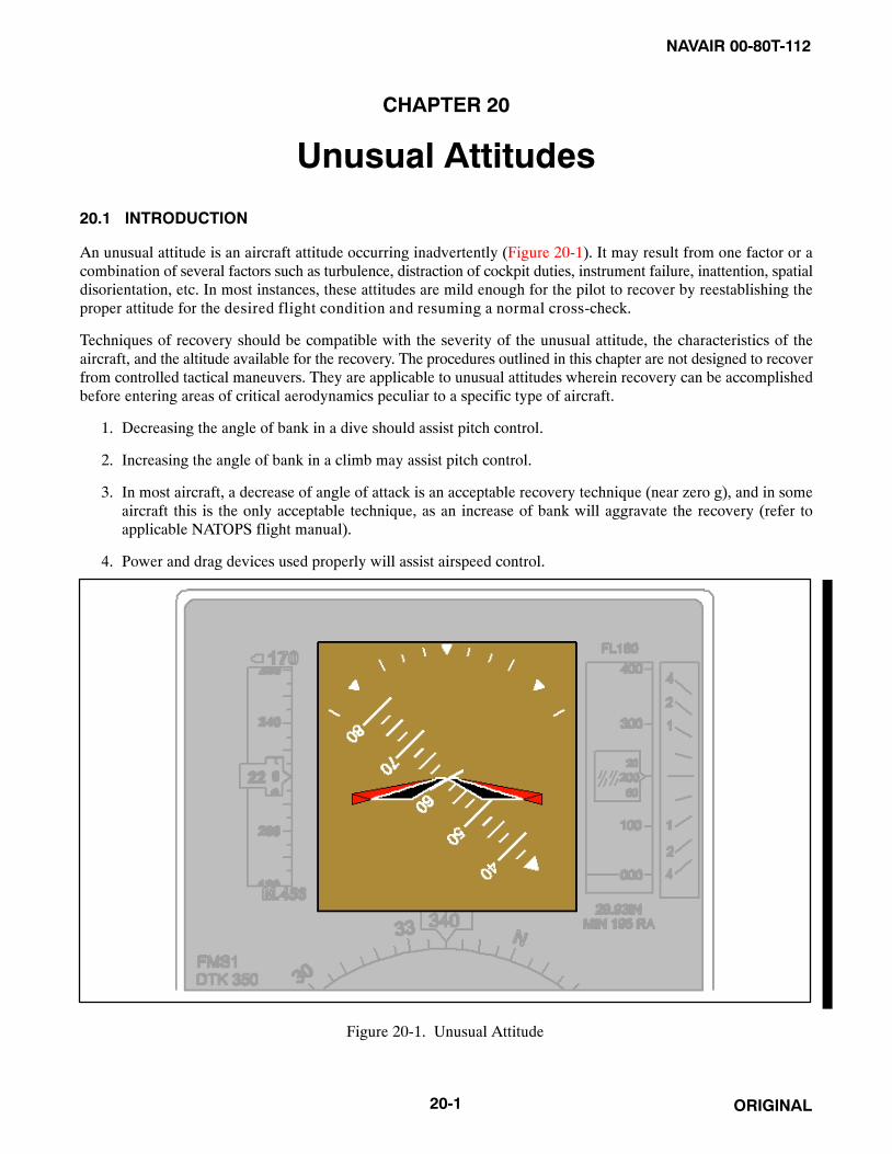
NAVAIR 00-80T-112
ORIGINAL20-1
CHAPTER 20
Unusual Attitudes
20.1 INTRODUCTION
An unusual attitude is an aircraft attitude occurring inadvertently (Figure 20-1). It may result from one factor or acombination of several factors such as turbulence, distraction of cockpit duties, instrument failure, inattention, spatialdisorientation, etc. In most instances, these attitudes are mild enough for the pilot to recover by reestablishing theproper attitude for the desired flight condition and resuming a normal cross-check.
Techniques of recovery should be compatible with the severity of the unusual attitude, the characteristics of theaircraft, and the altitude available for the recovery. The procedures outlined in this chapter are not designed to recoverfrom controlled tactical maneuvers. They are applicable to unusual attitudes wherein recovery can be accomplishedbefore entering areas of critical aerodynamics peculiar to a specific type of aircraft.
1. Decreasing the angle of bank in a dive should assist pitch control.
2. Increasing the angle of bank in a climb may assist pitch control.
3. In most aircraft, a decrease of angle of attack is an acceptable recovery technique (near zero g), and in someaircraft this is the only acceptable technique, as an increase of bank will aggravate the recovery (refer toapplicable NATOPS flight manual).
4. Power and drag devices used properly will assist airspeed control.
Figure 20-1. Unusual Attitude

NAVAIR 00-80T-112
ORIGINAL 20-2
20.2 ATTITUDE INTERPRETATION
Normally, an unusual attitude is recognized in one of two ways: an unusual attitude picture on the attitude indicatoror unusual performance on the performance instruments. Regardless of how the attitude is recognized, verify anunusual attitude exists by comparing control and performance instrument indications prior to initiating recovery onthe attitude indicator. This precludes entering an unusual attitude as a result of making control movements to correctfor erroneous instrument indications. During this process, the attitude must correctly be interpreted. Additionalattitude indicating sources (standby attitude indicator, copilot attitude indicator, etc.) should be used. If there is anydoubt as to proper attitude indicator operation, recovery should be made using attitude indicator inoperativeprocedures.
The following techniques will aid aircraft attitude interpretation on the attitude indicator:
1. For attitude indicators with a single bank pointer and bank scale at the top, the bank pointer can be considereda sky pointer. It always points up and should be in the upper half of the case. Rolling toward the bank pointerto place it in the upper half of the case will correct an inverted attitude.
2. For those attitude indicators with the bank scale at the bottom, rolling in the direction that will place the pitchreference scale right-side up will correct an inverted attitude (Figure 20-2).
Ease of pitch interpretation varies with the type of attitude indicator installed. Attitude indicators having pitchreference scales in degrees and grey/black attitude spheres can easily be interpreted for climb or dive indications. Forthose aircraft not so equipped, the airspeed indicator, altimeter, or vertical speed indicator generally present the mosteasily interpreted indications of a climb or a dive. Attitude interpretation is a skill that must be highly developed bypractice in flight or on the ground in simulators or with mockups.
20.3 RECOVERY PROCEDURES
Unusual attitudes are generally classified as nose high or nose low. Each has distinct recovery techniques that aregenerally applicable to all aircraft. Refer to the NATOPS flight manual for specific recovery procedures.
20.3.1 Nose-High Recovery
Factors to consider in nose-high recoveries are pitch attitude and airspeed. If the pitch attitude is not extreme andairspeed is not approaching the stall ranges, recovery can be considered to be a normal nose-high attitude.
To recover from a normal nose-high unusual attitude, use power as necessary, and smoothly lower the nose towardthe level flight attitude. As the nose approaches the level flight attitude, level the wings and readjust power asnecessary.
If the pitch attitude is extreme or airspeed is approaching the stall range, recovery can be considered to be for anextreme nose-high attitude.
To recover from an extreme nose-high unusual attitude, roll the aircraft in the shortest direction toward the wingoverposition. As the nose falls through the horizon, level the wings and raise the nose to the level flight attitude. Use poweras necessary throughout the recovery.
NoteFor swept-wing aircraft, the wingover recovery method is not acceptable.Instead, a decrease in angle of attack (zero g) is used until sufficientairspeed is gained to prevent an accelerated stall or spin condition. Forfurther information, consult the applicable NATOPS flight manual.

NAVAIR 00-80T-112
ORIGINAL20-3
ROLLING TO PLACE THE PITCHREFERENCE SCALE “RIGHT SIDE UP”WILL CORRECT AN INVERTED ATTITUDE.
ADI
Figure 20-2. Bank Attitude Interpretation

NAVAIR 00-80T-112
ORIGINAL 20-4
20.3.2 Nose-Low Recovery
Factors to be considered in recovering from nose-low unusual attitudes are altitude and g loading during pullout. Ifaltitude permits, avoid rolling pullouts, as allowable stresses in an angle of bank are considerably lower than thoseallowed in a wings-level pullout.
To recover from a nose-low unusual attitude, roll to a wings-level upright position, then raise the nose to the levelflight attitude. Adjust power and/or drag devices as appropriate.
During unusual attitude recoveries, the pilot should coordinate the amount of bank and power used with the rate atwhich airspeed and pitch are being controlled. Bank and power used must be compatible with aircraft and enginecharacteristics.
NoteFor helicopters encountering blade stall, in a nose-high attitude, collectivepitch (power) must be reduced before applying attitude corrections. Toavoid blade stall when recovering from steep diving attitudes, reducecollective pitch and bank attitude before initiating a pitch change. In allcases, avoid abnormal positive g loads; prevent negative g loads andinverted flight.
20.3.3 Partial Panel Unusual Attitudes
With an inoperative attitude indicator, successful recovery from unusual attitudes depends greatly on pilot proficiencyand early recognition of attitude indicator failure. For example, attitude indicator failure should immediately besuspected if control pressures were applied for a turn without corresponding attitude indicator changes. Anotherexample would be satisfactory performance instrument indications that contradict the picture on the attitude indicator.
20.3.3.1 Recovery Procedures — Partial Panel
Should an unusual attitude be encountered with an inoperative attitude indicator, determine whether the aircraft isin a climb or a dive by reference to the airspeed, altimeter, and vertical speed indicators.
If nose low, roll to center the turn needle and recover from the dive. Adjust power and/or drag devices as appropriate.
If nose high, use power as required. Apply controls as necessary to decrease the aircraft g to not less than zero g. Afterreaching level flight and if the aircraft is in a turn, smoothly roll to center the turn needle; reversal of the altimeterand vertical speeds tends to indicate passage of a level flight attitude. (Refer to the appropriate NATOPS flight manualfor detailed aircraft limitations.)
As the level flight attitude is approached, as indicated by the decrease in rate of change of airspeed and altitude, acorrection will be required to prevent chasing the vertical speed indicator. For example, in recovery from a nose-lowunusual attitude, once the turn needle has been centered, back stick pressure is applied until the performanceindicators show the approach of level flight. Because of the slight lag inherent in these instruments, the pilot shouldanticipate the performance instruments and apply opposite pressure as the indicators show the approach of the levelflight attitude. Failure to do so will usually result in the progressing from one unusual attitude to another (in thisexample, from nose low to nose high).
Spatial disorientation may become severe during the recovery fromunusual attitudes with an inoperative attitude indicator. Extreme attitudesmay result in an excessive loss of altitude and possible loss of aircraftcontrol; therefore, the pilot should decide upon an altitude at whichrecovery attempts will be discontinued and the aircraft abandoned.

NAVAIR 00-80T-112
ORIGINAL77/(78 blank)
PART VI
Navigational Aids/Facilities and Procedures
Chapter 21 — VHF Omnidirectional Range (VOR)
Chapter 22 — Tactical Air Navigation (TACAN)
Chapter 23 — ADF, UHF/ADF, Marker Beacons
Chapter 24 — Instrument Landing System (ILS)
Chapter 25 — Radar Approaches
Chapter 26 — Global Positioning System (GPS)

NAVAIR 00-80T-112
ORIGINAL1/(2 blank)

NAVAIR 00-80T-112
ORIGINAL21-1
CHAPTER 21
VHF Omnidirectional Range (VOR)
21.1 INTRODUCTION
The VHF Omnidirectional Range (VOR) is a radio facility that eliminated many of the difficulties previouslyencountered when navigating with the radio compass. VOR course information is not affected by weather or otherfactors common to ADF. With a course indicator, it is possible to select and precisely fly any 1 of 360 courses to orfrom a VOR.
21.2 EQUIPMENT AND OPERATION
21.2.1 Equipment
The VOR provides 360 courses that radiate from the station like spokes from the hub of a wheel. These courses, knownas radials, are identified by their magnetic bearing from the station; thus, regardless of heading, an aircraft on the 90_radial is physically located due east of the station. Flying to the station on this radial, the magnetic course is 270_.As the transmitting equipment is in the VHF band, the signals are free of atmospheric disturbances but subject toline-of-sight reception. Reception range varies according to the altitude of the aircraft (Figure 21-1).
Figure 21-1. Radials

NAVAIR 00-80T-112
ORIGINAL 21-2
21.2.1.1 Principle of Operation
The transmission principle of the VOR is based on the creation of a phase difference between two signals. One ofthese signals, the reference phase, is omnidirectional and radiates from the station in a circular pattern. The phase ofthis signal is constant throughout 360�. The other signal, the variable phase, rotates uniformly at 1,800 rpm, whichcauses its phase to vary at a constant rate.
Magnetic north is used as the baseline for electronically measuring the phase relationship between the reference andvariable phase signals. At magnetic north, the signals are exactly in phase; however, a phase difference exists at anyother point around the station. This phase difference is measured electronically by the aircraft receiver and displayedon the navigation instruments (Radio Magnetic Indicator [RMI], course indicator, etc.) (Figure 21-2).
21.2.1.2 Control Panel
Typical VOR control panels contain a power switch, frequency selector knobs, a frequency window, and a volumecontrol (Figure 21-3).
The VHF navigation frequency band is as follows:
1. ILS — 108.1 to 111.9 MHz (odd tenths).
2. VOR — 108.0 to 117.95 MHz.
Figure 21-2. Signal Phase Angle Relationship

NAVAIR 00-80T-112
ORIGINAL21-3
Figure 21-3. Control Panel
Since a large portion of the frequency band overlaps into the VHF communication band (108.0 to 135.9 MHz), theVOR receiver may be used as a secondary VHF communication receiver.
The volume control knob controls the level of the signals going into the headset only. It has no effect on the signalreception of the VOR receiver.
21.2.2 Operation
21.2.2.1 Tuning
To tune the VOR equipment, flip the power switch ON, select the desired frequency, and identify the station. Thestation identification may be a three-letter Morse code, a recorded voice, or a combination of both. The voiceannouncement alternates with the usual Morse code identification. If no air/ground communications facility isassociated with the VOR, the phrase “UNATTENDED VOR” (VORTAC) precedes the station name. Positivelyidentify the selected station. Through human error or equipment malfunction, it is possible that the station intendedto be selected is not the one being received. This may occur as the result of failing to select the correct frequency orfailure of the receiver to channel to the new frequency.
After identifying the VOR station, an unreliable signal can be identified on the instrument (refer to specific aircraftNATOPS). Some VOR stations transmit Transcribed Weather Broadcasts (TWEBs), Hazardous In-Flight WeatherAdvisory Service (HIWAS), Airmen’s Meteorological Information (AIRMETs), Significant MeteorologicalInformation (SIGMETs), and possibly communications from air traffic control.
NoteDuring periods of maintenance, the coded identification is removed.

NAVAIR 00-80T-112
ORIGINAL 21-4
After the set is tuned, check the bearing pointer, Course Deviation Indicator (CDI), and TO-FROM indicator forproper operation. The bearing pointer should point to the magnetic bearing to the station. The CDI should center whenthis bearing is set in the course selector window, and the TO-FROM indicator should indicate TO.
NoteAlthough the RMI is used with the course indicator in the accompanyingtext and illustrations, the Bearing-Distance-Heading Indicator (BDHI)display of bearing information is identical.
21.2.2.2 VOR/DME Paired Frequencies
Distance Measuring Equipment (DME) consists of airborne and ground equipment, usually co-located. The DMEprovides distance (and in some systems groundspeed) information only from the ground facility. DME operates inthe Ultrahigh Frequency (UHF) band; however, its frequency can be “paired” with VOR or Instrument LandingSystem (ILS) or Localizer (LOC) frequencies. The receiving equipment in most aircraft provide for automatic DMEselection through a coupled VOR/lLS receiver. Selection of the appropriate VOR or ILS frequency automaticallytunes the DME. Some equipment then allows the user to manually tune another VOR/ILS frequency and keep theDME paired to the previously selected VOR/ILS frequency. The UHF/VHF paired frequency chart can be found inthe Flight Information Handbook.
21.3 PROCEDURES
21.3.1 Proceeding Direct to Station
To proceed directly to the station, turn the aircraft in the shorter direction to place the bearing pointer under the topindex of the RMI. Set the bearing read under the head of the bearing pointer into the course selector window. If thisdoes not center the CDI exactly, rotate the course set knob until the CDI does center. Maintain this course to the station.If either the compass card or the bearing pointer is inoperative, the course indicator may be used to determine thebearing to the station by rotating the course set knob until the CDI centers and TO is read in the TO-FROM indicator.The magnetic bearing from the aircraft to the station then appears in the course selector window (Figure 21-4).
21.3.2 Course Interceptions
Course interceptions are performed in most phases of instrument navigation. The equipment used varies, but anintercept heading must be flown that results in an angle or rate of intercept sufficient to solve a particular problem.
Rate of intercept, seen by the pilot as bearing pointer or CDI movement, is a result of the following factors:
1. The angle at which the aircraft is flown toward a desired course (angle of intercept).
2. True airspeed and wind (groundspeed).
3. Distance from the station.
The angle of intercept is the angle between the heading of the aircraft (intercept heading) and the desired course.Controlling this angle by selection and/or adjustment of the intercept heading is the easiest and most effective wayto control course interceptions. Angle of intercept must be greater than the degrees from course, but should not exceed90�. At 90�, rate of intercept is the maximum possible. Within this limit, adjust to achieve the most desirable rateof intercept.
When selecting an intercept heading, the key factor is the relationship between distance from the station and degreesfrom the course. Each degree, or radial, is 1 nm wide at a distance of 60 nm from the station. Width increases ordecreases in proportion to the 60 nm distance. For example, 1� is 2 nm wide at 120 nm and 1/2 nm wide at 30 nm.For a given groundspeed and angle of intercept, the resultant rate of intercept varies according to the distance fromthe station.

NAVAIR 00-80T-112
ORIGINAL21-5
1
2
3
4
TURN TO PLACEBEARING POINTERUNDER TOP INDEX.
ROTATE COURSESET KNOB TOCENTER THE CDI.
MAINTAIN COURSEINBOUND TO THESTATION.
TUNE TO NEW FREQUENCY.
Figure 21-4. Proceeding Direct to Station

NAVAIR 00-80T-112
ORIGINAL 21-6
When selecting an intercept heading to form an angle of intercept, consider the following factors:
1. Degrees from course.
2. Distance from the station.
3. True airspeed and wind (groundspeed).
21.3.3 Inbound Procedures
To intercept a radial while flying to a station, a number of varying methods may be employed. Generally, setting upa 45� angle of intercept is recommended; 30� angle of intercept is equally correct, as is the double the angle off thebow method if the number of radials to be crossed is not in excess of 45. The double-the-angle-off-the-bow methodis described in detail in Chapter 22, as is the timed distance method for radial changes in excess of 45�.
21.3.3.1 RMI Only
Inbound course interceptions utilizing only the RMI are described in detail in Figure 21-5. The essential element isto visualize the problem utilizing the RMI center as the station and the tail of the bearing pointer as the present aircraftposition. Then a pilot can visualize the new radial that the pilot wants to intercept as is done in Tactical Air Navigation(TACAN) point to point. As distances are not known, a standard 45� angle of intercept is recommended. It isimportant to disregard aircraft heading until the intercept heading is computed. Then, turn in the shortest directionto that heading.
21.3.3.2 RMI and CDI
Inbound course interceptions utilizing RMI and CDI are described in detail in Figure 21-6. Essentially these can beaccomplished exactly as under RMI only with the additional aid of using the CDI in the final phase.
21.3.3.3 CDI Only
Inbound course interceptions utilizing the CDI only are described in detail in Figure 21-7. The essential element isto visualize the problem on an RMI or on any compass card and then proceed as under RMI and CDI. Some CDIsdo not have heading pointers and some VOR sets do not employ a bearing pointer. In these cases, it is essential todisregard aircraft heading until the intercept heading is determined. Then, turn in the shortest direction to that heading(utilizing a timed turn if all compass cards are inoperative).
21.3.4 Outbound Procedures — Immediately After Station Passage
Intercepting courses immediately after station passage does not require large intercept angles. Because of radialconvergence, actual aircraft displacement from course is relatively small compared to bearing pointer or CDIindications. For example, a 30� off-course indication when 2 nm from the station represents approximately 1 nm offcourse.
Paralleling the desired outbound course while allowing the bearing pointer or CDI to stabilize is acceptable. If thismethod is utilized, proceed as outlined below for outboard course interceptions.
Continuing to turn to intercept the outbound course may be preferred in order to expedite the intercept. This methodis described in Figure 21-8.
Utilize the RMI or CDI as available. Use an angle or intercept equal to the number of degrees of radial change desired;however, to prevent overshooting, do not turn more than 45� beyond the heading required to parallel course.

NAVAIR 00-80T-112
ORIGINAL21-7
Figure 21-5. Inbound Course Interception (RMI Only) (Sheet 1 of 2)

NAVAIR 00-80T-112
ORIGINAL 21-8
Inbound Procedural Steps — RMI Only
1. Tune and identify the VOR station.
The bearing pointer will then point to the magnetic course to the station as it appears on the RMI;heading has nothing to do with the radial the aircraft is on. The aircraft can be visualized on the tail of thebearing pointer with the station at the center of the RMI.
2. Determine intercept heading.
Determine which radial the aircraft is on by noting the tail of the bearing pointer. Determine the requireddirection of turn to the new radial. An intercept angle is formed when the head of the bearing pointer isbetween the desired course and the top index of the RMI.
3. Determine and set in the new course.
4. Turn in the shortest direction to the intercept heading.
Set up a 45-degree, 30-degree, or double-the-angle-off-the-bow intercept.
5. Maintain the intercept heading until a lead point is reached, then complete the intercept.
Lead point depends on bearing pointer rate of movement and the time required to turn on course.
Figure 21-5. Inbound Course Interception (RMI Only) (Sheet 2 of 2)

NAVAIR 00-80T-112
ORIGINAL21-9
TO
TO
Figure 21-6. Inbound Course Interception (Course Indicator and RMI) (Sheet 1 of 2)

NAVAIR 00-80T-112
ORIGINAL 21-10
TO
TO
INTERCEPTCOMPLETED
4
5
Inbound Procedural Steps — Course Indicator and RMI
1. Tune and identify the VOR station.
The bearing pointer will function as described in Figure 21-5.
2. Set the desired inbound course in the course selector window and check for a TO indication.
3. Determine intercept heading as described in Figure 21-5.
4. Turn in the shortest direction to the intercept heading.
The CDI heading pointer should be positioned on the upper half of the CDI when established in theintercept heading. Both the heading pointer and course bar must be on the same side of the CDI whileintercepting the desired course. The CDI heading pointer should be deflected in a manner thatcorresponds to the angle of intercept.
5. Maintain the intercept heading until a lead point is reached, then complete the intercept.
Lead point depends on bearing pointer/CDI rate of movement and the time required to turn on course.
Figure 21-6. Inbound Course Interception (Course Indicator and RMI) (Sheet 2 of 2)

NAVAIR 00-80T-112
ORIGINAL21-11
Step 1
6
TO
TO
TO
Figure 21-7. Inbound Course Interception (CDI Only) (Sheet 1 of 2)

NAVAIR 00-80T-112
ORIGINAL 21-12
TO TO
Inbound Procedural Steps — Course Indicator Only
1. Tune and identify the VOR station.
2. Center the CDI with TO in the TO-FROM indicator.
Note the course displayed in the course selector window and visualize on any compass card a bearingpointer pointing to the course displayed and the desired inbound radial.
3. Determine an intercept heading using RMI only procedures.
4. Set the desired inbound course in the course selector window and check for a TO indication.
5. Turn to the intercept heading.
Turn in the shortest direction to the intercept heading. If a CDI heading pointer is installed, ensure thepointer is positioned in the upper half of the CDI when established on the intercept heading.
Note
If all compass cards are inoperative, make a timed turn to the intercept heading usingthe magnetic compass.
6. Maintain the intercept heading until a lead point is reached, then complete the intercept.
Lead point depends on the CDI rate of movement and the same required to turn on course.
Figure 21-7. Inbound Course Interception (CDI Only) (Sheet 2 of 2)

NAVAIR 00-80T-112
ORIGINAL21-13
Step 1
FROM
FROM
Figure 21-8. Course Interception Immediately After Station Passage (Course Indicator and RMI) (Sheet 1 of 2)

NAVAIR 00-80T-112
ORIGINAL 21-14
FROM
FROM
INTERCEPTCOMPLETED
5
Outbound Procedural Steps Immediately After Station Passage — Course Indicator and RMI
1. Tune and identify the VOR station.
This should already be accomplished.
2. Turn in the shortest direction to a heading that will parallel or intercept the outbound course.
Turning to parallel the desired outbound course is acceptable. Continuing the turn to an intercept headingmay be preferable to expedite the intercept. If turning immediately to intercept, utilize an angle ofintercept equal to the number of degrees or radial desired, not to exceed 45 degrees.
3. Set the desired course in the course selector window and check for FROM indication.
4. Turn to an intercept heading, if not previously accomplished.
5. Maintain the intercept heading until a lead point is reached, then complete the intercept.
Lead point depends on bearing pointer/CDI rate of movement and the time required to turn on course.
Figure 21-8. Course Interception Immediately After Station Passage (Course Indicator and RMI) (Sheet 2 of 2)
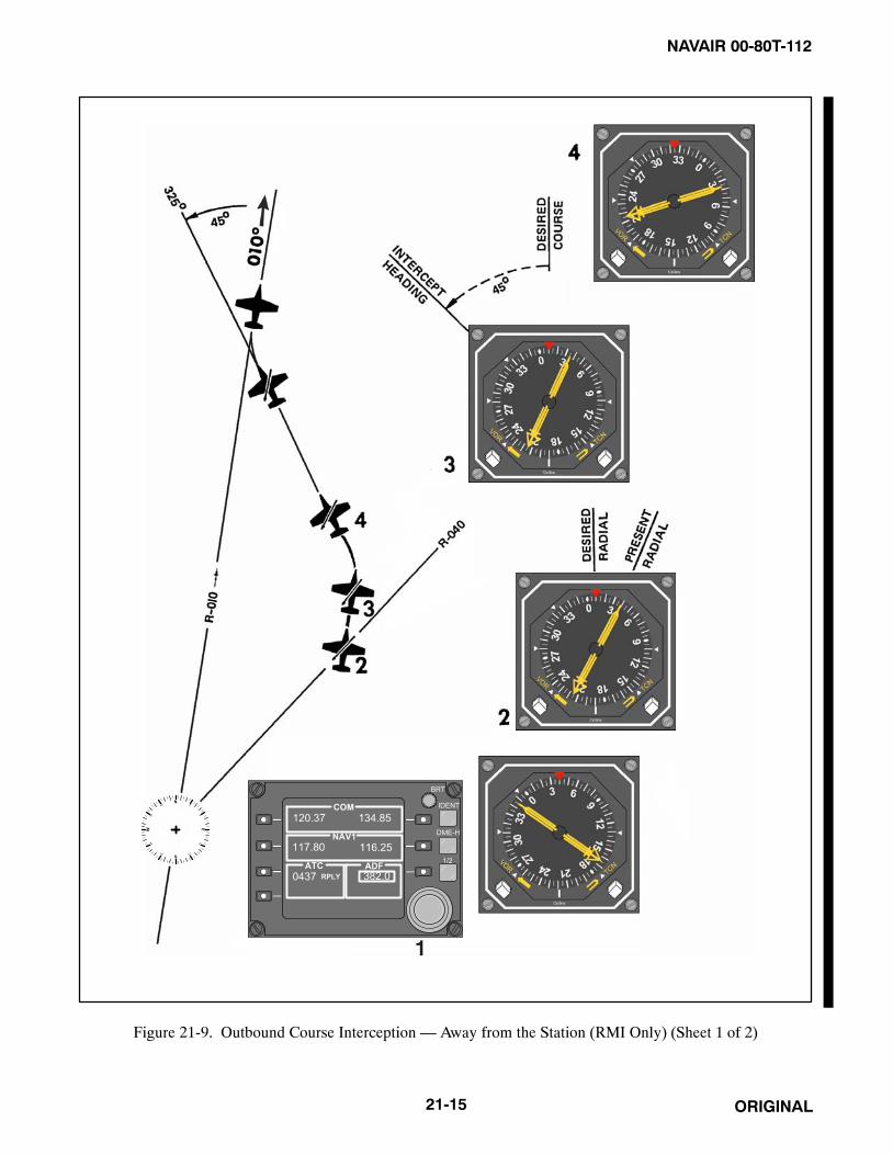
NAVAIR 00-80T-112
ORIGINAL21-15
Figure 21-9. Outbound Course Interception — Away from the Station (RMI Only) (Sheet 1 of 2)

NAVAIR 00-80T-112
ORIGINAL 21-16
Outbound Procedural Steps — RMI Only
1. Tune and identify the VOR station.
2. Determine which radial the aircraft is on by noting the tail of the bearing pointer.
Determine the direction of turn to the new radial.
3. Determine and set in the new course.
4. Turn to the intercept heading in the direction determined in step 2.
Set up a 45-degree, 30-degree, or double-the-angle-off-the-bow intercept.
5. Maintain the intercept heading until a lead point is reached, then complete the intercept.
Lead point depends on bearing pointer rate of movement and the time required to turn on course.
Figure 21-9. Outbound Course Interception — Away from the Station (RMI Only) (Sheet 2 of 2)
21.3.5 Outbound Procedures
To intercept a radial while flying from a station, several methods may be employed. Whereas a 45� angle of interceptis recommended, a 30� angle of intercept or the double the angle off the bow (as described in Figure 21-16) may beused.
21.3.5.1 RMI Only
Outbound radial interceptions utilizing only the RMI are described in detail in Figure 21-9. The essential element isto visualize the problem utilizing the RMI center as the station and the tail of the bearing pointer as the present aircraftposition. Then a pilot can visualize the new radial that the pilot wants to intercept as is done in TACAN point to point.As distances are not known, the pilot can picture the aircraft at the middle of the bearing pointer with the desired pointof interception at the outer edge of the compass card.
21.3.5.2 RMI and CDI
Outbound radial interception utilizing RMI and CDI are described in detail in Figure 21-10. Essentially, these canbe accomplished exactly as described in paragraph 21.3.5.1 with the additional aid of using the CDI in the final phase.
21.3.5.3 CDI Only
Outbound radial interceptions utilizing the CDI only are described in detail in Figure 21-11. The essential elementis to visualize the problem on an RMI or on any compass card and then proceed as under RMI and CDI. Some CDIsdo not have a heading pointer, and some VOR sets do not employ a bearing pointer. In these cases, it is essential todisregard aircraft heading until the intercept heading is determined. Then turn in the shortest direction to that heading(utilizing a timed turn if all compass cards are inoperative).

NAVAIR 00-80T-112
ORIGINAL21-17
21.3.6 Completing the Intercept
After the intercept heading has been established, adjustments may be required to achieve a more desirable angleor rate of intercept. As the aircraft approaches course, determine a lead point for turning because of turn radius.A properly selected lead point will result in the turn being completed as the course is intercepted. Lead point isdetermined by comparing bearing pointer/CDI movement (rate of intercept) to the time required to turn tocourse. Whenever the CDI is fully deflected, monitor the bearing pointer to detect unusually slow or fast ratesof intercept. Remember that the CDI remains fully deflected until the aircraft is within 10� of course. As CDImovement can be accurately compared with angle of intercept displayed by the heading pointer, use the courseindicator for completing intercepts whenever possible. If it is obvious that the lead point selected will result inundershooting the desired course, reduce the angle of bank or roll out of the turn and resume the intercept. If thelead point selected results in an overshoot, continue the turn and roll out with an intercept heading. Aircraft ison course when CDI is centered and/or the bearing pointer points to the desired course. Complete turn to coursewith a correction applied for known wind.
21.3.7 Estimating Drift Correction
After completing the turn to course with the CDI centered, maintain heading until the CDI indicates deviation fromthe selected course. At the first indication of course deviation, turn toward the CDI to reintercept course. Follow thesame procedure used for a normal course interception and consider the same factors (i.e., degrees from course,distance from the station, True Airspeed [TAS], and wind). After returning to course from a deviation caused by wind,reestimate the drift correction and increase or decrease the one previously held. To keep the CDI centered, makefurther corrections from this new heading. When close to the station, the CDI may show a rapid movement from theon-course indication because of radial convergence; however, actual course deviation is probably small, especiallyif wind drift has been solved. Avoid overcorrecting in this situation.
To maintain a course to the station using only the RMI, maintain heading until the bearing pointer shows a deviationfrom the desired course. To return to course, use normal course interception procedures. The aircraft is back on coursewhen the desired course is again shown under the head of the bearing pointer. If you have applied the correct winddrift, the pointer should continue to point to the desired course. If the pointer moves toward the top index, the driftcorrection is too small; if it moves away from the top index, it is too large.
To maintain an outbound course, use outbound course interception procedures. Apply corrections to keep the desiredcourse under the tail of the bearing pointer. After applying a wind drift correction outbound and the tail of the pointermoves toward the top index, the drift correction is too large; if it moves away from the top index, the drift correctionis too small (Figure 21-12).
21.3.8 Homing
After the VOR station is tuned, the VOR bearing pointer will point to the magnetic bearing of the selected station.To home to the station, turn the aircraft to place the head of the bearing pointer under the top index. By keeping thebearing pointer under the index, the station will always be directly ahead of the aircraft. As homing does notincorporate wind drift correction, in a crosswind, the aircraft follows a curved path to the station. Homing is not anapproved IFR procedure and, therefore, should be used only when close to the station (Figure 21-13).

NAVAIR 00-80T-112
ORIGINAL 21-18
FROM
FROM
3
Figure 21-10. Outbound Course Interception — Away from the Station (Course Indicator and RMI) (Sheet 1 of 2)

NAVAIR 00-80T-112
ORIGINAL21-19
FROM
FROM
INTERCEPTCOMPLETED
4
Outbound Procedural Steps — RMI Only
1. Tune and identify the VOR station.
2. Set the desired outbound course in the course selector window.
Determine the direction of turn as in RMI only.
3. Turn to an intercept heading.
Set up a 45-degree, 30-degree, or double-the-angle-off-the-bow intercept.
4. Maintain the intercept heading until a lead point is reached, then complete the intercept.
Lead point depends on bearing pointer/CDI rate of movement and the time required to turn on course.
Figure 21-10. Outbound Course Interception — Away from the Station (Course Indicator and RMI) (Sheet 2 of 2)

NAVAIR 00-80T-112
ORIGINAL 21-20
FROM
FROM
31
Figure 21-11. Outbound Course Interception (CDI Only) (Sheet 1 of 2)

NAVAIR 00-80T-112
ORIGINAL21-21
FROM FROM
Outbound Procedural Steps — Course Indicator Only
1. Tune and identify the VOR station.
2. Set the desired outbound course in the course selector window.
3. Turn to an intercept heading.
Determine direction of turn as in RMI only by visualizing the intercept on any compass card.
4. Maintain the intercept heading until a lead point is reached, then complete the intercept.
Lead point depends on the CDI rate of movement and the time required to turn on course.
Figure 21-11. Outbound Course Interception (CDI Only) (Sheet 2 of 2)
21.3.9 Time-Distance Check
To compute time and distance from an omnirange, first turn the aircraft to place the bearing pointer on the nearest90� index. Set the bearing read under the head of the bearing pointer into the course selector window. If this does notcenter the CDI exactly, rotate the course set knob until the CDI does center. Note the time and maintain heading. Whenthe CDI shows a definite displacement from center, set a 10� bearing change in the course window by rotating thecourse set knob in the direction of CDI movement. Check that the CDI has moved over the heading pointer. Maintainheading until the CDI recenters. Note elapsed time, and apply the following formulas:
Time in seconds between bearingsDegrees of bearing change
� Minutes to station.
TAS or groundspeed in nm per minute times minutes from the station will give distance. Expressed as a formula, thisis:
* TAS60
� minutes from the station = nm from the station.
*If known, groundspeed should be substituted for TAS.
For example, if it requires 2 minutes to fly a 10� bearing change at a TAS of 360 knots, you are:
120 seconds10 degrees
� 12 minutes from the station.
360 knots60
� 12 = 72 nm from the station.

NAVAIR 00-80T-112
ORIGINAL 21-22
MAINTAIN HEADING UNTIL FIRSTINDICATION OF COURSE DEVIATION.
ROLL OUT ON COURSE WITH ESTIMATEDWIND DRIFT CORRECTION APPLIED.
Figure 21-12. Maintaining Course

NAVAIR 00-80T-112
ORIGINAL21-23
The time from the station is easily calculated provided a 10� bearing change is flown and the elapsed time for thebearing change is noted in seconds. The time from the station in minutes is determined by counting off 1 decimal pointfrom the elapsed time for the bearing change; thus, if it requires 75 seconds to fly a 10� bearing change, the aircraftis 7.5 minutes from the station.
Determining the TAS in nm per minute can be easily approximated by referring to indicated Mach, if available. Forexample, Mach 0.6 equals approximately 6 nm per minute; Mach 0.7 equals 7 nm per minute, etc. (Figure 21-14).
There are several other methods for determining time and distance from a radio station. If it is a station to be passedabeam, the conventional bow and beam bearing method utilized for visible bearings in navigation may be used(Figure 21-15). The double the angle on the bow method, similar to the same system discussed for intercepting abearing, may also be used (Figure 21-16). More often, however, the pilot will be in a situation where the pilot desirestime/distance from a station that is the destination. If no specific course or bearing is required for the approach, it issuggested one be selected suitable for the double-the-angle-on-the-bow interception, or one 10� off your inboundtrack for the 30� turn method (explained in paragraph 21.3.10), and request clearance to approach on that bearing.The 30� turn method of time/distance check is preferable because it requires very little alteration of heading; however,it may or may not be accurate in an unknown wind situation.
21.3.10 30° Method
This method (Figure 21-17) is begun when tracking toward station. To start the check, turn 30� right or left and notethe time (to 1 second). Hold this new heading. If the VOR had read zero before the turn, it should now read 330� or30° relative. If drift correction was being held, it should now read 330� or 30� relative, plus or minus that correction.This heading should be maintained on the remote compass or RMI until the needle of the VOR has moved 10� towardthe wingtip position. Note the exact time, turn toward the station, and track to the station. The time from this secondturn to the station will be three times the time between turns.
The distance to the station is also three times the distance between turns. (Compute the time/distance at groundspeedif groundspeed is known, or at the TAS if groundspeed is not known.)
There are two minor precautions to observe in connection with the 30� turn method. First, determine drift before starting.If the pattern is flown under conditions of no wind and there is a wind blowing the aircraft off course, the results obtainedwill not be accurate. In fact, if the needle does not progress toward the wingtip at all, the aircraft is drifting to the otherside of the station entirely.
The accuracy of time and distance checks is governed by the existing wind, the degree of bearing change, and theaccuracy of timing. The number of variables involved causes the result to be an approximation; however, by flyingan accurate heading and checking the time and bearing closely, you can get a reasonable estimate of time and distancefrom the station.
Time and distance checks using only the course indicator employ the same principles. First, rotate the course set knobuntil the CDI centers, then turn to a heading 90� from the bearing in the course window. After completing this turn,rotate the course set knob to recenter the CDI and accomplish the time and distance check as previously described.For VOR time-distance checks using the RMI only, refer to ADF time-distance check in Chapter 23.
21.3.11 Station Passage
The cone of confusion is encountered just before passing over the VOR station. As the width of the cone varies withaltitude, the actual time spent in the cone varies according to altitude and groundspeed. As the aircraft enters the coneof confusion, the bearing pointer may swing from side to side, the CDI will reflect the bearing pointer movement,the TO-FROM indicator may fluctuate between TO and FROM, and the course warning flag may appear. For timingpurposes, station passage occurs when the TO-FROM indicator makes the first positive change to FROM. After thebearing pointer stabilizes, the CDI resumes its normal indications.
When making course changes over a VORTAC and range is available, the pilot may begin the turn just before stationpassage so as to roll out on the desired outbound course.
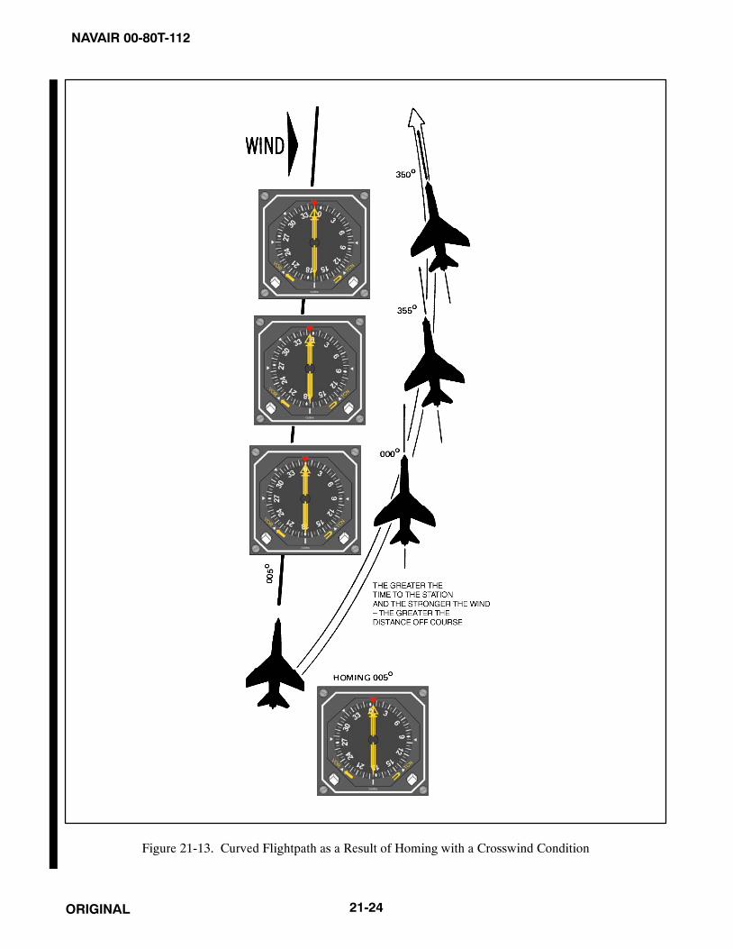
NAVAIR 00-80T-112
ORIGINAL 21-24
Figure 21-13. Curved Flightpath as a Result of Homing with a Crosswind Condition

NAVAIR 00-80T-112
ORIGINAL21-25
DISTANCE CHECK CAN BEMADE WITH HSI USINGTHE SAME TECHNIQUE.
WHEN CDI CENTERS, STOP TIMEAND COMPUTE TIME-DISTANCEFROM THE STATION.
WHEN CDI DISPLACESFROM CENTER POSITION,SET 10� BEARINGCHANGE INTO COURSESELECTOR WINDOW.(CHECK THAT CDI HASMOVED OVER THEHEADING POINTER.)
TURN TO PLACE THE BEARING POINTERON THE NEAREST 90� INDEX.
AFTER COMPLETING TURN, CENTER THE CDI BYSETTING THE BEARING TO THE STATION INTOTHE COURSE SELECTOR WINDOW, NOTE TIME.
A
B
C
D
Figure 21-14. Time — Distance Check

NAVAIR 00-80T-112
ORIGINAL 21-26
Figure 21-15. Bow-to-Beam Bearing Time/Distance Check
Figure 21-16. Double-the-Angle-on-Bow Time/Distance Check

NAVAIR 00-80T-112
ORIGINAL21-27
21.3.12 Holding
(Figures 21-18, 21-19, 21-20, 21-21, 21-22, 21-23, and 21-24.)
1. When holding at a VOR station, pilots should begin the turn to the outbound leg at the time of the first completereversal of the TO-FROM indicator.
2. Patterns at the most generally used holding fixes are depicted on appropriate charts. Pilots are expected to holdin the pattern depicted unless specifically advised otherwise by Air Traffic Control (ATC).
3. ATC clearance requiring that an aircraft be held at a holding point where the pattern is not depicted will includethe following information:
a. General holding instructions.
(1) The direction to hold from holding point. (The direction to hold with relation to the holding fix will bespecified as one of eight general points of the compass [i.e., north, northeast, east, etc.].)
(2) Holding fix.
(3) On (specified) radial course, magnetic bearing airway number of jet route.
(4) Outbound leg length in nm, if DME is to be used.
(5) Left turns, if nonstandard pattern is to be used.
Figure 21-17. 30° Turn Method of Time/Distance Check

NAVAIR 00-80T-112
ORIGINAL 21-28
Figure 21-18. Typical Procedure on an ILS Outer Marker
Figure 21-19. Typical Procedure at Intersection of Radio Range Courses

NAVAIR 00-80T-112
ORIGINAL21-29
Figure 21-20. Typical Procedure at Intersection of VOR Radials
Figure 21-21. Typical Procedure at DME Fix

NAVAIR 00-80T-112
ORIGINAL 21-30
Figure 21-22. Descriptive Terms
Figure 21-23. Standard Pattern

NAVAIR 00-80T-112
ORIGINAL21-31
When the inbound course is toward the NAVAID andthe fix distance is 10 nm and the leg length is 5 nm,then the end of the outbound leg will be reachedwhen the DME reads 15 nm.
When the inbound course is away from the NAVAIDand the fix distance is 28 nm and the leg length is8 nm, then the end of the outbound leg will be reachedwhen the DME reads 20 nm.
END OUTBOUND LEG
NAVAIDDME FIX20 nm
28 nm
NAVAID
END OUTBOUND LEG
DME FIX15 nm
10 nm
Figure 21-24. DME Holding
(6) Time to expect further clearance.
b. Detailed holding instructions: Same as a (1), (2), and (3) above with following additions to (4) and (5):
(1) or minute(s) if DME is not to be used.
(2) or right turns if standard pattern is to be used.
4. Holding pattern airspace protection is based on the following procedures. They are the only procedures forentry and holding recommended by the Federal Aviation Administration (FAA).
a. Entry procedures.
(1) Descriptive terms.
(2) Airspeed (maximum) — Refer to Flight Information Publications (FLIP) general planning.
(3) Entry.
(a) Parallel Procedure — Parallel holding course, turn left, and return to holding fix or intercept holdingcourse. (Also called left turn.)
(b) Teardrop procedure — Proceed on outbound track of 30_ (or less) to holding course, turn right tointercept holding course.
(c) Direct entry procedure — Turn right and fly the pattern. (Also called right turn.)
NoteText and illustration are standard pattern, turns are opposite for nonstandardpattern.

NAVAIR 00-80T-112
ORIGINAL 21-32
(4) Timing.
NoteThe initial outbound leg should be flown for 1 minute or 1-1/2 minutes(appropriate to altitude). Timing for subsequent outbound legs should beadjusted as necessary to achieve proper inbound leg time.
(a) Outbound timing begins over or abeam the fix, whichever occurs later. If the abeam position cannotbe determined, start timing when turn to outbound is completed.
(5) Distance Measuring Equipment (DME).
(a) DME holding is subject to the same entry and holding procedures except that distances (nm) are usedin lieu of time values. The outbound course of a DME holding pattern is called the outbound leg ofthe pattern. The length of the outbound leg will be specified by the controller. The end of theoutbound leg is determined by the DME reading.
(6) Pilot action.
(a) Cross holding fix initially at or below maximum holding airspeed. Effect speed reduction within 3minutes prior to estimated initial time over the holding fix.
(b) Make all turns during entry and while holding at: (1) 3� per second, (2) 30� bank angle, or (3) 25�bank angle (provided a flight director system is used), whichever requires the least bank angle.
(c) Compensate for known effect of wind, except when turning.
(d) Determine entry turn from aircraft heading upon arrival at the holding fix. Plus or minus 5� inheading is considered to be within allowable good operating limits for determining entry.
(e) Advise ATC immediately if any increased airspeed is necessary due to turbulence, icing, etc., or ifunable to accomplish any part of the holding procedures. After such higher speeds are no longernecessary, operate according to the appropriate published holding speed and notify ATC.
NoteAirspace protection for turbulent air holding is based on a maximum of 280Knots Indicated Airspeed (KIAS) or Mach 0.8, whichever is lower.Considerable impact on traffic flow will result when turbulent air holdingpatterns are used; thus, pilot discretion will ensure their use is limited tobona fide conditions/requirements.
(7) Nonstandard holding pattern — Fix end and outbound end turns are made to the left. Entry proceduresto a nonstandard pattern are oriented in relation to the 70� line on the holding side just as in the standardpattern.
5. When holding at a fix, and instructions are received specifying the time of departure from the fix, the pilotshould adjust the flightpath within the limits of the established holding pattern in order to leave the fix at theexact time specified. After departing the holding fix, normal speed is to be resumed with respect to othergoverning speed requirements, such as terminal area speed limits, specific ATC requests, etc. Where the fixis associated with an instrument approach, and timed approaches are in effect, a procedure turn shall not beexecuted unless the pilot advises ATC, as aircraft holding is expected to proceed inbound on final approachdirectly from the holding pattern when approach clearance is received.
NAVAIR 00-80T-112
ORIGINAL21-33
6. Radar surveillance of outer fix holding pattern airspace areas.
a. Whenever aircraft are holding at an outer fix, ATC will usually provide radar surveillance of the outer fixholding pattern airspace area, or any portion of it, if it is shown on the controller’s radarscope.
b. The controller will attempt to detect any holding aircraft that stray outside the holding pattern airspace areaand will assist any detected aircraft to return to the assigned airspace area.
c. Many factors could prevent ATC from providing this additional service, such as workload, number oftargets, precipitation, ground clutter, and radar system capability. These circumstances may make itunfeasible to maintain radar identification of aircraft or to detect aircraft straying from the holding pattern.The provision of this service depends entirely upon whether the controller believes to be in a position toprovide it and does not relieve a pilot of the pilot’s responsibility to adhere to an accepted ATC clearance.
21.3.12.1 Wind Correction Techniques
21.3.12.1.1 Crosswind Correction
After entering the holding pattern, the pilot should compensate for wind in order to arrive at an outbound positionfrom which a turn inbound will place the aircraft on the holding course.
This is normally accomplished by utilizing a larger drift correction on the outbound leg.
21.3.12.1.2 Headwind or Tailwind Corrections
After completing the first circuit of the holding pattern, adjust the time outbound as necessary to provide the desiredinbound time. For example, if the inbound leg was 30 seconds too long, subtract 30 seconds from the outbound leg.In extreme wind conditions, even though the turn inbound is initiated when abeam the station, the inbound leg mayexceed the 1 or 1-1/2 minute limit. In this case only is the pilot authorized to exceed the time limit inbound.
21.3.12.1.3 Meeting an Expected Further Clearance Time (EFC)
The holding pattern may be shortened (never lengthened) as required to meet the Expected Further Clearance Time(EFC). Planning to meet the EFC should be based on the point of departure from the holding pattern. Two factors toconsider in planning are the length of time required to make the two turns and the inbound leg time compared to theoutbound leg.
21.3.12.2 Approaches
A limited number of VOR instrument approaches utilizing a VORTAC facility have been approved for use forTACAN equipped aircraft. These procedures are identified by the phrase “or TACAN” printed adjacent to the nameof the procedure (e.g., VOR or TACAN Rwy 17). Approaches designated as VORTAC may be executed by aircraftusing either TACAN or VOR with DME; DME is required. Approaches designated VOR/DME shall be executed byaircraft utilizing VOR with DME, and both the VOR and DME are required.
The approach procedures discussed in this section are for basic instructiononly. Consult the latest Aeronautical Information Manual/Federal AviationRegulation (AIM/FAR) for detailed procedures.
21.3.12.3 Transition to the Initial Approach Fix (IAF)
Published routes on the terminal chart provide a course and distance from the en route structure to the Initial ApproachFix (IAF). If other than a published routing is used, ensure it does not exceed the operational limitation of theNavigation Aid (NAVAID). Limitations according to type NAVAID, aircraft altitude, and range from the facility arepublished in FLIP.

NAVAIR 00-80T-112
ORIGINAL 21-34
Before reaching the IAF, review the approach chart, recheck the weather at destination and alternate, and obtainclearance for the approach.
An IAF may be approached from directions not favorable to intercepting the initial approach course upon arrival atthe fix. When this occurs, and prior approach clearance has been received, the pilot must maneuver to intercept theinitial approach course. Preapproach intercept maneuvers should be accomplished as follows:
1. Turn at the IAF in the shortest direction to intercept the initial approach course.
2. Begin descent from the Initial Penetration Altitude (IPA) when established on a segment of the publishedapproach.
3. If holding is not required, reduce to penetration airspeed or below before crossing the IAF.
21.3.12.4 High-Altitude Approach Procedures
21.3.12.4.1 Non-DME Teardrop Approach
After crossing the IAF, turn in the shorter direction toward the penetration course. Set the altimeter in accordance withFLIP procedures. Start descent when the aircraft is over or abeam the fix, headed in the direction of the penetrationcourse. Correct to course using “immediately after station passage interception” procedures described inparagraph 21.3.4. Some penetrations include altitude restrictions for a specified number of miles. In these cases,intercept the outbound course and descend as depicted on the approach chart. Before reaching the penetration turnaltitude, set the inbound course in the course selector window. Recheck the altimeter and the minimum altitude forcompletion of the penetration turn.
Perform the penetration turn as published. If it appears the course will not be intercepted upon completion of thepenetration turn, roll out with an intercept to the inbound course. Normally, a 30� to 45� intercept angle is sufficient;however, vary the angle as necessary depending upon groundspeed, displacement from course, and range from thestation.
Descend from the altitude specified for completion of penetration turn when on the inbound course. Before reachingthe Final Approach Fix (FAF), configure the aircraft for landing in accordance with the flight manual. Cross the FAFat the published altitude, start timing, intercept the final approach course, and report to the controlling agency.
NoteThe time-distance tables published in the approach charts are based ongroundspeed; therefore, TAS and the existing wind must be considered inorder to accurately determine the time from the final approach fix to themissed approach point.
Descend to the Minimum Descent Altitude (MDA) so that visual references for landing may be acquired as soon aspractical. Comply with any published altitude restrictions between the final approach fix and Missed Approach Point(MAP). The descent to the MDA should be completed before reaching the missed approach point. Descent belowMDA is authorized when visual reference with the runway environment is sufficient to complete the landing. PartVII discusses landing from a straight-in or circling approach.
The MDA should not be confused with the weather minimums for the approach being flown. The weather minimumsindicate the ceiling and visibility required before the approach may be started (reference OPNAV 3710.7 series,Chapter 5, Approach Criteria for Multipiloted Aircraft). The MDA indicates the minimum altitude Mean Sea Level(MSL) to which the aircraft may be flown. Use Runway Visual Range (RVR) for the visibility minimum whenavailable. The RVR is found in the landing minimums block next to the MDA (Figure 21-25).

NAVAIR 00-80T-112
ORIGINAL21-35
Figure 21-25. VOR Non-DME Teardrop High-Altitude Approach

NAVAIR 00-80T-112
ORIGINAL 21-36
Perform the missed approach when:
1. Visual reference with the runway environment at the missed approach point is insufficient to complete thelanding.
2. Instructed by the controlling agency.
3. A safe landing is not possible.
21.3.12.4.2 Dual-Facility Approaches
This type of approach may use dual VOR, ADF, or a combination of the two facilities. Figure 21-26 illustrates onetype of dual-facility approach. With dual navigational receivers, this type of approach offers a few advantages overthe non-DME teardrop approach. The pilot can maintain course on one facility and monitor his progress by referenceto the second facility. Normally, the distance between the IAF and FAF is published in the profile view of the approachchart. If the pilot is position oriented, the pilot can better approximate the time available to configure the aircraft forthe final approach.
With only a single VOR (or ADF) receiver, this type of approach may require a high degree of pilot proficiency. Inthe illustration, a pilot flying this approach would have to retune the VOR several times in order to intercept andmaintain course and, at the same time, determine the aircraft position in relation to the intersection(s). Considerweather, aircraft equipment, and pilot proficiency when planning a dual-facility approach.
NoteDual receivers are required when an intersection (formed by a radial fromanother facility) is used as a step-down fix between the final approach fixand missed approach point.
21.3.12.5 Low-Altitude Approach Procedures
The reduction of airspace and the predominant use of the procedure turn are two factors that distinguish the Low- (AL)from the High-Altitude Approach (JAL). Pilots of high-performance aircraft that have an operational requirementto use the low-altitude charts (AL) should maneuver at airspeeds compatible with the depicted procedure. CategoryE will be depicted on low-altitude (AL) procedures only where an operational requirement exists. Procedure turnsare discussed under paragraph 21.3.12.6. Some low-altitude VOR (or ADF) approaches do not use the procedure turn(Figure 21-27). The guidance concerning transition found preceding high-altitude approach procedures also appliesto low-altitude approach procedures.
21.3.12.5.1 Straight-In Approaches
A straight-in approach is an instrument approach conducted by proceeding over the FAF at the prescribed altitude andcontinuing inbound on the final approach course to the airport without making a Procedure Turn (PT). When issueda clearance for a straight-in approach while conducting a timed approach from a holding fix, when the initial approachpublished on the Instrument Approach Procedure (IAP) is designated NoPT (procedure turn not required), or whenATC radar vectors to a final approach position are provided, the pilot shall not make a procedure turn unless the pilotso advises ATC and an appropriate clearance is received. Some instrument approach procedures specifically prohibituse of a procedure turn (Figure 21-27).
An aircraft cleared to a holding fix, other than the IAF, then subsequently cleared for a straight-in approach (even ifthe aircraft has not yet entered holding) is expected by ATC to proceed to the IAF via the holding fix to commencethe approach. If route of flight directly to the IAF is desired, it should be so stated by the controller. If doubt exists,contact ATC to determine the correct route of flight.

NAVAIR 00-80T-112
ORIGINAL21-37
Figure 21-26. Dual VOR High-Altitude Approach

NAVAIR 00-80T-112
ORIGINAL 21-38
Figure 21-27. VOR Low-Altitude Straight-in Approach

NAVAIR 00-80T-112
ORIGINAL21-39
When operating on an unpublished route or while being radar vectored when an approach clearance is received, thepilot shall maintain the last assigned altitude: unless a different altitude is assigned by ATC or until the aircraft isestablished on a segment of a published route or instrument approach procedure. Descend from the initial approachaltitude to the next altitude depicted after established on the initial approach course. If there is insufficient time tointercept course and comply with the first altitude restriction, before starting the approach, request ATC clearanceto maneuver for a favorable alignment with the initial approach course. Before reaching the FAF, configure the aircraftfor landing in accordance with the applicable NATOPS flight manual. At the FAF, start the time, intercept the finalapproach course, and call the controlling agency, if required.
If no FAF is depicted, treat the point of interception of the final approach course as the FAF.
NoteThe time-distance tables published in the approach charts are based ongroundspeed; therefore, TAS and the existing wind must be considered todetermine accurately the time from the final approach fix to the missedapproach point.
Descend to the MDA so that visual references for landing may be acquired as soon as practical. Comply with anypublished altitude restriction between the FAF and missed approach point. Descent below MDA is authorized whenvisual reference with the runway environment is sufficient to complete the landing. Perform the missed approachwhen:
1. Visual reference with the runway environment at the missed approach point is insufficient to complete thelanding.
2. Instructed by the controlling agency.
3. A safe landing is not possible.
21.3.12.6 Procedure Turns (PT)
A Procedure Turn (PT) is a maneuver that is designed to place the aircraft on an inbound course to the FAF. Further,it provides for descent to the FAF altitude and affords the pilot time to establish the final approach configuration. Aprocedure turn is normally associated with the low-altitude approach (AL); however, it may be included as a part ofthe High-Altitude Approach (JAL) procedure (Figures 21-28 and 21-29).
21.3.12.6.1 Entry
Initial entry for a procedure turn may be accomplished as described under paragraph 21.3.12, or may be made by theaircraft turning in the shortest direction to proceed outbound. On U.S. Government charts, a barbed arrow indicatesthe direction or side of the outbound course on which procedure turn is made. Headings are provided for coursereversal using the 45 degree type procedure turn; however, the point at which the turn may be commenced and thetype and rate of turn is left to the discretion of the aircrew. Some of the options are the 45 degree procedure turn, theracetrack pattern, the teardrop procedure turn, or the 80/260 degree course reversal. Some procedure turns arespecified by procedural track. These turns must be flown exactly as depicted.
When the approach procedure involves a procedure turn, a maximum speed of not greater than 200 knots IndicatedAirspeed (IAS) should be observed from first overheading the course reversal IAF through the procedure turnmaneuver to ensure containment within the obstruction clearance area.

NAVAIR 00-80T-112
ORIGINAL 21-40
Note
COMMENCE PROCEDURE TURN.
Figure 21-28. VOR Low-Altitude Approach, Procedure Turn Type

NAVAIR 00-80T-112
ORIGINAL21-41
Note
Figure 21-29. VOR Low-Altitude Approach, Teardrop Required

NAVAIR 00-80T-112
ORIGINAL 21-42
On the outbound leg, the aircraft shall not exceed the protected airspace depicted. At the completion of the outboundleg, course reversal may be accomplished by utilizing the 90-270 method, the depicted procedure turn headings, orany other method that safely reverses course and keeps the aircraft on the Procedure Turn (PT) side of the approachcourse within the protected airspace. If on a teardrop approach, at the completion of outbound timing, turn in theshortest direction toward the inbound course.
When nonstandard distances are specified, adjust timing in order to comply with the depicted procedure. The standardprocedure turn length is 10 nm (15 nm on terminal charts where Category E minimums are published). For thoseprocedure turns prescribed from a DME fix, adhere to published distance restrictions in lieu of timing.
21.3.12.6.2 Descent
Initiate descent from the initial approach altitude to the published procedure turn altitude when the aircraft is abeamthe fix or wings level outbound, whichever occurs last. Start descent from procedure turn altitude to final approachfix altitude when the aircraft is headed inbound on the inbound course. If a teardrop is performed from a fix withoutoutbound course guidance, descend from procedure turn altitude when the aircraft is on course inbound.
Before reaching the final approach fix, configure the aircraft for landing in accordance with the NATOPS flightmanual. At the final approach fix, note the time, make the mandatory position report, and intercept the final approachcourse to the airfield. If no FAF is depicted, treat the point at which the aircraft has intercepted the inbound courseas the FAF.
NoteThe time-distance tables published on the approach charts are based ongroundspeed; therefore, TAS and the existing wind must be considered inorder to determine accurately the time from the final approach fix to themissed approach point.
Descend to the MDA so that visual references for landing may be acquired as soon as practical. Comply with anypublished altitude restriction between the FAF and missed approach point. Descent below MDA is authorized whenvisual reference with the runway environment is sufficient to complete the landing and the Visual Descent Point(VDP) has been reached.
Perform the missed approach when:
1. Visual reference with the runway environment at the missed approach point is insufficient to complete thelanding.
2. Instructed by the controlling agency.
3. A safe landing is not possible.
21.3.12.7 Approaches from Holding
21.3.12.7.1 Holding Type Approach
When executing an approach that specifies a holding pattern in lieu of a procedure turn, the pilot must fly the holdingpattern and does not retain the option of executing a procedure turn or teardrop (Figure 21-30). When established inholding and cleared for the approach, the pilot may start the descent from any position in the pattern. The aircraft willbe configured for landing prior to reaching the FAF.
21.3.12.7.2 Holding Pattern Located on the Initial Approach Course
When cleared to hold in a pattern depicted on the approach plate on the initial approach course, and subsequentlycleared for the approach, the pilot may depart holding from any position and need not return to the holding fix. Pilotsmay intercept the teardrop or procedure turn course directly and commence descent from IAF altitude immediately.They may also remain in the holding pattern to dissipate excessive altitude power to proceeding outbound on theprocedure turn or teardrop course (Figure 21-29).

NAVAIR 00-80T-112
ORIGINAL21-43/(21-44 blank)
Note
ATC MAY RADAR VECTOR AN AIRCRAFT FORA STRAIGHT-IN VERSION OF THIS APPROACH.NORMALLY, THIS WOULD BE VIA THE CRP 138RADIAL INBOUND TO THE FAF.
START TIME FORHOLDING PATTERN. SETINBOUND COURSE INSELECTOR WINDOW.
EXECUTE MISSEDAPPROACH IF NECESSARY.
NOTE TIME. INTERCEPT FINALAPPROACH COURSE. CALLCONTROLLING AGENCY.DESCEND TO MINIMUM DESCENTALTITUDE.
COMMENCE TURN TOOUTBOUND HEADING.
CALL CONTROLLINGAGENCY. BEGINDESCENT.MAINTAIN MINIMUM
DEPICTED HOLDINGPATTERN ALTITUDE.
REDUCE TO MANEUVERINGAIRSPEED. OBTAIN APPROACHCLEARANCE.
TURN TO INTERCEPTINBOUND COURSE.
Figure 21-30. VOR Low-Altitude Approach, Holding Type

NAVAIR 00-80T-112
ORIGINAL21-1/(21-2 blank)
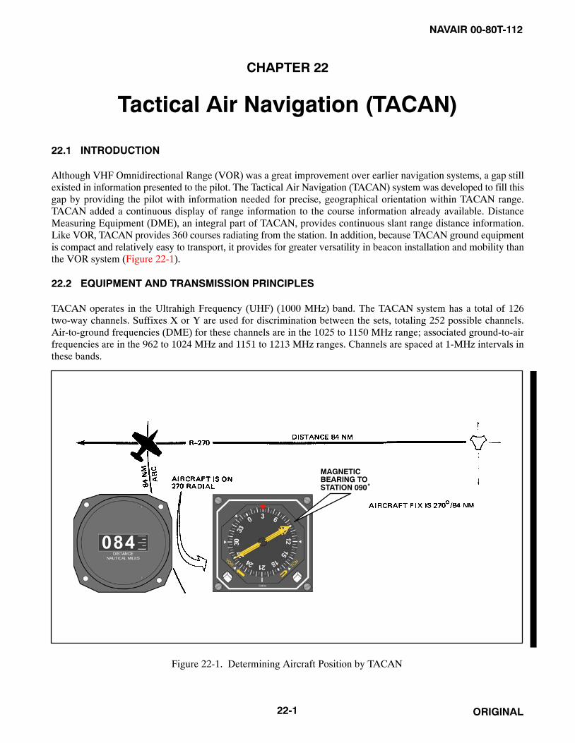
NAVAIR 00-80T-112
ORIGINAL22-1
CHAPTER 22
Tactical Air Navigation (TACAN)
22.1 INTRODUCTION
Although VHF Omnidirectional Range (VOR) was a great improvement over earlier navigation systems, a gap stillexisted in information presented to the pilot. The Tactical Air Navigation (TACAN) system was developed to fill thisgap by providing the pilot with information needed for precise, geographical orientation within TACAN range.TACAN added a continuous display of range information to the course information already available. DistanceMeasuring Equipment (DME), an integral part of TACAN, provides continuous slant range distance information.Like VOR, TACAN provides 360 courses radiating from the station. In addition, because TACAN ground equipmentis compact and relatively easy to transport, it provides for greater versatility in beacon installation and mobility thanthe VOR system (Figure 22-1).
22.2 EQUIPMENT AND TRANSMISSION PRINCIPLES
TACAN operates in the Ultrahigh Frequency (UHF) (1000 MHz) band. The TACAN system has a total of 126two-way channels. Suffixes X or Y are used for discrimination between the sets, totaling 252 possible channels.Air-to-ground frequencies (DME) for these channels are in the 1025 to 1150 MHz range; associated ground-to-airfrequencies are in the 962 to 1024 MHz and 1151 to 1213 MHz ranges. Channels are spaced at 1-MHz intervals inthese bands.
MAGNETICBEARING TOSTATION 090°
Figure 22-1. Determining Aircraft Position by TACAN

NAVAIR 00-80T-112
ORIGINAL 22-2
22.2.1 Ground Equipment
The ground equipment consists of a rotating type antenna for transmitting bearing information and areceiver-transmitter (transponder) for transmitting distance information. The TACAN identifies itself aurally throughinternational Morse code every 35 seconds. Permanent TACAN ground stations are usually dual-transmitter equipped(one operating and one on standby), fully monitored installations that automatically switch to the standby transmitterwhen a malfunction occurs. The ground monitor (set to alarm at any radial shift of ±1�) is usually located in the basecontrol tower or approach control and sets off a light and buzzer to warn the groundcrew when an out-of-tolerancecondition exists. Anytime TACAN reception is suspected or bearing/distance unlock conditions are encountered inflight, a pilot can check on the status of the ground equipment by calling Air Traffic Control (ATC). When groundequipment is undergoing repairs that might cause it to transmit erroneous signals, its identification must be silenced;therefore, always listen for identification signals during flight (Figure 22-2).
22.2.1.1 TACAN Signal Pattern
The signal pattern for bearing information is formed by varying the nondirectional pattern sent from the stationarycentral element of the antenna. This is done by rotating a cylinder around the central element of the antenna at15 revolutions per second (rps) (Figure 22-3, part A). A metal wire embedded vertically in the plastic cylinder distortsthe radiated signal into a cardioid (heart-shaped) pattern, and its rotation causes the cardioid pattern to also revolveat 15 rps. This resulting rotating pattern is referred to as the course pattern. From this, the aircraft receives a 15cycles-per-second (cps) amplitude modulation. This means that the strength of the signal goes from maximum tominimum and back to a maximum at the rate of 15 cps.
Another larger cylinder, with nine wires in it, is mounted around the central element and the smaller cylinder and alsorotates at 15 rps. This is the fine antenna that superimposes nine lobes on the already-formed course pattern. Thisforms a 135 cps signal (Figure 22-3, part B).
Figure 22-2. TACAN Ground Beacon Antenna

NAVAIR 00-80T-112
ORIGINAL22-3
Figure 22-3. TACAN Antenna Pattern
To determine the aircraft position in bearing from the station, a phase angle must be measured electronically. Tomeasure the phase angle, a fixed reference is established. This fixed reference is a 15-cps nondirectional pulse signalnormally referred to as the main reference bearing pulse. One main reference pulse occurs with each revolution ofthe antenna. In addition to the main reference pulse, eight auxiliary reference pulses also occur during one revolutionof the ground beacon antenna; therefore, a reference pulse occurs each 40� of antenna rotation (360� = 9 pulses).
The airborne equipment electronically measures the time lapse between the main reference pulse and the maximumamplitude (signal strength) of the 15-cps rotating signal pattern. This determines the aircraft bearing from the stationwithin a 40� sector. Then, the time lapse between the auxiliary reference pulses and the maximum amplitude of the135-cps signal is measured to determine the aircraft position within the 40� sector. The accuracy of this measurementdetermines the position of the aircraft relative to the station within ±1� (Figure 22-4).
22.2.1.2 Distance Measuring Equipment (DME)
Distance is determined with TACAN equipment by measuring the elapsed time between transmission of interrogatingpulses of the airborne set and reception of corresponding reply pulses of the ground station. The aircraft transmitterstarts the process by sending out the distance interrogation pulse signals. Receipt of these signals by the ground stationreceiver triggers its transmitter, which sends out the distance reply pulse signals. These pulses require approximately12 microseconds round trip travel time per nm of distance from the ground beacon. The range indicator displaysdistance to the TACAN beacon in nm (Figure 22-5).

NAVAIR 00-80T-112
ORIGINAL 22-4
Figure 22-4. Combined Course and Fine Bearing Signals
Figure 22-5. Interrogation and Reply Pulses for DME

NAVAIR 00-80T-112
ORIGINAL22-5
As a large number of aircraft could be interrogating the same beacon, the airborne set must sort out only the pulsesthat are replies to its own interrogations. Interrogation pulses are transmitted on an irregular, random basis by theairborne set, which then searches for replies synchronized to its own interrogations. If the signals are interrupted, amemory circuit maintains the last distance indication on the range indicator for approximately 10 seconds to preventthe search operation from recurring. The searching process starts automatically whenever the airborne set is tunedto a new beacon or when there is a major interruption in beacon signals. Depending upon the aircraft actual distancefrom the beacon at the time, the searching process may require up to 22 seconds (Figure 22-6).
22.2.2 TACAN Characteristics
22.2.2.1 Bearing/Distance Unlock
TACAN bearing and distance signals are subject to line-of-sight restrictions. Because of the transmission/receptionprinciples, unlock (rotating of bearing pointer and/or range indicator) will occur if these signals are obstructed.Temporary obstruction of TACAN signals can occur in flight when aircraft fuselage, wing, gear, external stores, orwingmen get between the ground and aircraft antenna. Aircraft receiver memory circuits prevent unlock when signalsare obstructed for short periods (approximately 10 seconds for DME and 2 seconds for azimuth), but beyond this,unlock occurs and will persist until the obstruction is removed and search cycles are completed. Unlock may occurduring procedure or penetration turns, or during maneuvers that cause the aircraft antenna to be obstructed for longerthan 2 to 10 seconds.
Figure 22-6. Slant Range Distance
NAVAIR 00-80T-112
ORIGINAL 22-6
22.2.2.2 Azimuth Cone of Confusion
The structure of the cone of confusion over a TACAN station is considerably different from other navigational aids.The azimuth cone can be up to 100� or more in width (approximately 15 nm wide at 40,000 feet). Indications on theaircraft instruments make it appear even wider to the pilot. Approaching the TACAN station, usable azimuthinformation is lost before the actual cone is reached, although actual azimuth unlock is prevented by the memorycircuit until after the aircraft is into the cone. After the cone is crossed and usable signals are regained, the search cyclefunction (22 seconds for a full cycle) prior to regaining lock-on extends the unusable area beyond the actual cone.
22.2.2.3 DME Cone of Confusion
The DME cone is much narrower and is actually insignificant to TACAN operation as DME unlock should neveroccur when crossing the station except for hovering or very slow aircraft. Faster aircraft should get through the DMEcone area regardless of altitude before unlock occurs. On crossing a TACAN station, the DME should decrease untilthe center of the cone is reached, stop, then begin to show an increase as the signal is regained.
22.2.2.4 Range Indicator Fluctuations
Slight oscillations up to approximately 1/4 nm are normal for range indicator operation due to the pulses generatedby the transmit/receive function. When a usable signal is lost, the memory circuit maintains the indicated range forapproximately 10 seconds, after which unlock will occur unless usable signals are regained.
22.2.2.5 Erroneous TACAN Indications
Several forms of malfunction of airborne equipment or interference between ground stations can give false orerroneous TACAN information to a pilot. These discrepancies are easier to recognize and guard against if the pilotis aware they can occur.
22.2.2.5.1 40� Azimuth Error Lock-On
As previously explained, the construction of the TACAN ground antenna is such that it transmits a series of nine signallobes (eight auxiliary and one main reference pulse) 40� apart. With the airborne receiver working correctly, thesepulses lock on the airborne equipment with the main reference at 90�. With a weak airborne receiver, the mainreference pulse may slide over or miss the 90� slot and lock on at one of the auxiliary positions. When this occurs,azimuth indications will be 40� or some multiple of 40� in error. Rechanneling the airborne receiver to deliberatelycause unlock gives the set another chance to lock on properly. When VOR or ADF bearing information is available,use it to verify the existence of suspected TACAN errors.
22.2.2.5.2 Adjacent Channel Interference
Adjacent channel interference occurs when an aircraft is in a position to receive TACAN signals from more than oneground station on the same frequency. Normally, this occurs only at high altitudes when distance separation betweenlike frequencies is inadequate. DME, azimuth, or identification from either ground station may be received. This isnot a malfunction of either air or ground equipment, but a result of ground equipment location and aircraft position.
22.2.2.5.3 False or Incorrect Lock-On
False or incorrect lock-on indications in the aircraft can be caused by misalignment or excessive wear of the airbornecrystal selector assembly. Selection of a numbered TACAN channel activates a drum and wiper arrangement in theaircraft black box, which rotates until the wiper contacts the proper crystal on the drum. These crystal contact pointsare very small (pinhead size) and close together. Wear of this assembly or misalignment can cause the wiper to missthe proper crystal and contact the wrong one, resulting in the wrong TACAN being tuned in, or the wiper can misscontact entirely, resulting in constant unlock. When this occurs, rechanneling from the selected channel number andback (preferably from the opposite direction than the original setting) sometimes results in proper channelization.This is an airborne equipment malfunction.

NAVAIR 00-80T-112
ORIGINAL22-7
22.2.2.5.4 Precautionary Actions
Several precautionary actions should be taken by pilots to guard against in-flight use of erroneous navigation signals:
1. Always check the identification of any navigational aid station and monitor it during flight. Always utilize allsuitable navigation equipment aboard the aircraft and cross-check heading and bearing information.
2. Never overfly preplanned Estimated Times of Arrival (ETAs) without careful cross-check of navigational aidsand ground checkpoints.
3. Check Notices to Airmen (NOTAMs) and Flight Information Publications (FLIP) before flight for possiblemalfunctions or limitations on navigational aids to be used.
4. Discontinue use of any suspected navigational aid and, if necessary, confirm aircraft position with radar orother equipment.
NoteIf there is a malfunction of the compass system or card, consider theTACAN bearing information unreliable and merely advisory until verifiedby radar or other navigational equipment.
22.2.3 TACAN Procedures
As TACAN presents bearing information in the same manner as VOR, use the same homing, proceeding direct, courseinterception, and maintaining course procedures explained in Part 1 (VOR Navigation); however, with the additionof range information, additional procedures have been devised to use TACAN to its full advantage. The remainderof this chapter is devoted to those procedures that differ from VOR.
22.2.3.1 Tuning
The TACAN control panel (Figure 22-7) consists of a power switch, volume control, and channel selector. The powerswitch has four positions: OFF, REC, T/R, and A/A. Selecting either the REC or T/R position turns on the set. (Assome TACAN sets require a warmup period in the REC position, before selecting the T/R position, refer to theappropriate aircraft flight manual for instructions.) In the REC position, only bearing information and stationidentification are available. In the T/R position, bearing/distance information and station identification are available.After turning on the equipment, select the desired channel, adjust the volume, and identify the station. Afteridentifying the TACAN station, an unreliable signal can be identified on the instrument (refer to specific aircraftNATOPS).
Tune and check the set before takeoff. After tuning, check the bearing pointer, Course Deviation Indicator/HorizontalSituation Indicator (CDI/HSI) TO-FROM indicator, and range indicator for proper operation. The bearing pointershould point to magnetic bearing to the station. The CDI/HSI should center when this bearing is set in the courseselector window, and the TO-FROM indicator should indicate TO. The range indicator should indicate the distanceto the station.
22.2.3.2 Groundspeed Check
A groundspeed check can be made while maintaining a course to or from a TACAN station; however, as a guide,groundspeed checks should be performed only when the aircraft slant range distance is more than the aircraft altitudedivided by 1,000. For example, if the aircraft is at Flight Level (FL) 200, groundspeed checks should be performedwhen beyond 20 nm. Checks made below 5,000 feet are accurate at any distance.

NAVAIR 00-80T-112
ORIGINAL 22-8
1. VOLUME CONTROL2. CHANNEL DISPLAY3. POWER SWITCH4. X/Y CHANNEL SELECTOR SWITCH5. RIGHT KNOB SELECTS UNITS DIGITS6. LEFT KNOB SELECTS 100 AND 10 DIGITS7. AIR-TO-AIR (A/A)/AIR-TO-GROUND (A/G) SELECTOR SWITCH
1 2 3
4567
Figure 22-7. TACAN Control Panel
To perform the groundspeed check, begin timing when the range indicator shows a whole number. After thepredetermined time has elapsed, check the range indicator and note the distance flown. Apply this information to thefollowing formula to determine groundspeed:
Distance flown � 60 = Groundspeed elapsed time in minutes.
For precise computation, time for longer periods and solve the problem on a computer. To simplify computations,use a 2-minute time check and multiply the distance traveled by 30; for a 3-minute time check, multiply distance by20; for a 6-minute time check, multiply distance by 10 (Figure 22-8).
22.2.3.3 Station Passage
Because of the azimuth cone of confusion over the TACAN station, station passage is determined when the rangeindicator stops decreasing. Flying directly over the station, the range indicator will stop decreasing when it indicatesthe approximate aircraft altitude above the station in nm. One nm is equal to approximately 6,000 feet. For example,an aircraft cruising at FL 300 is at an altitude of approximately 5 nm; therefore, the range indicator should stopdecreasing at approximately 5 nm when directly over a station at sea level. If the station elevation is 6,000 feet, theindicated range over the station would be approximately 4 nm (Figure 22-9).
22.2.3.4 TACAN Arcs
Sometimes used during approaches and departures, a TACAN arc is flown around the station at a specific distance.Some approaches require the entire final approach to be flown along an arc, using radials to determine the FinalApproach Fix (FAF) and the Missed Approach Point (MAP). On the other hand, an arc may be used to transition tothe FAF and the MAP. During departures, it may be necessary to fly an arc soon after takeoff to transition to a departureradial. Arc instructions are given as “VIA (NUMBER OF MILES) MILE ARC (DIRECTION) OF (NAME OFNAVAID).” Direction will be given as “ARC SOUTH” or “ARC EAST,” etc.

NAVAIR 00-80T-112
ORIGINAL22-9
Figure 22-8. Groundspeed Check
Figure 22-9. Indication of Station Passage

NAVAIR 00-80T-112
ORIGINAL 22-10
22.2.3.5 Arc Interceptions
To intercept an arc from a radial, a turn of approximately 90� is required to place the bearing pointer on the wingtipwith a range indication equal to the desired arc. Determine the direction to turn and the desired lead point. Lead pointwill equal 0.5 percent of groundspeed (200 knots � .005 = 1 nm). Rollout heading is based on determining if theaircraft is inside or outside of desired arc track. Detailed techniques for correcting to the arc are discussed underparagraph 22.2.3.6.
22.2.3.5.1 Techniques for Determining Lead
When using 30� of bank, an approximate lead point for the arc may be determined from the aircraft Groundspeed(GS) or Mach. Groundspeed in nm per minute minus 2 represents the approximate lead (e.g., 6 nm per minute, use4 nm lead). A Mach indicator may be used in the same manner to determine a no-wind lead point because 0.5 Machis approximately 5 nm per minute, 0.6 Mach is 6 nm per minute, etc. Lead points based on aircraft turn radius maybe approximated as follows: 1 percent � GS = nm lead for 1-1/2� per second rate of turn, 1/2 percent � GS = nmlead for 3� per second rate of turn. For groundspeeds below 150 knots, 1/2 nm lead point is satisfactory (Figure 22-10).
22.2.3.6 Maintaining Arcs
In theory, it is a simple matter to maintain an arc. Under no-wind conditions, the aircraft will fly in an exact circlearound the station by maintaining a relative bearing of 90� or 270�. In practice, a method for maintaining an arc isto fly a series of short legs, keeping the bearing pointer on or near the wingtip position while maintaining the desiredrange. With the bearing pointer on the wingtip and the aircraft at the desired range, maintain heading and allow thebearing pointer to move 5� to 10� behind the wingtip position. This will cause the range to increase slightly. Next,turn toward the station to place the bearing pointer 5� to 10� ahead of the wingtip, and maintain this heading untilthe bearing pointer is again behind the wingtip.
During crosswind conditions, the reference point (wingtip) will change. If the wind is blowing the aircraft away fromthe station, the reference point is ahead of the wingtip. If the wind is blowing the aircraft toward the station, thereference point is behind the wingtip. While proceeding around the arc, the drift correction will constantly bechanging for a constant wind direction and velocity. As a guide, correct approximately 10� to 20� for each 1/2 miledeviation from the desired arc. For example, under no-wind conditions, if the aircraft is 1/2 mile outside the arc andthe bearing pointer is on the wingtip, the aircraft should be turned approximately 20� toward the station to return tothe arc. The actual amount of correction required for a given error varies. Factors to consider are the size of the arc,groundspeed of the aircraft, whether the aircraft is inside or outside of the arc, etc. These variables are seen by thepilot as rates of deviation. Establish a correction according to the rate of deviation and adjust as necessary accordingto the rate of correction. Remember that the curve of small arcs is relatively sharp, and corrections from the insideare assisted by the arc curving toward the aircraft. Conversely, the aircraft outside small arc requires larger correctionsbecause of the curvature away from the aircraft. Large arcs are easier to fly because of their flatter curve. Highgroundspeeds require more pilot attention to maintain an arc because of higher rates of deviation and correction(Figure 22-11).
22.2.3.7 Intercepting a Radial from an Arc
To intercept a radial from an arc, set the desired course in the course selector window as soon as practical. Monitorthe rate of bearing pointer movement while flying the arc, and remember that the interception angle will beapproximately 90�. Changing the lead point used for the arc interception from nautical miles to degrees is a techniquethat can be used to determine an approximate lead point. Use the relationship that 1� is 1 nm wide at 60 nm from thestation and its width increases or decreases in proportion to the distance. For example, with a 200-knot groundspeed(using a 3� per second rate of turn), a 1-nm lead point was used to intercept the 10-nm arc. Because 1� of travel alongthe 10 nm arc represents 1/6 nm, the lead point when intercepting a radial from the arc (no wind) would be 6�(Figure 22-12).

NAVAIR 00-80T-112
ORIGINAL22-11
Figure 22-10. Intercepting an Arc from a Radial

NAVAIR 00-80T-112
ORIGINAL 22-12
Figure 22-11. Correcting to Maintain the Arc

NAVAIR 00-80T-112
ORIGINAL22-13
Figure 22-12. Intercepting a Radial from an Arc (No Wind)
NAVAIR 00-80T-112
ORIGINAL 22-14
22.2.3.8 Technique of Navigating Point to Point
When an aircraft approaches a terminal area, air traffic control normally clears it to the holding fix or the initialapproach fix. This clearance may be to the station and out the radial, along an arc to a radial, or direct to the fix. Ifcleared direct to the fix, the pilot may use a radar vector or point-to-point navigation.
A single TACAN providing bearing and distance information is sufficient for navigating directly to any fix (radialand distance) within reception range of the station.
Basic navigation principles are used and include:
1. Establishing two fixes (aircraft and desired).
2. Connecting the fixes with a line.
3. Reading the heading to the desired fix.
The technique of applying these principles in the aircraft without cumbersome charts is simple. The key to thistechnique is in learning to visually establish the aircraft and the desired fix on the compass card of a Radio MagneticIndicator (RMI) or similar type instrument (Figure 22-13). The following factors will aid in developing this ability:
1. The TACAN station is always at the center of the compass card. The compass card is merely a compass rosearound the station.
2. The fix having the greater distance is always established on its radial at the outer edge of the compass card.
3. The remaining fix is established along its radial at a point whose distance from the center of the card isproportional to the distance represented by the outer edge of the compass card.
For example, assume an aircraft to be on the 180� radial (indicated by the tail of the bearing pointer) at 60 nm. Thepilot desires to proceed direct to a fix located on the 90� radial at 30 nm.
If not proceeding in the general direction of the fix, turn to a heading approximately halfway between the head of thebearing pointer and the desired fix radial, then:
1. Establish the fix with the greater distance (60 nm) on the edge of the card at its radial (180�). The distancerepresented from the center to the edge of the compass card is now 60 nm.
2. Establish the remaining fix (90�/30�) along the 90� radial at a proportionate distance from the center (i.e.,halfway).
3. Connect the two fixes with an imaginary line or with the aid of a pencil or other straight edge. Move the lineto the center of the compass card so that it is parallel to the original line.
4. Read the no-wind heading at the point where the second line crosses the compass card (30�). Always readdirection from the aircraft position to the desired fix. Turn to this heading and apply wind correction.
As the distance from the center to the edge of the compass card represents 60 nm, the diameter of the card providesa 120-nm scale. The distance between the aircraft fix and the desired fix may be determined using this scale(approximately 65 miles in the example). The Estimated Time En Route (ETE) to the desired fix may then bedetermined by applying aircraft groundspeed. For better accuracy, repeat the entire technique occasionally while enroute (Figure 22-14).

NAVAIR 00-80T-112
ORIGINAL22-15
22.2.3.9 TACAN Holding
Holding is maneuvering an aircraft in relation to a navigational fix while awaiting further clearance. Initial entry forTACAN holding is identical to that described earlier for VOR, except a TACAN DME fix is substituted for a VORas the holding fix. The standard no-wind holding pattern is flown by following a specified holding course inboundto the holding fix, making a 180� turn to the right, flying a heading outbound to parallel the holding course, andmaking another 180� turn to the right to intercept and follow the holding course to the fix. The length of the legs whileusing TACAN is usually specified in nautical miles. Pilots should not confuse TACAN holding fix (radial/distance)with the TACAN station when considering the direction of holding. As illustrated in Figure 22-15, the direction ofholding is relative to the 30-nm fix rather than the TACAN station. The direction of turn is not included for standardholding patterns. While in the holding pattern, turns are initiated at the indicated range as published or issued by thecontroller. To meet the expected approach time, the pattern may be shortened, but never lengthened. The inboundcourse to the holding fix should be set in the course selector window. As the holding pattern may be a considerabledistance from the TACAN station, course corrections to intercept course prior to reaching the holding fix will be largerthan those normally used in VOR or ADF holding. For example, 6� off course at 30 miles is a 3-mile course error,whereas 6� off course at 10 miles is only a 1-mile course error.
Figure 22-13. Visualize Problem after Turning to Computed Heading

NAVAIR 00-80T-112
ORIGINAL 22-16
A
B
CA
B
BC
Figure 22-14. The Technique of Proceeding Direct Between TACAN Fixes

NAVAIR 00-80T-112
ORIGINAL22-17
Figure 22-15. The Direction of TACAN Holding is Relative to the Holding Fix, Not the Station

NAVAIR 00-80T-112
ORIGINAL 22-18
22.2.4 TACAN Approach Procedures
With range information available, many different types of penetrations are depicted on the approach charts. SomeTACAN approaches are relatively simple and involve only a straight-in flightpath along a radial. Others requireextensive planning and may involve intercepting an arc from a radial, a radial from an arc, or any combination of theabove to arrive at the final approach fix (Figure 22-16).
A limited number of VOR instrument approaches based on a VORTAC facility have been approved for use byTACAN-equipped aircraft. These procedures are identified by the phrase “or TACAN” printed adjacent to the nameof the procedure (e.g., VOR TACAN Rwy 17). Approaches designated VORTAC may be executed by aircraft usingeither TACAN or VOR with DME, but DME is required. Approaches designated VOR/DME may be executed byaircraft utilizing VOR with DME, and the DME is required.
22.2.4.1 Transition to the Initial Approach Fix
Published routes on the terminal chart may provide a course and range from the en route structure to the InitialApproach Fix (IAF). If a routing other than one published is used, ensure it does not exceed the operational limitationof the Navigation Aid (NAVAID) being used. Limitations according to type NAVAID, aircraft altitude, and range fromthe facility are published in FLIP. Before reaching the IAF, recheck the weather, review the approach chart, and obtainclearance for the approach.
An IAF may be approached from directions not favorable to intercepting the initial approach course upon arrival atthe fix. When this occurs, and prior approach clearance has been received, the pilot must maneuver to intercept theinitial approach course. Preapproach intercept maneuvers should be accomplished as follows:
1. Turn at the IAF in the shortest direction to intercept the initial approach course.
2. Begin descent from the Initial Penetration Altitude (IPA) when established on a segment of the publishedapproach.
3. If holding is not required, reduce to penetration airspeed or below before crossing the IAF.
22.2.4.2 High-Altitude Penetration and Approach
When over the IAF, turn in the shorter direction toward the penetration course. Descent may be started whenestablished on a segment of the published approach. Crossing the arc forming the IAF is considered abeam. Interceptthe initial penetration course and fly the approach as depicted.
At or before reaching the FAF, configure the aircraft for landing in accordance with the NATOPS flight manual. Atthe FAF, report to the controlling agency. Descend to the Minimum Descent Altitude (MDA) to acquire visualreferences for landing as soon as practical. Comply with any published altitude restriction between the FAF andmissed approach point. The descent to the MDA should be completed before reaching the missed approach point.Descent below MDA is authorized when visual reference with the runway environment is sufficient to complete thelanding and the Visual Descent Point (VDP) has been reached.
There are a few approaches that have the final approach course along an arc. On these approaches, the FAF and missedapproach point are designated by radials rather than range.
Perform the missed approach when:
1. Visual reference with the runway environment at the missed approach point is insufficient to complete thelanding.
2. Instructed by the controlling agency.
3. A safe landing is not possible.

NAVAIR 00-80T-112
ORIGINAL22-19
Figure 22-16. Typical TACAN Approaches

NAVAIR 00-80T-112
ORIGINAL 22-20
Example: Figure 22-17 illustrates a straight-in TACAN approach to RWY 34R (S-TAC-34R) that combines arc andradial segments to arrive at the missed approach point. The published weather approach minimums are 300 feet and3/4 of a mile.
Approach control will assign an initial approach fix altitude. After passing the initial approach fix, call “DEPARTINGTHE INITIAL APPROACH FIX.” Also call “LEAVING THE ASSIGNED ALTITUDE,” unless you will bemaintaining altitude until the 130� radial. Use a lead point based on aircraft turn radius to intercept the 23-nm arcand the 157� radial. Before the 5-nm final approach fix, reduce airspeed and establish the landing configuration.
Note the altitude restrictions. After intercepting the 157� radial inbound, you have approximately 17.5 nm to descendfrom 8,000 feet to the 680-foot MDA at the 1.5-nm missed approach point. Although the altitudes published on the157� radial at 9 nm, 5 nm, and 3.3 nm are minimum rather than mandatory altitudes, it is advantageous to be nearthis altitude. The altitude loss in relation to the distance to travel is significant and may require a continual descent;therefore, control airspeed so that the final approach configuration may be established not later than the FAF.
Call the controlling agency at the final approach fix (e.g., “EL TORO APPROACH CONTROL, BEEFEATER 301,FINAL APPROACH FIX WITH GEAR”). You may add intentions as to landing or low approach to this call. Descendto the 680-foot MDA. If a safe landing is not possible after reaching the missed approach point (1.5 nm), performthe missed approach.
22.2.4.3 Low-Altitude Approach
The primary differences between the TACAN low-altitude approach (Figure 22-18) and the high-altitude penetrationand approach are the altitude loss and the length of the approach. Before crossing the IAF, establish the airspeed andthe configuration specified in the NATOPS flight manual for low-altitude maneuvering. Category E will be depictedon low-altitude (AL) charts only when an operational requirement exists. The relatively short length of manylow-altitude approaches may require you to establish the final approach configuration during the transition to the IAF.
When operating on an unpublished route or while being radar vectored when an approach clearance is received, thepilot shall maintain the last assigned altitude unless a different altitude is assigned by ATC or until the aircraft isestablished on a segment of a published route or instrument approach procedure. If in holding, commence descentas described previously under VOR. Descend from the IAF altitude when established on the initial approach course.If there is insufficient time to intercept course and comply with the first altitude restriction before starting theapproach, request ATC clearance to maneuver for a favorable alignment with the initial approach course. At or beforereaching the final approach fix, configure the aircraft for landing in accordance with the NATOPS flight manual.Descend to the MDA on the approach chart to acquire visual reference for landing as soon as practical. Comply withany published altitude restriction between the FAF and missed approach point. Descent below MDA is authorizedwhen visual reference with the runway environment is sufficient to complete the landing and the Visual Descent Point(VDP) has been reached. Perform the missed approach when:
1. Visual reference with runway environment at missed approach is insufficient to complete the landing.
2. Instructed by the controlling agency.
3. A safe landing is not possible.

NAVAIR 00-80T-112
ORIGINAL22-21
Figure 22-17. TACAN Approach
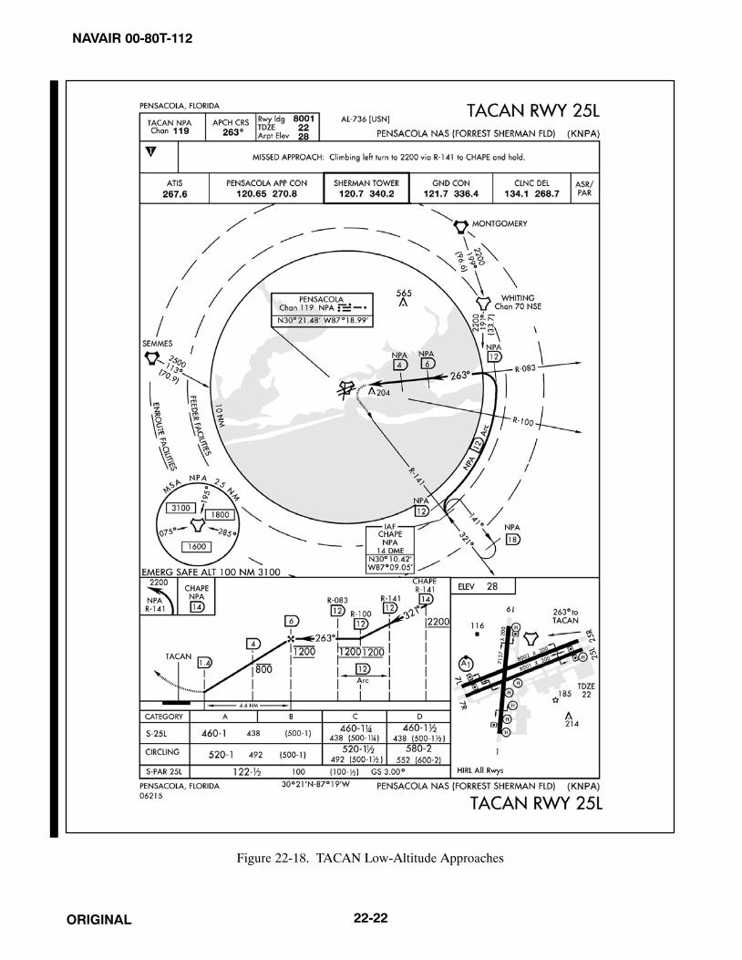
NAVAIR 00-80T-112
ORIGINAL 22-22
Figure 22-18. TACAN Low-Altitude Approaches

NAVAIR 00-80T-112
ORIGINAL23-1
CHAPTER 23
ADF, UHF/ADF, Marker Beacons
23.1 AUTOMATIC DIRECTION FINDING (ADF)
The radio compass low-frequency receiver is capable of Automatic Direction Finding (ADF). Most direction findingequipment will receive any frequency between 100 and 1750 kHz. Most other low-frequency receivers have afrequency range of 190 to 1750 kHz. The en route supplement lists the location and frequency of the Low-Frequency(LF) radio ranges and radio beacons. Those beacons coded SAB provide continuous weather information.
Both high- and low-altitude instrument approaches are found in the applicable terminal approach procedures books.
23.1.1 Automatic Direction Finding (ADF) Procedures
Whenever possible, use a nondirectional radio beacon. Commercial broadcasting stations should be used with cautionbecause some have highly directional radiation patterns. Also, they are not flight-checked for navigational use.Positive identification of the commercial station being used is imperative.
The radio compass automatically determines the bearing to any radio station within its frequency and sensitivityrange. The radio compass also may be used as an auxiliary receiver for the reception of weather broadcasts and otherbroadcast information.
The operation of a radio compass depends chiefly upon the characteristics of a loop antenna. A loop-receiving antennagives maximum reception when the plane of the loop is parallel to, or in line with, the direction of wave travel. Asthe loop is rotated from this position, volume gradually decreases and reaches a minimum when the plane of the loopis perpendicular to the direction of wave travel.
These characteristics of a loop antenna result from the fact that the receiver input from a loop antenna is the resultantof the opposing voltages in the two halves of the loop. When current flows in a looped conductor, it must flow inopposite directions in each half of the loop. This occurs when the plane of the loop is in line with the station. The factthat one side of the loop is closer to the transmitter causes a slight delay between the time the radio wave reaches oneside and the time it reaches the other; therefore, there is a phase difference between the voltages induced in each halfof the loop. This causes a resultant current to flow through the transformer and creates a signal input to the receiver.
When the plane of the loop is parallel to the direction of wave travel, a maximum voltage is induced in the loop, andthe strength of the signals heard in the headset is also at a maximum. Conversely, when the plane of the loop isperpendicular to the direction of wave travel, both sides of the loop are equidistant from the station, and the radio wavereaches both sides of the loop at the same point in its cycle. The induced voltage is theoretically zero, and the strengthof the received signal is at a minimum. This position of the loop is called the null position.
The null position of the loop, rather than the maximum position, is used for direction finding; that is, a bearing isobtained when the plane of the loop is perpendicular to the line on which the radio waves are traveling when they strikethe loop. The null position is preferred because it can be determined more exactly than the maximum. A 25� rotationfrom the maximum position changes total signal strength less than 10 percent, whereas a 25� rotation from theminimum or null position changes the signal strength 50 percent.
With the loop rotated to a null position, the radio station being received is on a line perpendicular to the plane of theloop; however, the direction of the radio station from the aircraft may be either one of two directions 180� apart. Theinability of the loop antenna to determine which of the two possible directions is correct is called the 180� ambiguityof the loop.

NAVAIR 00-80T-112
ORIGINAL 23-2
The 180� ambiguity is eliminated with a nondirectional or sensing antenna.
The loop antenna of the radio compass is automatically rotated to the null position when signals are being receivedover both the sensing and loop antennas. The combination of signals energizes a phasing system that operates a motoron the loop drive. As the motor turns, it rotates the loop. The bearing pointer is electrically synchronized and turnswith the loop, indicating the bearing to the station when the loop has stopped in the null position.
The loop antenna continuously positions itself to remain perpendicular to the station. As the loop antenna can moveabout only one axis (i.e., it can turn but cannot tilt), an error is induced whenever the aircraft is in a banked attitude.This is called dip error. The magnitude of this error depends on the position of the aircraft from the station, its altitudeand range, and the angle of bank used. Dip error is most noticeable when the aircraft is banked and the station is onthe nose or tail of the aircraft. The ADF bearing pointer should be considered as giving accurate bearings only inwings-level flight.
23.1.1.1 Tuning
The radio compass is normally tuned for ADF operation. The ADF feature is used for ease of operation; however,if reception of radio signals is poor due to static, thunderstorms, or distance from the stations, use Manual DirectionFinder (MDF) procedures described later in this section. Since most ADF receivers do not have a “flag” to warn thepilot when erroneous bearing information is being displayed, the pilot should continuously monitor theNon-Directional Beacon (NDB) identification (refer to specific aircraft NATOPS).
NoteSee the appropriate Flight Information Publications (FLIP) en route for theprocedures peculiar to tuning foreign low-frequency stations.
ADF tuning:
1. Interphone control panel and radio compass filter switch as required.
2. Obtain control of the set.
3. Function switch — ANT position.
4. VOICE-CW switch — VOICE.
5. Select the frequency band.
6. Tune to the desired frequency for best audible signal. Under conditions of static and/or interferences, a weakstation can sometimes be tuned by using the LOOP position. When tuning in LOOP, an increase in volume willgenerally be required.
7. Identify the station.
8. Function switch — COMP/ADF position.
9. Retune for maximum needle deflection on the tuning meter.
Tuning with the nonmetered radio control compass panel:
As this control panel does not incorporate a tuning meter, do fine tuning for ADF with the function switch in the ANTposition and the VOICE-CW switch in the CW position. Tune for minimum or zero modulated tone, return theVOICE-CW switch to VOICE and the function switch to ADF, and reidentify the station.

NAVAIR 00-80T-112
ORIGINAL23-3
NoteTuning for zero modulation is an accurate method of obtaining maximumsignal strength and can be used if difficulty is experienced determiningmaximum needle deflection on the tuning meter. See Figure 23-1 forvolume effects on null width.
23.1.1.2 Course Interceptions
Inbound course interceptions may be done identically to those described in paragraph 21.3.3.1. An alternate method:To determine the intercept heading, locate the bearing from the station that you are presently on, the bearing that youwant to intercept, and measure the angular difference. If the angular difference is less than 45�, turn toward the desiredbearing in the shortest direction with an angle of intercept equal to the computed angular difference. The time to thestation will be approximately equal to the time necessary to complete the intercept (Figure 23-2). If the angulardifference is greater than 45�, a series of time-distance check maneuvers (discussed under paragraph 23.1.1.5) maybe performed if distance/time to the station is unknown. The pilot may select any angular interception if timing is notessential, 30� to 45� being generally sufficient (Figure 23-3).
23.1.1.3 Station Passage
23.1.1.3.1 ADF Procedure
When close to the station, the bearing pointer becomes unsteady and erratic due to the area of signal confusion. Thischaracteristic increases with altitude. Also, a small, lateral displacement from the desired course causes a largeoff-course bearing indication. A bearing pointer deflection of 5�, when the aircraft is 10 miles from the station, meansthat the aircraft has departed from the desired course approximately 1 nm, whereas the same 5� displacement at 1mile would represent a distance of approximately 600 feet. Do not chase the bearing pointer when it starts movingrapidly to the side; instead, maintain a constant heading, as the station is very near.
Figure 23-1. Effects of Volume Control on Null Width

NAVAIR 00-80T-112
ORIGINAL 23-4
3
Procedural Steps
1. Tune and identify station.
2. Determine the bearing from the radio beacon you are on (240�) by looking at the tail of the No. 2 needle.
3. Determine the bearing from the radio beacon you desire to intercept (210�).
Visualize this on your heading indicator.
4. Measure the angular difference (30�).
Since it is less than 45�, compute your intercept heading based on the number of degrees in thecomputed angular difference (30�) and your present inbound course to the station (060�). The computedintercept heading would be (090�). Since the bearing visualized on the heading indicator is to the right ofyour present bearing, the 30� is added to your inbound course.
5. Look at your aircraft heading and turn in the shortest direction to the computed intercept heading.
Start the clock.
6. Maintain the intercept heading until a lead point is reached, then complete the intercept.
Lead points depend on the No. 2 needle rate of movement.
Figure 23-2. Inbound Course Interception Less Than 45°

NAVAIR 00-80T-112
ORIGINAL23-5
Figure 23-3. Inbound Course Interception Greater Than 45° (Timed Distance Method) (Sheet 1 of 2)

NAVAIR 00-80T-112
ORIGINAL 23-6
Procedural Steps
1. Tune and identify the station.
2. Determine the bearing from the radio beacon you are on (240�) by looking at the tail of the No. 2 needle.
3. Determine an intercept heading.
a. Determine the bearing from the radio beacon you desire to intercept (330�). Visualize this on theheading indicator.
b. Measure the angular difference (90�).
c. Since it is greater than 45�, compute your initial heading based on the present course to the station(060�) and the figure 70�.
d. Since the shortest direction to the bearing is to the left, subtract 70� from the present course to thestation. The computed initial Magnetic Heading (MH) is 350�.
e. Turn in the shortest direction to the computed initial MH.
4. Intercept sequence.
a. When intercepting the 270� bearing, start the clock and maintain heading.
b. After completing 20� of bearing shift, note the time, start the clock again, and turn the aircraft 20�toward the radio beacon.
c. Continue with the 20� time distance checks until a lead point is reached, then complete the intercept.
d. Lead points depend on the rate of movement of the No. 2 needle.Note
If heading indicators are inoperative, the No. 2 needle will still point to the station. Utilize the magneticcompass to determine bearings and make timed turns.
Figure 23-3. Inbound Course Interception Greater Than 45° (Timed Distance Method) (Sheet 2 of 2)

NAVAIR 00-80T-112
ORIGINAL23-7
Initial station passage is positively determined when the pointer moves through the wingtip position. This usuallyoccurs shortly after the aircraft has actually passed the station. Timing should begin that instant regardless of furtheroscillations.
23.1.1.4 Outbound — Immediately After Station Passage
Turn to parallel the desired outbound course (compensate for wind). Maintain heading and allow the bearing pointerto stabilize. Note the number of degrees between the tail of the bearing pointer and the desired course. To correct backon course, use outbound course interception technique (Figure 23-4).
23.1.1.4.1 Outbound — Away from the Station
First, note the position of the bearing pointer tail. Then, on the compass card, look from the tail in the short directionto the desired course. Any heading beyond the desired course is a no-wind intercept heading. Normally, 45� beyondthe desired course is a good intercept heading as it also forms a 45� or “average” angle of intercept; however, as ininbound intercepts, consider the known factors of groundspeed and distance from the station when selecting anintercept heading. Outbound procedures are essentially identical with those for VHF Omnidirectional Range (VOR)— Radio Magnetic Indicator (RMI) only (Figure 21-9).
23.1.1.4.2 Completing the Intercept
After the intercept heading has been established, adjustments may be required to achieve a more desirable angle orrate of intercept. As the aircraft approaches course, it is necessary to determine a lead point for turning because ofthe radius of turn. The lead point will depend upon the rate of movement of the bearing pointer and the time requiredto complete the turn to course. Factors affecting the lead point are groundspeed, distance from the station, interceptangle, and rate of turn. Complete the turn to course, simultaneously applying a correction for known wind.
23.1.1.5 Time-Distance Check
It is possible to calculate the time and distance from the station using ADF.
23.1.1.5.1 ADF Procedures
After tuning the radio compass for ADF, note the position of the bearing pointer. The number of degrees the bearingpointer is deflected from the wingtip position indicates the magnitude and direction of turn required to place thepointer on the wingtip position. Turn to this predetermined heading. If the bearing pointer is not within 5� of thewingtip position after you have made the turn, make a corrective turn to place it on the wingtip. Note the exact timeat the completion of this turn, and maintain a constant heading until the pointer shows a bearing change of 5� to 20�(Figure 23-5).
23.1.1.6 Tracking
It is possible to maintain a course to or from a station using the radio compass bearing pointer, regardless of whetherthe compass card is working properly or not, because the bearing pointer will point to the station and show the relativebearing of the aircraft to the station.
23.1.1.6.1 Inbound
After completing a turn to course, maintain heading until the bearing pointer shows a deflection from the desiredcourse. Turn toward the pointer and beyond a sufficient number of degrees to return to course.
After reintercepting course with the correct wind drift correction applied, the pointer will continue to point to thedesired course and be displaced from the top index the number of degrees equal to the applied drift correction. If thepointer moves toward the top index, the correction is too small; if it moves away from the top index, the correctionis too large (Figure 23-6).

NAVAIR 00-80T-112
ORIGINAL 23-8
Figure 23-4. Course Interception Immediately After Station Passage (Sheet 1 of 2)

NAVAIR 00-80T-112
ORIGINAL23-9
Outbound Procedural Steps — ONLY
1. Tune and identify the station.
This should already be accomplished.
2. Turn in the shortest direction to a heading that will parallel or intercept the outbound course.
Turning to parallel the desired outbound course is always acceptable. Continuing the turn to an interceptheading may be preferable when the bearing pointer is stabilized or when the pilot knows the aircraftposition in relation to the desired course. The effect that airspeed, wind, and magnitude of turn will haveon aircraft position during the turn to an intercept heading should be carefully considered.
3. Determine number of degrees off course.
Note the angular difference between the tail of the bearing pointer and the desired course.
4. Determine an intercept heading.
If a suitable intercept angle was not established during the initial turn, look from the tail of the bearingpointer to the desired course. Any heading beyond the desired course is a no-wind intercept heading.Turn in this direction an amount approximately equal to the number of degrees off course. Normally, toavoid overshooting the course, do not use an intercept angle greater than 45�.
NoteOn some aircraft, the RMI/Bearing-Distance-Heading Indicator (BDHI) bearing pointer does not have a tail.In this case, turn to the magnetic heading of the desired course. Continue on the outbound magnetic headingof the desired course until the bearing pointer stabilizes. Note the number of degrees the bearing pointer isoff the tail of the aircraft. This is the number of degrees off course. Any heading change in the direction towardthe head of the bearing pointer is a no-wind intercept heading. Turn in the direction of the head of the bearingpointer an amount approximately equal to the number of degrees off course. Normally, to avoid overshootingthe course, do not use an intercept angle greater than 45�.
5. Turn to an intercept heading, if not previously accomplished.
6. Maintain the intercept heading until a lead point is reached, then complete the intercept.
Lead point depends on bearing pointer rate of movement and the time required to turn on course.
Figure 23-4. Course Interception Immediately After Station Passage (Sheet 2 of 2)

NAVAIR 00-80T-112
ORIGINAL 23-10
23.1.1.6.2 Outbound
To maintain an outbound course, use outbound course interception procedures. Apply corrections to keep the desiredcourse under the tail of the bearing pointer. After applying a wind drift correction outbound, and the tail of the pointermoves toward the top index, the drift correction is too large; if it moves away from the top index, the drift correctionis too small (Figure 23-7).
For ease of computation, it is desirable to use 10� of bearing change. When the bearing pointer shows the desiredbearing change, again note the exact time. Turn immediately to place the bearing pointer under the top index andmaintain that course to the station. Determine the time to the station by applying the following formula:
Time in seconds between bearingsDegrees of bearing change
� Minutes to station.
For example, if it requires 2 minutes (120 seconds) to fly a bearing change of 10�, the aircraft is:
120
10 = 12 minutes to the station.
The time from the station may also be calculated by using a short method based on the above formula, provided a10� bearing change is flown. If the elapsed time for the bearing change is noted in seconds and a 10� bearing changeis made, the time from the station in minutes is determined by counting off 1 decimal point; thus, if it requires 75seconds to fly a 10� bearing change, the aircraft is 7.5 minutes from the station.
When the bearing pointer is moving rapidly or when several corrections are required to place the pointer on thewingtip position, the aircraft is very close to the station. For all practical purposes, this can be considered stationpassage.
The distance from the station may be computed by multiplying True Airspeed (TAS) or groundspeed (in miles perminute) by the previously determined time in minutes. For example, if the aircraft is 4 minutes from the station, flyingat a TAS of 300 knots (or 5 nm per minute), the distance from the station is:
5 � 4 = 20 nm.
The preceding are methods of computing approximate time and distance. For increased accuracy, use only a smallamount of bearing change (about 10�) and correct for existing winds.
By flying a constant heading and checking the time and bearing progression closely, you can determine the estimatedtime of arrival over the station, or the position and distance from a station not directly on the flightpath.
23.1.1.7 Homing
Homing is essentially keeping the nose of the aircraft pointed at the station while proceeding inbound. As homingin a crosswind will result in a curved flightpath to the station, use it only for short distances (i.e., transition from oneradio facility to another in the immediate area) (Figure 23-8).
NoteHoming is not an accepted instrument procedure.
23.1.1.7.1 ADF Homing Procedures
Observe the position of the radio compass bearing pointer and turn in the shorter direction to place the head of thebearing pointer under the top index of the compass card. Maintain this indication while proceeding to the station.
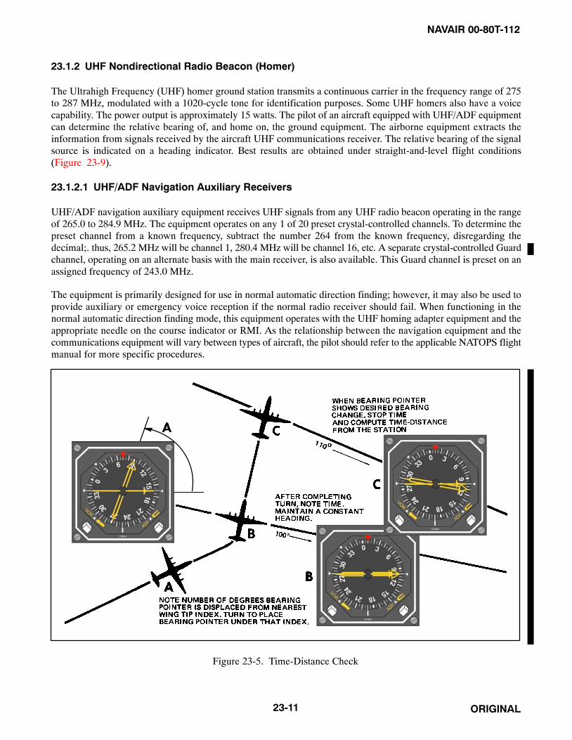
NAVAIR 00-80T-112
ORIGINAL23-11
23.1.2 UHF Nondirectional Radio Beacon (Homer)
The Ultrahigh Frequency (UHF) homer ground station transmits a continuous carrier in the frequency range of 275to 287 MHz, modulated with a 1020-cycle tone for identification purposes. Some UHF homers also have a voicecapability. The power output is approximately 15 watts. The pilot of an aircraft equipped with UHF/ADF equipmentcan determine the relative bearing of, and home on, the ground equipment. The airborne equipment extracts theinformation from signals received by the aircraft UHF communications receiver. The relative bearing of the signalsource is indicated on a heading indicator. Best results are obtained under straight-and-level flight conditions(Figure 23-9).
23.1.2.1 UHF/ADF Navigation Auxiliary Receivers
UHF/ADF navigation auxiliary equipment receives UHF signals from any UHF radio beacon operating in the rangeof 265.0 to 284.9 MHz. The equipment operates on any 1 of 20 preset crystal-controlled channels. To determine thepreset channel from a known frequency, subtract the number 264 from the known frequency, disregarding thedecimal;. thus, 265.2 MHz will be channel 1, 280.4 MHz will be channel 16, etc. A separate crystal-controlled Guardchannel, operating on an alternate basis with the main receiver, is also available. This Guard channel is preset on anassigned frequency of 243.0 MHz.
The equipment is primarily designed for use in normal automatic direction finding; however, it may also be used toprovide auxiliary or emergency voice reception if the normal radio receiver should fail. When functioning in thenormal automatic direction finding mode, this equipment operates with the UHF homing adapter equipment and theappropriate needle on the course indicator or RMI. As the relationship between the navigation equipment and thecommunications equipment will vary between types of aircraft, the pilot should refer to the applicable NATOPS flightmanual for more specific procedures.
Figure 23-5. Time-Distance Check

NAVAIR 00-80T-112
ORIGINAL 23-12
Figure 23-6. Maintaining Course Inbound
Figure 23-7. Maintaining Course Outbound

NAVAIR 00-80T-112
ORIGINAL23-13
Figure 23-8. Curved Flightpath as a Result of Homing with a Crosswind Condition

NAVAIR 00-80T-112
ORIGINAL 23-14
Figure 23-9. Automatic Direction Finding Signal Pattern
23.1.2.2 UHF Homing Adapters
These systems are used with UHF transceivers as a navigational aid. They provide a continuous indication of theapproximate relative bearing of an RF signal source transmitted by another aircraft, surface craft, or ground stationon a frequency range of 225.0 to 399.9 MHz. The approximate relative bearing will be indicated by the appropriateneedle on the course indicator or RMI.
Whenever the function selector switch on the UHF control panel is set to the T/R or T/R+G position, the homingequipment will automatically be placed in the standby condition. When this selector is set to ADF, the commandequipment is placed in circuit with the homing equipment, enabling the latter to receive the frequency selected bythe channel selector switch on the command set control panel. In the ADF position, the auxiliary guard receivingcapability will be lost.
23.1.2.3 Approach Procedures
ADF procedures for holding, high-altitude penetration and approach, procedure turn and approach, and missedapproach are the same as those for VOR (refer to Chapter 21) except that normal ADF interception procedures areused. Remember, dip error in turns causes erroneous bearing indications; therefore, make all turns to predeterminedheadings (Figures 23-10 and 23-11).
23.2 MARKER BEACONS
Marker beacons serve to identify a particular location in space along an airway or on the approach to an instrumentrunway. This is done by means of a 75-MHz transmitter that transmits a directional signal to be received by aircraftflying overhead. These markers are generally used in conjunction with low-frequency radio ranges and the InstrumentLanding System (ILS) as point designators. Four classes of markers are now in general use: Frequency Modulation(FM), Low-Power Fan Marker (LFM), station location or Z-markers, and the ILS marker beacons.

NAVAIR 00-80T-112
ORIGINAL23-15
FM and LFM fan markers are keyed to indicate on which radio range course they are located. The radio range coursesare numbered clockwise beginning at true north with the north (or near north) course being designated No. 1. Fanmarkers located on course number one are keyed to emit single dashes, those on course two, two dashes, etc. Whentwo fan markers are located on the same radio range course, the identification of the outermost marker is precededby two dots; thus, the identification of the outermost marker on a number one course is two dots and one dash.
The class FM fan markers are used to provide a positive identification of positions at definite points along the airways.The transmitters have a power output of approximately 100 watts. Two types of antenna array are used with class FMfan markers. The first type, generally referred to as the standard type, produces an elliptical-shaped pattern, whichat an elevation of 1,000 feet above the station is approximately 4 miles wide and 12 miles long. At 10,000 feet, thepattern widens to approximately 12 miles wide and 35 miles long. (The long axis lies across the airway or radio range.)
The second array produces a dumbbell or boneshaped pattern, which at the “handle” is approximately 3 miles wideat 1,000 feet. The boneshaped marker is preferred at approach control locations where timed approaches are used.
The class LFM or low-power fan markers have a rated power output of 5 watts and are usually located within 5 milesof the radio range stations with which they are associated. The antenna array produces a circular pattern, whichappears elongated at right angles to the airway due to the directional characteristics of the aircraft receiving antenna.
The station location, or Z-marker, was developed to meet the need for a positive position indicator for aircraftoperating under instrument flying conditions to show the pilot when the aircraft was passing directly over alow-frequency radio range station. The marker consists of a 5-watt transmitter and a directional antenna array thatis located on the range plot between the towers or the loop antennas.
ILS marker beacon information is included in paragraph 24.2.1.3.

NAVAIR 00-80T-112
ORIGINAL 23-16
Figure 23-10. Typical ADF High-Altitude Penetration and Approach

NAVAIR 00-80T-112
ORIGINAL23-17/(23-18 blank)
Figure 23-11. Typical ADF Low-Altitude Approach

NAVAIR 00-80T-112
ORIGINAL23-1/(23-2 blank)

NAVAIR 00-80T-112
ORIGINAL24-1
CHAPTER 24
Instrument Landing System (ILS)
24.1 INTRODUCTION
The Instrument Landing System (ILS) (Figure 24-1) is a precision approach system that provides azimuth andglideslope information to the pilot. It consists of a highly directional localizer (course) and glideslope transmitter withassociated marker beacons, compass locators, and, at some sites, Distance Measuring Equipment (DME). The systemis automatically monitored and provides changeover to a standby localizer or glideslope transmitter when the mainsystem malfunctions.
The system may be divided functionally into three parts:
1. Guidance information: localizer, glideslope.
2. Range information: marker beacon, DME.
3. Visual information: approach lights, touchdown and centerline lights, runway lights.
24.2 EQUIPMENT AND OPERATION
24.2.1 Ground Equipment
24.2.1.1 Localizer Transmitter
Localizer transmitters are located approximately 1,000 feet beyond and to the side of the nonapproach end of the ILSrunway. The antenna is in line with the runway centerline. The 90- and 150-cycle signal patterns are radiated onopposite sides of the extended runway centerline. The 150-cycle signal is on the right when looking at the runwayfrom the outer marker; the 90-cycle signal is on the left. The course is formed along the runway centerline extended(toward outer marker) where the signals overlap and are of equal strength. This course is referred to as the front course.The front course envelope is approximately 5� wide, extending 2-1/2� either side of the course centerline. Mostlocalizer transmitters also provide a signal pattern around the runway so that course signals also overlap in theopposite direction, forming a back course. There are few published ILS back course approaches and a glideslope isnot provided for them.
CAUTION
Unless the aircraft ILS equipment includes reverse sensing capability,when flying inbound on the back course it is necessary to steer the aircraftin the direction opposite the needle deflection when making correctionsfrom off-course to on-course. This “flying away from the needle” is alsorequired when flying outbound on the front course of the localizer. Do notuse back course signals for approach unless a back course approachprocedure is published for that particular runway and the approach isauthorized by Air Traffic Control (ATC).
On aircraft without reverse sensing capability, selecting the front course on your Course Deviation Indicator (CDI)will prevent the need to fly away from needle deflection. The CDI will deflect in the proper direction, whether youare on a back course or outbound on a front course.

NAVAIR 00-80T-112
ORIGINAL 24-2
Figure 24-1. Instrument Landing System

NAVAIR 00-80T-112
ORIGINAL24-3
ILS localizer transmitters use the odd decimal VHF frequencies from 108.1 to 111.9 MHz (e.g., 110.3 MHz). Thelocalizer transmitter emits continuous identification in the form of a coded three-letter station identifier preceded bythe letter I (e.g., I-EMH). Some have voice transmission capabilities.
NoteMomentary localizer flag activity and course aberrations may be observedwhen other aircraft cross over the localizer antenna or are in a position toaffect the radiated signal.
24.2.1.2 Glideslope
1. The Ultrahigh Frequency (UHF) glideslope transmitter, operating on 1 of the 20 ILS channels within thefrequency range 329.3 to 335.0 MHz, radiates its signals principally in the direction of final approach. Anyinstrument indications of a glideslope at azimuths other than those within the angular width of the localizerfront course should be disregarded.
2. The glideslope transmitter is located between 750 and 1,250 feet from the approach end of the runway (downthe runway) and offset 400 to 600 feet from the runway centerline. It transmits a glideslope beam 1.4� wide.
3. The glideslope projection angle is normally adjusted to 2.5� to 3� above horizontal so that it intersects themiddle marker at approximately 200 feet and the outer marker at approximately 1,400 feet above the runwayelevation.
4. In addition to the desired glideslope, false course and reversal in sensing will occur at vertical anglesconsiderably greater than the usable slope. The proper use of the glideslope requires that the pilot maintainalertness as the glideslope interception is approached and interpret correctly the “fly-up” and “fly-down”instrument indications to avoid the possibility of attempting to follow one of the higher angle courses.
5. Extreme caution should be used to avoid exceeding a deviation of one dot (or approximately one-half scale)below the glideslope up to the middle marker and to avoid any deviation below the glideslope from the middlemarker to completion of landing.
6. The glideslope facilities provide a signal that flares from 18 to 27 feet above the runway; therefore, theglideslope should not be expected to provide guidance completely to a touchdown point on the runway.
7. DME may be installed at the glideslope transmitter site. Range and the three-letter station identifier areavailable through the Tactical Air Navigation (TACAN) receiver. Bearing information is not provided.
24.2.1.3 Marker Beacons
Marker beacons are very low-powered, 75-MHz transmitters located along the ILS final approach course to mark aspecific position. Normally, two marker beacons are used for this purpose, and they are depicted on the terminal chartby the letters OM and MM (Outer Marker and Middle Marker).
An additional beacon called an Inner Marker (IM) may also be installed. The beacons are identified in the aircraftvisually (marker beacon light) and/or aurally depending on aircraft equipment. The reception area of the aural signalis larger than that of the visual signal. Marker beacons are not installed for navigation purposes but merely to indicatea fix on the localizer course.
The Outer Marker (OM) is normally located 4 to 7 miles from the end of the runway. Outer marker identificationconsists of continuous dashes. Aurally, the dashes are comparatively low pitched (400 Hz). The published altitudeat the outer marker is what the altimeter should indicate when the aircraft is over the marker and on the glideslope;however, there are no specific limits. The outer marker altitude may also be the procedure turn or glideslopeinterception altitude.
NAVAIR 00-80T-112
ORIGINAL 24-4
The Middle Marker (MM) is located approximately 3,500 feet from the runway and is identified by alternating dotsand dashes. The aural signal is comparatively high pitched (1,300 Hertz) and easily distinguished from the outermarker signal. This is also the position where an aircraft on glidepath will be at an altitude of approximately 200 feetabove the elevation of the touchdown zone.
The IM, where installed, will indicate a point at which an aircraft is at a designated Decision Height (DH) for CategoryII equipped aircraft on the glideslope between the middle marker and landing threshold. The IM is modulated at 3000Hz and identified with continuous dots keyed at the rate of six dots per second.
24.2.1.4 Compass Locators
If installed, compass locators are placed at the marker beacon sites (usually only at the OM) as aids to navigationaround the ILS. They are low-powered nondirectional radio beacons operating between 200 and 415 kHz with areliable reception range of at least 15 nm; however, higher-powered, low-frequency nondirectional radio beaconsmay be collocated with the marker beacons and used as compass locators. These generally carry transcribed weatherbroadcast information.
On the approach chart, the radio data information box for the locator is broken at the top by the letter L. Within thebox are the frequency and the identification of the facility.
The locator identification consists of two letters. When installed at an outer marker, it will normally transmit the firsttwo letters of the three-letter ILS localizer identification. If installed at a middle marker, it will transmit the last twoletters. For example, with an ILS localizer identified by the letters I-FAT, the compass locator identification at theouter marker is FA, and at the middle marker is AT. On the profile view of the approach chart, the locators are depictedby the letters LOM or LMM (Locator Outer Marker or Locator Middle Marker).
During periods of routine or emergency maintenance, the coded identification (or code and voice, where applicable)will be removed from ILS localizers but not from Non-Directional Beacon (NDB) compass locators or 75-MHzmarker beacons (Figure 24-1).
NoteILS minimums, with all components operative, normally establish a DH(decision height MSL) with a Height Above Touchdown (HAT) of 200 feetand a visibility of one-half statute mile.
24.2.2 Airborne Equipment
The control panel for tuning the ILS localizer is the same as that used for VHF Omnidirectional Range (VOR) in mostaircraft. The glideslope receiver is automatically tuned when the localizer frequency is selected.
A course indicator is used in this chapter to illustrate procedures for flying ILS. The flight director display is illustratedin Figure 24-3.
The radio magnetic indicator has no function with ILS frequencies; however, bearing information to other radiofacilities (compass locators, TACAN, etc.) can be of considerable value. All available navigation equipment shouldbe used when appropriate during any approach.
24.2.2.1 ILS Channel/Frequency
ILS are being commissioned utilizing all 20 channels allotted to ILS by International Civil Aviation Organization(ICAO) in Aeronautical Telecommunications Annex 10. Aircraft equipment should be checked to ensure thereceiving capability of all channels.

NAVAIR 00-80T-112
ORIGINAL24-5
24.3 ILS PROCEDURES
24.3.1 Performing the ILS Approach
Information for planning an ILS and transitioning to it from other Navigation Aids (NAVAIDs) is found in theterminal flight information publications (Figure 24-2). The approach should be considered in its entirety from en routetransition through landing or missed approach. Refer to other Flight Information Publications (FLIP) documents suchas Planning and the En Route IFR Supplement.
Pilots should tune the ILS receiver and identify and monitor the localizer identification signal as soon as practicalduring the transition procedure. The course and glideslope indicators are reliable only when (1) their warning flagsare not displayed, (2) the localizer identifier is received, and (3) the aircraft is within the usable range of theequipment. The localizer is considered reliable within 18 miles of the transmitter within 10� or 10 miles within 35�of the course centerline unless the published approach depicts a transition point at a farther distance. The glideslopeinterception point and altitude are designated on the terminal chart; the glideslope is considered reliable within 10miles of the transmitter, provided the aircraft is on the localizer course.
Before localizer interception, set the published front course in the course selector window so that the aircraftheading/localizer relationship is displayed on the course indicator. The transition may require a large turn onto thelocalizer course (e.g., a teardrop penetration or procedure turn). If the CDI indicates full-scale deflection (coursedeviation 2-1/2� or greater) during the latter portion of the turn, roll out with an intercept angle that will ensurelocalizer interception prior to the glideslope intercept point. Normally a 30� to 45� intercept is sufficient; however,groundspeed, distance from the localizer course, and final approach fix may require another intercept angle.
When the localizer is intercepted, maintain the published heading until the first movement of the CDI. The rate ofCDI movement will aid in estimating the force and direction of the wind. Heading corrections should be sufficientto stop the CDI movement and return the aircraft to course. After returning to course, apply the drift correctionnecessary to keep the CDI centered. Heading corrections should be reduced as the aircraft continues inbound(increments of 5� or less are usually sufficient).
The pilot should maintain the glideslope interception altitude, configure the aircraft for landing, and establish the finalapproach airspeed before reaching the glideslope intercept point. Do not descend below glideslope interceptionaltitude if the CDI indicates full-scale deflection. Call the controlling agency at the final approach fix or as directed.
As the Glideslope Indicator (GSI) moves downward from its upper limits, prepare to intercept the glideslope. Slightlybefore the GSI reaches the center position, establish a pitch attitude on the attitude indicator and a power setting thatwill result in the vertical velocity and airspeed required to maintain the glidepath. The amount of pitch changerequired will depend on the glideslope angle. One technique that may be used when intercepting the glideslope(provided the final approach airspeed and configuration have been established) is to change the pitch attitude on theattitude indicator the same number of degrees as the glideslope angle (i.e., normally 2-1/2� to 3�).
The glideslope facility provides a path that flares from 18 to 27 feet abovethe runway; therefore, the glidepath should not be expected to provideguidance completely to a touchdown point on the runway.
Corrections are made using coordinated pitch and power changes. Normally pitch changes should result in verticalvelocity changes of less than 300 fpm. A 1� pitch change on the attitude indicator is usually a sufficient amount ofcorrection to achieve a vertical velocity change of 200 to 300 fpm for groundspeeds between 120 and 180 knots.
As indicated in Figure 24-3, the size of the course and glideslope envelope reduces progressively throughout theapproach; therefore, the size of the pitch and bank corrections should be gradually reduced as the distance totouchdown decreases.

NAVAIR 00-80T-112
ORIGINAL 24-6
Figure 24-2. Typical ILS Approach

NAVAIR 00-80T-112
ORIGINAL24-7
A Front Course Approach − Turningto intercept the ILS Localizer B Rolling out — on course,
glideslope above aircraft.
A
A B
B C
C
D
D
E
E
F
F
LOCALIZER
GLIDESLOPE
NOTE: NOT TO SCALE
Figure 24-3. Course Indicator Presentation (Front Course) (Sheet 1 of 2)

NAVAIR 00-80T-112
ORIGINAL 24-8
C Left of course,on glideslope. D Left of course, correct right,
glideslope below aircraft.
E Right of course, correct left,glideslope above aircraft. F On course.
On glideslope.
Figure 24-3. Course Indicator Presentation (Front Course) (Sheet 2 of 2)

NAVAIR 00-80T-112
ORIGINAL24-9
The most common tendency when flying an ILS approach is to “fly” the CDI and GSI. An ILS approach is a basicinstrument maneuver similar to a radar approach. Immediate and smooth corrections should be made on the controlinstruments based on aircraft and flightpath performance indications. The importance of precise aircraft controlcannot be overemphasized. Lateral distances in relation to CDI displacement can be considerable, especially atinstallations where the distance from the localizer transmitter at minimum altitude may be more than 2 miles. Forexample, in the lateral deviation chart of Figure 24-4, a full-scale deviation at 1 mile from touchdown places theaircraft 617 feet from the centerline. If the CDI was deflected 2� at a missed approach point 1/2 nm from the end ofthis runway, the aircraft would be approximately 400 feet from the centerline. Do not attempt to fly the final approachwith full-scale deflection on the CDI or GSI, as obstruction clearance will not be assured; consideration should begiven to executing a missed approach.
The most critical period of the approach occurs while the pilot is busy maintaining course, glidepath, and airspeed,and is approaching the published DH. Ensure the altimeter is being included in the cross-check. The DH is the lowestaltitude at which a missed approach will be initiated if sufficient visual reference with the runway environment hasnot been established. Perform the missed approach when:
1. At the DH and visual reference with the runway environment is insufficient to complete the landing (runwayor runway/approach lights).
2. Instructed by the controlling agency.
3. A safe landing is not possible.
Figure 24-4. Course and Glideslope Deviation vs. Actual Displacement from Touchdown

NAVAIR 00-80T-112
ORIGINAL 24-10
If the course warning flag is displayed during the final approach, initiate themissed approach procedure. If the glideslope warning flag is displayed, theapproach should be flown no lower than the published localizer-onlyaltitude or, if not published, no lower than circling-minimum altitude for theaircraft category. Localizer-only approaches are planned for and flown asa nonprecision approach.
24.3.2 Localizer Approaches
Most Navy aircraft do not have glideslope capability, but may execute an ILS approach as a localizer approach. Inthis case, proceed as outlined for a full ILS approach. A localizer approach is a nonprecision approach and the pilotshould execute a missed approach when he has reached the missed approach point and the runway environment isnot in sight.
Note
Many ILS missed approach procedures require the use of VOR; hence,pilots may have to retune their VOR receiver.
The Localizer-type Directional Aid (LDA) is of comparable utility and accuracy to a localizer, but is not part of acomplete ILS. The LDA will not be aligned with the runway, but the angle of divergence will not exceed 30�.
24.3.3 Simplified Directional Facility (SDF)
The Simplified Directional Facility (SDF) provides a final approach that is similar to that of the ILS localizer andLDA; however, the SDF may have a wider course width of 6� or 12�. It does not provide glideslope information. TheSDF transmits on frequencies 108.10 to 111.95 MHz. For the pilot, the approach techniques and procedures used inthe performance of an SDF instrument approach are essentially identical to those employed in executing a standardno-glideslope localizer approach, except that the SDF course is seldom aligned with the runway and the course maybe wider, resulting in less precision.
24.3.4 Radar Vectors
When being radar vectored to an ILS final, the pilot should retain the radar service until established at a point wherea transition to the published procedure can be made. The controller should establish the aircraft with a 30� or lessintercept angle to the localizer course at an altitude that will intercept the glideslope before the final approach fix.When the controller issues the final vector, altitude, and clearance for the approach, the pilot must know his positionin relation to the airfield. If the aircraft is at a range beyond the coverage of the approach chart, maintain the lastassigned ATC altitude until within the area depicted on the approach chart. When within the area depicted on theapproach chart and after intercepting the localizer, the pilot may follow those altitudes depicted on the approach chartat the specified fixes. Query the controller if there is any doubt concerning position or altitude clearance.
Note
Use radar monitoring service, when available, as an additional source ofinformation.

NAVAIR 00-80T-112
ORIGINAL24-11
24.3.5 Localizer (LOC) Back Course Approach
Localizer (LOC) back course (Figures 24-5 and 24-6) approaches are nonprecision approaches and glideslopeinformation is not provided. To maintain the proper aircraft heading/localizer course relationship, set the publishedfront course in the course selector window. When inbound on the back course or outbound on the inbound course,the heading pointer will be in the bottom half of the course indicator. Turning to place it toward the CDI in the lowerhalf of the instrument case will correct the aircraft toward course. Back course approaches are flown using techniquessimilar to those for localizer approaches.

NAVAIR 00-80T-112
ORIGINAL 24-12
PUBLISHED FRONT COURSESET IN COURSE SELECTORWINDOW.
A
B C
Figure 24-5. Course Indicator Presentations

NAVAIR 00-80T-112
ORIGINAL24-13/(24-14 blank)
Figure 24-6. LOC Back Course Approach

NAVAIR 00-80T-112
ORIGINAL24-1/(24-2 blank)

NAVAIR 00-80T-112
ORIGINAL25-1
CHAPTER 25
Radar Approaches
25.1 INTRODUCTION
The word radar is derived from the words radio detection and ranging. Radar equipment determines the distance anddirection of objects by transmission and return of radio waves.
Radar is used in many ways to increase operational effectiveness. One of its principal uses is to provide a precisionapproach system for aircraft landing during conditions of restricted visibility and/or low ceilings.
25.1.1 Principles of Radar
The basic principle of radar may be stated in a a single word — reflection. An echo is a simple demonstration of thereflection of sound waves. A radiated noise strikes a reflecting surface and is returned to its source. The time lagbetween the original sound and its echo is directly proportional to the distance the sound must travel. This sameprinciple applies in the use of radio waves.
The frequency band used contains very short radio waves of ultrahigh or super-high frequency that travel, essentially,in a straight line and are easily reflected from objects in their path.
Longer radio waves are not as easily reflected; they continue around obstacles and tend to follow the curvature of theEarth.
A very short radio wave is produced and transmitted in a certain direction in the form of a short pulse lasting fromone-half to several microseconds (millionths of a second). When this pulse strikes a reflecting surface, some of thereflected waves return to the point of origin, where the energy is picked up by a receiver. Multiplying the time intervalby the velocity of the radio waves and dividing the product by two gives the distance to the reflecting object(Figure 25-1).
The best means of presenting the return of the echo is by use of cathode-ray tubes, commonly called scopes. Withthis type presentation, the object (aircraft) reflecting the radio wave appears as a pip on a scope. Through scopeinterpretation, the radar controller determines position, range, and also elevation of the aircraft during a precisionapproach.
25.1.2 Radar Traffic Information Service
Radar Traffic Information Service advises pilots of any radar target observed in the proximity that warrants attention.This service does not relieve pilots of their responsibility to see and avoid. The surveillance radar used by Air TrafficControl (ATC) does not provide altitude information on aircraft that are not equipped with Mode C. Several factorsinfluence the availability of radar traffic information services (e.g., weather, controller workload, and traffic volume).Traffic information is provided to all aircraft operating on an IFR Flight Plan, unless operation in Class A airspaceor the pilot declines service. When receiving Visual Flight Rules (VFR) advisory service, pilots should monitor theassigned frequency at all times and advise the controller when changing VFR cruising altitude. When the service isno longer required, advise ATC and change transponder code to 1200.
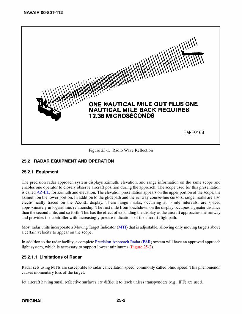
NAVAIR 00-80T-112
ORIGINAL 25-2
Figure 25-1. Radio Wave Reflection
25.2 RADAR EQUIPMENT AND OPERATION
25.2.1 Equipment
The precision radar approach system displays azimuth, elevation, and range information on the same scope andenables one operator to closely observe aircraft position during the approach. The scope used for this presentationis called AZ-EL, for azimuth and elevation. The elevation presentation appears on the upper portion of the scope, theazimuth on the lower portion. In addition to the glidepath and the runway course-line cursors, range marks are alsoelectronically traced on the AZ-EL display. These range marks, occurring at 1-mile intervals, are spacedapproximately in logarithmic relationship. The first mile from touchdown on the display occupies a greater distancethan the second mile, and so forth. This has the effect of expanding the display as the aircraft approaches the runwayand provides the controller with increasingly precise indications of the aircraft flightpath.
Most radar units incorporate a Moving Target Indicator (MTI) that is adjustable, allowing only moving targets abovea certain velocity to appear on the scope.
In addition to the radar facility, a complete Precision Approach Radar (PAR) system will have an approved approachlight system, which is necessary to support lowest minimums (Figure 25-2).
25.2.1.1 Limitations of Radar
Radar sets using MTIs are susceptible to radar cancellation speed, commonly called blind speed. This phenomenoncauses momentary loss of the target.
Jet aircraft having small reflective surfaces are difficult to track unless transponders (e.g., IFF) are used.

NAVAIR 00-80T-112
ORIGINAL25-3
Figure 25-2. Typical Radarscopes
Because of the short wavelength used by radar, rain droplets, snow, and the like cause scope clutter. This makes scopeinterpretation difficult during heavy rain or other heavy precipitation. Later model radar sets use circular polarization(a grid placed over the antenna) to help eliminate clutter caused by precipitation. The radar controller uses circularpolarization only if there is a possibility of losing the target in precipitation clutter. With circular polarization, thecontroller might unknowingly vector an aircraft through areas of intense precipitation, so the pilot will be advisedof possible flight through precipitation not visible on the radarscope.
25.3 RADAR APPROACH PROCEDURES
25.3.1 Radar Approaches
Radar control is one of the most precise methods used for accomplishing an instrument approach. A radar approachsystem consists of Airport Surveillance Radar (ASR) and/or Precision Approach Radar (PAR), controllers, andassociated communication equipment. Controllers interpret radar displays and transmit course and glideslopeinformation to the pilot. As directed, the pilot maneuvers the aircraft to a position from which it can safely land.
Information as to radar availability, frequencies, minimums, glideslope angle, and type of approach can be found inFlight Information Publications (FLIP). The FLIP terminal approach charts provide runway and airfield pictorialpresentations (i.e., obstructions, approach lighting, length and width of runways, and the relative positions ofnavigational aids). When planning for a radar approach, check the en route supplement, terminal charts, and Noticesto Airmen (NOTAMs).
There are three basic types of approaches: the precision approach, the nonprecision (surveillance) approach, and theAutomated Carrier Landing System (ACLS) automatic approach. The precision approach provides the pilot withprecise course, glideslope, and range information. The surveillance approach provides only course and rangeinformation and is classified as a nonprecision approach. Both the precision and nonprecision approaches are divided

NAVAIR 00-80T-112
ORIGINAL 25-4
into two segments: transition to final, and the final approach segment. The ACLS approach is discussed in theappropriate NATOPS manual.
25.3.1.1 Transition to Final
The transition to final segment of the approach is controlled by surveillance radar equipment. This segment includesall maneuvering up to a point where the aircraft is inbound on the final approach course and approximately 8 nm fromtouchdown. During the transition to final, the radar controller directs heading and altitude changes as required toposition the aircraft on final approach. Turns and descents should be initiated immediately after instructions arereceived. Perform turns by establishing an angle of bank on the attitude indicator, which will approximate a standardrate turn for the True Airspeed (TAS) flown (not to exceed 30� of bank). When the aircraft or mission characteristicsdictate very low turn rates, it is advisable to inform the controller. The controller uses this information to assist indetermining lead points for turns and/or corrections.
As lost communication instructions must be noted and understood, and they are not generally available to the pilotin published form, the controller transmits them. In addition, the controller gives changes in current weather, directionof landing, runway information, and the latest altimeter setting.
While transitioning to final, at NAS, the pilot is advised to perform a prelanding cockpit check. Perform the checkand review approach minimums, lost communications procedures, final approach airspeed, and approximate initialrate of descent desired (consider glideslope angle and groundspeed of the aircraft). In addition, use all navigationalreceivers to remain position oriented and/or ready to comply with lost communications procedures. Throughout thissegment, the controller will periodically advise you of the aircraft position relative to the airfield. Do not hesitate torequest additional information.
25.3.1.2 Precision Final Approach
The precision final approach starts when the aircraft is within range of the precision radar and contact is establishedwith the final controller. A precision approach radar system includes two antennas, one scanning vertically and theother scanning horizontally. The range is limited to 10 miles, azimuth to 20 degrees, and elevation to 7 degrees. Theinitial call to the final controller should include the last assigned heading, altitude, and the current status of the gear,if applicable. The required final approach airspeed and configuration should be set prior to glideslope interception,and the landing checklist completed in accordance with the appropriate NATOPS flight manual. The controller willadvise the pilot of any change in lost communications procedures. These procedures must be noted and understood.Upon request, the controller will furnish the pilot with the published decision height.
When the controller advises that the aircraft is intercepting glideslope, adjustment of the power and/or drag devicesis required to establish the predetermined rate of descent. Adjust the pitch attitude on the attitude indicator to maintainthe final approach speed. When the airspeed and glidepath are being maintained, note the power, attitude, and verticalvelocity. Use the values as guides during the remainder of the approach.
If the aircraft is observed to deviate above or below the glidepath, the pilot is given the relative amount of deviationby use of terms “slightly” or “well” and asked to adjust the rate of descent to return to the glidepath. Correct thesedeviations with coordinated pitch and power changes. Maintain a constant airspeed during the approach. When powerchanges are required, avoid excessive throttle movements. Corrections should be made immediately after instructionsare given or when deviations from established attitude or performance indications are desired to return the aircraftto the glidepath.
Accuracy of heading is important for runway alignment during the final approach phase. When instructed to makeheading changes, make them immediately. Instructions to turn are preceded by the phrase “turn right” or “turn left.”To prevent overshooting, the angle of bank should approximate the number of degrees to be turned, not to exceed a1/2 standard rate turn. At high final approach speeds, a larger angle of bank may be required to prevent a prolongedcorrection, but do not exceed the 1/2 standard rate turn. After a new heading is directed, the controller assumes it isbeing maintained. Additional heading corrections will be based on the last assigned heading.

NAVAIR 00-80T-112
ORIGINAL25-5
If an aircraft is observed by the controller to proceed outside of specified safety zone limits in azimuth and/or elevationand continue to operate outside these prescribed limits, the pilot will be directed to execute a missed approach or tofly a specified course unless the pilot has the runway environment (runway, approach lights, etc.) in sight.
Navigational guidance in azimuth and elevation is provided to the pilot until the aircraft reaches the publishedDecision Height (DH) (Figure 25-3).
Note
After reaching DH, the precision final controller will continue to providecourse and flightpath information until the aircraft passes over the landingthreshold. The information is strictly advisory in nature.
A missed approach shall be initiated immediately when any of the following occurs:
1. Upon reaching DH with runway environment not in sight.
2. When instructed by the controller when runway environment is not in sight.
3. When directed by the tower, wheels watch, or runway duty officer.
4. When a safe landing cannot be made.
Note
A pilot may execute a missed approach at his/her own discretion at anytime.
Figure 25-3. Precision Approach
NAVAIR 00-80T-112
ORIGINAL 25-6
25.3.1.3 Surveillance Final Approach
There may be times when the precision radar equipment is inoperative or not available for the landing runway. Underthese conditions, surveillance radar is used to furnish information required to align the aircraft with the approachrunway. As surveillance radar is not as accurate as precision radar and does not provide elevation data, the landingweather minimums are higher than for precision approaches (Figure 25-4).
Course corrections are not as accurate as those given during a precision approach because of less precise radarscopepresentations. At 1 mile from the landing threshold, the controller will advise the pilot to report the runway in sightor to perform the missed approach. It is important to remember that the controller cannot observe aircraft elevationduring the surveillance approach.
Surveillance final approach instructions are similar to those received during the precision approach to the point ofestablishing the descent. Although no elevation information is provided, on pilot request the controller will giverecommended altitudes each mile. Recommended altitudes decrease 300 feet per mile (approximates a 3� glideslope).The pilot should establish a rate of descent that will ensure reaching the Minimum Descent Altitude (MDA) at orbefore the Missed Approach Point (MAP). If the MDA is reached before the missed approach point, fly the aircraftat this altitude until the controller advises the pilot the aircraft has reached the missed approach point. Perform themissed approach when:
1. Visual reference with the runway environment at the MAP is insufficient for landing.
2. Instructed by the controller when the runway is not in sight.
3. A safe landing is not possible.
4. Directed by the tower.
NoteThe DH, MDA, and weather minimums for the PAR and ASR approach arepublished in the FLIP Terminal Publication. When available, use theRunway Visual Range (RVR) as the visibility value for straight-inapproaches. Prevailing Visibility (PV) is always used as the visibility valuefor circling approaches.
25.3.1.4 No Gyro Approach (Heading Indicator Inoperative)
If the heading indicator should fail during flight, advise the radar controller and request no gyro approach. Performturns during the transition to final by establishing an angle of bank on the attitude indicator that will approximate astandard rate turn (not to exceed 30� of bank). Perform turns on final approach by establishing an angle of bank onthe attitude indicator that will approximate a 1/2 standard rate turn. If unable to comply with these turn rates, advisethe controller so that the controller may determine lead points for turns and heading corrections. Execute turnsimmediately upon hearing the words “turn right” or “turn left.” Stop the turn on receipt of the words “stop turn.”
25.3.1.5 Voice Procedures
The radar approach is predicated entirely upon voice instructions from the controller. During an approach, repeat allheadings, altitudes, and altimeter settings; acknowledge all other instructions unless otherwise advised. Duringhigh-density radar operations, a limiting factor is the communication time available. Keep transmissions brief andspecific, commensurate with safety of flight. Never sacrifice aircraft control to acknowledge receipt of instructions.

NAVAIR 00-80T-112
ORIGINAL25-7/(25-8 blank)
Figure 25-4. Surveillance Approach

NAVAIR 00-80T-112
ORIGINAL25-1/(25-2 blank)

NAVAIR 00-80T-112
ORIGINAL26-1
CHAPTER 26
Global Positioning System (GPS)
26.1 INTRODUCTION
The Global Positioning System (GPS) is a space-based navigation system that provides highly accuratethree-dimensional navigation information to an infinite number of equipped users anywhere on or near the Earth. Thetypical GPS integrated system will provide position, velocity, time, altitude, steering information, groundspeed,ground track error, heading, and variation.
26.2 SYSTEM OVERVIEW
26.2.1 Signal Accuracy
GPS measures distance by timing a radio signal that starts at the satellite and ends at the GPS receiver. The signalcarries with it data that discloses satellite position and time of transmission and synchronizes the aircraft GPS systemwith satellite clocks. There are two levels of accuracy available: Standard Positioning Service (SPS) and PrecisePositioning Service (PPS). Coarse Acquisition (C/A) data can be received by anyone with a GPS receiver. Untilrecently, the accuracy of this signal was degraded through the use of Selective Availability (SA). (SA was set to zeroon 1 May 2000, thus greatly improving the accuracy of GPS for civilian [SPS] users.) It has been reported that currentaccuracy for SPS users is better than 10 meters horizontal. Precision (P) data can be received only by authorized users(PPS) in possession of the proper codes. The design specification for PPS GPS dictates 6 meters of accuracy butspecific testing has indicated greater accuracy.
26.2.2 GPS Segments
GPS is composed of three major segments: space, control, and user.
26.2.2.1 Space Segment
The GPS constellation is composed of multiple satellites, the orbits and spacing of which are arranged to optimizethe GPS coverage area.
26.2.2.2 Control Segment
The control segment includes a number of monitor stations and ground antennas located throughout the world. Themonitor stations use GPS receivers to track all satellites in view and accumulate ranging data from the satellite signals.The information from the monitor stations is processed at the Master Control Station (MCS) and is used to managethe satellite system.
26.2.2.3 User Segment
The user segment consists of GPS equipment used in a variety of ways: aircraft avionics, surveying equipment,handheld GPS receivers, etc. GPS equipment uses data transmitted by the satellites to provide instantaneous positioninformation.
26.2.3 Integrated Systems
Integration of GPS into each aircraft navigation system will vary depending on the mission of the aircraft. GPS cangreatly enhance the performance of an Inertial Navigation System (INS), and the INS, in turn, increases the usefulness

NAVAIR 00-80T-112
ORIGINAL 26-2
of GPS equipment. INS has the ability to accurately measure changes in position and velocity over short periods oftime using no external signal; however, errors are cumulative and increase with time. GPS can provide a continuousposition update, which allows the INS to calculate error trends and improve its accuracy as time increases. The INSaids the GPS receiver by improving GPS position predictions between position updates as well as improving systemanti-jam performance. When GPS is not available (due to mountain shadowing of satellites, jamming, or highdynamic maneuvers), the improved INS will provide the integrated navigation system with accurate positioninformation until the satellites are back in view or the jamming is over. GPS can also provide in-flight alignmentcapability for the INS.
26.2.4 Flight Management System (FMS)
An FMS is an integrated suite of sensors, receivers, and computers, coupled with a navigation database. Thesesystems generally provide performance and Area Navigation (RNAV) guidance to displays and automatic flightcontrol systems. Inputs can be accepted from multiple sources such as GPS, Distance Measuring Equipment (DME),VHF Omnidirectional Range (VOR), Localizer (LOC), and Inertial Reference Unit (IRU). These inputs may beapplied to a navigation solution one at a time or in combination. Some FMSs provide for the detection and isolationof faulty navigation information. When appropriate navigation signals are available, FMSs will normally rely on GPSand/or DME/DME (i.e., the use of distance information from two or more DME stations) for position updates. Otherinputs may also be incorporated based on FMS system architecture and navigation source geometry.
26.2.5 Required Navigation Performance (RNP)
RNP is intended to provide a single performance standard for aircraft manufacturers, airspace designers, pilots,controllers, and international aviation authorities. Some RNP procedures will take advantage of improved navigationcapabilities and will result in increased flight path predictability and repeatability. Typically, various sensor inputsare processed by an RNAV system to arrive at a position estimate having a high statistical degree of accuracy andconfidence. When RNP is specified, a combination of systems may be used, provided the aircraft can achieve therequired navigation performance. Although it has been a goal for RNP to be sensor-generic, this goal is unachievableas long as the aircraft capability is in any way dependent on external signals. The aircraft navigation system alwaysconsists of specific sensors or sensor combinations and the navigation infrastructure consists of specific systems. TheRNP capability of an aircraft will vary depending upon the aircraft equipment and the navigation infrastructure. Forexample, an aircraft may be equipped and certified for RNP 1.0, but may not be capable of RNP 1.0 operations dueto limited Navigation Aid (NAVAID) coverage.
26.2.5.1 RNP Levels
An RNP “level” or “type” is applicable to a selected airspace, route, or procedure. The International Civil AviationOrganization (ICAO) has defined RNP values for the four typical navigation phases of flight: oceanic, en route,terminal, and approach. The RNP level or type is a value typically expressed as a distance in nautical miles from theintended centerline of a procedure, route, or path. RNP applications also account for potential errors at some multipleof RNP level. U.S. standard values supporting typical RNP airspace are as specified in Figure 26-1. Other RNP levelsas identified by ICAO, other states, and the Federal Aviation Administration (FAA) may also be used. The applicableRNP level will be depicted on affected charts and procedures.

NAVAIR 00-80T-112
ORIGINAL26-3
Segment RNP Level Primary Route Width (nm) −Centerline to Boundary
En Route 2.0 8.0 nm (+4.0)
Initial 1.0 4.0 nm (+2.0)
Intermediate 1.0 4.0 nm (+2.0)
Final 0.3 1.2 nm (+0.6)
Missed Approach 1.0 4.0 nm (+2.0)
Departure 1.0 4.0 nm (+2.0)
Figure 26-1. U.S. Standard RNP Levels
26.2.6 Waypoints
RNAV (GPS) approaches make use of both fly-over and fly-by waypoints. Fly-by waypoints are used when an aircraftshould begin a turn to the next course prior to reaching the waypoint separating the two route segments. This is knownas turn anticipation and is compensated for in the airspace and terrain clearances. Approach waypoints, except forthe Missed Approach Waypoint (MAWP) and the Missed Approach Holding Waypoint (MAHWP), are normallyfly-by waypoints. Fly-over waypoints are used when the aircraft must fly over the point prior to starting a turn.Fly-over waypoints are depicted as a circled waypoint symbol. Overlay approach charts and some early stand-aloneGPS approach charts may not reflect this convention. A Computer Navigation Fix (CNF) is point used for the purposeof defining the navigation track for an airborne computer system (i.e., GPS or FMS). CNFs are assigned five-letternames and charted on aeronautical products. These CNFs are not to be used for any Air Traffic Control (ATC)application, such as holding for which the fix has not already been assessed. CNFs will be charted to distinguish themfrom conventional reporting points, fixes, intersections, and waypoints. The CNF name will be enclosed inparentheses, and the name will be placed next to the CNF it defines. If the CNF is not at an existing point defined bymeans such as crossing radials or radial/DME, the point will be indicated by an “X.” The CNF name will not be usedin filing a flight plan or in aircraft/ATC communications. Use current phraseology (e.g., facility name, radial,distance) to describe these fixes. Unnamed waypoints in the database will be uniquely identified for each airport butmay be repeated for another airport. The runway threshold waypoint, which is normally the MAWP, will be codedas RW##. The runway threshold waypoint is also used as the center of the Minimum Safe Altitude (MSA) on mostGPS approaches. MAWPs not located at the threshold will have a five-letter identifier.
26.2.7 RNAV Leg Types
A leg type describes the desired path preceding, following, or between waypoints on an RNAV procedure. Leg typesare identified by a two-letter code that describes the path (e.g., heading, course, track, etc.) and the termination point(e.g., the path terminates at an altitude, distance, fix, etc.). Leg types used for procedure design are included in theaircraft navigation database, but not normally provided on the procedure chart. The narrative depiction of the RNAVchart describes how a procedure is flown. The “path and terminator concept” defines that every leg of a procedurehas a termination point and some kind of path into that termination point. Some of the available leg types are describedbelow.
26.2.7.1 Initial Fix
An Initial Fix leg is used only to define the beginning of a route or procedure.
26.2.7.2 Track to Fix
A Track to Fix (TF) leg is intercepted and acquired as the flight track to the following waypoint. Track to Fix legsare sometimes called point-to-point legs for this reason (Figure 26-2).
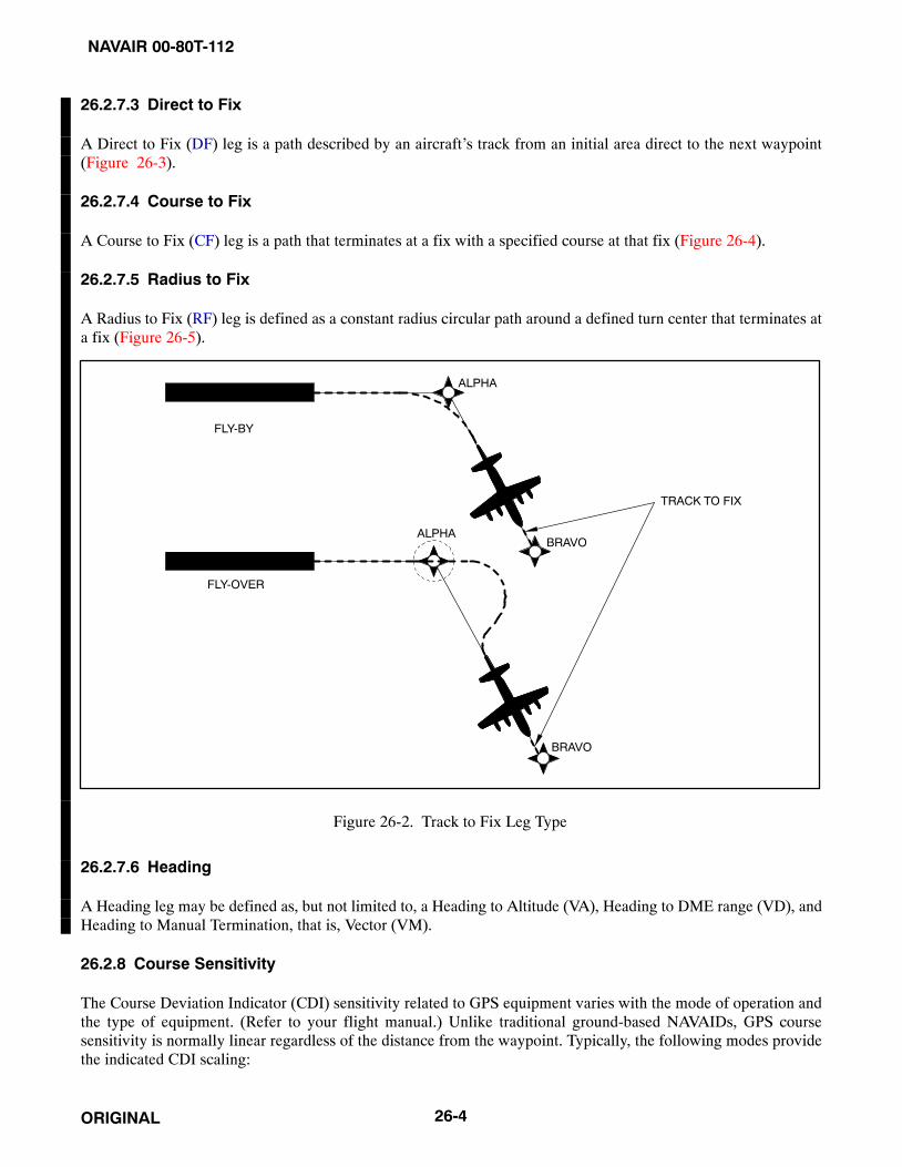
NAVAIR 00-80T-112
ORIGINAL 26-4
26.2.7.3 Direct to Fix
A Direct to Fix (DF) leg is a path described by an aircraft’s track from an initial area direct to the next waypoint(Figure 26-3).
26.2.7.4 Course to Fix
A Course to Fix (CF) leg is a path that terminates at a fix with a specified course at that fix (Figure 26-4).
26.2.7.5 Radius to Fix
A Radius to Fix (RF) leg is defined as a constant radius circular path around a defined turn center that terminates ata fix (Figure 26-5).
FLY-BY
FLY-OVER
ALPHA
BRAVO
BRAVO
ALPHA
TRACK TO FIX
Figure 26-2. Track to Fix Leg Type
26.2.7.6 Heading
A Heading leg may be defined as, but not limited to, a Heading to Altitude (VA), Heading to DME range (VD), andHeading to Manual Termination, that is, Vector (VM).
26.2.8 Course Sensitivity
The Course Deviation Indicator (CDI) sensitivity related to GPS equipment varies with the mode of operation andthe type of equipment. (Refer to your flight manual.) Unlike traditional ground-based NAVAIDs, GPS coursesensitivity is normally linear regardless of the distance from the waypoint. Typically, the following modes providethe indicated CDI scaling:

NAVAIR 00-80T-112
ORIGINAL26-5
26.2.8.1 En Route Mode
En route phase, prior to the execution of the instrument approach, the display sensitivity full-scale deflection is 1 timesthe RNP value either side of centerline. En route obstacle clearance area is based on the RNP value. Aircrews shallnot assume the primary protected containment for the route of flight en route is ±10 nm (refer to specific aircraftNATOPS or FMS user’s manual).
26.2.8.2 Terminal Approach Mode
Upon activation of the approach mode, the display sensitivity should smoothly transition from a full-scale deflectionof en route RNP to terminal RNP by 30 nm from the destination airport. Aircrew are reminded that the obstacleclearance area reduces as the RNP value transitions from en route to terminal. The approach mode must be active toproceed past the final approach fix on a nonprecision approach.
FLY-OVER WP
BRAVO
ALPHA
DIRECT TO FIX LEG
Figure 26-3. Direct to Fix Leg Type

NAVAIR 00-80T-112
ORIGINAL 26-6
COURSE 150
ALPHA
Figure 26-4. Course to Fix Leg Type
BRAVOALPHAARC CENTER POINT
Figure 26-5. Radius to Fix Leg Type

NAVAIR 00-80T-112
ORIGINAL26-7
26.2.8.3 Final Approach Mode
At a distance of 2 nm inbound to the Final Approach Fix (FAF) waypoint, the display sensitivity begins to transitionto a full-scale deflection of 0.3 nm either side of centerline. Some GPS avionics may provide an angular displaybetween the FAF and Missed Approach Point (MAP) that approximates the course sensitivity of the localizer portionof an Instrument Landing System (ILS).
26.2.8.4 Missed Approach Mode
When navigation to the missed approach holding point is activated, the CDI display sensitivity transitions back toterminal area sensitivity (±1 nm).
26.2.9 Navigation Database
Navigation databases supporting GPS equipment certified for en route and terminal operations contain, as aminimum, all airports, VORs, VORTACs, Non-Directional Beacons (NDBs), and all named waypoints andintersections shown on en route and terminal area charts, Standard Instrument Departures (SIDs), and StandardTerminal Arrivals (STARs).
In the terminal area, the database will include waypoints for SIDs and STARs as well as other flight operations fromthe beginning of a departure to the en route structure or from an en route fix to the beginning of an approach procedure.All named waypoints are identified with a five-letter alpha character name provided by the National Flight DataCenter (NFDC). Waypoints unnamed by the NFDC, such as a DME fix, are assigned a five-letter alphanumeric codedname in the database. (As an example, D234T — This coded waypoint represents a point located on the 234 radialof XYZ VORTAC at 20 nm. The letter T is the twentieth letter of the alphabet and is used to indicate a distance of20 nm.)
26.3 RESTRICTIONS ON THE USE OF GPS
26.3.1 Specific Capabilities and Restrictions
Specific GPS equipment capabilities vary widely from aircraft to aircraft; therefore, all pilots must be thoroughlyfamiliar with the GPS equipment installed in their aircraft, its authorized use, and its limitations. Some USN aircraftare not capable of performing all of the activities described in this chapter. Aircrews must consult OPNAV 3710.7series, this manual, wing directives, and the aircraft NATOPS manual to fully determine the capabilities of the aircraftGPS equipment and restrictions on its use. As per OPNAV 3710.7 series, hand-held GPS receivers shall not be usedfor instrument navigation.
26.3.2 Use of GPS Outside of the U.S. National Airspace System (NAS)
GPS use may be further restricted depending on the area of operation. Flight using GPS is not authorized in somecountries. If you plan to use GPS outside the National Airspace System (NAS), check for additional restrictions inFlight Information Publications (FLIP) General Planning (GP) and Area Planning (AP) documents in your area ofintended operation. The aircrew shall ensure all non-DoD-approved approaches flown outside the U.S. and Canadausing GPS for primary navigation are approved by the Naval Flight Information Group (NAVFIG).
26.3.3 Receiver Autonomous Integrity Monitoring (RAIM)
GPS equipment certified for Instrument Flight Rules (IFR) use must have the capability of verifying the integrity ofthe signals received from the GPS constellation. Loss of satellite reception and Receiver Autonomous IntegrityMonitoring (RAIM) warnings may occur due to aircraft dynamics (changes in pitch or bank angle). Antenna locationon the aircraft, satellite position relative to the horizon, and aircraft attitude may also affect reception of one or more

NAVAIR 00-80T-112
ORIGINAL 26-8
satellites. As the relative positions of the satellites are constantly changing, prior experience with the airport does notguarantee reception at all times, and RAIM availability should always be checked. The integrity of the GPS signalis verified by determining if the integrity solution is out of limits for the particular phase of flight, if a satellite isproviding corrupted information, or if there is an insufficient number of satellites in view. When the integrity of theGPS information does not meet the integrity requirements for the operation being performed, the aircraft GPSavionics will provide a warning in the cockpit. A GPS integrity warning in the cockpit is equivalent to an OFF flagon your Horizontal Situation Indicator (HSI); your GPS navigation information may no longer be reliable. Refer tothe aircraft NATOPS for specific information regarding your GPS avionics.
26.3.4 Database Requirements
To use GPS for IFR navigation in the terminal area or for GPS nonprecision approaches, the aircraft GPS equipmentmust include an updatable navigation database. GPS airborne navigation databases may come from the NationalGeospatial-Intelligence Agency (NGA) via the mission planning system or from an approved commercial source.
26.3.4.1 Manual Database Manipulation
Manual entry/update of the validated data in the navigation database is not possible; however, this requirement doesnot prevent the storage of user-defined data within the equipment.
26.3.5 RNAV in the Terminal Area
Some GPS equipment will provide the capability to use RNAV procedures in the terminal area. Using GPS equipmentas the primary navigation source for RNAV in the terminal area is only permitted if all of the waypoints defining theroute of flight can be retrieved from the aircraft GPS navigation database. GPS primary-source navigation usinguser-defined waypoints may not be used after the Initial Approach Fix (IAF) or prior to the termination point of a SID.GPS equipment may be used to identify the IAF on Instrument Approach Procedures (IAPs) and the termination pointon SIDs.
26.3.6 GPS Approach Restrictions
There are several important operating restrictions when using GPS to fly approaches.
26.3.6.1 Database Restrictions
Instrument approaches must be accomplished in accordance with approved instrument approach procedures that areretrieved from the FMS database using the current update cycle.
Aircrew should not manually adjust designed RNP values (retrieved fromdatabase), unless operational requirements dictate. Aircrew shall not usemanual RNP values in terminal mode of flight. RNP values other thanstandard RNP will be noted on the terminal procedure. Failure to adhere todesign RNP values (retrieved from database) in the terminal mode mayresult in a flight violation or mishap.
26.3.6.2 Integrity Monitoring
Instrument approaches must be conducted in the FMS Approach mode, and GPS integrity monitoring (RAIM) mustbe available at the final approach fix, as indicated to the pilot by the INTG annunciator being extinguished.

NAVAIR 00-80T-112
ORIGINAL26-9
26.3.6.3 Alternate Navigation Equipment
The aircraft must have other approved navigation equipment installed and functioning appropriate for the route tothe destination airport and any required alternate. Ground-based facilities necessary for these routes must also beoperational. GPS-overlay and GPS stand-alone approaches may be flown without the need to tune, ident, or monitorany other NAVAID (though this is not recommended).
26.3.6.3.1 RNAV Procedural Speed Restrictions
Some arrival and departure procedures will have speed restrictions on a specific segment(s) or the entire procedure.These restrictions ensure the aircraft remains within the obstacle clearance area or has proper track stabilization priorto the next programmed waypoint.
26.3.6.4 Scaling and Alerting
The GPS navigation system used for the approach shall use scaling and alerting criteria no less restrictive thanRNP 0.3 prior to continuing past the final approach fix. The RNP criteria shall remain for the entire approach.
26.3.6.5 Multiple GPS Receivers
On aircraft equipped with multiple (installed) GPS receivers the aircrew shall use the integrity function for the GPSreceiver being used for navigation. The integrity function of other installed GPS (SPS or PPS) receivers shall not beused to indicate the integrity of the GPS receiver being used for navigation.
26.3.7 Alternate Airport Restrictions
When an alternate airport is required, it must be served by an approach based on other-than-GPS navigation, theaircraft must have operational equipment capable of using that navigation aid, and the required navigation aid mustbe operational.
26.4 GPS APPROACH NOMENCLATURE
26.4.1 GPS Stand-Alone Approaches
GPS stand-alone approaches are constructed specifically for use by GPS and do not have a traditional underlyingprocedure. GPS stand-alone approaches are identified by the absence of other NAVAIDs in the approach title (e.g.,GPS RWY 35). Current stand-alone approaches will be renamed over time as RNAV (GPS) approaches (e.g., RNAVRWY [GPS] 35). The Straight-In Minimums on current GPS charts correspond to the Lateral Navigation (LNAV)Minimums on RNAV charts.
26.4.2 GPS Overlay Approaches
GPS overlay approaches permit pilots to use GPS avionics under IFR to fly existing instrument approach procedures.Overlay approaches can be identified by the use of “GPS” in the title (e.g., “VOR or GPS RWY 24”).
26.4.2.1 GPS Not in the Title
Some approaches (typically VORs and NDBs) do not have GPS in the title, yet they are coded into the aeronauticaldatabase used by the GPS and are retrievable. These approaches do not qualify as “overlay” approaches, since “ORGPS” is not in the title. They can, however, be used as a situational awareness tool to back up the pilot at the controlswhile flying a conventional approach.

NAVAIR 00-80T-112
ORIGINAL 26-10
26.4.3 RNAV (GPS) Approaches
The GPS “Stand-alone” and GPS “Overlay” approaches are being replaced by the RNAV (GPS) approach format.The RNAV (GPS) format is known as a performance-based procedure. The RNP accuracy required to fly theseapproaches is RNP 0.3. The minimums section is broken down into sections of LNAV, LNAV/Vertical Navigation(VNAV), Localizer Performance with Vertical Guidance (LPV), and GNSS Landing System (GLS). The LNAVapproaches generally (but not always) have the highest minimums and are flown to a Minimum Descent Altitude(MDA) much like a traditional VOR or Tactical Air Navigation (TACAN). The LNAV/VNAV section of theminimums designates the Decision Altitude (DA) and visibility for aircraft approved for Barometric VerticalNavigation (BARO-VNAV). The LPV section of the minimums designates the Decision Altitude for equipmentperforming to the level of Wide Area Augmentation System (WAAS) specifications. The GLS section of theminimums is currently designated “N/A” as a placeholder for the GLS. LPV is the only system authorized to occupythe GLS line.
26.4.4 RNAV (RNP) Approaches
The latest addition to the GPS approach family is the RNAV (RNP) approach also known as Special Aircraft andAircrew Authorization Required (SAAAR). These approaches are commonly used to avoid prohibited areas, terrain,and noise-sensitive areas that require certified aircraft and specific aircrew training. The RNP level required variesfrom RNP 0.11 to RNP 0.15 to RNP 0.3. The Naval Flight Information Group is developing SAAAR approaches ona limited basis for Navy and Marine Corps installations.
26.5 AIRCREW ACTIONS
26.5.1 Preflight
In addition to being intimately familiar with operation of their GPS equipment, pilots need to accomplish severaladditional actions prior to flight using GPS.
26.5.1.1 Check NOTAMs
Review Notices to Airmen (NOTAMs) by referring to the installation NOTAMs for your destination and anyalternates. GPS satellite outages are issued as GPS NOTAMs using Pseudo Random Noise (PRN) number or SatelliteVehicle Number (SVN) and can be accessed using the identifier KGPS. It is important to deselect the affected satelliteon your FMS/GPS. This ensures the particular satellite deselected is not used for the navigation solution, RAIMcalculations, or RAIM prediction.
Receiver manufacturers and/or database suppliers may supply “NOTAM” type information concerning databaseerrors. Pilots should check these sources, when available, to ensure that they have the most current informationconcerning their electronic database.
26.5.1.2 File the Appropriate Equipment Suffix
Aircraft navigating using GPS are considered to be RNAV-equipped aircraft and the appropriate equipment suffixshould be included on the flight plan.
26.5.1.3 GPS Equipment Checks
Check GPS ground equipment by following the specific startup and self-test procedures for the GPS receiver or FMSas outlined in the aircraft NATOPS manual. Check the currency of your database and predicted RAIM available statusfor the approach you plan to fly at your Estimated Time of Arrival (ETA).
26.5.2 Terminal Area Operations and Departure
26.5.2.1 Load SID
If a SID is to be flown, load the appropriate SID by retrieving the route from the navigation database. If the SID cannotbe retrieved from the database, then you may not use RNAV procedures to fly it prior to the SID termination point.

NAVAIR 00-80T-112
ORIGINAL26-11
26.5.2.2 Terminal Sensitivity
When flying a SID using GPS, the pilot must ensure the terminal sensitivity mode is selected to ensure the correctscaling of the CDI (±1 nm).
26.5.3 En Route Operations
26.5.3.1 Use of Predictive Integrity
While you are en route to your destination, check the expected integrity (RAIM availability) for the planned approach.If your check indicates the appropriate integrity for the planned operation may not be available, develop an alternateplan for landing at the airfield or proceed to your alternate.
26.5.4 Prior to Descent
26.5.4.1 GPS Approach Briefing
Thoroughly brief the entire GPS instrument approach procedure including the missed approach instructions.Compare the approach retrieved from the GPS navigation database to the instrument approach procedure publishedon your approach plate. Should differences between the approach chart and database arise, the published approachchart, supplemented by NOTAMs, takes precedence.
26.5.4.2 Develop a Backup Plan
Develop a backup plan to use in case of GPS or GPS integrity failure. Pay particular attention to ground-basedNAVAIDs, which can be used to help maintain position awareness. Be sure to consider the possibility of equipmentfailure past the FAF.
26.5.4.3 Load STAR
If a STAR is to be flown, load the appropriate STAR by retrieving the route from the navigation database. If the STARcannot be retrieved from the database, then you may not use RNAV procedures to fly the procedure. Additionally,terminal area routing that cannot be retrieved from the navigation database may not be used.
26.5.5 Terminal Area Operations and Arrival
26.5.5.1 Maintain Situational Awareness
As you prepare to enter the busy environment of the terminal area, it is important to maintain a high level of situationalawareness using all available means. Monitor all ground-based NAVAIDs that are available to you (bearing pointers,DME, etc.), as GPS approaches are flown point to point. With GPS selected, the bearing pointer on your HSI anddistance measurement (DME readout) may be to the next waypoint, not necessarily to the field.
26.5.6 Be Prepared to Use Traditional NAVAIDs
Experience has shown situational awareness can deteriorate when flying GPS approaches if the sequence of eventsdoes not go as planned. Be prepared to go to your backup plan if you become disoriented while flying the GPSapproach.
26.5.6.1 Be Wary of “Heads-Down”
Operating with GPS in the terminal area tends to be more “heads-down” than normal, especially when things do notgo as planned. Being intimately familiar with your GPS equipment and thoroughly preparing for the approach willallow you more time to clear for other traffic.
NAVAIR 00-80T-112
ORIGINAL 26-12
26.5.6.2 GPS is a New Form of Flying
Flying GPS approaches involves a new way of flying for most military pilots. Setting up a GPS receiver for anapproach usually involves many more operations than are required to configure traditional navigation equipment. Thesequence of events is critical to success. Setup routines are not always intuitive, requiring pilots to be thoroughlyfamiliar with their equipment before flying GPS approaches in Instrument Meteorological Conditions (IMC). Oncethe equipment is properly configured for the approach, the GPS-based approach is much easier and safer to fly thana terrestrial-based (e.g., VOR, TACAN, etc.) nonprecision approach.
26.5.7 Approach Procedures
Flying a GPS approach is much like flying any other nonprecision approach. For procedures regarding equipmentspecifics and setup, reference NATOPS and your FMS/GPS Operator’s Manual. Incorrect inputs into the GPSreceiver are especially critical during approaches. In some cases, an incorrect entry can cause the receiver to leavethe approach mode.
26.5.7.1 Prior to the IAF
Some GPS equipment will automatically “Arm” once the aircraft is within 30 nm from the airfield. Other equipmentwill present a pilot selectable function when within 30 nm that requires the pilot to “Arm” the approach (refer to thespecific aircraft NATOPS). If manual arming is required by the equipment, then the aircrew shall “Arm” the approachmode prior to the IAF. Arming the approach mode will allow your GPS equipment to automatically change from enroute RNP to terminal RNP.
26.5.7.1.1 Inside of 30 nm
If you do not arm the approach mode prior to 30 nm from the airport, your GPS equipment will generate a warningonce your aircraft is 30 nm from the airport. If the system automatically arms, there will be no annunciation at 30 nm.
26.5.7.1.2 3 nm Prior to the FAF
Approximately 3 nm prior to the FAF, your equipment will alert you that display sensitivity is about to change again.At 3 nm, if you still have not armed the approach mode, it will give you another warning.
26.5.7.1.3 Ramp Down
Beginning 2 nm prior to the FAF, your equipment will (if previously armed) automatically scale from terminalintegrity performance (±1 nm) to approach integrity performance (±0.3 nm). This change in sensitivity is calledramping down, and depending on your equipment, will occur between 2 nm prior to the FAF and the FAF. Afterramping down, the equipment is considered to be in approach mode.
Aircrew must ensure the equipment has switched from the armed mode tothe active mode by the time the aircraft reaches the FAF. Aircrew shall notdescend below the FAF altitude unless the equipment is in approach mode.The aircraft may not remain within primary obstacle clearance area of theinstrument approach procedure. Transition to your backup approach (ifavailable) or proceed to the MAP along the final approach course andexecute the missed approach or comply with ATC instructions.

NAVAIR 00-80T-112
ORIGINAL26-13
CAUTION
Failure to ramp down to approach mode may be an indication of integrityfailure, failure to arm, the aircraft did not enter the capture gate, or someother type of failure.
26.5.7.1.4 Two Nautical Mile (2 nm) Lockout
At 2 nm, if you still have not armed the approach mode, your equipment will not let you fly the approach. Yourequipment will flag, and GPS navigation guidance will not be provided beyond the FAF.
26.5.7.1.5 GPS Integrity Warning Prior to FAF
If a GPS integrity warning occurs prior to the FAF, the pilot should not descend to the MDA, but should proceed tothe MAP via the FAF, perform a missed approach, and notify ATC as soon as practical. Alternatively, the pilot maycontinue, provided a backup approach is available using another approved source of navigation.
26.5.7.2 Final Approach
The inbound course displayed on the GPS between the FAF and the MAP may be slightly different than that printedon the approach chart and should not affect approach performance. This is due to the way the GPS connects theapproach waypoints.
26.5.7.2.1 Stepdown Waypoints
Stepdown waypoints in the final approach segment of RNAV (GPS) approaches are named in addition to beingidentified by Along Track Distance (ATD). Most RNAV avionics currently do not accommodate waypoints betweenthe FAF and MAP. Stepdown waypoints may not appear in the sequence of waypoints in the navigation database.Aircrew can determine the location of stepdown waypoints and visual descent points (if published) by using ATD.
26.5.7.2.2 GPS Integrity Warning After the FAF
A GPS integrity warning occurring after the FAF is a serious situation and pilots must be prepared to take immediateaction. Transition to your backup approach (if available) or proceed to the MAP along the final approach course andexecute the missed approach via the route and altitudes specified in the published missed approach procedure orcomply with ATC instructions.
26.5.7.3 Performing the Published Missed Approach Procedure
26.5.7.3.1 Missed Approach Point (MAP)
The designated MAP will vary depending on the type of approach minimums selected. The MAP for LNAV will bethe runway threshold or a named waypoint. The MAP for LNAV/VNAV will be at the published DA.
26.5.7.3.2 Select Missed Approach Mode
At the MAP, most equipment will not automatically sequence to the next required waypoint; therefore, the pilot mustmanually sequence the GPS equipment to the next waypoint (refer to specific aircraft NATOPS).
26.5.7.3.3 Performing the Missed Approach
If the missed approach is initiated prior to the MAP, proceed to the MAP along the final approach course and thenvia the route and altitudes specified in the published missed approach procedure or comply with ATC instructions.If the missed approach procedure includes a turn, do not begin the turn prior to the MAP. The obstacle clearance areaprovided for the missed approach is predicated upon the missed approach being started at the MAP.

NAVAIR 00-80T-112
ORIGINAL 26-14
NoteThe GPS/FMS may or may not provide proper guidance along the missedapproach path; therefore, it is imperative to review the missed approachprocedure fully prior to flying it.
26.5.7.3.4 Missed Approach Climb Gradient
Regardless of the method used to navigate the missed approach procedure, the pilot is still responsible for terrain andobstacle avoidance as well as any ATC-required climb gradients. In order to avoid obstacles, pilots must plan to climbat a minimum gradient of 200 feet per nm unless a higher gradient is published.
26.6 GPS NAVIGATION TRAINING
26.6.1 General
Aircrew should practice GPS approaches under Visual Flight Rules (VFR) until thoroughly proficient with all aspectsof their equipment (receiver and installation) prior to attempting flight under IFR in IMC. Many GPS receiversprovide a simulation mode that can be used to become familiar with receiver operations prior to actual flightoperations. Proper training of GPS navigation in controlled airspace will enhance safety and awareness when usingPPS for combat operations. GPS training will be developed, with assistance from Naval Air Systems CommandPMA-170, by the respective TYCOM/FRS/Type Wing.
26.6.2 Ground Instruction
The use of GPS for flight in controlled airspace requires a thorough knowledge of the terms and nomenclature usedto describe and depict GPS navigation processes. The charting of GPS procedures does not follow the conventiondescribed by previous training. Some of the areas that GPS training should cover are:
1. The meaning and proper use of Aircraft Equipment/Navigation Suffixes.
2. Procedure characteristics as determined from chart depiction and textual description.
a. Depiction of waypoint types (fly-over and fly-by) and path terminators as well as associated aircraft flightpaths.
b. Published material for RNAV routes, SIDs, STARs, and GPS approaches.
3. Utilizing the RAIM prediction function.
4. RNAV/GPS system-specific information.
a. Levels of automation, mode annunciations, changes, alerts, interactions, reversions, and degradation.
b. Functional integration with other aircraft systems.
c. The meaning and appropriateness of route discontinuities as well as related flightcrew procedures.
d. Monitoring procedures for each phase of flight (e.g., monitor PROG or LEGS page).
e. Types of navigation sensors (e.g., IRU, EGI, GEM, MAGR2K) utilized by the RNAV system and associatedsystem prioritization/weighting/logic.
f. Turn anticipation with consideration to speed and altitude effects.

NAVAIR 00-80T-112
ORIGINAL26-15
g. Interpretation of electronic displays and symbols.
h. Verify currency of aircraft navigation data.
i. Verify successful completion of RNAV system self-tests.
5. Crew coordination and FMS/CDU etiquette.
6. Using the FMS/CDU/displays to maximize situational awareness.
7. Using the FMS/CDU for visual approaches.
8. Extending a point for interception.
9. Intercepting a route between two points.
10. Conditional waypoints and FMS-generated waypoints.
26.6.3 GPS Navigation Flight Training
The amount and type of flight training should be sufficient to expose the flightcrew to the displays, autopilot use (ifapplicable), and aircraft performance when using GPS for navigation.
1. Proceeding direct to a waypoint in the flight plan and not in the flight plan.
2. Inserting an instrument Departure Procedure (DP) into the flight plan, including setting terminal CDIsensitivity, if required, and the conditions under which terminal RAIM is available for departure.
3. Inserting the destination airport in a flight plan.
4. Determining the correct IAF to proceed to when entering a Terminal Arrival Area (TAA) and determining thecorrect altitudes within a TAA.
5. Executing overlay approaches (especially procedure turns and arcs).
6. Changing to another approach after selecting an approach.
7. Executing “direct” missed approaches where the route is direct to the first waypoint after the MAWP.
8. Executing “routed” missed approaches where the route is not direct to a waypoint from the MAWP, particularlywhere a course must be manually inserted and flown. This procedure may vary with installation of the receiver.
9. Entering, flying, and exiting holding patterns “manually” (e.g., non-charted holding, holding following aprocedure turn, and holding with a second waypoint in the holding pattern).
10. Flying a “route” from a holding pattern.
11. Executing an approach with radar vectors to the final segment.
12. Actions required for RAIM failure both before and after the Final Approach Waypoint (FAWP).
13. Programming a radial and distance from a VOR.
14. Recovering from sequencing past a waypoint at which holding was intended.

NAVAIR 00-80T-112
ORIGINAL 26-16
15. Operator-recommended levels of automation for phase of flight and workload, including methods to minimizecross-track error to maintain procedure centerline.
16. Crew coordination and FMS/CDU etiquette.
17. Using the FMS/CDU to maximize situational awareness.
18. Using the FMS/CDU for visual approaches.
19. Extending a point for interception.
20. Intercepting a route between two points.
21. Conditional waypoints and FMS-generated waypoints.
26.7 FUTURE IMPROVEMENTS TO GPS
26.7.1 Wide Area Augmentation System (WAAS)
The Wide Area Augmentation System (WAAS) is a critical component of the FAA strategic objective of a seamlesssatellite navigation system for civil aviation. This system will improve the accuracy, availability, and integrity of GPS,thereby improving the capacity and safety currently provided by the National Airspace System. Ultimately, WAASwill allow GPS to be used as a primary means of navigation from takeoff through Category I precision approach.WAAS will provide vertical guidance procedures to achieve an operational capability similar to an instrument landingsystem, where suitable airport conditions exist.
Unlike traditional ground-based navigation aids, WAAS will cover a more extensive service area. Wide-Area GroundReference Stations (WRSs) have been linked to form a U.S. WAAS network. Signals from GPS satellites are receivedby these precisely surveyed ground reference stations and any errors in the signals are identified. Each station in thenetwork relays the data to one of two Wide-Area Master Stations (WMSs), where correction information for specificgeographical areas is computed. A correction message is prepared and uplinked to a geostationary communicationssatellite (GEO) via a Ground Uplink Station (GUS). This message is broadcast on the same frequency as GPS (L1,1575.42 MHz) to future GPS/WAAS receivers onboard aircraft flying within the broadcast coverage area of WAAS.Other modes of transportation also benefit from the increased accuracy, availability, and integrity that WAAS willdeliver. The WAAS broadcast message improves GPS signal accuracy from 100 meters to approximately 7 meters.Planned expansion of the U.S. network will include Canada, Iceland, Mexico, and Panama, and has the potential toexpand to other countries as well. Additionally, Japan and Europe are building similar systems that are planned tobe interoperable with the U.S. WAAS. The merging of these systems will create a worldwide seamless navigationcapability similar to GPS, but with greater accuracy, availability, and integrity.
On March 7, 2006, the FAA declared that WAAS was performing to the level necessary to allow approaches to 200feet DA. WAAS has provided coverage to 99 percent of the continental U.S. and has an availability rate of 99.87percent. The FAA is commissioning 300 approaches per year that are WAAS capable. The addition of WAAScapability will be shown in the minimums section of the approach chart as “LPV.” The LPV minimums shall onlybe flown by properly certified aircraft.
NAVAIR 00-80T-112
ORIGINAL26-17/(26-18 blank)
26.7.2 Local Area Augmentation System (LAAS)
The Local Area Augmentation System (LAAS) will augment the Global Positioning System to provide an all-weatherapproach, landing, and surface navigation capability. LAAS focuses its service on a local area (approximately a 20to 30 mile radius), such as an airport, and broadcasts its correction message via a Very High Frequency (VHF) radiodata link from a ground-based transmitter. LAAS will have a profound impact on aviation navigation. LAAS willyield the extremely high accuracy, availability, and integrity necessary for Category I, II, and III precision approaches.It is expected that the end-state configuration will pinpoint the aircraft position to within one meter or less with asignificant improvement in service flexibility and user operating costs. Curved approach paths, not possible usingthe current instrument landing systems, will be possible for Category I, II, and III precision approaches. Approacheswill be designed to avoid obstacles, restricted airspace, noise-sensitive areas, or congested airspace. Unlike currentlanding systems, LAAS will provide multiple precision approach capabilities to runways within the LAAS coveragearea. Duplication of equipment solely for the purpose of serving multiple runways can be eliminated. Also, airportswith the need for precise surface area navigation may use the accuracy of LAAS for the position determination ofaircraft. Using this capability, controllers will know the location of all airport service vehicles and taxiing aircraft toassist in the prevention of runway incursions in low visibility conditions. Furthermore, aircraft operators will benefitfrom the reduction of expenses associated with purchasing a variety of radio navigation equipment. Potentially,WAAS and LAAS could use the same aircraft avionics to accomplish both the WAAS and LAAS missions, reduceavionics maintenance costs, and realize savings in aircrew training.
The FAA has already successfully demonstrated the feasibility of GPS-based Category III precision approaches andhas completed the proposed architecture for LAAS. This architecture was successfully presented and approved bythe International Civil Aviation Organization (ICAO) Global Navigation Satellite System (GNSS) Panel in February1997. To ensure LAAS will be compatible with international standards, participation in the International CivilAviation Organization (ICAO) Global Navigation Satellite System Panel (GNSS-P) has been ongoing. Initial FAACategory I LAAS is scheduled to be operational by September 2003. Federal Category II/III development isscheduled to begin in FY03 with production in FY06. The FAA and the Government-Industry Partnership (GIP)partners will continue working toward a private/public use certified LAAS Category I system with the goal oftransitioning to the Federal Category I procurement as soon as possible.

NAVAIR 00-80T-112
ORIGINAL26-1/(26-2 blank)

NAVAIR 00-80T-112
ORIGINAL79/(80 blank)
PART VII
Instrument Flight
Chapter 27 — Flight Planning
Chapter 28 — Flight Clearance
Chapter 29 — En Route Procedures
Chapter 30 — Terminal Procedures

NAVAIR 00-80T-112
ORIGINAL1/(2 blank)

NAVAIR 00-80T-112
ORIGINAL27-1
CHAPTER 27
Flight Planning
27.1 PREFLIGHT PREPARATION
Every pilot is required to obtain a preflight weather briefing, review all applicable Notices to Airmen (NOTAMs),and file a flight plan. The weather briefing should consist of the latest or most current weather, airport, and en routeNavigation Aid (NAVAID) information. Weather briefing services should be obtained at a DoD weather forecastingoffice. Weather minimums for naval aviators are defined in OPNAV 3710.7 series.
27.2 WEATHER BRIEFING, SUPPORT PRODUCTS, AND SEVERE WEATHER RESTRICTIONSAND PRODUCTS
Navy and Marine Corps Meteorology and Oceanography (METOC) activities are tasked with providing METOCsupport to the operating forces of the Navy and Marine Corps. These activities are equipped and staffed to providefull spectrum METOC support products to naval aviators.
27.2.1 Weather Briefing
Pilots are responsible for reviewing and being familiar with weather conditions for the area in which flight iscontemplated. Before obtaining a flight clearance, a pilot must receive a weather briefing where services areavailable; the briefing shall be conducted by a qualified meteorological forecaster. These briefings may be conductedin person, or when available, via weathervision, telephone, or by autographic means. Additionally, a DD Form 175-1(Flight Weather Briefing) shall be completed for all flights in accordance with OPNAVINST 3710.7 series.
Due to the perishable nature of meteorological data, and in an effort to ensure aviators have the most up-to-dateinformation, all weather briefings will be assigned a briefing void time. The briefing void time shall not exceed the“weather briefed” time by more than 3 hours, and it shall never exceed the planned departure time by more than30 minutes. This time may be extended when, in the opinion of the meteorologist, conditions are such that a reviewof the initial form and the deletion/addition of pertinent data is such that a formal rebriefing is not required. Whenextending void times, the rule stated above applies with the exception that the “weather rebriefed at” time is used asthe base time.
Flights departing after void time expiration are in violation of OPNAVINST 3710.7 series because, for recordpurposes, the briefing never took place, as the official record of the briefing is no longer valid. Requests for extensions,and proper planning, will eliminate this situation.
As a minimum, terminal forecasts entered on the DD Form 175-1 shall be valid for a period of 1 hour before, until1 hour after, the planned arrival time at destination(s) and alternates. In the event a pilot is departing from an airfieldwith no weather briefing facility, telephone briefings are available from both military and civilian facilities.Telephone numbers for military briefing facilities are listed in the Flight Information Publications (FLIP). Thesefacilities may be called collect. The pilot receiving a weather briefing must ensure all essential weather elements havebeen included and adequately covered in the briefing. Meteorological forecasters serve as advisors to the aviator;therefore, pilots should not hesitate to request clarification or additional information when doubt exists. The ease withwhich all-weather flights are completed successfully is directly proportional to the pilot’s preparation andunderstanding of the environment in which the flight operates.
27.2.2 Support Products
In addition to the DD Form 175-1, there are other weather-related products that are readily available to aviators thatactively support safe and successful mission accomplishment.

NAVAIR 00-80T-112
ORIGINAL 27-2
27.2.2.1 Optimum Path Aircraft Routing System (OPARS)
Optimum Path Aircraft Routing System (OPARS) is a service that combines the latest forecast environmental winddata fields with the most fuel-efficient flight profile for specific aircraft. A minimum of 2 to 3 hours is required forsubmission of OPARS requests and return receipt of the completed product. The OPARS product is constructedutilizing a database that contains aircraft performance characteristics, high-altitude airways, NAVAIDs, waypoints,all airports with runways of 5,000 feet or longer (in the Northern Hemisphere), and restricted area information. Theenvironmental database contains wind data from 1,000 to 53,000 feet out to 48 hours, which is updated every 12 hours.
A typical OPARS flight plan will contain summarized flight times and distances, takeoff and landing weight, as wellas time, distance, airspeed, groundspeed, and fuel usage between NAVAIDs. It will accept any mission with up to threelegs, along standard jet routes from NAVAID point to NAVAID point, rhumbline with checkpoints every 5� latitudeor longitude, or along great circle routes, and select the optimum path. The aviator selects these options before theflight plan is submitted. OPARS will route at the most efficient flight level, or between any upper and lower flightlevel. For further information on this program, refer to the Aviator’s Guide to OPARS Flight Planning (September1998), or contact the nearest Naval Oceanography Command Activity.
27.2.2.2 Flight Weather Packets
When available, pilots are encouraged to request a flight weather packet when contemplating extended flights,especially those flights that will be conducted on long overwater routes. As a minimum, in addition to aDD Form 175-1, these packets contain surface and upper air charts, a Horizontal Weather Depiction (HWD) chart,and, for overwater flights, altimeters and ditch headings. Additional charts/data tailored to meet special missionneeds, such as D values, OPARS data, etc., are also available. When considering the preparation time involved, andthe amount of data that must be accumulated and reviewed, every attempt should be made to give a minimum 2 hoursadvance notice for this product. While en route, pilots should make every attempt to validate the data contained inthe packet. Upon arrival at destination, the packet should be provided to the local weather activity for review andforwarding to the forecasting activity that prepared the packet.
27.2.3 Severe Weather Restrictions and Products
Whenever practical, flights shall be planned to circumvent areas of forecasted atmospheric icing and thunderstormactivity.
27.2.3.1 Aviation Severe Weather Watch Bulletins (WWs)
The National Weather Service (NWS) issues unscheduled Severe Weather Watch Bulletins (WWs) whenever thereis a high probability of severe weather. These WWs are issued for a designated area and for a specified time period.WWs are used by Naval Oceanography Command activities for forecasting hazardous flying conditions. Except foroperational necessity, emergencies, and flights involving all-weather research projects or weather reconnaissance,pilots shall not file into or through areas where the National Weather Service has issued a WW unless one of thefollowing exceptions applies:
1. Performance characteristics of the aircraft permit an en route flight altitude above existing or developing severestorms; or
2. Storm development has not progressed, as determined by a qualified meteorological forecaster, for the plannedroute. In such situations:
a. Visual Flight Rules (VFR) filing is permitted if existing and forecast weather for the planned route permitssuch flights.
b. Instrument Flight Rules (IFR) flight may be permitted if aircraft radar is installed and operative, thuspermitting detection and avoidance of isolated thunderstorms.
c. IFR flight is permissible in positive control areas if visual meteorological conditions can be maintained, thusenabling aircraft to detect and avoid isolated thunderstorms.

NAVAIR 00-80T-112
ORIGINAL27-3
NoteIn most cases, WWs are not issued specifically for immediate coastalwaters or adjacent oceanic areas; however, in some situations, the weatherassociated with the WW will also be present over said areas. When dealingwith such a situation, pilots should request evaluation of the maritime areaby a forecaster to ensure WW conditions are not present.
27.2.3.2 Military Weather Warning Advisories (MWWAs)
The U.S. Air Force issues these graphical advisories, which provide an estimate of the weather-producing potentialof existing airmasses. These advisories are used whenever a WW is not in effect, and they are also useful for planningpurposes. MWWAs are posted in all Naval Weather Offices. A MWWA Bulletin that forecasts severe weather doesnot constitute a WW.
27.2.3.3 Significant Meteorological Information (SIGMETs) and Airmen’s MeteorologicalInformation (AIRMETs)
These advisories are prepared by the National Weather Service and broadcast by Flight Service Stations (FSSs) onVHF Omnidirectional Range (VOR) facilities.
27.2.3.3.1 SIGMETs
These advisories include weather phenomena potentially hazardous to all categories of aircraft. SIGMETs fall undertwo categories: convective and nonconvective.
27.2.3.3.2 Convective SIGMETs
Since thunderstorms are the reason for issuing convective SIGMETs, severe or greater turbulence, severe icing, andlow-level windshear associated with thunderstorm activity are implied. The criteria for issuing convective SIGMETsare as follows:
1. Tornadoes.
2. Line of thunderstorms.
3. Embedded thunderstorm(s).
4. Thunderstorm areas greater than or equal to thunderstorm intensity level 4 with an area coverage of 4/10 (40percent) or more.
5. Hail equal to or greater than 3/4 inch diameter.
Three convective SIGMET bulletins specifying Eastern (E), Central (C), and Western (W) U.S. will be issued, whenrequired, on a scheduled basis hourly at 55 minutes past the hour, and as specials on an unscheduled basis. They arevalid for 1 to 2 hours. It should be noted that although Air Route Traffic Control Centers (ARTCCs) may not givethe content of SIGMETs, they do alert IFR traffic that one is being broadcast and provide the identification of theNAVAID to monitor.
27.2.3.3.3 Nonconvective SIGMETs
The criteria for issuing nonconvective SIGMETs are as follows:
1. Severe and extreme turbulence.
2. Severe icing.
3. Widespread duststorms/sandstorms that lower visibility to less than 3 miles.

NAVAIR 00-80T-112
ORIGINAL 27-4
27.2.3.3.4 AIRMETs
These advisories will only be issued to amend an Aviation Area Forecast (FA) and relate to weather phenomena thatmay be potentially hazardous to aircraft concerning the following:
1. Moderate icing.
2. Moderate turbulence.
3. Sustained winds of 30 knots or more at the surface.
4. Widespread areas of ceilings less than 1,000 feet and/or visibility less than 3 miles.
5. Extensive mountain obscurement.
It should be noted that if the above phenomena are adequately forecast in the FA, an AIRMET will not beissued.
Applicable NOTAMs must be checked before every flight for your departure field, destination, possible alternates,and the airspace in between. NOTAM information is available from the U.S. NOTAM System (USNS) via theDefense Internet NOTAM Distribution System (DINS). Further explanation and definitions for all seven types ofNOTAMs can be found in the Aeronautical Information Manual (AIM).
File the DD-175 with the clearing authority at least 30 minutes prior to Estimated Time of Departure (ETD) inaccordance with OPNAV Instruction 3710.7 series and FLIP. If departing from a civil field, follow the procedureoutlined in FLIP. Weight and balance form and passenger manifest, if required, will be submitted with the flight plan.Instructions for completing the Federal Aviation Administration (FAA) Form 7233-1 flight plan can be found in theAIM.
Pilots shall use only the latest issue of aeronautical charts in planning and conducting flight operations. Aeronauticalcharts are revised and reissued on a regular scheduled basis to ensure that depicted data are current and reliable. Inthe conterminous U.S., Sectional Charts are updated every 6 months, IFR En Route Charts every 56 days, andamendments to civil IFR Approach Charts are accomplished on a 56-day cycle with a change notice volume issuedon the 26-day midcycle. Charts that have been superseded by those of a more recent date may contain obsolete orincomplete flight information.
FAA by 14 Code of Federal Regulations (CFR) Part 93, Subpart K, has designated High Density Traffic Airports(HDTAs) and has prescribed air traffic rules and requirements for operating aircraft (excluding helicopter operations)to and from these airports.
In addition to the filing of a flight plan, if the flight will traverse or land in one or more foreign countries, it isparticularly important that pilots leave a complete itinerary with someone directly concerned and keep that personadvised of the flight progress.
27.3 FOLLOW IFR PROCEDURES EVEN WHEN OPERATING VFR
To maintain IFR proficiency, pilots are urged to practice IFR procedures whenever possible, even when operatingVFR.
Simulated IFR flight is recommended (under the hood); however, pilots are cautioned to review and adhere to therequirements specified in 14 CFR Section 91.109 before and during such flight.
When flying VFR at night, in addition to the altitude appropriate for the direction of flight, pilots should maintainan altitude that is at or above the Minimum En Route Altitude (MEA) as shown on charts. This is especially true inmountainous terrain, where there is usually very little ground reference. Do not depend on your eyes alone to avoidrising unlighted terrain, or even lighted obstructions such as TV towers.
NAVAIR 00-80T-112
ORIGINAL27-5
27.3.1 Flight Plan — VFR Flights
Except for operations in or penetrating a Coastal or Domestic Air Defense Identification Zone (ADIZ) or DistantEarly Warning Identification Zone (DEWIZ), a flight plan is not required by the FAA for VFR flight. Localrequirements may differ.
It is strongly recommended that a flight plan (for a VFR flight) be filed. This will ensure you receive VFR Searchand Rescue Protection.
On pilot’s request, at a location having an active tower, the aircraft identification will be forwarded by the tower tothe FSS for reporting the actual departure time for the military arrival notification.
Although position reports are not required for VFR flight plans, periodic reports to FAA FSSs along the route are goodpractice. Such contacts permit significant information to be passed to the transiting aircraft and also serve to checkthe progress of the flight should it be necessary for any reason to locate the aircraft.
Pilots not operating on an IFR flight plan and when in level cruising flight are cautioned to conform with VFR cruisingaltitudes appropriate to the direction of flight.
When filing VFR flight plans, indicate aircraft equipment capabilities by appending the appropriate suffix to aircrafttype in the same manner as that prescribed for IFR flight.
27.3.2 Flight Plan — Defense VFR (DVFR) Flights
VFR flights into a Coastal or Domestic ADIZ/DEWIZ are required to file Defense VFR (DVFR) flight plans forsecurity purposes. Detailed ADIZ procedures are found in the AIM, National Security and Interception Procedures.(See 14 CFR Part 99.)
27.3.3 Composite Flight Plan (VFR/IFR Flights)
Flight plans that specify VFR operation for one portion of a flight, and IFR for another portion, are referred to asComposite Flight Plans. If VFR flight is conducted for the first portion of the flight, pilots should report their departuretime to the FSS with whom the VFR/IFR flight plan was filed and, subsequently, close the VFR portion and requestAir Traffic Control (ATC) clearance from the FSS nearest the point at which change from VFR to IFR is proposed.Regardless of the type facility with which you are communicating (FSS, center, or tower), it is the pilot’sresponsibility to request that facility to “CLOSE VFR FLIGHT PLAN.” The pilot must remain in VFR weatherconditions until operating in accordance with the IFR clearance.
When a flight plan indicates IFR for the first portion of flight and VFR for the latter portion, the pilot will normallybe cleared to the point at which the change is proposed. After reporting over the clearance limit and not desiring furtherIFR clearance, the pilot should advise ATC to cancel the IFR portion of the flight plan. Then, the pilot should contactthe nearest FSS to activate the VFR portion of the flight plan. If the pilot desires to continue the IFR flight plan beyondthe clearance limit, the pilot should contact ATC at least 5 minutes prior to the clearance limit and request further IFRclearance. If the requested clearance is not received prior to reaching the clearance limit fix, the pilot will be expectedto enter into a standard holding pattern on the radial or course to the fix unless a holding pattern for the clearance limitfix is depicted on a U.S. Government or commercially produced (meeting FAA requirements) low or high altitudeen route, area, or Standard Terminal Arrival (STAR) chart. In this case, the pilot will hold according to the depictedpattern.
27.3.4 Flight Plan — IFR Flights
27.3.4.1 General
Prior to departure from within, or entering into, controlled airspace, a pilot must submit a complete flight plan andreceive an air traffic clearance if weather conditions are below VFR minimums. Instrument flight plans are normally

NAVAIR 00-80T-112
ORIGINAL 27-6
submitted through base operations, but can also be submitted to the nearest FSS or Airport Traffic Control Tower(ATCT) either in person or by telephone (or by radio if no other means are available). Pilots should file IFR flightplans at least 30 minutes prior to ETD to preclude possible delay in receiving a departure clearance from ATC. In orderto provide FAA traffic management units strategic route planning capabilities, nonscheduled operators conductingIFR operations above Flight Level (FL) 230 are requested to voluntarily file IFR flight plans at least 4 hours priorto ETD. To minimize your delay in entering Class B, Class C, Class D, and Class E surface areas at destination whenIFR weather conditions exist or are forecast at that airport, an IFR flight plan should be filed before departure.Otherwise, a 30 minute delay is not unusual in receiving an ATC clearance because of time spent in processing flightplan data. Traffic saturation frequently prevents control personnel from accepting flight plans by radio. In such cases,the pilot is advised to contact the nearest FSS for the purpose of filing the flight plan.
NoteThere are several methods of obtaining IFR clearances at nontower,non-FSS, and outlying airports. The procedure may vary due togeographical features, weather conditions, and the complexity of the ATCsystem. To determine the most effective means of receiving an IFRclearance, pilots should ask the nearest FSS the most appropriate means ofobtaining the IFR clearance.
When filing an IFR flight plan for a Traffic Alert and Collision Avoidance System (TCAS)/ heavy equipped aircraft,add the prefix T for TCAS, H for heavy, or B for both TCAS and heavy to the aircraft type.
When filing an IFR flight plan for flight in an aircraft equipped with a radar beacon transponder, Distance MeasuringEquipment (DME), Tactical Air Navigation (TACAN)-only equipment, Global Navigation Satellite System (GNSS),or a combination of any of these types of equipment, identify the equipment capability by adding a suffix, precededby a slant, to the aircraft type.
It is recommended that pilots file the maximum transponder or navigation capability of their aircraft in the equipmentsuffix. This will provide ATC with the necessary information to utilize all facets of navigational equipment andtransponder capabilities available.
NoteThe suffix is not to be added to the aircraft identification or be transmittedby radio as part of the aircraft identification.
27.3.4.2 Airways and Jet Routes Depiction on Flight Plan
It is vitally important that the route of flight be accurately and completely described in the flight plan. To simplifydefinition of the proposed route, and to facilitate ATC, pilots are requested to file via airways or jet routes establishedfor use at the altitude or flight level planned.
If flight is to be conducted via designated airways or jet routes, describe the route by indicating the type and numberdesignators of the airway(s) or jet route(s) requested. If more than one airway or jet route is to be used, clearly indicatepoints of transition. If the transition is made at an unnamed intersection, show the next succeeding NAVAID or namedintersection on the intended route and the complete route from that point. Reporting points may be identified by usingauthorized name/code as depicted on appropriate aeronautical charts. The following two examples illustrate the needto specify the transition point when two routes share more than one transition fix.
The route of flight may also be described by naming the reporting points or NAVAIDs over which the flight will pass,provided the points named are established for use at the altitude or flight level planned.
When the route of flight is defined by named reporting points, whether alone or in combination with airways or jetroutes, and the navigational aids (VOR, VORTAC, TACAN, Non-Directional Beacon [NDB]) to be used for the flightare a combination of different types of aids, enough information should be included to clearly indicate the routerequested.

NAVAIR 00-80T-112
ORIGINAL27-7
When filing IFR, it is to the pilot’s advantage to file a preferred route. These routes can be found in FLIP publications.
ATC may issue a DP or a STAR, as appropriate.
NotePilots not desiring a DP or STAR should so indicate in the remarks sectionof the flight plan as “no DP” or “no STAR.”
27.3.4.3 Direct Flights
All or any portions of the route that will not be flown on the radials or courses of established airways or routes, suchas direct route flights, must be defined by indicating the radio fixes over which the flight will pass. Fixes selected todefine the route shall be those over which the position of the aircraft can be accurately determined. Such fixesautomatically become compulsory reporting points for the flight, unless advised otherwise by ATC. Only thosenavigational aids established for use in a particular structure (e.g., in the low or high structures) may be used to definethe en route phase of a direct flight within that altitude structure.
The azimuth feature of VOR aids and that azimuth and distance (DME) features of VORTAC and TACAN aids areassigned certain frequency-protected areas of airspace that are intended for application to established airway androute use, and to provide guidance for planning flights outside of established airways or routes. These areas of airspaceare expressed in terms of cylindrical service volumes of specified dimensions called class limits or categories.
An operational service volume has been established for each class in which adequate signal coverage and frequencyprotection can be assured. To facilitate use of VOR, VORTAC, or TACAN aids, consistent with their operationalservice volume limits, pilot use of such aids for defining a direct route of flight in controlled airspace should notexceed the following:
1. Operations above FL 450 — Use aids not more than 200 nm apart. These aids are depicted on en route highaltitude charts.
2. Operation off established routes from 18,000 feet Mean Sea Level (MSL) to FL 450 — Use aids not more than260 nm apart. These aids are depicted on en route high altitude charts.
3. Operation off established airways below 18,000 feet MSL — Use aids not more than 80 nm apart. These aidsare depicted on en route low altitude charts.
4. Operation off established airways between 14,500 feet MSL and 17,999 feet MSL in the conterminous U.S.— (H) facilities not more than 200 nm apart may be used.
Increasing use of self-contained airborne navigational systems that do not rely on the VOR/VORTAC/TACANsystem has resulted in pilot requests for direct routes that exceed NAVAID service volume limits. These direct routerequests will be approved only in a radar environment, with approval based on pilot responsibility for navigation onthe authorized direct route. Radar flight following will be provided by ATC for ATC purposes.
At times, ATC will initiate a direct route in a radar environment that exceeds NAVAID service volume limits. In suchcases, ATC will provide radar monitoring and navigational assistance as necessary.
Airway or jet route numbers, appropriate to the stratum in which operation will be conducted, may also be includedto describe portions of the route to be flown.
NoteWhen route of flight is described by radio fixes, the pilot will be expectedto fly a direct course between the points named.

NAVAIR 00-80T-112
ORIGINAL 27-8
Pilots are reminded that they are responsible for adhering to obstruction clearance requirements on those segmentsof direct routes that are outside of controlled airspace. The MEAs and other altitudes shown on low altitude IFR enroute charts pertain to those route segments within controlled airspace, and those altitudes may not meet obstructionclearance criteria when operating off those routes.
27.3.4.4 Area Navigation (RNAV)
Random RNAV routes can only be approved in a radar environment. Factors that will be considered by ATC inapproving random RNAV routes include the capability to provide radar monitoring and compatibility with trafficvolume and flow. ATC will radar monitor each flight; however, navigation on the random RNAV route is theresponsibility of the pilot.
To be certified for use in the National Airspace System, RNAV equipment must meet the specifications outlined inAC 90-45. The pilot is responsible for variations in equipment capability and must advise ATC if a RNAV clearancecannot be accepted as specified. The controller need only be concerned that the aircraft is RNAV equipped; if the flightplan equipment suffix denotes RNAV capability, the RNAV routing can be applied.
Pilots of aircraft equipped with operational area navigation equipment may file for random RNAV routes throughoutthe National Airspace System, where radar monitoring by ATC is available, in accordance with the followingprocedures:
1. File airport-to-airport flight plans prior to departure.
2. File the appropriate RNAV capability certification suffix in the flight plan.
3. Plan the random route portion of the flight plan to begin and end over appropriate arrival and departuretransition fixes or appropriate navigation aids for the altitude stratum within which the flight will be conducted.The use of normal preferred departure and arrival routes (DP/STAR), where established, is recommended.
4. File route structure transitions to and from the random route portion of the flight.
5. Define the random route by waypoints. File route description waypoints by using degree-distance fixes basedon navigational aids that are appropriate for the altitude stratum.
6. File a minimum of one route description waypoint for each ARTCC through whose area the random route willbe flown. These waypoints must be located within 200 nm of the boundary of the preceding center.
7. File an additional route description waypoint for each turn point in the route.
8. Plan additional route description waypoints as required to ensure accurate navigation via the filed route offlight. Navigation is the pilot’s responsibility unless ATC assistance is requested.
9. Plan the route of flight so as to avoid prohibited and restricted airspace by 3 nm unless permission has beenobtained to operate in that airspace and the appropriate ATC facilities are advised.
Pilots of aircraft equipped with latitude/longitude coordinate navigation capability, independent of VOR/TACANreferences, may file for random RNAV routes at and above FL 390 within the conterminous U.S. using the followingprocedures:
1. File airport-to-airport flight plans prior to departure.
2. File the appropriate RNAV capability certification suffix in the flight plan.
3. Plan the random route portion of the flight to begin and end over published departure/arrival transition fixesor appropriate navigation aids for airports without published transition procedures. The use of preferreddeparture and arrival routes, such as DP and STAR where established, is recommended.

NAVAIR 00-80T-112
ORIGINAL27-9
4. Plan the route of flight so as to avoid prohibited and restricted airspace by 3 nm unless permission has beenobtained to operate in that airspace and the appropriate ATC facility is advised.
5. Define the route of flight after the departure fix, including each intermediate fix (turn point) and the arrivalfix for the destination airport in terms of latitude/longitude coordinates plotted to the nearest minute. Thearrival fix must be identified by both the latitude/longitude coordinates and a fix identifier.
6. Record latitude/longitude coordinates by four figures describing latitude in degrees and minutes followed bya solidus and five figures describing longitude in degrees and minutes.
7. File at FL 390 or above for the random RNAV portion of the flight.
8. Fly all routes/route segments on great circle tracks.
9. Make any in-flight requests for random RNAV clearances or route amendments to an en route ATC facility.
NoteUse NAVAIDs or waypoints to define direct routes and radials/bearings todefine other unpublished routes.
A description of the International Flight Plan Form is contained in the FLIP or the International Flight InformationManual (IFIM).
27.4 IFR OPERATIONS TO HIGH-ALTITUDE DESTINATIONS
Pilots planning IFR flights to airports located in mountainous terrain are cautioned to consider the necessity for analternate airport even when the forecast weather conditions would technically relieve them from the requirement tofile one.
The FAA has identified three possible situations where the failure to plan for an alternate airport when flying IFR tosuch a destination airport could result in a critical situation if the weather is less than forecast and sufficient fuel isnot available to proceed to a suitable airport:
1. An IFR flight to an airport where the Minimum Descent Altitudes (MDAs) or landing visibility minimums forall instrument approaches are higher than the forecast weather minimums specified in 14 CFR Section91.167(b). For example, there are 3 high-altitude airports in the U.S. with approved instrument approachprocedures where all of the MDAs are greater than 2,000 feet and/or the landing visibility minimums aregreater than 3 miles: Bishop, California; South Lake Tahoe, California; and Aspen-Pitkin Co./Sardy Field,Colorado. In the case of these airports, it is possible for a pilot to elect, on the basis of forecasts, not to carrysufficient fuel to get to an alternate when the ceiling and/or visibility is actually lower than that necessary tocomplete the approach.
2. A small number of other airports in mountainous terrain have MDAs that are slightly (100 to 300 feet) below2,000 feet AGL. In situations where there is an option as to whether to plan for an alternate, pilots should bearin mind that just a slight worsening of the weather conditions from those forecast could place the airport belowthe published IFR landing minimums.
3. An IFR flight to an airport that requires special equipment (e.g., DME, glideslope, etc.) in order to make theavailable approaches to the lowest minimums. Pilots should be aware that all other minimums on the approachcharts may require weather conditions better than those specified in 14 CFR Section 91.167(b). An in-flightequipment malfunction could result in the inability to comply with the published approach procedures or,again, in the position of having the airport below the published IFR landing minimums for all remaininginstrument approach alternatives.

NAVAIR 00-80T-112
ORIGINAL 27-10
27.5 FLIGHTS OUTSIDE THE U.S. AND U.S. TERRITORIES
When conducting flights, particularly extended flights, outside the U.S. and its territories, full account should be takenof the amount and quality of air navigation services available in the airspace to be traversed. Every effort should bemade to secure information on the location and range of navigational aids, availability of communications andmeteorological services, the provision of air traffic services, including alerting service, and the existence of searchand rescue services.
Pilots should remember that there is a need to continuously guard the VHF emergency frequency 121.5 MHz whenon long overwater flights, except when communications on other VHF channels, equipment limitations, or cockpitduties prevent simultaneous guarding of two channels. Guarding of 121.5 MHz is particularly critical when operatingin proximity to Flight Information Region (FIR) boundaries (e.g., operations on Route R220 between Anchorage andTokyo), as it serves to facilitate communications with regard to aircraft that may experience in-flight emergencies,communications, or navigational difficulties.
The filing of a flight plan, always good practice, takes on added significance for extended flights outside U.S. airspaceand is, in fact, usually required by the laws of the countries being visited or overflown. It is also particularly importantin the case of such flights that pilots leave a complete itinerary and schedule of the flight with someone directlyconcerned and keep that person advised of the flight progress. If serious doubt arises as to the safety of the flight, thatperson should first contact the appropriate FSS. Round Robin flight plans to Mexico are not accepted.
All pilots should review the foreign airspace and entry restrictions published in the IFIM, FLIP, and Foreign ClearanceGuide during the flight planning process. Foreign airspace penetration without official authorization can involve bothdanger to the aircraft and the imposition of severe penalties and inconvenience to both passengers and crew. A flightplan on file with ATC authorities does not necessarily constitute the prior permission required by certain otherauthorities. The possibility of fatal consequences cannot be ignored in some areas of the world.
Current NOTAMs for foreign locations must also be reviewed. The publication Notices to Airmen,Domestic/International, published biweekly, contains considerable information pertinent to foreign flight. Currentforeign NOTAMs are also available from the U.S. International NOTAM Office in Washington, D.C., through anylocal FSS.
When customs notification is required, it is the responsibility of the pilot to arrange for customs notification in a timelymanner. The following guidelines are applicable:
1. When customs notification is required on flights to Canada and Mexico and a predeparture flight plan cannotbe filed or an Advise Customs message (ADCUS) cannot be included in a predeparture flight plan, call thenearest en route domestic or International FSS as soon as radio communication can be established and file aVFR or DVFR flight plan, as required, and include as the last item the advise customs information. The stationwith which such a flight plan is filed will forward it to the appropriate FSS, who will notify the customs officeresponsible for the destination airport.
2. If the pilot fails to include ADCUS in the radioed flight plan, it will be assumed that other arrangements havebeen made and FAA will not advise customs.
3. The FAA assumes no responsibility for any delays in advising customs if the flight plan is given too late fordelivery to customs before arrival of the aircraft. It is still the pilot’s responsibility to give timely notice eventhough a flight plan is given to FAA.
4. Air Commerce Regulations of the Bureau of Immigration and Customs Enforcement require all private aircraftarriving in the U.S. via:
a. The U.S./Mexican border or the Pacific Coast from a foreign place in the Western Hemisphere south of 33degrees north latitude and between 97 degrees and 120 degrees west longitude; or

NAVAIR 00-80T-112
ORIGINAL27-11
b. The Gulf of Mexico and Atlantic Coasts from a foreign place in the Western Hemisphere south of 30 degreesnorth latitude, shall furnish a notice of arrival to the Customs service at the nearest designated airport. Thisnotice may be furnished directly to Customs by:
(1) Radio through the appropriate FAA Flight Service Station.
(2) Normal FAA flight plan notification procedures (a flight plan filed in Mexico does not meet thisrequirement due to unreliable relay of data); or
(3) Directly to the district Director of Customs or other Customs officer at place of first intended landingbut must be furnished at least 1 hour prior to crossing the U.S./Mexican border or the U.S. coastline.
c. This notice will be valid as long as actual arrival is within 15 minutes of the original Estimated Time ofArrival (ETA); otherwise, a new notice must be given to Customs. Notices will be accepted up to 23 hoursin advance. Unless an exemption has been granted by Customs, private aircraft are required to make firstlanding in the U.S. at one of the following designated airports nearest to the point of border of coastlinecrossing.
27.6 CHANGE IN FLIGHT PLAN
In addition to altitude or flight level, destination and/or route changes, increasing or decreasing the speed of an aircraftconstitutes a change in a flight plan; therefore, at any time the average true airspeed at cruising altitude betweenreporting points varies or is expected to vary from that given in the flight plan by plus or minus 5 percent, or 10 knots,whichever is greater, ATC should be advised.
27.7 CHANGE IN PROPOSED DEPARTURE TIME
To prevent computer saturation in the en route environment, parameters have been established to delete proposeddeparture flight plans that have not been activated. Most centers have this parameter set so as to delete these flightplans a minimum of 1 hour after the proposed departure time. To ensure a flight plan remains active, pilots whoseactual departure time will be delayed 1 hour or more beyond their filed departure time are requested to notify ATCof their departure time.
Due to traffic saturation, control personnel frequently will be unable to accept these revisions via radio. It isrecommended that you forward these revisions to the nearest FSS.
27.8 CLOSING VFR/DVFR FLIGHT PLANS
A pilot is responsible for ensuring that his/her VFR or DVFR flight plan is canceled. You should close your flightplan with the nearest FSS or, if one is not available, you may request any ATC facility to relay your cancellation tothe FSS. Control towers do not automatically close VFR or DVFR flight plans because they do not know if a particularVFR aircraft is on a flight plan. If you fail to report or cancel your flight plan within 1/2 hour after your ETA, searchand rescue procedures are started.
27.9 CANCELING IFR FLIGHT PLAN
14 CFR Sections 91.153 and 91.169 include the statement “When a flight plan has been activated, thepilot-in-command, upon canceling or completing the flight under the flight plan, shall notify an FAA Flight ServiceStation or ATC facility.”
An IFR flight plan may be canceled at any time the flight is operating in VFR conditions outside Class A airspaceby pilots stating “CANCEL MY IFR FLIGHT PLAN” to the controller or air/ground station with which they arecommunicating. Immediately after canceling an IFR flight plan, a pilot should take the necessary action to changeto the appropriate air/ground frequency, VFR radar beacon code, and VFR altitude or flight level.

NAVAIR 00-80T-112
ORIGINAL 27-12
ATC separation and information services will be discontinued, including radar services (where applicable).Consequently, if the canceling flight desires VFR radar advisory service, the pilot must specifically request it.
NotePilots must be aware that other procedures may be applicable to a flight thatcancels an IFR flight plan within an area where a special program, such asa designated Terminal Radar Service Area (TRSA), Class C airspace, orClass B airspace, has been established.
If a DVFR flight plan requirement exists, the pilot is responsible for filing this flight plan to replace the canceled IFRflight plan. If a subsequent IFR operation becomes necessary, a new IFR flight plan must be filed and an ATCclearance obtained before operating in IFR conditions.
If operating on an IFR flight plan to an airport with a functioning control tower, the flight plan is automatically closedupon landing.
If operating on an IFR flight plan to an airport where there is no functioning control tower, the pilot must initiatecancellation of the IFR flight plan. This can be done after landing if there is a functioning FSS or other means of directcommunications with ATC. In the event there is no FSS and/or air/ground communications with ATC is not possiblebelow a certain altitude, the pilot should, weather conditions permitting, cancel the IFR flight plan while still airborneand able to communicate with ATC by radio. This will not only save the time and expense of canceling the flight planby telephone but will quickly release the airspace for use by other aircraft.

NAVAIR 00-80T-112
ORIGINAL28-1
CHAPTER 28
Flight Clearance
28.1 CLEARANCE
A clearance issued by Air Traffic Control (ATC) is predicated on known traffic and known physical airport conditions.An ATC clearance means an authorization by ATC, for the purpose of preventing collision between known aircraft,for an aircraft to proceed under specified conditions within controlled airspace. IT IS NOT AUTHORIZATION FORA PILOT TO DEVIATE FROM ANY RULE, REGULATION, OR MINIMUM ALTITUDE NOR TO CONDUCTUNSAFE OPERATION OF THE AIRCRAFT.
14 Code of Federal Regulations (CFR) Section 91.3(a) states: “The pilot-in-command of an aircraft is directlyresponsible for, and is the final authority as to, the operation of that aircraft.” If ATC issues a clearance that wouldcause a pilot to deviate from a rule or regulation, or in the pilot’s opinion, would place the aircraft in jeopardy, IT ISTHE PILOT’S RESPONSIBILITY TO REQUEST AN AMENDED CLEARANCE. Similarly, if a pilot prefers tofollow a different course of action, such as make a 360-degree turn for spacing to follow traffic when established ina landing or approach sequence, land on a different runway, take off from a different intersection, take off from thethreshold instead of an intersection, or delay operation, THE PILOT IS EXPECTED TO INFORM ATCACCORDINGLY. When the pilot requests a different course of action, however, the pilot is expected to cooperateso as to preclude disruption of traffic flow or creation of conflicting patterns. The pilot is also expected to use theappropriate aircraft call sign to acknowledge all ATC clearances, frequency changes, or advisory information.
Each pilot who deviates from an ATC clearance in response to a Traffic Alert and Collision Avoidance Systemresolution advisory shall notify ATC of that deviation as soon as possible.
When weather conditions permit, during the time an Instrument Flight Rules (IFR) flight is operating, it is the directresponsibility of the pilot to avoid other aircraft, as Visual Flight Rules (VFR) flights may be operating in the samearea without the knowledge of ATC. Traffic clearances provide standard separation only between IFR flights.
28.2 CLEARANCE PREFIX
A clearance, control information, or a response to a request for information originated by an ATC facility and relayedto the pilot through an AG communication station will be prefixed by “ATC clears,” “ATC advises,” or “ATCrequests.”
28.3 CLEARANCE ITEMS
ATC clearances normally contain the following:
28.3.1 Clearance Limit
The traffic clearance issued prior to departure will normally authorize flight to the airport of intended landing. Undercertain conditions, at some locations a short-range clearance procedure is utilized whereby a clearance is issued toa fix within or just outside of the terminal area and pilots are advised of the frequency on which they will receive thelong-range clearance direct from the center controller.
28.3.2 Departure Procedure
Headings to fly and altitude restrictions may be issued to separate a departure from other air traffic in the terminalarea. Where the volume of traffic warrants, DPs have been developed.
NAVAIR 00-80T-112
ORIGINAL 28-2
28.3.3 Route of Flight
Clearances are normally issued for the altitude or flight level and route filed by the pilot; however, due to trafficconditions, it is frequently necessary for ATC to specify an altitude or flight level or route different from that requestedby the pilot. In addition, flow patterns have been established in certain congested areas or between congested areaswhereby traffic capacity is increased by routing all traffic on preferred routes. Information on these flow patterns isavailable in offices where preflight briefing is furnished or where flight plans are accepted.
When required, air traffic clearances include data to assist pilots in identifying radio reporting points. It is theresponsibility of pilots to notify ATC immediately if their radio equipment cannot receive the type of signals they mustutilize to comply with their clearance.
28.3.4 Altitude Data
The altitude or flight level instructions in an ATC clearance normally require that a pilot maintain the altitude or flightlevel at which the flight will operate when in controlled airspace. Altitude or flight level changes while en route shouldbe requested prior to the time the change is desired.
When possible, if the altitude assigned is different from the altitude requested by the pilot, ATC will inform the pilotwhen to expect climb or descent clearance or to request altitude change from another facility. If this has not beenreceived prior to crossing the ATC facility area boundary and assignment at a different altitude is still desired, the pilotshould reinitiate the request with the next facility.
The term cruise may be used instead of maintain to assign a block of airspace to a pilot from the Minimum IFR Altitude(MIA) up to and including the altitude specified in the cruise clearance. The pilot may level off at any intermediatealtitude within this block of airspace. Climb/descent within the block is to be made at the discretion of the pilot;however, once the pilot starts descent and verbally reports leaving an altitude in the block, the pilot may not returnto that altitude without additional ATC clearance.
28.3.5 Holding Instructions
Whenever an aircraft has been cleared to a fix other than the destination airport and delay is expected, it is theresponsibility of the ATC controller to issue complete holding instructions (unless the pattern is charted), an ExpectedFurther Clearance Time (EFC), and a best estimate of any additional en route/terminal delay.
If the holding pattern is charted and the controller does not issue complete holding instructions, the pilot is expectedto hold as depicted on the appropriate chart. When the pattern is charted, the controller may omit all holdinginstructions except the charted holding direction and the statement “AS PUBLISHED” (e.g., “HOLD EAST ASPUBLISHED”). Controllers shall always issue complete holding instructions when pilots request them.
NoteOnly those holding patterns depicted on U.S. government or commerciallyproduced charts that meet Federal Aviation Administration (FAA)requirements should be used.
If no holding pattern is charted and holding instructions have not been issued, the pilot should ask ATC for holdinginstructions prior to reaching the fix. This procedure will eliminate the possibility of an aircraft entering a holdingpattern other than that desired by ATC. If unable to obtain holding instructions prior to reaching the fix (due tofrequency congestion, stuck microphone, etc.), hold in a standard pattern on the course on which you approached thefix and request further clearance as soon as possible. In this event, the altitude/flight level of the aircraft at theclearance limit will be protected so that separation will be provided as required.
When an aircraft is 3 minutes or less from a clearance limit and a clearance beyond the fix has not been received, thepilot is expected to start a speed reduction so that the aircraft will cross the fix, initially, at or below the maximumholding airspeed.
When no delay is expected, the controller should issue a clearance beyond the fix as soon as possible and, wheneverpossible, at least 5 minutes before the aircraft reaches the clearance limit.

NAVAIR 00-80T-112
ORIGINAL28-3
Pilots should report to ATC the time and altitude/flight level at which the aircraft reaches the clearance limit and reportleaving the clearance limit.
NoteIn the event of two-way communications failure, pilots are required tocomply with 14 CFR Section 91.185.
28.4 AMENDED CLEARANCES
Amendments to the initial clearance will be issued at any time an air traffic controller deems such action necessaryto avoid possible confliction between aircraft. Clearances will require that a flight hold or change altitude prior toreaching the point where standard separation from other IFR traffic would no longer exist.
NoteSome pilots have questioned this action and requested traffic informationand were at a loss when the reply indicated no traffic report. In such cases,the controller has taken action to prevent a traffic confliction that wouldhave occurred at a distant point.
A pilot may wish an explanation of the handling of the flight at the time of occurrence; however, controllers are notable to take time from their immediate control duties nor can they afford to overload the ATC communicationschannels to furnish explanations. Pilots may obtain an explanation by directing a letter or telephone call to the chiefcontroller of the facility involved.
Pilots have the privilege of requesting a different clearance from that issued by ATC if they believe they haveinformation that would make another course of action more practical or if aircraft equipment limitations or companyprocedures forbid compliance with the clearance issued.
28.5 SPECIAL VFR CLEARANCES
An ATC clearance must be obtained prior to operating within a Class B, Class C, Class D, or Class E surface areawhen the weather is less than that required for VFR flight. A VFR pilot may request and be given a clearance to enter,leave, or operate within most Class D and Class E surface areas and some Class B and Class C surface areas in specialVFR conditions, traffic permitting, and providing such flight will not delay IFR operations. All special VFR flightsmust remain clear of clouds. The visibility requirements for special VFR aircraft (other than helicopters) are:
1. At least 1 statute mile flight visibility for operations within Class B, Class C, Class D, and Class E surface areas.
2. At least 1 statute mile ground visibility if taking off or landing. If ground visibility is not reported at that airport,the flight visibility must be at least 1 statute mile.
3. The restrictions in subparagraphs 1 and 2 do not apply to helicopters. Helicopters must remain clear of cloudsand may operate in Class B, Class C, Class D, and Class E surface areas with less than 1 statute mile visibility.
When a control tower is located within the Class B, Class C, or Class D surface area, requests for clearances shouldbe to the tower. In a Class E surface area, a clearance may be obtained from the nearest tower, FSS, or center.
It is not necessary to file a complete flight plan with the request for clearance, but pilots should state their intentionsin sufficient detail to permit ATC to fit their flight into the traffic flow. The clearance will not contain a specificaltitude, as the pilot must remain clear of clouds. The controller may require the pilot to fly at or below a certainaltitude due to other traffic, but the altitude specified will permit flight at or above the minimum safe altitude. Inaddition, at radar locations, flights may be vectored if necessary for control purposes or on pilot request.
NoteThe pilot is responsible for obstacle or terrain clearance.

NAVAIR 00-80T-112
ORIGINAL 28-4
Special VFR clearances are effective within Class B, Class C, Class D, and Class E surface areas only. ATC does notprovide separation after an aircraft leaves the Class B, Class C, Class D, or Class E surface area on a special VFRclearance.
Special VFR operations by fixed-wing aircraft are prohibited in some Class B and Class C surface areas due to thevolume of IFR traffic. A list of these Class B and Class C surface areas is contained in 14 CFR Part 91, AppendixD, Section 3. They are also depicted on sectional aeronautical charts.
ATC provides separation between Special VFR flights and between these flights and other IFR flights.
Special VFR operations by fixed-wing aircraft are prohibited between sunset and sunrise unless the pilot is instrumentrated and the aircraft is equipped for IFR flight.
Pilots arriving or departing an uncontrolled airport that has automated weather broadcast capability (AutomatedSurface Observing System/Automated Weather Observing System [ASOS/AWOS]) should monitor the broadcastfrequency, advise the controller that they have the one-minute weather and state intentions prior to operating withinthe Class B, Class C, Class D, or Class E surface areas.
28.6 PILOT RESPONSIBILITY UPON CLEARANCE ISSUANCE
28.6.1 Record ATC Clearance
When conducting an IFR operation, make a written record of your clearance. The specified conditions that are a partof your air traffic clearance may be somewhat different from those included in your flight plan. Additionally, ATCmay find it necessary to ADD conditions, such as particular departure route. The very fact that ATC specifies differentor additional conditions means that other aircraft are involved in the traffic situation.
28.6.2 ATC Clearance/Instruction Readback
Pilots of airborne aircraft should read back those parts of ATC clearances and instructions containing altitudeassignments or vectors as a means of mutual verification. The readback of the numbers serves as a double checkbetween pilots and controllers and reduces the kinds of communications errors that occur when a number is eithermisheard or is incorrect.
1. Include the aircraft identification in all readbacks and acknowledgments. This aids controllers in determiningthat the correct aircraft received the clearance or instruction. The requirement to include aircraft identificationin all readbacks and acknowledgements becomes more important as frequency congestion increases and whenaircraft with similar call signs are on the same frequency.
2. Read back altitudes, altitude restrictions, and vectors in the same sequence as they are given in the clearanceor instruction.
3. Altitudes contained in charted procedures, such as DPs, instrument approaches, etc. should not be read backunless they are specifically stated by the controller.
It is the responsibility of the pilot to accept or refuse the clearance issued.
28.7 IFR CLEARANCE VFR-ON-TOP
A pilot on an IFR flight plan operating in VFR weather conditions may request VFR-on-top in lieu of an assignedaltitude. This permits pilots to select an altitude or flight level of their choice (subject to any ATC restrictions).
Pilots desiring to climb through a cloud, haze, smoke, or other meteorological formation and then either cancel theirIFR flight plan or operate VFR-on-top may request a climb to VFR-on-top. The ATC authorization shall contain eithera top report or a statement that no top report is available and a request to report reaching VFR-on-top. Additionally,the ATC authorization may contain a clearance limit, routing, and an alternative clearance if VFR-on-top is notreached by a specified altitude.

NAVAIR 00-80T-112
ORIGINAL28-5
A pilot on an IFR flight plan, operating in VFR conditions, may request to climb/descend in VFR conditions.
ATC may not authorize VFR-on-top/VFR conditions operations unless the pilot requests the VFR operation or aclearance to operate in VFR conditions will result in noise abatement benefits where part of the IFR departure routedoes not conform to an FAA-approved noise abatement route or altitude.
When operating in VFR conditions with an ATC authorization to maintain VFR-on-top/maintain VFR conditions,pilots on IFR flight plans must:
1. Fly at the appropriate VFR altitude as prescribed in 14 CFR Section 91.159.
2. Comply with the VFR visibility and distance from cloud criteria in 14 CFR Section 91.155 (Basic VFR WeatherMinimums).
3. Comply with instrument flight rules that are applicable to this flight (e.g., minimum IFR altitudes, positionreporting, radio communications, course to be flown, adherence to ATC clearance, etc.).
NotePilots should advise ATC prior to any altitude change to ensure theexchange of accurate traffic information.
ATC authorization to maintain VFR-on-top is not intended to restrict pilots so that they must operate only above anobscuring meteorological formation (layer). Instead, it permits operation above, below, between layers, or in areaswhere there is no meteorological obscuration; however, it is imperative that pilots understand that clearance to operateVFR-on-top/VFR conditions does not imply cancellation of the IFR flight plan.
Pilots operating VFR-on-top/VFR conditions may receive traffic information from ATC on other pertinent IFR orVFR aircraft; however, aircraft operating in Class B airspace/Terminal Radar Service Areas (TRSAs) shall beseparated as required by FAA Order 7110.65, Air Traffic Control.
NoteWhen operating in VFR weather conditions, it is the pilot’s responsibilityto be vigilant so as to see and avoid other aircraft.
ATC will not authorize VFR or VFR-on-top operations in Class A airspace.
28.8 VFR/IFR FLIGHTS
A pilot departing VFR, either intending to or needing to obtain an IFR clearance en route, must be aware of theposition of the aircraft and the relative terrain/obstructions. When accepting a clearance below the Minimum EnRoute Altitude (MEA)/MIA/Minimum Vectoring Altitude (MVA)/Off-Route Obstruction Clearance Altitude(OROCA), pilots are responsible for their own terrain/obstruction clearance until reaching theMEA/MIA/MVA/OROCA. If pilots are unable to maintain terrain/obstruction clearance, the controller should beadvised and pilots should state their intentions.
NoteOROCA is an off-route altitude that provides obstruction clearance with a1,000-foot buffer in nonmountainous terrain areas and a 2,000-foot bufferin designated mountainous areas within the U.S. This altitude may notprovide signal coverage from ground-based navigational aids, air trafficcontrol radar, or communications coverage.
28.9 ADHERENCE TO CLEARANCE
When air traffic clearance has been obtained under either visual or instrument flight rules, the pilot in command ofthe aircraft shall not deviate from the provisions thereof unless an amended clearance is obtained. When ATC issues
NAVAIR 00-80T-112
ORIGINAL 28-6
a clearance or instruction, pilots are expected to execute its provisions upon receipt. ATC, in certain situations, willinclude the word “IMMEDIATELY” in a clearance or instruction to impress urgency of an imminent situation andexpeditious compliance by the pilot is expected and necessary for safety. The addition of a VFR or other restriction(e.g., climb or descent point or time, crossing altitude, etc.) does not authorize a pilot to deviate from the route of flightor any other provision of the ATC clearance.
When a heading is assigned or a turn is requested by ATC, pilots are expected to initiate the turn promptly, completethe turn, and maintain the new heading unless issued additional instructions.
The phrase “AT PILOT’S DISCRETION” included in the altitude information of an ATC clearance means that ATChas offered the pilot the option to start climb or descent when the pilot wishes and the pilot is authorized to conductthe climb or descent at any rate and to level off temporarily at any intermediate altitude as desired; however, oncethe aircraft has vacated an altitude, it may not return to that altitude.
When ATC has not used the phrase “AT PILOT’S DISCRETION” nor imposed any climb or descent restrictions,pilots should initiate climb or descent promptly on acknowledgement of the clearance. Descend or climb at anoptimum rate consistent with the operating characteristics of the aircraft to 1,000 feet above or below the assignedaltitude, and then attempt to descend or climb at a rate of between 500 and 1,500 fpm until the assigned altitude isreached. If at any time the pilot is unable to climb or descend at a rate of at least 500 fpm, advise ATC. If it is necessaryto level off at an intermediate altitude during climb or descent, advise ATC, except when leveling off at 10,000 feetMean Sea Level (MSL) on descent, or 2,500 feet above airport elevation (prior to entering a Class B, Class C, or ClassD surface area), when required for speed reduction.
NoteLeveling off at 10,000 feet MSL on descent or 2,500 feet above airportelevation (prior to entering a Class B, Class C, or Class D surface area) tocomply with 14 CFR Section 91.117 airspeed restrictions is commonplace.Controllers anticipate this action and plan accordingly. Leveling off at anyother time on climb or descent may seriously affect air traffic handling byATC. Consequently, it is imperative that pilots make every effort to fulfillthe above expected actions to aid ATC in safely handling and expeditingtraffic.
If the altitude information of an ATC DESCENT clearance includes a provision to “CROSS (fix) AT” or “AT ORABOVE/BELOW (altitude),” the manner in which the descent is executed to comply with the crossing altitude is atthe pilot’s discretion. This authorization to descend at pilot discretion is only applicable to that portion of the flightto which the crossing altitude restriction applies, and the pilot is expected to comply with the crossing altitude as aprovision of the clearance. Any other clearance in which pilot execution is optional will so state “AT PILOT’SDISCRETION.”
In case emergency authority is used to deviate from provisions of an ATC clearance, the pilot in command shall notifyATC as soon as possible and obtain an amended clearance. In an emergency situation that does not result in a deviationfrom the rules prescribed in 14 CFR Part 91 but requires ATC to give priority to an aircraft, the pilot of such aircraftshall, when requested by ATC, make a report within 48 hours of such emergency situation to the manager of that ATCfacility.
The guiding principle is that the last ATC clearance has precedence over the previous ATC clearance. When the routeor altitude in a previously issued clearance is amended, the controller will restate applicable altitude restrictions. Ifaltitude to maintain is changed or restated, whether prior to departure or while airborne, and previously issued altituderestrictions are omitted, those altitude restrictions are canceled, including departure procedures and StandardTerminal Arrival (STAR) altitude restrictions.
Pilots of turbojet aircraft equipped with afterburner engines should advise ATC prior to takeoff if they intend to useafterburning during their climb to the en route altitude. Often, the controller may be able to plan traffic toaccommodate a high-performance climb and allow the aircraft to climb to the planned altitude without restriction.

NAVAIR 00-80T-112
ORIGINAL28-7
If an expedite climb or descent clearance is issued by ATC, and the altitude to maintain is subsequently changed orrestated without an expedite instruction, the expedite instruction is canceled. Expedite climb/descent normallyindicates to the pilot that the approximate best rate of climb/descent should be used without requiring an exceptionalchange in aircraft handling characteristics. Normally controllers will inform pilots of the reason for an instruction toexpedite.
28.10 IFR SEPARATION STANDARDS
ATC effects separation of aircraft vertically by assigning different altitudes; longitudinally by providing an intervalexpressed in time or distance between aircraft on the same, converging, or crossing courses; and laterally by assigningdifferent flight paths.
Separation will be provided between all aircraft operating on IFR flight plans except during that part of the flight(outside Class B airspace or a TRSA) being conducted on a VFR-on-top/VFR conditions clearance. Under theseconditions, ATC may issue traffic advisories, but it is the sole responsibility of the pilot to be vigilant so as to see andavoid other aircraft.
When radar is employed in the separation of aircraft at the same altitude, a minimum of 3 miles separation is providedbetween aircraft operating within 40 miles of the radar antenna site, and 5 miles between aircraft operating beyond40 miles from the antenna site. These minimums may be increased or decreased in certain specific situations.
NoteCertain separation standards are increased in the terminal environmentwhen Center Radar Approach Control (CERAP) is being utilized.
28.11 SPEED ADJUSTMENTS
ATC will issue speed adjustments to pilots of radar-controlled aircraft to achieve or maintain required or desiredspacing.
ATC will express all speed adjustments in terms of knots based on Indicated Airspeed (IAS) in 10-knot incrementsexcept that at or above Flight Level (FL) 240, speeds may be expressed in terms of Mach numbers in 0.01-Machincrements. The use of Mach numbers is restricted to turbojet aircraft with Mach meters.
Pilots complying with speed adjustments are expected to maintain a speed within plus or minus 10 knots or 0.02 Machnumber of the specified speed.
Unless pilot concurrence is obtained, ATC requests for speed adjustments will be in accordance with the followingminimums:
1. To aircraft operating between FL 280 and 10,000 feet, a speed not less than 250 knots or the equivalent Machnumber.
2. To turbine-powered aircraft operating below 10,000 feet:
a. A speed not less than 210 knots, except:
b. Within 20 flying miles of the airport of intended landing, a speed not less than 170 knots.
3. Reciprocating engine or turboprop aircraft within 20 flying miles of the runway threshold of the airport ofintended landing, a speed not less than 150 knots.
4. To departing aircraft:
a. Turbine-powered aircraft, a speed not less than 230 knots.
b. Reciprocating engine aircraft, a speed not less than 150 knots.

NAVAIR 00-80T-112
ORIGINAL 28-8
When ATC combines a speed adjustment with a descent clearance, the sequence of delivery, with the word thenbetween, indicates the expected order of execution.
NoteThe maximum speeds below 10,000 feet as established in 14 CFR Section91.117 still apply. If there is any doubt concerning the manner in which sucha clearance is to be executed, request clarification from ATC.
If ATC determines (before an approach clearance is issued) that it is no longer necessary to apply speed adjustmentprocedures, they will inform the pilot to resume normal speed. Approach clearances supersede any prior speedadjustment assignments, and pilots are expected to make their own speed adjustments, as necessary, to complete theapproach;however under certain circumstances, it may be necessary for ATC to issue further speed adjustments afterapproach clearance is issued to maintain separation between successive arrivals. Under such circumstances,previously issued speed adjustments will be restated if that speed is to be maintained or additional speed adjustmentsare requested. ATC must obtain pilot concurrence for speed adjustments after approach clearances are issued. Speedadjustments should not be assigned inside the final approach fix on final or a point 5 miles from the runway, whicheveris closer to the runway.
The pilots retain the prerogative of rejecting the application of speed adjustment by ATC if the minimum safe airspeedfor any particular operation is greater than the speed adjustment.
NoteIn such cases, pilots are expected to advise ATC of the speed that will beused.
Pilots are reminded that they are responsible for rejecting the application of speed adjustment by ATC if, in theiropinion, it will cause them to exceed the maximum indicated airspeed prescribed by 14 CFR Section 91.117(a), (c)and (d). IN SUCH CASES, THE PILOT IS EXPECTED TO SO INFORM ATC. Pilots operating at or above 10,000feet MSL who are issued speed adjustments that exceed 250 knots IAS and are subsequently cleared below 10,000feet MSL are expected to comply with 14 CFR Section 91.117(a).
Speed restrictions of 250 knots do not apply to U.S. registered aircraft operating beyond 12 nautical miles from thecoastline within the U.S. Flight Information Region, in Class E airspace below 10,000 feet MSL; however, in airspaceunderlying a Class B airspace area designated for an airport, or in a VFR corridor designated through such as a ClassB airspace area, pilots are expected to comply with the 200-knot speed limit specified in 14 CFR Section 91.117(c).
For operations in a Class C and Class D surface area, ATC is authorized to request or approve a speed greater thanthe maximum indicated airspeeds prescribed for operation within that airspace (14 CFR Section 91.117(b)).
NotePilots are expected to comply with the maximum speed of 200 knots whenoperating beneath Class B airspace or in a Class B VFR corridor (14 CFRSection 91.117(c) and (d)).
When in communications with the Air Route Traffic Control Center (ARTCC) or approach control facility, pilotsshould, as a good operating practice, state any ATC-assigned speed restriction on initial radio contact associated withan ATC communications frequency change.
28.12 RUNWAY SEPARATION
Tower controllers establish the sequence of arriving and departing aircraft by requiring them to adjust flight or groundoperation as necessary to achieve proper spacing. They may HOLD an aircraft short of the runway to achieve spacingbetween it and an arriving aircraft; the controller may instruct a pilot to EXTEND DOWNWIND in order to establishspacing from an arriving or departing aircraft. At times, a clearance may include the word IMMEDIATE (e.g.,CLEARED FOR IMMEDIATE TAKEOFF). In such cases, IMMEDIATE is used for purposes of air trafficseparation. It is up to the pilot to refuse the clearance if, in the pilot’s opinion, compliance would adversely affect theoperation.

NAVAIR 00-80T-112
ORIGINAL28-9
28.13 VISUAL SEPARATION
Visual separation is a means employed by ATC to separate aircraft in terminal areas and en route airspace in the NAS.There are two methods employed to effect this separation:
1. The tower controller sees the aircraft involved and issues instructions, as necessary, to ensure the aircraft avoideach other.
2. A pilot sees the other aircraft involved and, upon instructions from the controller, provides separation bymaneuvering the aircraft to avoid it. When pilots accept responsibility to maintain visual separation, they mustmaintain constant visual surveillance and not pass the other aircraft until it is no longer a factor.
NoteTraffic is no longer a factor when, during approach phase, the other aircraftis in the landing phase of flight or executes a missed approach; duringdeparture or en route, traffic is no longer a factor when the other aircraftturns away or is on a diverging course.
A pilot acceptance of instructions to follow another aircraft or provide visual separation from it is an acknowledgmentthat the pilot will maneuver the aircraft as necessary to avoid the other aircraft or to maintain in-trail separation. Inoperations conducted behind heavy jet aircraft, it is also an acknowledgment that the pilot accepts the responsibilityfor wake turbulence separation.
NoteWhen a pilot has been told to follow another aircraft or to provide visualseparation from it, the pilot should promptly notify the controller if visualcontact with the other aircraft is lost or cannot be maintained or if the pilotcannot accept the responsibility for the separation for any reason.
Scanning the sky for other aircraft is a key factor in collision avoidance. Pilots and copilots (or the right seatpassenger) should continuously scan to cover all areas of the sky visible from the cockpit. Pilots must develop aneffective scanning technique that maximizes their visual capabilities. Spotting a potential collision threat increasesdirectly as more time is spent looking outside the aircraft. One must use timesharing techniques to scan thesurrounding airspace effectively while monitoring instruments as well.
Since the eye can focus only on a narrow viewing area, effective scanning is accomplished with a series of short,regularly spaced eye movements that bring successive areas of the sky into the central visual field. Each movementshould not exceed 10 degrees, and each area should be observed for at least 1 second to enable collision detection.Although many pilots seem to prefer the method of horizontal back-and-forth scanning every pilot should developa scanning pattern that is not only comfortable but assures optimum effectiveness; however, pilots should rememberthat they have a regulatory responsibility (14 CFR Section 91.113(a)) to see and avoid other aircraft when weatherconditions permit.
28.14 USE OF VISUAL CLEARING PROCEDURES
28.14.1 Before Takeoff
Prior to taxiing onto a runway or landing area in preparation for takeoff, pilots should scan the approach areas forpossible landing traffic and execute the appropriate clearing maneuvers to provide them a clear view of the approachareas.
28.14.2 Climbs and Descents
During climbs and descents in flight conditions that permit visual detection of other traffic, pilots should executegentle banks, left and right, at a frequency that permits continuous visual scanning of the airspace about them.

NAVAIR 00-80T-112
ORIGINAL 28-10
28.14.3 Straight and Level
Sustained periods of straight-and-level flight in conditions that permit visual detection of other traffic should bebroken at intervals with appropriate clearing procedures to provide effective visual scanning.
28.14.4 Traffic Pattern
Entries into traffic patterns while descending create specific collision hazards and should be avoided.
28.14.5 Traffic at VHF Omnidirectional Range (VOR) Sites
All operators should emphasize the need for sustained vigilance in the vicinity of VORs and airway intersections dueto the convergence of traffic.
28.14.6 Training Operations
Operators of pilot training programs are urged to adopt the following practices:
1. Pilots undergoing flight instruction at all levels should be requested to verbalize clearing procedures (call outclear left, right, above, or below) to instill and sustain the habit of vigilance during maneuvering.
2. High-wing airplane: Momentarily raise the wing in the direction of the intended turn and look.
3. Low-wing airplane: Momentarily lower the wing in the direction of the intended turn and look.
4. Appropriate clearing procedures should precede the execution of all turns including chandelles, lazy eights,stalls, slow flight, climbs, straight and level, spins, and other combination maneuvers.
28.15 TRAFFIC ALERT AND COLLISION AVOIDANCE SYSTEM (TCAS I AND II)
TCAS I provides only proximity warning to assist the pilot in the visual acquisition of intruder aircraft. Norecommended avoidance maneuvers are provided nor authorized as a direct result of a TCAS I warning. It is intendedfor use by smaller commuter aircraft holding 10 to 30 passenger seats and general aviation aircraft.
TCAS II provides Traffic Advisories (TAs) and Resolution Advisories (RAs). Resolution advisories providerecommended maneuvers in a vertical direction (climb or descend only) to avoid conflicting traffic. Airline aircraft,and larger commuter and business aircraft holding 31 passenger seats or more, use TCAS II equipment.
1. Each pilot who deviates from an ATC clearance in response to a TCAS II RA shall notify ATC of that deviationas soon as practical and expeditiously return to the current ATC clearance when the traffic conflict is resolved.
2. Deviations from rules, policies, or clearances should be kept to the minimum necessary to satisfy a TCAS IIRA.
3. The serving IFR air traffic facility is not responsible to provide approved standard IFR separation to an aircraftafter a TCAS II RA maneuver until one of the following conditions exists:
a. The aircraft has returned to its assigned altitude and course.
b. Alternate ATC instructions have been issued.
TCAS does not alter or diminish the pilot’s basic authority and responsibility to ensure safe flight. Since TCAS doesnot respond to aircraft that are not transponder equipped or aircraft with a transponder failure, TCAS alone does notensure safe separation in every case.
At this time, no air traffic service nor handling is predicated on the availability of TCAS equipment in the aircraft.

NAVAIR 00-80T-112
ORIGINAL29-1
CHAPTER 29
En Route Procedures
29.1 AIR ROUTE TRAFFIC CONTROL CENTER (ARTCC) COMMUNICATIONS
29.1.1 Direct Communications, Controllers and Pilots
Air Route Traffic Control Centers (ARTCCs) are capable of direct communications with Instrument Flight Rules(IFR) air traffic on certain frequencies. Maximum communications coverage is possible through the use of RemoteCenter Air/Ground (RCAG) sites comprised of both VHF and Ultrahigh Frequency (UHF) transmitters and receivers.These sites are located throughout the U.S. Although they may be several hundred miles away from the ARTCC, theyare remoted to the various ARTCCs by landlines or microwave links. Since IFR operations are expedited through theuse of direct communications, pilots are requested to use these frequencies strictly for communications pertinent tothe control of IFR aircraft. Flight plan filing, en route weather, weather forecasts, and similar data should be requestedthrough FSSs, company radio, or appropriate military facilities capable of performing these services.
An ARTCC is divided into sectors. Each sector is handled by one or a team of controllers and has its own sectordiscrete frequency. As a flight progresses from one sector to another, the pilot is requested to change to the appropriatesector discrete frequency.
29.1.2 Air Traffic Control (ATC) Frequency Change Procedures
The following phraseology will be used by controllers to effect a frequency change:
Example:
(Aircraft identification) contact (facility name or location name and terminal function) (frequency) at (time, fix, oraltitude).
NotePilots are expected to maintain a listening watch on the transferringcontroller frequency until the time, fix, or altitude specified. ATC will omitfrequency change restrictions whenever pilot compliance is expected uponreceipt.
The following phraseology should be utilized by pilots for establishing contact with the designated facility:
1. When operating in a radar environment:
a. On initial contact, the pilot should inform the controller of the aircraft assigned altitude preceded by thewords “LEVEL,” or “CLIMBING TO,” or “DESCENDING TO,” as appropriate, and the aircraft presentvacating altitude, if applicable.
Examples:
(Name) CENTER, (aircraft identification), LEVEL (altitude or flight level).
(Name) CENTER, (aircraft identification), LEAVING (exact altitude or flight level), CLIMBING TO orDESCENDING TO (altitude of flight level).

NAVAIR 00-80T-112
ORIGINAL 29-2
NoteExact altitude or flight level means to the nearest 100-foot increment. Exactaltitude or flight level reports on initial contact provide ATC withinformation required prior to using Mode C altitude information forseparation purposes.
2. When operating in a nonradar environment:
a. On initial contact, the pilot should inform the controller of the aircraft present position, altitude, and timeestimate for the next reporting point.
Example:
(Name) CENTER, (aircraft identification), (position), (altitude), ESTIMATING (reporting point) AT (time).
b. After initial contact, when a position report will be made, the pilot should give the controller a completeposition report.
Example:
(Name) CENTER, (aircraft identification), (position), (time), (altitude), (type of flight plan), (Estimated Time ofArrival (ETA) and name of next reporting point), (the name of the next succeeding reporting point), AND (remarks).
At times, controllers will ask pilots to verify they are at a particular altitude. The phraseology used will be: “VERIFYAT (altitude).” In climbing or descending situations, controllers may ask pilots to “VERIFY ASSIGNED ALTITUDEAS (altitude).” Pilots should confirm that they are at the altitude stated by the controller or the assigned altitude iscorrect as stated. If this is not the case, they should inform the controller of the actual altitude being maintained orthe different assigned altitude.
CAUTION
Pilots should not take action to change their actual altitude or differentassigned altitude to the altitude stated in the controller’s verification requestunless the controller specifically authorizes a change.
29.1.3 ARTCC Radio Frequency Outage
ARTCCs normally have at least one backup radio receiver and transmitter system for each frequency, which canusually be placed into service quickly with little or no disruption of ATC service. Occasionally, technical problemsmay cause a delay, but switchover seldom takes more than 60 seconds. When it appears the outage will not be quicklyremedied, the ARTCC will usually request a nearby aircraft, if there is one, to switch to the affected frequency tobroadcast communications instructions; therefore, it is important that the pilot wait at least 1 minute before decidingthat the ARTCC has actually experienced a radio frequency failure. When such an outage does occur, the pilot should,if workload and equipment capability permit, maintain a listening watch on the affected frequency while attemptingto comply with the following recommended communications procedures:
1. If two-way communications cannot be established with the ARTCC after changing frequencies, a pilot shouldattempt to recontact the transferring controller for the assignment of an alternative frequency or otherinstructions.
2. When an ARTCC radio frequency failure occurs after two-way communications have been established, thepilot should attempt to reestablish contact with the center on any other known ARTCC frequency, preferablythat of the next responsible sector, when practicable, and ask for instructions; however, when the next normalfrequency change along the route is known to involve another ATC facility, the pilot should contact that facility,if feasible, for instructions. If communications cannot be reestablished by either method, the pilot is expectedto request communications instructions from the FSS appropriate to the route of flight.

NAVAIR 00-80T-112
ORIGINAL29-3
NoteThe exchange of information between an aircraft and an ARTCC throughan FSS is quicker than relay via company radio because the FSS has directinterphone lines to the responsible ARTCC sector. Accordingly, whencircumstances dictate a choice between the two, during an ARTCCfrequency outage, relay via FSS radio is recommended.
29.2 POSITION REPORTING
The safety and effectiveness of traffic control depends to a large extent on accurate position reporting. In order toprovide the proper separation and expedite aircraft movements, ATC must be able to make accurate estimates of theprogress of every aircraft operating on an IFR flight plan.
29.2.1 Position Identification
When a position report is to be made passing a VHF Omnidirectional Range (VOR) radio facility, the time reportedshould be the time at which the first complete reversal of the TO-FROM indicator is accomplished.
When a position report is made passing a facility by means of an airborne ADF, the time reported should be the timeat which the indicator makes a complete reversal.
When an aural or a light panel indication is used to determine the time passing a reporting point, such as a fan marker,Z marker, cone of silence, or intersection of range courses, the time should be noted when the signal is first receivedand again when it ceases. The mean of these two times should then be taken as the actual time over the fix.
If a position is given with respect to distance and direction from a reporting point, the distance and direction shouldbe computed as accurately as possible.
Except for terminal area transition purposes, position reports or navigation with reference to aids not established foruse in the structure in which flight is being conducted will not normally be required by ATC.
29.2.2 Position Reporting Points
Code of Federal Regulations (CFRs) require pilots to maintain a listening watch on the appropriate frequency and,unless operating under the provisions of subparagraph c, to furnish position reports passing certain reporting points.Reporting points are indicated by symbols on en route charts. The designated compulsory reporting point symbol isa solid triangle and the “on request” reporting point symbol is an open triangle . Reports passing an “on request”reporting point are only necessary when requested by ATC.
29.2.3 Position Reporting Requirements
29.2.3.1 Flights Along Airways or Routes
A position report is required by all flights regardless of altitude, including those operating in accordance with an ATCclearance specifying “VFR-on-top,” over each designated compulsory reporting point along the route being flown.
29.2.3.2 Flights Along a Direct Route
Regardless of the altitude or flight level being flown, including flights operating in accordance with an ATC clearancespecifying “VFR-on-top,” pilots shall report over each reporting point used in the flight plan to define the route offlight.

NAVAIR 00-80T-112
ORIGINAL 29-4
29.2.3.3 Flights in a Radar Environment
When informed by ATC that their aircraft are in “RADAR CONTACT,” pilots should discontinue position reportsover designated reporting points. They should resume normal position reporting when ATC advises “RADARCONTACT LOST” or “RADAR SERVICE TERMINATED.”
29.2.4 Position Report Items
Position reports should include the following items:
1. Identification.
2. Position.
3. Time.
4. Altitude or flight level (include actual altitude or flight level when operating on a clearance specifyingVFR-on-top).
5. Type of flight plan (not required in IFR position reports made directly to ARTCCs or approach control).
6. ETA and name of next reporting point.
7. The name only of the next succeeding reporting point along the route of flight.
8. Pertinent remarks.
29.3 ADDITIONAL REPORTS
The following reports should be made to ATC or FSS facilities without a specific ATC request:
29.3.1 At All Times
1. When vacating any previously assigned altitude or flight level for a newly assigned altitude or flight level.
2. When an altitude change will be made if operating on a clearance specifying VFR-on-top.
3. When unable to climb/descend at a rate of at least 500 feet per minute.
4. When approach has been missed. (Request clearance for specific action [e.g., to alternative airport, anotherapproach, etc.].)
5. Change in the average true airspeed (at cruising altitude) when it varies by 5 percent or 10 knots (whicheveris greater) from that filed in the flight plan.
6. The time and altitude or flight level upon reaching a holding fix or point to which cleared.
7. When leaving any assigned holding fix or point.
NoteThe reports in steps 6 and 7 may be omitted by pilots of aircraft involvedin instrument training at military terminal area facilities when radar serviceis being provided.

NAVAIR 00-80T-112
ORIGINAL29-5
8. Any loss, in controlled airspace, of VOR, Tactical Air Navigation (TACAN), ADF, low-frequency navigationreceiver capability, Global Positioning System (GPS) anomalies while using installed IFR-certifiedGPS/GNSS receivers, complete or partial loss of ILS receiver capability, or impairment of air/groundcommunications capability. Reports should include aircraft identification, equipment affected, degree to whichthe capability to operate under IFR in the ATC system is impaired, and the nature and extent of assistancedesired from ATC.
Note� Other equipment installed in an aircraft may effectively impair safety
and/or the ability to operate under IFR. If such equipment (e.g., airborneweather radar) malfunctions and in the pilot’s judgment either safety or IFRcapabilities are affected, reports should be made as above.
� When reporting GPS anomalies, include the location and altitude of theanomaly. Be specific when describing the location and include duration ofthe anomaly if necessary.
9. Any information relating to the safety of flight.
29.3.1.1 When Not in Radar Contact
1. When leaving final approach fix inbound on final approach (nonprecision approach) or when leaving the outermarker or fix used in lieu of the outer marker inbound on final approach (precision approach).
2. A corrected estimate at any time it becomes apparent that an estimate as previously submitted is in error inexcess of 3 minutes.
Pilots encountering weather conditions that have not been forecast, or hazardous conditions which have been forecast,are expected to forward a report of such weather to ATC.
29.4 AIRWAYS AND ROUTE SYSTEMS
Two fixed route systems are established for air navigation purposes: the VOR and Low/Medium Frequency (L/MF)system, and the jet route system. To the extent possible, these route systems are aligned in an overlying manner tofacilitate transition between each.
1. The VOR and L/MF Airway System consists of airways designated from 1,200 feet above the surface (or insome instances higher) up to but not including 18,000 feet Mean Sea Level (MSL). These airways are depictedon en route low altitude charts.
NoteThe altitude limits of a Victor airway should not be exceeded except toeffect transition within or between route structures.
a. Except in Alaska and coastal North Carolina, the VOR airways are predicated solely on VOR or VORTACnavigation aids; are depicted in blue on aeronautical charts; and are identified by a V (Victor) followed bythe airway number (e.g., V12).
NoteSegments of VOR airways in Alaska and North Carolina (V56, V290) arebased on L/MF navigation aids and charted in brown instead of blue on enroute charts.
(1) A segment of an airway that is common to two or more routes carries the numbers of all the airwaysthat coincide for that segment. When such is the case, pilots filing a flight plan need to indicate onlythat airway number for the route filed.

NAVAIR 00-80T-112
ORIGINAL 29-6
(2) With respect to position reporting, reporting points are designated for VOR Airway Systems. Flightsusing Victor airways will report over these points unless advised otherwise by ATC.
b. The L/MF airways (colored airways) are predicated solely on L/MF navigation aids; are depicted in brownon aeronautical charts; and are identified by color name and number (e.g., Amber One). Green and redairways are plotted east and west. Amber and blue airways are plotted north and south.
NoteExcept for G13 in North Carolina, the colored airway system exists only inthe state of Alaska. All other such airways formerly so designated in theconterminous U.S. have been rescinded.
2. The jet route system consists of jet routes established from 18,000 feet MSL to Flight Level (FL) 450 inclusive.
a. These routes are depicted on en route high altitude charts. Jet routes are depicted in black on aeronauticalcharts and are identified by a J (Jet) followed by the airway number (e.g., J12). Jet routes, as VOR airways,are predicated solely on VOR or VORTAC navigation facilities (except in Alaska).
NoteSegments of jet routes in Alaska are based on L/MF navigation aids and arecharted in brown color instead of black on en route charts.
b. With respect to position reporting, reporting points are designated for jet route systems. Flights using jetroutes will report over these points unless otherwise advised by ATC.
29.4.1 Area Navigation (RNAV) Routes
1. RNAV is a method of navigation that permits aircraft operations on any desired course within the coverage ofstation-referenced navigation signals or within the limits of a self-contained system capability or combinationof these.
2. Fixed RNAV routes are permanent, published routes that can be flight planned for use by aircraft with RNAVcapability. A previously established fixed RNAV route system has been terminated except for a few highaltitude routes in Alaska.
3. Random RNAV routes are direct routes, based on area navigation capability, between waypoints defined interms of latitude/longitude coordinates, degree-distance fixes, or offsets from established routes/airways at aspecified distance and direction. Radar monitoring by ATC is required on all random RNAV routes.
Operation above FL 450 may be conducted on a point-to-point basis. Navigational guidance is provided on an areabasis utilizing those facilities depicted on the en route high altitude charts.
29.4.2 Radar Vectors
Controllers may vector aircraft within controlled airspace for separation purposes, noise abatement considerations,when an operational advantage will be realized by the pilot or the controller, or when requested by the pilot. Vectorsoutside of controlled airspace will be provided only on pilot request. Pilots will be advised as to what the vector isto achieve when the vector is controller initiated and will take the aircraft off a previously assigned nonradar route.To the extent possible, aircraft operating on RNAV routes will be allowed to remain on their own navigation.
When flying in Canadian airspace, pilots are cautioned to review Canadian Air Regulations.
1. Special attention should be given to the parts that differ from U.S. CFRs.
a. The Canadian Airways Class B airspace restriction is an example. Class B airspace is all controlled low levelairspace above 12,500 feet MSL or the Minimum En Route Altitude (MEA), whichever is higher, withinwhich only IFR and controlled Visual Flight Rules (VFR) flights are permitted. (Low level airspace meansan airspace designated and defined as such in the Designated Airspace Handbook.)

NAVAIR 00-80T-112
ORIGINAL29-7
b. Regardless of the weather conditions or the height of the terrain, no person shall operate an aircraft underVFR conditions within Class B airspace except in accordance with a clearance for VFR flight issued byATC.
c. The requirement for entry into Class B airspace is a student pilot permit (under the guidance or control ofa flight instructor).
d. VFR flight requires visual contact with the ground or water at all times.
2. Segments of VOR airways and high level routes in Canada are based on L/MF navigation aids and are chartedin brown color instead of blue on en route charts.
29.5 AIRWAY OR ROUTE COURSE CHANGES
Pilots of aircraft are required to adhere to airways or routes being flown. Special attention must be given to thisrequirement during course changes. Each course change consists of variables that make the technique applicable ineach case a matter only the pilot can resolve. Some variables that must be considered are turn radius, wind effect,airspeed, degree of turn, and cockpit instrumentation. An early turn, as illustrated in Figure 29-1, is one method ofadhering to airways or routes. The use of any available cockpit instrumentation, such as Distance MeasuringEquipment (DME), may be used by the pilot to lead the turn when making course changes. This is consistent withthe intent of 14 CFR Section 91.181, which requires pilots to operate along the centerline of an airway and along thedirect course between navigational aids or fixes.
Turns that begin at or after fix passage may exceed airway or route boundaries. Figure 29-1 contains an example flighttrack depicting this, together with an example of an early turn.
Without such actions as leading a turn, aircraft operating in excess of 290 knots True Airspeed (TAS) can exceed thenormal airway or route boundaries depending on the amount of course change required, wind direction and velocity,
Figure 29-1. Adhering to Airways or Routes

NAVAIR 00-80T-112
ORIGINAL 29-8
the character of the turn fix (DME, overhead navigation aid, or intersection), and the pilot technique in making acourse change. For example, a flight operating at 17,000 feet MSL with a TAS of 400 knots, a 25-degree bank, anda course change of more than 40 degrees would exceed the width of the airway or route (e.g., 4 nautical miles eachside of centerline); however, in the airspace below 18,000 feet MSL, operations in excess of 290 knots TAS are notprevalent and the provision of additional IFR separation in all course change situations for the occasional aircraftmaking a turn in excess of 290 knots TAS creates an unacceptable waste of airspace and imposes a penalty upon thepreponderance of traffic that operates at low speeds. Consequently, the Federal Aviation Administration (FAA)expects pilots to lead turns and take other actions they consider necessary during course changes to adhere as closelyas possible to the airways or route being flown.
Due to the high airspeeds used at 18,000 feet MSL and above, FAA provides additional IFR separation protectionfor course changes made at such altitude levels.
29.6 CHANGEOVER POINT (COP)
Changeover Points (COPs) are prescribed for Federal airways, jet routes, area navigation routes, or other direct routesfor which an MEA is designated under 14 CFR Part 95. The COP is a point along the route or airway segment betweentwo adjacent navigation facilities or waypoints where changeover in navigation guidance should occur. At this point,the pilot should change navigation receiver frequency from the station behind the aircraft to the station ahead.
The COP is normally located midway between the navigation facilities for straight route segments or at theintersection of radials or courses forming a dogleg in the case of dogleg route segments. When the COP is not locatedat the midway point, aeronautical charts will depict the COP location and give the mileage to the radio aids.
COPs are established for the purpose of preventing loss of navigation guidance, to prevent frequency interferencefrom other facilities, and to prevent use of different facilities by different aircraft in the same airspace. Pilots are urgedto observe COPs to the fullest extent.
29.7 REDUCED VERTICAL SEPARATION MINIMUMS (RVSM)
Reduced Vertical Separation Minimums (RVSM) reduce the vertical separation between FL 290 to 410 from 2,000feet to 1,000 feet and make six additional FLs available for operation. The additional FLs enable more aircraft to flymore time/fuel efficient profiles and provide the potential for enhanced airspace capacity. RVSM operators mustreceive authorization from the appropriate civil aviation authority. RVSM aircraft must meet required equipage andaltitude-keeping performance standards. Operators must operate in accordance with RVSM policies/proceduresapplicable to the airspace where they are flying. Additional information is found in the Aeronautical InformationManual/Federal Aviation Regulation (AIM/FAR).
29.8 HOLDING
Whenever an aircraft is cleared to a fix other than the destination airport and delay is expected, it is the responsibilityof the ATC controller to issue complete holding instructions (unless the pattern is charted), an EFC, and best estimateof any additional en route/terminal delay.
NoteOnly those holding patterns depicted on U.S. government or commerciallyproduced (meeting FAA requirements) low/high altitude en route, area, orStandard Terminal Arrival (STAR) charts should be used.
If the holding pattern is charted and the controller does not issue complete holding instructions, the pilot is expectedto hold as depicted on the appropriate chart. When the pattern is charted, the controller may omit all holdinginstructions except the charted holding direction and the statement “AS PUBLISHED” (e.g., “HOLD EAST ASPUBLISHED”). Controllers shall always issue complete holding instructions when pilots request them.
NAVAIR 00-80T-112
ORIGINAL29-9
If no holding pattern is charted and holding instructions have not been issued, the pilot should ask ATC for holdinginstructions prior to reaching the fix. This procedure will eliminate the possibility of an aircraft entering a holdingpattern other than that desired by ATC. If unable to obtain holding instructions prior to reaching the fix (due tofrequency congestion, stuck microphone, etc.), enter a standard pattern on the course on which the aircraft approachedthe fix and request further clearance as soon as possible. In this event, the altitude/flight level of the aircraft at theclearance limit will be protected so that separation will be provided as required.
When an aircraft is 3 minutes or less from a clearance limit and a clearance beyond the fix has not been received, thepilot is expected to start a speed reduction so that the aircraft will cross the fix, initially, at or below the maximumholding airspeed.
When no delay is expected, the controller should issue a clearance beyond the fix as soon as possible and, wheneverpossible, at least 5 minutes before the aircraft reaches the clearance limit.
Pilots should report to ATC the time and altitude/flight level at which the aircraft reaches the clearance limit and reportleaving the clearance limit.
When holding at a VOR station, pilots should begin the turn to the outbound leg at the time of the first completereversal of the TO-FROM indicator.
Patterns at the most generally used holding fixes are depicted (charted) on U.S. Government or commerciallyproduced (meeting FAA requirements) low/high altitude en route, area, and STAR charts. Pilots are expected to holdin the pattern depicted unless specifically advised otherwise by ATC.
NoteHolding patterns that protect for a maximum holding airspeed other thanthe standard may be depicted by an icon, unless otherwise depicted. Theicon is a standard holding pattern symbol (racetrack) with the airspeedrestriction shown in the center. In other cases, the airspeed restriction willbe depicted next to the standard holding pattern symbol.
An ATC clearance requiring an aircraft to hold at a fix where the pattern is not charted will include the followinginformation (Figure 29-2):
1. Direction of holding from the fix in terms of the eight cardinal compass points (e.g., N, NE, E, SE, etc.).
2. Holding fix (the fix may be omitted if included at the beginning of the transmission as the clearance limit).
3. Radial, course, bearing, airway or route on which the aircraft is to hold.
4. Leg length in miles if DME or RNAV is to be used (leg length will be specified in minutes on pilot request orif the controller considers it necessary).
5. Direction of turn if left turns are to be made, the pilot requests, or the controller considers it necessary.
6. Time to expect further clearance and any pertinent additional delay information.

NAVAIR 00-80T-112
ORIGINAL 29-10
Figure 29-2. Holding Patterns

NAVAIR 00-80T-112
ORIGINAL29-11
Holding pattern airspace protection is based on the following procedures.
29.8.1 Descriptive Terms
29.8.1.1 Standard Pattern
Right turns (Figure 29-3).
29.8.1.2 Nonstandard Pattern
Left turns.
29.8.2 Airspeeds
All aircraft may hold at the following altitudes and maximum holding airspeeds:
Altitude (MSL) Airspeed (KIAS)
Minimum Holding Altitude (MHA) to 6,000 feet 200
6,001 feet to 14,000 feet 230
14,001 feet and above 265
The following are exceptions to the maximum holding airspeeds:
1. Holding patterns from 6,001 to 14,000 feet may be restricted to a maximum airspeed of 210 Knots IndicatedAirspeed (KIAS). This nonstandard pattern will be depicted by an icon.
Figure 29-3. Holding Pattern Descriptive Terms

NAVAIR 00-80T-112
ORIGINAL 29-12
2. Holding patterns may be restricted to a maximum airspeed of 175 KIAS. This nonstandard pattern will bedepicted by an icon. Holding patterns restricted to 175 KIAS will generally be found on Instrument ApproachProcedures (IAPs) applicable to Category A and B aircraft only.
3. Holding patterns at United States Air Force (USAF) airfields only — 310 KIAS maximum, unless otherwisedepicted.
4. Holding patterns at Navy fields only — 230 KIAS maximum, unless otherwise depicted.
5. When a climb-in hold is specified by a published procedure (e.g., “Climb-in holding pattern to depart XYZVORTAC at or above 10,000” or “All aircraft climb-in TRUCK holding pattern to cross TRUCK Int at or above11,500 before proceeding on course”), additional obstacle protection area has been provided to allow forgreater airspeeds in the climb for those aircraft requiring them. The holding pattern template for a maximumairspeed of 310 KIAS has been used for the holding pattern if there are no airspeed restrictions on the holdingpattern as specified in step 2 of this section. Where the holding pattern is restricted to a maximum airspeed of175 KIAS, the 200 KIAS holding pattern template has been applied for published climb-in hold proceduresfor altitudes 6,000 feet and below and the 230 KIAS holding pattern template has been applied for altitudesabove 6,000 feet. The airspeed limitations in 14 CFR Section 91.117, Aircraft Speed, still apply.
The following phraseology may be used by an ATCS to advise a pilot of the maximum holding airspeed for a holdingpattern airspace area:
PHRASEOLOGY — (AIRCRAFT IDENTIFICATION) (holding instructions, when needed) MAXIMUMHOLDING AIRSPEED IS (speed in knots).
29.8.3 Entry Procedures
(Figure 29-4.)
29.8.3.1 Parallel Procedure
When approaching the holding fix from anywhere in sector (a), the parallel entry procedure would be to turn to aheading to parallel the holding course outbound on the nonholding side for 1 minute, turn in the direction of theholding pattern through more than 180 degrees, and return to the holding fix or intercept the holding course inbound.
29.8.3.2 Teardrop Procedure
When approaching the holding fix from anywhere in sector (b), the teardrop entry procedure would be to fly to thefix, turn outbound to a heading for a 30-degree teardrop entry within the pattern (on the holding side) for a periodof 1 minute, then turn in the direction of the holding pattern to intercept the inbound holding course.
29.8.3.3 Direct Entry Procedure
When approaching the holding fix from anywhere in sector (c), the direct entry procedure would be to fly directlyto the fix and turn to follow the holding pattern.
Although other entry procedures may enable the aircraft to enter the holding pattern and remain within protectedairspace, the parallel, teardrop, and direct entries are the procedures for entry and holding recommended by the FAA.
29.8.4 Timing
29.8.4.1 Inbound Leg
1. At or below 14,000 feet MSL: 1 minute.
2. Above 14,000 feet MSL: 1-1/2 minutes.

NAVAIR 00-80T-112
ORIGINAL29-13
NoteThe initial outbound leg should be flown for 1 minute or 1-1/2 minutes(appropriate to altitude). Timing for subsequent outbound legs should beadjusted, as necessary, to achieve proper inbound leg time. Pilots may useany navigational means available (e.g., DME, RNAV, etc.), to ensure theappropriate inbound leg times.
29.8.4.2 Outbound Leg
Timing begins over or abeam the fix, whichever occurs later. If the abeam position cannot be determined, start timingwhen turn to outbound is completed.
29.8.5 Distance Measuring Equipment (DME)
DME holding is subject to the same entry and holding procedures except that distances (nautical miles) are used inlieu of time values. The outbound course of a DME holding pattern is called the outbound leg of the pattern. The lengthof the outbound leg will be specified by the controller. The end of the outbound leg is determined by the odometerreading (Figures 29-5 and 29-6).
Note� When the inbound course is toward the Navigation Aid (NAVAID), the fix
distance is 10 nm, and the leg length is 5 nm, the end of the outbound legwill be reached when the DME reads 15 nm.
� When the inbound course is away from the NAVAID, the fix distance is27 nm, and the leg length is 8 nm, the end of the outbound leg will bereached when the DME reads 20 nm.
Figure 29-4. Holding Pattern Entry Procedures

NAVAIR 00-80T-112
ORIGINAL 29-14
29.8.6 Pilot Action
Start speed reduction when 3 minutes or less from the holding fix. Cross the holding fix, initially, at or below themaximum holding airspeed.
Make all turns during entry and while holding at:
1. 3 degrees per second; or
2. 30-degree bank angle; or
3. 25-degree bank, provided a flight director system is used.
NoteUse whichever requires the least bank angle.
Compensate for wind effect primarily by drift correction on the inbound and outbound legs. When outbound, triplethe inbound drift correction to avoid major turning adjustments (e.g., if correcting left by 8 degrees when inbound,correct right by 24 degrees when outbound).
Determine entry turn from aircraft heading upon arrival at the holding fix; ±5 degrees in heading is considered to bewithin allowable good operating limits for determining entry.
Advise ATC immediately what increased airspeed is necessary, if any, due to turbulence, icing, etc., or if unable toaccomplish any part of the holding procedures. When such higher speeds become no longer necessary, operateaccording to the appropriate published holding speed and notify ATC.
29.8.7 Nonstandard Holding Pattern
Fix end and outbound end turns are made to the left. Entry procedures to a nonstandard pattern are oriented in relationto the 70-degree line on the holding side just as in the standard pattern.
Figure 29-5. Inbound Leg Toward NAVAID

NAVAIR 00-80T-112
ORIGINAL29-15
Figure 29-6. Inbound Leg Away from NAVAID
When holding at a fix and instructions are received specifying the time of departure from the fix, the pilot shouldadjust the aircraft flightpath within the limits of the established holding pattern in order to leave the fix at the exacttime specified. After departing the holding fix, normal speed is to be resumed with respect to other governing speedrequirements, such as terminal area speed limits, specific ATC requests, etc. Where the fix is associated with aninstrument approach and timed approaches are in effect, a procedure turn shall not be executed unless the pilot advisesATC, as aircraft holding are expected to proceed inbound on final approach directly from the holding pattern whenapproach clearance is received.
Radar surveillance of outer fix holding pattern airspace areas.
1. Whenever aircraft are holding at an outer fix, ATC will usually provide radar surveillance of the outer fixholding pattern airspace area, or any portion of it, if it is shown on the controller radar scope.
2. The controller will attempt to detect any holding aircraft that stray outside the holding pattern airspace areaand will assist any detected aircraft to return to the assigned airspace area.
Note
Many factors could prevent ATC from providing this additional service,such as workload, number of targets, precipitation, ground clutter, and radarsystem capability. These circumstances may make it unfeasible to maintainradar identification of aircraft to detect aircraft straying from the holdingpattern. The provision of this service depends entirely upon whethercontrollers believe they are in a position to provide it and does not relievepilots of their responsibility to adhere to an accepted ATC clearance.
NAVAIR 00-80T-112
ORIGINAL 29-16
3. If an aircraft is established in a published holding pattern at an assigned altitude above the published MinimumHolding Altitude (MHA) and subsequently cleared for the approach, the pilot may descend to the publishedminimum holding altitude. The holding pattern would only be a segment of the IAP if it is published on theinstrument procedure chart and is used in lieu of a procedure turn.
For those holding patterns where there are no published minimum holding altitudes, the pilot, upon receiving anapproach clearance, must maintain the last assigned altitude until leaving the holding pattern and established on theinbound course; thereafter, the published minimum altitude of the route segment being flown will apply. It is expectedthat the pilot will be assigned a holding altitude that will permit a normal descent on the inbound course.
29.9 UPDATING OF WEATHER DATA
Pilots shall periodically determine that their intended route of flight remains clear of aviation Severe Weather WatchBulletins (WWs) and that weather forecasts for each successive intermediate destination and alternate, when required,continue to satisfy the minimums established for the aircraft and the filing status (IFR/VFR). These updates arereadily available from U.S. Navy, Marine Corps, and Air Force weather activities through use of the Pilot-to-MetroService (PMSV), Automatic Terminal Information Service (ATIS) broadcasts, selected VOR and low-frequencyNAVAIDs, and data provided by Air Route Traffic Control Centers (ARTCCs) and Flight Service Stations (FSSs)in the form of weather advisory broadcasts and Hazardous In-Flight Weather Advisory Services (HIWAS). Whendealing with situations where adverse weather is involved, such as weather associated with SignificantMeteorological Information (SIGMETs) or WWs, pilots need to obtain more specific guidance or further technicalevaluation of meteorological conditions that could affect the flight. When faced with this situation, the pilot shouldinitiate communications with one of the activities listed below (in order of preference):
1. Military Pilot-to-Metro Service (PMSV).
2. FAA En Route Flight Advisory Service (EFAS).
3. The nearest FSS.
When utilizing full-service PMSV or EFAS, the pilot will have access to a qualified meteorological forecaster. MostPMSVs and FSSs are 24 hour facilities, but EFAS runs for specific daytime hours and pertains only to the en routeportion of flight. EFAS is still the preferred method of obtaining en route hazardous weather information if the pilotcannot utilize PMSV because, unlike FSSs, EFASs are dedicated specifically to weather updates.

NAVAIR 00-80T-112
ORIGINAL30-1
CHAPTER 30
Terminal Procedures
30.1 STANDARD TERMINAL ARRIVAL (STAR), FLIGHT MANAGEMENT SYSTEM PROCEDURES(FMSP) FOR ARRIVALS
A Standard Terminal Arrival (STAR) is an Air Traffic Control (ATC) coded IFR arrival route established forapplication to arriving Instrument Flight Rules (IFR) aircraft destined for certain airports. FMSPs for arrivals servethe same purpose but are only used by aircraft equipped with a Flight Management System (FMS). The purpose ofboth is to simplify clearance delivery procedures and facilitate transition between en route and instrument approachprocedures.
1. STARs/FMSPs may have mandatory speeds and/or crossing altitudes published. Other STARs may haveplanning information depicted to inform pilots what clearances or restrictions to “expect.” “Expect”altitudes/speeds are not considered STAR/FMSP crossing restrictions until verbally issued by ATC.
Note
The “expect” altitudes/speeds are published so that pilots may have theinformation for planning purposes. These altitudes/speeds should not beused in the event of lost communications unless ATC has specificallyadvised the pilot to expect these altitudes/speeds as part of a furtherclearance.
2. Pilots navigating on a STAR/FMSP shall maintain last assigned altitude until receiving authorization todescend so as to comply with all published/issued restrictions. This authorization will contain the phrase“DESCEND VIA.”
a. A “descend via” clearance authorizes pilots to navigate vertically and laterally, in accordance with thedepicted procedure, to meet published restrictions. Vertical navigation is at pilot discretion; however,adherence to published altitude crossing restrictions and speeds is mandatory unless otherwise cleared.(Minimum En Route Altitudes [MEAs] are not considered restrictions; however, pilots are expected toremain above MEAs.)
b. Pilots cleared for vertical navigation using the phrase “descend via” shall inform ATC upon initial contactwith a new frequency.
Pilots of IFR aircraft destined to locations for which STARs have been published may be issued a clearance containinga STAR whenever ATC deems it appropriate.
Use of STARs requires pilot possession of at least the approved chart. As with any ATC clearance or portion thereof,it is the responsibility of each pilot to accept or refuse an issued STAR. Pilots should notify ATC if they do not wishto use a STAR by placing “NO STAR” in the remarks section of the flight plan or by the less desirable method ofverbally stating the same to ATC.
STAR charts are published in the Terminal Procedures Publications (TPPs) and are available on subscription fromthe National Aeronautical Charting Office, AVN-500.

NAVAIR 00-80T-112
ORIGINAL 30-2
30.2 LOCAL FLOW TRAFFIC MANAGEMENT PROGRAM
This program is a continuing effort by the Federal Aviation Administration (FAA) to enhance safety, minimize theimpact of aircraft noise, and conserve aviation fuel. The enhancement of safety and reduction of noise is achievedin this program by minimizing low altitude maneuvering of arriving turbojet and turboprop aircraft weighing morethan 12,500 pounds and by permitting departure aircraft to climb to higher altitudes sooner as arrivals are operatingat higher altitudes at the points where their flightpaths cross. The application of these procedures also reducesexposure time between controlled aircraft and uncontrolled aircraft at the lower altitudes in and around the terminalenvironment. Fuel conservation is accomplished by absorbing any necessary arrival delays for aircraft included inthis program operating at the higher and more fuel-efficient altitudes.
A fuel-efficient descent is basically an uninterrupted descent (except where level flight is required for speedadjustment) from cruising altitude to the point when level flight is necessary for the pilot to stabilize the aircraft onfinal approach. The procedure for a fuel-efficient descent is based on an altitude loss that is most efficient for themajority of aircraft being served. This will generally result in a descent gradient window of 250 to 350 feet per nauticalmile.
When crossing altitudes and speed restrictions are issued verbally or are depicted on a chart, ATC will expect the pilotto descend first to the crossing altitude and then reduce speed. Verbal clearances for descent will normally permit anuninterrupted descent in accordance with the procedure as described above. Acceptance of a charted fuel-efficientdescent (Runway Profile Descent) clearance requires the pilot to adhere to the altitudes, speeds, and headings depictedon the charts unless otherwise instructed by ATC.
NotePilots receiving a clearance for a fuel-efficient descent are expected toadvise ATC if they do not have runway profile descent charts published forthat airport or are unable to comply with the clearance.
30.3 APPROACH CONTROL
Approach control is responsible for controlling all instrument flight operating within its area of responsibility.Approach control may serve one or more airfields, and control is exercised primarily by direct pilot and controllercommunications. Prior to arriving at the destination radio facility, instructions will be received from the Air RouteTraffic Control Center (ARTCC) to contact approach control on a specified frequency.
30.3.1 Radar Approach Control
1. Where radar is approved for approach control service, it is used not only for radar approaches (AirportSurveillance Radar [ASR] and Precision Approach Radar [PAR]) but is also used to provide vectors inconjunction with published nonradar approaches based on radio Navigation Aids (NAVAIDs) (InstrumentLanding System [ILS], Microwave Landing System [MLS], VHF Omnidirectional Range [VOR],Non-Directional Beacon [NDB], Tactical Air Navigation [TACAN]). Radar vectors can provide courseguidance and expedite traffic to the final approach course of any established Instrument Approach Procedure(IAP) or to the traffic pattern for a visual approach. Approach control facilities that provide this radar servicewill operate in the following manner:
a. Arriving aircraft are either cleared to an outer fix most appropriate to the route being flown with verticalseparation and, if required, given holding information or, when radar handoffs are effected between theARTCC and approach control, or between two approach control facilities, aircraft are cleared to the airportor to a fix so located that the handoff will be completed prior to the time the aircraft reaches the fix. Whenradar handoffs are utilized, successive arriving flights may be handed off to approach control with radarseparation in lieu of vertical separation.

NAVAIR 00-80T-112
ORIGINAL30-3
b. After release to approach control, aircraft are vectored to the final approach course (ILS, MLS, VOR, ADF,etc.). Radar vectors and altitude or flight levels will be issued as required for spacing and separating aircraft;therefore, pilots must not deviate from the headings issued by approach control. Aircraft will normally beinformed when it is necessary to vector across the final approach course for spacing or other reasons. Ifapproach course crossing is imminent and the pilot has not been informed that the aircraft will be vectoredacross the final approach course, the pilot should query the controller.
c. The pilot is not expected to turn inbound on the final approach course unless an approach clearance has beenissued. This clearance will normally be issued with the final vector for interception of the final approachcourse, and the vector will be such as to enable the pilot to establish the aircraft on the final approach courseprior to reaching the final approach fix.
d. In the case of aircraft already inbound on the final approach course, approach clearance will be issued priorto the aircraft reaching the final approach fix. When established inbound on the final approach course, radarseparation will be maintained and the pilot will be expected to complete the approach utilizing the approachaid designated in the clearance (ILS, MLS, VOR, radio beacons, etc.) as the primary means of navigation;therefore, once established on the final approach course, pilots must not deviate from it unless a clearanceto do so is received from ATC.
e. After passing the final approach fix on final approach, aircraft are expected to continue inbound on the finalapproach course and complete the approach or effect the missed approach procedure published for thatairport.
2. ARTCCs are approved for and may provide approach control services to specific airports. The radar systemsused by these centers do not provide the same precision as an ASR/PAR used by approach control facilitiesand towers, and the update rate is not as fast; therefore, pilots may be requested to report established on thefinal approach course.
3. Whether aircraft are vectored to the appropriate final approach course or provide their own navigation onpublished routes to it, radar service is automatically terminated when the landing is completed or wheninstructed to change to advisory frequency at uncontrolled airports, whichever occurs first.
30.4 ADVANCE INFORMATION ON INSTRUMENT APPROACH
When landing at airports with approach control services and where two or more IAPs are published, pilots will beprovided in advance of their arrival with the type of approach to expect or informed that they may be vectored fora visual approach. This information will be broadcast either by a controller or on Automatic Terminal InformationService (ATIS). It will not be furnished when the visibility is 3 miles or better and the ceiling is at or above the highestinitial approach altitude established for any low-altitude IAP for the airport.
The purpose of this information is to aid the pilot in planning arrival actions; however, it is not an ATC clearance orcommitment and is subject to change. Pilots should bear in mind that fluctuating weather, shifting winds, blockedrunway, etc. are conditions that may result in changes to approach information previously received. It is importantthat pilots advise ATC immediately if they are unable to execute the approach ATC advised will be used or if theyprefer another type of approach.
Aircraft destined to uncontrolled airports, which have automated weather data with broadcast capability, shouldmonitor the (Automated Surface Observing System/Automated Weather Observing System [ASOS/AWOS])frequency to ascertain the current weather for the airport. Pilots shall advise ATC when They have received thebroadcast weather and state their intentions.
When making an IFR approach to an airport not served by a tower or FSS, after ATC advises “CHANGE TOADVISORY FREQUENCY APPROVED,” you should broadcast your intentions, including the type of approachbeing executed, your position, and when over the final approach fix inbound (nonprecision approach) or when overthe outer marker or fix used in lieu of the outer marker inbound (precision approach). Continue to monitor theappropriate frequency (e.g., UNICOM) for reports from other pilots.

NAVAIR 00-80T-112
ORIGINAL 30-4
30.5 INSTRUMENT APPROACH PROCEDURE CHARTS
14 Code of Federal Regulations (CFR) Section 91.175(a), Instrument Approaches to Civil Airports, requires the useof Standard Instrument Approach Procedures (SIAPs) prescribed for the airport in 14 CFR Part 97 unless otherwiseauthorized by the Administrator (including ATC). 14 CFR Section 91.175(g), Military Airports, requires civil pilotsflying into or out of military airports to comply with the IAP and takeoff and landing minimums prescribed by theauthority having jurisdiction at those airports.
1. All IAPs (standard and special, civil and military) are based on joint civil and military criteria contained in theU.S. Standard for Terminal Instrument Procedures (TERPS). The design of IAPs based on criteria containedin TERPS takes into account the interrelationship between airports, facilities, and the surroundingenvironment, terrain, obstacles, noise sensitivity, etc. Appropriate altitudes, courses, headings, distances, andother limitations are specified and, once approved, the procedures are published and distributed by governmentand commercial cartographers as instrument approach charts.
2. Not all IAPs are published in chart form. Radar IAPs are established where requirements and facilities existbut they are printed in tabular form in appropriate U.S. Government Flight Information Publications.
3. Straight-in IAPs are identified by the navigational system providing the final approach guidance and therunway to which the approach is aligned (e.g., VOR RWY 13). Circling only approaches are identified by thenavigational system providing final approach guidance and a letter (e.g., VOR A). More than one navigationalsystem separated by a slash indicates more than one type of equipment must be used to execute the finalapproach (e.g., VOR/Distance Measuring Equipment (DME) RWY 31). More than one navigational systemseparated by the word “or” indicates either type of equipment may be used to execute the final approach (e.g.,VOR or GPS RWY 15). In some cases, other types of navigation systems may be required to execute otherportions of the approach (e.g., an NDB procedure turn to an ILS or an NDB in the missed approach). Pilotsshould ensure the aircraft is equipped with the required NAVAID(s) in order to execute the approach, includingthe missed approach. The FAA will initiate a program to provide a new notation for Localizer (LOC)approaches when charted on an ILS approach requiring other navigational aids to fly the final approach course.The LOC minimums will be annotated with the NAVAID required (e.g., “DME Required” or “RADARRequired”). During the transition period, ILS approaches will still exist without the annotation. The namingof multiple approaches of the same type to the same runway is also changing. New approaches with the sameguidance will be annotated with an alphabetical suffix beginning at the end of the alphabet and workingbackward for subsequent procedures (ILS Z RWY 28, ILS Y RWY 28, etc.). The existing annotations such asILS 2 RWY 28 or Silver ILS RWY 28 will be phased out and eventually replaced with the new designation.Category II and III ILS procedures are not subject to this naming convention. Wide Area Augmentation System(WAAS), Lateral Navigation/Vertical Navigation (LNAV/VNAV), and Global Positioning System (GPS)approach procedures will be charted as RNAV RWY (Number) (e.g., RNAV RWY 21). VOR/DME AreaNavigation (RNAV) approaches will continue to be identified as VOR/DME RNAV RWY (Number) (e.g.,VOR/DME RNAV RWY 21).
4. Approach minimums are based on the local altimeter setting for that airport, unless annotated otherwise (e.g.,Oklahoma City/Will Rogers World approaches are based on having a Will Rogers World altimeter setting).When a different altimeter source is required, or more than one source is authorized, it will be annotated onthe approach chart (e.g., use Sidney altimeter setting; if not received, use Scottsbluff altimeter setting).Approach minimums may be raised when a nonlocal altimeter source is authorized. When more than onealtimeter source is authorized, and the minimums are different, they will be shown by separate lines in theapproach minimums box or a note (e.g., use Manhattan altimeter setting; when not available, use Salinaaltimeter setting and increase all Minimum Descent Altitudes [MDAs] 40 feet). When the altimeter must beobtained from a source other than air traffic, a note will indicate the source (e.g., obtain local altimeter settingon Common Traffic Advisory Frequency [CTAF]). When the altimeter setting(s) on which the approach isbased is not available, the approach is not authorized.

NAVAIR 00-80T-112
ORIGINAL30-5
5. A pilot adhering to the altitudes, flightpaths, and weather minimums depicted on the IAP chart or vectors andaltitudes issued by the radar controller is assured of terrain and obstruction clearance and runway or airportalignment during approach for landing.
6. IAPs are designed to provide an IFR descent from the en route environment to a point where a safe landingcan be made. They are prescribed and approved by appropriate civil or military authority to ensure a safedescent during instrument flight conditions at a specific airport. It is important that pilots understand theseprocedures and their use prior to attempting to fly instrument approaches.
7. TERPS criteria for the following type of instrument approach procedures:
a. Precision approaches where an electronic glideslope is provided (PAR, ILS, Tactical Landing System[TLS], and MLS).
b. Precision approaches when vertical guidance is provided (Localizer Performance with Vertical Guidance[LPV], GNSS Landing System [GLS], and Special Category 1 Differential GPS [SCAT-1]).
c. Nonprecision approaches when vertical guidance is provided (LNAV/VNAV).
d. Nonprecision approaches when no vertical guidance or glidepath is provided (all except for those listed insubparagraphs a to c above).
The method used to depict prescribed altitudes on instrument approach charts differs according to techniquesemployed by different chart publishers. Prescribed altitudes may be depicted in three different configurations:minimum, maximum, and mandatory. The U.S. Government distributes charts produced by NationalGeospatial-Intelligence Agency (NGA) and FAA. Altitudes are depicted on these charts in the profile view withunderscore, overscore, or both to identify them as minimum, maximum, or mandatory.
1. Minimum altitude will be depicted with the altitude value underscored. Aircraft are required to maintainaltitude at or above the depicted value.
2. Maximum altitude will be depicted with the altitude value overscored. Aircraft are required to maintain altitudeat or below the depicted value.
3. Mandatory altitude will be depicted with the altitude value both underscored and overscored. Aircraft arerequired to maintain altitude at the depicted value.
NoteThe underscore and overscore to identify mandatory altitudes and theoverscore to identify maximum altitudes are used almost exclusively byNGA for military charts. With very few exceptions, civil approach chartsproduced by FAA utilize only the underscore to identify minimumaltitudes. Pilots are cautioned to adhere to altitudes as prescribed because,in certain instances, they may be used as the basis for vertical separation ofaircraft by ATC. When a depicted altitude is specified in the ATC clearance,that altitude becomes mandatory as defined above.
30.5.1 Minimum Safe Altitude (MSA)
Minimum Safe Altitudes (MSAs) are published for emergency use on IAP charts. For conventional navigationsystems, the MSA is normally based on the primary omnidirectional facility on which the IAP is predicated. The MSAdepiction on the approach chart contains the facility identifier of the NAVAID used to determine the MSA altitudes.For RNAV approaches, the MSA is based on the runway waypoint for straight-in approaches, or the airport waypoint

NAVAIR 00-80T-112
ORIGINAL 30-6
for circling approaches. For GPS approaches, the MSA center will be the Missed Approach Waypoint (MAWP).MSAs are expressed in feet above mean sea level and normally have a 25-nm radius; however, this radius may beexpanded to 30 nm if necessary to encompass the airport landing surfaces. Ideally, a single sector altitude isestablished and depicted on the plan view of approach charts; however, when necessary to obtain relief fromobstructions, the area may be further sectored and as many as four MSAs established. When established, sectors maybe no less than 90° in spread. MSAs provide 1,000 foot clearance over all obstructions but do not necessarily ensureacceptable navigation signal coverage.
30.5.2 Terminal Arrival Area (TAA)
1. The objective of the Terminal Arrival Area (TAA) is to provide a seamless transition from the en route structureto the terminal environment for arriving aircraft equipped with an FMS and/or GPS navigational equipment.The underlying instrument approach procedure is an Area Navigation (RNAV) procedure described inparagraph 30.5.8. The TAA provides the pilot and air traffic controller with a very efficient method for routingtraffic into the terminal environment with little required air traffic control interface and with minimum altitudesdepicted that provide standard obstacle clearance compatible with the instrument procedure associated withit. The TAA will not be found on all RNAV procedures, particularly in areas of heavy concentration of airtraffic. When the TAA is published, it replaces the MSA for that approach procedure.
2. The RNAV procedure underlying the TAA will be the “T” design (also called the “Basic T”), or a modificationof the “T.” The “T” design incorporates from one to three Initial Approach Fixes (IAFs): an Intermediate Fix(IF) that serves as a dual purpose IF (IAF), a Final Approach Fix (FAF), and a Missed Approach Point (MAP)usually located at the runway threshold. The three IAFs are normally aligned in a straight line perpendicularto the intermediate course, which is an extension of the final course leading to the runway, forming a “T.” Theinitial segment is normally from 3 to 6 nm in length, the intermediate 5 to 7 nm, and the final segment 5 nm.Specific segment length may be varied to accommodate specific aircraft categories for which the procedureis designed; however, the published segment lengths will reflect the highest category of aircraft normallyexpected to use the procedure.
a. A standard racetrack holding pattern may be provided at the center IAF and, if present, may be necessaryfor course reversal and for altitude adjustment for entry into the procedure. In the latter case, the patternprovides an extended distance for the descent required by the procedure. Depiction of this pattern in U.S.Government publications will utilize the “hold-in-lieu-of-PT” holding pattern symbol.
b. The published procedure will be annotated to indicate when the course reversal is not necessary when flyingwithin a particular TAA area (e.g., “NoPT”); otherwise, the pilot is expected to execute the course reversalunder the provisions of 14 CFR Section 91.175. The pilot may elect to use the course reversal pattern whenit is not required by the procedure, but must inform air traffic control and receive clearance to do so(Figures 30-1 and 30-2).
3. The “T” design may be modified by the procedure designers where required by terrain or ATC considerations.For instance, the “T” design may appear more like a regularly or irregularly shaped “Y,” or may even have oneor both outboard IAFs eliminated, resulting in an upside-down “L” or an “I” configuration (Figures 30-3 and30-4). Further, the leg lengths associated with the outboard IAFs may differ (Figures 30-5 and 30-6).
4. Another modification of the “T” design may be found at airports with parallel runway configurations. Eachparallel runway may be served by its own “T” IAF, IF (IAF), and FAF combination, resulting in parallel finalapproach courses (Figure 30-4). Common IAFs may serve both runways; however, only the intermediate andfinal approach segments for the landing runway will be shown on the approach chart (Figures 30-5 and 30-6).

NAVAIR 00-80T-112
ORIGINAL30-7
Figure 30-1. Basic “T” Design
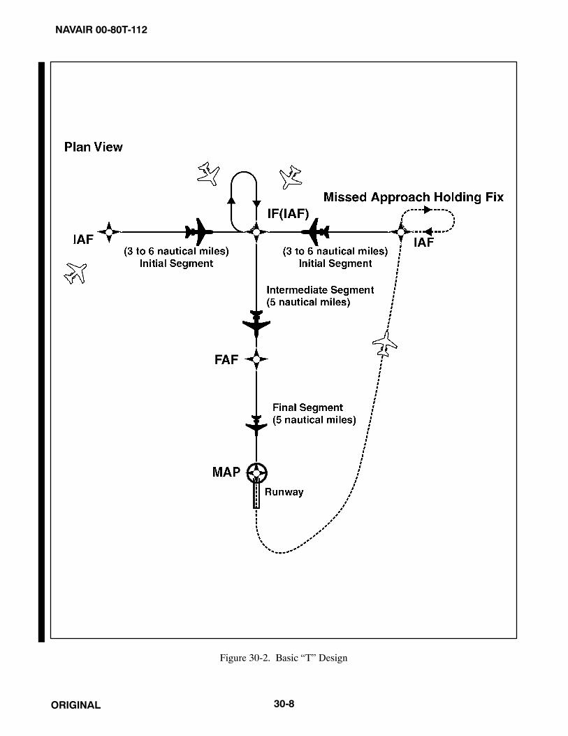
NAVAIR 00-80T-112
ORIGINAL 30-8
Figure 30-2. Basic “T” Design

NAVAIR 00-80T-112
ORIGINAL30-9
Figure 30-3. Modified Basic “T”
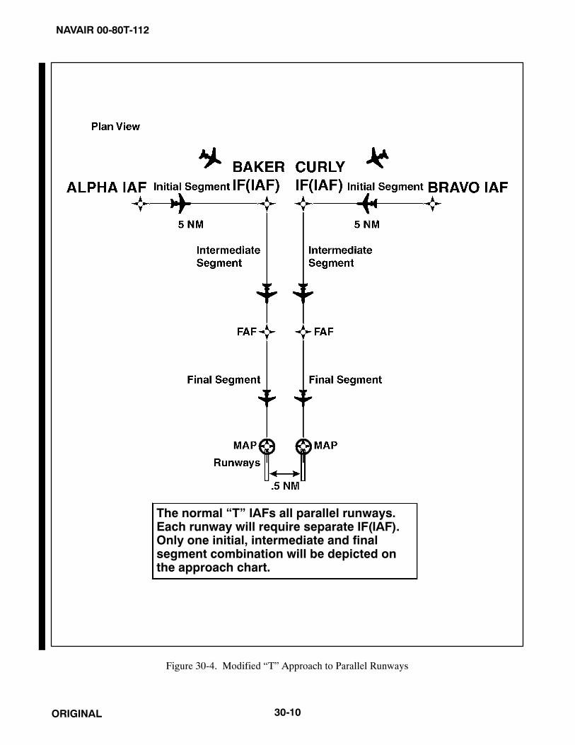
NAVAIR 00-80T-112
ORIGINAL 30-10
The normal “T” IAFs all parallel runways.Each runway will require separate IF(IAF).Only one initial, intermediate and finalsegment combination will be depicted onthe approach chart.
Figure 30-4. Modified “T” Approach to Parallel Runways

NAVAIR 00-80T-112
ORIGINAL30-11
Figure 30-5. “T” Approach with Common IAFs to Parallel Runways
Figure 30-6. “T” Approach with Common IAFs to Parallel Runways

NAVAIR 00-80T-112
ORIGINAL 30-12
5. The standard TAA consists of three areas defined by the extension of the IAF legs and the intermediate segmentcourse. These areas are called the straight-in, left-base, and right-base areas (Figure 30-7). TAA area lateralboundaries are identified by magnetic courses to the IF (IAF). The straight-in area can be further divided intopie-shaped sectors with the boundaries identified by magnetic courses to the IF (IAF) and may containstepdown sections defined by arcs based on RNAV distances (DME or Along Track Distance [ATD]) from theIF (IAF). The right/left-base areas can only be subdivided using arcs based on RNAV distances from the IAFfor those areas. Minimum Mean Sea Level (MSL) altitudes are charted within each of these definedareas/subdivisions that provide at least 1,000 feet of obstacle clearance or more, as necessary, in mountainousareas.
a. Prior to arriving at the TAA boundary, the pilot can determine which area of the TAA the aircraft will enterby selecting the IF (IAF) to determine the magnetic bearing to the IF (IAF). That bearing should then becompared with the published bearings that define the lateral boundaries of the TAA areas. This is criticalwhen approaching the TAA near the extended boundary between the left- and right-base areas, especiallywhere these areas contain different minimum altitude requirements.
b. Pilots entering the TAA and cleared by air traffic control are expected to proceed directly to the IAFassociated with that area of the TAA at the altitude depicted, unless otherwise cleared by air traffic control.Pilots entering the TAA with two-way radio communications failure (14 CFR Section 91.185, IFROperations: Two-Way Radio Communications Failure), must maintain the highest altitude prescribed bySection 91.185(c)(2) until arriving at the appropriate IAF.
c. Depiction of the TAA on U.S. Government charts will be through the use of icons located in the plan viewoutside the depiction of the actual approach procedure (Figure 30-8). Use of icons is necessary to avoidobscuring any portion of the “T” procedure (altitudes, courses, minimum altitudes, etc.). The icon for eachTAA area will be located and oriented on the plan view with respect to the direction of arrival to the approachprocedure and will show all TAA minimum altitudes and sector/radius subdivisions for that area. The IAFfor each area of the TAA is included on the icon where it appears on the approach to help the pilot orientthe icon to the approach procedure. The IAF name and the distance of the TAA area boundary from the IAFare included on the outside arc of the TAA area icon. Examples here are shown with the TAA around theapproach to aid pilots in visualizing how the TAA corresponds to the approach and should not be confusedwith the actual approach chart depiction.
d. Each waypoint on the “T,” except the missed approach waypoint, is assigned a pronounceable five-charactername used in air traffic control communications, that is found in the RNAV databases for the procedure.The missed approach waypoint is assigned a pronounceable name when it is not located at the runwaythreshold.
6. Once cleared to fly the TAA, pilots are expected to obey minimum altitudes depicted within the TAA icons,unless instructed otherwise by air traffic control. In Figure 30-9, pilots within the left-base area are expectedto maintain a minimum altitude of 10,000 feet once within 30 nm and a minimum altitude of 9,600 feet oncewithin 30 nm in the right-base area. Pilots approaching from the northeast are expected to maintain a minimumaltitude of 11,400 feet once within 30 nm, and when within 12 nm of the IF (IAF), descend to a minimumaltitude of 9,100 feet MSL until reaching the IF (IAF).

NAVAIR 00-80T-112
ORIGINAL30-13
IAF for Left Base area
Figure 30-7. TAA Areas

NAVAIR 00-80T-112
ORIGINAL 30-14
Figure 30-8. Sectored TAA Areas

NAVAIR 00-80T-112
ORIGINAL30-15
Figure 30-9. RNAV Approach Chart

NAVAIR 00-80T-112
ORIGINAL 30-16
7. Just as the underlying “T” approach procedure may be modified in shape, the TAA may contain modificationsto the defined area shapes and sizes. Some areas may even be eliminated, with other areas expanded as needed.Figure 30-10 is an example of a design limitation where a course reversal is necessary when approaching theIF (IAF) from certain directions due to the amount of turn required at the IF (IAF). Design criteria require acourse reversal whenever this turn exceeds 120 degrees. In this generalized example, pilots approaching ona bearing to the IF (IAF) from 300° clockwise through 060° are expected to execute a course reversal. The termNoPT will be annotated on the boundary of the TAA icon for the other portion of the TAA.
8. Figure 30-11 depicts another TAA modification that pilots may encounter. In this generalized example, theright-base area has been eliminated. Pilots operating within the TAA between 360° clockwise to 060° bearingto the IF (IAF) are expected to execute the course reversal in order to properly align the aircraft for entry ontothe intermediate segment. Aircraft operating in all other areas from 060° clockwise to 360° bearing to the IF(IAF) need not perform the course reversal, and the term “NoPT” will be annotated on the TAA boundary ofthe icon in these areas.
9. When an airway does not cross the lateral TAA boundaries, a feeder route will be established to provide atransition from the en route structure to the appropriate IAF. Each feeder route will terminate at the TAAboundary and will be aligned along a path pointing to the associated IAF. Pilots should descend to the TAAaltitude after crossing the TAA boundary and cleared by air traffic control (Figure 30-12).
30.5.3 Minimum Vectoring Altitude (MVA)
The Minimum Vectoring Altitude (MVA) is established for use by ATC when radar ATC is exercised. MVA chartsare prepared by air traffic facilities at locations where there are numerous different minimum IFR altitudes. EachMVA chart has sectors large enough to accommodate vectoring of aircraft within the sector at the MVA. Each sectorboundary within 40 miles of the radar is at least 3 miles from the obstruction determining the MVA. Each sectorboundary 40 miles or more from the radar is at least 5 miles from the obstruction determining the MVA. To avoid alarge sector with an excessively high MVA due to an isolated prominent obstruction, the obstruction may be enclosedin a buffer area. This is done to facilitate vectoring around the obstruction (Figure 30-13).
1. The minimum vectoring altitude in each sector provides 1,000 feet above the highest obstacle innonmountainous areas and 2,000 feet above the highest obstacle in designated mountainous areas. Wherelower MVA are required in designated mountainous areas to achieve compatibility with terminal routes or topermit vectoring to an IAP, 1,000 feet of obstacle clearance may be authorized with the use of AirportSurveillance Radar (ASR). The minimum vectoring altitude will provide at least 300 feet above the floor ofcontrolled airspace.
NoteThe Off-Route Obstruction Clearance Altitude (OROCA) is an off-routealtitude that provides obstruction clearance with a 1,000-foot buffer innonmountainous terrain areas and a 2,000-foot buffer in designatedmountainous areas within the U.S. This altitude may not provide signalcoverage from ground-based navigational aids, air traffic control radar, orcommunications coverage.
2. Because of differences in the areas considered for MVA, those applied to other minimum altitudes, and theability to isolate specific obstacles, some MVA may be lower than the nonradar MEAs, Minimum ObstructionClearance Altitudes (MOCAs)or other minimum altitudes depicted on charts for a given location. While beingradar vectored, IFR altitude assignments by ATC will be at or above MVA.

NAVAIR 00-80T-112
ORIGINAL30-17
Figure 30-10. TAA with Left- and Right-Base Areas Eliminated

NAVAIR 00-80T-112
ORIGINAL 30-18
Figure 30-11. TAA with Right Base Eliminated
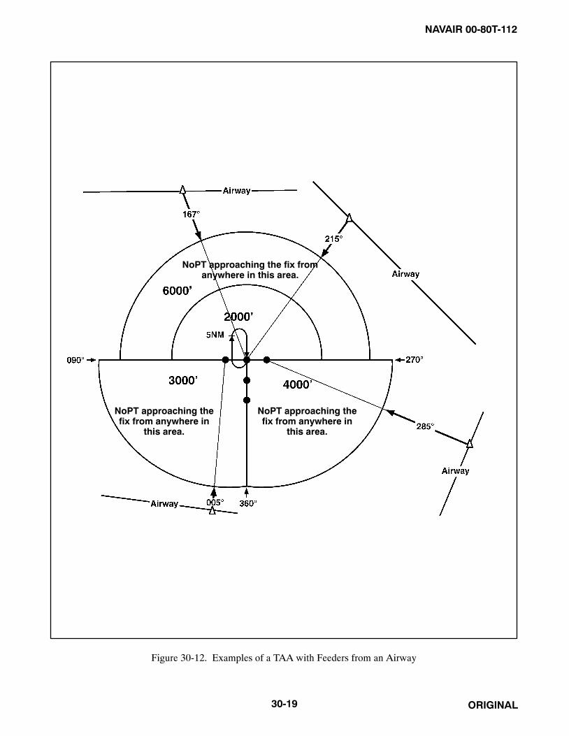
NAVAIR 00-80T-112
ORIGINAL30-19
NoPT approaching thefix from anywhere in
this area.
NoPT approaching thefix from anywhere in
this area.
NoPT approaching the fix fromanywhere in this area.
Figure 30-12. Examples of a TAA with Feeders from an Airway

NAVAIR 00-80T-112
ORIGINAL 30-20
Figure 30-13. Minimum Vectoring Altitude Charts

NAVAIR 00-80T-112
ORIGINAL30-21
30.5.4 Visual Descent Point (VDP)
VDPs are being incorporated in selected nonprecision approach procedures. The VDP is a defined point on the finalapproach course of a nonprecision straight-in approach procedure from which normal descent from the MDA to therunway touchdown point may be commenced, provided visual reference required by 14 CFR Section 91.175(c)(3)is established. The VDP will normally be identified by DME on VOR and LOC procedures and by a long trackdistance to the next waypoint for RNAV procedures. The VDP is identified on the profile view of the approach chartby the symbol V.
1. VDPs are intended to provide additional guidance where they are implemented. No special technique isrequired to fly a procedure with a VDP. The pilot should not descend below the MDA prior to reaching the VDPand acquiring the necessary visual reference.
2. Pilots not equipped to receive the VDP should fly the approach procedure as though no VDP had beenprovided.
30.5.5 Visual Portion of the Final Segment
Instrument procedures designers perform a visual area obstruction evaluation off the approach end of each runwayauthorized for instrument landing, straight-in, or circling. Restrictions to instrument operations are imposed ifpenetrations of the obstruction clearance surfaces exist. These restrictions vary based on the severity of thepenetrations and may include increasing required visibility, denying VDPs, and prohibiting night instrumentoperations to the runway.
30.5.6 Vertical Descent Angle (VDA) on Nonprecision Approaches
Descent angles are currently being published on selected nonprecision approaches. The FAA intends to eventuallypublish Vertical Descent Angles (VDAs) on all nonprecision approaches. Published along with the VDA is theThreshold Crossing Height (TCH) (i.e., the height of the descent angle above the landing threshold). The descentangle describes a computed path from the FAF and altitude to the runway threshold at the published TCH. Theoptimum descent angle is 3.00 degrees; whenever possible, the approach will be designed to accommodate this angle.
1. The VDA provides the pilot with information not previously available on nonprecision approaches. It providesthe means for the pilot to establish a stabilized approach descent from the FAF or stepdown fix to the TCH.Stabilized descent along this path is a key factor in the reduction of Controlled Flight Into Terrain (CFIT)incidents. Pilots can use the published angle and estimated/actual groundspeed to find a target rate of descentfrom a rate of descent table published with the instrument approach procedures.
2. Normally, the VDA will first appear on the nonprecision approach chart as the procedure is amended throughthe normal process; however, in some cases, pilots can expect to see this data provided via a NOTAM(D).
3. Pilots should be aware that the published angle is for information only — it is strictly advisory in nature. Thereis no implicit additional obstacle protection below the MDA. Pilots must still respect the published MDAunless the visual cues stated in 14 CFR Section 91.175 are present. In rare cases, the published proceduredescent angle will not coincide with the Visual Glideslope Indicator (VGSI), Visual Approach Slope Indicator(VASI) or Precision Approach Path Indicator (PAPI). In these cases, the procedure will be annotated: “VGSIand descent angle not coincident.”
30.5.7 Pilot Operational Considerations When Flying Nonprecision Approaches
The MAP on a nonprecision approach is not designed with any consideration to where the aircraft must begin descentto execute a safe landing. It is developed based on terrain, obstructions, NAVAID location, and possibly air trafficconsiderations. Because the MAP may be located anywhere from well prior to the runway threshold to past the

NAVAIR 00-80T-112
ORIGINAL 30-22
opposite end of the runway, the descent from the MDA to the runway threshold cannot be determined based on theMAP location. Descent from MDA at the MAP when the MAP is located close to the threshold would require anexcessively steep descent gradient to land in the normal touchdown zone. Any turn from the final approach courseto the runway heading may also be a factor in when to begin the descent.
1. Pilots are cautioned that descent to a straight-in landing from the MDA at the MAP may be inadvisable orimpossible, on a nonprecision approach, even if current weather conditions meet the published ceiling andvisibility. Aircraft speed, height above the runway, descent rate, amount of turn, and runway length are someof the factors that must be considered by the pilot to determine if a landing can be accomplished.
2. Visual Descent Points (VDPs) provide pilots with a reference for the optimal location to begin descent fromthe MDA, based on the designed VDA for the approach procedure, assuming required visual references areavailable. Approaches without VDPs have not been assessed for terrain clearance below the MDA and maynot provide a clear vertical path to the runway at the normally expected descent angle; therefore, pilots mustbe especially vigilant when descending below the MDA at locations without VDPs. This does not necessarilyprevent flying the normal angle; it only means that obstacle clearance in the visual segment could be less andgreater care should be exercised in looking for obstacles in the visual segment. Use of VGSI systems can aidthe pilot in determining if the aircraft is in a position to make the descent from the MDA; however, when thevisibility is close to minimums, the VGSI may not be visible at the start descent point for a normal glidepathdue to its location down the runway.
3. Accordingly, pilots are advised to carefully review approach procedures, prior to initiating the approach, toidentify the optimum position(s), and any unacceptable positions, from which a descent to landing can beinitiated (in accordance with 14 CFR Section 91.175(c)).
30.5.8 Area Navigation (RNAV) Instrument Approach Charts
Reliance on RNAV systems for instrument approach operations is becoming more commonplace as new systems suchas GPS, Wide Area Augmentation System (WAAS), and Local Area Augmentation System (LAAS) are developedand deployed. In order to foster and support full integration of RNAV into the National Airspace System (NAS), theFAA has developed a new charting format for RNAV IAPs (Figure 30-8). This format avoids unnecessary duplicationand proliferation of instrument approach charts. The approach minimums for unaugmented GPS (the present GPSapproaches) and augmented GPS (WAAS and LAAS when they become operational) will be published on the sameapproach chart. The approach chart will be titled RNAV (GPS) RWY XX. The first RNAV approach charts mayappear as stand-alone “GPS” procedures, prior to WAAS becoming operational. Accordingly, the minimums lineassociated with WAAS may be marked NA until the navigation system is operational. The chart may contain as manyas four lines of approach minimums: Global Navigation Satellite System (GNSS) Landing System (GLS), LPV,Lateral Navigation/Vertical Navigation (LNAV/VNAV), LNAV, and CIRCLING. GLS includes WAAS and LAAS.LNAV/VNAV is a new type of instrument approach with lateral and vertical navigation. During a transition periodwhen GPS procedures are undergoing revision, the new title RNAV (GPS) approach charts and formats will bepublished. ATC clearance for the RNAV procedure will authorize a properly certified pilot to utilize any landingminimums for which the aircraft is certified. The RNAV (GPS) chart will include formatted information required forquick pilot or flightcrew reference located at the top of the chart. This portion of the chart, developed based on a studyby the Department of Transportation, Volpe National Transportation Systems Center, is commonly referred to as thepilot briefing, or EZ Brief.
1. New minimums lines will be:
a. GLS. “GLS” is the acronym for GNSS Landing System; GNSS is the acronym for Global NavigationSatellite System. The minimums line labeled GLS will accommodate aircraft equipped with precisionapproach capable WAAS receivers operating to their fullest capability. WAAS, as its name implies,augments the basic GPS satellite constellation with additional ground stations and enhancedposition/integrity information transmitted from geostationary satellites. This capability of augmentation

NAVAIR 00-80T-112
ORIGINAL30-23
enhances both the accuracy and integrity of basic GPS and may support precision (GLS) approachminimums as low as 200-foot Height Above Touchdown (HAT) and 1/2 statute mile (SM) visibility.Publication of the lowest GLS minimums requires that certain interrelated conditions of satellite availabilityand runway landing environment are met. The suitability of the landing environment to support the lowestlanding minimums is determined by the degree of airport compliance with AC 150/5300-13, AirportDesign. Precision runway and airport compliance factors include runway marking and lighting, obstacleclearance surfaces, runway length, approach lighting, taxiway layout, etc. Pilots will be informed that allthe requirements of the precision runway landing environment are satisfied by the notation GLS PA (GNSSLanding System Precision Approach) on the first line of minimums in U.S. Government TerminalProcedure Publication charts. Pilots will be informed that not all of the precision runway requirements aremet by the notation GLS without the letters “PA” on the first line of minimums. In this latter case, theairborne WAAS receiver may be operating in the most capable mode, but because the landing environmentdoes not support the low-visibility operations, minimums no lower than 300-foot HAT and 3/4 SM visibilitywill be published. Since computed glidepath guidance is provided to the pilot, procedure minimum altitudewill be published as a Decision Altitude (DA).
b. LNAV/VNAV identifies minimums developed to accommodate an RNAV IAP with vertical guidance, butwith integrity limits larger than a precision approach. LNAV stands for Lateral Navigation; VNAV standsfor Vertical Navigation. Aircraft using LNAV/VNAV minimums will descend to landing via an internallygenerated descent path based on satellite or other approach approved VNAV systems. WAAS equipmentmay revert to this mode of operation when the signal does not support the highest level of accuracy andintegrity. Since electronic vertical guidance is provided, the minimums will be published as a DA. Othernavigation systems may be specifically authorized to use this line of minimums; see Section A,Terms/Landing Minimums Data, of the U.S. Terminal Procedures books for a more detailed explanation.
c. LNAV. This minimum is for lateral navigation only, and the approach minimum altitude will be publishedas an MDA because vertical guidance is not provided. LNAV provides the same level of service as thepresent GPS stand-alone approaches. LNAV minimums support the following navigation systems: WAAS(when the navigation solution will not support vertical navigation) and GPS navigation systems which arepresently authorized to conduct GPS approaches. The LNAV line on the RNAV chart will allow the presentapproach certified receivers to fly the new approaches. Existing GPS approaches will be converted to thisformat. (The receiver must be approved for approach operations in accordance with: AC 20-138,Airworthiness Approval of Global Positioning System [GPS] Navigation Equipment for Use as a VisualFlight Rules [VFR] and IFR Supplemental Navigation System, for stand-alone TSO-C128 Class A(1)systems; or AC 20-130A, Airworthiness Approval of Navigation or Flight Management SystemsIntegrating Multiple Navigation Sensors, for GPS as part of a multisensor system, qualify for thisminimum.)
2. Other systems may be authorized to utilize these approaches. See the description in Section A of the U.S.Terminal Procedures books for details. Through a special authorization, aircraft equipped with other IFRapproach approved RNAV systems may fly to the LNAV/VNAV and/or LNAV minimums described above.These systems may include aircraft equipped with an FMS that can file /E or /F. Operational approval mustalso be obtained for Barometric Vertical Navigation (BARO-VNAV) systems to operate to the LNAV/VNAVminimums. BARO-VNAV may not be authorized on some approaches due to other factors. Pilots are directedto their local Flight Standards District Office (FSDO) for additional information.
Note
RNAV and BARO-VNAV systems must have a manufacturer-suppliedelectronic database that shall include the waypoints, altitudes, and verticaldata for the procedure to be flown. The system shall also be able to extractthe procedure in its entirety, not just as a series of waypoints.

NAVAIR 00-80T-112
ORIGINAL 30-24
3. Required Navigation Performance (RNP).
a. With the widespread deployment of RNAV systems, the advent of GPS, and the imminent implementationof WAAS, greater flexibility in route, procedure, and airspace design is now possible, with an associatedincrease in navigation accuracy and flight safety. To capitalize on the potential of RNAV systems, the FAAand the International Civil Aviation Organization (ICAO) are effecting a shift toward a new standard ofnavigation and airspace management called RNP.
b. Navigation systems have typically been described as being sensor specific, such as VOR, NDB, and ILSsystems. When RNP is specified, it does not matter what the underlying navigation system or combinationof systems is used, provided the aircraft can achieve the required navigation performance. Typically, varioussensor inputs are processed by the RNAV system to arrive at a position estimate having a high statisticaldegree of accuracy and confidence. RNP is intended to provide a single performance standard that can beused and applied to aircraft and aircraft equipment manufacturers, airspace, planners, aircraft certificationand operations, pilots and controllers, and international aviation authorities. RNP can be related to obstacleclearance or aircraft separation requirements to ensure a consistent level of application.
c. An RNP level or type is applicable to a selected airspace, route, or procedure. The applicable RNP isexpressed as a value that represents a distance in nautical miles from the intended position to the actualposition of an aircraft. It is within this distance that an aircraft would normally be expected to operate. Forgeneral RNAV approach procedures, RNP 0.3 is required.
d. Pilots are advised to refer to the “TERPS/LANDING MINIMUMS DATA” (Section A) of the U.S.Government Terminal Procedures books for aircraft approach eligibility requirements by specific RNPlevel requirements. Aircraft meeting RNP criteria will have an appropriate entry, including specialconditions and limitations, if any, in the Aircraft Flight Manual (AFM) or its supplement. This will onlyoccur when it has been determined that the aircraft complies with the appropriate provisions of certification.
e. Some aircraft have RNP approval in their AFM without a GPS sensor. The lowest level of sensors that theFAA will support for RNP service is DME/DME; however, necessary DME NAVAID ground infrastructuremay or may not be available at the airport of intended operations. For those locations having an RNAV chartpublished with LNAV/VNAV minimums, a procedure note may be provided (e.g., DME/DME RNP 0.3NA; this means that RNP aircraft dependent on DME/DME to achieve RNP 0.3 are not authorized toconduct this approach). Where FAA flight inspection successfully determines the availability and geometryof DME facilities will support RNP 0.3 and the DME signal meets inspection tolerances, a note such as“DME/DME RNP 0.3 Authorized” will appear on the chart. Where DME facility availability is a factor,the note may read “DME/DME RNP 0.3 Authorized; ABC and XYZ Required,” meaning that ABC andXYZ facilities have been determined by flight inspection to be required in the navigation solution to ensureRNP 0.3.
4. Chart terminology will change slightly to support the new procedure types.
a. Decision Altitude (DA) replaces the familiar term Decision Height (DH). DA conforms to the internationalconvention where altitudes relate to MSL and heights relate to Above Ground Level (AGL). DA willeventually be published for other types of instrument approach procedures with vertical guidance as well.DA indicates to the pilot that the published descent profile is flown to the DA (MSL), where a missedapproach will be initiated if visual references for landing are not established. Obstacle clearance is providedto allow a momentary descent below DA while transitioning from the final approach to the missed approach.The aircraft is expected to follow the missed instructions while continuing along the published finalapproach course to at least the published runway threshold waypoint or MAP (if not at the threshold) beforeexecuting any turns.
b. Minimum Descent Altitude (MDA) has been in use for many years and will continue to be used for theLNAV only and circling procedures.
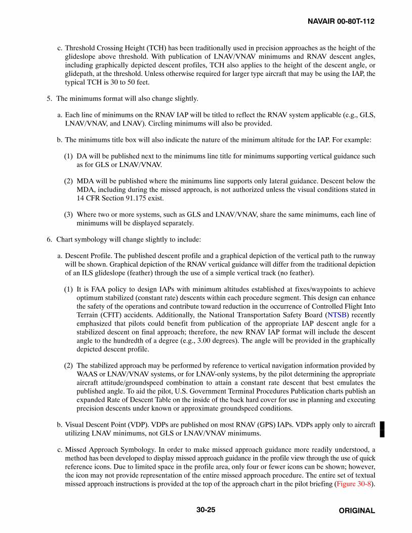
NAVAIR 00-80T-112
ORIGINAL30-25
c. Threshold Crossing Height (TCH) has been traditionally used in precision approaches as the height of theglideslope above threshold. With publication of LNAV/VNAV minimums and RNAV descent angles,including graphically depicted descent profiles, TCH also applies to the height of the descent angle, orglidepath, at the threshold. Unless otherwise required for larger type aircraft that may be using the IAP, thetypical TCH is 30 to 50 feet.
5. The minimums format will also change slightly.
a. Each line of minimums on the RNAV IAP will be titled to reflect the RNAV system applicable (e.g., GLS,LNAV/VNAV, and LNAV). Circling minimums will also be provided.
b. The minimums title box will also indicate the nature of the minimum altitude for the IAP. For example:
(1) DA will be published next to the minimums line title for minimums supporting vertical guidance suchas for GLS or LNAV/VNAV.
(2) MDA will be published where the minimums line supports only lateral guidance. Descent below theMDA, including during the missed approach, is not authorized unless the visual conditions stated in14 CFR Section 91.175 exist.
(3) Where two or more systems, such as GLS and LNAV/VNAV, share the same minimums, each line ofminimums will be displayed separately.
6. Chart symbology will change slightly to include:
a. Descent Profile. The published descent profile and a graphical depiction of the vertical path to the runwaywill be shown. Graphical depiction of the RNAV vertical guidance will differ from the traditional depictionof an ILS glideslope (feather) through the use of a simple vertical track (no feather).
(1) It is FAA policy to design IAPs with minimum altitudes established at fixes/waypoints to achieveoptimum stabilized (constant rate) descents within each procedure segment. This design can enhancethe safety of the operations and contribute toward reduction in the occurrence of Controlled Flight IntoTerrain (CFIT) accidents. Additionally, the National Transportation Safety Board (NTSB) recentlyemphasized that pilots could benefit from publication of the appropriate IAP descent angle for astabilized descent on final approach; therefore, the new RNAV IAP format will include the descentangle to the hundredth of a degree (e.g., 3.00 degrees). The angle will be provided in the graphicallydepicted descent profile.
(2) The stabilized approach may be performed by reference to vertical navigation information provided byWAAS or LNAV/VNAV systems, or for LNAV-only systems, by the pilot determining the appropriateaircraft attitude/groundspeed combination to attain a constant rate descent that best emulates thepublished angle. To aid the pilot, U.S. Government Terminal Procedures Publication charts publish anexpanded Rate of Descent Table on the inside of the back hard cover for use in planning and executingprecision descents under known or approximate groundspeed conditions.
b. Visual Descent Point (VDP). VDPs are published on most RNAV (GPS) IAPs. VDPs apply only to aircraftutilizing LNAV minimums, not GLS or LNAV/VNAV minimums.
c. Missed Approach Symbology. In order to make missed approach guidance more readily understood, amethod has been developed to display missed approach guidance in the profile view through the use of quickreference icons. Due to limited space in the profile area, only four or fewer icons can be shown; however,the icon may not provide representation of the entire missed approach procedure. The entire set of textualmissed approach instructions is provided at the top of the approach chart in the pilot briefing (Figure 30-8).
NAVAIR 00-80T-112
ORIGINAL 30-26
d. Waypoints. All RNAV or GPS stand-alone IAPs are flown using data pertaining to the particular IAPobtained from an onboard database, including the sequence of all WPs used for the approach and missedapproach. Included in the database, in most receivers, is coding that informs the navigation system of whichWaypoints (WPs) are fly-over or fly-by. The navigation system may provide guidance appropriately,including leading the turn prior to a Fly-By Waypoint (FBWP), or causing overflight of a Fly-OverWaypoint (FOWP). Where the navigation system does not provide such guidance, the pilot must accomplishthe turn lead or waypoint overflight manually. Chart symbology for the FBWP provides pilot awareness ofexpected actions. Refer to the legend of the U.S. Terminal Procedures books.
e. TAAs are described in paragraph 30.5.2. When published, the new RNAV chart will depict the TAA areasthrough the use of icons representing each TAA area associated with the RNAV procedure. These icons willbe depicted in the plan view of the approach chart, generally arranged on the chart in accordance with theirposition relative to the aircraft arrival from the en route structure. The WP, to which navigation isappropriate and expected within each specific TAA area, will be named and depicted on the associated TAAicon. Each depicted named WP is the IAF for arrivals from within that area. TAAs may not be depicted onall RNAV procedures because of the inability for ATC to accommodate the TAA due to airspace congestion.
f. Cold Temperature Limitations. A minimum temperature limitation will be published for each procedure forwhich BARO-VNAV operations are authorized. This temperature represents the airport temperature belowwhich use of the BARO-VNAV will not be authorized to the LNAV/VNAV minimums. An examplelimitation will read: “BARO-VNAV NA below –20 °C (–4 °F).” This information will be found in the upperleft-hand box of the pilot briefing.
g. WAAS Channel Number/Approach ID. The WAAS Channel Number is an equipment optional capabilitythat allows the use of a five-digit number to select a specific instrument approach procedure. The ApproachID is a unique four-letter combination for verifying selection of the correct procedure. The WAAS ChannelNumber and Approach ID will be displayed prominently in the approach procedure pilot briefing. TheWAAS Channel Number and Approach ID provide one method available to the pilot for selecting andverifying the approach procedure for the runway of intended landing from the onboard databases. Someequipment may utilize a menu selection method.
(1) The Menu Method. In general, although the steps may vary among equipment types, the pilot firstselects the airport of intended landing using the airborne equipment control panel. From a menu thatis presented for this airport, the pilot then selects the approach runway. Selecting, from the menu, theApproach ID that matches the Approach ID printed on the approach chart then makes selection of thespecific approach procedure. Finally, the pilot activates the procedure by selecting the IAF with whichto begin the approach.
(2) Five-Digit Channel Number Method. The pilot enters the unique five-digit number provided for theapproach chart, and the receiver recalls a specific approach procedure from the aircraft database. A listof information including the Approach ID and available IAFs is displayed. The pilot confirms thecorrect procedure is selected by comparing the Approach ID listed with that printed on the approachchart. Finally, the pilot activates the procedure by selecting the appropriate IAF with which to begin theapproach.
30.6 APPROACH CLEARANCE
An aircraft that has been cleared to a holding fix and subsequently “cleared . . . approach” has not received newrouting. Even though clearance for the approach may have been issued prior to the aircraft reaching the holding fix,ATC would expect the pilot to proceed via the holding fix (the last assigned route) and the feeder route associatedwith that fix (if a feeder route is published on the approach chart) to the IAF to commence the approach.
NAVAIR 00-80T-112
ORIGINAL30-27
NoteWhen cleared for the approach, the published off airway (feeder) routes thatlead from the en route structure to the IAF are part of the approachclearance.
If a feeder route to an IAF begins at a fix located along the route of flight prior to reaching the holding fix, andclearance for an approach is issued, a pilot should commence the approach via the published feeder route (i.e., theaircraft would not be expected to overfly the feeder route and return to it). The pilot is expected to commence theapproach in a similar manner at the IAF if the IAF for the procedure is located along the route of flight to the holdingfix.
If a route of flight directly to the initial approach fix is desired, it should be so stated by the controller with phraseologyto include the words “direct,” “proceed direct,” or a similar phrase that the pilot can interpret without question. Whenuncertain of the clearance, immediately query ATC as to what route of flight is desired.
The name of an instrument approach, as published, is used to identify the approach, even though a component of theapproach aid, such as the glideslope on an instrument landing system, is inoperative or unreliable. The controller willuse the name of the approach as published, but must advise the aircraft at the time an approach clearance is issuedthat the inoperative or unreliable approach aid component is unusable.
30.7 INSTRUMENT APPROACH PROCEDURES
Minimums are specified for various aircraft approach categories based upon a value 1.3 times the stalling speed ofthe aircraft in the landing configuration at maximum certified gross landing weight. In 14 CFR Section 97.3(b)categories are listed as follows:
1. Category A: Speed less than 91 knots.
2. Category B: Speed 91 knots or more but less than 121 knots.
3. Category C: Speed 121 knots or more but less than 141 knots.
4. Category D: Speed 141 knots or more but less than 166 knots.
5. Category E: Speed 166 knots or more.
Aircraft approach categories are also discussed in the U.S. Terminal Procedures (commonly called approach plates),which states, among other things, that “An aircraft shall fit in only one category. If it is necessary to maneuver atspeeds in excess of the upper limit of a speed range for a category, the minimums for the next higher category shouldbe used.” If it is necessary, while circling to land, to maneuver at speeds in excess of the upper limit of the speed rangefor each category, due to the possibility of extending the circling maneuver beyond the area for which obstructionclearance is provided, the circling minimum for the next higher approach category should be used. For example, anaircraft that falls in Category C, but is circling to land at a speed of 141 knots or higher, should use the approachCategory D minimum when circling to land.
When operating on an unpublished route or while being radar vectored, the pilot, when an approach clearance isreceived, shall, in addition to complying with the minimum altitudes for IFR operations (14 CFR Section 91.177),maintain the last assigned altitude unless a different altitude is assigned by ATC, or until the aircraft is establishedon a segment of a published route or IAP. After the aircraft is so established, published altitudes apply to descentwithin each succeeding route or approach segment unless a different altitude is assigned by ATC. Notwithstandingthis pilot responsibility for aircraft operating on unpublished routes or while being radar vectored, ATC will, exceptwhen conducting a radar approach, issue an IFR approach clearance only after the aircraft is established on a segmentof a published route or IAP, or assign an altitude to maintain until the aircraft is established on a segment of a publishedroute or instrument approach procedure. For this purpose, the procedure turn of a published IAP shall not beconsidered a segment of that IAP until the aircraft reaches the initial fix or navigation facility upon which theprocedure turn is predicated.

NAVAIR 00-80T-112
ORIGINAL 30-28
NoteThe altitude assigned will ensure IFR obstruction clearance from the pointat which the approach clearance is issued until established on a segment ofa published route or IAP. If uncertain of the meaning of the clearance,immediately request clarification from ATC.
Several IAPs, using various navigation and approach aids, may be authorized for an airport. ATC may advise that aparticular approach procedure is being used, primarily to expedite traffic. If issued a clearance that specifies aparticular approach procedure, notify ATC immediately if a different one is desired. In this event it may be necessaryfor ATC to withhold clearance for the different approach until such time as traffic conditions permit; however, a pilotinvolved in an emergency situation will be given priority. If the pilot is not familiar with the specific approachprocedure, ATC should be advised and they will provide detailed information on the execution of the procedure.
At times, ATC may not specify a particular approach procedure in the clearance, but will state “CLEAREDAPPROACH.” Such clearance indicates that the pilot may execute any one of the authorized IAPs for that airport.This clearance does not constitute approval for the pilot to execute a contact approach or a visual approach.
Except when being radar vectored to the final approach course, when cleared for a specifically prescribed IAP (i.e.,“cleared ILS runway one niner approach”) or when “cleared approach” (i.e., execution of any procedure prescribedfor the airport), pilots shall execute the entire procedure commencing at an IAF or an associated feeder route asdescribed on the IAP chart unless an appropriate new or revised ATC clearance is received or the IFR flight plan iscanceled.
Pilots planning flights to locations served by special IAPs should obtain advance approval from the owner of theprocedure. Approval by the owner is necessary because special procedures are for the exclusive use of the singleinterest unless otherwise authorized by the owner. Additionally, some special approach procedures require certaincrew qualifications training or other special considerations in order to execute the approach. Also, some of theseapproach procedures are based on privately owned navigational aids. Owners of aids that are not for public use mayelect to turn off the aid for whatever reason they may have (e.g., maintenance, conservation, etc.). Air trafficcontrollers are not required to question pilots to determine if they have permission to use the procedure. Controllerspresume a pilot has obtained approval and is aware of any details of the procedure if an IFR flight plan was filed tothat airport.
When executing an instrument approach and in radio contact with an FAA facility, unless in radar contact, reportpassing the final approach fix inbound (nonprecision approach) or the outer marker or fix used in lieu of the outermarker inbound (precision approach).
Pilots should not rely on radar to identify a fix unless the fix is indicated as RADAR on the IAP. Pilots may requestradar identification of an OM, but the controller may not be able to provide the service due either to workload or nothaving the fix on the video map.
If a missed approach is required, advise ATC and include the reason (unless initiated by ATC). Comply with themissed approach instructions for the instrument approach procedure being executed unless otherwise directed byATC.
30.8 PROCEDURE TURN
A procedure turn is the maneuver prescribed when it is necessary to perform a course reversal to establish the aircraftinbound on an intermediate or final approach course. The procedure turn or hold in lieu of procedure turn is a requiredmaneuver. The procedure turn is not required when the symbol NoPT is shown, when radar vectoring to the finalapproach course is provided, when conducting a timed approach, or when the procedure turn is not authorized. Thehold in lieu of procedure turn is not required when radar vectoring to the final approach course is provided or whenNoPT is shown. The altitude prescribed for the procedure turn is a minimum altitude until the aircraft is establishedon the inbound course. The maneuver must be completed within the distance specified in the profile view.

NAVAIR 00-80T-112
ORIGINAL30-29
1. On U.S. Government charts, a barbed arrow indicates the direction or side of the outbound course on whichthe procedure turn is made. Headings are provided for course reversal using the 45-degree type procedure turn;however, the point at which the turn may be commenced and the type and rate of turn is left to the discretionof the pilot. Some of the options are the 45-degree procedure turn, the racetrack pattern, the teardrop procedureturn, or the 80 degree ↔ 260 degree course reversal. Some procedure turns are specified by procedural track.These turns must be flown exactly as depicted.
2. When the approach procedure involves a procedure turn, a maximum speed of not greater than 200 knotsIndicated Airspeed (IAS) should be observed from first overhead the course reversal IAF through theprocedure turn maneuver to ensure containment within the obstruction clearance area. Pilots should begin theoutbound turn immediately after passing the procedure turn fix. The procedure turn maneuver must beexecuted within the distance specified in the profile view. The normal procedure turn distance is 10 miles. Thismay be reduced to a minimum of 5 miles where only Category A or helicopter aircraft are to be operated orincreased to as much as 15 miles to accommodate high-performance aircraft.
3. A teardrop procedure or penetration turn may be specified in some procedures for a required course reversal.The teardrop procedure consists of departure from an initial approach fix on an outbound course followed bya turn toward and intercepting the inbound course at or prior to the intermediate fix or point. Its purpose is topermit an aircraft to reverse direction and lose considerable altitude within reasonably limited airspace. Whereno fix is available to mark the beginning of the intermediate segment, it shall be assumed to commence at apoint 10 miles prior to the final approach fix. When the facility is located on the airport, an aircraft is consideredto be on final approach upon completion of the penetration turn; however, the final approach segment beginson the final approach course 10 miles from the facility.
4. A holding pattern in lieu of procedure turn may be specified for course reversal in some procedures. In suchcases, the holding pattern is established over an intermediate fix or a final approach fix. The holding patterndistance or time specified in the profile view must be observed. Maximum holding airspeed limitations, as setforth for all holding patterns, apply. The holding pattern maneuver is completed when the aircraft is establishedon the inbound course after executing the appropriate entry. If cleared for the approach prior to returning tothe holding fix, and the aircraft is at the prescribed altitude, additional circuits of the holding pattern are notnecessary nor expected by ATC. If pilots elect to make additional circuits to lose excessive altitude or to becomebetter established on course, it is their responsibility to so advise ATC upon receipt of their approach clearance.
5. A procedure turn is not required when an approach can be made directly from a specified intermediate fix tothe final approach fix. In such cases, the term NoPT is used with the appropriate course and altitude to denotethat the procedure turn is not required. If a procedure turn is desired, and when cleared to do so by ATC, descentbelow the procedure turn altitude should not be made until the aircraft is established on the inbound course,since some NoPT altitudes may be lower than the procedure turn altitudes.
30.8.1 Limitations on Procedure Turns
1. In the case of a radar initial approach to a final approach fix or position, or a timed approach from a holdingfix, or where the procedure specifies NoPT, no pilot may make a procedure turn unless, when final approachclearance is received, the pilot so advises ATC and a clearance is received to execute a procedure turn.
2. When a teardrop procedure turn is depicted and a course reversal is required, this type turn must be executed.
3. When a holding pattern replaces a procedure turn, the holding pattern must be followed, except when radarvectoring is provided or when NoPT is shown on the approach course. The recommended entry procedureswill ensure the aircraft remains within the holding pattern protected airspace. As in the procedure turn, thedescent from the minimum holding pattern altitude to the final approach fix altitude (when lower) may notcommence until the aircraft is established on the inbound course. Where a holding pattern is established in lieuof a procedure turn, the maximum holding pattern airspeeds apply.
4. The absence of the procedure turn barb in the plan view indicates a procedure turn is not authorized for thatprocedure.

NAVAIR 00-80T-112
ORIGINAL 30-30
30.9 TIMED APPROACHES FROM A HOLDING FIX
Timed approaches may be conducted when the following conditions are met:
1. A control tower is in operation at the airport where the approaches are conducted.
2. Direct communications are maintained between the pilot and the center or approach controller until the pilotis instructed to contact the tower.
3. If more than one missed approach procedure is available, none require a course reversal.
4. If only one missed approach procedure is available, the following conditions are met:
a. Course reversal is not required.
b. Reported ceiling and visibility are equal to or greater than the highest prescribed circling minimums for theIAP.
5. When cleared for the approach, pilots shall not execute a procedure turn. (14 CFR Section 91.175.)
Although the controller will not specifically state that timed approaches are in progress, the assigning of a time todepart the final approach fix inbound (nonprecision approach) or the outer marker or fix used in lieu of the outermarker inbound (precision approach) is indicative that timed approach procedures are being utilized, or in lieu ofholding, the controller may use radar vectors to the final approach course to establish a mileage interval betweenaircraft that will ensure the appropriate time sequence between the final approach fix/outer marker or fix used in lieuof the outer marker and the airport.
Each pilot in an approach sequence will be given advance notice as to the time they should leave the holding pointon approach to the airport. When a time to leave the holding point has been received, the pilot should adjust the flightpath to leave the fix as closely as possible to the designated time (Figure 30-14).
Example:
At 12:03 local time, in the example shown, a pilot holding receives instructions to leave the fix inbound at 12:07.These instructions are received just as the pilot has completed turn at the outbound end of the holding pattern and isproceeding inbound toward the fix. Arriving back over the fix, the pilot notes the time is 12:04 and there are 3 minutesto lose in order to leave the fix at the assigned time. Since the time remaining is more than 2 minutes, the pilot plansto fly a racetrack pattern rather than a 360-degree turn, which would use up 2 minutes. The turns at the ends of theracetrack pattern will consume approximately 2 minutes. Three minutes to go, minus 2 minutes required for the turns,leaves 1 minute for level flight. Since two portions of level flight will be required to get back to the fix inbound, thepilot halves the 1 minute remaining and plans to fly level for 30 seconds outbound before starting the turn back tothe fix on final approach. If the winds were negligible at flight altitude, this procedure would bring the pilot inboundacross the fix precisely at the specified time of 12:07; however, if expecting headwind on final approach, the pilotshould shorten the 30-second outbound course somewhat, knowing the wind will carry the aircraft away from the fixfaster while outbound and decrease the groundspeed while returning to the fix. On the other hand, compensating fora tailwind on final approach, the pilot should lengthen the calculated 30-second outbound heading somewhat,knowing the wind would tend to hold the aircraft closer to the fix while outbound and increase the groundspeed whilereturning to the fix.
30.10 RADAR APPROACHES
The only airborne radio equipment required for radar approaches is a functioning radio transmitter and receiver. Theradar controller vectors the aircraft to align it with the runway centerline. The controller continues the vectors to keepthe aircraft on course until the pilot can complete the approach and landing by visual reference to the surface. Thereare two types of radar approaches: Precision (PAR) and Surveillance (ASR).

NAVAIR 00-80T-112
ORIGINAL30-31
Figure 30-14. Timed Approaches from a Holding Fix

NAVAIR 00-80T-112
ORIGINAL 30-32
A radar approach may be given to any aircraft upon request and may be offered to pilots of aircraft in distress or toexpedite traffic; however, an ASR might not be approved unless there is an ATC operational requirement, or in anunusual or emergency situation. Acceptance of a PAR or ASR by a pilot does not waive the prescribed weatherminimums for the airport or for the particular aircraft operator concerned. The decision to make a radar approachwhen the reported weather is below the established minimums rests with the pilot.
PAR and ASR minimums are published on separate pages in the FAA Terminal Procedures Publication (TPP).
1. A Precision Approach (PAR) is one in which a controller provides highly accurate navigational guidance inazimuth and elevation to a pilot. Pilots are given headings to fly, to direct them to, and keep their aircraft alignedwith the extended centerline of the landing runway. They are told to anticipate glidepath interceptionapproximately 10 to 30 seconds before it occurs and when to start descent. The published DH will be givenonly if the pilot requests it. If the aircraft is observed to deviate above or below the glidepath, the pilot is giventhe relative amount of deviation by use of terms “slightly” or “well” and is expected to adjust the aircraft rateof descent/ascent to return to the glidepath. Trend information is also issued with respect to the elevation ofthe aircraft and may be modified by the terms “rapidly” and “slowly” (e.g., “well above glidepath, comingdown rapidly”). Range from touchdown is given at least once each mile. If an aircraft is observed by thecontroller to proceed outside of specified safety zone limits in azimuth and/or elevation and continue to operateoutside these prescribed limits, the pilot will be directed to execute a missed approach or to fly a specifiedcourse unless the pilot has the runway environment (runway, approach lights, etc.) in sight. Navigationalguidance in azimuth and elevation is provided the pilot until the aircraft reaches the published DH. Advisorycourse and glidepath information is furnished by the controller until the aircraft passes over the landingthreshold, at which point the pilot is advised of any deviation from the runway centerline. Radar service isautomatically terminated upon completion of the approach.
2. A Surveillance Approach (ASR) is one in which a controller provides navigational guidance in azimuth only.The pilot is furnished headings to fly to align the aircraft with the extended centerline of the landing runway.Since the radar information used for a surveillance approach is considerably less precise than that used for aprecision approach, the accuracy of the approach will not be as great and higher minimums will apply.Guidance in elevation is not possible but the pilot will be advised when to commence descent to the MDA or,if appropriate, to an intermediate stepdown fix Minimum Crossing Altitude (MCA) and subsequently to theprescribed MDA. In addition, the pilot will be advised of the location of the MAP prescribed for the procedureand the aircraft position each mile on final from the runway, airport, heliport, or MAP, as appropriate. Ifrequested by the pilot, recommended altitudes will be issued at each mile, based on the descent gradientestablished for the procedure, down to the last mile that is at or above the MDA. Normally, navigationalguidance will be provided until the aircraft reaches the MAP. Controllers will terminate guidance and instructthe pilot to execute a missed approach unless at the MAP the pilot has the runway, airport, or heliport in sightor, for a helicopter point-in-space approach, the prescribed visual reference with the surface is established.Also, if, at any time during the approach the controller considers that safe guidance for the remainder of theapproach cannot be provided, the controller will terminate guidance and instruct the pilot to execute a missedapproach. Similarly, guidance termination and missed approach will be effected upon pilot request and, forcivil aircraft only, controllers may terminate guidance when the pilot reports the runway, airport, heliport orvisual surface route (point-in-space approach) in sight or otherwise indicates continued guidance is notrequired. Radar service is automatically terminated at the completion of a radar approach.

NAVAIR 00-80T-112
ORIGINAL30-33
Note� The published MDA for straight-in approaches will be issued to the pilot
before beginning descent. When a surveillance approach will terminate ina circle-to-land maneuver, the pilot must furnish the aircraft approachcategory to the controller. The controller will then provide the pilot with theappropriate MDA.
� ASR approaches are not available when an ATC facility is using CenterRadar Approach Control (CERAP).
3. A no-gyro approach is available to a pilot under radar control who experiences circumstances wherein thedirectional gyro or other stabilized compass is inoperative or inaccurate. When this occurs, the pilot shouldso advise ATC and request a no-gyro vector or approach. Pilots of aircraft not equipped with a directional gyroor other stabilized compass who desire radar handling may also request a no-gyro vector or approach. The pilotshould make all turns at standard rate and should execute the turn immediately upon receipt of instructions(e.g., “TURN RIGHT,” “STOP TURN”). When a surveillance or precision approach is made, the pilot will beadvised after the aircraft has been turned onto final approach to make turns at half standard rate.
30.11 RADAR MONITORING OF INSTRUMENT APPROACHES
PAR facilities operated by the FAA and the military services at some joint-use (civil and military) and militaryinstallations monitor aircraft on instrument approaches and issue radar advisories to the pilot when weather is belowVFR minimums (1,000 and 3), at night, or when requested by a pilot. This service is provided only when the PARfinal approach course coincides with the final approach of the navigational aid and only during the operational hoursof the PAR. The radar advisories serve only as a secondary aid, since the pilot has selected the navigational aid as theprimary aid for the approach.
Prior to starting final approach, the pilot will be advised of the frequency on which the advisories will be transmitted.If, for any reason, radar advisories cannot be furnished, the pilot will be so advised.
Advisory information, derived from radar observations, includes information on:
1. Passing the final approach fix inbound (nonprecision approach) or passing the outer marker or fix used in lieuof the outer marker inbound (precision approach).
NoteParallel approach operations demand heightened pilot situationalawareness. A thorough approach procedure chart review should beconducted with, as a minimum, emphasis on the following approach chartinformation: name and number of the approach, localizer frequency,inbound localizer/azimuth course, glideslope intercept altitude, decisionheight, missed approach instructions, special notes/procedures, and theassigned runway location/proximity to adjacent runways. Pilots will beadvised that simultaneous ILS/MLS or simultaneous close parallel ILSPrecision Runway Monitor (PRM) approaches are in use. This informationmay be provided through the ATIS.
2. The close proximity of adjacent aircraft conducting simultaneous parallel ILS/MLS and simultaneous closeparallel ILS PRM approaches mandates strict pilot compliance with all ATC clearances. ATC assignedairspeeds, altitudes, and headings must be complied with in a timely manner. Autopilot coupled ILS/MLSapproaches require pilot knowledge of procedures necessary to comply with ATC instructions. Simultaneousparallel ILS/MLS and simultaneous close parallel ILS PRM approaches necessitate precise localizer trackingto minimize final monitor controller intervention and unwanted No Transgression Zone (NTZ) penetration.In the unlikely event of a breakout, ATC will not assign altitudes lower than the minimum vectoring altitude.Pilots should notify ATC immediately if there is a degradation of aircraft or navigation systems.

NAVAIR 00-80T-112
ORIGINAL 30-34
3. Strict radio discipline is mandatory during parallel ILS/MLS approach operations. This includes an alertlistening watch and the avoidance of lengthy, unnecessary radio transmissions. Attention must be given toproper call sign usage to prevent the inadvertent execution of clearances intended for another aircraft. Use ofabbreviated call signs must be avoided to preclude confusion of aircraft with similar sounding call signs. Pilotsmust be alert to unusually long periods of silence or any unusual background sounds in their radio receiver.A stuck microphone may block the issuance of ATC instructions by the final monitor controller duringsimultaneous parallel ILS/MLS and simultaneous close parallel ILS PRM approaches.
4. Use of Traffic Alert and Collision Avoidance Systems (TCAS) provides an additional element of safety toparallel approach operations. Pilots should follow recommended TCAS operating procedures presented inapproved flight manuals, original equipment manufacturer recommendations, professional newsletters, andFAA publications.
30.12 PARALLEL ILS/MLS APPROACHES (DEPENDENT)
Parallel approaches are an ATC procedure permitting parallel ILS/MLS approaches (Figure 30-15) to airports havingparallel runways separated by at least 2,500 feet between centerlines. Integral parts of a total system are ILS/MLS,radar, communications, ATC procedures, and required airborne equipment.
A parallel (dependent) approach differs from a simultaneous (independent) approach in that the minimum distancebetween parallel runway centerlines is reduced there is no requirement for radar monitoring or advisories, and astaggered separation of aircraft on the adjacent localizer/azimuth course is required (Figure 30-16).
Aircraft are afforded a minimum of 1.5 miles radar separation diagonally between successive aircraft on the adjacentlocalizer/azimuth course when runway centerlines are at least 2,500 feet but no more than 4,300 feet apart. Whenrunway centerlines are more than 4,300 feet but no more than 9,000 feet apart, a minimum of 2 miles diagonal radarseparation is provided. Aircraft on the same localizer/azimuth course within 10 miles of the runway end are provideda minimum of 2.5 miles radar separation. In addition, a minimum of 1,000 feet vertical or a minimum of 3 miles radarseparation is provided between aircraft during turn onto the parallel final approach course.
Figure 30-15. Parallel ILS Approaches

NAVAIR 00-80T-112
ORIGINAL30-35
Figure 30-16. Staggered ILS Approaches
Whenever parallel ILS/MLS approaches are in progress, pilots are informed that approaches to both runways are inuse. In addition, the radar controller will have the interphone capability of communicating with the tower controllerwhere separation responsibility has not been delegated to the tower.
30.13 SIMULTANEOUS PARALLEL ILS/MLS APPROACHES (INDEPENDENT)
30.13.1 System
This approach system permits simultaneous ILS/MLS approaches (Figure 30-17) to parallel runways with centerlinesseparated by 4,300 to 9,000 feet and equipped with final monitor controllers. Simultaneous parallel ILS/MLSapproaches require radar monitoring to ensure separation between aircraft on the adjacent parallel approach course.Aircraft position is tracked by final monitor controllers who will issue instructions to aircraft observed deviating fromthe assigned localizer course. Staggered radar separation procedures are not utilized. Integral parts of a total systemare ILS/MLS, radar, communications, ATC procedures, and required airborne equipment. The approach procedurechart permitting simultaneous parallel ILS/MLS approaches will contain the note “simultaneous approachesauthorized RWYS 14L and 14R,” identifying the appropriate runways as the case may be. When advised thatsimultaneous parallel ILS/MLS approaches are in progress, pilots shall advise approach control immediately ofmalfunctioning or inoperative receivers, or if a simultaneous parallel ILS/MLS approach is not desired.
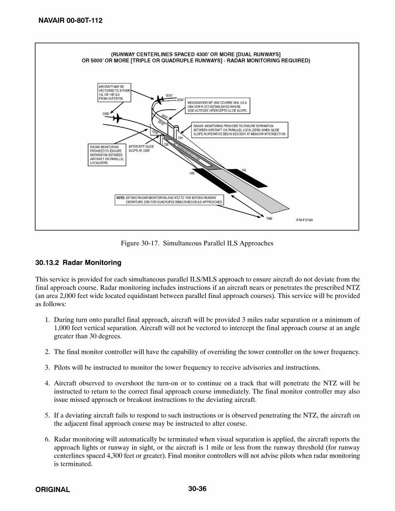
NAVAIR 00-80T-112
ORIGINAL 30-36
Figure 30-17. Simultaneous Parallel ILS Approaches
30.13.2 Radar Monitoring
This service is provided for each simultaneous parallel ILS/MLS approach to ensure aircraft do not deviate from thefinal approach course. Radar monitoring includes instructions if an aircraft nears or penetrates the prescribed NTZ(an area 2,000 feet wide located equidistant between parallel final approach courses). This service will be providedas follows:
1. During turn onto parallel final approach, aircraft will be provided 3 miles radar separation or a minimum of1,000 feet vertical separation. Aircraft will not be vectored to intercept the final approach course at an anglegreater than 30 degrees.
2. The final monitor controller will have the capability of overriding the tower controller on the tower frequency.
3. Pilots will be instructed to monitor the tower frequency to receive advisories and instructions.
4. Aircraft observed to overshoot the turn-on or to continue on a track that will penetrate the NTZ will beinstructed to return to the correct final approach course immediately. The final monitor controller may alsoissue missed approach or breakout instructions to the deviating aircraft.
5. If a deviating aircraft fails to respond to such instructions or is observed penetrating the NTZ, the aircraft onthe adjacent final approach course may be instructed to alter course.
6. Radar monitoring will automatically be terminated when visual separation is applied, the aircraft reports theapproach lights or runway in sight, or the aircraft is 1 mile or less from the runway threshold (for runwaycenterlines spaced 4,300 feet or greater). Final monitor controllers will not advise pilots when radar monitoringis terminated.

NAVAIR 00-80T-112
ORIGINAL30-37
30.14 SIMULTANEOUS CLOSE PARALLEL ILS PRM APPROACHES (INDEPENDENT)
30.14.1 System
This approach system permits simultaneous ILS PRM approaches (Figure 30-18) to dual runways with centerlinesseparated by less than 4,300 feet and equipped with final monitor controllers. To qualify for reduced lateral runwayseparation, final monitor controllers must be equipped with high-update radar and high-resolution ATC radardisplays, collectively called a PRM system. The PRM system displays almost instantaneous radar information.Automated tracking software provides monitor controllers with aircraft identification, position, a 10-secondprojected position, as well as visual and aural controller alerts. The PRM system is a supplemental requirement forsimultaneous close parallel approaches in addition to the system requirements for simultaneous parallel ILS/MLSapproaches described in paragraph 30.13. Simultaneous close parallel ILS PRM approaches are identified by aseparate approach procedure chart named ILS PRM (Simultaneous Close Parallel). The name ILS PRM is derivedfrom the Precision Runway Monitor System (PRMS), which provides a means for simplifying the name of thesimultaneous close parallel ILS approach.
30.14.2 Requirements
The following requirements must be met in order to fly an ILS PRM approach:
1. Air carrier pilots (including Part 121 and Part 135) must complete ILS PRM training, which includes viewingone of the FAA videos, RDU Precision Runway Monitor: A Pilot’s Approach or ILS PRM Approaches,Information for Pilots. Watching one of these videos is strongly recommended for all pilots who wish to flythese approaches.
2. All ATC-directed breakouts, a vector off the ILS prior to the DA, must be hand flown.
3. If the airport has two tower frequencies operating for each runway, the aircraft flying the ILS PRM approachmust have the capability of enabling the pilot(s) to listen to two frequencies simultaneously. Pilots shall adviseair traffic control within 200 miles of the airport of intended landing if the pilot(s) are not qualified and/or theaircraft is not equipped to fly the approach.
30.14.3 Radar Monitoring
Simultaneous close parallel ILS/MLS approaches require final monitor controllers utilize the Precision RunwayMonitor System (PRMS) to ensure prescribed separation standards are met. Procedures and communicationsphraseology are described in paragraph 30.13. To ensure separation is maintained, and in order to avoid an imminentsituation during simultaneous close parallel ILS/MLS approaches, pilots must immediately comply with finalmonitor controller instructions to avoid an imminent situation. A minimum of 3 miles radar separation or 1,000 feetvertical separation will be provided during the turn onto close parallel final approach courses. In the event of a missedapproach, radar monitoring is provided to one-half mile beyond the departure end of the runway. Final monitorcontrollers will not notify pilots when radar monitoring is terminated.

NAVAIR 00-80T-112
ORIGINAL 30-38
Figure 30-18. ILS PRM Approaches
30.14.4 Differences Between ILS and ILS PRM Approaches of Importance to the Pilot
30.14.4.1 Runway Spacing
Prior to ILS PRM approaches, most ATC-directed breakouts were the result of two aircraft in trail getting too closetogether. Two aircraft going in the same direction did not mandate quick reaction times, but two aircraft along sideeach other separated by less than 4,300 feet and closing at 135 feet per second does constitute the need for quick action.A blunder has to be recognized by one controller, the information passed on to another controller, and breakoutinstructions issued to the endangered aircraft. The pilot will not have any warning that a breakout is imminent becausethe blundering aircraft will probably be on another frequency. It is important that when a pilot receives breakoutinstructions, he/she assumes that a blundering aircraft is heading into his/her approach course and begins the breakoutas soon as safety allows.
30.14.4.2 Communications
To help in avoiding communication problems caused by stuck mikes and two parties talking at the same time, twotower frequencies for each runway will be in use during ILS PRM approach operations. The tower controller and themonitor controller will be broadcasting on both of the assigned frequencies. The monitor controller has the capabilityof overriding the tower controller. The pilots flying the approach will listen to both frequencies and only broadcaston the primary tower frequency. If a breakout is initiated by the monitor controller and the primary frequency isblocked by another transmission, the breakout instruction will be able to be heard on the second frequency.Antiblocking technology installed in VHF radios might remove the requirement for the second VHF communicationsfrequency in the near future.

NAVAIR 00-80T-112
ORIGINAL30-39
30.14.4.3 Hand-Flown Breakouts
The use of the autopilot is encouraged while flying an ILS PRM approach, but the autopilot must be disengaged inthe rare event that a breakout is issued. Simulation studies of breakouts have shown that a hand-flown breakout isinitiated consistently faster than a breakout performed using the autopilot.
30.14.4.4 TCAS
TCAS II-equipped aircraft will fly the ILS PRM approach with the TCAS set to the Traffic Advisory (TA) only mode.If the TCAS is set to the TA/Resolution Advisory (RA) mode, there is a chance that the TCAS resolution advisorywill be in conflict with the breakout instruction and result in a confusing situation during a critical time. Pilots mustremember to switch back to the TA/RA mode after completing the breakout maneuver.
30.14.4.5 Descending Breakouts
In the past, breakout descents were rarely given to pilots when flying on the lLS localizer and glideslope. A greaterchance exists for the controller to issue a descending breakout when there is a blundering aircraft from an adjacentapproach course crossing an aircraft path. Pilots must be aware that a descending breakout is a possibility. In no casewill the controller descend an aircraft below the Minimum Vectoring Altitude (MVA), which will provide at least1,000 feet clearance above obstacles. The pilot is not expected to exceed 1,000 feet per minute rate of descent in theevent a descending breakout is issued.
30.15 SIMULTANEOUS CONVERGING INSTRUMENT APPROACHES
ATC may conduct instrument approaches simultaneously to converging runways (i.e., runways having an includedangle from 15 to 100 degrees) at airports where a program has been specifically approved to do so.
The basic concept requires that dedicated, separate standard instrument approach procedures be developed for eachconverging runway included. Missed approach points must be at least 3 miles apart and missed approach proceduresensure missed approach protected airspace does not overlap.
Other requirements are radar availability, nonintersecting final approach courses, precision (ILS/MLS) approachsystems on each runway and, if runways intersect, controllers must be able to apply visual separation as well asintersecting runway separation criteria. Intersecting runways also require minimums of at least 700-foot ceilings and2 miles visibility. Straight-in approaches and landings must be made.
Whenever simultaneous converging approaches are in progress, aircraft will be informed by the controller as soonas feasible after initial contact or via ATIS. Additionally, the radar controller will have direct communicationscapability with the tower controller where separation responsibility has not been delegated to the tower.
30.16 SIDESTEP MANEUVER
ATC may authorize a nonprecision approach procedure that serves either one of parallel runways that are separatedby 1,200 feet or less followed by a straight-in landing on the adjacent runway.
Aircraft that will execute a sidestep maneuver will be cleared for a specified nonprecision approach and landing onthe adjacent parallel runway (e.g., “cleared ILS runway 7 left approach, sidestep to runway 7 right”). Pilots areexpected to commence the sidestep maneuver as soon as possible after the runway or runway environment is in sight.
Landing minimums to the adjacent runway will be based on nonprecision criteria and therefore higher than theprecision minimums to the primary runway, but will normally be lower than the published circling minimums.
30.17 APPROACH AND LANDING MINIMUMS
30.17.1 Landing Minimums
The rules applicable to landing minimums are contained in 14 CFR Section 91.175.

NAVAIR 00-80T-112
ORIGINAL 30-40
30.17.2 Published Approach Minimums
Approach minimums are published for different aircraft categories and consist of a minimum altitude (DA, DH,MDA) and required visibility. These minimums are determined by applying the appropriate TERPS criteria. Whena fix is incorporated in a nonprecision final segment, two sets of minimums may be published: one for the pilot whois able to identify the fix and a second for the pilot who cannot. Two sets of minimums may also be published whena second altimeter source is used in the procedure. When a nonprecision procedure incorporates both a stepdown fixin the final segment and a second altimeter source, two sets of minimums are published to account for the stepdownfix and a note addresses minimums for the second altimeter source.
30.17.3 Obstacle Clearance
Final approach obstacle clearance is provided from the start of the final segment to the runway or missed approachpoint, whichever occurs last. Sidestep obstacle protection is provided by increasing the width of the final approachobstacle clearance area. Circling approach protected areas are defined by the tangential connection of arcs drawn fromeach runway end. The arc radii distance differs by aircraft approach category. Because of obstacles near the airport,a portion of the circling area may be restricted by a procedural note (e.g., “Circling NA E of RWY 17-35”). Obstacleclearance is provided at the published minimums for the pilot who makes a straight-in approach, sidesteps, circles,or executes the missed approach. Missed approach obstacle clearance requirements may dictate the publishedminimums for the approach (Figure 30-19).
30.17.4 Straight-In Minimums
Straight-in minimums are shown on the IAP when the final approach course is within 30 degrees of the runwayalignment (15 degrees for GPS IAPs) and a normal descent can be made from the IFR altitude shown on the IAP tothe runway surface. When either the normal rate of descent or the runway alignment factor of 30 degrees (15 degreesfor GPS IAPs) is exceeded, a straight-in minimum is not published and a circling minimum applies. The fact that astraight-in minimum is not published does not preclude pilots from landing straight-in if they have the active runwayin sight and have sufficient time to make a normal approach for landing. Under such conditions and when ATC hascleared them for landing on that runway, pilots are not expected to circle even though only circling minimums arepublished. If they desire to circle, they should advise ATC.
30.17.5 Sidestep Maneuver Minimums
Landing minimums for a sidestep maneuver to the adjacent runway will normally be higher than the minimums tothe primary runway.
30.17.6 Circling Minimums
In some busy terminal areas, ATC may not allow circling and circling minimums will not be published. Publishedcircling minimums provide obstacle clearance when pilots remain within the appropriate area of protection. Pilotsshould remain at or above the circling altitude until the aircraft is continuously in a position from which a descentto a landing on the intended runway can be made at a normal rate of descent using normal maneuvers. Circling mayrequire maneuvers at low altitude, at low airspeed, and in marginal weather conditions. Pilots must use soundjudgment, have an in-depth knowledge of their capabilities, and fully understand the aircraft performance todetermine the exact circling maneuver because weather, unique airport design, and the aircraft position, altitude, andairspeed must all be considered. The following basic rules apply:
1. Maneuver the shortest path to the base or downwind leg, as appropriate, considering existing weatherconditions. There is no restriction from passing over the airport or other runways.
2. It should be recognized that circling maneuvers may be made while VFR or other flying is in progress at theairport. Standard left turns or specific instruction from the controller for maneuvering must be considered whencircling to land.

NAVAIR 00-80T-112
ORIGINAL30-41
Figure 30-19. Final Approach Obstacle Clearance
NAVAIR 00-80T-112
ORIGINAL 30-42
3. At airports without a control tower, it may be desirable to fly over the airport to observe wind and turn indicatorsand other traffic that may be on the runway or flying in the vicinity of the airport.
30.17.7 Instrument Approach at a Military Field
When instrument approaches are conducted by civil aircraft at military airports, they shall be conducted in accordancewith the procedures and minimums approved by the military agency having jurisdiction over the airport.
30.18 MISSED APPROACH
When a landing cannot be accomplished, advise ATC and, upon reaching the missed approach point defined on theapproach procedure chart, the pilot must comply with the missed approach instructions for the procedure being usedor with an alternate missed approach procedure specified by ATC.
Protected obstacle clearance areas for missed approach are predicated on the assumption that the missed approachis initiated at the DH or at the missed approach point and not lower than MDA. A climb of at least 200 feet per nauticalmile is required, unless a higher climb gradient is published on the approach chart. Reasonable buffers are providedfor normal maneuvers, but no consideration is given to an abnormally early turn; therefore, when an early missedapproach is executed, pilots should, unless otherwise cleared by ATC, fly the IAP as specified on the approach plateto the missed approach point at or above the MDA or DH before executing a turning maneuver.
If visual reference is lost while circling to land from an instrument approach, the missed approach specified for thatparticular procedure must be followed (unless an alternate missed approach procedure is specified by ATC). Tobecome established on the prescribed missed approach course, the pilot should make an initial climbing turn towardthe landing runway and continue the turn until established on the missed approach course. Inasmuch as the circlingmaneuver may be accomplished in more than one direction, different patterns will be required to become establishedon the prescribed missed approach course, depending on the aircraft position at the time visual reference is lost.Adherence to the procedure will ensure an aircraft will remain within the circling and missed approach obstructionclearance areas (Figure 30-20).
At locations where ATC radar service is provided, the pilot should conform to radar vectors when provided by ATCin lieu of the published missed approach procedure (Figure 30-21).
When approach has been missed, request clearance for specific action (e.g., to alternative airport, another approach,etc.).
30.19 VISUAL APPROACH
A visual approach is conducted on an IFR flight plan and authorizes a pilot to proceed visually and clear of cloudsto the airport. The pilot must have either the airport or the preceding identified aircraft in sight. This approach mustbe authorized and controlled by the appropriate air traffic control facility. Reported weather at the airport must havea ceiling at or above 1,000 feet and visibility 3 miles or greater. ATC may authorize this type approach when it willbe operationally beneficial. Visual approaches are an IFR procedure conducted under IFR in Visual MeteorologicalConditions (VMC). Cloud clearance requirements of 14 CFR Section 91.155 are not applicable, unless required byoperation specifications.
30.19.1 Operating to an Airport Without Weather Reporting Service
ATC will advise the pilot when weather information is not available at the destination airport. ATC may initiate avisual approach, provided there is a reasonable assurance that weather at the airport is a ceiling at or above 1,000 feetand visibility 3 miles or greater (e.g., area weather reports, Pilot Reports [PIREPs], etc.).

NAVAIR 00-80T-112
ORIGINAL30-43
Figure 30-20. Circling and Missed Approach Obstruction Clearance Areas
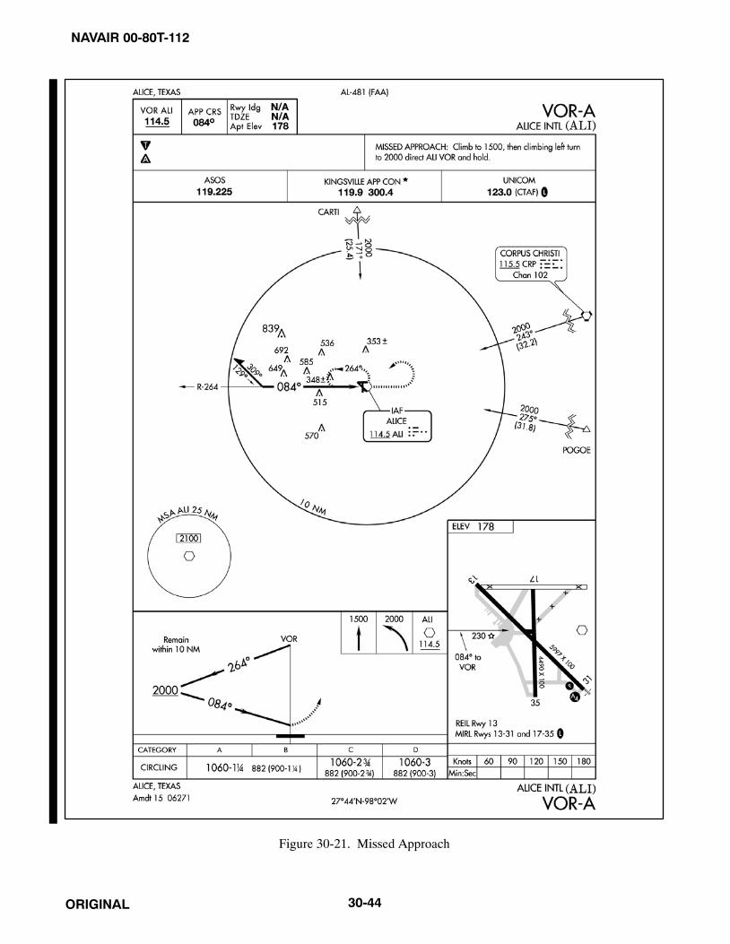
NAVAIR 00-80T-112
ORIGINAL 30-44
Figure 30-21. Missed Approach

NAVAIR 00-80T-112
ORIGINAL30-45
30.19.2 Operating to an Airport With an Operating Control Tower
Aircraft may be authorized to conduct a visual approach to one runway while other aircraft are conducting IFR orVFR approaches to another parallel, intersecting, or converging runway. When operating to airports with parallelrunways separated by less than 2,500 feet, the succeeding aircraft must report sighting the preceding aircraft unlessstandard separation is being provided by ATC. When operating to parallel runways separated by at least 2,500 feetbut less than 4,300 feet, controllers will clear/vector aircraft to the final at an angle not greater than 30 degrees unlessradar, vertical, or visual separation is provided during the turn-on. The purpose of the 30-degree intercept angle isto reduce the potential for overshoots of the final and to preclude side-by-side operations with one or both aircraftin a belly-up configuration during the turn-on. Once the aircraft are established within 30 degrees of final, or on thefinal, these operations may be conducted simultaneously. When the parallel runways are separated by 4,300 feet ormore, or intersecting/converging runways are in use, ATC may authorize a visual approach after advising all aircraftinvolved that other aircraft are conducting operations to the other runway. This may be accomplished through useof the ATIS.
30.19.3 Separation Responsibilities
If the pilot has the airport in sight but cannot see the aircraft to be followed, ATC may clear the aircraft for a visualapproach; however, ATC retains both separation and wake vortex separation responsibility. When visually followinga preceding aircraft, acceptance of the visual approach clearance constitutes acceptance of pilot responsibility formaintaining a safe approach interval and adequate wake turbulence separation.
A visual approach is not an IAP and therefore has no missed approach segment. If a go-around is necessary for anyreason, aircraft operating at controlled airports will be issued an appropriate advisory/clearance/instruction by thetower. At uncontrolled airports, aircraft are expected to remain clear of clouds and complete a landing as soon aspossible. If a landing cannot be accomplished, the aircraft is expected to remain clear of clouds and contact ATC assoon as possible for further clearance. Separation from other IFR aircraft will be maintained under thesecircumstances.
Visual approaches reduce pilot/controller workload and expedite traffic by shortening flightpaths to the airport. It isthe pilot’s responsibility to advise ATC as soon as possible if a visual approach is not desired.
Authorization to conduct a visual approach is an IFR authorization and does not alter IFR flight plan cancellationresponsibility.
Radar service is automatically terminated, without advising the pilot, when the aircraft is instructed to change toadvisory frequency.
30.20 CHARTED VISUAL FLIGHT PROCEDURE (CVFP)
CVFPs are charted visual approaches established for environmental/noise considerations and/or when necessary forthe safety and efficiency of air traffic operations. The approach charts depict prominent landmarks, courses, andrecommended altitudes to specific runways. CVFPs are designed to be used primarily for turbojet aircraft.
These procedures will be used only at airports with an operating control tower.
Most approach charts will depict some NAVAID information, which is for supplemental navigational guidance only.
Unless indicating a Class B airspace floor, all depicted altitudes are for noise abatement purposes and arerecommended only. Pilots are not prohibited from flying other-than-recommended altitudes if operationalrequirements dictate.
When landmarks used for navigation are not visible at night, the approach will be annotated “PROCEDURE NOTAUTHORIZED AT NIGHT.”

NAVAIR 00-80T-112
ORIGINAL 30-46
CVFPs usually begin within 20 flying miles from the airport.
Published weather minimums for CVFPs are based on minimum vectoring altitudes rather than the recommendedaltitudes depicted on charts.
CVFPs are not instrument approaches and do not have missed approach segments.
ATC will not issue clearances for CVFPs when the weather is less than the published minimum.
ATC will clear aircraft for a CVFP after the pilot reports siting a charted landmark or a preceding aircraft. If instructedto follow a preceding aircraft, pilots are responsible for maintaining a safe approach interval and wake turbulenceseparation.
Pilots should advise ATC if at any point they are unable to continue an approach or lose sight of a preceding aircraft.Missed approaches will be handled as a go-around.
30.21 CONTACT APPROACH
Pilots operating in accordance with an IFR flight plan, provided they are clear of clouds and have at least 1 mile flightvisibility and can reasonably expect to continue to the destination airport in those conditions, may request ATCauthorization for a contact approach.
Controllers may authorize a contact approach provided:
1. The contact approach is specifically requested by the pilot. ATC cannot initiate this approach.
2. The reported ground visibility at the destination airport is at least 1 statute mile.
3. The contact approach will be made to an airport having a standard or special instrument approach procedure.
4. Approved separation is applied between aircraft so cleared and between these aircraft and other IFR or specialVFR aircraft.
A contact approach is an approach procedure that may be used by a pilot (with prior authorization from ATC) in lieuof conducting a standard or special IAP to an airport. It is not intended for use by a pilot on an IFR flight clearanceto operate to an airport not having a published and functioning IAP, nor is it intended for an aircraft to conduct aninstrument approach to one airport and then, when “in the clear,” discontinue that approach and proceed to anotherairport. In the execution of a contact approach, the pilot assumes the responsibility for obstruction clearance. If radarservice is being received, it will automatically terminate when the pilot is instructed to change to advisory frequency.
30.22 LANDING PRIORITY
A clearance for a specific type of approach (ILS, MLS, ADF, VOR, or straight in) to an aircraft operating on an IFRflight plan does not mean that landing priority will be given over other traffic. Airport Traffic Control Towers (ATCTs)handle all aircraft, regardless of the type of flight plan, on a first-come, first-served basis; therefore, because of localtraffic or runway in use, it may be necessary for the controller, in the interest of safety, to provide a different landingsequence. In any case, a landing sequence will be issued to each aircraft as soon as possible to enable the pilot toproperly adjust the aircraft flightpath.
30.23 OVERHEAD APPROACH MANEUVER
Pilots operating in accordance with an IFR flight plan in VMC may request ATC authorization for an overheadmaneuver. An overhead maneuver is not an instrument approach procedure. Overhead maneuver patterns are

NAVAIR 00-80T-112
ORIGINAL30-47
developed at airports where aircraft have an operational need to conduct the maneuver. An aircraft conducting anoverhead maneuver is considered to be VFR and the IFR flight plan is canceled when the aircraft reaches the initialpoint on the initial approach portion of the maneuver (Figure 30-22). The existence of a standard overhead maneuverpattern does not eliminate the possible requirement for an aircraft to conform to conventional rectangular patternsif an overhead maneuver cannot be approved. Aircraft operating to an airport without a functioning control tower mustinitiate cancellation of an IFR flight plan prior to executing the overhead maneuver. Cancellation of the IFR flightplan must be accomplished after crossing the landing threshold on the initial portion of the maneuver or after landing.Controllers may authorize an overhead maneuver and issue the following to arriving aircraft:
1. Pattern altitude and direction of traffic. This information may be omitted if either is standard.
2. Request for a report on initial approach.
3. Break information and a request for the pilot to report. The break point will be specified if nonstandard. Pilotsmay be requested to report break if required for traffic or other reasons.
30.24 APPROACH LIGHT SYSTEM (ALS)
The ALS provides the basic means to transition from instrument flight to visual flight for landing. Operationalrequirements dictate the sophistication and configuration of the approach light system for a particular runway.
The ALS is a configuration of signal lights starting at the landing threshold and extending into the approach area adistance of 2,400 to 3,000 feet for precision instrument runways and 1,400 to 1,500 feet for nonprecision instrumentrunways. Some systems include sequenced flashing lights, which appear to the pilot as a ball of light traveling towardthe runway at high speed (twice a second) (Figure 30-23).
Figure 30-22. Overhead Maneuver

NAVAIR 00-80T-112
ORIGINAL 30-48
Figure 30-23. Precision and Nonprecision Configuration (Lighting)

NAVAIR 00-80T-112
ORIGINAL30-49
30.25 VISUAL GLIDESLOPE INDICATORS
30.25.1 Visual Approach Slope Indicator (VASI)
The Visual Approach Slope Indicator (VASI) is a system of lights so arranged to provide visual descent guidanceinformation during the approach to a runway. These lights are visible from 3 to 5 miles during the day and up to 20miles or more at night. The visual glidepath of the VASI provides safe obstruction clearance within ±10 degrees ofthe extended runway centerline and to 4 nm from the runway threshold. Descent, using the VASI, should not beinitiated until the aircraft is visually aligned with the runway. Lateral course guidance is provided by the runway orrunway lights.
VASI installations may consist of 2, 4, 6, 12, or 16 light units arranged in bars referred to as near, middle, and far bars.Most VASI installations consist of 2 bars, near and far, and may consist of 2, 4, or 12 light units. Some VASIs consistof three bars (near, middle, and far), which provide an additional visual glidepath to accommodate high-cockpitaircraft. This installation may consist of either 6 or 16 light units. VASI installations consisting of 2, 4, or 6 light unitsare located on one side of the runway, usually the left. Where the installation consists of 12 or 16 light units, the unitsare located on both sides of the runway.
Two-bar VASI installations provide one visual glidepath, which is normally set at 3 degrees. Three-bar VASIinstallations provide two visual glidepaths. The lower glidepath is provided by the near and middle bars and isnormally set at 3 degrees whereas the upper glidepath, provided by the middle and far bars, is normally 1/4 degreehigher. This higher glidepath is intended for use only by high-cockpit aircraft to provide a sufficient threshold crossingheight. Although normal glidepath angles are 3 degrees, angles at some locations may be as high as 4.5 degrees togive proper obstacle clearance. Pilots of high-performance aircraft are cautioned that use of VASI angles in excessof 3.5 degrees may cause an increase in runway length required for landing and rollout.
The basic principle of the VASI is that of color differentiation between red and white. Each light unit projects a beamof light having a white segment in the upper part of the beam and red segment in the lower part of the beam. The lightunits are arranged so that the pilot using the VASIs during an approach will see the combination of lights shown below.
For 28-bar VASI (4 light units), Figure 30-24.
For 3-bar VASI (6 light units), Figure 30-25.
For other VASI configurations, Figure 30-26.
30.25.2 Precision Approach Path Indicator (PAPI)
The PAPI uses light units similar to the VASI but are installed in a single row of either two or four light units. Thesesystems have an effective visual range of approximately 5 miles during the day and up to 20 miles at night. The rowof light units is normally installed on the left side of the runway and the glidepath indications are as depicted(Figure 30-27).
30.25.3 Tricolor Systems
Tricolor visual approach slope indicators normally consist of a single light unit projecting a three-color visualapproach path into the final approach area of the runway upon which the indicator is installed. The below-glidepathindication is red, the above-glidepath indication is amber, and the on-glidepath indication is green. These types ofindicators have a useful range of approximately one-half to 1 mile during the day and up to 5 miles at night dependingupon the visibility conditions (Figure 30-28).

NAVAIR 00-80T-112
ORIGINAL 30-50
Figure 30-24. 28-Bar VASI
Figure 30-25. 3-Bar VASI
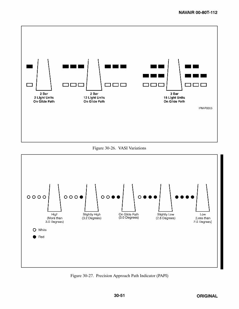
NAVAIR 00-80T-112
ORIGINAL30-51
Figure 30-26. VASI Variations
(3.0 Degrees)
Figure 30-27. Precision Approach Path Indicator (PAPI)

NAVAIR 00-80T-112
ORIGINAL 30-52
Figure 30-28. Tricolor Visual Approach Slope Indicator
Note� Since the tricolor VASI consists of a single light source that could possibly
be confused with other light sources, pilots should exercise care to properlylocate and identify the light signal.
� When the aircraft descends from green to red, the pilot may see a darkamber color during the transition from green to red.
30.25.4 Pulsating Systems
Pulsating visual approach slope indicators normally consist of a single light unit projecting a two-color visualapproach path into the final approach area of the runway upon which the indicator is installed. The on-glidepathindication is a steady white light. The slightly-below-glidepath indication is a steady red light. If the aircraft descendsfurther below the glidepath, the red light starts to pulsate. The above-glidepath indication is a pulsating white light.The pulsating rate increases as the aircraft gets farther above or below the desired glideslope. The useful range of thesystem is approximately 4 miles during the day and up to 10 miles at night (Figure 30-29).
NoteSince the PVASI consists of a single light source that could possibly beconfused with other light sources, pilots should exercise care to properlylocate and identify the light signal.

NAVAIR 00-80T-112
ORIGINAL30-53
Figure 30-29. Pulsating Visual Approach Slope Indicator
30.25.5 Alignment of Elements Systems
Alignment of elements systems are installed on some small general aviation airports and are a low-cost systemconsisting of painted plywood panels, normally black and white or fluorescent orange. Some of these systems arelighted for night use. The useful range of these systems is approximately three-quarters of a mile. To use the system,the pilot positions the aircraft so the elements are in alignment. The glidepath indications are shown in Figure 30-30.
30.26 RUNWAY END IDENTIFIER LIGHTS (REIL)
REILs are installed at many airfields to provide rapid and positive identification of the approach end of a particularrunway. The system consists of a pair of synchronized flashing lights located laterally on each side of the runwaythreshold. REILs may be either omnidirectional or unidirectional facing the approach area. They are effective for:
1. Identification of a runway surrounded by a preponderance of other lighting.
2. Identification of a runway that lacks contrast with surrounding terrain.
3. Identification of a runway during reduced visibility.
30.27 RUNWAY EDGE LIGHT SYSTEMS
Runway edge lights are used to outline the edges of runways during periods of darkness or restricted visibilityconditions. These light systems are classified according to the intensity or brightness they are capable of producing:they are the High Intensity Runway Lighting (HIRL), Medium Intensity Runway Lighting (MIRL), and the LowIntensity Runway Lighting (LIRL). The HIRL and MIRL systems have variable intensity controls, whereas the LIRLsnormally have one intensity setting.

NAVAIR 00-80T-112
ORIGINAL 30-54
Figure 30-30. Alignment of Elements
The runway edge lights are white, except on instrument runways, where yellow replaces white on the last 2,000 feetor half the runway length, whichever is less, to form a caution zone for landings.
The lights marking the ends of the runway emit red light toward the runway to indicate the end of runway to a departingaircraft and emit green outward from the runway end to indicate the threshold to landing aircraft.
30.28 IN-RUNWAY LIGHTING
30.28.1 Runway Centerline Lighting System (RCLS)
Runway centerline lights are installed on some precision approach runways to facilitate landing under adversevisibility conditions. They are located along the runway centerline and are spaced at 50-foot intervals. When viewedfrom the landing threshold, the runway centerline lights are white until the last 3,000 feet of the runway. The whitelights begin to alternate with red for the next 2,000 feet, and for the last 1,000 feet of the runway, all centerline lightsare red.
30.28.2 Touchdown Zone Lights (TDZL)
Touchdown zone lights are installed on some precision approach runways to indicate the touchdown zone whenlanding under adverse visibility conditions. They consist of two rows of transverse light bars disposed symmetricallyabout the runway centerline. The system consists of steady-burning white lights that start 100 feet beyond the landingthreshold and extend to 3,000 feet beyond the landing threshold or to the midpoint of the runway, whichever is less.
30.28.3 Taxiway Lead-Off Lights
Taxiway lead-off lights extend from the runway centerline to a point on an exit taxiway to expedite movement ofaircraft from the runway. These lights alternate green and yellow from the runway centerline to the runway holdingposition or the ILS/MLS critical area, as appropriate.

NAVAIR 00-80T-112
ORIGINAL30-55
30.28.4 Land and Hold Short Lights
Land and hold short lights are used to indicate the hold short point on certain runways that are approved for Land andHold Short Operations (LAHSO). Land and hold short lights consist of a row of pulsing white lights installed acrossthe runway at the hold short point. Where installed, the lights will be on anytime LAHSO is in effect. These lightswill be off when LAHSO is not in effect. Reference Aeronautical Information Manual (AIM), Pilot ResponsibilitiesWhen Conducting Land and Hold Short Operations (LAHSO).
30.29 CONTROL OF LIGHTING SYSTEMS
Operation of approach light systems and runway lighting is controlled by the control tower (ATCT). At somelocations, the FSS may control the lights where there is no control tower in operation.
Pilots may request that lights be turned on or off. Runway edge lights, in-pavement lights, and approach lights alsohave intensity controls that may be varied to meet the pilot’s request. Sequenced Flashing Lights (SFL) may be turnedon and off. Some sequenced flashing light systems also have intensity control.
30.30 PILOT CONTROL OF AIRPORT LIGHTING
Radio control of lighting is available at selected airports to provide airborne control of lights by keying the aircraftmicrophone. Control of lighting systems is often available at locations without specified hours for lighting and wherethere is no control tower or FSS or when the tower or FSS is closed (locations with a part-time tower or FSS) orspecified hours. All lighting systems that are radio controlled at an airport, whether on a single runway or multiplerunways, operate on the same radio frequency (Figures 30-31 and 30-32).
Lighting SystemNo. of Int.
StepsStatus DuringNonuse Period
Intensity Step Selected Per No. of Mike Clicks
3 Clicks 5 Clicks 7 Clicks
Approach Lights(Med. Int.) 2 Off Low Low High
Approach Lights(Med. Int.) 3 Off Low Med High
MIRL 3 Off or Low • • •
HIRL 5 Off or Low • • •
VASI 2 Off * * *
NOTES:• Predetermined intensity step.
* Low intensity for night use. High intensity for day use as determined by photocell control.
Figure 30-31. Runways with Approach Lights

NAVAIR 00-80T-112
ORIGINAL 30-56
Lighting SystemNo. of Int.
StepsStatus DuringNonuse Period
Intensity Step Selected Per No. of Mike Clicks
3 Clicks 5 Clicks 7 Clicks
MIRL 3 Off or Low Low Med. High
HIRL 5 Off or Low Step1 or 2 Step 3 Step 5
LIRL 1 Off On On On
VASIL* 2 Off • • •
REIL* 1 Off Off On/Off On
REIL* 3 Off Low Med. High
NOTES:• Low intensity for night use. High intensity for day use as determined by photocell control.
* The control of VASIL and/or REIL may be independent of other lighting systems.
Figure 30-32. Runways without Approach Lights
With FAA-approved systems, various combinations of medium-intensity approach lights, runway lights, taxiwaylights, VASI, and/or REIL may be activated by radio control. On runways with both approach lighting and runwaylighting (runway edge lights, taxiway lights, etc.) systems, the approach lighting system takes precedence forair-to-ground radio control over the runway lighting system, which is set at a predetermined intensity step, based onexpected visibility conditions. Runways without approach lighting may provide radio-controlled intensityadjustments of runway edge lights. Other lighting systems, including VASI, REIL, and taxiway lights, may either becontrolled with the runway edge lights or controlled independently of the runway edge lights.
The control system consists of a 3-step control responsive to 7, 5, and/or 3 microphone clicks. This 3-step controlwill turn on lighting facilities capable of either 3-step, 28-step, or 1-step operation. The 3-step and 28-step lightingfacilities can be altered in intensity, whereas the 1-step cannot. All lighting is illuminated for a period of 15 minutesfrom the most recent time of activation and may not be extinguished prior to end of the 15-minute period (except for1-step and 28-step REILs, which may be turned off when desired by keying the mike 5 or 3 times, respectively).
Suggested use is always to key the mike 7 times initially; this ensures all controlled lights are turned on to themaximum available intensity. If desired, adjustment can then be made, where the capability is provided, to a lowerintensity (or the REIL turned off) by keying 5 and/or 3 times. Due to the close proximity of airports using the samefrequency, radio-controlled lighting receivers may be set at a low sensitivity requiring the aircraft to be relatively closeto activate the system. Consequently, even when lights are on, always key mike as directed when overflying an airportof intended landing or just prior to entering the final segment of an approach. This will ensure the aircraft is closeenough to activate the system and a full 15 minutes lighting duration is available. Approved lighting systems maybe activated by keying the mike (within 5 seconds) as indicated below:
Radio Control System
Key Mike Function
7 times within 5 seconds Highest intensity available
5 times within 5 seconds Medium or lower intensity (Lower REIL or REIL off)
3 times within 5 seconds Lowest intensity available (Lower REIL or REIL off)
For all public use airports with FAA standard systems, the Airport/Facility Directory contains the types of lighting,runway, and the frequency that is used to activate the system. Airports with IAPs include data on the approach chartidentifying the light system, the runway on which they are installed, and the frequency that is used to activate thesystem.

NAVAIR 00-80T-112
ORIGINAL30-57
NoteAlthough the CTAF is used to activate the lights at many airports, otherfrequencies may also be used. The appropriate frequency for activating thelights on the airport is provided in the Airport/Facility Directory and thestandard instrument approach procedures publications. It is not identifiedon the sectional charts.
Where the airport is not served by an IAP, it may have either the standard FAA-approved control system or anindependent type system of different specification installed by the airport sponsor. The Airport/Facility Directorycontains descriptions of pilot-controlled lighting systems for each airport having other-than-FAA-approved systemsand explains the type lights, method of control, and operating frequency in clear text.
30.31 AIRPORT/HELIPORT BEACONS
Airport and heliport beacons have a vertical light distribution to make them most effective from 1 to 10 degrees abovethe horizon; however, they can be seen well above and below this peak spread. The beacon may be an omnidirectionalcapacitor-discharge device, or it may rotate at a constant speed, which produces the visual effect of flashes at regularintervals. Flashes may be one or two colors alternately. The total number of flashes are:
1. 24 to 30 per minute for beacons marking airports, landmarks, and points on Federal airways.
2. 30 to 45 per minute for beacons marking heliports.
The colors and color combinations of beacons are:
1. White and green — lighted land airport.
2. *Green alone — lighted land airport.
3. White and yellow — lighted water airport.
4. *Yellow alone — lighted water airport.
5. Green, yellow, and white — lighted heliport.
Note*Green alone or yellow alone is used only in connection with awhite-and-green or white-and-yellow beacon display, respectively.
Military airport beacons flash alternately white and green, but are differentiated from civil beacons by dual-peaked(two quick) white flashes between the green flashes.
In Class B, Class C, Class D, and Class E surface areas, operation of the airport beacon during the hours of daylightoften indicates the ground visibility is less than 3 miles and/or the ceiling is less than 1,000 feet. ATC clearance inaccordance with 14 CFR Part 91 is required for landing, takeoff, and flight in the traffic pattern. Pilots should not relysolely on the operation of the airport beacon to indicate if weather conditions are IFR or VFR. At some locations withoperating control towers, ATC personnel turn the beacon on or off when controllers are in the tower. At many airports,the airport beacon is turned on by a photoelectric cell or time clocks and ATC personnel cannot control them. Thereis no regulatory requirement for daylight operation and it is the pilot’s responsibility to comply with proper preflightplanning as required by 14 CFR Section 91.103.
30.32 TAXIWAY LIGHTS
30.32.1 Taxiway Edge Lights
Taxiway edge lights are used to outline the edges of taxiways during periods of darkness or restricted visibilityconditions. These fixtures emit blue light.

NAVAIR 00-80T-112
ORIGINAL 30-58
Note
At most major airports, these lights have variable intensity settings and maybe adjusted at pilot request or when deemed necessary by the controller.
30.32.2 Taxiway Centerline Lights
Taxiway centerline lights are used to facilitate ground traffic under low visibility conditions. They are located alongthe taxiway centerline in a straight line on straight portions, on the centerline of curved portions, and along designatedtaxiing paths in portions of runways, ramps, and apron areas. Taxiway centerline lights are steady burning and emitgreen light.
30.32.3 Clearance Bar Lights
Clearance bar lights are installed at holding positions on taxiways in order to increase the conspicuity of the holdingposition in low visibility conditions. They may also be installed to indicate the location of an intersecting taxiwayduring periods of darkness. Clearance bars consist of three in-pavement steady-burning yellow lights.
30.32.4 Runway Guard Lights
Runway guard lights are installed at taxiway/runway intersections. They are primarily used to enhance theconspicuity of taxiway/runway intersections during low visibility conditions, but may be used in all weatherconditions. Runway guard lights consist of either a pair of elevated flashing yellow lights installed on either side ofthe taxiway or a row of in-pavement yellow lights installed across the entire taxiway at the runway holding positionmarking.
Note
Some airports may have a row of three or five in-pavement yellow lightsinstalled at taxiway/runway intersections. They should not be confusedwith clearance bar lights described in paragraph 30.32.3.
30.32.5 Stop Bar Lights
Stop bar lights, when installed, are used to confirm the ATC clearance to enter or cross the active runway in lowvisibility conditions (below 1,200 feet runway visual range). A stop bar consists of a row of red, unidirectional,steady-burning in-pavement lights installed across the entire taxiway at the runway holding position and elevatedsteady-burning red lights on each side. A controlled stop bar is operated in conjunction with the taxiway centerlinelead-on lights, which extend from the stop bar toward the runway. Following the ATC clearance to proceed, the stopbar is turned off and the lead-on lights are turned on. The stop bar and lead-on lights are automatically reset by a sensoror backup timer.
CAUTION
Pilots should never cross a red illuminated stop bar, even if an ATCclearance has been given to proceed onto or across the runway.
Note
If, after crossing a stop bar, the taxiway centerline lead-on lightsinadvertently extinguish, pilots should hold their position and contact ATCfor further instructions.

NAVAIR 00-80T-112
ORIGINAL81/(82 blank)
PART VIII
Indoctrination and Flight Evaluation
Chapter 31 — The Instrument Flight Evaluation

NAVAIR 00-80T-112
ORIGINAL1/(2 blank)
NAVAIR 00-80T-112
ORIGINAL31-1
CHAPTER 31
The Instrument Flight Evaluation
31.1 PURPOSE OF THE INSTRUMENT FLIGHT EVALUATION
Maintaining a high degree of instrument flight proficiency is basic to safe and effective flight operations and essentialfor meeting unit all-weather operational commitments. The NATOPS instrument flight evaluation program wasestablished to assist the commanding officer in maintaining a high level of all-weather flying proficiency in his unit.Instrument flight procedures contained in this manual represent the optimum methods for training for and performingthe various maneuvers that will be required for Instrument Flight Rules (IFR) flight. The NATOPS instrumentevaluation is intended to evaluate the pilot’s knowledge and application of these procedures and techniques duringflight operations in instrument weather conditions.
31.2 REQUIREMENTS FOR INSTRUMENT FLIGHT EVALUATIONS
Together, OPNAVINST 3710.7 and this manual contain the elements that compose the NATOPS evaluation program.The requirements and administrative procedures for NATOPS instrument flight evaluations are contained inOPNAVINST 3710.7 series. The conduct, content, and grading criteria for these instrument evaluations, whichcompliment the information contained OPNAVINST 3710.7, are contained in this chapter. If conflicts developbetween the contents in this manual and OPNAVINST 3710.7 series, the requirements in OPNAVINST 3710.7 seriesshall take precedence.
31.3 THE INSTRUMENT FLIGHT EVALUATION PROCESS
The instrument flight evaluation process requires completion of a formal TYCOM-approved ground training syllabus(if available), a ground evaluation, and a flight evaluation.
31.3.1 Instrument Ground Training
OPNAVINST 3710.7 series requires that all pilots and Naval Flight Officers (NFOs) in DIFOPS status shall completea formal TYCOM-approved ground training syllabus (if one is available). In addition to the subjects normallyaddressed during the instrument ground and flight evaluations and listed below, the ground training syllabus shallinclude any additional ground training subjects listed in OPNAVINST 3710.7 series.
31.3.2 Instrument Ground Evaluation
Incident to the completion of instrument ground training (if utilized) and prior to the evaluation flight, pilots andNFOs shall satisfactorily complete an approved written examination. The written examination may be open bookor closed book or both. In addition to any subjects listed for coverage during the ground training and writtenexamination evaluation phases in OPNAVINST 3710.7 series, the written examination shall include questions onthe following subjects:
1. Pertinent Navy regulations, orders, and instructions.
2. Pertinent parts of the Federal aviation regulations, other regulations, and/or aeronautical publications that areapplicable.
3. Interpretation of weather information normally used in flight planning.

NAVAIR 00-80T-112
ORIGINAL 31-2
The written examination should emphasize air traffic control procedures that have been issued or revised during thepreceding year. The written examination shall be completed with a grade of “Qualified,” in accordance withOPNAVINST 3710.7 series, prior to the commencement of the instrument evaluation flight.
31.3.3 Instrument Flight Evaluation
Following completion of the ground evaluation, an instrument flight evaluation shall be flown and completed witha grade of “Qualified.” The number of flights required to complete the instrument flight evaluation should be keptto a minimum — normally one flight. Areas to be observed and graded on an evaluation flight are outlined in thegrading criteria. The instrument flight evaluation shall consist of two parts. Part One covers basic instrument flying,and Part Two covers the planning and conduct of a flight under actual or simulated instrument conditions in controlledairspace. Flight evaluations may be in an aircraft or an approved flight simulator. Instrument flight checks underactual instrument conditions are encouraged.
31.3.3.1 Basic Instrument Flying (Part One)
Part One of the instrument flight evaluation shall consist of:
1. Instrument takeoff (optional).
*2. Climbing, descending, and timed turns.
*3. Steep turns.
*4. Recovery from unusual attitudes.
5. Positioning aircraft on predetermined VHF Omnidirectional Range (VOR)/Tactical Air Navigation (TACAN)radial.
*6. Partial panel airwork.
7. ADF orientation.
a. ADF/Manual Direction Finder (MDF) for pilots operating in areas where radio beacons are the primary orsecondary means of instrument navigation.
b. Ultrahigh Frequency (UHF)/ADF for jet aircraft.
NoteAsterisked items above are not required when the evaluation is conductedunder actual instrument conditions.
31.3.3.2 Instrument Flight in Controlled Airspace (Part Two)
Part Two of the instrument evaluation shall consist of:
1. Airways flight — The pilot shall be required to take off and proceed to a destination in accordance with anAir Traffic Control (ATC) clearance and execute an appropriate published instrument approach, utilizing theavailable and pertinent navigation facilities. If weather and other conditions permit, the pilot shall be requiredto execute approaches (including ILS/radar or GPS) and missed approaches as applicable, utilizing as manyof the existing navigation aids as practicable. The use of VOR/TACAN shall be emphasized when feasible.
2. The pilot shall demonstrate a thorough working knowledge of the operation and use of all installedcommunications and navigation equipment.

NAVAIR 00-80T-112
ORIGINAL31-3
3. The pilot shall demonstrate ability to cope with any emergency situation that might logically be expected tooccur on an instrument flight, for example:
a. Engine failure.
b. Instrument failure.
c. Communications failure.
d. Navigation equipment failure.
31.4 FLIGHT EVALUATION GRADING CRITERIA
The criteria for determining area adjective grades are outlined in the following paragraphs.
31.4.1 Basic Instrument Flying (Part One) Grading Criteria
31.4.1.1 Instrument Takeoff
31.4.1.1.1 Qualified
Receives and acknowledges ATC clearances. Executes engine runup and instrument checks. Brake release is smoothand good directional control is maintained. Liftoff is accomplished as required to a positive climbing attitude andacceleration to climb schedule is expeditiously and safely accomplished.
31.4.1.1.2 Unqualified
Does not receive and acknowledge takeoff clearance, causing unnecessary delay or traffic disruption. Exhibits pooror unsafe technique in directional control, liftoff, transition, climb attitude, or in establishing climb schedule.
31.4.1.2 Climbing, Descending, and Timed Turns
31.4.1.2.1 Qualified
Smoothly transitions to an angle of bank that approximates that required for the desired rate of turn. Adjusts angleof bank as required to maintain desired rate of turn. Maintains relatively constant turn throughout maneuver.
31.4.1.2.2 Unqualified
Transition to angle of bank indicates a lack of knowledge of procedure and technique or results in an unsafe maneuver.Exhibits poor or unsafe technique in attaining desired rate of turn. Does not maintain a relatively constant turnthroughout maneuver.
31.4.1.3 Steep Turns
31.4.1.3.1 Qualified
Maintains positive control and applies proper correction to keep within safe limits of altitude and airspeed.
31.4.1.3.2 Unqualified
Exhibits poor or unsafe control. Allows altitude and airspeed to exceed safe limits.

NAVAIR 00-80T-112
ORIGINAL 31-4
31.4.1.4 Recovery from Unusual Attitudes
31.4.1.4.1 Qualified
Demonstrates proper procedure for recovery from unusual attitudes.
31.4.1.4.2 Unqualified
Not familiar with proper procedures for recovery from unusual attitudes.
31.4.1.5 VOR/TACAN Positioning
31.4.1.5.1 Qualified
Demonstrates proper procedures for positioning aircraft on predetermined VOR/TACAN radial.
31.4.1.5.2 Unqualified
Not familiar with proper procedures for positioning aircraft on predetermined VOR/TACAN radial.
31.4.1.6 Partial Panel Airwork
31.4.1.6.1 Qualified
Maintains control and applies proper corrections to keep within safe limits of altitude, airspeed, attitude, and heading.
31.4.1.6.2 Unqualified
Exhibits poor or unsafe control. Exceeds safe limits of altitude, airspeed, attitude, or heading.
31.4.1.7 ADF/MDF Orientation
31.4.1.7.1 Qualified
Demonstrates proper procedures for aural null/ADF orientation.
31.4.1.7.2 Unqualified
Not familiar with proper procedures for aural null/ADF orientation.
31.4.2 Instrument Flight in Controlled Airspace (Part Two) Grading Criteria
31.4.2.1 Flight Planning
31.4.2.1.1 Qualified
Flight plan and clearance executed in accordance with LOCAL, Flight Information Publications (FLIP), OPNAV,and other governing instructions. Special factors, as required by the mission or aircraft configuration, are computedand recorded where applicable. Completes flight planning log for route without major errors. Fuel consumption isproperly computed based upon available planning factors and recorded on the flight log. Ensures that maps and chartsfor route, destination, and alternate are available and are current. Weather factors, temperatures and winds aloftinformation, and Notices to Airmen (NOTAMs) are used in planning the mission. Standard Instrument Departure(SID)/IFR departure procedures and routes are obtained, if required, and takeoff/climb planned accordingly.
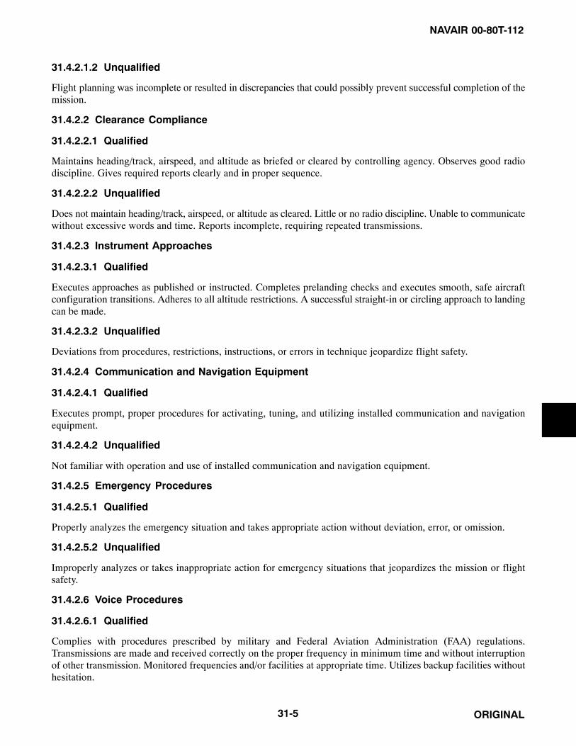
NAVAIR 00-80T-112
ORIGINAL31-5
31.4.2.1.2 Unqualified
Flight planning was incomplete or resulted in discrepancies that could possibly prevent successful completion of themission.
31.4.2.2 Clearance Compliance
31.4.2.2.1 Qualified
Maintains heading/track, airspeed, and altitude as briefed or cleared by controlling agency. Observes good radiodiscipline. Gives required reports clearly and in proper sequence.
31.4.2.2.2 Unqualified
Does not maintain heading/track, airspeed, or altitude as cleared. Little or no radio discipline. Unable to communicatewithout excessive words and time. Reports incomplete, requiring repeated transmissions.
31.4.2.3 Instrument Approaches
31.4.2.3.1 Qualified
Executes approaches as published or instructed. Completes prelanding checks and executes smooth, safe aircraftconfiguration transitions. Adheres to all altitude restrictions. A successful straight-in or circling approach to landingcan be made.
31.4.2.3.2 Unqualified
Deviations from procedures, restrictions, instructions, or errors in technique jeopardize flight safety.
31.4.2.4 Communication and Navigation Equipment
31.4.2.4.1 Qualified
Executes prompt, proper procedures for activating, tuning, and utilizing installed communication and navigationequipment.
31.4.2.4.2 Unqualified
Not familiar with operation and use of installed communication and navigation equipment.
31.4.2.5 Emergency Procedures
31.4.2.5.1 Qualified
Properly analyzes the emergency situation and takes appropriate action without deviation, error, or omission.
31.4.2.5.2 Unqualified
Improperly analyzes or takes inappropriate action for emergency situations that jeopardizes the mission or flightsafety.
31.4.2.6 Voice Procedures
31.4.2.6.1 Qualified
Complies with procedures prescribed by military and Federal Aviation Administration (FAA) regulations.Transmissions are made and received correctly on the proper frequency in minimum time and without interruptionof other transmission. Monitored frequencies and/or facilities at appropriate time. Utilizes backup facilities withouthesitation.

NAVAIR 00-80T-112
ORIGINAL 31-6
31.4.2.6.2 Unqualified
Fails to transmit or receive mandatory reports through omission or lack of familiarity with procedures. Any violationof military/FAA regulations. Any violation of safety.
31.4.3 Flight Evaluation Grade Determination
All areas on the instrument flight evaluation are critical. An unsatisfactory grade in any area shall result in anunsatisfactory grade for the flight.
31.5 INSTRUMENT EVALUATION FINAL GRADE DETERMINATION
The final NATOPS instrument evaluation grade shall be the same as the grade assigned for the flight evaluation. Anevaluee who receives an “Unqualified” grade on the ground or flight evaluation shall be placed in an “Unqualified”instrument flight status until the evaluee achieves a grade of “Qualified” on a reevaluation.
31.6 RECORDS AND REPORTS
A NATOPS Instrument Rating Request OPNAV Form 3710/2 shall be completed for each evaluation and forwardedto the evaluee’s commanding officer. When completed, this form shall be retained in the individual’s flight trainingrecord. In addition, an entry shall be made in the pilot’s/NFO’s flight log book under “Qualifications andAchievements” as follows:
QUALIFICATION
Standard (or) special instrument rating.
Exp. (expiration date) DATE (Date issued).
SIGNATURE (Authenticating signature) (Unit issuing rating).
31.7 MAINTAINING ALL-WEATHER READINESS
NATOPS instrument evaluations, combined with a unit training syllabus that includes periodic flights to maintainthese skills, will help each unit prepare for and remain ready to safely and successfully meet its all-weathercommitments.

NAVAIR 00-80T-112
ORIGINALA-1/(A-2 blank)
APPENDIX A
References
A.1 PURPOSE
As discussed in Chapter 1, this appendix lists publication series that contain additional information related toinstrument flight. These publications are listed in Figure A-1 below.
Pub Number or Author Pub Title and Other Significant Information
AFM 11-217V1 USAF Instrument Flight Manual
BUMEDINST 6410.9 Medical Monitoring Flight Personnel in Locations Where Flight Surgeons are not Available
FAA Order 7110.65 Air Traffic Control
MIL-DTL-85025 (AS) Draft NATOPS Program Technical Publications and Products; Style, Format, and Common Technical Content
NAVAIR 00-80T-105 CV NATOPS Manual
NAVAIR 00-80T-106 LHA/LHD NATOPS Manual
NAVAIR 00-80T-111 V/STOL Shipboard and Landing Signal Officer NATOPS Manual
NAVAIR 00-80T-113 NATOPS Aircraft Signals Manual
NAVAIR 00-80T-122 NATOPS Helicopter Operating Procedures For Air-Capable ShipsManual
NAVMED FM 6410/1 Aeromedical Grounding Notice
NAVMED FM 6410/2 Aeromedical Flight Clearance Notice
OPNAVINST 3710.7 NATOPS General Flight and Operating Instructions
OPNAVINST 6110.1 Physical Readiness Standards
FAA Aeronautical Information Manual
14 CFR Part 71 Airspace
14 CFR Part 91 General Operating and Flight Rules
Figure A-1. Other Publications Related to Instrument Flight

NAVAIR 00-80T-112
ORIGINALA-1/(A-2 blank)

NAVAIR 00-80T-112
ORIGINAL1
INDEX
PageNo.
PageNo.
A
Acceleration error 15-4 . . . . . . . . . . . . . . . . . . . . . . . . ACM or air-to-ground ordnance deliveries 9-2 . . . . . Additional reports 29-4 . . . . . . . . . . . . . . . . . . . . . . .
At all times 29-4 . . . . . . . . . . . . . . . . . . . . . . . . . . When not in radar contact 29-5 . . . . . . . . . . . . . . .
ADF:Homing procedures 23-10 . . . . . . . . . . . . . . . . . . . Procedure(s) 23-3 , 23-7 . . . . . . . . . . . . . . . . . . . .
Adherence to clearance 28-5 . . . . . . . . . . . . . . . . . . . Adjacent channel interference 22-6 . . . . . . . . . . . . . . Advance information on instrument
approach 30-3 . . . . . . . . . . . . . . . . . . . . . . . . . . . . . . Advection fog 6-8 . . . . . . . . . . . . . . . . . . . . . . . . . . . . Aileron roll 19-9 . . . . . . . . . . . . . . . . . . . . . . . . . . . . . Airborne equipment 24-4 . . . . . . . . . . . . . . . . . . . . . . Aircraft control 17-1 . . . . . . . . . . . . . . . . . . . . . . . . . .
Attitude control 17-2 . . . . . . . . . . . . . . . . . . . . . . . Aircraft icing 6-9 . . . . . . . . . . . . . . . . . . . . . . . . . . . .
Clear ice 6-9 . . . . . . . . . . . . . . . . . . . . . . . . . . . . . . Frost 6-9 . . . . . . . . . . . . . . . . . . . . . . . . . . . . . . . . . Rime ice 6-9 . . . . . . . . . . . . . . . . . . . . . . . . . . . . . . Structural icing 6-9 . . . . . . . . . . . . . . . . . . . . . . . .
Aircraft trim 17-9 . . . . . . . . . . . . . . . . . . . . . . . . . . . . Aircraft:
Control 17-1 . . . . . . . . . . . . . . . . . . . . . . . . . . . . . . Dual-seat 12-2 . . . . . . . . . . . . . . . . . . . . . . . . . . . . Engine icing 6-11 . . . . . . . . . . . . . . . . . . . . . . . . . . Multicrewed 12-2 . . . . . . . . . . . . . . . . . . . . . . . . . . Single-seat 12-1 . . . . . . . . . . . . . . . . . . . . . . . . . . . Trim 17-9 . . . . . . . . . . . . . . . . . . . . . . . . . . . . . . . .
Aircrew actions 26-10 . . . . . . . . . . . . . . . . . . . . . . . . Approach procedures 26-12 . . . . . . . . . . . . . . . . . . Be prepared to use traditional
NAVAIDs 26-11 . . . . . . . . . . . . . . . . . . . . . . . . . . En route operations 26-11 . . . . . . . . . . . . . . . . . . . Preflight 26-10 . . . . . . . . . . . . . . . . . . . . . . . . . . . . Prior to descent 26-11 . . . . . . . . . . . . . . . . . . . . . . Terminal area operations and arrival 26-11 . . . . . .
Terminal area operations and departure 26-10 . . . . . . . . . . . . . . . . . . . . . . . . . .
Airfoil 6-10 . . . . . . . . . . . . . . . . . . . . . . . . . . . . . . . . . Airmass:
Classification 3-1 . . . . . . . . . . . . . . . . . . . . . . . . . . Development 3-1 . . . . . . . . . . . . . . . . . . . . . . . . . . Modification 3-1 . . . . . . . . . . . . . . . . . . . . . . . . . . Thunderstorms 6-3 . . . . . . . . . . . . . . . . . . . . . . . . . Weather 3-2 . . . . . . . . . . . . . . . . . . . . . . . . . . . . . .
AIRMETs 27-4 . . . . . . . . . . . . . . . . . . . . . . . . . . . . . . Airport/heliport beacons 30-57 . . . . . . . . . . . . . . . . . Airspeed(s) 29-11 . . . . . . . . . . . . . . . . . . . . . . . . . . . .
Control 18-11 , 18-16 . . . . . . . . . . . . . . . . . . . . . . . Indicator 15-4 . . . . . . . . . . . . . . . . . . . . . . . . . . . . .
Airway(s):And jet routes depiction on flight plan 27-6 . . . . . Or route course changes 29-7 . . . . . . . . . . . . . . . . .
Airways and route systems 29-5 . . . . . . . . . . . . . . . . Area navigation (RNAV) routes 29-6 . . . . . . . . . . Radar vectors 29-6 . . . . . . . . . . . . . . . . . . . . . . . . .
Alignment of elements systems 30-53 . . . . . . . . . . . . Alternate:
Airport restrictions 26-9 . . . . . . . . . . . . . . . . . . . . . Navigation equipment 26-9 . . . . . . . . . . . . . . . . . .
RNAV procedural speed restrictions 26-9 . . . . . Altimeters 16-1 . . . . . . . . . . . . . . . . . . . . . . . . . . . . . . Altitude:
Control 18-16 . . . . . . . . . . . . . . . . . . . . . . . . . . . . . Data 28-2 . . . . . . . . . . . . . . . . . . . . . . . . . . . . . . . . Stabilization 18-16 . . . . . . . . . . . . . . . . . . . . . . . . .
Amended clearances 28-3 . . . . . . . . . . . . . . . . . . . . . . Angle of attack indicator 15-8 . . . . . . . . . . . . . . . . . . Application
Planning 18-1 . . . . . . . . . . . . . . . . . . . . . . . . . . . . . Approach and landing minimums 30-39 . . . . . . . . . .
Circling minimums 30-40 . . . . . . . . . . . . . . . . . . . Instrument approach at a military field 30-42 . . . . Landing minimums 30-39 . . . . . . . . . . . . . . . . . . . Obstacle clearance 30-40 . . . . . . . . . . . . . . . . . . . . Published approach minimums 30-40 . . . . . . . . . . Sidestep maneuver minimums 30-40 . . . . . . . . . . . Straight-in minimums 30-40 . . . . . . . . . . . . . . . . .
Index-1

NAVAIR 00-80T-112
ORIGINAL 2
PageNo.
PageNo.
Approach control 30-2 . . . . . . . . . . . . . . . . . . . . . . . . Radar approach control 30-2 . . . . . . . . . . . . . . . . .
Approach(es):Advance information on instrument 30-3 . . . . . . . Clearance 30-26 . . . . . . . . . . . . . . . . . . . . . . . . . . . Contact 30-46 . . . . . . . . . . . . . . . . . . . . . . . . . . . . . Dual-facility 21-36 . . . . . . . . . . . . . . . . . . . . . . . . . Final 26-13 . . . . . . . . . . . . . . . . . . . . . . . . . . . . . . . From holding 21-42 . . . . . . . . . . . . . . . . . . . . . . . . GPS overlay 26-9 . . . . . . . . . . . . . . . . . . . . . . . . . . GPS stand-alone 26-9 . . . . . . . . . . . . . . . . . . . . . . High-altitude penetration and 22-18 . . . . . . . . . . . Holding type 21-42 . . . . . . . . . . . . . . . . . . . . . . . . Light systems (ALS) 30-47 . . . . . . . . . . . . . . . . . . Localizer 24-10 . . . . . . . . . . . . . . . . . . . . . . . . . . . Localizer (LOC) back course 24-11 . . . . . . . . . . . . Low-altitude 22-20 . . . . . . . . . . . . . . . . . . . . . . . . . Missed 30-42 . . . . . . . . . . . . . . . . . . . . . . . . . . . . . Non-DME teardrop 21-34 . . . . . . . . . . . . . . . . . . . Performing the ILS 24-5 . . . . . . . . . . . . . . . . . . . . Performing the missed 26-13 . . . . . . . . . . . . . . . . . Pilot operational considerations when
flying nonprecision 30-21 . . . . . . . . . . . . . . . . . . Precision final 25-4 . . . . . . . . . . . . . . . . . . . . . . . . Procedures 23-14 , 26-12 . . . . . . . . . . . . . . . . . . . Radar 25-3 , 30-30 . . . . . . . . . . . . . . . . . . . . . . . . Radar monitoring of instrument 30-33 . . . . . . . . . Simultaneous converging instrument 30-39 . . . . . Straight-in 21-36 . . . . . . . . . . . . . . . . . . . . . . . . . . Surveillance final 25-6 . . . . . . . . . . . . . . . . . . . . . . Vertical descent angle (VDA) on
nonprecision 30-21 . . . . . . . . . . . . . . . . . . . . . . . Visual 30-42 . . . . . . . . . . . . . . . . . . . . . . . . . . . . . .
Arc interceptions 22-10 . . . . . . . . . . . . . . . . . . . . . . . Arctic fog 6-8 . . . . . . . . . . . . . . . . . . . . . . . . . . . . . . . Area navigation (RNAV) 27-8 , 29-6 , 30-22 . . . . . .
Instrument approach charts 30-22 . . . . . . . . . . . . . Routes 29-6 . . . . . . . . . . . . . . . . . . . . . . . . . . . . . .
AreaRNAV in the terminal 26-8 . . . . . . . . . . . . . . . . . .
ARTCC communications 29-1 . . . . . . . . . . . . . . . . . . ARTCC radio frequency outage 29-2 . . . . . . . . . . ATC frequency change procedures 29-1 . . . . . . . .
Direct communications, controllers and pilots 29-1 . . . . . . . . . . . . . . . . . . . . . . . . . . .
ATC:Clearance/instruction readback 28-4 . . . . . . . . . . . Frequency change procedures 29-1 . . . . . . . . . . . .
Attitude:Control 17-2 , 18-16 . . . . . . . . . . . . . . . . . . . . . . . Indicator failure 18-18 . . . . . . . . . . . . . . . . . . . . . . Interpretation 20-2 . . . . . . . . . . . . . . . . . . . . . . . . . Stabilization 18-15 . . . . . . . . . . . . . . . . . . . . . . . . .
Automatic direction finding (ADF):Course interceptions 23-3 . . . . . . . . . . . . . . . . . . . Procedures 23-1 . . . . . . . . . . . . . . . . . . . . . . . . . . . Station passage 23-3 . . . . . . . . . . . . . . . . . . . . . . . Tuning 23-2 . . . . . . . . . . . . . . . . . . . . . . . . . . . . . .
Aviation severe weather warning bulletins (WWs) 27-2 . . . . . . . . . . . . . . . . . . . . . . . .
Azimuth cone of confusion 22-6 . . . . . . . . . . . . . . . .
B
Bank control 17-2 . . . . . . . . . . . . . . . . . . . . . . . . . . . . Barrel roll 19-7 . . . . . . . . . . . . . . . . . . . . . . . . . . . . . . Basic instrument flying (part one)
grading criteria 31-3 . . . . . . . . . . . . . . . . . . . . . . . . . ADF/MDF orientation 31-4 . . . . . . . . . . . . . . . . . . Climbing, descending, and timed turns 31-3 . . . . . Instrument takeoff 31-3 . . . . . . . . . . . . . . . . . . . . . Partial panel airwork 31-4 . . . . . . . . . . . . . . . . . . . Recovery from unusual attitudes 31-4 . . . . . . . . . . Steep turns 31-3 . . . . . . . . . . . . . . . . . . . . . . . . . . . VOR/TACAN positioning 31-4 . . . . . . . . . . . . . . .
Be prepared to use traditional NAVAIDs 26-11 . . . . . Be wary of “heads-down” 26-11 . . . . . . . . . . . . . . . . Bearing indicators:
Bearing-distance-heading indicator (BDHI) 16-6 . . . . . . . . . . . . . . . . . . . . .
Horizontal situation indicator (HSI) 16-6 . . . . . . . Radio magnetic indicator (RMI) 16-6 . . . . . . . . . .
Bearing-distance-heading indicator (BDHI) 16-6 . . . . . . . . . . . . . . . . . . . . . . .
Bearing/distance “unlock” 22-5 . . . . . . . . . . . . . . . . . Before takeoff 28-9 . . . . . . . . . . . . . . . . . . . . . . . . . . . Blood donation 10-2 . . . . . . . . . . . . . . . . . . . . . . . . . . BRAVO pattern 19-6 . . . . . . . . . . . . . . . . . . . . . . . . .
Index-2

NAVAIR 00-80T-112
ORIGINAL3
PageNo.
PageNo.
C
Canceling IFR flight plan 27-11 . . . . . . . . . . . . . . . . CDI only 21-6 . . . . . . . . . . . . . . . . . . . . . . . . . . . . . . Change:
In flight plan 27-11 . . . . . . . . . . . . . . . . . . . . . . . . In proposed departure time 27-11 . . . . . . . . . . . . .
Changeover point (COP) 29-8 . . . . . . . . . . . . . . . . . . Characteristics:
TACAN 22-5 . . . . . . . . . . . . . . . . . . . . . . . . . . . . . CHARLIE pattern 19-5 . . . . . . . . . . . . . . . . . . . . . . . Charts:
Area navigation (RNAV) instrument approach 30-22 . . . . . . . . . . . . . . . . . . . . . . . . . .
Instrument approach procedure 30-4 . . . . . . . . . . . Check NOTAMs 26-10 . . . . . . . . . . . . . . . . . . . . . . . Clear ice 6-9 . . . . . . . . . . . . . . . . . . . . . . . . . . . . . . . . Clear-air turbulence 6-7 . . . . . . . . . . . . . . . . . . . . . . . Clearance 28-1 . . . . . . . . . . . . . . . . . . . . . . . . . . . . . .
Bar lights 30-58 . . . . . . . . . . . . . . . . . . . . . . . . . . . Limit 28-1 . . . . . . . . . . . . . . . . . . . . . . . . . . . . . . . Prefix 28-1 . . . . . . . . . . . . . . . . . . . . . . . . . . . . . . .
Clearance items 28-1 . . . . . . . . . . . . . . . . . . . . . . . . . Altitude data 28-2 . . . . . . . . . . . . . . . . . . . . . . . . . Clearance limit 28-1 . . . . . . . . . . . . . . . . . . . . . . . . Departure procedure 28-1 . . . . . . . . . . . . . . . . . . . Holding instructions 28-2 . . . . . . . . . . . . . . . . . . . Route of flight 28-2 . . . . . . . . . . . . . . . . . . . . . . . .
Climbing:And descending turns 18-15 . . . . . . . . . . . . . . . . . Constant rate climbs and descents 18-14 . . . . . . . .
Climbs and descent(s) 28-9 . . . . . . . . . . . . . . . . . . . . Constant airspeed climbs and descents 18-12 . . . . Constant-rate climbs and descents 18-14 . . . . . . . .
Clock 15-8 . . . . . . . . . . . . . . . . . . . . . . . . . . . . . . . . . Closing VFR/DVFR flight plans 27-11 . . . . . . . . . . . Cold fronts 4-1 . . . . . . . . . . . . . . . . . . . . . . . . . . . . . .
Thunderstorms 6-4 . . . . . . . . . . . . . . . . . . . . . . . . . Communications 30-38 . . . . . . . . . . . . . . . . . . . . . . . Compasses:
Acceleration error 15-4 . . . . . . . . . . . . . . . . . . . . . Deviation 15-3 . . . . . . . . . . . . . . . . . . . . . . . . . . . . Magnetic dip 15-3 . . . . . . . . . . . . . . . . . . . . . . . . . Oscillation error 15-4 . . . . . . . . . . . . . . . . . . . . . . .
Standby magnetic compass 15-1 . . . . . . . . . . . . . . Variation 15-1 . . . . . . . . . . . . . . . . . . . . . . . . . . . . .
Completing the intercept 21-17 , 23-7 . . . . . . . . . . . Concept:
Airmass classification 3-1 . . . . . . . . . . . . . . . . . . . Airmass development 3-1 . . . . . . . . . . . . . . . . . . . Airmass modification 3-1 . . . . . . . . . . . . . . . . . . . Airmass weather 3-2 . . . . . . . . . . . . . . . . . . . . . . .
Confidence maneuvers:Aileron roll 19-9 . . . . . . . . . . . . . . . . . . . . . . . . . . Barrel roll 19-7 . . . . . . . . . . . . . . . . . . . . . . . . . . . . Half Cuban eight 19-11 . . . . . . . . . . . . . . . . . . . . . Immelmann 19-11 . . . . . . . . . . . . . . . . . . . . . . . . . Loops 19-9 . . . . . . . . . . . . . . . . . . . . . . . . . . . . . . . Wingover 19-7 . . . . . . . . . . . . . . . . . . . . . . . . . . . .
Confusion of ground lights with stars 8-9 . . . . . . . . . Constant:
Airspeed climbs and descents 18-12 . . . . . . . . . . . Rate climbs and descents 18-14 . . . . . . . . . . . . . . .
Contact approach 30-46 . . . . . . . . . . . . . . . . . . . . . . . Control:
Aircraft 17-1 . . . . . . . . . . . . . . . . . . . . . . . . . . . . . . Airspeed 18-16 . . . . . . . . . . . . . . . . . . . . . . . . . . . . Altitude 18-16 . . . . . . . . . . . . . . . . . . . . . . . . . . . . Approach 30-2 . . . . . . . . . . . . . . . . . . . . . . . . . . . . Attitude 17-2 . . . . . . . . . . . . . . . . . . . . . . . . . . . . . Bank 17-2 . . . . . . . . . . . . . . . . . . . . . . . . . . . . . . . . Instruments 17-4 . . . . . . . . . . . . . . . . . . . . . . . . . . Of lighting systems 30-55 . . . . . . . . . . . . . . . . . . . Panel 21-2 . . . . . . . . . . . . . . . . . . . . . . . . . . . . . . . Pitch 17-2 . . . . . . . . . . . . . . . . . . . . . . . . . . . . . . . . Power 18-16 . . . . . . . . . . . . . . . . . . . . . . . . . . . . . . Radar approach 30-2 . . . . . . . . . . . . . . . . . . . . . . . Segment 26-1 . . . . . . . . . . . . . . . . . . . . . . . . . . . . . Yaw 17-2 . . . . . . . . . . . . . . . . . . . . . . . . . . . . . . . .
Convective:SIGMETs 27-3 . . . . . . . . . . . . . . . . . . . . . . . . . . . . Thunderstorms 6-3 . . . . . . . . . . . . . . . . . . . . . . . . . Wind shear 6-12 . . . . . . . . . . . . . . . . . . . . . . . . . . .
Conventional cross-check 14-3 . . . . . . . . . . . . . . . . . Convergence zones 5-2 . . . . . . . . . . . . . . . . . . . . . . . . Coriolis illusion 8-2 . . . . . . . . . . . . . . . . . . . . . . . . . . Correlation:
Under actual instrument conditions 11-1 , 11-2 , 11-3 . . . . . . . . . . . . . . .
Under instrument conditions 11-3 . . . . . . . . . . . . .
Index-3

NAVAIR 00-80T-112
ORIGINAL 4
PageNo.
PageNo.
Course indicator 16-10 . . . . . . . . . . . . . . . . . . . . . . . . ILS display 16-11 . . . . . . . . . . . . . . . . . . . . . . . . . . VOR/TACAN display 16-11 . . . . . . . . . . . . . . . . .
Course:Interceptions 21-4 , 23-3 . . . . . . . . . . . . . . . . . . . Sensitivity 26-4 . . . . . . . . . . . . . . . . . . . . . . . . . . .
Crosswind correction 21-33 . . . . . . . . . . . . . . . . . . . . Cumulus stage 6-1 . . . . . . . . . . . . . . . . . . . . . . . . . . .
D
Database:Requirements 26-8 . . . . . . . . . . . . . . . . . . . . . . . . . Restrictions 26-8 . . . . . . . . . . . . . . . . . . . . . . . . . .
Dental care 10-2 . . . . . . . . . . . . . . . . . . . . . . . . . . . . . Departure procedure 28-1 . . . . . . . . . . . . . . . . . . . . . . Descending breakouts 30-39 . . . . . . . . . . . . . . . . . . . Descent 21-42 . . . . . . . . . . . . . . . . . . . . . . . . . . . . . . . Develop a backup plan 26-11 . . . . . . . . . . . . . . . . . . . Deviation 15-3 . . . . . . . . . . . . . . . . . . . . . . . . . . . . . . Dial calibration 15-4 . . . . . . . . . . . . . . . . . . . . . . . . . . Differences between ILS and ILS PRM
approaches of importance to the pilot 30-38 . . . . . . Direct:
Communications, controllers and pilots 29-1 . . . . Entry procedure 29-12 . . . . . . . . . . . . . . . . . . . . . . Flights 27-7 . . . . . . . . . . . . . . . . . . . . . . . . . . . . . .
Display:ILS 16-11 . . . . . . . . . . . . . . . . . . . . . . . . . . . . . . . . VOR/TACAN 16-11 . . . . . . . . . . . . . . . . . . . . . . .
Dissipating stage 6-2 . . . . . . . . . . . . . . . . . . . . . . . . . Distance measuring equipment (DME) 22-3 . . . . . . . DME cone of confusion 22-6 . . . . . . . . . . . . . . . . . . . Drugs 10-1 . . . . . . . . . . . . . . . . . . . . . . . . . . . . . . . . . Dual-facility approaches 21-36 . . . . . . . . . . . . . . . . . Dual-seat aircraft 12-2 . . . . . . . . . . . . . . . . . . . . . . . .
E
Elevator illusion 8-6 . . . . . . . . . . . . . . . . . . . . . . . . . . Emergency procedures 31-5 . . . . . . . . . . . . . . . . . . . . En route:
Mode 26-5 . . . . . . . . . . . . . . . . . . . . . . . . . . . . . . . Operations 26-11 . . . . . . . . . . . . . . . . . . . . . . . . . .
Entry 21-39 . . . . . . . . . . . . . . . . . . . . . . . . . . . . . . . . . Procedures 29-12 . . . . . . . . . . . . . . . . . . . . . . . . . .
Environmental factors 9-1 . . . . . . . . . . . . . . . . . . . . . Equipment 21-1 . . . . . . . . . . . . . . . . . . . . . . . . . . . . .
Ground 22-2 . . . . . . . . . . . . . . . . . . . . . . . . . . . . . . Radar 25-2 . . . . . . . . . . . . . . . . . . . . . . . . . . . . . . .
Equipment and operation:Airborne equipment 24-4 . . . . . . . . . . . . . . . . . . . . Equipment 21-1 . . . . . . . . . . . . . . . . . . . . . . . . . . . Ground equipment 24-1 . . . . . . . . . . . . . . . . . . . . . Operation 21-2 . . . . . . . . . . . . . . . . . . . . . . . . . . . .
Equipment and transmission principles:Ground equipment 22-2 . . . . . . . . . . . . . . . . . . . . . TACAN approach procedures 22-18 . . . . . . . . . . . TACAN characteristics 22-5 . . . . . . . . . . . . . . . . . TACAN procedures 22-7 . . . . . . . . . . . . . . . . . . . .
Erroneous TACAN indications 22-6 . . . . . . . . . . . . . Establishing and maintaining airspeed 18-6 . . . . . . . Estimating drift correction 21-17 . . . . . . . . . . . . . . . . Exercise 10-1 . . . . . . . . . . . . . . . . . . . . . . . . . . . . . . . Experience 11-3 . . . . . . . . . . . . . . . . . . . . . . . . . . . . .
ACM or air-to-ground ordnance deliveries 9-2 . . . . . . . . . . . . . . . . . . . . . . . . . . . .
Takeoff and landing phases 9-1 . . . . . . . . . . . . . . .
F
Factors related to type or phase of flight:ACM or air-to-ground ordnance
deliveries 9-2 . . . . . . . . . . . . . . . . . . . . . . . . . . . . Formation flight 9-2 . . . . . . . . . . . . . . . . . . . . . . . . Takeoff and landing phases 9-1 . . . . . . . . . . . . . . .
Failure, indicator:Attitude 18-18 . . . . . . . . . . . . . . . . . . . . . . . . . . . . Heading 18-17 . . . . . . . . . . . . . . . . . . . . . . . . . . . .
False perception (general) 8-1 . . . . . . . . . . . . . . . . . . During helicopter flights 8-10 . . . . . . . . . . . . . . . . Illusions: primarily inner ear 8-1 . . . . . . . . . . . . . . Visual illusions and problems 8-9 . . . . . . . . . . . . .
False:Or incorrect lock-on 22-6 . . . . . . . . . . . . . . . . . . . . Perception of attitude 8-6 . . . . . . . . . . . . . . . . . . . . Perceptions during helicopter flights 8-10 . . . . . . . Sensation of reversal of motion 11-2 . . . . . . . . . . . Sensation of rotation 8-2 . . . . . . . . . . . . . . . . . . . .
Index-4

NAVAIR 00-80T-112
ORIGINAL5
PageNo.
PageNo.
Sensations of tilting to right or left 11-2 . . . . . . . .
Vertical and horizontal cues 8-9 . . . . . . . . . . . . . . .
Fast-moving cold fronts 4-3 . . . . . . . . . . . . . . . . . . . .
File the appropriate equipment suffix 26-10 . . . . . . .
Final:
Approach 26-13 . . . . . . . . . . . . . . . . . . . . . . . . . . .
Approach mode 26-7 . . . . . . . . . . . . . . . . . . . . . . .
Flicker vertigo 8-12 . . . . . . . . . . . . . . . . . . . . . . . . . .
Flight evaluation grade determination 31-6 . . . . . . . .
Flight evaluation grading criteria 31-3 . . . . . . . . . . . .
ADF/MDF orientation 31-4 . . . . . . . . . . . . . . . . . .
Basic instrument flying (part one) grading criteria 31-3 . . . . . . . . . . . . . . . . . . . . . . .
Clearance compliance 31-5 . . . . . . . . . . . . . . . . . .
Climbing, descending, and timed turns 31-3 . . . . .
Communication and navigation equipment 31-5 . . . . . . . . . . . . . . . . . . . . . . . . . .
Emergency procedures 31-5 . . . . . . . . . . . . . . . . . .
Flight evaluation grade determination 31-6 . . . . . .
Flight planning 31-4 . . . . . . . . . . . . . . . . . . . . . . .
Instrument approach(es) 31-5 . . . . . . . . . . . . . . . .
Instrument flight in controlled airspace (part two) grading criteria 31-4 . . . . . . . . . . . . . .
Instrument takeoff 31-3 . . . . . . . . . . . . . . . . . . . . .
Partial panel airwork 31-4 . . . . . . . . . . . . . . . . . . .
Recovery from unusual attitudes 31-4 . . . . . . . . . .
Steep turns 31-3 . . . . . . . . . . . . . . . . . . . . . . . . . . .
Voice procedures 31-5 . . . . . . . . . . . . . . . . . . . . . .
VOR/TACAN positioning 31-4 . . . . . . . . . . . . . . .
Flight management system (FMS) 26-2 . . . . . . . . . . .
Flight plan:
Composite (VFR/IFR flights) 27-5 . . . . . . . . . . . .
Defense VFR (DVFR) flights 27-5 . . . . . . . . . . . .
IFR flights 27-5 . . . . . . . . . . . . . . . . . . . . . . . . . . .
VFR flights 27-5 . . . . . . . . . . . . . . . . . . . . . . . . . .
Flight planning:
Preflight preparation 27-1 . . . . . . . . . . . . . . . . . . .
Weather briefing 27-1 . . . . . . . . . . . . . . . . . . . . . .
Weather briefing, support products, and severe weather restrictions and products 27-1 . . . . . . . . . . . . . . . . . . . . . . . . . . . .
Flight(s):Along a direct route 29-3 . . . . . . . . . . . . . . . . . . . . Along airways or routes 29-3 . . . . . . . . . . . . . . . . . Director system (FDS) 16-12 . . . . . . . . . . . . . . . . . In a radar environment 29-4 . . . . . . . . . . . . . . . . . . Outside the U.S. 27-10 . . . . . . . . . . . . . . . . . . . . . . Weather packets 27-2 . . . . . . . . . . . . . . . . . . . . . . .
Fog 6-7 . . . . . . . . . . . . . . . . . . . . . . . . . . . . . . . . . . . . Advection 6-8 . . . . . . . . . . . . . . . . . . . . . . . . . . . . . Arctic 6-8 . . . . . . . . . . . . . . . . . . . . . . . . . . . . . . . . Frontal 6-8 . . . . . . . . . . . . . . . . . . . . . . . . . . . . . . . Radiation 6-7 . . . . . . . . . . . . . . . . . . . . . . . . . . . . .
Follow IFR procedures even when operating VFR 27-4 . . . . . . . . . . . . . . . . . . . . . . . . .
Formation flight(s) 9-2 . . . . . . . . . . . . . . . . . . . . . . . . In night or weather 12-2 . . . . . . . . . . . . . . . . . . . . .
40° azimuth error lock-on 22-6 . . . . . . . . . . . . . . . . . Frontal movement 4-7 . . . . . . . . . . . . . . . . . . . . . . . .
Effect of mountains 4-7 . . . . . . . . . . . . . . . . . . . . . Modifications 4-7 . . . . . . . . . . . . . . . . . . . . . . . . . . Speed 4-7 . . . . . . . . . . . . . . . . . . . . . . . . . . . . . . . .
Frontal:Fog 6-8 . . . . . . . . . . . . . . . . . . . . . . . . . . . . . . . . . . Thunderstorms 6-4 . . . . . . . . . . . . . . . . . . . . . . . . .
Frost 6-9 . . . . . . . . . . . . . . . . . . . . . . . . . . . . . . . . . . . Functions of instruments − full panel scan 17-4 . . . . Future improvements to GPS 26-16 . . . . . . . . . . . . . .
Local area augmentation system (LAAS) 26-17 . . . . . . . . . . . . . . . . . . . . . . . . . . .
Wide area augmentation system (WAAS) 26-16 . . . . . . . . . . . . . . . . . . . . . . . . . . .
G
Glideslope 24-3 . . . . . . . . . . . . . . . . . . . . . . . . . . . . . Global orientation 14-1 . . . . . . . . . . . . . . . . . . . . . . . Global positioning system (GPS):
Flight management system (FMS) 26-2 . . . . . . . . Introduction 26-1 . . . . . . . . . . . . . . . . . . . . . . . . . . Required navigation performance
(RNP) 26-2 . . . . . . . . . . . . . . . . . . . . . . . . . . . . . . RNAV leg types 26-3 . . . . . . . . . . . . . . . . . . . . . . . System overview 26-1 . . . . . . . . . . . . . . . . . . . . . . Waypoints 26-3 . . . . . . . . . . . . . . . . . . . . . . . . . . .
Index-5

NAVAIR 00-80T-112
ORIGINAL 6
PageNo.
PageNo.
GPS approach nomenclature:Overlay approaches 26-9 . . . . . . . . . . . . . . . . . . . . RNAV (GPS) approaches 26-10 . . . . . . . . . . . . . . RNAV (RNP) approaches 26-10 . . . . . . . . . . . . . . Stand-alone approaches 26-9 . . . . . . . . . . . . . . . . .
GPS approach restrictions:Multiple GPS receivers 26-9 . . . . . . . . . . . . . . . . . RNAV procedural speed restrictions 26-9 . . . . . . . Scaling and alerting 26-9 . . . . . . . . . . . . . . . . . . . .
GPS navigation training:Flight training 26-15 . . . . . . . . . . . . . . . . . . . . . . . General 26-14 . . . . . . . . . . . . . . . . . . . . . . . . . . . . . Ground instruction 26-14 . . . . . . . . . . . . . . . . . . . .
GPS:Approach briefing 26-11 . . . . . . . . . . . . . . . . . . . . Approach restrictions 26-8 . . . . . . . . . . . . . . . . . . . Equipment checks 26-10 . . . . . . . . . . . . . . . . . . . . Integrity warning after the FAF 26-13 . . . . . . . . . . Integrity warning prior to FAF 26-13 . . . . . . . . . . Is a new form of flying 26-12 . . . . . . . . . . . . . . . . Not in the title 26-9 . . . . . . . . . . . . . . . . . . . . . . . . Overlay approaches 26-9 . . . . . . . . . . . . . . . . . . . . Segments 26-1 . . . . . . . . . . . . . . . . . . . . . . . . . . . . Stand-alone approaches 26-9 . . . . . . . . . . . . . . . . .
Graveyard:Spin 8-2 . . . . . . . . . . . . . . . . . . . . . . . . . . . . . . . . . Spiral 8-2 . . . . . . . . . . . . . . . . . . . . . . . . . . . . . . . .
Ground equipment 22-2 , 24-1 . . . . . . . . . . . . . . . . .
H
Half Cuban eight 19-11 . . . . . . . . . . . . . . . . . . . . . . . Hand-flown breakouts 30-39 . . . . . . . . . . . . . . . . . . . Heading indicator failure 18-17 . . . . . . . . . . . . . . . . . Heads-up display (HUD) 14-1 . . . . . . . . . . . . . . . . . .
Conventional cross-check 14-3 . . . . . . . . . . . . . . . Global orientation 14-1 . . . . . . . . . . . . . . . . . . . . . HUD field of view 14-3 . . . . . . . . . . . . . . . . . . . . . HUD limitations 14-1 . . . . . . . . . . . . . . . . . . . . . .
Headwind or tailwind corrections 21-33 . . . . . . . . . . High-altitude:
Approach procedures 21-34 . . . . . . . . . . . . . . . . . . Penetration and approach 22-18 . . . . . . . . . . . . . . .
Holding 29-8 . . . . . . . . . . . . . . . . . . . . . . . . . . . . . . . Instructions 28-2 . . . . . . . . . . . . . . . . . . . . . . . . . . Pattern located on the initial
approach course 21-42 . . . . . . . . . . . . . . . . . . . . . Type approach 21-42 . . . . . . . . . . . . . . . . . . . . . . .
Homing 21-17 , 23-10 . . . . . . . . . . . . . . . . . . . . . . . Horizontal situation indicator (HSI) 16-6 . . . . . . . . . Hover indicator 15-8 . . . . . . . . . . . . . . . . . . . . . . . . . HUD:
Field of view 14-3 . . . . . . . . . . . . . . . . . . . . . . . . . Limitations 14-1 . . . . . . . . . . . . . . . . . . . . . . . . . . .
I
Icing 6-3 . . . . . . . . . . . . . . . . . . . . . . . . . . . . . . . . . . . IFR:
Clearance VFR-on-top 28-4 . . . . . . . . . . . . . . . . . . Operations to high altitude destinations 27-9 . . . . Separation standards 28-7 . . . . . . . . . . . . . . . . . . .
Illness 10-2 . . . . . . . . . . . . . . . . . . . . . . . . . . . . . . . . . Illusion(s):
Coriolis 8-2 . . . . . . . . . . . . . . . . . . . . . . . . . . . . . . Elevator 8-6 . . . . . . . . . . . . . . . . . . . . . . . . . . . . . . Inversion 8-6 . . . . . . . . . . . . . . . . . . . . . . . . . . . . . Of attitude change (somatogravic
illusion) 8-4 . . . . . . . . . . . . . . . . . . . . . . . . . . . . . Of banking 8-10 . . . . . . . . . . . . . . . . . . . . . . . . . . . Of deviation 8-11 . . . . . . . . . . . . . . . . . . . . . . . . . . Of nosedown 8-6 . . . . . . . . . . . . . . . . . . . . . . . . . . Of noseup 8-4 . . . . . . . . . . . . . . . . . . . . . . . . . . . . . Of pivoting on longitudinal axis 8-11 . . . . . . . . . . Of vertical flight 8-12 . . . . . . . . . . . . . . . . . . . . . . Primarily inner ear 8-1 . . . . . . . . . . . . . . . . . . . . . . Somatogravic 8-4 . . . . . . . . . . . . . . . . . . . . . . . . . . Visual illusions and problems 8-9 . . . . . . . . . . . . .
ILS channel/frequency:Radar vectors 24-10 . . . . . . . . . . . . . . . . . . . . . . . . Simplified directional facility (SDF) 24-10 . . . . . .
ILS display 16-11 . . . . . . . . . . . . . . . . . . . . . . . . . . . . ILS procedures:
Localizer (LOC) back course approach 24-11 . . . . . . . . . . . . . . . . . . . . . . . . . .
Localizer approaches 24-10 . . . . . . . . . . . . . . . . . . Performing the ILS approach 24-5 . . . . . . . . . . . . Radar vectors 24-10 . . . . . . . . . . . . . . . . . . . . . . . . Simplified directional facility (SDF) 24-10 . . . . . .
Index-6
NAVAIR 00-80T-112
ORIGINAL7
PageNo.
PageNo.
Immelmann 19-11 . . . . . . . . . . . . . . . . . . . . . . . . . . . Immunization/injections 10-2 . . . . . . . . . . . . . . . . . . In-runway lighting 30-54 . . . . . . . . . . . . . . . . . . . . . .
Land and hold short lights 30-55 . . . . . . . . . . . . . . Runway centerline lighting
system (RCLS) 30-54 . . . . . . . . . . . . . . . . . . . . . Taxiway lead-off lights 30-54 . . . . . . . . . . . . . . . . Touchdown zone lights (TDZL) 30-54 . . . . . . . . .
Inbound 23-7 , 29-12 . . . . . . . . . . . . . . . . . . . . . . . . Leg 29-12 . . . . . . . . . . . . . . . . . . . . . . . . . . . . . . . . Procedures 21-6 . . . . . . . . . . . . . . . . . . . . . . . . . . .
Indications, erroneous TACAN 22-6 . . . . . . . . . . . . . Indicator(s):
Airspeed 15-4 . . . . . . . . . . . . . . . . . . . . . . . . . . . . . Angle of attack 15-8 . . . . . . . . . . . . . . . . . . . . . . . . Bearing 16-6 . . . . . . . . . . . . . . . . . . . . . . . . . . . . . . Bearing-distance-heading (BDHI) 16-6 . . . . . . . . . Course 16-10 . . . . . . . . . . . . . . . . . . . . . . . . . . . . . Failure
Attitude 18-18 . . . . . . . . . . . . . . . . . . . . . . . . . . Heading 18-17 . . . . . . . . . . . . . . . . . . . . . . . . . .
Horizontal situation (HSI) 16-6 . . . . . . . . . . . . . . . Hover 15-8 . . . . . . . . . . . . . . . . . . . . . . . . . . . . . . . Radio magnetic (RMI) 16-6 . . . . . . . . . . . . . . . . . . Range 16-4 . . . . . . . . . . . . . . . . . . . . . . . . . . . . . . . Turn and slip 15-4 . . . . . . . . . . . . . . . . . . . . . . . . . Vertical speed (VSI/VVI) 15-4 . . . . . . . . . . . . . . . Visual glideslope 30-49 . . . . . . . . . . . . . . . . . . . . .
Inside of 30 nm 26-12 . . . . . . . . . . . . . . . . . . . . . . . . Instrument approach at a military field 30-42 . . . . . .
Minimum safe altitude (MSA) 30-5 . . . . . . . . . . . Minimum vectoring altitude (MVA) 30-16 . . . . . . Terminal arrival area (TAA) 30-6 . . . . . . . . . . . . . Visual descent point (VDP) 30-21 . . . . . . . . . . . . . Visual portion of the final segment 30-21 . . . . . . .
Instrument approach procedure charts 30-4 . . . . . . . . Area navigation (RNAV) instrument
approach charts 30-22 . . . . . . . . . . . . . . . . . . . . . Minimum safe altitude (MSA) 30-5 . . . . . . . . . . . Minimum vectoring altitude (MVA) 30-16 . . . . . . Terminal arrival area (TAA) 30-6 . . . . . . . . . . . . . Vertical descent angle (VDA) on
nonprecision approaches 30-21 . . . . . . . . . . . . . . Visual descent point (VDP) 30-21 . . . . . . . . . . . . .
Visual portion of the final segment 30-21 . . . . . . . Instrument approach procedures 30-27 . . . . . . . . . . . Instrument evaluation final grade
determination 31-6 . . . . . . . . . . . . . . . . . . . . . . . . . . Instrument flight in controlled airspace
(part two) grading criteria 31-4 . . . . . . . . . . . . . . . . Clearance compliance 31-5 . . . . . . . . . . . . . . . . . . Communication and navigation
equipment 31-5 . . . . . . . . . . . . . . . . . . . . . . . . . . Emergency procedures 31-5 . . . . . . . . . . . . . . . . . . Flight planning 31-4 . . . . . . . . . . . . . . . . . . . . . . . Instrument approach(es) 31-5 . . . . . . . . . . . . . . . . Voice procedures 31-5 . . . . . . . . . . . . . . . . . . . . . .
Instrument flight physiology:General 7-1 . . . . . . . . . . . . . . . . . . . . . . . . . . . . . . . Your senses 7-1 . . . . . . . . . . . . . . . . . . . . . . . . . . .
Instrument groupings:Control instruments 17-4 . . . . . . . . . . . . . . . . . . . . Functions of instruments − full
panel scan 17-4 . . . . . . . . . . . . . . . . . . . . . . . . . . Instrument scan 17-4 . . . . . . . . . . . . . . . . . . . . . . . Performance instruments 17-4 . . . . . . . . . . . . . . . . Position instruments 17-4 . . . . . . . . . . . . . . . . . . . Scan analysis 17-7 . . . . . . . . . . . . . . . . . . . . . . . . . Scan technique 17-6 . . . . . . . . . . . . . . . . . . . . . . . . Use of angle of attack 17-7 . . . . . . . . . . . . . . . . . .
Instrument patterns 19-1 . . . . . . . . . . . . . . . . . . . . . . . BRAVO 19-6 . . . . . . . . . . . . . . . . . . . . . . . . . . . . . CHARLIE 19-5 . . . . . . . . . . . . . . . . . . . . . . . . . . . OSCAR 19-4 . . . . . . . . . . . . . . . . . . . . . . . . . . . . . Steep turns 19-4 . . . . . . . . . . . . . . . . . . . . . . . . . . . Vertical S-1, S-2, S-3, S-4 19-1 . . . . . . . . . . . . . . . YANKEE 19-6 . . . . . . . . . . . . . . . . . . . . . . . . . . . .
Instrument patterns and confidence maneuvers 19-1 . . . . . . . . . . . . . . . . . . . . . . . . . . . .
Purpose 19-1 . . . . . . . . . . . . . . . . . . . . . . . . . . . . . Instrument takeoff (ITO)
Pretakeoff procedures 18-2 . . . . . . . . . . . . . . . . . . Instrument:
Hovering 17-10 . . . . . . . . . . . . . . . . . . . . . . . . . . . Scan 17-4 . . . . . . . . . . . . . . . . . . . . . . . . . . . . . . . .
Integrated systems 26-1 . . . . . . . . . . . . . . . . . . . . . . . Integrity monitoring 26-8 . . . . . . . . . . . . . . . . . . . . . . Intercepting a radial from an arc 22-10 . . . . . . . . . . . Intertropical convergence zone 5-2 . . . . . . . . . . . . . .
Index-7

NAVAIR 00-80T-112
ORIGINAL 8
PageNo.
PageNo.
Introduction to aircraft flight instrumentsGeneral 13-1 . . . . . . . . . . . . . . . . . . . . . . . . . . . . . .
Introduction:General 1-1 . . . . . . . . . . . . . . . . . . . . . . . . . . . . . . .
Purpose 1-1 . . . . . . . . . . . . . . . . . . . . . . . . . . . . . . Responsibilities 1-1 . . . . . . . . . . . . . . . . . . . . . . . .
Scope 1-1 . . . . . . . . . . . . . . . . . . . . . . . . . . . . . . . . Training 1-2 . . . . . . . . . . . . . . . . . . . . . . . . . . . . . .
Waivers 1-2 . . . . . . . . . . . . . . . . . . . . . . . . . . . . . . Inversion illusion 8-6 . . . . . . . . . . . . . . . . . . . . . . . . .
ITO procedures (fixed wing) 18-2 . . . . . . . . . . . . . . .
L
Land and hold short lights 30-55 . . . . . . . . . . . . . . . .
Landing:Minimums 30-39 . . . . . . . . . . . . . . . . . . . . . . . . . .
Priority 30-46 . . . . . . . . . . . . . . . . . . . . . . . . . . . . . Leans, the 8-1 . . . . . . . . . . . . . . . . . . . . . . . . . . . . . . .
Level turns 18-8 . . . . . . . . . . . . . . . . . . . . . . . . . . . . . Lightning 6-3 . . . . . . . . . . . . . . . . . . . . . . . . . . . . . . .
Lights:Clearance bar 30-58 . . . . . . . . . . . . . . . . . . . . . . . .
Land and hold short 30-55 . . . . . . . . . . . . . . . . . . . Runway guard 30-58 . . . . . . . . . . . . . . . . . . . . . . .
Stop bar 30-58 . . . . . . . . . . . . . . . . . . . . . . . . . . . . Taxiway 30-57 . . . . . . . . . . . . . . . . . . . . . . . . . . . .
Taxiway centerline 30-58 . . . . . . . . . . . . . . . . . . . . Taxiway edge 30-57 . . . . . . . . . . . . . . . . . . . . . . . .
Taxiway lead-off 30-54 . . . . . . . . . . . . . . . . . . . . . Touchdown zone 30-54 . . . . . . . . . . . . . . . . . . . . .
Limitations:HUD 14-1 . . . . . . . . . . . . . . . . . . . . . . . . . . . . . . . .
Of radar 25-2 . . . . . . . . . . . . . . . . . . . . . . . . . . . . . On procedure turns 30-29 . . . . . . . . . . . . . . . . . . .
Load:SID 26-10 . . . . . . . . . . . . . . . . . . . . . . . . . . . . . . . .
STAR 26-11 . . . . . . . . . . . . . . . . . . . . . . . . . . . . . . Local:
Area augmentation system (LAAS) 26-17 . . . . . . Flow traffic management program 30-2 . . . . . . . .
Localizer:(LOC) back course approach 24-11 . . . . . . . . . . . . Approaches 24-10 . . . . . . . . . . . . . . . . . . . . . . . . . Transmitter 24-1 . . . . . . . . . . . . . . . . . . . . . . . . . . .
Loops 19-9 . . . . . . . . . . . . . . . . . . . . . . . . . . . . . . . . . Low-altitude approach 22-20 . . . . . . . . . . . . . . . . . . .
Procedures 21-36 . . . . . . . . . . . . . . . . . . . . . . . . . . Low-level wind shear 6-11 . . . . . . . . . . . . . . . . . . . . .
Convective wind shear 6-12 . . . . . . . . . . . . . . . . . . Nonconvective wind shear 6-12 . . . . . . . . . . . . . . .
M
Magnetic dip 15-3 . . . . . . . . . . . . . . . . . . . . . . . . . . . Maintain(ing):
A desired altitude 18-4 . . . . . . . . . . . . . . . . . . . . . . A desired heading 18-6 . . . . . . . . . . . . . . . . . . . . . All-weather readiness 31-6 . . . . . . . . . . . . . . . . . . Arcs 22-10 . . . . . . . . . . . . . . . . . . . . . . . . . . . . . . . Situational awareness 26-11 . . . . . . . . . . . . . . . . .
Manual database manipulation 26-8 . . . . . . . . . . . . . Marker beacons 23-14 , 24-3 . . . . . . . . . . . . . . . . . . Mature stage 6-1 . . . . . . . . . . . . . . . . . . . . . . . . . . . . . Meeting an expected further clearance
time (EFC) 21-33 . . . . . . . . . . . . . . . . . . . . . . . . . . . Meteorology for naval aviators 2-1 . . . . . . . . . . . . . . Microbursts 6-12 . . . . . . . . . . . . . . . . . . . . . . . . . . . . Military weather warning advisories
(MWWAs) 27-3 . . . . . . . . . . . . . . . . . . . . . . . . . . . . Minimum safe altitude (MSA) 30-5 . . . . . . . . . . . . . . Minimum vectoring altitude (MVA) 30-16 . . . . . . . . Missed approach 30-42 . . . . . . . . . . . . . . . . . . . . . . .
Climb gradient 26-14 . . . . . . . . . . . . . . . . . . . . . . . Mode 26-7 . . . . . . . . . . . . . . . . . . . . . . . . . . . . . . . Point (MAP) 26-13 . . . . . . . . . . . . . . . . . . . . . . . .
Mode:En route 26-5 . . . . . . . . . . . . . . . . . . . . . . . . . . . . . Final approach 26-7 . . . . . . . . . . . . . . . . . . . . . . . . Missed approach 26-7 . . . . . . . . . . . . . . . . . . . . . . Select missed approach 26-13 . . . . . . . . . . . . . . . . Terminal approach 26-5 . . . . . . . . . . . . . . . . . . . . .
Motion (inner ear) 7-1 . . . . . . . . . . . . . . . . . . . . . . . . Mountainous terrain 6-6 . . . . . . . . . . . . . . . . . . . . . . . Multicrewed aircraft 12-2 . . . . . . . . . . . . . . . . . . . . . .
Index-8

NAVAIR 00-80T-112
ORIGINAL9
PageNo.
PageNo.
N
Navigation database 26-7 . . . . . . . . . . . . . . . . . . . . . . Night (instrument) catapult launch 18-3 . . . . . . . . . . No gyro approach (heading indicator
inoperative) 25-6 . . . . . . . . . . . . . . . . . . . . . . . . . . . Non-DME teardrop approach 21-34 . . . . . . . . . . . . . . Nonconvective:
SIGMETs 27-3 . . . . . . . . . . . . . . . . . . . . . . . . . . . . Wind shear 6-12 . . . . . . . . . . . . . . . . . . . . . . . . . . .
Nonstandard:Holding pattern 29-14 . . . . . . . . . . . . . . . . . . . . . . Pattern 29-11 . . . . . . . . . . . . . . . . . . . . . . . . . . . . .
Nose-low recovery 20-4 . . . . . . . . . . . . . . . . . . . . . . . Nutrition 10-1 . . . . . . . . . . . . . . . . . . . . . . . . . . . . . . . Nystagmus 8-2 . . . . . . . . . . . . . . . . . . . . . . . . . . . . . .
O
Obstacle clearance 30-40 . . . . . . . . . . . . . . . . . . . . . . Occluded:
And stationary fronts 6-4 . . . . . . . . . . . . . . . . . . . . Fronts 4-5 . . . . . . . . . . . . . . . . . . . . . . . . . . . . . . . .
Operating to an airport:With an operating control tower 30-45 . . . . . . . . . Without weather reporting service 30-42 . . . . . . . .
Operation(s):En route 26-11 . . . . . . . . . . . . . . . . . . . . . . . . . . . . Equipment and 21-1 , 24-1 . . . . . . . . . . . . . . . . . . Principle of 21-2 . . . . . . . . . . . . . . . . . . . . . . . . . . Training 28-10 . . . . . . . . . . . . . . . . . . . . . . . . . . . .
Optimum path aircraft routing system (OPARS) 27-2 . . . . . . . . . . . . . . . . . . . . . . . . . . . . .
Orographic thunderstorms 6-4 . . . . . . . . . . . . . . . . . . OSCAR pattern 19-4 . . . . . . . . . . . . . . . . . . . . . . . . . Oscillation error 15-4 . . . . . . . . . . . . . . . . . . . . . . . . . Otolith organs 7-4 . . . . . . . . . . . . . . . . . . . . . . . . . . . . Outbound 29-13 . . . . . . . . . . . . . . . . . . . . . . . . . . . . .
Away from the station 23-7 . . . . . . . . . . . . . . . . . . Immediately after station passage 23-7 . . . . . . . . . Leg 29-13 . . . . . . . . . . . . . . . . . . . . . . . . . . . . . . . . Procedures 21-16 . . . . . . . . . . . . . . . . . . . . . . . . . . Procedures − immediately after station
passage 21-6 . . . . . . . . . . . . . . . . . . . . . . . . . . . . . Outside air temperature gauge 15-8 . . . . . . . . . . . . . .
Overcoming spatial disorientation:Dual-seat aircraft 12-2 . . . . . . . . . . . . . . . . . . . . . . Formation flights in night or weather 12-2 . . . . . . General 12-1 . . . . . . . . . . . . . . . . . . . . . . . . . . . . . . Multicrewed aircraft 12-2 . . . . . . . . . . . . . . . . . . . Single-seat aircraft 12-1 . . . . . . . . . . . . . . . . . . . . .
Overhead approach maneuver 30-46 . . . . . . . . . . . . .
P
PanelControl 21-2 . . . . . . . . . . . . . . . . . . . . . . . . . . . . . . Recovery procedures − partial 20-4 . . . . . . . . . . . .
Parallel ILS/MLS approaches (dependent) 30-34 . . . . . . . . . . . . . . . . . . . . . . . . . .
Parallel procedure 29-12 . . . . . . . . . . . . . . . . . . . . . . Partial panel
Unusual attitudes 20-4 . . . . . . . . . . . . . . . . . . . . . . Partial panel flight:
Attitude indicator failure 18-18 . . . . . . . . . . . . . . . Heading indicator failure 18-17 . . . . . . . . . . . . . . .
Performance instruments 17-4 . . . . . . . . . . . . . . . . . . Performing:
The ILS approach 24-5 . . . . . . . . . . . . . . . . . . . . . The missed approach 26-13 . . . . . . . . . . . . . . . . . . The published missed approach
procedure 26-13 . . . . . . . . . . . . . . . . . . . . . . . . . . Missed approach point (MAP) 26-13 . . . . . . . .
Personal factors 9-1 . . . . . . . . . . . . . . . . . . . . . . . . . . Pilot responsibility upon clearance
issuance 28-4 . . . . . . . . . . . . . . . . . . . . . . . . . . . . . . ATC clearance/instruction readback 28-4 . . . . . . . Record ATC clearance 28-4 . . . . . . . . . . . . . . . . . .
Pilot:Action 29-14 . . . . . . . . . . . . . . . . . . . . . . . . . . . . . Control of airport lighting 30-55 . . . . . . . . . . . . . . Operational considerations when flying
nonprecision approaches 30-21 . . . . . . . . . . . . . . Pitch control 17-2 . . . . . . . . . . . . . . . . . . . . . . . . . . . . Pitot-static/angle of attack (AOA) systems 6-11 . . . . Planning 18-1 . . . . . . . . . . . . . . . . . . . . . . . . . . . . . . . Position report(ing) 29-3 . . . . . . . . . . . . . . . . . . . . . .
Items 29-4 . . . . . . . . . . . . . . . . . . . . . . . . . . . . . . . Points 29-3 . . . . . . . . . . . . . . . . . . . . . . . . . . . . . . . Position identification 29-3 . . . . . . . . . . . . . . . . . . Requirements 29-3 . . . . . . . . . . . . . . . . . . . . . . . . .
Index-9

NAVAIR 00-80T-112
ORIGINAL 10
PageNo.
PageNo.
Position:Identification 29-3 . . . . . . . . . . . . . . . . . . . . . . . . . Instruments 17-4 . . . . . . . . . . . . . . . . . . . . . . . . . . Report items 29-4 . . . . . . . . . . . . . . . . . . . . . . . . . . Reporting points 29-3 . . . . . . . . . . . . . . . . . . . . . . Reporting requirements 29-3 . . . . . . . . . . . . . . . . .
Postural (“seat of the pants”) 7-4 . . . . . . . . . . . . . . . . Power control 18-16 . . . . . . . . . . . . . . . . . . . . . . . . . . Precipitation 6-3 . . . . . . . . . . . . . . . . . . . . . . . . . . . . . Precision:
Approach path indicator (PAPI) 30-49 . . . . . . . . . Final approach 25-4 . . . . . . . . . . . . . . . . . . . . . . . .
Preflight 26-10 . . . . . . . . . . . . . . . . . . . . . . . . . . . . . . Pressure:
Altimeter 16-1 . . . . . . . . . . . . . . . . . . . . . . . . . . . . At fronts 4-7 . . . . . . . . . . . . . . . . . . . . . . . . . . . . . . Vertigo 8-4 . . . . . . . . . . . . . . . . . . . . . . . . . . . . . . .
Pretakeoff procedures 18-2 . . . . . . . . . . . . . . . . . . . . . Prevention of spatial disorientation:
Experience 11-3 . . . . . . . . . . . . . . . . . . . . . . . . . . . General 11-1 . . . . . . . . . . . . . . . . . . . . . . . . . . . . . . Training 11-1 . . . . . . . . . . . . . . . . . . . . . . . . . . . . .
Preventive measures 8-12 . . . . . . . . . . . . . . . . . . . . . . Principle(s):
Of operation 21-2 . . . . . . . . . . . . . . . . . . . . . . . . . . Of radar 25-1 . . . . . . . . . . . . . . . . . . . . . . . . . . . . .
Prior to descent 26-11 . . . . . . . . . . . . . . . . . . . . . . . . Prior to the IAF 26-12 . . . . . . . . . . . . . . . . . . . . . . . . Procedure turn(s) (PT) 21-39 , 30-28 . . . . . . . . . . . .
Entry 21-39 . . . . . . . . . . . . . . . . . . . . . . . . . . . . . . Limitations on 30-29 . . . . . . . . . . . . . . . . . . . . . . .
Procedure(s):ADF 23-3 , 23-7 . . . . . . . . . . . . . . . . . . . . . . . . . . ADF homing 23-10 . . . . . . . . . . . . . . . . . . . . . . . . Approach 23-14 , 26-12 . . . . . . . . . . . . . . . . . . . . ATC frequency change 29-1 . . . . . . . . . . . . . . . . . Departure 28-1 . . . . . . . . . . . . . . . . . . . . . . . . . . . . Direct entry 29-12 . . . . . . . . . . . . . . . . . . . . . . . . . High-altitude approach 21-34 . . . . . . . . . . . . . . . . ILS 24-5 . . . . . . . . . . . . . . . . . . . . . . . . . . . . . . . . . Inbound 21-6 . . . . . . . . . . . . . . . . . . . . . . . . . . . . . Instrument approach 30-27 . . . . . . . . . . . . . . . . . . Low-altitude approach 21-36 . . . . . . . . . . . . . . . . .
Outbound 21-16 . . . . . . . . . . . . . . . . . . . . . . . . . . . Parallel 29-12 . . . . . . . . . . . . . . . . . . . . . . . . . . . . . Performing the published missed
approach 26-13 . . . . . . . . . . . . . . . . . . . . . . . . . . Pretakeoff 18-2 . . . . . . . . . . . . . . . . . . . . . . . . . . . . Radar approach 25-3 . . . . . . . . . . . . . . . . . . . . . . . Recovery 20-2 . . . . . . . . . . . . . . . . . . . . . . . . . . . . TACAN approach 22-18 . . . . . . . . . . . . . . . . . . . . Teardrop 29-12 . . . . . . . . . . . . . . . . . . . . . . . . . . . . Use of visual clearing 28-9 . . . . . . . . . . . . . . . . . . Voice 25-6 . . . . . . . . . . . . . . . . . . . . . . . . . . . . . . .
Proceeding direct to station 21-4 . . . . . . . . . . . . . . . . Propeller 6-10 . . . . . . . . . . . . . . . . . . . . . . . . . . . . . . . Published approach minimums 30-40 . . . . . . . . . . . . Pulsating systems 30-52 . . . . . . . . . . . . . . . . . . . . . . . Purpose of the instrument flight evaluation 31-1 . . . .
R
Radar:Approach control 30-2 . . . . . . . . . . . . . . . . . . . . . . Approach procedures 25-3 . . . . . . . . . . . . . . . . . . . Approaches 25-3 , 30-30 . . . . . . . . . . . . . . . . . . . Equipment and operation 25-2 . . . . . . . . . . . . . . . . Limitations 25-2 . . . . . . . . . . . . . . . . . . . . . . . . . . . Monitoring 30-36 , 30-37 . . . . . . . . . . . . . . . . . . . Monitoring of instrument approaches 30-33 . . . . . Traffic information service 25-1 . . . . . . . . . . . . . . Vectors 24-10 , 29-6 . . . . . . . . . . . . . . . . . . . . . . .
Radiation fog 6-7 . . . . . . . . . . . . . . . . . . . . . . . . . . . . Radio magnetic indicator (RMI) 16-6 . . . . . . . . . . . . Radio/radar altimeters 16-4 . . . . . . . . . . . . . . . . . . . . Ramp down 26-12 . . . . . . . . . . . . . . . . . . . . . . . . . . . Range indicator 16-4 . . . . . . . . . . . . . . . . . . . . . . . . .
Fluctuations 22-6 . . . . . . . . . . . . . . . . . . . . . . . . . . Receiver autonomous integrity monitoring
(RAIM) 26-7 . . . . . . . . . . . . . . . . . . . . . . . . . . . . . . Record(s):
And reports 31-6 . . . . . . . . . . . . . . . . . . . . . . . . . . ATC clearance 28-4 . . . . . . . . . . . . . . . . . . . . . . . .
Recovery from unusual attitudes:Nose-high recovery 20-2 . . . . . . . . . . . . . . . . . . . . Nose-low recovery 20-4 . . . . . . . . . . . . . . . . . . . . . Partial panel unusual attitudes 20-4 . . . . . . . . . . . .
Index-10

NAVAIR 00-80T-112
ORIGINAL11
PageNo.
PageNo.
Recovery procedures:Nose-high recovery 20-2 . . . . . . . . . . . . . . . . . . . . Nose-low recovery 20-4 . . . . . . . . . . . . . . . . . . . . . Partial panel 20-4 . . . . . . . . . . . . . . . . . . . . . . . . . . Partial panel unusual attitudes 20-4 . . . . . . . . . . . .
Reduced vertical separation minimums (RVSM) 29-8 . . . . . . . . . . . . . . . . . . . . . . . . . . . . . .
Relation of fronts to airmasses 4-1 . . . . . . . . . . . . . . . Cold fronts 4-1 . . . . . . . . . . . . . . . . . . . . . . . . . . . . Fast-moving cold fronts 4-3 . . . . . . . . . . . . . . . . . . Occluded fronts 4-5 . . . . . . . . . . . . . . . . . . . . . . . . Slow-moving cold fronts 4-1 . . . . . . . . . . . . . . . . . Stationary fronts 4-5 . . . . . . . . . . . . . . . . . . . . . . . Warm fronts 4-3 . . . . . . . . . . . . . . . . . . . . . . . . . . .
Relation of fronts to cyclones 4-1 . . . . . . . . . . . . . . . Required navigation performance (RNP) 26-2 . . . . .
RNP levels 26-2 . . . . . . . . . . . . . . . . . . . . . . . . . . . Requirements 29-3 , 30-37 . . . . . . . . . . . . . . . . . . . .
Database 26-8 . . . . . . . . . . . . . . . . . . . . . . . . . . . . . for instrument flight evaluations 31-1 . . . . . . . . . . Position reporting 29-3 . . . . . . . . . . . . . . . . . . . . .
Responsibilities:Commanding officers 1-2 . . . . . . . . . . . . . . . . . . . NATOPS advisory group 1-1 . . . . . . . . . . . . . . . . . NATOPS cognizant command 1-1 . . . . . . . . . . . . . NATOPS model manager 1-2 . . . . . . . . . . . . . . . . Separation 30-45 . . . . . . . . . . . . . . . . . . . . . . . . . .
Restrictions on the use of GPS:Alternate airport restrictions 26-9 . . . . . . . . . . . . . Database requirements 26-8 . . . . . . . . . . . . . . . . . . GPS approach restrictions 26-8 . . . . . . . . . . . . . . . Receiver autonomous integrity
monitoring (RAIM) 26-7 . . . . . . . . . . . . . . . . . . . RNAV in the terminal area 26-8 . . . . . . . . . . . . . . Specific capabilities and restrictions 26-7 . . . . . . . Use of GPS outside of the U.S. 26-7 . . . . . . . . . . .
Rime ice 6-9 . . . . . . . . . . . . . . . . . . . . . . . . . . . . . . . . RMI:
And CDI 21-6 . . . . . . . . . . . . . . . . . . . . . . . . . . . . RMI only 21-6 . . . . . . . . . . . . . . . . . . . . . . . . . . . .
RNAV in the terminal area 26-8 . . . . . . . . . . . . . . . . . RNAV leg types 26-3 . . . . . . . . . . . . . . . . . . . . . . . . .
Course to fix 26-4 . . . . . . . . . . . . . . . . . . . . . . . . . Direct to fix 26-4 . . . . . . . . . . . . . . . . . . . . . . . . . .
Heading 26-4 . . . . . . . . . . . . . . . . . . . . . . . . . . . . . Initial fix 26-3 . . . . . . . . . . . . . . . . . . . . . . . . . . . . Radius to fix 26-4 . . . . . . . . . . . . . . . . . . . . . . . . . Track to fix 26-3 . . . . . . . . . . . . . . . . . . . . . . . . . .
Rotary wing instrument flying:Airspeed control 18-16 . . . . . . . . . . . . . . . . . . . . . Altitude control 18-16 . . . . . . . . . . . . . . . . . . . . . . Altitude stabilization 18-16 . . . . . . . . . . . . . . . . . . Attitude control 18-16 . . . . . . . . . . . . . . . . . . . . . . Attitude stabilization 18-15 . . . . . . . . . . . . . . . . . . Power control 18-16 . . . . . . . . . . . . . . . . . . . . . . . . Yaw stabilization 18-16 . . . . . . . . . . . . . . . . . . . . .
Rotary:Wing ITO 18-3 . . . . . . . . . . . . . . . . . . . . . . . . . . . . Wing night (instrument) shipboard
takeoffs 18-4 . . . . . . . . . . . . . . . . . . . . . . . . . . . . Route of flight 28-2 . . . . . . . . . . . . . . . . . . . . . . . . . . Runway:
Centerline lighting system (RCLS) 30-54 . . . . . . . Edge light systems 30-53 . . . . . . . . . . . . . . . . . . . . End identifier lights (REIL) 30-53 . . . . . . . . . . . . . Guard lights 30-58 . . . . . . . . . . . . . . . . . . . . . . . . . Separation 28-8 . . . . . . . . . . . . . . . . . . . . . . . . . . . Spacing 30-38 . . . . . . . . . . . . . . . . . . . . . . . . . . . .
S
Scan:Analysis 17-7 . . . . . . . . . . . . . . . . . . . . . . . . . . . . . Technique 17-6 . . . . . . . . . . . . . . . . . . . . . . . . . . . .
Select missed approach mode 26-13 . . . . . . . . . . . . . Semicircular canals 7-1 . . . . . . . . . . . . . . . . . . . . . . . Sensation of:
Climbing during a turn 11-1 . . . . . . . . . . . . . . . . . Climbing during straight-and-level
flight 11-2 . . . . . . . . . . . . . . . . . . . . . . . . . . . . . . Diving during recovery from a turn 11-2 . . . . . . . . Diving or rolling beyond the vertical
plane 11-2 . . . . . . . . . . . . . . . . . . . . . . . . . . . . . . Separation responsibilities 30-45 . . . . . . . . . . . . . . . . Setting the pressure altimeter 16-4 . . . . . . . . . . . . . . . Severe:
Thunderstorms 6-2 . . . . . . . . . . . . . . . . . . . . . . . . . Weather restrictions and products 27-1 . . . . . . . . .
Shear lines 5-3 . . . . . . . . . . . . . . . . . . . . . . . . . . . . . .
Index-11

NAVAIR 00-80T-112
ORIGINAL 12
PageNo.
PageNo.
Sidestep maneuver 30-39 . . . . . . . . . . . . . . . . . . . . . . Minimums 30-40 . . . . . . . . . . . . . . . . . . . . . . . . . .
Sight 7-5 . . . . . . . . . . . . . . . . . . . . . . . . . . . . . . . . . . . SIGMETs 27-3 . . . . . . . . . . . . . . . . . . . . . . . . . . . . . .
AIRMETs 27-3 . . . . . . . . . . . . . . . . . . . . . . . . . . . . Signal accuracy 26-1 . . . . . . . . . . . . . . . . . . . . . . . . . Simplified directional facility (SDF) 24-10 . . . . . . . . Simultaneous close parallel ILS PRM
approaches (independent) 30-37 . . . . . . . . . . . . . . . Differences between ILS and ILS PRM
approaches of importance to the pilot 30-38 . . . . Radar monitoring 30-37 . . . . . . . . . . . . . . . . . . . . . Requirements 30-37 . . . . . . . . . . . . . . . . . . . . . . . . System 30-37 . . . . . . . . . . . . . . . . . . . . . . . . . . . . .
Simultaneous converging instrument approaches 30-39 . . . . . . . . . . . . . . . . . . . . . . . . . . .
Simultaneous parallel ILS/MLS approaches(independent) 30-35 . . . . . . . . . . . . . . . . . . . . . . . . .
Radar monitoring 30-36 . . . . . . . . . . . . . . . . . . . . . System 30-35 . . . . . . . . . . . . . . . . . . . . . . . . . . . . .
Single-seat aircraft 12-1 . . . . . . . . . . . . . . . . . . . . . . . Slip indicator (ball) 15-6 . . . . . . . . . . . . . . . . . . . . . . Slow-moving cold fronts 4-1 . . . . . . . . . . . . . . . . . . . Space segment 26-1 . . . . . . . . . . . . . . . . . . . . . . . . . . Spatial misorientation 8-12 . . . . . . . . . . . . . . . . . . . . Special VFR clearances 28-3 . . . . . . . . . . . . . . . . . . . Specific capabilities and restrictions 26-7 . . . . . . . . . Speed 18-6 . . . . . . . . . . . . . . . . . . . . . . . . . . . . . . . . .
Adjustments 28-7 . . . . . . . . . . . . . . . . . . . . . . . . . . Establishing and maintaining air 18-6 . . . . . . . . . .
SpinGraveyard 8-2 . . . . . . . . . . . . . . . . . . . . . . . . . . . .
Squall lines 6-4 . . . . . . . . . . . . . . . . . . . . . . . . . . . . . . Standard:
Pattern 29-11 . . . . . . . . . . . . . . . . . . . . . . . . . . . . . Terminal arrival (STAR), flight
management system procedures (FMSP) for arrivals 30-1 . . . . . . . . . . . . . . . . . . .
Standby magnetic compass 15-1 . . . . . . . . . . . . . . . . Station
Outbound − away from the 23-7 . . . . . . . . . . . . . . Passage 21-23 , 23-3 . . . . . . . . . . . . . . . . . . . . . . .
Proceeding direct to 21-4 . . . . . . . . . . . . . . . . . . . . Stationary fronts 4-5 . . . . . . . . . . . . . . . . . . . . . . . . . . Steep turns 19-4 . . . . . . . . . . . . . . . . . . . . . . . . . . . . .
Level turns 18-8 . . . . . . . . . . . . . . . . . . . . . . . . . . . Maintaining a desired altitude 18-4 . . . . . . . . . . . .
Stepdown waypoints 26-13 . . . . . . . . . . . . . . . . . . . . Stop bar lights 30-58 . . . . . . . . . . . . . . . . . . . . . . . . . Straight and level 28-10 . . . . . . . . . . . . . . . . . . . . . . . Straight-and-level flight:
Level turns 18-8 . . . . . . . . . . . . . . . . . . . . . . . . . . . Maintaining a desired altitude 18-4 . . . . . . . . . . . .
Straight-in:Approaches 21-36 . . . . . . . . . . . . . . . . . . . . . . . . . Minimums 30-40 . . . . . . . . . . . . . . . . . . . . . . . . . .
Structural deicing 6-10 . . . . . . . . . . . . . . . . . . . . . . . . Aircraft engine icing 6-11 . . . . . . . . . . . . . . . . . . . Airfoil 6-10 . . . . . . . . . . . . . . . . . . . . . . . . . . . . . . Pitot-static/angle of attack (AOA)
systems 6-11 . . . . . . . . . . . . . . . . . . . . . . . . . . . . Propeller 6-10 . . . . . . . . . . . . . . . . . . . . . . . . . . . . . Structural icing precautions 6-11 . . . . . . . . . . . . . .
Support products 27-1 . . . . . . . . . . . . . . . . . . . . . . . . Surveillance final approach 25-6 . . . . . . . . . . . . . . . . System overview:
Course sensitivity 26-4 . . . . . . . . . . . . . . . . . . . . . Flight management system (FMS) 26-2 . . . . . . . . GPS segments 26-1 . . . . . . . . . . . . . . . . . . . . . . . . Integrated systems 26-1 . . . . . . . . . . . . . . . . . . . . . Navigation database 26-7 . . . . . . . . . . . . . . . . . . . . Required navigation performance
(RNP) 26-2 . . . . . . . . . . . . . . . . . . . . . . . . . . . . . . RNAV leg types 26-3 . . . . . . . . . . . . . . . . . . . . . . . Signal accuracy 26-1 . . . . . . . . . . . . . . . . . . . . . . . Waypoints 26-3 . . . . . . . . . . . . . . . . . . . . . . . . . . .
System(s) 30-35 , 30-37 . . . . . . . . . . . . . . . . . . . . . . Airways and route 29-5 . . . . . . . . . . . . . . . . . . . . . Alignment of elements 30-53 . . . . . . . . . . . . . . . . Control of lighting 30-55 . . . . . . . . . . . . . . . . . . . . Integrated 26-1 . . . . . . . . . . . . . . . . . . . . . . . . . . . . Pulsating 30-52 . . . . . . . . . . . . . . . . . . . . . . . . . . . Runway edge light 30-53 . . . . . . . . . . . . . . . . . . . . Tricolor 30-49 . . . . . . . . . . . . . . . . . . . . . . . . . . . .
Index-12
NAVAIR 00-80T-112
ORIGINAL13
PageNo.
PageNo.
T
Tactical air navigation (TACAN):Approach procedures 22-18 . . . . . . . . . . . . . . . . . . Arcs 22-8 . . . . . . . . . . . . . . . . . . . . . . . . . . . . . . . . Characteristics 22-5 . . . . . . . . . . . . . . . . . . . . . . . . Equipment and transmission principles 22-1 . . . . . Holding 22-15 . . . . . . . . . . . . . . . . . . . . . . . . . . . . Introduction 22-1 . . . . . . . . . . . . . . . . . . . . . . . . . . Procedures 22-7 . . . . . . . . . . . . . . . . . . . . . . . . . . . Signal pattern 22-2 . . . . . . . . . . . . . . . . . . . . . . . . .
Takeoff:And landing phases 9-1 . . . . . . . . . . . . . . . . . . . . . Before 28-9 . . . . . . . . . . . . . . . . . . . . . . . . . . . . . .
Taxiway lights 30-57 . . . . . . . . . . . . . . . . . . . . . . . . . Centerline 30-58 . . . . . . . . . . . . . . . . . . . . . . . . . . . Edge 30-57 . . . . . . . . . . . . . . . . . . . . . . . . . . . . . . . Lead-off 30-54 . . . . . . . . . . . . . . . . . . . . . . . . . . . .
TCAS 30-39 . . . . . . . . . . . . . . . . . . . . . . . . . . . . . . . . Teardrop procedure 29-12 . . . . . . . . . . . . . . . . . . . . . Technique(s):
For determining lead 22-10 . . . . . . . . . . . . . . . . . . Of navigating point to point 22-14 . . . . . . . . . . . . Scan 17-6 . . . . . . . . . . . . . . . . . . . . . . . . . . . . . . . .
Terminal area operations and arrivalMaintain situational awareness 26-11 . . . . . . . . . .
Terminal:Approach mode 26-5 . . . . . . . . . . . . . . . . . . . . . . . Area operations and arrival 26-11 . . . . . . . . . . . . . Area operations and departure 26-10 . . . . . . . . . . . Arrival area (TAA) 30-6 . . . . . . . . . . . . . . . . . . . . . Sensitivity 26-11 . . . . . . . . . . . . . . . . . . . . . . . . . .
The altimeter setting 16-1 . . . . . . . . . . . . . . . . . . . . . The instrument flight evaluation 31-1 , 31-6 . . . . . .
Flight evaluation grading criteria 31-3 . . . . . . . . . Maintaining all-weather readiness 31-6 . . . . . . . . . Purpose of the instrument flight
evaluation 31-1 . . . . . . . . . . . . . . . . . . . . . . . . . . Records and reports 31-6 . . . . . . . . . . . . . . . . . . . . Requirements for instrument flight
evaluations 31-1 . . . . . . . . . . . . . . . . . . . . . . . . . . The instrument flight evaluation
process 31-1 . . . . . . . . . . . . . . . . . . . . . . . . . . . . .
The instrument flight evaluation process 31-1 . . . . . . Basic instrument flying (part one) 31-2 . . . . . . . . . Instrument flight evaluation 31-2 . . . . . . . . . . . . . Instrument flight in controlled airspace
(part two) 31-2 . . . . . . . . . . . . . . . . . . . . . . . . . . . Instrument ground evaluation 31-1 . . . . . . . . . . . . Instrument ground training 31-1 . . . . . . . . . . . . . .
The leans 8-1 . . . . . . . . . . . . . . . . . . . . . . . . . . . . . . . 30° method 21-23 . . . . . . . . . . . . . . . . . . . . . . . . . . . 3 nm prior to the FAF 26-12 . . . . . . . . . . . . . . . . . . . Thunderstorm(s) 6-1 . . . . . . . . . . . . . . . . . . . . . . . . . .
Classification 6-3 . . . . . . . . . . . . . . . . . . . . . . . . . . Development 6-1 . . . . . . . . . . . . . . . . . . . . . . . . . . Weather 6-3 . . . . . . . . . . . . . . . . . . . . . . . . . . . . . .
Time-distance check 23-7 . . . . . . . . . . . . . . . . . . . . . . Timed approaches from a holding fix 30-30 . . . . . . . Timing 29-12 . . . . . . . . . . . . . . . . . . . . . . . . . . . . . . . Tornadoes and waterspouts 6-4 . . . . . . . . . . . . . . . . . Touchdown zone lights (TDZL) 30-54 . . . . . . . . . . . Tracking 23-7 . . . . . . . . . . . . . . . . . . . . . . . . . . . . . . . Traffic:
Alert and collision avoidance system (TCAS I & II) 28-10 . . . . . . . . . . . . . . . . . . . . . .
At VOR sites 28-10 . . . . . . . . . . . . . . . . . . . . . . . . Pattern 28-10 . . . . . . . . . . . . . . . . . . . . . . . . . . . . .
Training operations 28-10 . . . . . . . . . . . . . . . . . . . . . Training:
False sensations of reversal of motion 11-2 . . . . . . False sensations of tilting to right or left 11-2 . . . . Sensation of climbing during a turn 11-1 . . . . . . . Sensation of climbing during
straight-and-level flight 11-2 . . . . . . . . . . . . . . . . Sensation of diving during recovery
from a turn 11-2 . . . . . . . . . . . . . . . . . . . . . . . . . . Sensation of diving or rolling beyond
the vertical plane 11-2 . . . . . . . . . . . . . . . . . . . . . Transition to:
Final 25-4 . . . . . . . . . . . . . . . . . . . . . . . . . . . . . . . . The initial approach fix (IAF) 21-33 . . . . . . . . . . .
Tricolor systems 30-49 . . . . . . . . . . . . . . . . . . . . . . . . Tropical waves:
Neutral wave 5-1 . . . . . . . . . . . . . . . . . . . . . . . . . . Stable wave 5-1 . . . . . . . . . . . . . . . . . . . . . . . . . . . Unstable wave 5-1 . . . . . . . . . . . . . . . . . . . . . . . . .
Tuning 21-3 , 23-2 . . . . . . . . . . . . . . . . . . . . . . . . . .
Index-13

NAVAIR 00-80T-112
ORIGINAL 14
PageNo.
PageNo.
Turbine icing 6-11 . . . . . . . . . . . . . . . . . . . . . . . . . . . Turbulence 6-3 , 6-6 . . . . . . . . . . . . . . . . . . . . . . . . .
Clear-air turbulence 6-7 . . . . . . . . . . . . . . . . . . . . . Mountainous terrain 6-6 . . . . . . . . . . . . . . . . . . . . .
Turn and slip indicator:Slip indicator (ball) 15-6 . . . . . . . . . . . . . . . . . . . . Turn indicator (needle) 15-6 . . . . . . . . . . . . . . . . .
Turn indicator (needle) 15-6 . . . . . . . . . . . . . . . . . . . . Turning performance 18-12 . . . . . . . . . . . . . . . . . . . . 2 nm lockout 26-13 . . . . . . . . . . . . . . . . . . . . . . . . . . Types of altitude 16-4 . . . . . . . . . . . . . . . . . . . . . . . . .
U
UHF:Homing adapters 23-14 . . . . . . . . . . . . . . . . . . . . . Nondirectional radio beacon (homer) 23-11 . . . . .
UHF/ADF navigation auxiliary receivers 23-11 . . . . Updating of weather data 29-16 . . . . . . . . . . . . . . . . . Use of predictive integrity 26-11 . . . . . . . . . . . . . . . .
Climbs and descents 28-9 . . . . . . . . . . . . . . . . . . . Straight and level 28-10 . . . . . . . . . . . . . . . . . . . . . Traffic at VOR sites 28-10 . . . . . . . . . . . . . . . . . . . Traffic pattern 28-10 . . . . . . . . . . . . . . . . . . . . . . .
Use of visual clearing procedures 28-9 . . . . . . . . . . . Before takeoff 28-9 . . . . . . . . . . . . . . . . . . . . . . . . Climbs and descents 28-9 . . . . . . . . . . . . . . . . . . . Straight and level 28-10 . . . . . . . . . . . . . . . . . . . . . Traffic at VOR sites 28-10 . . . . . . . . . . . . . . . . . . . Traffic pattern 28-10 . . . . . . . . . . . . . . . . . . . . . . . Training operations 28-10 . . . . . . . . . . . . . . . . . . .
Use of:Angle of attack 17-7 . . . . . . . . . . . . . . . . . . . . . . . . GPS outside of the U.S. 26-7 . . . . . . . . . . . . . . . . .
User segment 26-1 . . . . . . . . . . . . . . . . . . . . . . . . . . .
V
Variation 15-1 . . . . . . . . . . . . . . . . . . . . . . . . . . . . . . . Vertical:
Descent angle (VDA) on nonprecision approaches 30-21 . . . . . . . . . . . . . . . . . . . . . . . . .
S-1 19-1 . . . . . . . . . . . . . . . . . . . . . . . . . . . . . . . . . S-1, S-2, S-3, S-4 19-1 . . . . . . . . . . . . . . . . . . . . . .
S-2 19-1 . . . . . . . . . . . . . . . . . . . . . . . . . . . . . . . . . S-3 19-1 . . . . . . . . . . . . . . . . . . . . . . . . . . . . . . . . . S-4 19-1 . . . . . . . . . . . . . . . . . . . . . . . . . . . . . . . . . Speed indicator (VSI/VVI) 15-4 . . . . . . . . . . . . . .
VFR/IFR flights 28-5 . . . . . . . . . . . . . . . . . . . . . . . . . Visual approach 30-42 . . . . . . . . . . . . . . . . . . . . . . . .
Operating to an airport with an operating control tower 30-45 . . . . . . . . . . . . . . . . . . . . . . .
Operating to an airport without weather reporting service 30-42 . . . . . . . . . . . . . . . . . . . .
Separation responsibilities 30-45 . . . . . . . . . . . . . . Visual approach slope indicator (VASI) 30-49 . . . . . . Visual autokinesis 8-10 . . . . . . . . . . . . . . . . . . . . . . . Visual descent point(s) (VDP) 30-21 . . . . . . . . . . . . .
Precision approach path indicator (PAPI) 30-49 . . . . . . . . . . . . . . . . . . . . . . . . . . . .
Visual approach slope indicator (VASI) 30-49 . . . . . . . . . . . . . . . . . . . . . . . . . . . .
Visual glideslope indicators 30-49 . . . . . . . . . . . . . . . Alignment of elements systems 30-53 . . . . . . . . . . Pulsating systems 30-52 . . . . . . . . . . . . . . . . . . . . Tricolor systems 30-49 . . . . . . . . . . . . . . . . . . . . . . Visual approach slope indicator (VASI) 30-49 . . .
Visual:Illusions and problems 8-9 . . . . . . . . . . . . . . . . . . . Portion of the final segment 30-21 . . . . . . . . . . . . Separation 28-9 . . . . . . . . . . . . . . . . . . . . . . . . . . .
Voice procedures 25-6 . . . . . . . . . . . . . . . . . . . . . . . . VOR/DME paired frequencies 21-4 . . . . . . . . . . . . . . VOR/TACAN:
Display 16-11 . . . . . . . . . . . . . . . . . . . . . . . . . . . . . Positioning 31-4 . . . . . . . . . . . . . . . . . . . . . . . . . . .
VSI error 15-4 . . . . . . . . . . . . . . . . . . . . . . . . . . . . . .
W
Waivers 1-2 . . . . . . . . . . . . . . . . . . . . . . . . . . . . . . . . . Warm front(s) 4-3 . . . . . . . . . . . . . . . . . . . . . . . . . . . .
Thunderstorms 6-4 . . . . . . . . . . . . . . . . . . . . . . . . . Waypoints 26-3 . . . . . . . . . . . . . . . . . . . . . . . . . . . . . .
Stepdown 26-13 . . . . . . . . . . . . . . . . . . . . . . . . . . . Weather briefing, support products, and
severe weather restrictions and products 27-1 . . . . . Severe weather restrictions
and products 27-2 . . . . . . . . . . . . . . . . . . . . . . . .
Index-14

NAVAIR 00-80T-112
ORIGINAL15/(16 blank)
PageNo.
PageNo.
Support products 27-1 . . . . . . . . . . . . . . . . . . . . . . Weather briefing 27-1 . . . . . . . . . . . . . . . . . . . . . .
When not in radar contact 29-5 . . . . . . . . . . . . . . . . . Wide area augmentation system (WAAS) 26-16 . . . . Wind correction techniques 21-33 . . . . . . . . . . . . . . . Wingover 19-7 . . . . . . . . . . . . . . . . . . . . . . . . . . . . . .
Y
YANKEE pattern 19-6 . . . . . . . . . . . . . . . . . . . . . . . .
Yaw:Control 17-2 . . . . . . . . . . . . . . . . . . . . . . . . . . . . . . Stabilization 18-16 . . . . . . . . . . . . . . . . . . . . . . . . .
Your senses:Motion (inner ear) 7-1 . . . . . . . . . . . . . . . . . . . . . . Otolith organs 7-4 . . . . . . . . . . . . . . . . . . . . . . . . . Postural (“seat of the pants”) 7-4 . . . . . . . . . . . . . . Semicircular canals 7-1 . . . . . . . . . . . . . . . . . . . . . Sight 7-5 . . . . . . . . . . . . . . . . . . . . . . . . . . . . . . . . .
Index-15/(16 blank)

NAVAIR 00-80T-112
ORIGINAL1/(2 blank)

NAVAIR 00-80T-112
ORIGINAL1/(2 blank)
LIST OF EFFECTIVE PAGES
Effective Pages Page NumbersOriginal 1 (Reverse Blank)
Original 3 (Reverse Blank)
Original 5 (Reverse Blank)
Original 7 (Reverse Blank)
Original 9 thru 23 (Reverse Blank)
Original 25 thru 31 (Reverse Blank)
Original 33 (Reverse Blank)
Original 35 thru 65 (Reverse Blank)
Original 67 (Reverse Blank)
Original 1-1 thru 1-2
Original 69 (Reverse Blank)
Original 2-1 (Reverse Blank)
Original 3-1 thru 3-2
Original 4-1 thru 4-11 (Reverse Blank)
Original 5-1 thru 5-3 (Reverse Blank)
Original 6-1 thru 6-13 (Reverse Blank)
Original 71 (Reverse Blank)
Original 7-1 thru 7-6
Original 8-1 thru 8-12
Original 9-1 thru 9-2
Original 10-1 thru 10-2
Original 11-1 thru 11-3 (Reverse Blank)
Original 12-1 thru 12-3 (Reverse Blank)
Original 73 (Reverse Blank)
Original 13-1 (Reverse Blank)
Original 14-1 thru 14-3 (Reverse Blank)
Effective Pages Page Numbers
Original 15-1 thru 15-9 (Reverse Blank)
Original 16-1 thru 16-12
Original 75 (Reverse Blank)
Original 17-1 thru 17-10
Original 18-1 thru 18-18
Original 19-1 thru 19-12
Original 20-1 thru 20-4
Original 77 (Reverse Blank)
Original 21-1 thru 21-43 (Reverse Blank)
Original 22-1 thru 22-22
Original 23-1 thru 23-17 (Reverse Blank)
Original 24-1 thru 24-13 (Reverse Blank)
Original 25-1 thru 25-7 (Reverse Blank)
Original 26-1 thru 26-17 (Reverse Blank)
Original 79 (Reverse Blank)
Original 27-1 thru 27-12
Original 28-1 thru 28-10
Original 29-1 thru 29-16
Original 30-1 thru 30-58
Original 81 (Reverse Blank)
Original 31-1 thru 31-6
Original A-1 (Reverse Blank)
Original Index-1 thru Index-15 (ReverseBlank)
Original LEP-1 (Reverse Blank)
LEP-1/(2 blank)

NAVAIR 00-80T-112
ORIGINAL1/(2 blank)