instructions: net2 control unit - cctv center control net2... · 2014-09-01 · ins-30000 net2...
TRANSCRIPT
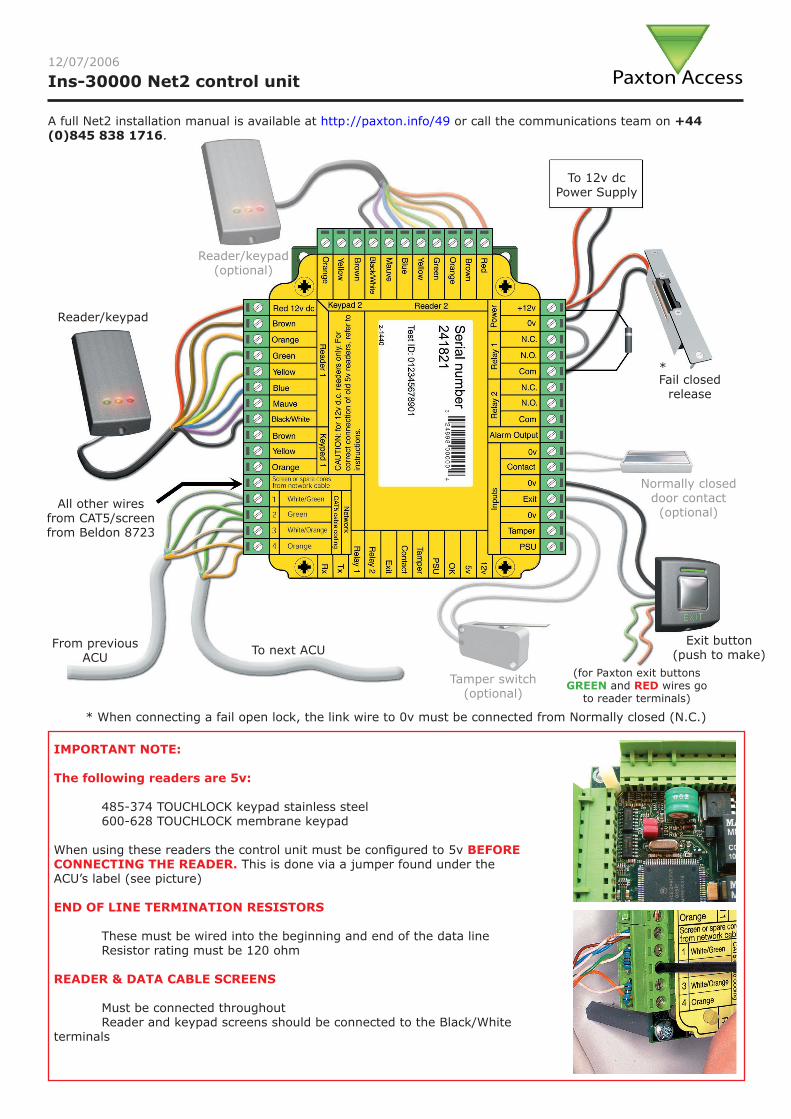
Ins-30000 Net2 control unit
Exit button(push to make)
Fail closed release
Reader/keypad
To 12v dc Power Supply
All other wires from CAT5/screen from Beldon 8723
To next ACUFrom previous ACU
(for Paxton exit buttons GREEN and RED wires go
to reader terminals)
Reader/keypad(optional)
Tamper switch(optional)
Normally closed door contact(optional)
IMPORTANT NOTE:
The following readers are 5v:
485-374 TOUCHLOCK keypad stainless steel 600-628 TOUCHLOCK membrane keypad
When using these readers the control unit must be configured to 5v BEFORE CONNECTING THE READER. This is done via a jumper found under the ACU’s label (see picture)
END OF LINE TERMINATION RESISTORS
These must be wired into the beginning and end of the data line Resistor rating must be 120 ohm
READER & DATA CABLE SCREENS
Must be connected throughout Reader and keypad screens should be connected to the Black/White terminals
* When connecting a fail open lock, the link wire to 0v must be connected from Normally closed (N.C.)
Paxton Access12/07/2006
A full Net2 installation manual is available at http://paxton.info/49 or call the communications team on +44 (0)845 838 1716.
*
Control unit installation
Wire the components to the Access Control Unit (ACU) as shown on the previous page. This will include:
- Reader/Keypad - Electric Lock - Power supply - Any other optional components
Test the ACU is functioning properly:
- Present a token to reader (the reader will beep - no action will be taken as the software has not been set up, however when using PROXIMITY P series and PROXIMITY KP series, the readers will auto configure when the software is installed) - Press exit button or short the terminals in the absence of an exit button to test the relay
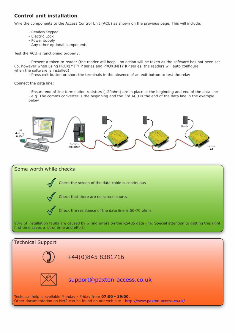
Connect the data line:
- Ensure end of line termination resistors (120ohm) are in place at the beginning and end of the data line - e.g. The comms converter is the beginning and the 3rd ACU is the end of the data line in the example below
Some worth while checks
90% of installation faults are caused by wiring errors on the RS485 data line. Special attention to getting this right first time saves a lot of time and effort.
Check the screen of the data cable is continuous
Check that there are no screen shorts
Check the resistance of the data line is 50-70 ohms
Technical Support
Technical help is available Monday - Friday from 07:00 - 19:00.Other documentation on Net2 can be found on our web site - http://www.paxton-access.co.uk/
+44(0)845 8381716
Software installationOnce all the ACU’s have been tested and the data line connected the Net2 software must be installed:
• Install the Net2 software
Net2 software configures the system to use a Net2 RS232/485 comms converter by default. If a Net2 TCP/IP Ethernet interface is used - see application note AN1006 http://paxton.info/105 If a Net2 modem is used - see application note AN1007 http://paxton.info/106
• Run the Net2 software and detect ACU’s in the Doors screen
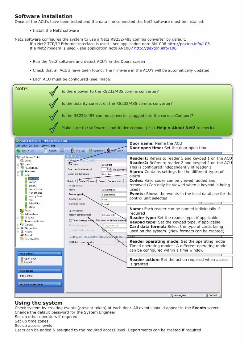
• Check that all ACU’s have been found. The firmware in the ACU’s will be automatically updated • Each ACU must be configured (see image)
Note:Is there power to the RS232/485 comms converter?
Is the polarity correct on the RS232/485 comms converter?
Is the RS232/485 comms converter plugged into the correct Comport?
Make sure the software is not in demo mode (click Help » About Net2 to check).
Using the systemCheck system by creating events (present token) at each door. All events should appear in the Events screenChange the default password for the System EngineerSet up other operators if requiredSet up time zonesSet up access levelsUsers can be added & assigned to the required access level. Departments can be created if required
Reader1: Refers to reader 1 and keypad 1 on the ACUReader2: Refers to reader 2 and keypad 2 on the ACUThis is configured independently of reader 1Alarm: Contains settings for the different types of alarmCodes: Valid codes can be viewed, added and removed (Can only be viewed when a keypad is being used)Events: Shows the events in the local database for the control unit selected
Door name: Name the ACUDoor open time: Set the door open time
Name: Each reader can be named individually if requiredReader type: Set the reader type, if applicableKeypad type: Set the keypad type, if applicableCard data format: Select the type of cards being used on the system. (New formats can be created)
Reader operating mode: Set the operating modeTimed operating modes: A different operating mode can be configured within a time window
Reader action: Set the action required when access is granted

Specifications
Access control unit - in use
Number of doors 1 max
Number of readers 2 max per port
Number of keypads 2 max per port
Number of ACU’s per dataline 200 max
CARDLOCK and PROXIMITY reader cable length 100 max m
Data retention during power cut 7 typ days
Number of events stored on ACU 3,000 max
Number of access levels 250 max
Number of time zones 64 max
Number of individual times in time zones 2,000 max
Door open time 5,000 max s
Number of keypad codes 50 max
Number of cards 10,000 max
Dimensions
ACU only - Board size 102 w 116 h 30 d mm
Recommended space for ACU board in enclosure 170 w 170 h 40 d mm
ACU in 2A power supply - cabinet external dimensions 350 w 330 h 105 d mm
ACU in plastic housing - external dimensions 175 w 170 h 40 d mm
Electrical
Net2 ACU voltage required 11 min 12 typ 15 max V DC
Net2 ACU power consumption at 12V 350 max mA
Net2 ACU relay contact current rating 5 max A
Net2 ACU relay contact isolation 50 min V DC
2A cabinet PSU - output voltage @ 230V a.c. in 13 min 13.8 typ 14 max V DC
2A cabinet PSU - output current 2 max A
2A cabinet PSU - mains supply voltage 210 min 230 typ 253 max V AC
2A cabinet PSU - mains supply current 250 max mA
1A 12 V plastic PSU - output voltage 11.4 min 12.0 typ 12.6 max V DC
1A 12 V plastic PSU - output current 1.1 max A
1A 12 V plastic PSU - mains supply voltage 100 min 240 max V AC
1A 12 V plastic PSU - mains supply current 200 max mA
Number of relay outputs 2
Analogue/digital inputs 4
Alarm outputs 1
Alarm output current 1 A
Product specific information
Width 102 mm
Height 116 mm
Depth 30 mm