instructions manual 16n201305 - cryogenic storage · the sterilizer described in this manual is...
TRANSCRIPT

Operations Manual
PH: 908-769-5555 EM: [email protected]
WEB: www.BenchmarkScientific.com
For Research Use Only

Thank you for choosing the BioClave Benchtop Sterilizer.
Prior to operating this instrument, please read the operations manualcarefully and follow all installation instructions.
TABLE OF CONTENTS
Instructions manual Instructions manual
1.GENERAL ------------------------------------------------------- 1
2.TECHNICAL SPECIFICATIONS --------------------------------- 2
3.PACKING CONTENT ------------------------------------------ 3
4.INSTALLATION ----------------------------------------------- 4
5.OPERATION ----------------------------------------------------- 5
5.1 SETUP -------------------------------------------------------- 5
5.2 PREPARATION OF STERILIZATION MATERIALS ----- 6
5.3 SELECTING THE STERILIZATION PROGRAM --------- 7
5.4 RUNNING THE STERILIZATION PROGRAM ------------ 8
6. ADVANCED SETTINGS --------------------------------------- 11
7. MAINTENANCE ----------------------------------------------- 15
8. TRANSPORT AND STORAGE ------------------------------- 18
9. ERROR CODES ------------------------------------------------ 19
10. SAFETY DEVICES ------------------------------------------- 20
1.WATER PROPERTIES/CHARACTERISTICS ---------- 21
2. DIAGRAMS OF THE STERILIZATION PROGRAMS ----- 22
3.WIRING DIAGRAMS ---- - - - - - - - - - - - - - - - - - - - - - - - - - - - - - - - 25
4. HYDRAULIC DRAWING --------------------------------------- 26
APPENDIX

The sterilizer described in this manual is intended for the sterilization
of research tools. It operates automatically with 134°C and 121°C
sterilization temperatures. This sterilizer is in compliance with the
European Directive 93/42/CEE and it has been produced in accordance
with the EN 13060. In addition the chamber has been ASME certified.
1 General
4
3
2
1
1 Distilled water tank2 LED screen3 Control panel4 Main Power switch5 Drain connector of distilled water tank6 Door handle7 Drain connector of used water tank8 USB port (optional)
9 Printer port10 Printer power11 Bacteriological filter12 Safety valve13 Condenser ventilation14 Circuit breaker15 Power supply cord16 Rating plate
Security NoticeFor safe operation, please pay close attention to the alert symbolsbelow which cab be found throughout this manual. Pleasecarefully read and understand the contents of this manual prior tooperating this instrument.
This symbol represents an electrical caution - ground protection
HOT SURFACE.This symbol represents a warning of a potential hot surface.
Important safety information.This symbol represents a warning for extra caution
567
11
13
15
12
16
8
9
10
1
14
2 Technical Specifications
Chamber
Rated Voltage
Main Fuses
Sterilization Temperature
Capacity of the distilled
water tank
Operation temperature
Exterior Dimensions
Noise Level
Relative Humidity
Atmospheric pressure
Item 16
Φ230mmX360mm
110V-130V or 220V-240V, AC, 50-60Hz
F25A/250V for 110V
121°C/134°C (250°F/274°F)
Approx 2.5L (water at level MAX)
Approx 0.5L (water at level MIN)
5 - 40℃
445mm(width)X 410mm(height)X 605mm(depth)
76kPa -106kPa
max. 80%, non condensing
<70dB
45kg
2
Nominal power 1900VA
Weight99 lbs
Instructions manual Instructions manual

3 Packing Content
QuantityItemNo.
2
3
4
5
6
7
Instrument tray
Instrument tray rack
Instrument tray handle
Door adjustment tool
Draining hose
Instructions manual
2
1
1
1
2
1
1
1 Steam sterilizer 1
3
Door seal8
4 Installation
4Instructions manual Instructions manual
605
Ensure that the sterilizer is installed with 2.5in. (10cm)ventilation space on all sides of the sterilizer, and 5 in. (20cm)on top side. The clearance required to open the door is 15.5in.(40cm).
The sterilizer should be placed on a level worktable.
Do not cover or block the door, ventilation or radiationopenings on the sterilizer.
Do not install the sterilizer near a sink or in a location where itis likely tobe splashed.
Do not install the sterilizer nearby a heat source.

Distilled water tank is requires water.
Distilled water tank is full
Used water tank is full.
Door locked
information output to USB port
Printer is connected
Notice: Before using the sterilizer or at any time the low water
icon blinks, it is necessary to fill the distilled water
tank with distilled water.
5.1 Setup
5.1.1 Open the door and remove all of the inner contents for unpacking.
5.1.2 Connect the power cord to an outlet of the appropriate voltage
5.1.3 Power on
The switch is located underneath the control panel
on the front side of the machine .
After switching on, the machine turns on the LCD
and shows the door position, water level,
working program, date, time and etc.
5 Operation
Program
Alarm code
process curve
Temperature
Pressure
Setting
Time
Date
5
5.1.4 Filling the distilled water
Remove the cover, and fill the tank with distilled water.
When you hear a beep signal, it means the water level exceeds the
max. level. The will be displayed. Please stop filling immediately.
5.2 Preparation of sterilization materials
For the most effective sterilization and to preserve the sample, please
follow below:
* Arrange the samples of different material on different trays or with at least
2in. of space between them.
* Always insert a sterilization paper or cloth between the tray and sample,
to avoid direct contact between the different materials.
6
The water level should notexceeded this port.
Instructions manual Instructions manual
F
F
F

5.3 Selecting the sterilization program5.3.1 LCD
The panel displays the cycletemperature, pressure, error code,sterilization state and program.
5.3.2 Temperature buttonPress this button to togglebetween 121°C and 134°C
5.3.3 Program buttonPress this button to toggle betweenavailable sterilization cycles (see below)
5.3.4 START/STOP buttonPress this button to start the sterilization cycle. To stop a cycle, pressand hold this button for 3 seconds.
Notice: Button will be “locked” for the initial 10 seconds after powerup for system initialization.
7 8
5.4 Running the sterilization program.
After selecting program, the materials
to be sterilized can now be placed on the
tray and the tray placed inside the
chamber using the tray handle
5.4.1 After the instruments are loaded, you
may close and lock the door by turning
the door handle clockwise until it stops.
The icon will be lightened.
Caution You must turn the door handle to the maximum position,:
otherwise the machine will alarm and prevent
completing the cycle.
Instructions manual Instructions manual
UNWRAPPED
WRAPPED
EXTENSIVE
LIQUID
DRYING
274 F
F

Caution: When you press the START button but the door has not been
fully closed. You will see the blinking on the screen.
A cycle can not be started until you close the door to the max.
position and press the "Start" button again.
9
5.4.2 Start the sterilization program.
Press START button, the machine will begin the cycle automatically.
It will take 30-75 minutes. (See Appendix 2)
total time orcount down untilcompletion
After a cycle is completed, the printer will be activated and print out areport of the cycle settings (if the optional printer has been connected).After the pressure returns to 0, the door is unlocked and the materialscan be removed.
5.4.3 Sterilization cycle completion
Always use the tray handle to load or unload the tray into theautoclave. Failure to do so can result in burning.
10
If you need to interrupt a cycle and remove materials urgently.you may hold the START button for 3 seconds after completingsterilization time to skip the dry cycle.This will result in the program skipping directly to the last stepand eliminate the drying stage. After one minute the cyclewill end.
Instructions manual Instructions manual
F
F

6 Advanced Setting6.1 Enter the setting6.1.1 Power on the machine while Holding the
START button and hold for 5seconds. Thiwwill enter into the advanced settings mode.
6.1.2 Select the state (State 1 thru. 3) by pressingthe Program button. Press the STARTbutton to enter the setting.
6.2 S1 stateIf you select the S1. You may changethe unit of temperature and pressure,and adjust time and date.
6.2.1 The first option is to select the unit oftemperature. Press temperature button
to select or℃ .
The unit you selected will be lighted. Pressthe program button to the next item.
6.2.2 You may select the unit of pressure in the same manner.6.2.3 Then press program button to the next item to adjust the time and
date. After the last word of the date or time is set , then the data ispermitted to be saved. If you want to finish the setting you shall pressSTART. It will return to the screen of selecting states.
The Machine No. And cycle No can not be set by the operator.
6.3 S2 state6.3.1 You may check the count of sterilization
cycle. It can not be changed by operator.6.3.2 Set the parameter for high altitude.
If you have trouble completing a cycle in alocation of high altitude (above 2.0 km oratmospheric pressure is below 80kPa)you may need to adjust this parameter.
6.3.3 Language set:00 English 01 German 02 Spanish03 Polish 04 French 05 Magyar06 Romanian 07 Dutch 08 Lithuanian 09 Latvian
cycle No
machine No
Altitude set
Languageset
1211 Instructions manual Instructions manual
F
6.5 Printer (Optional)
6.5.1 Connect the printer cable.
6.5.2 Connect the printer power.
holding time
drying time
Notice: the default sterilization parameters have been chosen to
provide optimal sterilization results. We do not suggest adjusting
these parameters unless it is necessary.
6.4 S3 state
6.4.1 Adjust the length of sterilization and drying time.
Press program button to select the program.( )
Press temperature button to select the temperature of program.
Then press START to adjust the drying time and holding time.
6.4.2 First to adjust the holding time.
Press temperature button to adjust the data.
Press the program button to select
the items.
6.4.3 Press START to save .
6.4.4 Drying time is 0-19.
Holding time of 250 is 1-59.
Holding time of 274 is 1-19.
F
F
274 F
13
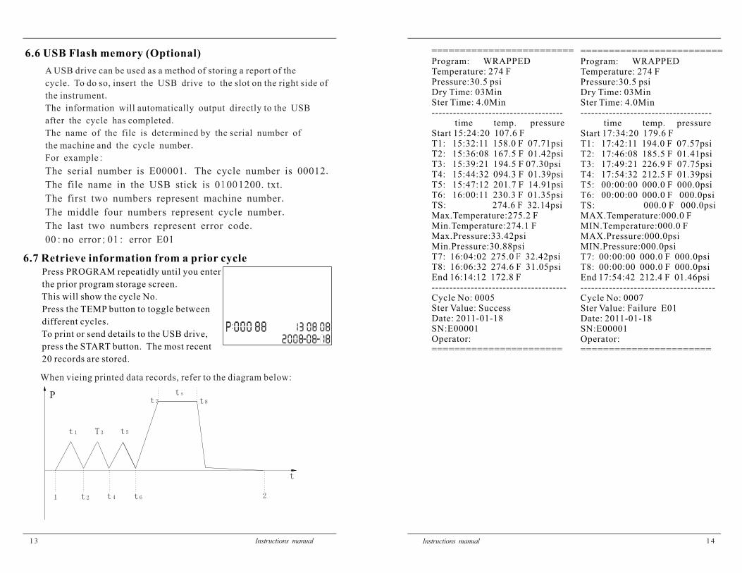
6.7 Retrieve information from a prior cycle
Press PROGRAM repeatidly until you enter
the prior program storage screen.
This will show the cycle No.
Press the TEMP button to toggle between
different cycles.
To print or send details to the USB drive,
press the START button. The most recent
20 records are stored.
When vieing printed data records, refer to the diagram below:
14Instructions manual Instructions manual
A USB drive can be used as a method of storing a report of the
cycle. To do so, insert the USB drive to the slot on the right side of
the instrument.
The information will automatically output directly to the USB
after the cycle has completed.
The name of the file is determined by the serial number of
the machine and the cycle number.
:For example
The serial number is E00001 The cycle number is 00012. .
1 0 . .The file name in the USB stick is 0 0 1200 txt
.The first two numbers represent machine number
.The middle four numbers represent cycle number
.The last two numbers represent error code
: ; :00 no error 01 error E01
6.6 USB Flash memory (Optional)
1 2
t1 T3 t5
t8
t2 t4
t7
tsP
t
t6
=========================Program: WRAPPEDTemperature: 274 FPressure:30.5 psiDry Time: 03MinSter Time: 4.0Min-------------------------------------
time temp. pressureStart 15:24:20 107.6 FT1: 15:32:11 158.0 F 07.71psiT2: 15:36:08 167.5 F 01.42psiT3: 15:39:21 194.5 F 07.30psiT4: 15:44:32 094.3 F 01.39psiT5: 15:47:12 201.7 F 14.91psiT6: 16:00:11 230.3 F 01.35psiTS: 274.6 F 32.14psiMax.Temperature:275.2 FMin.Temperature:274.1 FMax.Pressure:33.42psiMin.Pressure:30.88psiT7: 16:04:02 275.0 32.42psiFT8: 16:06:32 274.6 F 31.05psiEnd 16:14:12 172.8 F--------------------------------------Cycle No: 0005Ster Value: SuccessDate: 2011-01-18SN:E00001Operator:=======================
=========================Program: WRAPPEDTemperature: 274 FPressure:30.5 psiDry Time: 03MinSter Time: 4.0Min-------------------------------------
time temp. pressureStart 17:34:20 179.6 FT1: 17:42:11 194.0 F 07.57psiT2: 17:46:08 185.5 F 01.41psiT3: 17:49:21 226.9 F 07.75psiT4: 17:54:32 212.5 F 01.39psiT5: 00:00:00 000.0 F 000.0psiT6: 00:00:00 000.0 F 000.0psiTS: 000.0 F 000.0psiMAX.Temperature:000.0 FMIN.Temperature:000.0 FMAX.Pressure:000.0psiMIN.Pressure:000.0psiT7: 00:00:00 000.0 F 000.0psiT8: 00:00:00 000.0 F 000.0psiEnd 17:54:42 212.4 F 01.46psi--------------------------------------Cycle No: 0007Ster Value: Failure E01Date: 2011-01-18SN:E00001Operator:=======================

15 16Instructions manual Instructions manual
Clean the external surface
Maintenance Operation
Clean the door seal
Clean the distilled water tank
Clean the sterilization chamber
Replace the door seal
7.1 Clean the distilled water tank everyweek with isopropyl alcohol or amedical disinfectant.
7.2 Clean the chamber weekly.
7.2.1 Remove all trays and the tray rack
from the chamber.
7.2.2 Clean the chamber with a
smooth cloth saturated with
distilled water.
7.2.3 Apply the same procedure for
the trays and rack.
Frequency
7. Maintenance7 Maintenance
Weekly
Every year
Daily
7.4 Clean the door sealClean the door seal weekly, with a smooth cloth saturated with thedistilled water.
Fig 1Fig 2
Caution: Never adjust the chamber door while the door is closed.
7.5 Door adjustment
On normal circumstance the chamber door does not require adjustments.
However, if the seal fails (resulting in steam leaking from the front of
the chamber), you may use the included tool to tighten the door seal.
7.5.1 Open the door
7.5.2 Insert the spanner tool in the gap beneath the plastic cover; use the spanner
to grip the adjusting nut (Fig 1). Turn the nut counter clockwise as
the figure below (Fig 2). This will tighten the sealing plate.
7.5.3 Turn the nut until the sealing plate is tight. If the door knob is too tight,
you may also turn the nut clockwise to loosen it.

1 7
7.6 Replacement of the door seal
7.6.1 Open the chamber door.
7.6.2 Remove the door seal ring carefully by hand.
7.6.3 Clean the door seal ring carefully with a smooth cloth
saturated with distilled water.
7.6.4 Moisten the new seal with medical disinfectant or
isopropyl alcohol.
7.6.5 Insert the new seal and press in sequence as follows:
Caution: Please ensure the chamber and the door have cooledprior to replacing the seal ring.
1). Press in the top and bottomof the seal ring.
2). Press in the left and right sidesof the seal ring.
3). Press the remaining sectionsof the seal ring.
4). Press all areas of the sealsurface for a smooth finish.
1 8
8 Transportation and Storage
8.1 Switch off the sterilizer before transportation or storage. Pull out the
plug to let the machine cool down.
8.2 Drain the distilled water tank and the used water tank
8.3 Conditions for transportation and storage:
Temperature: -20 ~ +55
Relative humidity: 85%≥
Atmospheric pressure: 50kPa~106kPa
7.7 The drain valve
1.Press the included hose on to thedrain valve firmly.
2.Set the drain valve to the openposition by turning it counterclockwise.
3.Pull the drain valve outward, thetank will begin to drain.
4.After finish draining the tank, pushthe drain valve inward and turnclockwise into the closed position .
Instructions manual Instructions manual

1 9
9 Error codes
Code
E1
E2
E3
E4
E5
E6
Description Proposed solution
Steam generator temperaturesensor error
Temperature sensor of chamberwall error
Inner temperature sensor error
Fail to rise temperature
Fail to release the pressure
Door has opened during thecycle
Failure to hold temperature
Program manually interrupted
Power off & run a new cycleContact your Supplier if error persists
Power off & run a new cycleContact your Supplier if error persists
Carefully ensure that the chamber wallis heated. If not contact your supplier
Check to ensure that the used watervalve is fully closed.
Power off & run a new cycleContact your Supplier if error persists
Make sure you have turned the door handleto the max. Position or check the door switch
Shut off the power and restart thepower
Ensure the distilled water tank isn't emptyCheck the inner temperature sensorCheck the door for leaking
E20
E9
Failure to preheat the chamberE12
E11Failure to preheat the steamgenerator
Check the steam generator heaterCheck the steam generator protector
Check the chamber heaterCheck chamber protector
20
(1)Main fuses
Protect the instrument against possible failures of the
heating resistor .
Action: Interruption of the electric power supply.
(2)Thermal cutouts on the main transformer windings
Protection against possible short circuit and main transformer primary
winding overheating .
Action: Temporary interruption of the winding.
(3)Safety valve
Protection against possible sterilization chamber over-pressure .
Action: release of the steam and restoration of the safely pressure.
(4)Safety micro-switch for the door status
Comparison for the correct closing position of the door .
Action: signal of wrong position of the door.
(5)Door safety lock
Protection against accidental opening of the door.
Action: Impediment of the accidental opening of the door during the program.
(6)Self-leveling hydraulic system
Hydraulic system for the natural pressure levelling in case of manual cycle
interruption, Alarm or black-out .
Action: automatic restoration of the atmospheric pressure inside chamber.
10 Safety devices
Instructions manual Instructions manual
21
APPENDIX 1Water Properties/Characteristics
DESCRIPTION FEED WATER CONDENSATE
Evaporate residue
Silicium oxide sio2
Iron
Cadmium
Lead
Rest of heavy metals, excludingiron, cadmium, lead
Chloride
≥10 mg/l
≥1 mg/l
≥0.2 mg/l
≥0.005 mg/l
≥0.05 mg/l
≥0.1 mg/l
≥2 mg/l
≥1.0 mg/kg
≥0.1 mg/kg
≥0.1 mg/kg
≥0.05 mg/kg
≥0.1 mg/kg
≥0.1 mg/kg
≥0.1 mg/l
Phosphates
Conductivity (at 20 )℃
pH value
Appearance
Hardness ≥0.02 mmol/l
Colorless, clean,without sediments
5 7 5- .
≥ μ15 s/cm
≥0.5 mg/l ≥0.1 mg/l
≥ μ3 s/cm
5 7-
≥0.02 mmol/l
Colorless, clean,without sediments
22
DIAGRAMS OF THE STERILIZATION PROGRAMS
APPENDIX 2
Instructions manual Instructions manual
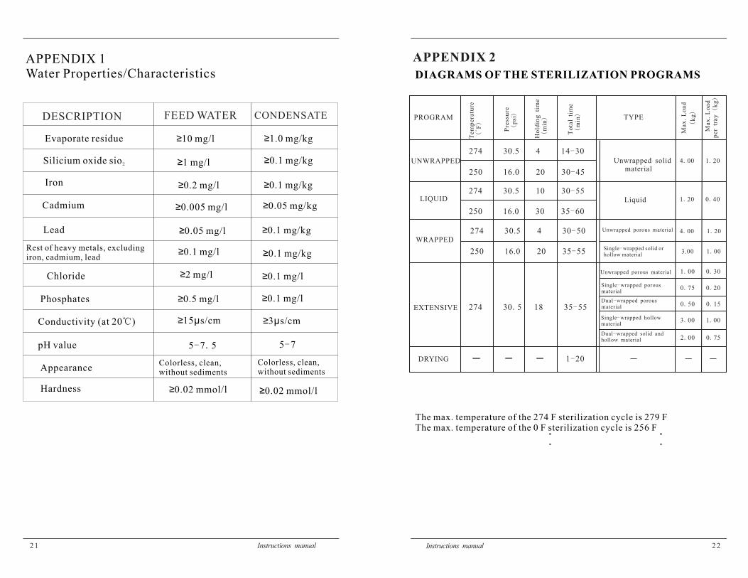
The max. temperature of the 274 F sterilization cycle is 279 FThe max. temperature of the 0 F sterilization cycle is 256 F
PROGRAM
UNWRAPPED
LIQUID
EXTENSIVE
DRYING
Tem
pera
ture
()
F
274 30.5 4 14 30-
274 30 5 18 35 55. -
274 30.5 10 30 55-
250 30 35 60-16.0
250 16.0 20 30 45-
。 Pre
ssu
re(
)p
si
Ho
ldin
gti
me
()
min
To
tal
tim
e(
)m
in
1 20-
Unwrapped porous material
Single wrapped porous-material
Single wrapped hollow-material
Dual wrapped porous-material
Dual wrapped solid and-hollow material
Unwrapped solidmaterial
TYPE
Liquid
3 00 1 00. .
2 00 0 75. .
1 00 0 30. .
0 75 0 20. .
0 50 0 15. .
Max
Lo
ad
.
4 00 1 20. .
1 20 0 40. .
()
kg
Max
Lo
ad
.p
er
tray
kg
()
274 30.5 4 30 50-
250 20 35 55-16.0
WRAPPED
Unwrapped porous material
Single wrapped solid or-hollow material
4 00 1 20. .
3.00 1 00.

2 3
- .0 8 - .0 8
- .0 8 - .0 8
0 0. 0 0.
0 0. 0 0.
1 0. 1 0.
1 0. 1 0.
2 0. 2 0.
2 0. 2 0.
UNWRAPPEDPressure(bar) Pressure(bar)
Pressure(bar) Pressure(bar)
Time(min) Time(min)
Time(min) Time(min)
2 4
WRAPPEDDRYINGEXTENSIVE
DRYING
LIQUID
Instructions manual Instructions manual

2 5
WIRING DIAGRAM
TANK MAX. LEVEL
PRESSURE SENSOR
V4
V1
PRINTERPOWER
KEYBOARDDATA LINE
DOOR CLOSE
Tp1
Tp2
Tp3
~230V(120V)
VACUUMPUMP
~ 9V(2.5A)
~ 9V(0.2A)
~21.5V
~ 0V
FAN
WATERPUMP
STEAMHEATER
THERMALPROTECTOR
CHAMBERHEATER
THERMALPROTECTOR
PUBLIC
TANK MIN. LEVEL
PRINTEROUTPUT
USB DATAOUTPUT
USED WATER TANK
2 6
TP1: Steam generator temperature sensorTP2: Inner temperature sensorTP3: Temperature sensor of chamber wallV1: Air release valveV4: Water release valve
230V(120)
-
+
Instructions manual Instructions manual
APPENDIX 4
HYDRAULIC DRAWING
V1: Air release valve
V4: Water release valve
Chamber
Pressuresensor
Safety valve
Pump
Condenser
Used water tank
Distilled water tank
APPENDIX 3