instructions for model 970-c vacuum pan · pdf fileziegler and associates instructions for...
TRANSCRIPT

Ziegler and Associates
www.zieglerassociates.com
INSTRUCTIONS FOR MODEL 970-C
VACUUM PAN CONSISTENCY MONITOR & PROBE WITH 130V MOTOR

2
FOR PARTS AND INFORMATION CONTACT:
SECO CONTROL SYSTEMS 450 West Larch Road, Suite 5
Tracy, CA 95304 U. S. AMERICA
TELEPHONE 888-798-8300(USA) or 209-839-8600 FAX 209-839-8601
www.zieglerassociates.com Instruction Manual for Model 970-C DATE: 6/24/2008
3
TABLE OF CONTENTS NOTE: This manual is for use with Model 970-C Sugar Consistency Monitor & Probe with 130V motor (serial #1019 and lower). For higher serial numbers using the 24V motor, please visit www.zieglerassociates.com to download the appropriate manual.
DESCRIPTION ................................................................................... 6
CONSTRUCTION ............................................................................... 6
INSTALLATION .................................................................................. 6
Figure 1 - 970-C Probe Dimensions .............................................. 7 Figure 2 - Mounting Dimensions for 970-C Monitor ....................... 7 Figure 3 - 970-C Probe Locations and Head Tank Location ......... 8
WATER PURGE ................................................................................. 8
WIRING .............................................................................................. 9
Figure 4 - Probe to Monitor Wiring for 970-C ............................... 10
START-UP AND CALIBRATION ...................................................... 10
TRANSDUCER CALIBRATION ........................................................ 11
MONITOR CALIBRATION -- OTHER THAN PANS ......................... 11
Figure 5 - Rotor Characteristics for 970-C ................................... 12
WATER LEAKAGE ........................................................................... 13
RECORDER DAMPING ................................................................... 13
BOILING BY CONSISTENCY .......................................................... 13
PAN CIRCULATION ......................................................................... 14
MAINTENANCE - BEARING REPLACEMENT ................................ 15
TROUBLESHOOTING ..................................................................... 16
INFORMATION ................................................................................ 17
MODEL 970-C SUGAR CONSISTENCY MONITOR PARTS LIST .. 17
Circuit Diagram for 970-C ................................................................. 18

4

5

6
DESCRIPTION The Model 970-C Monitor is designed primarily to measure the consistency of syrups and massecuites boiling in sugar vacuum pans. It can be used for other fluids and slurries where viscosity is a good measure of solution concentration or where the viscosity is of prime importance to product quality. It consists of a propeller type rotor driven by a small DC motor and a power supply housed in the Monitor case with an indicating meter to measure variations in current to the motor armature; it increases with rising viscosity of the fluid in which the propeller is turning. An amplifier converts the meter reading to a standard 4 to 20 mA output signal for actuating standard recorders, controllers or I/P transducers. The meter scale is calibrated 0 to 100% of the desired viscosity range which can be selected by means of the zero and span adjustments on the front of the Monitor case. If set for zero with the rotor running in air and 100% with the rotor stalled, the range is from essentially zero to infinite viscosity and the readout is approximately logarithmic over the middle 80% of the scale. This feature enables the Monitor to give adequate readability over the wide range of consistencies encountered in sugar massecuites with viscosities between about 400 and 20,000 centipoise.
CONSTRUCTION Wetted probe parts are stainless steel and the sleeve bearings are a Teflon-ceramic compound for proper coefficient of thermal expansion. They require water for lubrication and to keep syrup or crystals from entering the bearing surfaces. The monitor case is powder coated steel.
INSTALLATION Monitor and probe dimensions are given in Figure 1 and Figure 2. Normal probe location is in the side of a vacuum pan so the rotor is about midway between the lower tube sheet of the calandria and the pan bottom. Preferred mounting is position A in Figure 3 with a slight downward angle so that the rotor will be in an area of good massecuite circulation although horizontal mounting as at B is satisfactory. On some pans, it may be necessary to install as at C through the pan bottom to get the rotor in a good free area but the mounting angle should not be over 75 degrees from horizontal as there is danger of purge water leaking into the motor bearings. The rotor should be located between syrup feed inlets and away from any obstruction so that it will measure a freely moving sample of average massecuite.

7
Figure 1 - 970-C Probe Dimensions
Figure 2 - Mounting Dimensions for 970-C Monitor
Cut a hole in the pan at the selected location and weld on a 2" NPT coupling. As an alternate, a 2" NPT nipple may be used with a 2" union to allow easy withdrawal of the probe between strikes if it becomes necessary to inspect it or perform maintenance. A plugged half union can be used to close the opening until the probe is reinstalled.

8
Figure 3 - 970-C Probe Locations and Head Tank Location
Install the rotor on the shaft tightening the set screws securely. Screw the probe into the 2" connection using the hex head bushing, not the probe barrel, and tighten until the 1/4" NPT water inlet is at the desired position for easy access. If this is not at the top as normally shipped, loosen the three #8-32 set screws that retain the barrel in the mounting sleeve using the spline head set screw wrench provided and rotate the motor so that the elongated access hole in the sleeve faces directly downward to drain water leaking from the outer bearing. This is most important as water entering the motor can quickly cause serious damage to the windings. Do not switch motor leads on the terminal block as they are set for the correct motor rotation which is clockwise as viewed from the motor end. If clearance is restricted so that the motor mounting plate cannot be turned freely when installing, loosen the three set screws in the mounting sleeve and the two set screws in the motor end of the flexible coupling (through the access hole) and carefully slide the motor assembly off the barrel. The barrel and shaft assembly may then be installed in the pan and the motor assembly replaced in the proper position with the access hole down. Before tightening the three retaining screws, push the flexible coupling onto the motor shaft to full immersion and tighten the two set screws securely being certain that one screw is over the flat on the motor shaft. Then secure the motor and barrel assemblies with the 3 set screws.
WATER PURGE Probes must be continuously supplied with relatively clean water at a pressure higher than the head of the massecuite when the pan is full and vacuum is broken. This will be roughly 10 psig (0.7 Kg/Cm2) for normal pans or more than 1.5 times the height of

9
massecuite above the probe. The water can be supplied to all probes on a pan floor from a suitable reducing valve but the recommended method is to locate a head tank of approximately 50 gallons capacity at a sufficient height above the probes to supply the required head and fit it with a float valve to provide a constant supply of water in spite of possible loss of water for several hours. Centrifugal wash water is generally suitable although clean condensate may be used. Avoid using raw water as it may produce scale on shafts and bearings as it is heated to pan temperature in the probe barrel. De-ionized water may be desirable in extreme cases. In any event, take the tank outlet off above the bottom so that sediment or scale will settle in the tank and not in the probe barrels. The required water flow is so small that several probes can be supplied through 1/4" OD tubing. Water supplies lubrication for the plastic bearings and if the supply fails for any extended period, bearings and shaft will be damaged and may require replacement. A pressure gauge on the probe water supply line is a good precaution if it is routinely checked. If not, a simple pressure switch connected to an alarm to notify of water failure can prevent needless maintenance. If water does fail, turn off power to all probes until it is restored. Bearing life can be prolonged if power to the probe is switched off between strikes. Experience indicates that adequately lubricated and purged bearings will not show excessive wear after one year running time. Replacement can be made easily; spare bearings and mounting parts are furnished. See the section entitled "Bearing Replacement". Syrup leakage into bearings will cause no damage but high meter readings will be noted until the contaminating syrup is gradually washed out by the purge water flow.
WIRING Locate the Monitor at a point convenient for observation by the pan operator. Panel cut-out dimensions are given in Figure 2. Two #6-32 flat head mounting screws are furnished. Suitable stand-offs may be fashioned for face mounting. It should not be located at a place subject to excessive vibration. Remove the front panel (2 screws), pull out the plug on the circuit board and set the panel aside while mounting and wiring. Connect the monitor to the probe with 2 wires, #22 or larger. Belden 8441 cable is very adequate and although the shielding is not necessary it gives added mechanical protection. Wiring diagram is shown in Figure 4. Terminals 1 and 2 of the probe connect to the corresponding terminals of the monitor. Terminal 3 is not used. Before connecting power be sure solder terminals A, B, C & D on the circuit board are jumpered for the proper line voltage as shown in Figure 4. Bring 115/230VAC power to terminals 8 and 9. Maximum load is approximately 70 volt amperes. It is suggested that power leads be brought through the right hand case access hole and the probe and output cables through the left hand inlet.
10
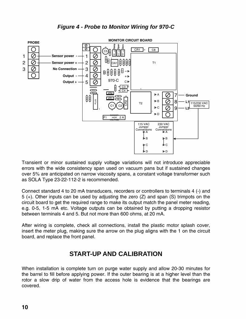
Figure 4 - Probe to Monitor Wiring for 970-C
Transient or minor sustained supply voltage variations will not introduce appreciable errors with the wide consistency span used on vacuum pans but if sustained changes over 5% are anticipated on narrow viscosity spans, a constant voltage transformer such as SOLA Type 23-22-112-2 is recommended. Connect standard 4 to 20 mA transducers, recorders or controllers to terminals 4 (-) and 5 (+). Other inputs can be used by adjusting the zero (Z) and span (S) trimpots on the circuit board to get the required range to make its output match the panel meter reading, e.g. 0-5, 1-5 mA etc. Voltage outputs can be obtained by putting a dropping resistor between terminals 4 and 5. But not more than 600 ohms, at 20 mA. After wiring is complete, check all connections, install the plastic motor splash cover, insert the meter plug, making sure the arrow on the plug aligns with the 1 on the circuit board, and replace the front panel.
START-UP AND CALIBRATION When installation is complete turn on purge water supply and allow 20-30 minutes for the barrel to fill before applying power. If the outer bearing is at a higher level than the rotor a slow drip of water from the access hole is evidence that the bearings are covered.

11
Turn the power switch on and note the meter reading; it should be close to zero on the scale. Touch the flexible coupling through the access hole and note that the reading increases. Stall the probe and the reading should rise to about 100%. Allow the probe to run in the empty pan for 15 minutes or more until the reading stabilizes and, with the zero adjustment, set it at 0%. Stall the probe and set the span adjustment for a reading of 100%. These preliminary settings may be improved later for better readability in the range of most interest. When syrup is drawn into the pan and covers the probe rotor, the indication will jump up to 20 or 25%. As the syrup is concentrated prior to seeding, it will climb to 30 or 35% and, for a time after seeding, will remain constant if the syrup concentration is unchanged. As the massecuite "pulls together", the increasing crystal crop will add to the syrup viscosity and the reading will rise to 40 or 45%. During final brixing to dropping consistency, readings around 80% are to be expected. If more readability is required, zero and span settings can be adjusted so that only the area of interest is covered. This is best done while a typical strike is being boiled. At the lowest viscosity to be measured, adjust the zero screw to get a 0% reading and just before pan drop when the viscosity is highest, set the span screw to read 100%. After final adjustments are reached, the two potentiometer shafts may be locked by tightening their outer hex nuts.
TRANSDUCER CALIBRATION The meter has a range of 0 to 1 volt and an amplifier converts this to the normal 4 to 20 mA input of most transducers, recorders and controllers. For other ranges, two trimpots marked "Z" (zero) and "S" (span) on the circuit board can be adjusted to accommodate others with inputs such as 0-5, 1-5, 0-16 mA etc. Or by connecting a suitable resistor between terminals 4 and 5, voltage outputs are obtained. The easiest way to match meter reading with that of the receiver is to set span and zero pots on the front panel so that the meter is driven from 0 to 100% as the probe rotor is stalled and adjusting Z and S on the circuit board until the two readings agree at the two extremes. A dampening adjustment, marked “damp” on the circuit board, adjusts dampening from 1 to 30 seconds. Turning the adjustment clockwise will increase dampening.
MONITOR CALIBRATION -- OTHER THAN PANS The standard 970-C Monitor can be used as is or modified to provide good readability on syrups or slurries with much lower and narrower viscosity ranges than those normally encountered in pan massecuites. Figure 5 is a plot of typical readings obtained in material of various viscosities; span and zero settings adjusted so that it reads 0 at zero viscosity and 100% at infinite viscosity. With the standard 1-3/4" diameter rotor, the best readability is obtained in the viscosity range 1.5 decades on either side of the 50% point of 1500 centipoise or roughly from 50 to 30,000 cP. By using a rotor of larger diameter, the curve can be centered around lower viscosity fluids. For example, a 3" rotor at narrower span settings can easily cover

12
the viscosity area between 3 and 80 cP, corresponding to syrup concentrations of 50 to 75 brix at normal evaporator outlet temperature of 650C. Due to syrup characteristics, mid-scale readings of 50% will correspond to 65 brix giving excellent readability over the normal range of evaporator operation. The same applies to melters and molasses dilution tanks.
Figure 5 - Rotor Characteristics for 970-C
(Minimum Span is 28%)
On such applications, the easiest calibration method is to set minimum "span" (full clockwise) and adjust "zero" to get a mid-scale reading at the normally desired syrup concentration. For syrup measurement in open tanks such as melters the probe may be put through a 2" NPT coupling and the larger rotor affixed after the probe is in place. For in-line measurement, the probe can be put into a 3" or 4" bushing or flange and the rotor attached before installation in the line. Adjustment note: span adjustment does not affect meter reading at the bottom of the scale, zero milliamps; it only changes the rate of pointer movement above zero. That is why it is suggested that "zero" be first set at the low end of the scale and then "span" be adjusted to obtain the desired high reading at the upper end of the useful consistency range.

13
WATER LEAKAGE If water dripping from the outer shaft bearing onto the pan floor is objectionable, a small funnel or drip pan can be located below the mounting sleeve access hole so that it can be carried away to a floor drain. Under no circumstances should the water flow from the access hole be restricted or there is danger of it overflowing through the motor mounting plate and damaging the motor.
RECORDER DAMPING Massecuite consistency measurement is often rather "noisy" due to erratic circulation patterns in vacuum pans. It is often desirable to damp the measurement rather heavily to produce a more meaningful record. There is a dampening adjustment on the circuit board labeled “damp”. Dampening can be set from 1 to 30 seconds. Clockwise increases dampening. It should be set to a point that slows down the pen/meter movement when random fluctuations occur but not enough to retard the indication of actual consistency trends. It is normal for the indication to move while adjusting the dampening. After adjustment the indication will return back to the correct consistency.
BOILING BY CONSISTENCY By watching the Consistency indication on the 970-C Monitor, it is easy to adjust syrup feed throughout a strike to hold desirable massecuite consistency. If connected through a suitable controller operating a feed valve, the need for manual feed regulation is eliminated. On strikes starting from a footing of crystals it is only necessary to position the control set pointer at the desired consistency and it will be maintained until maximum massecuite level is reached and feed is shut off. During final concentration to dropping brix, the 970-C indication will rise to some optimum final consistency. Strikes started from a syrup charge and seeded require some knowledge of syrup oversaturation (such as that provided by a Model 970-M Oversaturation Monitor) until the massecuite reaches a suitable boiling consistency but feed control from the 970-C can be very helpful even during the early stages of such strikes. Consistency is a good measure of syrup viscosity and hence syrup concentration up until crystal yield rises to 5% to 10% of total solids and then the crystals begin to add to the viscosity of the syrup. From then on, it reads consistency of the massecuite, not the syrup viscosity. During concentration of a graining charge, the consistency reading will increase along with the syrup oversaturation since it is merely measuring the syrup viscosity. When the pan is seeded at the proper oversaturation, the consistency set point may be positioned to admit syrup feed and hold the concentration constant. As crystal area increases, the oversaturation begins to fall and the consistency set point can be raised in small steps

14
to keep the oversaturation near the upper limit of the metastable zone. After a few upward adjustments, the set point will be 10 or 15% higher and the massecuite will have been brought safely to a good boiling consistency and will be held there until the pan is full and feed shut off. With Consistency control, it is a simple matter to prolong a pan feeding cycle. On low grade pans especially, crystals grow slowly and, if feed is heavy, the pan may fill before grain has had tine to develop fully. Rather than dilute syrup feed in the supply tank, it is better to slow the rise in pan level by feeding some water to the pan itself. When a set flow of water is introduced, feed syrup flow will be quickly reduced by the consistency control to maintain its set point and the level rise will be slowed. If, due to an insufficient syrup supply or the need to keep pans in sequence, it is necessary to stop syrup feed entirely, the water flow can be adjusted so that the syrup valve just closes but the consistency will remain constant. It is better to hold a pan on water at normal boiling consistency than to attempt it on heavy massecuite because it is difficult to get adequate mixing of the water feed when pan circulation is slow.
PAN CIRCULATION The 970-C measures consistency in the vicinity of the probe rotor, not necessarily an average of the pan contents unless circulation is very good. On pans equipped with a mechanical circulator, consistency readings will be quite steady and representative of the average value. Even during final brixing, the monitor indication will rise quite smoothly to the dropping point. The circulation pattern may be more erratic on pans without mechanical agitation and this will be most evident on the Monitor indication. If pan circulation almost ceases during final concentration, the Monitor reading should be checked by other observations such as a proof stick sample. Massecuite movement in vacuum pans is very sluggish except in the ebullition zone near the top surface where vapor bubbles form and break; in the calandria area it is almost negligible. Fresh syrup feed introduced near the top of the calandria center well will float to the surface instead of being drawn down to mix with the massecuite; even a mechanical circulator will not prevent this. Feed syrup must be mixed with the slow moving massecuite and the best way to do this is to introduce it at several points below the bottom tube sheet near the outside wall or into the discharge side of the circulator impeller. Hot feed that flashes upon entering assists the overall circulation. Mechanical circulators only increase massecuite movement in the calandria area; they do nothing in the body of the pan to keep crystals in suspension. Without vigorous boiling above the calandria, crystals can settle out. Typical vacuum pans operated with less than 40 to 500C across the heating surface suffer from inadequate circulation. A 970-C probe should never stall in fluid massecuites even at very high viscosity. Most reports of this difficulty are traceable to operation with low steam pressure letting crystals settle and pack around the probe rotor. On a few occasions, contaminated purge water has deposited scale or dirt in the bearings increasing the friction and producing high readings.

15
MAINTENANCE - BEARING REPLACEMENT The 970-C Consistency Monitor is designed for long life but any device with moving parts will eventually require maintenance. Excessive wear of probe shaft bearings will be indicated by increased water leakage from the outer bearing. Initially water flow will be only a few ml/min. but when it approaches 200 ml/min. the bearings should be replaced with the spare set furnished. Bearing replacement is quite simple but it is best to perform the operation in the instrument shop. 1. Disconnect water supply, remove motor splash cover and disconnect incoming
wires. Remove probe from pan and wash off adhering syrup, protecting motor from splashing.
2. Loosen the two spline head set screws in the motor end of the flexible coupling
and back off the three screws in the motor mount sleeve. Carefully pull barrel and shaft assembly out of the motor mount.
3. Remove rotor and pull the shaft out from the flexible coupling end. Remove the
three set screws at the rotor end of the barrel and pull out the inner bearing retainer bushing.
4. Inspect shaft and inside of the barrel for possible scale or dirt accumulation and
clean them up. 5. Press old bearings out of their retaining O-rings using finger pressure or a 5/8"
rod if necessary. Inspect the two internal O-rings and the internal one on the inner bearing retainer and replace if necessary with the spares furnished. Grease O-rings lightly with silicone lubricant.
6. Press new bearings into the retainers until the O-rings snap into the bearing
groves. Be very Careful not to get grease on the inside bearing surfaces or it will cause erratic and high readings until it is eventually washed out by the purge water.
7. Inspect shaft for excessive wear or scoring and replace if necessary. Wipe shaft
clean and slide it through the outer bearing. Slip on the inner bearing retainer and press it into the barrel until it seats. Replace the three set screws that hold it in place so that the shaft is seated in the flexible coupling and set screws are tight. Replace rotor.
8. Slide barrel and shaft assembly into motor mount sleeve and tighten the three set
screws with the water purge connection at the required angle. 9. Push flexible coupling fully on to motor shaft seeing that one set screw is over the
flat and tighten the two screws through the access hole.

16
10. Install probe, connect water and wires. Be sure the barrel fills with water before operating. If probe is ever to be operated on the bench, pour barrel full of water and keep probe horizontal so that both bearings are wetted continuously.
11. New bearings and shafts sometimes give a high reading until they have run in for
an hour or so. After the reading stabilizes, recheck zero and span adjustments as previously described.
TROUBLESHOOTING If motor fails to run, see if shaft and rotor are free by turning with a finger through the access hole. Check to see that 120 VAC is reaching the AC terminals of the rectifier on the circuit board. If not check continuity of the 2 ampere fuse and the on-off switch on the front panel. The DC output of the rectifier appears on wiring terminals 1 (-) and 3 (+) and should be approximately 130 VDC. Changes in armature current with rotor load actuate the indicating meter and supply the 4-20 mA. output signal. With the motor running free the armature current is at a minimum. The voltage drop across the 300 ohm armature resistor is a good measure of this current. Voltage can be measured between terminals 3 (+) and 2 (-). With the motor running free this voltage should be about 15 volts. With the motor at stall the voltage should be about 90 volts. Armature current (terminal 2) changes from about 50 to 300 mA as load is applied. The motor should never stall completely in normal operation even in very heavy massecuite but if it does, it could indicate worn motor brushes or a dirty commutator segment. Check brushes and replace if badly worn. Remove back end bell of motor and inspect the commutator, cleaning with fine sandpaper if needed. To be sure that external friction is not the cause, disconnect the probe shaft at the probe end of the flexible coupling and check for dirty or scaled bearings or compaction of sugar crystals around the rotor. The Bodine motors have special brushes which should be ordered from Ziegler and Associates. In ordering replacement brushes, specify the motor manufacturer and brush dimensions. The circuit board is protected by a 2 ampere fuse. If the fuse blows check the wiring between the monitor and the probe as it is a sign that terminals 1 and 2 have been shorted. Maximum motor current at stall is only 0.3 ampere when properly connected. Do not over-fuse as circuit board damage can result.

17
INFORMATION For additional information regarding installation, parts, or service please contact Ziegler and Associates at the address in the front of this manual.
Ziegler and Associates
MODEL 970-C SUGAR CONSISTENCY MONITOR PARTS LIST
PART# ITEM DESCRIPTION970C001 Transmitter Transmitter970C002 Sensor Sensor/probe unit970C003 Circuit Board Circuit board970C004 Front Panel Assembly Front Panel Assembly970C005 ZA-6 Kit ZA-6 Kit for 715TQ conversion970C007 Motor 24A2BEPM Motor (Bodine type 24A2BEPM) 970C008 Shaft Sensor/probe shaft970C009 Barrel Sensor/probe shaft barrel970C010 Motor Mount Sensor/probe motor mount 970C011 Motor Spacers Sensor/probe motor spacers (set of 4) 970C012 Bearing Sensor/probe bearing970C013 Terminal Block Sensor/probe terminal block 970C014 Flex Coupling Sensor/probe flex coupling with set screws 970C015 Rotor 1-3/4" Sensor/probe rotor 1-3/4"970C016 Rotor 3" Sensor/probe rotor 3"970C017 Motor Bearing (Bodine - Z99038) Motor ball bearing (Bodine - Z99038) 970C018 Motor Bearings (Carter - C8008) Motor ball bearing (Carter - C8008) 970C019 Motor Brush (Carter) Motor brush with spring for Carter motor 970C020 Motor Brush (Bodine F83) Motor brush with spring for Bodine motor (1/4" x 1/8")(F 83)970C021 Motor Brush (Bodine F83X) Motor brush with spring for Bodine motor (1/4" x 3/16")(F 83X)970C022 O-Ring #114 O-Ring Bearing Retainer #114 - 5/8 x 13/16" 970C023 O-Ring #217 O-Ring Barrel Seal #217 - 1 3/16 x 1 7/16" 970C024 Set Screw Set Screw - 8-32 x 3/16" Spline Head SS 970C025 Meter (Analog) Analog indicating meter with dial for front panel 970C026 Meter (Digital) Digital indicating meter for front panel 970C027 Potentiometer 10k ohm potentiometer for front panel 970C028 Splash Hood Sensor/probe motor splash hood 970C029 Bearing Retainer Sensor/probe inner bearing retainer 970C030 Wrench Spline head wrench970C031 Screws Screws and washers for splash hood (2 of each included)
18
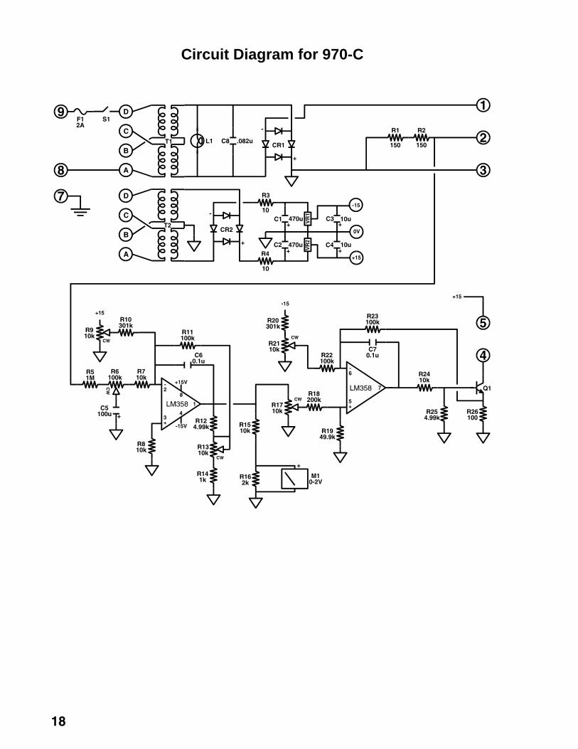
Circuit Diagram for 970-C


