instructions for installation of polysolar ps-a, ps-c ... guide polysolar .pdf · 2.1.6 beware of...
TRANSCRIPT
PS Series module Instructions for Installation Date: 24/08/12
Polysolar Limited. 2012 All rights reserved
1
Instructions for Installation of Polysolar PS-A,
PS-C series PV modules
Polysolar Limited Hauser Forum, Charles Babbage Road, Cambridge, CB3 0GT, UK
TEL:+44 (0)1223 911534
Email : [email protected] WEB:www.polysolar.co.uk
PS Series module Instructions for Installation Date: 24/08/12
Polysolar Limited. 2012 All rights reserved
2
1. Introduction This instruction is provided for you to install and operate Polysolar Limited PV modules. Before the
installation or operation, please read the general information and safety guidelines carefully. If any
questions about installation and operation remain, please contact Polysolar or its sales agent. You
should be aware that the warranty may be invalidated as a result of improper installation and
operation.
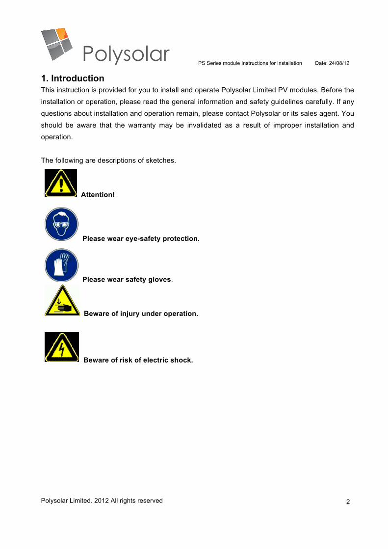
The following are descriptions of sketches.
Attention!
Please wear eye-safety protection.
Please wear safety gloves.
Beware of injury under operation.
Beware of risk of electric shock.
PS Series module Instructions for Installation Date: 24/08/12
Polysolar Limited. 2012 All rights reserved
3
2. General instructions This photovoltaic module produces electricity when exposed to the sun or other light source. For
users and installers’ safety, please read the entire instructions carefully prior to installation and PV
system operation. Also, carefully read the PV module data sheet provided with this product to
understand the physical and electrical properties. Determine local permits, installation and
inspection requirements before installing PV module(s). Polysolar Ltd assumes no liability for
damages incurred due to non-compliance with these instructions. Please also read the instructions
for the other components which make up the whole PV system.
2.1 Special instructions
2.1.1 Do not attempt to disassemble the PV module, and do not remove any attached
nameplates or components! Doing so will void the warranty.
2.1.2 Do not disconnect under load! Doing so may cause electric shock or the system to fail.
2.1.3 Do not use mirrors or other hardware to artificially concentrate sunlight on the PV module!
This will damage the PV module and may be dangerous!
2.1.4 Do not use organic solvents to clean the surface and sides of the PV module.
2.1.5 Handle with care! Impact may break the PV modules and cause malfunction, electric
shock and/or injury.
2.1.6 Beware of the risk of electric shock and short-circuits, as the PV modules generate high
voltage and current when exposed to light.
2.1.7 If PV modules are installed above ground level, wear a safety belt and protection gloves
when installing the PV modules to prevent the risk of falling and of electric shock.
2.1.8 In the UK, modules should be installed according to MIS3002 by MCS certified personnel.
2.1.9 Keep this instruction together with the documentations of the PV module.
2.2 Standard Operating Conditions
2.2.1 The PV modules should be operated under sufficient sunlight; exposure to seawater or
snowfall (1 meter or more) should be avoided.
2.2.2 Ambient temperature should be in the range between -20 °C and 50 °C, and PV module
operating temperature should be in the range between -20 °C and 85 °C.
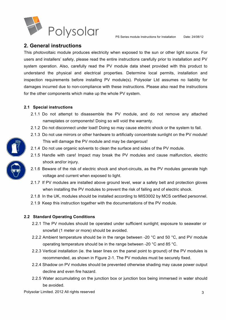
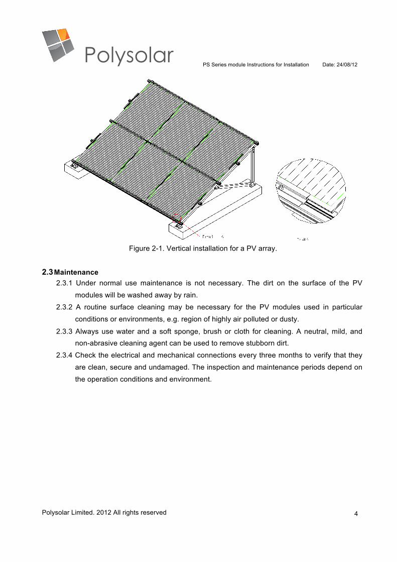
2.2.3 Vertical installation (ie. the laser lines on the panel point to ground) of the PV modules is
recommended, as shown in Figure 2-1. The PV modules must be securely fixed.
2.2.4 Shadow on PV modules should be prevented otherwise shading may cause power output
decline and even fire hazard.
2.2.5 Water accumulating on the junction box or junction box being immersed in water should
be avoided.
PS Series module Instructions for Installation Date: 24/08/12
Polysolar Limited. 2012 All rights reserved
4
Figure 2-1. Vertical installation for a PV array.
2.3 Maintenance 2.3.1 Under normal use maintenance is not necessary. The dirt on the surface of the PV
modules will be washed away by rain.
2.3.2 A routine surface cleaning may be necessary for the PV modules used in particular
conditions or environments, e.g. region of highly air polluted or dusty.
2.3.3 Always use water and a soft sponge, brush or cloth for cleaning. A neutral, mild, and non-abrasive cleaning agent can be used to remove stubborn dirt.
2.3.4 Check the electrical and mechanical connections every three months to verify that they
are clean, secure and undamaged. The inspection and maintenance periods depend on
the operation conditions and environment.
PS Series module Instructions for Installation Date: 24/08/12
Polysolar Limited. 2012 All rights reserved
5
3. Safety instructions
Be familiar with the basic principles of electricity and electrical equipment. Use properly insulated
tools and appropriate protective equipment such as safety shoes, work gloves, and protection
goggles. Use a properly and approved voltmeter for measuring the electrical properties of PV
systems and single PV module.
3.1 To avoid electric shock when working on PV module wiring, covering faces of PV module
completely with opaque materials is recommended to prevent electricity generation. 3.2 Isolate PV module(s) from other sources of electricity, such as batteries or inverters, before
completing whole PV system wiring work. 3.3 Avoid contact terminals when PV modules are exposed to light. 3.4 Do not remove any parts originally installed or disassemble the PV module. 3.5 Exercise utmost caution when working on wiring up to and installing the inverter. 3.6 Do not attempt to install or use a PV module with broken or damaged front glass or back
glass.
3.7 Check PV modules for cracks, damage, or loose wires/connectors/junction boxes. Remove
and do not try to clean or use cracked or damaged PV modules.
3.8 Do not use high pressure water spray or organic reagents to clean the PV modules.
3.9 To avoid risk of electric shock, the operator should wear insulated gloves and shoes to
avoid direct contact with the cleaning solutions or PV modules.
The PV modules are qualified for application class A: Hazardous voltage (IEC 61730: higher
than 50V DC; EN 61730: higher than 120V DC), hazardous power applications (higher than 240W)
where general contact access is anticipated (PV modules qualified for safety through EN IEC
61730-1 and -2 within this application class are considered to meet the requirements for safety
class II).
PS Series module Instructions for Installation Date: 24/08/12
Polysolar Limited. 2012 All rights reserved
6
4. Unpacking, Transportation and Storage
4.1 Unpacking the PV modules and storage: Utmost care is required when handling PV modules. Use care when unpacking, transporting, and storing the PV modules.
4.2 The PV module is frameless double-glass laminated configuration; any collision should be avoided during transport and installation. Any damage at the corners or boards caused by
collision easily lead to future brakeage from these injured sites may be ignited by
temperature, stress, or other factors. If a collision occurs, you must inspect whether
damage caused at the edges or corners, no damage should be confirmed prior to
installation.
4.3 If installed PV modules are broken, immediately replace to avoid risk of leakage and damage to personnel and PV system.
4.3.1 Transport PV modules in an upright position and carry PV modules with both hands.
4.3.2 Do not lift PV modules by grasping the PV module’s junction box, cables or connectors.
4.3.3 Ensure PV modules are installed/stored without self-weight deflections. Do not stack PV modules on the top of other PV modules.
4.3.4 Don’t mark using sharp tools and keep all electrical contacts clean and dry.
4.3.5 Avoid non-uniform mechanical load during installation, transportation and storage to prevent the risk of cracking the PV module.
4.3.6 After unpacking, please note the possibility of dirt getting into connectors. 4.4 Figures 4-1. and 4-2. are the unpacking instruction for 30- and 40-module crates,
respectively. A star T-25 screw driver is needed to remove the screws from the crate.
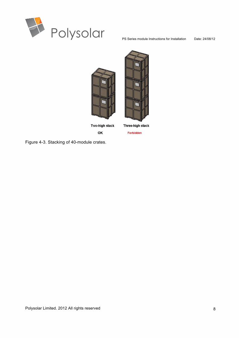
4.5 For 30-module and 40-module crates, stacking more than three-high and two-high, respectively, is forbidden. Stacking models for 40-module crates are shown in Figure 4-3.

PS Series module Instructions for Installation Date: 24/08/12
Polysolar Limited. 2012 All rights reserved
7
Figure 4-1. Unpacking steps for a 30-module crate.
Figure 4-2. Unpacking steps for a 40-module crate.
PS Series module Instructions for Installation Date: 24/08/12
Polysolar Limited. 2012 All rights reserved
8
Figure 4-3. Stacking of 40-module crates.
PS Series module Instructions for Installation Date: 24/08/12
Polysolar Limited. 2012 All rights reserved
9
5. Installation instructions 5.1 Beware that PV modules exposed to a wide range of mechanical conditions may cause surface
stress to appear.
5.2 Beware due to different thermal coefficients of glass and metal clamps/ support structure,
thermal stress may occur as a result of outdoor exposure.
5.3 Refer to MIS3002 (& DIN 1055) for basics for the planning of a structural framework regarding
building structures which must be taken into account.
5.4 Structural strength of PV system must be sufficient, with no deformation caused by static load or
dynamic load. Deformation of the support structure may pull PV modules to distortion, and
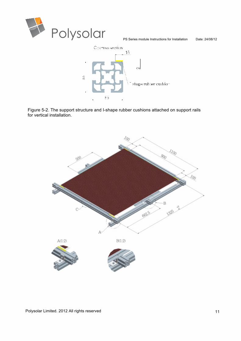
cause the damage of PV modules through to stress. 5.5 Slight sinkage phenomenon resulted from self-weight deformation of the PV module, leads to
not only accumulation of dust or dirt and decreases of power output, but also a poor
appearance which is an important issue for BIPV systems. When installing with a tile angle of
less than 60 degrees, it is strongly recommended that the back-side central area of the PV
module is supported (see Fig. 5-2).
5.6 Mounting procedure:
5.6.1 For reference, clamps/rubber cushions and support structure of PV modules are shown
in Figures 5-1 and 5-2, respectively.
5.6.2 Firstly, complete the mounting support structure, as shown in Figure 5-2.
5.6.3 The PV module, which is fragile double-glass laminated configuration, should not directly
contact metal parts of clamps or support structure. Weather durable isolation materials
and cushions (i.e. L- and I-shape rubber cushions shown in Figure 5-1) with appropriate
thickness and hardness are required to be placed between the support structure and the
PV modules. The suggested materials are either thermoplastic vulcanizates (TPV) or
ethylene propylenediene monomer (EPDM).
5.6.4 Set up the PV modules firstly from the lower edge of support structure with pre-mounted
900mm U-/Z-clamps (without fastening) which can temporarily support the weight of PV
modules during installation. Mount and fasten 500mm U-/Z-clamps at both vertical sides
after PV module is placed onto support structure. Finally lock 900mm U-/Z-clamps on the
upper and lower sides of support structure.
5.6.5 The overlap for PV module and clamps should be controlled between 12 mm and 14 mm.
The clamps insure that the PV modules resist high wind/snow loads, and prevent them
from being rolled up.
5.6.6 PV modules must be fastened linearly along both vertical sides in accordance with the

PS Series module Instructions for Installation Date: 24/08/12
Polysolar Limited. 2012 All rights reserved
10
support structure. A horizontal middle support is placed to prevent non-admissible bending
or deformation of the PV modules.
5.6.7 The PV module can be damaged for over torque and result in cracks at the overstressing
secured areas. For mounting, applied maximum torque for using M8 (8.0 mm or 0.24 inch)
screws and nuts is 8 Newton-meters (6 Pound-foots). The complete vertical installation is
shown in Figure 5-3.
(a) U-clamp with rubber cushions (b) Z-clamp with rubber cushions
Figure 5-1. Cross section of the clamps (a) U-clamp and (b) Z-clamp with rubber cushions, respectively.
PS Series module Instructions for Installation Date: 24/08/12
Polysolar Limited. 2012 All rights reserved
11
Figure 5-2. The support structure and I-shape rubber cushions attached on support rails for vertical installation.
PS Series module Instructions for Installation Date: 24/08/12
Polysolar Limited. 2012 All rights reserved
12
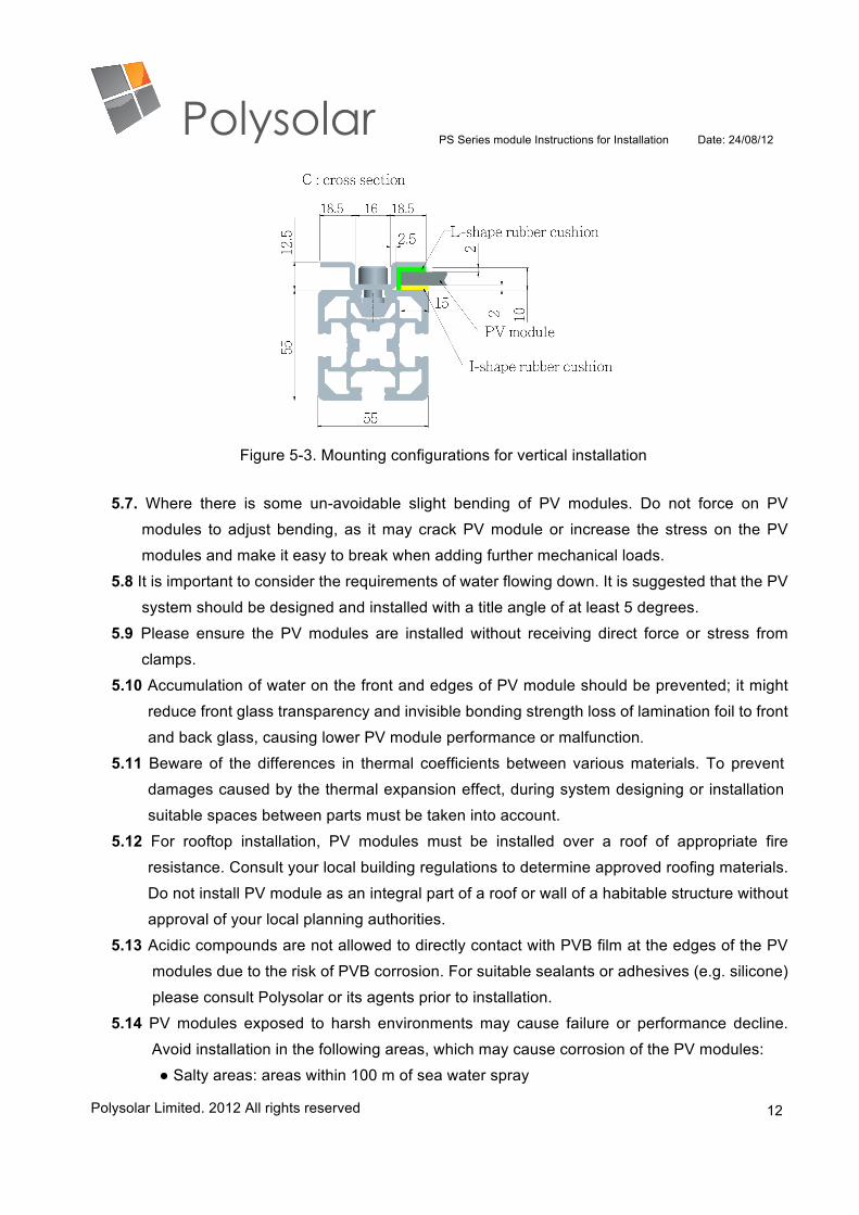
Figure 5-3. Mounting configurations for vertical installation
5.7. Where there is some un-avoidable slight bending of PV modules. Do not force on PV
modules to adjust bending, as it may crack PV module or increase the stress on the PV
modules and make it easy to break when adding further mechanical loads. 5.8 It is important to consider the requirements of water flowing down. It is suggested that the PV
system should be designed and installed with a title angle of at least 5 degrees.
5.9 Please ensure the PV modules are installed without receiving direct force or stress from
clamps.
5.10 Accumulation of water on the front and edges of PV module should be prevented; it might
reduce front glass transparency and invisible bonding strength loss of lamination foil to front
and back glass, causing lower PV module performance or malfunction.
5.11 Beware of the differences in thermal coefficients between various materials. To prevent
damages caused by the thermal expansion effect, during system designing or installation
suitable spaces between parts must be taken into account.
5.12 For rooftop installation, PV modules must be installed over a roof of appropriate fire
resistance. Consult your local building regulations to determine approved roofing materials.
Do not install PV module as an integral part of a roof or wall of a habitable structure without
approval of your local planning authorities.
5.13 Acidic compounds are not allowed to directly contact with PVB film at the edges of the PV
modules due to the risk of PVB corrosion. For suitable sealants or adhesives (e.g. silicone)
please consult Polysolar or its agents prior to installation.
5.14 PV modules exposed to harsh environments may cause failure or performance decline.
Avoid installation in the following areas, which may cause corrosion of the PV modules:
● Salty areas: areas within 100 m of sea water spray
PS Series module Instructions for Installation Date: 24/08/12
Polysolar Limited. 2012 All rights reserved
13
● Sulfurous areas: area near sulfurous volcanos or springs.
●Corrosive chemical areas: areas exposed to corrosive chemicals/gas (e.g. ammonia gas,
etc.)
5.15 Please contact Polysolar or its Agents for further information on installation guidance.
[Underwriter Laboratories (UL) Information for USA and Canada only]
1. The PV modules shall be mounted so that the junction box is in the uppermost position to minimize the
ingress of water.
2. This PV module has a Class C fire rating and must be installed over a roof of appropriate fire resistance. A
minimum slope of 41.67 cm/M (5 in/ft) for installation over a roof is required to maintain the fire class rating.
3. The models have been evaluated by UL for mounting using the following method and hardware:
a. Aluminum or steel mounting clips 6.6 mm tall by 80 mm wide with material 2 mm thick.
b. The clips shall be spaced 400 mm apart on the short edge of the PV module and secured to the underlying
framework using M5 x 12 size bolts and washer, or equivalent.
c. When installed, the clamps "edge capture" area must extend to between 12 to 14 mm from the edge of the
PV module.
d. PV module must be fastened on a durable elastic bedding material - All direct contact of the glass/ PV
module with metal parts of the substructure must be prevented.
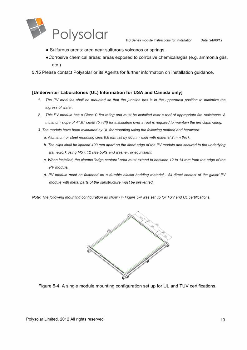
Note: The following mounting configuration as shown in Figure 5-4 was set up for TUV and UL certifications.
Figure 5-4. A single module mounting configuration set up for UL and TUV certifications.
PS Series module Instructions for Installation Date: 24/08/12
Polysolar Limited. 2012 All rights reserved
14
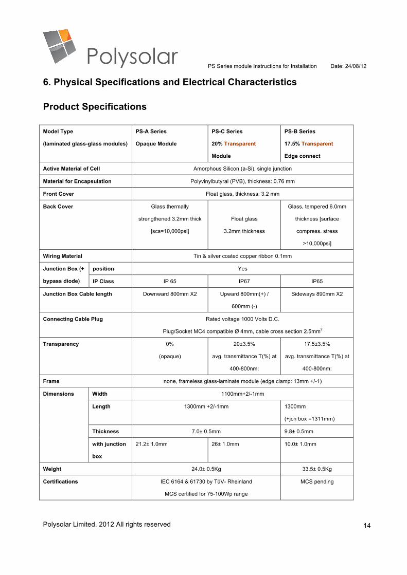
6. Physical Specifications and Electrical Characteristics
Product Specifications Model Type
(laminated glass-glass modules)
PS-A Series
Opaque Module
PS-C Series
20% Transparent
Module
PS-B Series
17.5% Transparent
Edge connect
Active Material of Cell Amorphous Silicon (a-Si), single junction
Material for Encapsulation Polyvinylbutyral (PVB), thickness: 0.76 mm
Front Cover Float glass, thickness: 3.2 mm
Back Cover Glass thermally
strengthened 3.2mm thick
[scs=10,000psi]
Float glass
3.2mm thickness
Glass, tempered 6.0mm
thickness [surface
compress. stress
>10,000psi]
Wiring Material Tin & silver coated copper ribbon 0.1mm
Junction Box (+
bypass diode)
position Yes
IP Class IP 65 IP67 IP65
Junction Box Cable length Downward 800mm X2 Upward 800mm(+) /
600mm (-)
Sideways 890mm X2
Connecting Cable Plug Rated voltage 1000 Volts D.C.
Plug/Socket MC4 compatible Ø 4mm, cable cross section 2.5mm2
Transparency 0%
(opaque)
20±3.5%
avg. transmittance T(%) at
400-800nm:
17.5±3.5%
avg. transmittance T(%) at
400-800nm:
Frame none, frameless glass-laminate module (edge clamp: 13mm +/-1)
Dimensions Width 1100mm+2/-1mm
Length 1300mm +2/-1mm 1300mm
(+jcn box =1311mm)
Thickness 7.0± 0.5mm 9.8± 0.5mm
with junction
box
21.2± 1.0mm 26± 1.0mm 10.0± 1.0mm
Weight 24.0± 0.5Kg 33.5± 0.5Kg
Certifications IEC 6164 & 61730 by TüV- Rheinland
MCS certified for 75-100Wp range
MCS pending
PS Series module Instructions for Installation Date: 24/08/12
Polysolar Limited. 2012 All rights reserved
15
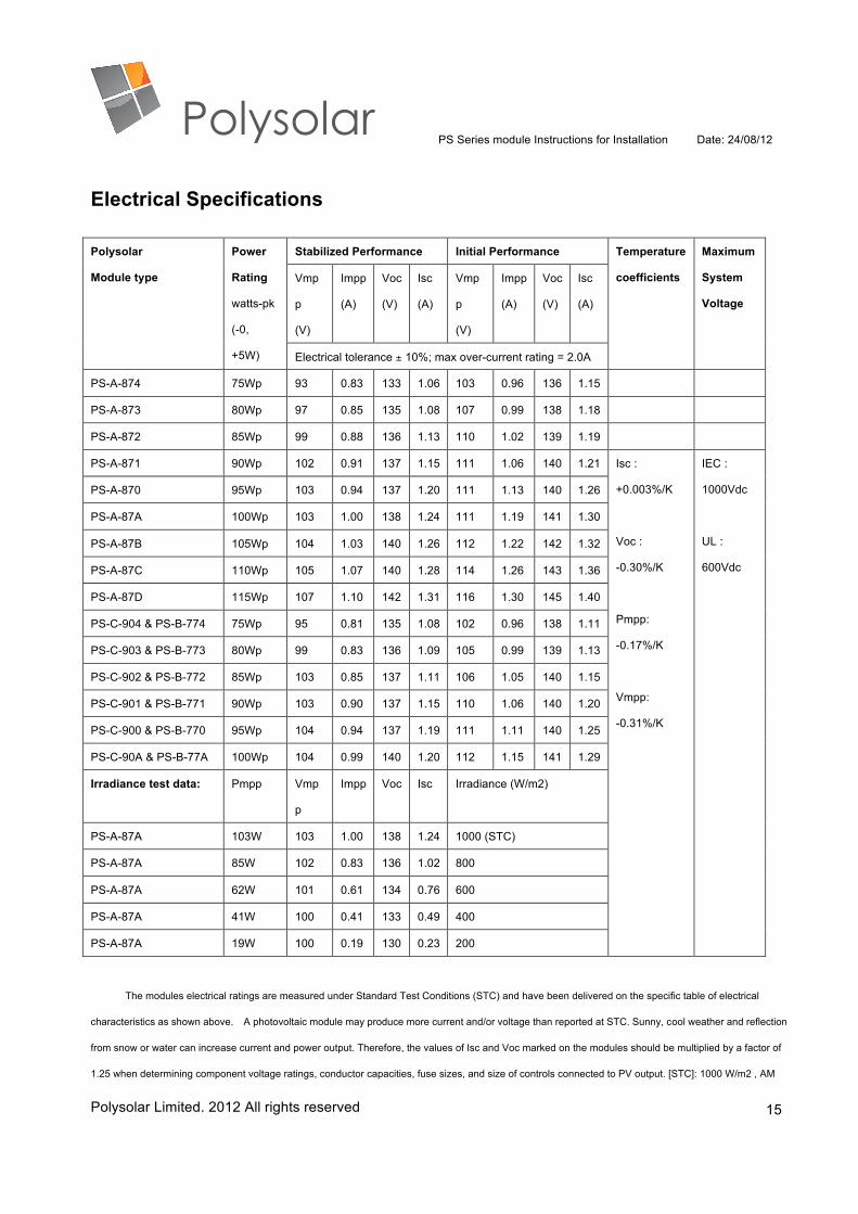
Electrical Specifications Polysolar
Module type
Power
Rating
watts-pk
(-0,
+5W)
Stabilized Performance Initial Performance Temperature
coefficients
Maximum
System
Voltage
Vmp
p
(V)
Impp
(A)
Voc
(V)
Isc
(A)
Vmp
p
(V)
Impp
(A)
Voc
(V)
Isc
(A)
Electrical tolerance ± 10%; max over-current rating = 2.0A
PS-A-874 75Wp 93 0.83 133 1.06 103 0.96 136 1.15
PS-A-873 80Wp 97 0.85 135 1.08 107 0.99 138 1.18
PS-A-872 85Wp 99 0.88 136 1.13 110 1.02 139 1.19
PS-A-871 90Wp 102 0.91 137 1.15 111 1.06 140 1.21 Isc :
+0.003%/K
Voc :
-0.30%/K
Pmpp:
-0.17%/K
Vmpp:
-0.31%/K
IEC :
1000Vdc
UL :
600Vdc
PS-A-870 95Wp 103 0.94 137 1.20 111 1.13 140 1.26
PS-A-87A 100Wp 103 1.00 138 1.24 111 1.19 141 1.30
PS-A-87B 105Wp 104 1.03 140 1.26 112 1.22 142 1.32
PS-A-87C 110Wp 105 1.07 140 1.28 114 1.26 143 1.36
PS-A-87D 115Wp 107 1.10 142 1.31 116 1.30 145 1.40
PS-C-904 & PS-B-774 75Wp 95 0.81 135 1.08 102 0.96 138 1.11
PS-C-903 & PS-B-773 80Wp 99 0.83 136 1.09 105 0.99 139 1.13
PS-C-902 & PS-B-772 85Wp 103 0.85 137 1.11 106 1.05 140 1.15
PS-C-901 & PS-B-771 90Wp 103 0.90 137 1.15 110 1.06 140 1.20
PS-C-900 & PS-B-770 95Wp 104 0.94 137 1.19 111 1.11 140 1.25
PS-C-90A & PS-B-77A 100Wp 104 0.99 140 1.20 112 1.15 141 1.29
Irradiance test data: Pmpp Vmp
p
Impp Voc Isc Irradiance (W/m2)
PS-A-87A 103W 103 1.00 138 1.24 1000 (STC)
PS-A-87A 85W 102 0.83 136 1.02 800
PS-A-87A 62W 101 0.61 134 0.76 600
PS-A-87A 41W 100 0.41 133 0.49 400
PS-A-87A 19W 100 0.19 130 0.23 200
The modules electrical ratings are measured under Standard Test Conditions (STC) and have been delivered on the specific table of electrical
characteristics as shown above. A photovoltaic module may produce more current and/or voltage than reported at STC. Sunny, cool weather and reflection
from snow or water can increase current and power output. Therefore, the values of Isc and Voc marked on the modules should be multiplied by a factor of
1.25 when determining component voltage ratings, conductor capacities, fuse sizes, and size of controls connected to PV output. [STC]: 1000 W/m2 , AM

PS Series module Instructions for Installation Date: 24/08/12
Polysolar Limited. 2012 All rights reserved
16
1.5, 25 .The exactly measured electrical characteristics are shown on the label of the modules. All electrical data is average production data and is subject to
a measuring equipment tolerance; module nominal power is subject to a tolerance of ±2% and power class is sorted on basis of +4.99Wp/-0Wp.
Manufacturer warranty: 5 years product; 10years 90% of power; 25years 80% of power.
PS Series module Instructions for Installation Date: 24/08/12
Polysolar Limited. 2012 All rights reserved
17
7. Electrical Instructions
To avoid electrical shock, ground the support structure of the PV system before wiring the
circuit using a grounding method that meets appropriate local standard or directive requirements
and as advised in MIS3002. Such grounding means should be isolated from live parts by reinforced
insulation during the period of installation and subsequent system operation.
The output voltage and current will exceed the nominal output of the PV modules in the initial
operation. You should be aware of the difference between initial and stabilized performances of the
PV modules. Power output of the PV modules may also increase under different environments and
should be taken into account (see section 6, above).
All of the electrical connections should comply with IEC 61730, UL 1703, or CNS 15118,
and/or applicable local codes/standards.
The system voltage of a PV array should not exceed maximum limit of applicable
codes/standards, e.g.1000 V DC (IEC) or 600 V DC (UL), and inverter for serial connection during
PV modules operating temperature.
Be aware that temperature coefficient and Voc is negative correlation, Voc of PV modules and
voltage of PV array could be higher than magnitude of at STC when the PV modules are operating
in cold environment (lower than 25 ºC).
PV modules may be connected in series, parallel or in a combination of series-parallel to
achieve the desired electrical output as long as certain conditions are met.
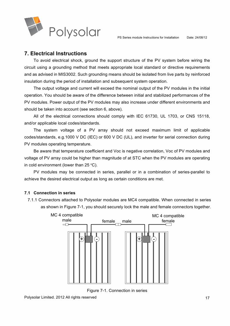
7.1 Connection in series 7.1.1 Connectors attached to Polysolar modules are MC4 compatible. When connected in series
as shown in Figure 7-1, you should securely lock the male and female connectors together.
+ - + -
MC 4 compatiblemale
MC 4 compatiblefemalefemale male
Figure 7-1. Connection in series
PS Series module Instructions for Installation Date: 24/08/12
Polysolar Limited. 2012 All rights reserved
18
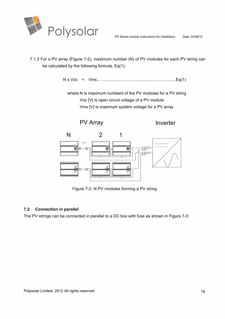
7.1.2 For a PV array (Figure 7-2), maximum number (N) of PV modules for each PV string can
be calculated by the following formula, Eq(1):
N x Voc < Vms…………………………………………………Eq(1)
where N is maximum numbers of the PV modules for a PV string
Voc [V] is open circuit voltage of a PV module
Vms [V] is maximum system voltage for a PV array
1
-
+
-
+
-
+
-
+
-
+
-
+
PV Array Inverter
N 2...
Figure 7-2. N PV modules forming a PV string
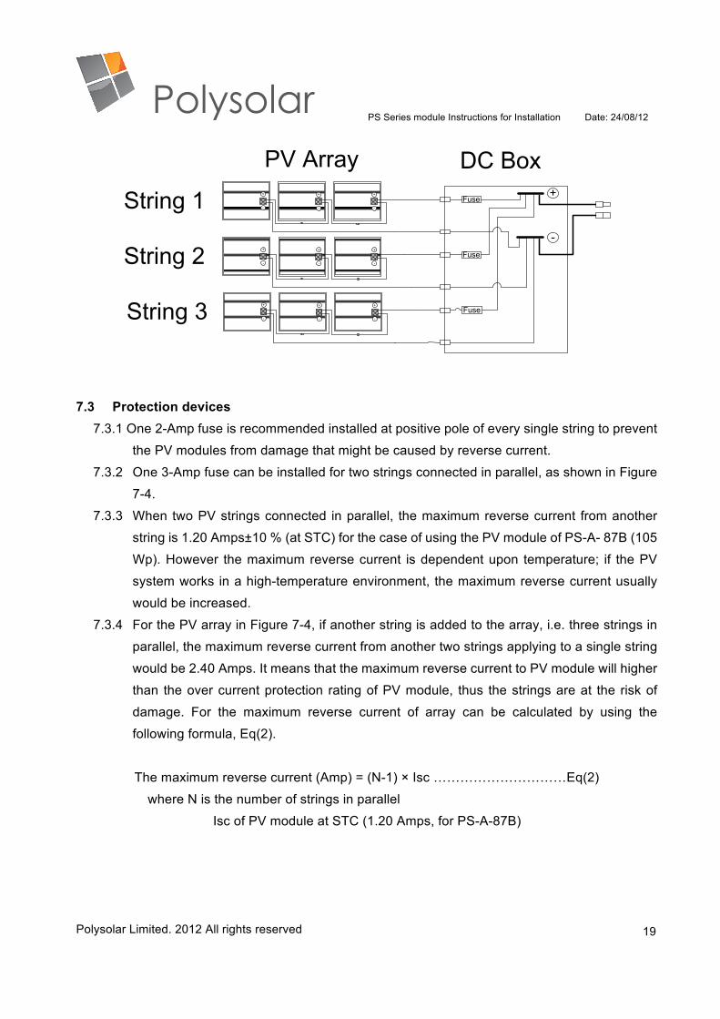
7.2 Connection in parallel The PV strings can be connected in parallel to a DC box with fuse as shown in Figure 7-3:
PS Series module Instructions for Installation Date: 24/08/12
Polysolar Limited. 2012 All rights reserved
19
-
+
-
+
-
+
-
+
-
+
-
+
-
+
-
+
-
+
Fuse
Fuse
Fuse
+
-
DC BoxPV Array
String 1
String 2
String 3
7.3 Protection devices 7.3.1 One 2-Amp fuse is recommended installed at positive pole of every single string to prevent
the PV modules from damage that might be caused by reverse current.
7.3.2 One 3-Amp fuse can be installed for two strings connected in parallel, as shown in Figure
7-4.
7.3.3 When two PV strings connected in parallel, the maximum reverse current from another
string is 1.20 Amps±10 % (at STC) for the case of using the PV module of PS-A- 87B (105
Wp). However the maximum reverse current is dependent upon temperature; if the PV
system works in a high-temperature environment, the maximum reverse current usually
would be increased.
7.3.4 For the PV array in Figure 7-4, if another string is added to the array, i.e. three strings in
parallel, the maximum reverse current from another two strings applying to a single string
would be 2.40 Amps. It means that the maximum reverse current to PV module will higher
than the over current protection rating of PV module, thus the strings are at the risk of
damage. For the maximum reverse current of array can be calculated by using the
following formula, Eq(2).
The maximum reverse current (Amp) = (N-1) × Isc …………………………Eq(2)
where N is the number of strings in parallel
Isc of PV module at STC (1.20 Amps, for PS-A-87B)

PS Series module Instructions for Installation Date: 24/08/12
Polysolar Limited. 2012 All rights reserved
20
Fuse
...
-
+
-
+
-
+
-
+
-
+
-
+
Fuse X
Fuse X
+
-
Theminal fuse Y
PV Array
LNG...
Fuse Y
Inverter
Fuse X (3A)
DC Box
String 01
String N
-
+
-
+
-
+
-
+
-
+
-
+
String N-1
String 02
Figure 7-4. Fuse connection for PV array
7.3.5 For the PV system designed with multiple 2-string arrays, “Fuse X” with 3 Amps rating is
suggested, as shown in Figure 7-4. The protection current rating for “Terminal fuse Y”
between the array and inverter is described as the following formula, Eq(3):
Fuse protection current rating of array = N × Isc × S.. …………………………Eq(3)
where N is the number of strings in parallel
Isc is 1.20 Amps at STC (for model: PS-A-87B)
S is a safety factor of 1.25
For example, when N is 10, the fuse protection current rating is 15.0 Amps. The protection
current rating of common commercial fuses is usually available in a value of integer which
may not exactly meet your need. If exactly the right fuse is not available, a fuse with slightly
larger protection current rating can be use only if the rating as close as possible to the rating
of originally required fuse.
7.3.6 If blocking diodes are required, please confirm that the current capacity and the voltage
limit of the blocking diodes is suitable for the design of PV array.
7.3.7 For lightning protection please refer to MIS3002 or your local codes/regulations.
7.4 Grounding

PS Series module Instructions for Installation Date: 24/08/12
Polysolar Limited. 2012 All rights reserved
21
7.4.1 Risks of fire and electrical shock
The grounding of the PV system is critical for the safety and performance. Failure or
incomplete system grounding may cause fire/electrical shock or reduce the performance
of PV system. The PV modules must only be used in configurations where the negative
polarity of the PV module is connected to ground, or connecting system to the negative
terminal on the DC side of inverter. Details for the grounding should refer to the applicable
local codes for electrical system on specific requirements.
7.4.2 Negative grounding
To avoid TCO (transparent conductive oxide) corrosion, the PV modules must only be
used in configurations where the negative polarity of the PV module is connected to
ground. The grounding can be achieved by using grounding kits available with inverters
as shown in Figure 7-5 (please contact your inverter manufacture for information). Be
aware that the most transformerless inverters cannot fulfill the requirement of negative
grounding.
Fuse
Inverter with grounding kit
-
+
-
+
-
+
-
+
-
+
-
+
-
+
-
+
-
+
Fuse
Fuse
Fuse
+
-
DC BoxPV ArrayLNG
Figure 7-5. Negative grounding by using grounding kit of inverter
The grounding wire can be completely installed by using the ground lug. No-stainless
steel metal parts, such as screws, nuts, and washers should be used.
7.4.3 Warranty exclusion
Failure to comply with the requirement of grounding will invalidate warranty for the PV
modules. Contact your installer or Polysolar if any questions about grounding remain.
PS Series module Instructions for Installation Date: 24/08/12
Polysolar Limited. 2012 All rights reserved
22
7.5 Wiring and connectors 7.5.1 Only connect PV modules in series with the same type, and avoid using different power
categories.
7.5.2 Don’t open junction box or remove connectors from the solar cables.
7.5.3 The solar cables are equipped with the MC4 compatible solar-lock pin-and-socket
connectors.
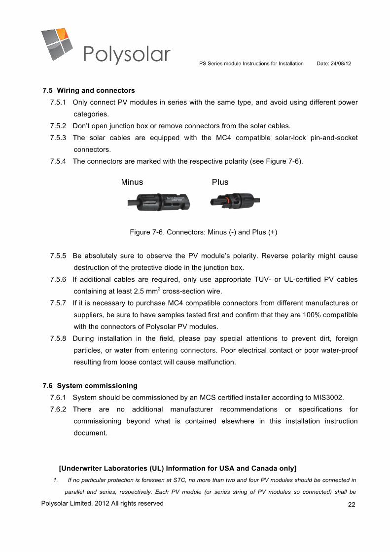
7.5.4 The connectors are marked with the respective polarity (see Figure 7-6).
Figure 7-6. Connectors: Minus (-) and Plus (+)
7.5.5 Be absolutely sure to observe the PV module’s polarity. Reverse polarity might cause
destruction of the protective diode in the junction box.
7.5.6 If additional cables are required, only use appropriate TUV- or UL-certified PV cables
containing at least 2.5 mm2 cross-section wire.
7.5.7 If it is necessary to purchase MC4 compatible connectors from different manufactures or
suppliers, be sure to have samples tested first and confirm that they are 100% compatible
with the connectors of Polysolar PV modules.
7.5.8 During installation in the field, please pay special attentions to prevent dirt, foreign
particles, or water from entering connectors. Poor electrical contact or poor water-proof
resulting from loose contact will cause malfunction.
7.6 System commissioning 7.6.1 System should be commissioned by an MCS certified installer according to MIS3002.
7.6.2 There are no additional manufacturer recommendations or specifications for
commissioning beyond what is contained elsewhere in this installation instruction
document.
[Underwriter Laboratories (UL) Information for USA and Canada only] 1. If no particular protection is foreseen at STC, no more than two and four PV modules should be connected in
parallel and series, respectively. Each PV module (or series string of PV modules so connected) shall be
PS Series module Instructions for Installation Date: 24/08/12
Polysolar Limited. 2012 All rights reserved
23
provided with the maximum series fuse.
2. If the PV modules are mounted with frames, the grounding method of the frame of arrays should comply with the
NEC, article 250.
3. A photovoltaic module may produce more current and/or voltage than reported at STC. Sunny, cool weather and
reflection from snow or water can increase current and power output. Therefore, the values of Isc and Voc
marked on the UL series PV module should be multiplied by a factor of 1.25 when determining component
voltage ratings, conductor ampacities, fuse sizes, and size of controls connected to PV output. (Otherwise, see
section 690-8 of the National Electric Code for an additional multiplying factor.)
4. Refer to Section 690-8 of the National Electric Code for an additional multiplying factor of 1.25 which may be
applicable.