instruction manual slit lamp sl-3g · this instruction manual covers an overview of the basic...
TRANSCRIPT

INSTRUCTION MANUALSLIT LAMP
SL-3G

INTRODUCTIONThank you for purchasing the TOPCON SL-3G Slit Lamp.
This instrument is used for the magnified observation of the eye and its various struc-tures.
This SL-3G has the following features:• Smooth mechanical movements• Bright and clear observation of the eye with natural color rendition• Optical system to enhance natural color and resolution
This Instruction Manual covers an overview of the basic operation, troubleshooting,checking, maintenance and cleaning of the SL-3G Slit Lamp.To get the best results from this instrument, read "Displays for Safe Use" and "SafetyCautions".Keep this Instruction Manual close at hand for future reference.
[Warning]To avoid injury to the patient’s eye and nose, pay particular attention whileoperating the instrument body.(The patient may be injured.)
[Caution]This instrument must not be used for the following patients:
• Patients who are hypersensitive to light• Patients who recently underwent photodynamic therapy (PDT)• Patients taking medication that causes photosensitivity.
���� ���� �� ���� ��� �� �� ������ ������� ���� ���� ������� ������ � ��� ���������� ��� ������ ����� ������ �������������� ���� �� ������� � ��� �� �� ������ ������� � �� � ���� � �������� � ��� ���� � ����� �� ��� � ��� �� ���� �!��������� � ���� �� � ���� �������� �� � ���� � ���� � ������ ��� �� � ��� ����
�����
WARNING : Handling the cord on this product or cords associated with accessories soldwith this product, will expose you to lead, a chemical known to the State of California tocause birth detects or other reproductive harm. Wash hands after handling.
CAUTION : Federal laws restricts this device to the sale by or on the order of a physician.
1�������
CAUTIONS FOR USEImportant cautions
Use this instrument carefully on the following patients:• Patients who have epidemic corneitis, conjunctivitis or any other infectious disease• Patients who are taking medications that cause light hypersensitivity.
Basic cautionsBe careful not to let the patient touch this instrument. The patient's hand may be pinched by themovable part.To avoid injury or fire caused by electric shock, turn off the power switch and unplug the powercord. Then, replace the fuse with the rated one.To avoid injury caused by electric shock, turn off the power switch when replacing the lamp.To avoid burns caused by heat, do not replace the lamp with a new one immediately after itgoes off.When operating the base unit, please note the following:• Beware of catching fingers in the moving parts.• Avoid hitting the patient's eyes or nose.To avoid injury to the patient's head, incline the illumination unit slowly while holding the baseunit.
DisposalDispose of the instrument according to local disposal and recycling laws.
ENVIRONMENTAL CONDITIONS FOR USETemperature : 10°C - 40°CHumidity : 30% - 90% (without dew condensation)Air pressure : 700hPa - 1060hPa
STORAGE CONDITIONS1. Environmental conditions (without package)
∗Temperature : 10°C - 40°CHumidity : 10% - 95% (without dew condensation)Air pressure : 700hPa - 1060hPa∗ THIS INSTRUMENT DOES NOT MEET THE TEMPERATURE REQUIREMENTS OF
ISO 15004-1 FOR STORAGE. DO NOT STORE THIS INSTRUMENT IN CONDITIONSWHERE THE TEMPERATURE MAY RISE ABOVE 40°C OR FALL BELOW 10°C.
2. When storing the instrument, ensure that the following conditions are met:(1) The instrument should not be splashed with water.(2) Store the instrument where environmental conditions are appropriate.(3) Do not store or transport the instrument on a slope or uneven surface or in an area
where it is subject to vibrations or instability.(4) Do not store the instrument where chemicals are stored or gas is generated.
3. Usage period8 years from delivery providing regular maintenance is performed (according to the self-cer-tification [TOPCON data])
2

ENVIRONMENTAL CONDITIONS FOR PACKAGING IN STORAGETemperature : -20°C - 50°CHumidity : 10% - 95%
ENVIRONMENTAL CONDITIONS FOR PACKAGING IN TRANSPORTATIONTemperature : -40°C - 70°CHumidity : 10% - 95%
CHECKPOINTS FOR MAINTENANCE1. Regularly maintain and check the instrument and its parts.2. When using the instrument after a prolonged period of inactivity, confirm normal and safe
operation beforehand.3. Keep the objective lens, eyepiece and mirror free from finger prints and dust.4. When not in use, protect the instrument with the dust cover.5. If the objective lens, eyepiece or mirror is stained, clean it following "Cleaning lenses and
mirrors" in this Instruction Manual.
3

DISPLAYS FOR SAFE USEIn order to ensure the safe use of the product and to prevent danger to the operator and others, ordamage to property, important warnings are placed on the product and inserted in the instructionmanual.It is recommended for all users to take note of the meaning of the following displays and iconsbefore reading the "Safety Cautions" and text.
DISPLAYS
ICONS
DISPLAY MEANING
WARNING Ignoring or disregarding this notice could lead to death or seri-ous injury.
CAUTION Ignoring or disregarding this display may lead to personal injuryor physical damage.
• Injury refers to cuts, bruises, sprains, fractures, burns, electric shocks, etc.• Physical damage refers to damage to buildings, equipment or furniture.
ICON MEANING
This indicates Prohibition.Specific content is expressed with words or an icon either insertedin the icon itself or located next to the icon.
This indicates Mandatory Action.Specific content is expressed with words or an icon either insertedin the icon itself or located next to the icon.
This icon indicates Hazard Alerting (Warning).Specific content is expressed with words or an icon either insertedin the icon itself or located next to the icon.
4
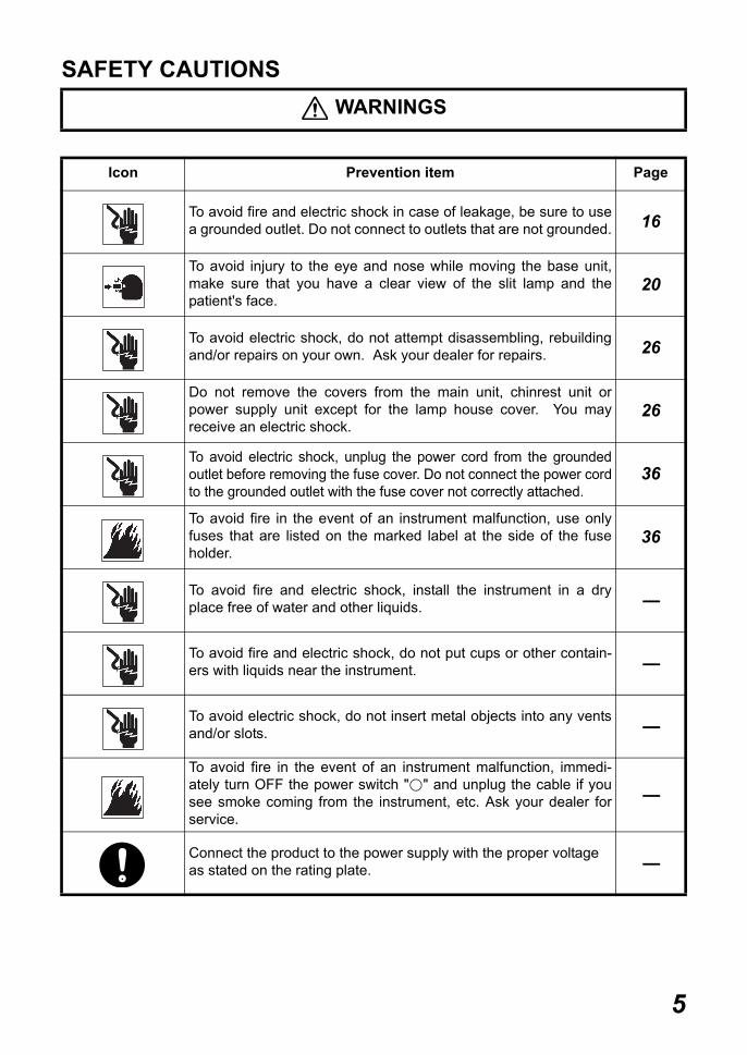
SAFETY CAUTIONS WARNINGS
Icon Prevention item Page
To avoid fire and electric shock in case of leakage, be sure to usea grounded outlet. Do not connect to outlets that are not grounded. 16
To avoid injury to the eye and nose while moving the base unit,make sure that you have a clear view of the slit lamp and thepatient's face.
20
To avoid electric shock, do not attempt disassembling, rebuildingand/or repairs on your own. Ask your dealer for repairs. 26
Do not remove the covers from the main unit, chinrest unit orpower supply unit except for the lamp house cover. You mayreceive an electric shock.
26
To avoid electric shock, unplug the power cord from the groundedoutlet before removing the fuse cover. Do not connect the power cordto the grounded outlet with the fuse cover not correctly attached.
36
To avoid fire in the event of an instrument malfunction, use onlyfuses that are listed on the marked label at the side of the fuseholder.
36
To avoid fire and electric shock, install the instrument in a dryplace free of water and other liquids. -----
To avoid fire and electric shock, do not put cups or other contain-ers with liquids near the instrument. -----
To avoid electric shock, do not insert metal objects into any ventsand/or slots. -----
To avoid fire in the event of an instrument malfunction, immedi-ately turn OFF the power switch " " and unplug the cable if yousee smoke coming from the instrument, etc. Ask your dealer forservice.
-----
Connect the product to the power supply with the proper voltageas stated on the rating plate. -----
5

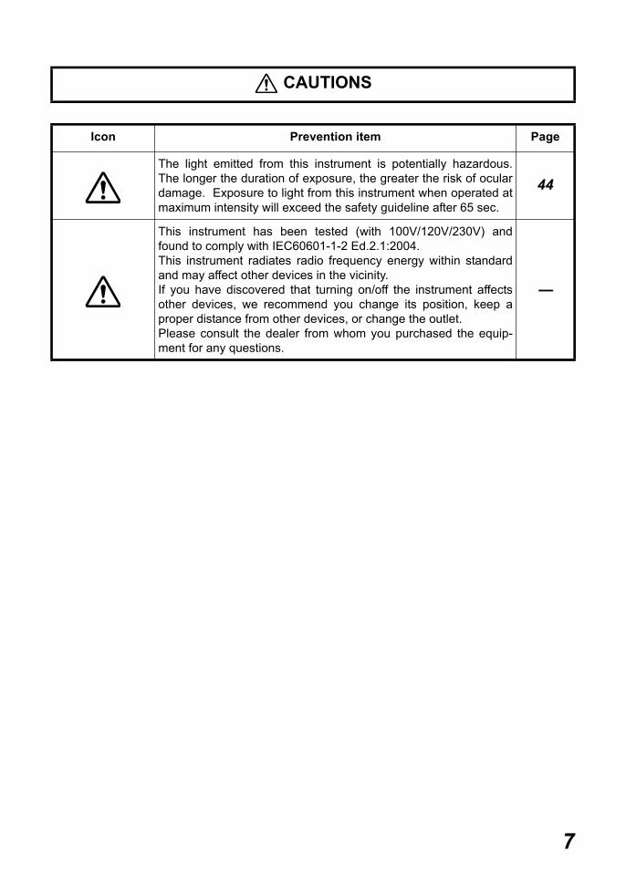
CAUTIONS
Icon Prevention item Page
To prevent damage and injuries, install the instrument on a levelsurface. 16
To avoid electric shock, do not handle the plugs with wet fingers. 16
For the safety of the operator and the patient, do not place fingersbetween moving parts. 20
To avoid injury to the patient’s head, incline the illumination unitslowly while holding the base unit. 21
To avoid causing discomfort to the patient or any damage to thepatient's eye, keep the illumination at its minimum duringadjustment.
21
When replacing the lamp, switch off the power supply and removethe power cord to avoid electric shock. 35
Beware of high temperatures when replacing the lamp immedi-ately after switching it off: these could cause burns. 35
Before carrying out daily care, remove the power cord (to avoidelectric shock) and wait until the main unit has cooled (to avoidburns).
38
Do not touch parts inside the lamp house cover during operationand immediately after switching off the power supply: this couldcause burns.
38
To prevent falling during use and movement, secure optionalaccessories. 40
To prevent the movable parts from hitting anyone's body, tightenand fix the illumination arm locking knob, microscope arm lockingknob and base locking knob before moving the instrument.
25
6
CAUTIONS
Icon Prevention item Page
The light emitted from this instrument is potentially hazardous.The longer the duration of exposure, the greater the risk of oculardamage. Exposure to light from this instrument when operated atmaximum intensity will exceed the safety guideline after 65 sec.
44
This instrument has been tested (with 100V/120V/230V) andfound to comply with IEC60601-1-2 Ed.2.1:2004.This instrument radiates radio frequency energy within standardand may affect other devices in the vicinity.If you have discovered that turning on/off the instrument affectsother devices, we recommend you change its position, keep aproper distance from other devices, or change the outlet.Please consult the dealer from whom you purchased the equip-ment for any questions.
-----
7
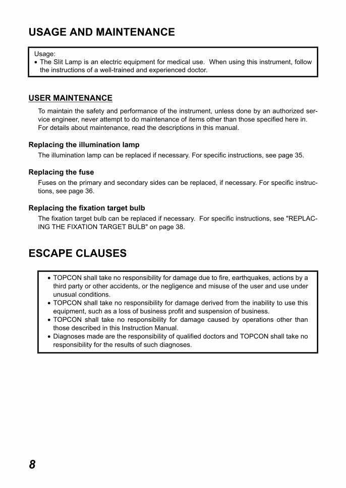
USAGE AND MAINTENANCE
USER MAINTENANCETo maintain the safety and performance of the instrument, unless done by an authorized ser-vice engineer, never attempt to do maintenance of items other than those specified here in.For details about maintenance, read the descriptions in this manual.
Replacing the illumination lampThe illumination lamp can be replaced if necessary. For specific instructions, see page 35.
Replacing the fuseFuses on the primary and secondary sides can be replaced, if necessary. For specific instruc-tions, see page 36.
Replacing the fixation target bulbThe fixation target bulb can be replaced if necessary. For specific instructions, see "REPLAC-ING THE FIXATION TARGET BULB" on page 38.
ESCAPE CLAUSES
Usage:• The Slit Lamp is an electric equipment for medical use. When using this instrument, follow
the instructions of a well-trained and experienced doctor.
• TOPCON shall take no responsibility for damage due to fire, earthquakes, actions by athird party or other accidents, or the negligence and misuse of the user and use underunusual conditions.
• TOPCON shall take no responsibility for damage derived from the inability to use thisequipment, such as a loss of business profit and suspension of business.
• TOPCON shall take no responsibility for damage caused by operations other thanthose described in this Instruction Manual.
• Diagnoses made are the responsibility of qualified doctors and TOPCON shall take noresponsibility for the results of such diagnoses.
8
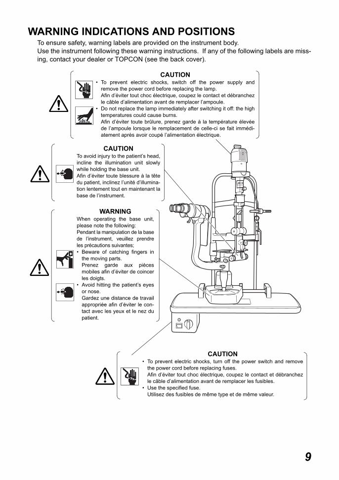
WARNING INDICATIONS AND POSITIONSTo ensure safety, warning labels are provided on the instrument body.Use the instrument following these warning instructions. If any of the following labels are miss-ing, contact your dealer or TOPCON (see the back cover).
CAUTION• To prevent electric shocks, switch off the power supply and
remove the power cord before replacing the lamp.Afin d’éviter tout choc électrique, coupez le contact et débranchezle câble d’alimentation avant de remplacer l’ampoule.
• Do not replace the lamp immediately after switching it off: the hightemperatures could cause burns.Afin d’éviter toute brûlure, prenez garde à la température élevéede l’ampoule lorsque le remplacement de celle-ci se fait immédi-atement après avoir coupé l’alimentation électrique.
CAUTION• To prevent electric shocks, turn off the power switch and remove
the power cord before replacing fuses.Afin d’éviter tout choc électrique, coupez le contact et débranchezle câble d’alimentation avant de remplacer les fusibles.
• Use the specified fuse.Utilisez des fusibles de même type et de même valeur.
CAUTIONTo avoid injury to the patient’s head,incline the illumination unit slowlywhile holding the base unit.Afin d’éviter toute blessure à la têtedu patient, inclinez l’unité d’illumina-tion lentement tout en maintenant labase de l’instrument.
WARNINGWhen operating the base unit,please note the following:Pendant la manipulation de la basede l’instrument, veuillez prendreles précautions suivantes;• Beware of catching fingers in
the moving parts.Prenez garde aux piècesmobiles afin d’éviter de coincerles doigts.
• Avoid hitting the patient’s eyesor nose.Gardez une distance de travailappropriée afin d’éviter le con-tact avec les yeux et le nez dupatient.
9

CONTENTSINTRODUCTION .................................................................................................................1DISPLAYS FOR SAFE USE ................................................................................................4SAFETY CAUTIONS ...........................................................................................................5USAGE AND MAINTENANCE .............................................................................................8ESCAPE CLAUSES .............................................................................................................8WARNING INDICATIONS AND POSITIONS ......................................................................9
CONFIGURATIONNAMES OF MAIN BODY COMPONENTS ........................................................................12CONFIGURATION OF PARTS IN CONTACT WITH THE PATIENT ................................12STANDARD ACCESSORIES ............................................................................................13
BASIC OPERATIONSFLOW OF OPERATION ....................................................................................................15
PREPARATIONSCONNECTING THE POWER CORD ................................................................................16TURNING ON THE POWER .............................................................................................16ADJUSTING THE DIOPTER AND PUPILLARY DISTANCE (PD) ....................................17
OPERATION PROCEDUREFIXING THE PATIENT’S FACE AND FIXATION ...............................................................18OPERATING THE MICROSCOPE UNIT ...........................................................................19OPERATING THE BASE AND FOCUSING ......................................................................20OPERATING THE ILLUMINATION UNIT .........................................................................21ENDING PROCEDURE .....................................................................................................24
CAUTION WHEN MOVING THE INSTRUMENT ..........................................25
TROUBLESHOOTINGTROUBLESHOOTING GUIDE ..........................................................................................26
SPECIFICATIONS & PERFORMANCESPECIFICATIONS .............................................................................................................27ELECTROMAGNETIC COMPATIBILITY ...........................................................................28ELECTRIC RATING ...........................................................................................................31SYSTEM CLASSIFICATION ..............................................................................................32DIMENSIONS AND WEIGHT ............................................................................................32PURPOSE OF USE ...........................................................................................................32OPERATION PRINCIPLE ..................................................................................................32
MAINTENANCE AND CHECKUPSMAINTAINING ACCURACY ..............................................................................................33PERIODIC MAINTENANCE ..............................................................................................33USER MAINTENANCE ITEMS ..........................................................................................34DAILY CARE ......................................................................................................................34PLACING AN ORDER FOR CONSUMABLES ..................................................................34REPLACING ILLUMINATION LAMPS ...............................................................................35REPLACING FUSES .........................................................................................................36
10
RESTOCKING CHINREST TISSUE ..................................................................................38REPLACING THE FIXATION TARGET BULB ..................................................................38DAILY CARE ......................................................................................................................38
OPTIONAL ACCESSORIESSYSTEM CONFIGURATION .............................................................................................4010× MEASURING EYEPIECE ...........................................................................................41HRUBY LENS ....................................................................................................................41
REFERENCE MATERIALSHAPE OF PLUG ..............................................................................................................42SYMBOL ............................................................................................................................42ADJUSTABLE AUTOMATIC INSTRUMENT TABLE .........................................................42
RELATION BETWEEN SETTING OF ILLUMINATIONLEVEL AND MAXIMUM RADIANCE ....................................................................43
INFORMATION ABOUT THE OPTICAL RADIATION HAZARD TO THE USER .............................................................................................44
11

CONFIGURATION
NAMES OF MAIN BODY COMPONENTS
CONFIGURATION OF PARTS IN CONTACT WITH THE PATIENTForehead rest : Polyamide resinChinrest : Polyamide resin
����� ��� �� �
� ������� �� �
�� ����� �� �
���� �� �
���� �� �
�������� ��
��� ��
�� �� ������
������ ����� ��� �
��������
��� ������� ��� ��� �����
�������������� � ����
��� �� ������
����� �� ����� ����
������ ��� �������� � � ��
�� ������
! ��� ����
��������� �������� � � ��
"���� ������� � ��
#��� ����
#���� ����
$������� �����
!������%�� �� �������� �� ���
����� ������ �����
!������%�� �� ���� ��� � ��
��&��� ����
'������� ������
����� �� ()��� *
����� �� ������()��� *
�� �� ��� � � ��
������ ��� � ��� ��� �����
�� ���� �� ��� � ��
�� ��� �����
"�� ����� � � ��
'��� �����
"��
+����
)������� ��
#���
��� ��� �� �� �
������ ��� ���� ����
��� ���� ��� ������!� �� ����
#������ ��� ������
��&��� ���� ����
12CONFIGURATION

STANDARD ACCESSORIESMake sure that all the following standard accessories are included.Figures in parentheses are the quantities.
Chinrest tissue (1) Dust cover (1)
Test rod (1) Phillips screwdriver (1)
Spare illumination lamp (1) Slotted screwdriver (large) (1)
Spare socket (1) Slotted screwdriver (small) (1)
Luminous fixation target (1) Hexagonal wrench M3/M4 (2)
Spare fixation target bulb (1) Spanner (1) ∗
Cleaning brush (1) Spare chinrest tissue pin (2)
13CONFIGURATION

∗ The spanner is provided only when the table is used.For optional accessories, see "OPTIONAL ACCESSORIES" on page 40.
Spare fusePrimary side (4)Secondary side (1)
16× eyepiece (2)(16× eyepiece is optionally available in some regions)
Accessory case (1) Square mirror (1)
Power cord (1) "Instruction manual" and"Unpacking and assembly" (1 each)
�����
14CONFIGURATION

15BASIC OPERATIONS
BASIC OPERATIONS
FLOW OF OPERATIONBasic observation procedure
Other types of observation• Observation by adjusting the slit width• Observation by changing the aperture and slit length• Observation by turning the slit• Observation by swinging the slit sideways• Observation by inclined illumination• Observation by ND filter• Observation by Red-Free filter• Observation by blue filter
Adjusting the diopter and pupillary distance (P.17)
Operating the microscope unit (P.19)
Operating the illumination unit (P.21)
Operating the base and focusing (P.20)
Fixing the patient's face and fixation (P.18)
Turning on the power (P.16)
Ending procedure (P.24)

PREPARATIONS
CONNECTING THE POWER CORD
1 Make sure that the "POWER switch" is OFF ( ) on the power supply unit.
2 Connect the power cord to the AC connector on the power supply unit.
3 Make sure that the cables are connected to the illumination lamp plug and the fixation tar-get plug on the rear surface of the power supply unit.
4 Check if the plug is inserted into the lamp house cover securely.
5 Plug the power cord into the grounded outlet.
TURNING ON THE POWER
1 Connect the power cord.
2 Turn ON ( ) the "POWER switch".
WARNING To avoid fire and electric shock in case of leakage, be sure to use agrounded outlet. Do not connect to outlets that are not grounded.
CAUTION To prevent damage and injuries, install the instrument on a level sur-face.
CAUTION To avoid electric shock, do not handle the plugs with wet fingers.
Fixation target plugIllumination lamp plug
Lamp house coverPlug
16PREPARATIONS

ADJUSTING THE DIOPTER AND PUPILLARY DISTANCE (PD)
1 Insert the "test rod" into the rotation shaft cavity, and set the black face square with themicroscope.
2 Place the "brightness adjustment knob" in an intermediate position.
3 Adjust the illumination to φ10mm by adjusting the "slit width control knob" and "aperture/slitlength control knob".
4 Turn the "diopter adjusting ring" of the "eyepiece" at one side fully counter-clockwise.
5 Turn the "diopter adjusting ring" clockwise and stop when the "test rod" can be clearlyseen.The values -8 to +8 on the scale indicate the diopter (D) on "10× eyepiece". -10 to +10indicate the diopter (D) on "16× eyepiece".
6 Adjust the diopter of another "eyepiece" in the same way as above.
7 After adjusting the diopter, turn the "slit width control knob" until the slit width is about1mm, then check if the slit image projected on the "test rod" is properly in focus.
8 Holding the "prism box", look through the "eyepiece" with both eyes, and adjust the pupil-lary distance so that the image projected on the "test rod" can be seen without diplopia(double vision), and appear to be three dimensional.
NOTE To ensure sharp observation of slit images, always carry out thediopter and PD adjustments.
Test rod
Prism box
Diopter adjusting ringDiopter scale
10× eyepiece
17PREPARATIONS

OPERATION PROCEDURE
FIXING THE PATIENT’S FACE AND FIXATION
1 Place the patient's chin on the "chinrest" with his or her forehead against the "foreheadrest".
2 By rotating the "chinrest adjuster", align the patient's eye with the "canthus marker" on thechinrest frame.
3 Ask the patient to look at the fixation target with the eye that is not being examined.To change the patient's fixation point, hold the fixation target at the end opposite to the tar-get and adjust accordingly.
When using the fixation target with diopter adjustment, slide the diopter adjusting ring sothat the patient can see the following target ( ). The ring target can be adjusted within arange of -15D to +10D.The luminous fixation target is used for myopia of -15D or more.When replacing targets, remove the target by pulling gently while supporting the oppo-site end.
Forehead rest
Canthus marker
Chinrest
Chinrest adjuster
Fixation target with diopter adjustment
Fixation target lever
Diopter adjusting ring
Luminous fixation target
18OPERATION PROCEDURE

OPERATING THE MICROSCOPE UNITTurn the "magnification changer lever" to set a desired magnification value.
For the overall magnification in conjunction with magnification marks of the "magnifica-tion changer lever" and "eyepiece", see page 27.
Magnification changer lever
19OPERATION PROCEDURE

OPERATING THE BASE AND FOCUSING
1 For major horizontal movements, hold the "control lever" in the upright position and movethe entire base.
2 For fine adjustments, move the "control lever" in the required direction.
3 The base can be raised by turning the "control lever" clockwise, and lowered by turning the"control lever" counter-clockwise.
4 To fix the "base", fasten the base "base locking knob".
• Rough focusing is carried out with major movements, following step 1 to 3.• Fine focusing is done with the microscope, following steps 2 and 3.
CAUTION To avoid injury to the eye and nose while moving the base unit, makesure that you have a clear view of the slit lamp and the patient's face.
CAUTION For the safety of the operator and the patient, do not place fingersbetween moving parts.
NOTE To prevent dropping the base locking knob from the base, do notloosen the knob too much.
Base locking knob
Base
Control lever
20OPERATION PROCEDURE

OPERATING THE ILLUMINATION UNIT
Adjusting the brightnessTurn the "brightness adjustment knob".The brightness of the illumination light can be adjusted by three stages.
Adjusting the slit widthTurn the "slit width control knob".The slit width can be changed gradually between 0 and 9mm (9mm=circle).
Changing the aperture/slit lengthTurn the "aperture/slit length control knob".When the slit is fully opened, 7 types of spot illumination (φ9, φ8, φ5, φ3, φ2, φ1, φ0.2mm) areavailable. The slit length can be changed gradually from 1mm to 8mm.
The spot illumination size and slit length are displayed on the "aperture/slit length displaywindow".
CAUTION To avoid injury to the patient's head, incline the illumination unit slowlywhile holding the base unit.
CAUTION To avoid causing discomfort to the patient or any damage to thepatient's eye, keep the illumination at its minimum during adjustment.
NOTE
• Adjust the slit width according to the results of the investigation.• The slit-width scale should be used as a guideline.• When using the square mirror, incline the illumination unit at least
10°.• To protect the patient, use the heat absorption filter, as required.
Brightness adjustment knob
Slit width control knob
Aperture/slit length display window
Aperture/slit length control knob
21OPERATION PROCEDURE

Turning the slitHorizontally rotate the "aperture/slit length control knob".This directly changes the slit image from vertical to horizontal. In this mode, the slit angle canbe read on the angle scale.
Swinging the slit sidewaysLoosen the "slit centering knob" and swing the illumination unit right and left.This provides indirect illumination displacing the slit light from the microscope center.By fastening the "slit centering knob", the slit light returns to the center of the vision field.
This function is used for scanning observation and observation with indirect illumination.
Inclined illuminationPress to unlock the "illumination inclination lever" and pull.The illumination unit is inclined for inclined illumination up to 20° in 5° steps.
This function is used for observing a horizontal cross section, and for corner angle andfundus observation.
Aperture/slit length control knob
Slit-angle scale
Slit centering knob
Illumination inclination lever
22OPERATION PROCEDURE
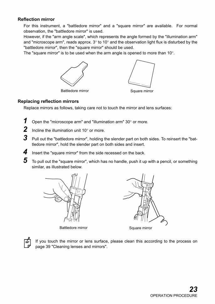
Reflection mirrorFor this instrument, a "battledore mirror" and a "square mirror" are available. For normalobservation, the "battledore mirror" is used.However, if the "arm angle scale", which represents the angle formed by the "illumination arm"and "microscope arm", reads approx. 3° to 10° and the observation light flux is disturbed by the"battledore mirror", then the "square mirror" should be used.The "square mirror" is to be used when the arm angle is opened to more than 10°.
Replacing reflection mirrorsReplace mirrors as follows, taking care not to touch the mirror and lens surfaces:
1 Open the "microscope arm" and "illumination arm" 30° or more.
2 Incline the illumination unit 10° or more.
3 Pull out the "battledore mirror", holding the slender part on both sides. To reinsert the "bat-tledore mirror", hold the slender part on both sides and insert.
4 Insert the "square mirror" from the side recessed on the back.
5 To pull out the "square mirror", which has no handle, push it up with a pencil, or somethingsimilar, as illustrated below.
If you touch the mirror or lens surface, please clean this according to the process onpage 39 "Cleaning lenses and mirrors".
Battledore mirror Square mirror
Battledore mirror Square mirror
23OPERATION PROCEDURE

Changing filtersMove the "filter selector lever" right and left to select the required filter from the 5 types.
ENDING PROCEDURE
1 Turn OFF ( ) the "POWER switch" on the power supply unit.
2 To prevent the base from moving unexpectedly, tighten the "base locking knob" and fix it.
When the instrument is not in use for a long time, unplug its power cord from the outlet.
No filter
Heat-absorption filter
ND filter Red-free filter Blue filter
Green-colored Blue-colored
Aperture/slit length display window
Filter selector lever
Aperture/slit length control knob
24OPERATION PROCEDURE

25CAUTION WHEN MOVING THE INSTRUMENT
CAUTION WHEN MOVING THE INSTRUMENT
Before moving the SL-3G by placing it on a movable item such as an automatic instrumenttable, tighten and fix "illumination arm locking knob", "microscope arm locking knob" and "baselocking knob" securely.
CAUTIONTo prevent the movable parts from hitting anyone's body, tighten andfix the illumination arm locking knob, microscope arm locking knoband base locking knob before moving the instrument.
Illumination arm locking knob
Microscope arm locking knob
Base locking knob

26TROUBLESHOOTING
TROUBLESHOOTING
TROUBLESHOOTING GUIDE
If you suspect a problem, check the possible cause by means of the check list below.If the check list below does not solve the problem, or if the problem is not included in the list,contact your dealer or TOPCON (see the back cover).
Check List
WARNING To avoid electric shocks, do not attempt disassembling, rebuildingand/or repairs on your own. Ask your dealer for repairs.
WARNINGDo not remove the covers from the main unit, chinrest unit or powersupply unit except for the lamp house cover. You may receive anelectric shock.
Problem Possible cause Check PageIllumination lampdoes not work.
Cable is disconnected. Connect the cable to the outletcorrectly.
16
POWER switch is OFF. Turn ON ( ) POWER switch. 16Plug of lamp house cover isswitched off.
Insert the plug correctly. 16
The fuses have blown out. Replace them with new fuses. 34, 3637
Illumination lamp is broken. Replace it with a new illumina-tion lamp.
35
Socket has deteriorated. Replace it with a new socket. 36The illumination lamp plug onthe power supply unit isswitched off.
Insert the plug correctly. 16
Illumination field isnot uniform/is shady/is dark.
Filter selector lever is out ofposition.
Click filter selector lever. 24
Fuse blows. Rated capacity of fuse is incor-rect.
Use fuse with correct rating &authorized fuse.
34, 3637
Slit width narrows byitself.
Slit width control knob torquehas been decreased.
Carry out "Adjusting the slitwidth control knob torque."
33
The fixation targetdoes not light.
The fixation target plug on thepower supply unit is switchedoff.
Insert the plug correctly. 16
SPECIFICATIONS & PERFORMANCE
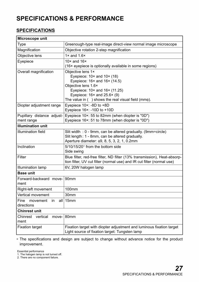
SPECIFICATIONS
∗ The specifications and design are subject to change without advance notice for the productimprovement.
Microscope unitType Greenough-type real-image direct-view normal image microscopeMagnification Objective rotation 2-step magnificationObjective lens 1× and 1.6×Eyepiece 10× and 16×
(16× eyepiece is optionally available in some regions)Overall magnification Objective lens 1×
Eyepiece: 10× and 10× (18)Eyepiece: 16× and 16× (14.5)
Objective lens 1.6×Eyepiece: 10× and 16× (11.25)Eyepiece: 16× and 25.6× (9)
The value in ( ) shows the real visual field (mmφ).Diopter adjustment range Eyepiece 10×: -8D to +8D
Eyepiece 16×: -10D to +10DPupillary distance adjust-ment range
Eyepiece 10×: 55 to 82mm (when diopter is "0D")Eyepiece 16×: 51 to 78mm (when diopter is "0D")
Illumination unitIllumination field Slit width : 0 - 9mm, can be altered gradually. (9mm=circle)
Slit length : 1 - 8mm, can be altered gradually. Aperture diameter: φ9, 8, 5, 3, 2, 1, 0.2mm
Inclination 5/10/15/20° from the bottom sideSide swing
Filter Blue filter, red-free filter, ND filter (13% transmission), Heat-absorp-tion filter, UV cut filter (normal use) and IR cut filter (normal use)
Illumination lamp 6V, 20W halogen lampBase unitForward-backward move-ment
90mm
Right-left movement 100mmVertical movement 30mmFine movement in alldirections
15mm
Chinrest unitChinrest vertical move-ment
80mm
Fixation target Fixation target with diopter adjustment and luminous fixation targetLight source of fixation target: Tungsten lamp
Essential performance1. The halogen lamp is not turned off.2. There are no component failure.
27SPECIFICATIONS & PERFORMANCE
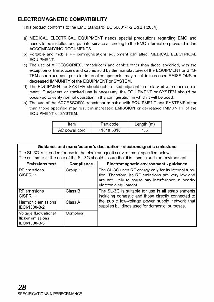
ELECTROMAGNETIC COMPATIBILITYThis product conforms to the EMC Standard(IEC 60601-1-2 Ed.2.1:2004).
a) MEDICAL ELECTRICAL EQUIPMENT needs special precautions regarding EMC andneeds to be installed and put into service according to the EMC information provided in theACCOMPANYING DOCUMENTS.
b) Portable and mobile RF communications equipment can affect MEDICAL ELECTRICALEQUIPMENT.
c) The use of ACCESSORIES, transducers and cables other than those specified, with theexception of transducers and cables sold by the manufacturer of the EQUIPMENT or SYS-TEM as replacement parts for internal components, may result in increased EMISSIONS ordecreased IMMUNITY of the EQUIPMENT or SYSTEM.
d) The EQUIPMENT or SYSTEM should not be used adjacent to or stacked with other equip-ment. IF adjacent or stacked use is necessary, the EQUIPMENT or SYSTEM should beobserved to verify normal operation in the configuration in which it will be used.
e) The use of the ACCESSORY, transducer or cable with EQUIPMENT and SYSTEMS otherthan those specified may result in increased EMISSION or decreased IMMUNITY of theEQUIPMENT or SYSTEM.
Item Part code Length (m)AC power cord 41840 5010 1.5
Guidance and manufacturer's declaration - electromagnetic emissionsThe SL-3G is intended for use in the electromagnetic environment specified below.The customer or the user of the SL-3G should assure that it is used in such an environment.
Emissions test Compliance Electromagnetic environment - guidanceRF emissionsCISPR 11
Group 1 The SL-3G uses RF energy only for its internal func-tion. Therefore, its RF emissions are very low andare not likely to cause any interference in nearbyelectronic equipment.
RF emissionsCISPR 11
Class B The SL-3G is suitable for use in all establishmentsincluding domestic and those directly connected tothe public low-voltage power supply network thatsupplies buildings used for domestic purposes.
Harmonic emissionsIEC61000-3-2
Class A
Voltage fluctuations/flicker emissionsIEC61000-3-3
Complies
28SPECIFICATIONS & PERFORMANCE

Guidance and manufacturer's declaration - electromagnetic immunityThe SL-3G is intended for use in the electromagnetic environment specified below.The customer or the user of the SL-3G should assure that it is used in such an environment.
Immunity test IEC 60601test level
Compliance level
Electromagnetic environment - guidance
Electrostaticdischarge (ESD)IEC 61000-4-2
±6 kV contact
±8 kV air
±6 kV contact
±8 kV air
Floors should be wood, concrete orceramic tile. If floors are covered withsynthetic material, the relative humid-ity should be at least 30%.
Electrical fasttransient/burstIEC 61000-4-4
±2 kV for powersupply lines
±1 kV forinput/output lines
±2 kV for powersupply lines
±1 kV forinput/output lines
Main power supply quality should bethat of a typical commercial or hospi-tal environment.
SurgeIEC 61000-4-5
±1 kVline(s) to line(s)
±2 kVline(s) to earth
±1 kVline(s) to line(s)
±2 kVline(s) to earth
Main power supply quality should bethat of a typical commercial or hospi-tal environment.
Voltage dips, shortinterruptions andvoltage variationson power supplyinput linesIEC 61000-4-11
<5% Ut(>95% dip in Ut)for 0.5 cycle
40% Ut(60% dip in Ut)for 5 cycles
70% Ut(30% dip in Ut)for 25 cycles
<5% Ut(>95% dip in Ut)for 5 sec
<5% Ut(>95% dip in Ut)for 0.5 cycle
40% Ut(60% dip in Ut)for 5 cycles
70% Ut(30% dip in Ut)for 25 cycles
<5% Ut(>95% dip in Ut)for 5 sec
Main power supply quality should bethat of a typical commercial or hospi-tal environment. If the user or the SL-3G requires continued operation dur-ing main power interruptions, it is rec-ommended that the SL-3G bepowered from an uninterruptiblepower supply or battery backup.
Power frequency(50/60 Hz)magnetic fieldIEC 61000-4-8
3 A/m 3 A/m Power frequency magnetic fieldsshould be at levels characteristic of atypical location in a typical commer-cial or hospital environment.
NOTE Ut is the a.c. main voltage prior to application of the test level.
29SPECIFICATIONS & PERFORMANCE

Guidance and manufacturer's declaration - electromagnetic immunityThe SL-3G is intended for use in the electromagnetic environment specified below.The customer or the user of the SL-3G should assure that it is used in such an environment.Immunity test IEC 60601
test levelCompliance
levelElectromagnetic environment-
guidance
Conducted RFIEC 61000-4-6
Radiated RFIEC 61000-4-3
3 Vrms150kHz to 80MHz
3 V/m80MHz to 2.5GHz
3 V
3 V/m
Portable and mobile RF communicationsequipment should be used no closer to anypart of the SL-3G, including cables, thanthe recommended separation distance cal-culated from the equation applicable to thefrequency of the transmitter.
Recommended separation distance
where P is the maximum output power rat-ing of the transmitter in watts (W) accord-ing to the transmitter manufacturer and dis the recommended separation distancein meters (m).
Field strengths from fixed RF transmitters,as determined by an electromagnetic sitesurvey, a should be less than the compli-ance level in each frequency range. b
Interference may occur in the vicinity ofequipment marked with the following sym-bol:
NOTE 1 At 80 MHz and 800 MHz, the higher frequency range applies.NOTE 2 These guidelines may not apply in all situations. Electromagnetic propagation is
affected by absorption and reflection from structures, objects and people.a Field strengths from fixed transmitters, such as base stations for radio (cellular/cordless) tele-
phones and land mobile radios, amateur radio, AM and FM radio broadcast and TV broadcastcannot be predicted theoretically with accuracy. To assess the electromagnetic environmentdue to fixed RF transmitters, an electromagnetic site survey should be considered. If the mea-sured field strength in the location in which the SL-3G is used exceeds the applicable RF com-pliance level above, the SL-3G should be observed to verify normal operation. If abnormalperformance is observed, additional measures may be necessary, such as reorienting or relo-cating the SL-3G.
b Over the frequency range 150 kHz to 80 MHz, field strengths should be less than 3 V/m.
d 1.2 P=
d 1.2 P= 80MHz to 800MHz
d 2.3 P= 80MHz to 2.5GHz
30SPECIFICATIONS & PERFORMANCE
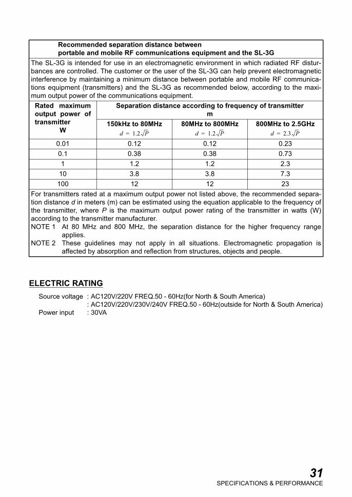
ELECTRIC RATINGSource voltage : AC120V/220V FREQ.50 - 60Hz(for North & South America)
: AC120V/220V/230V/240V FREQ.50 - 60Hz(outside for North & South America)Power input : 30VA
Recommended separation distance betweenportable and mobile RF communications equipment and the SL-3G
The SL-3G is intended for use in an electromagnetic environment in which radiated RF distur-bances are controlled. The customer or the user of the SL-3G can help prevent electromagneticinterference by maintaining a minimum distance between portable and mobile RF communica-tions equipment (transmitters) and the SL-3G as recommended below, according to the maxi-mum output power of the communications equipment.
Rated maximumoutput power oftransmitter
W
Separation distance according to frequency of transmitterm
150kHz to 80MHz 80MHz to 800MHz 800MHz to 2.5GHz
0.01 0.12 0.12 0.230.1 0.38 0.38 0.731 1.2 1.2 2.3
10 3.8 3.8 7.3100 12 12 23
For transmitters rated at a maximum output power not listed above, the recommended separa-tion distance d in meters (m) can be estimated using the equation applicable to the frequency ofthe transmitter, where P is the maximum output power rating of the transmitter in watts (W)according to the transmitter manufacturer.NOTE 1 At 80 MHz and 800 MHz, the separation distance for the higher frequency range
applies.NOTE 2 These guidelines may not apply in all situations. Electromagnetic propagation is
affected by absorption and reflection from structures, objects and people.
d 1.2 P= d 1.2 P= d 2.3 P=
31SPECIFICATIONS & PERFORMANCE
SYSTEM CLASSIFICATIONType of protection against electric shocks: Class I equipment
Class I equipment does not depend on basic insulation only for protection against electricshocks. It can also be grounded; therefore, the metal parts with which one comes into contactdo not become conductive if the basic insulation fails.
Degree of protection against electric shocks: Type B applied partType B applied part is the applied part complying with the specified requirements of the Stan-dard IEC 60601-1 to provide protection against electric shock, particularly regarding allowableLEAKAGE CURRENT.
Degree of protection against harmful ingress of water: IPX0SL-3G has no protection against ingress of water. (The degree of protection against harmfulingress of water defined in IEC 60529 is IPX0)
Classification according to the methods of sterilization or disinfection recom-mended by the manufacturer: not applicable.
SL-3G has no part to be sterilized or be disinfected.
Not AP or APG equipmentClassification according to the degree of safety of application in the presence of aflammable anaesthetic mixture with air or with oxygen or nitrous oxide: Equipmentnot suitable for use in the presence of a flammable anaesthetic mixture with air orwith oxygen or nitrous oxide.
SL-3G should be used in environments where no flammable anesthetics and/or flammablegases are presents.
Classification according to the mode of operation: Continuous operation.Continuous operation is the operation under normal load for an unlimited period, without thespecified limits of temperature being exceeded.
DIMENSIONS AND WEIGHT
PURPOSE OF USEThis instrument is used for the magnified observation of the eye and its various structures bythe eye care professional.
OPERATION PRINCIPLEIlluminates the observed part by the illumination light emitted from the illumination optical sys-tem and allows magnified observation by binocular stereoscopic microscope.
Dimensions 550mm (W) × 430mm (D) × 770 - 800 (H)440mm (W) × 410mm (D) × 770 - 800 (H) (Unit type)
Weight 21kg, 20kg (Unit type)
32SPECIFICATIONS & PERFORMANCE
MAINTENANCE AND CHECKUPS
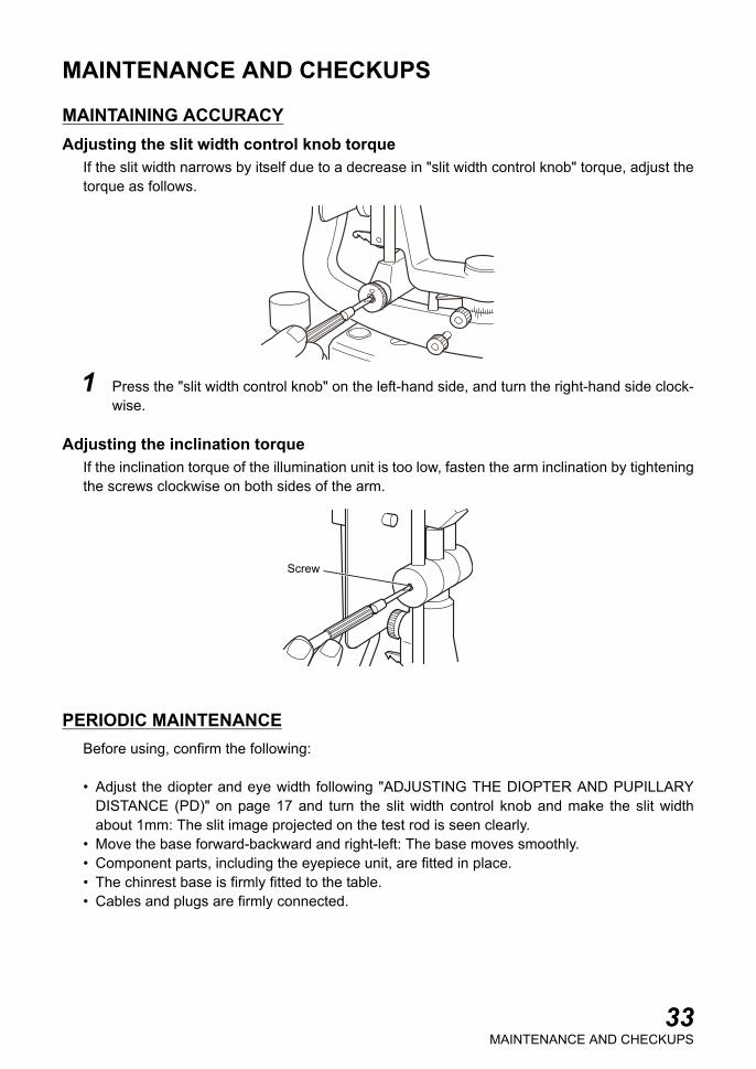
MAINTAINING ACCURACYAdjusting the slit width control knob torque
If the slit width narrows by itself due to a decrease in "slit width control knob" torque, adjust thetorque as follows.
1 Press the "slit width control knob" on the left-hand side, and turn the right-hand side clock-wise.
Adjusting the inclination torqueIf the inclination torque of the illumination unit is too low, fasten the arm inclination by tighteningthe screws clockwise on both sides of the arm.
PERIODIC MAINTENANCEBefore using, confirm the following:
• Adjust the diopter and eye width following "ADJUSTING THE DIOPTER AND PUPILLARYDISTANCE (PD)" on page 17 and turn the slit width control knob and make the slit widthabout 1mm: The slit image projected on the test rod is seen clearly.
• Move the base forward-backward and right-left: The base moves smoothly.• Component parts, including the eyepiece unit, are fitted in place.• The chinrest base is firmly fitted to the table.• Cables and plugs are firmly connected.
Screw
33MAINTENANCE AND CHECKUPS
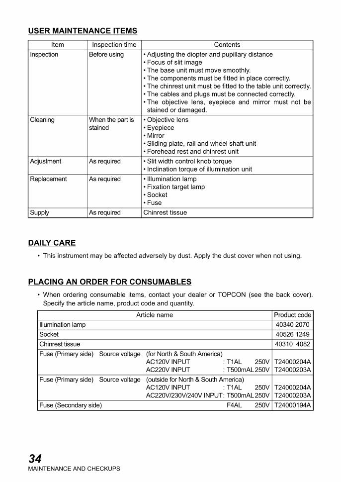
USER MAINTENANCE ITEMS
DAILY CARE• This instrument may be affected adversely by dust. Apply the dust cover when not using.
PLACING AN ORDER FOR CONSUMABLES• When ordering consumable items, contact your dealer or TOPCON (see the back cover).
Specify the article name, product code and quantity.
Item Inspection time ContentsInspection Before using • Adjusting the diopter and pupillary distance
• Focus of slit image• The base unit must move smoothly.• The components must be fitted in place correctly.• The chinrest unit must be fitted to the table unit correctly.• The cables and plugs must be connected correctly.• The objective lens, eyepiece and mirror must not be
stained or damaged.Cleaning When the part is
stained• Objective lens• Eyepiece• Mirror• Sliding plate, rail and wheel shaft unit• Forehead rest and chinrest unit
Adjustment As required • Slit width control knob torque• Inclination torque of illumination unit
Replacement As required • Illumination lamp• Fixation target lamp• Socket• Fuse
Supply As required Chinrest tissue
Article name Product codeIllumination lamp 40340 2070Socket 40526 1249Chinrest tissue 40310 4082Fuse (Primary side) Source voltage (for North & South America)
AC120V INPUT : T1AL 250VAC220V INPUT : T500mAL250V
T24000204AT24000203A
Fuse (Primary side) Source voltage (outside for North & South America)AC120V INPUT : T1AL 250VAC220V/230V/240V INPUT: T500mAL250V
T24000204AT24000203A
Fuse (Secondary side) F4AL 250V T24000194A
34MAINTENANCE AND CHECKUPS

REPLACING ILLUMINATION LAMPS
1 Turn OFF ( ) the "POWER switch" and removethe cable plug.Pull out the plug from the "lamp house cover". Turnthe "lamp house cover" counterclockwise andremove upward.
2 Lightly pull the "socket fixing lever" and turn in thedirection indicated by the arrow.
3 Pull out the "lamp unit".
4 Remove the "illumination lamp" from the "socket"and fit the new lamp.When fitting the new lamp, make sure the directionof the "illumination lamp" and "socket" is correct.∗ For the article name and product code of the "illu-
mination lamp", refer to "PLACING AN ORDER FOR CONSUMABLES" on P.34.
5 Fit the pin into the groove on the "lamp house cover" as shown below. Turn the lamphouse cover clockwise to fix it.
6 Connect the "plug".
Unless the pin is fitted into the groove correctly, the plug is not connected properly andthe illumination is not turned on.
CAUTION When replacing the lamp, switch off the power supply and remove thepower cord to avoid electric shock.
CAUTION Beware of high temperatures when replacing the lamp immediatelyafter switching it off: these could cause burns.
NOTE To ensure perfect illumination, make sure that the socket flange andnotch are firmly fitted to the lamp house.
NOTEUse a soft cloth and do not touch the illumination lamp with bare fin-gers: fingerprints and stains may affect illumination and cause prema-ture failure of the lamp.
Lamp house coverPlug
Socket fixing
Lamp unit
lever
Pin
35MAINTENANCE AND CHECKUPS
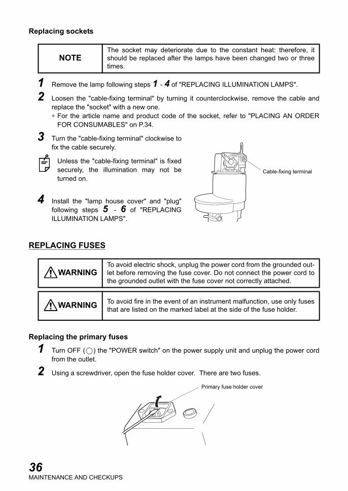
Replacing sockets
1 Remove the lamp following steps 1 - 4 of "REPLACING ILLUMINATION LAMPS".
2 Loosen the "cable-fixing terminal" by turning it counterclockwise, remove the cable andreplace the "socket" with a new one.∗ For the article name and product code of the socket, refer to "PLACING AN ORDER
FOR CONSUMABLES" on P.34.
3 Turn the "cable-fixing terminal" clockwise tofix the cable securely.
Unless the "cable-fixing terminal" is fixedsecurely, the illumination may not beturned on.
4 Install the "lamp house cover" and "plug"following steps 5 - 6 of "REPLACINGILLUMINATION LAMPS".
REPLACING FUSES
Replacing the primary fuses
1 Turn OFF ( ) the "POWER switch" on the power supply unit and unplug the power cordfrom the outlet.
2 Using a screwdriver, open the fuse holder cover. There are two fuses.
NOTEThe socket may deteriorate due to the constant heat: therefore, itshould be replaced after the lamps have been changed two or threetimes.
WARNINGTo avoid electric shock, unplug the power cord from the grounded out-let before removing the fuse cover. Do not connect the power cord tothe grounded outlet with the fuse cover not correctly attached.
WARNING To avoid fire in the event of an instrument malfunction, use only fusesthat are listed on the marked label at the side of the fuse holder.
Cable-fixing terminal
Primary fuse holder cover
36MAINTENANCE AND CHECKUPS

3 Replace the fuses with ones having the same capacity as the label.
∗ For the article name and product code of the fuse, refer to "PLACING AN ORDER FORCONSUMABLES" on P.34.
4 Close the fuse holder cover.
When the fuses have blown out, the whole instrument does not operate. Replace thefuses.
Replacing the secondary fuses
1 Turn OFF ( ) the "POWER switch" on the power supply unit and unplug the power cordfrom the outlet.
2 Turn the secondary fuse holder cover counterclockwise with a screwdriver. The fuseholder can be removed.
3 Replace the fuse with one having the same capacity as the label.
∗ For the article name and product code of the fuse, refer to "PLACING AN ORDER FORCONSUMABLES" on P.34.
4 While pushing in the fuse holder cover with a screwdriver, turn it clockwise and fix it.
When the fuse has blown out, the whole instrument does not operate. Replace the fuse.
Replacement of fuses
Secondary fuse holder
Replacement of fuse
37MAINTENANCE AND CHECKUPS
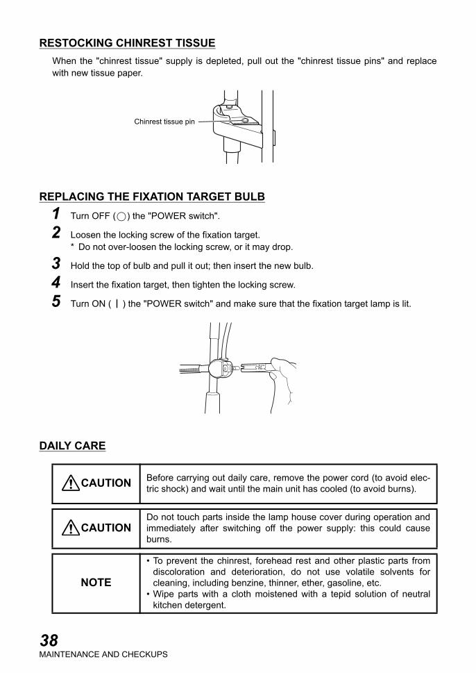
RESTOCKING CHINREST TISSUEWhen the "chinrest tissue" supply is depleted, pull out the "chinrest tissue pins" and replacewith new tissue paper.
REPLACING THE FIXATION TARGET BULB1 Turn OFF ( ) the "POWER switch".
2 Loosen the locking screw of the fixation target.* Do not over-loosen the locking screw, or it may drop.
3 Hold the top of bulb and pull it out; then insert the new bulb.
4 Insert the fixation target, then tighten the locking screw.
5 Turn ON ( ) the "POWER switch" and make sure that the fixation target lamp is lit.
DAILY CARE
CAUTION Before carrying out daily care, remove the power cord (to avoid elec-tric shock) and wait until the main unit has cooled (to avoid burns).
CAUTIONDo not touch parts inside the lamp house cover during operation andimmediately after switching off the power supply: this could causeburns.
NOTE
• To prevent the chinrest, forehead rest and other plastic parts fromdiscoloration and deterioration, do not use volatile solvents forcleaning, including benzine, thinner, ether, gasoline, etc.
• Wipe parts with a cloth moistened with a tepid solution of neutralkitchen detergent.
Chinrest tissue pin
38MAINTENANCE AND CHECKUPS
Cleaning the parts in contact with the patientWhen the forehead rest and chinrest unit are stained:
Prepare a tepid solution of neutral detergent for kitchenware. Moisten the cloth with theaforementioned solution and wring it thoroughly. Then wipe the unit with the cloth.
Cleaning lenses and mirrors
1 Prepare a solution of ethyl alcohol 20% and ether 80%.
2 Remove dust from lens and mirror surfaces with the cleaning brush, or a blower.
3 Using clean gauze or lint-free tissue, lightly clean with a rotating movement from the cen-ter of the lens/mirror outwards.
4 If the stain remains, repeat this 2 to 3 times.
5 If stains are persistent, call your dealer or TOPCON (see the back cover).
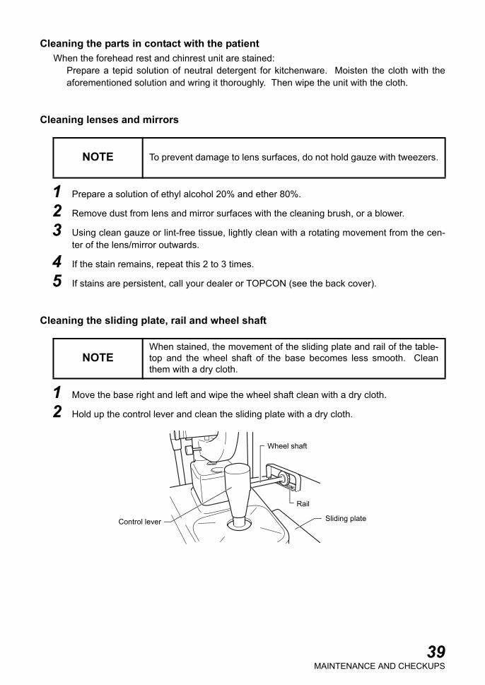
Cleaning the sliding plate, rail and wheel shaft
1 Move the base right and left and wipe the wheel shaft clean with a dry cloth.
2 Hold up the control lever and clean the sliding plate with a dry cloth.
NOTE To prevent damage to lens surfaces, do not hold gauze with tweezers.
NOTEWhen stained, the movement of the sliding plate and rail of the table-top and the wheel shaft of the base becomes less smooth. Cleanthem with a dry cloth.
Rail
Wheel shaft
Sliding plateControl lever
39MAINTENANCE AND CHECKUPS
OPTIONAL ACCESSORIES
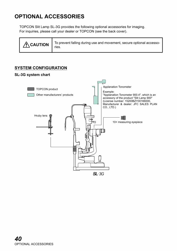
TOPCON Slit Lamp SL-3G provides the following optional accessories for imaging.For inquiries, please call your dealer or TOPCON (see the back cover).
SYSTEM CONFIGURATIONSL-3G system chart
CAUTION To prevent falling during use and movement, secure optional accesso-ries.
TOPCON product
Other manufacturers’ products
Hruby lens
Applanation Tonometer
10× measuring eyepiece
Example:"Applanation Tonometer 900.4", which is an accessory of the product "Slit Lamp 900" (License number: 15200BZY00166000, Manufacturer & dealer: JFC SALES PLANCO., LTD.)
40OPTIONAL ACCESSORIES

10× MEASURING EYEPIECEFeatures
Can measure dimensions and angles (by replacing thenormal eyepiece).
HRUBY LENSFeatures
Normally, observation can be carried out only as far asthe vitreous body of the anterior segment, due to therefracting power of the cornea and lens. With the Hrubylens, the posterior vitreous body and fundus can also beobserved.
41OPTIONAL ACCESSORIES

42REFERENCE MATERIAL
REFERENCE MATERIAL
SHAPE OF PLUG
SYMBOL
ADJUSTABLE AUTOMATIC INSTRUMENT TABLEAutomatic instrument table AIT-16
Specifications• Table size 490 (D) × 500 (W) mm
665 - 885 (H) mm• Weight approx. 25kg
Country Voltage/frequency Shape of plugMexico 110V/50Hz Type C&EArgentina 220V/60Hz Type APeru 220V/60Hz Type AVenezuela 110V/50Hz Type C&E
Bolivia & Paraguay 220V/60Hz Type A (Most common)Type H (Infrequently)
Chile 220V/60Hz Type AColombia 110V/50Hz Type C
Brazil 220V/60Hz127V/60Hz
Type AType C
Ecuador 110V/50Hz Type C&EUSA 120V/60Hz Type A (Hospital Grade)Canada 120V/60Hz Type A (Hospital Grade)
Symbol IEC Publication Description Description (French)
60417-5032 Alternating Current Courant alternatif
60417-5008 Off (power: disconnection fromthe main power supply)
Éteint (courant: coupure avecle secteur)
60417-5007 On (power: connected to themain power supply)
Allumé (courant: raccorde-ment sur le secteur)
60878-02-02 Type B applied part Partie appliquée du Type B
60348 Attention, consult accompany-ing documents
Attention, consulter les docu-ments d'accompagnement
43RELATION BETWEEN SETTING OF ILLUMINATION LEVEL AND MAXIMUM RADIANCE
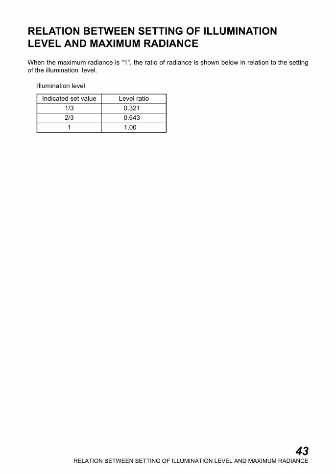
RELATION BETWEEN SETTING OF ILLUMINATIONLEVEL AND MAXIMUM RADIANCEWhen the maximum radiance is "1", the ratio of radiance is shown below in relation to the settingof the illumination level.
Illumination level
Indicated set value Level ratio1/3 0.3212/3 0.6431 1.00

44INFORMATION ABOUT THE OPTICAL RADIATION HAZARD TO THE USER
INFORMATION ABOUT THE OPTICAL RADIATION HAZARD TO THE USER
Light distribution of illumination
CAUTIONThe light emitted from this instrument is potentially hazardous. Thelonger the duration of exposure, the greater the risk of ocular damage.Exposure to light from this instrument when operated at maximumintensity will exceed the safety guideline after 65 sec.
SL-3G : Illumination spectral distribution
0
0.1
0.2
0.3
0.4
0.5
0.6
0.7
0.8
0.9
1
300 400 500 600 700 800 900 1000 1100
Wave length [nm]
Rela
tive inte
nsity
Please provide the following information when contacting us regarding questions about thisinstrument:• Model name : SL-3G• Serial No. : This is described on the rating nameplate.• Period of use : Please inform us of the date of purchase.• State of instrument : Please provide us with as much detail as possible on the problem.
SLIT LAMP SL-3G
INSTRUCTION MANUALVersion of 2008 (2008.12-100TH )Date of issue: December 10, 2008
Published by TOPCON CORPORATION
75-1 Hasunuma-cho, Itabashi-ku, Tokyo, 174-8580 Japan.
©2008 TOPCON CORPORATION ALL RIGHTS RESERVED
1

SLIT LAMP
SL-3G
44637 95991Printed in Japan 0812-30TH 1