instruction manual perimeter octopus 600 · the user and patient. ... en 60601‑1 standard. note!...
TRANSCRIPT

1© HAAG‑STREIT AG, 3098 Koeniz, Switzerland ‑ HS Doc. no. 1500.7220367.04020 – 2. edition / 2013 – 09
DEUTSCH ENGLISHFRANÇAISITALIANOESPAÑOLNEDERLANDS PORTUGUÊSSVENSKA
DOC. no. 1500 1500.1400209.04000
INSTRUCTION MANUALPerimeter
OCTOPUS® 6002. edition / 2013 – 09
01-IFU_Octopus600-7220367_04020_eng.indd 1 23.09.2013 08:03:11

2 © HAAG‑STREIT AG, 3098 Koeniz, Switzerland ‑ HS Doc. no. 1500.7220367.04020 – 2. edition / 2013 – 09
DEUTSCHENGLISH FRANÇAIS ITALIANO ESPAÑOL NEDERLANDSPORTUGUÊS SVENSKA
INSTRUCTION MANUALPerimeter
OCTOPUS® 6002. edition / 2013 – 09
Introduction Thank you for choosing a HAAG‑STREIT appliance. Provided you comply carefully with the regulations in this instruction manual, we can guarantee the reliable and unproblematic use of our product.
Purpose of use The Octopus 600 perimeter is designed for the examination, analysis and documen‑tation of the field of sight, especially the light difference sensitivity and other func‑tions of the human eye.
ContraindicationWARNING!Certain light stimuli with a high contrast and certain frequencies as pre‑sented in the Octopus 600 with the pulsar method can trigger episodes of photosensitive epilepsy or consciousness disturbances in isolated cases. This can also occur in patients who have not previously dis‑played any signs of epilepsy or similar conditions. Should the patient feel unwell during the examination or if there is any indication of a con‑sciousness disturbance, the examination must be interrupted immedi‑ately. A standard white/white (SAP) examination can be performed as an alternative.
WARNING!Read the instructions for use carefully before commissioning the Octo‑pus 600. They contain important information concerning the safety of the user and patient.
NOTE!Federal law restricts this device to sale by or on the order of a physici‑an or practitioner.
01-IFU_Octopus600-7220367_04020_eng.indd 2 23.09.2013 08:03:11

3© HAAG‑STREIT AG, 3098 Koeniz, Switzerland ‑ HS Doc. no. 1500.7220367.04020 – 2. edition / 2013 – 09
DEUTSCH ENGLISHFRANÇAISITALIANOESPAÑOLNEDERLANDS PORTUGUÊSSVENSKA
Contents
1. Safety ................................................................................... 41.1 Areas of application of the device ...........................................................................41.2 Patient population ...................................................................................................41.3 Ambient conditions ..................................................................................................41.4 Shipment and unpacking ........................................................................................41.5 Installation warnings ..............................................................................................41.6 Operation and environment ....................................................................................51.7 Disinfection .............................................................................................................51.8 Warranty and product liability ..................................................................................51.9 Symbols ..................................................................................................................6
2. Introduction .......................................................................... 62.1 Device description ...................................................................................................62.2 System components ...............................................................................................62.3 Device overview ......................................................................................................62.4 User interface (14) ..................................................................................................72.5 Housing ...................................................................................................................72.6 Forehead rest ..........................................................................................................72.7 Near correction lens ................................................................................................72.8 Patient‑side cover ..................................................................................................72.9 Corrective lenses ....................................................................................................72.10 Connections ............................................................................................................82.10.1 USB ports ................................................................................................................82.10.2 Mains connection ....................................................................................................82.10.3 Ethernet port ...........................................................................................................82.11 LED background lighting .........................................................................................82.12 Fixation control ........................................................................................................82.13 Examination data ....................................................................................................8
3. Appliance assembly / installation ...................................... 83.1 Transporting the appliance ......................................................................................83.2 Connecting the patient response button .................................................................83.3 Connecting the electric power supply cable ............................................................9
4. Safesystemconfigurationinaccordance with EN 60601-1 ................................................................. 104.1 System versions, OCTOPUS 600 with printer ......................................................10
5. Commissioning ...................................................................115.1 Switching on the appliance ...................................................................................115.2 Switching off the appliance ...................................................................................11
6. Operation .............................................................................116.1 Setting up the patient ...........................................................................................11
7. Software/Helpmenu/Errormessages ...........................118. Technical data .....................................................................118.1 OCTOPUS 600 .....................................................................................................118.2 Infrared illumination ...............................................................................................118.3 Dimensions ...........................................................................................................128.4 Field of sight .........................................................................................................12
9. Maintenance ....................................................................... 129.1 Repairs ..................................................................................................................129.2 Cleaning ................................................................................................................129.3 Applied parts .........................................................................................................12
A. Appendix ............................................................................ 12A.1 Accessories / spare parts ......................................................................................12
B. Legalregulations ............................................................... 13C. Classification ..................................................................... 13D. Disposal .............................................................................. 13E. Standards ........................................................................... 13F. RoHS China ........................................................................ 13F.1 RoHS declaration ..................................................................................................14
G. Information and manufacturer's declaration concerningelectromagneticcompatibility (EMC) .................................................................................. 14G.1 General .................................................................................................................14G.2 Table 1: Emitted interference ................................................................................14G.3 Table 2: Immunity ..................................................................................................15G.4 Table 3: Immunity (not life‑support equipment) .....................................................16G.5 Table 4: Recommended safe distances (not life‑support equipment) ...................17
01-IFU_Octopus600-7220367_04020_eng.indd 3 23.09.2013 08:03:11

4 © HAAG‑STREIT AG, 3098 Koeniz, Switzerland ‑ HS Doc. no. 1500.7220367.04020 – 2. edition / 2013 – 09
DEUTSCHENGLISH FRANÇAIS ITALIANO ESPAÑOL NEDERLANDSPORTUGUÊS SVENSKA
1. Safety FORBIDDEN!Failure to comply with the instructions can result in material damage and pose a danger to users and patients.
WARNING!These warnings must absolutely be complied with to guarantee safe operation of the device and to avoid any danger to users and to patients.
NOTE!Important information: please read carefully.
1.1 Areas of application of the deviceThe users are ophthalmologists, optometrists, opticians, orthoptists or other trained specialists. The examination is performed in slightly darkened examination rooms.
1.2 Patient populationThe patient must be capable of sitting up straight and keeping his head still. He/she must be physically and mentally able to cooperate well and is mentally capable of following the examination. Patients must be at least 6 years old.
1.3 Ambient conditionsTransport: Temperature
Air pressureRelative humidity
fromfromfrom
‑40 °C500 hPa10%
tototo
+70 °C1060 hPa95%
Storage: TemperatureAir pressureRelative humidity
fromfromfrom
‑10 °C700 hPa 10%
tototo
+55 °C1060 hPa95%
Use: TemperatureAir pressureRelative humidity
fromfromfrom
+10 °C800 hPa 30%
tototo
+35 °C1060 hPa90%
Application height < 2,000 m above sea level
1.4 Shipmentandunpacking• Before you unpack the appliance, check whether the packaging shows traces of
incorrect handling or damage. If this is the case, notify the transport company that has delivered the goods to you. Unpack the equipment together with a represent‑ative of the transport company. Make a report of any damaged parts. This report must be signed by you and by the representative of the transport company.
• Leave the device in the packaging for a few hours before unpacking it (conden‑sation).
• Check the appliance for damage after it is unpacked. Return defective applianc‑es in the appropriate packaging.
• Store packaging material carefully, so that it can be used for possible returns or when moving.
1.5 InstallationwarningsFORBIDDEN!Never use the device in potentially explosive environments where vol‑atile solvents (alcohol, benzine, etc.) and combustible anaesthetics are in use.
WARNING! • Installation, repairs and modifications may only be performed by trained specialists.
• Any third‑party device must be connected in compliance with the IEC/EN 60601‑1 standard.
NOTE! • The device must be set up in a medical room in such a way that no direct light falls on it from the side or patient's side.
• The use of accessories other than than those listed may result in higher emissions or lower interference immunity of the Octopus 600.
• The software must be installed by trained personnel.
01-IFU_Octopus600-7220367_04020_eng.indd 4 23.09.2013 08:03:11

5© HAAG‑STREIT AG, 3098 Koeniz, Switzerland ‑ HS Doc. no. 1500.7220367.04020 – 2. edition / 2013 – 09
DEUTSCH ENGLISHFRANÇAISITALIANOESPAÑOLNEDERLANDS PORTUGUÊSSVENSKA
1.6 Operation and environmentWARNING! • To avoid the risk of suffering an electric shock, this device may only be connected up to the mains with a ground connection.
• The plug, cable and ground connection of the socket must be func‑tioning perfectly.
• Make sure that the appliance is only connected to power supplies as defined on the type plate. The appliance must be disconnected from the mains by pulling out the plug before any maintenance and clean‑ing work is performed.
• Computers and further ancillary devices (printers, etc.) must comply with the EN 60601‑1 standard or be connected through galvanic iso‑lation to external networks (safety isolating transformer).
WARNING! • The doctor or the operator is obliged to inform the patient about the safety instructions concerning him and to ensure that these instruc‑tions are complied with.
• The examination of the patient, the use of the device and the inter‑pretation of the results may only be conducted by trained and experi‑enced individuals.
• Turning off the eye monitoring functions is not recommended. In all other cases, the user must monitor the eye personally during the examination.
• All users must be appropriately trained and familiarised with the contents of the instructions for use, especially in regard to the safety information contained therein.
NOTE! • This appliance must only be operated by qualified and trained per‑sonnel. The owner is responsible for their training.
• This appliance may only be used for the purpose described in these instructions for use.
• The device must be set up in a medical room in such a way that no direct light falls on it from the side or patient's side.
NOTE! • Keep these instructions for use in a place where they are accessible to those working with the device at all times. Warranty claims can only be made if the instructions in these instructions for use are complied with.
• Always remove the dust cover before switching the appliance on. The device may otherwise become damaged due to overheating. Like‑wise, make sure that the appliance is switched off before attaching the dust cover.
• Only original spare parts and original accessories may be used for repairs. The use of accessories other than than those listed may result in higher emissions or lower interference immunity of the Oc‑topus 600.
• Turn the device off if it will not be used for an extended period of time.
1.7 DisinfectionNOTE!The device does not need to be disinfected.
For more information on cleaning, please refer to the 'Maintenance' section.
1.8 Warranty and product liability• The product should be treated as described in the “Safety” chapter. Improper
handling can damage the product. This would void all guarantee claims.• Continued use of a product damaged by incorrect handling may lead to personal
injury. In this case, the manufacturer accepts no liability.
01-IFU_Octopus600-7220367_04020_eng.indd 5 23.09.2013 08:03:11

6 © HAAG‑STREIT AG, 3098 Koeniz, Switzerland ‑ HS Doc. no. 1500.7220367.04020 – 2. edition / 2013 – 09
DEUTSCHENGLISH FRANÇAIS ITALIANO ESPAÑOL NEDERLANDSPORTUGUÊS SVENSKA
1.9 SymbolsRead the instructions for use attentively
General warning: Read the ac‑companying documentation
Product classification type B. Device includes type B appli‑cation parts, namely patient response button
Disposal instructions.See 'Disposal' section.
12 RoHS China Test symbol of CSA with approval for USA
European certificate of con‑formity
Ground connection
Year of production Manufacturer
2. Introduction2.1 Device description• The Octopus 600 is a binocular screen perimeter for examining the central field
of sight (30°). The device can be employed autonomously, i.e., the examination and control components are integrated in the device.
• Integrated, automatic fixation monitoring increases the reliability of the examina‑tion results.
• The Octopus 600 is employed by clinical users and for research purposes. • New operating system software and perimetry software can be downloaded and
updated by visiting www.HAAG‑STREIT.com.
2.2 System componentsThe Octopus 600 comprises the following components:• Octopus 600• Patient response button• Keyboard/mouse (optional)
2.3 Device overviewOverview of patient side1. Upper part of housing 2. Right shell3. Capacitive button for operating the forehead rest 4. Left shell 5. Forehead rest with integrated sensor for detecting the head position6. Infrared eye illumination 7. Near correction lens +3.25 dpt 8. Patient‑side cover 9. Corrective lenses 10. Corrective lens compartment11. Automatically closing cover12. Patient response button 13. Patient response button connection
12345678910111213
01-IFU_Octopus600-7220367_04020_eng.indd 6 23.09.2013 08:03:12
7© HAAG‑STREIT AG, 3098 Koeniz, Switzerland ‑ HS Doc. no. 1500.7220367.04020 – 2. edition / 2013 – 09
DEUTSCH ENGLISHFRANÇAISITALIANOESPAÑOLNEDERLANDS PORTUGUÊSSVENSKA
2.6 Forehead restA wide, ergonomically designed forehead rest (5) allows the patient to maintain a comfortable posture during the examination. The forehead rest can be moved for‑wards and backwards by pressing the triangular buttons (a).
(a)
2.7 Near correction lensThe near correction lenses (7) integrated in the device also make it possible to ac‑commodate older patients on the examination screen.
2.8 Patient-side cover The cover on the patient side (8) can be equipped with two corrective lenses. The magnetic holder on the corrective lenses allows simple, quick positioning.
2.9 Corrective lensesPatients' ametropia can be corrected with the supplied corrective lenses. A correc‑tive lens set is composed of 12 spherical corrective lenses (9) from –8 dpt to +4 dpt.
NOTE! • In cases of cylindrical ametropia > 1 dpt, we recommend that patients wear their own glasses or contact lenses for the examination insofar as this is possible and the field of sight is not restricted.
• To protect the lenses from soiling and damage, they should be put back in the compartment provided for them.
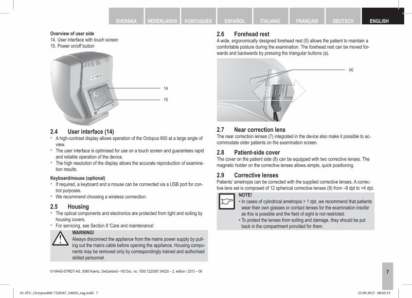
Overview of user side14. User interface with touch screen15. Power on/off button
14
15
2.4 User interface (14)• A high‑contrast display allows operation of the Octopus 600 at a large angle of
view. • The user interface is optimised for use on a touch screen and guarantees rapid
and reliable operation of the device.• The high resolution of the display allows the accurate reproduction of examina‑
tion results.Keyboard/mouse (optional)• If required, a keyboard and a mouse can be connected via a USB port for con‑
trol purposes.• We recommend choosing a wireless connection.
2.5 Housing• The optical components and electronics are protected from light and soiling by
housing covers.• For servicing, see Section 8 'Care and maintenance'.
WARNING!Always disconnect the appliance from the mains power supply by pull‑ing out the mains cable before opening the appliance. Housing compo‑nents may be removed only by correspondingly trained and authorised skilled personnel.
01-IFU_Octopus600-7220367_04020_eng.indd 7 23.09.2013 08:03:15

8 © HAAG‑STREIT AG, 3098 Koeniz, Switzerland ‑ HS Doc. no. 1500.7220367.04020 – 2. edition / 2013 – 09
DEUTSCHENGLISH FRANÇAIS ITALIANO ESPAÑOL NEDERLANDSPORTUGUÊS SVENSKA
2.10 Connections16. 4 x USB 2.0 port17. Mains switch18. Fuse holder with two fuses 3.15 AH / 250 V19. Mains connection20. Ethernet port
16
17
18
19
20
2.10.1 USB portsThere are a total of 4 USB 2.0 ports (16) available. They can be used to connect USB components such as keyboards, mice, USB sticks, USB hard disks or printers.
WARNING!This connection is not galvanically isolated. Devices such as printers can only be connected via USB if they are equipped with a safety iso‑lating transformer as per EN 60601‑1 or operated with a medically ap‑proved power supply.
2.10.2 Mains connectionThe power cable must correspond to the nationally applicable safety requirements.
2.10.3 Ethernet portThere is an Ethernet port on the side of the device. Always use a shielded cable of category 5e permitting transmissions of up to 1 GHz without interference. This Eth‑ernet port is electrically isolated and has a dielectric strength of 4 kV according to EN 60601‑1.
2.11 LEDbackgroundlightingIn the Octopus 600, LEDs are used as light sources for the periphery and stimu‑lus. The light intensity of the background lighting is measured with two independ‑ent light sensors and adjusted to the preset nominal values each time the perimeter is switched on. These nominal values are defined in the factory by HAAG‑STRE‑IT. The LED background lighting of the examination display is set via an adjustable power source. The intensity of the display can also be varied via grey stages.
2.12 Fixation controlThe examined eye of the patient is illuminated with infrared LEDs (6), photographed by a CMOS camera and displayed on the user monitor. The built‑in automatic fix‑ation control function increases the reliability of the examination results. Precise positioning of the examined eye is performed by motorised fine adjustment of the forehead rest (5).
2.13 Examination dataThe examination data are stored on the integrated solid‑state drive (SSD) or in an external database via the Ethernet port. It is also possible to export the examination data to a USB storage device via a USB port.
3. Appliance assembly / installation3.1 Transportingtheappliance• Transport the appliance over larger distances in its origi‑
nal packaging. • For short distances, grasp the device with two hands
holding the side shells on the left and right and lift it.
3.2 ConnectingthepatientresponsebuttonThe connection socket for the patient response button is below the holder. The re‑taining bar on the connection plug is oriented towards the patient side.
FORBIDDEN!Apart from the patient response button, no other cables may be con‑nected to the RJ12 socket
01-IFU_Octopus600-7220367_04020_eng.indd 8 23.09.2013 08:03:15
9© HAAG‑STREIT AG, 3098 Koeniz, Switzerland ‑ HS Doc. no. 1500.7220367.04020 – 2. edition / 2013 – 09
DEUTSCH ENGLISHFRANÇAISITALIANOESPAÑOLNEDERLANDS PORTUGUÊSSVENSKA
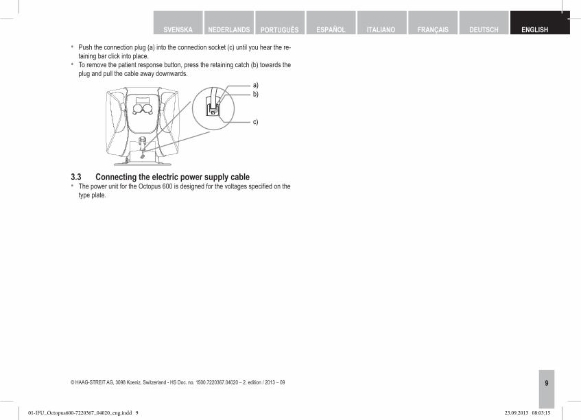
• Push the connection plug (a) into the connection socket (c) until you hear the re‑taining bar click into place.
• To remove the patient response button, press the retaining catch (b) towards the plug and pull the cable away downwards.
b)a)
c)
3.3 Connectingtheelectricpowersupplycable• The power unit for the Octopus 600 is designed for the voltages specified on the
type plate.
01-IFU_Octopus600-7220367_04020_eng.indd 9 23.09.2013 08:03:15
10 © HAAG‑STREIT AG, 3098 Koeniz, Switzerland ‑ HS Doc. no. 1500.7220367.04020 – 2. edition / 2013 – 09
DEUTSCHENGLISH FRANÇAIS ITALIANO ESPAÑOL NEDERLANDSPORTUGUÊS SVENSKA
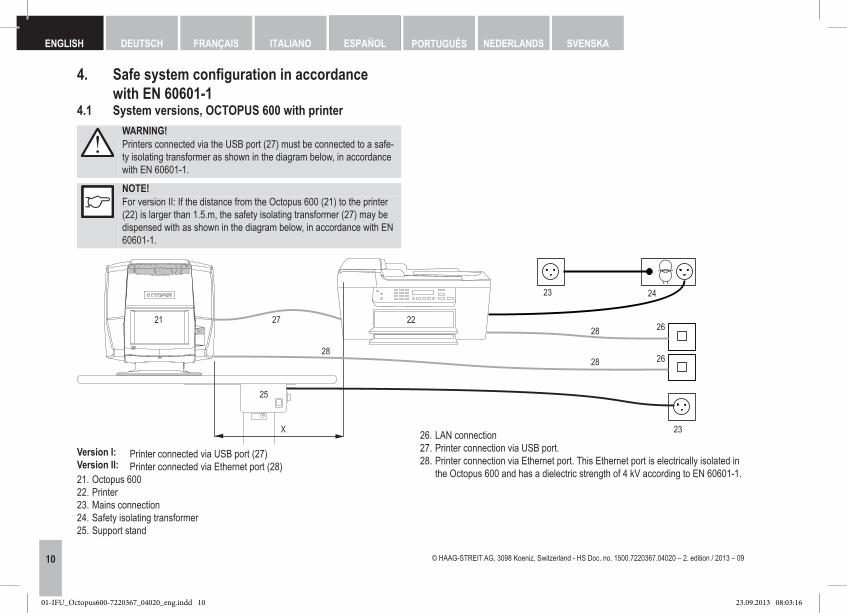
4. Safesystemconfigurationinaccordance with EN 60601-14.1 System versions, OCTOPUS 600 with printer
WARNING!Printers connected via the USB port (27) must be connected to a safe‑ty isolating transformer as shown in the diagram below, in accordance with EN 60601‑1.
NOTE!For version II: If the distance from the Octopus 600 (21) to the printer (22) is larger than 1.5.m, the safety isolating transformer (27) may be dispensed with as shown in the diagram below, in accordance with EN 60601‑1.
X
21 2228
2828
23 24
26
26
23
27
25
Version I:Version II:
Printer connected via USB port (27)Printer connected via Ethernet port (28)
21. Octopus 60022. Printer23. Mains connection24. Safety isolating transformer25. Support stand
26. LAN connection27. Printer connection via USB port.28. Printer connection via Ethernet port. This Ethernet port is electrically isolated in
the Octopus 600 and has a dielectric strength of 4 kV according to EN 60601‑1.
01-IFU_Octopus600-7220367_04020_eng.indd 10 23.09.2013 08:03:16

11© HAAG‑STREIT AG, 3098 Koeniz, Switzerland ‑ HS Doc. no. 1500.7220367.04020 – 2. edition / 2013 – 09
DEUTSCH ENGLISHFRANÇAISITALIANOESPAÑOLNEDERLANDS PORTUGUÊSSVENSKA
5. Commissioning5.1 SwitchingontheapplianceBefore connecting the Octopus 600 to a suitable power socket, it must be ensured that the mains switch (0/I) (17) is set to OFF (0). The mains switch is on the right of the base of the device viewed from the user's side. Then set the mains switch (0/I) to ON (I). The device is now in standby mode. The device can be switched on with the Power On/Off button (15). The operating system and then the application are started automatically. The device is ready for use after approximately one minute.
5.2 SwitchingofftheapplianceOnce the Power On/Off button (15) is pressed, a confirmation prompt appears. As an alternative to the Power On/Off button, the device can also be switched off via the software menu [File] ‑ [Exit]. After approximately 15 seconds, the LED display on the Power On/Off button goes out and the device enters standby mode.
WARNING!To avoid losing data, always switch the device off with the Power On/Off button (15) first and then the mains switch. The Power On/Off button does not disconnect the device from the pow‑er supply. When servicing, always use the mains switch (17) and dis‑connect the device from the power supply.
NOTE!If the mains switch is still switched on, the device is in standby mode and consumes little power.
6. Operation6.1 Settingupthepatient• The corrective lenses are selected so that the patient sees the fixation mark on
the examination screen clearly. The patient's glasses can be used as an aid for this.
• The patient sits comfortably in front of the device and places his forehead on the forehead rest. The forehead rest can be set to the correct position. The user chooses the eye to be examined (OS or OD). Then the video image for fixation control appears. This is equipped with a rectangle which defines the relevant area of the pupil position.
7. Software/Helpmenu/ErrormessagesThe software's help section contains instructions and help for performing an exam‑ination and descriptions of the error messages. The help can be opened via the F1 key or in the [?] ‑ [Help] menu.
WARNING!The software must be installed by trained personnel in accordance with separate installation instructions. It is strongly recommended to make a backup before running a software update.
8. Technical data8.1 OCTOPUS 600Type designation Octopus 600Mains voltage: 100 – 240 VACPower consumption: 100 VAPower consumption in standby: 3WOperating frequency: 50 / 60 HzFuses: 2 x T 3.15 AH 250 VFunctional principle: Binocular screen perimeterExamination principle: Subjective test using bracketing procedurePatient positioning: Adjustable forehead restFixation control: Permanent video‑based fixation controlEccentricity: 60°Dynamic range: 0 – 35 dB / srcStimulus intensity: 0.015 – 150 cd/m²Stimulus colour: WhiteUSB port: USB 2.0 ‑ StandardEthernet port: 1000 Base‑T (1Gbit)Internal memory SSD: 32 GByte
8.2 Infrared illuminationLight source: LEDWavelength: 940 nmAngle of radiation: ±22°
01-IFU_Octopus600-7220367_04020_eng.indd 11 23.09.2013 08:03:16
12 © HAAG‑STREIT AG, 3098 Koeniz, Switzerland ‑ HS Doc. no. 1500.7220367.04020 – 2. edition / 2013 – 09
DEUTSCHENGLISH FRANÇAIS ITALIANO ESPAÑOL NEDERLANDSPORTUGUÊS SVENSKA
8.3 DimensionsDimensions (W x D x H): 467 x 508 x 500 mmWeight: 12.7 kgShipping dimensions (W x D x H): 600 x 800 x 1030 mmShipping weight: 26 kg
8.4 FieldofsightOn the screen of the Octopus 600 it is possible to examine up to the following ec‑centricity:• Binocular field of sight horizontally 30°• Binocular and monocular field of sight vertically 27°• Monocular field of sight horizontally 60° (decentral fixation)
9. MaintenanceWARNING! • Housing parts may be removed and repairs performed only by appro‑priately trained and authorised skilled personnel. Incorrect repairs can pose considerable risks for operating staff and patients.
• The Power On/Off button (15) does not disconnect the device from the power supply. When servicing, always use the mains switch (17) and disconnect the device from the power supply by pulling out the plug.
• If components have to be replaced, only original spare parts from HAAG‑STREIT or its representative may be installed.
9.1 RepairsTo ensure long‑term safe and error‑free functioning, we recommend having an authorised professional check the Octopus 600 every two years. Further infor‑mation and the corresponding technical documentation for this are available from HAAG‑STREIT or your local representative.
9.2 CleaningOccasional dusting with a soft cloth is sufficient. Stubborn dirt particles can be re‑moved with a soft cloth dampened with water or alcohol. Fingerprints and dust on the user screen can be removed using a soft, moist cloth.
NOTE!Do not allow the appliance to become wet and do not use solvents or abrasive cleaning products under any circumstances.
A dust cover is delivered with the Octopus 600 as an accessory. Cover the appli‑ance when the room is being cleaned or if it is not used for longer periods.
NOTE!The appliance must not be switched on when covered (heat build‑up, fire hazard).
9.3 Applied partsApplied parts such as the eye patch, patient response button and forehead rest as well as other parts such as the corrective lenses and the patient‑side cover are made of easy‑to‑clean plastics.
NOTE! • These applied parts should be disinfected prior to every examination (e.g., with 70% isopropyl alcohol) in order to comply with general hy‑giene requirements and prevent the transmission of infections..
• The corrective lenses can also be cleaned in an ultrasound bath.
A. AppendixA.1 Accessories / spare partsComponent Type HS art. no. NoteCompact table CT 01 1802281 See separate IU*:Instrument table IT 01 7220034 See separate IU*:Corrective lens set RL basic set 1806170 Set comprising 12 cor‑
rective lensCorrective lens +4 dpt 1806184 1xCorrective lens +3 dpt 1806183 1xCorrective lens +2 dpt 1806182 1xCorrective lens +1 dpt 1806181 1xCorrective lens ‑1 dpt 1806191 1xCorrective lens ‑2 dpt 1806192 1x Corrective lens ‑3 dpt 1806193 1xCorrective lens ‑4 dpt 1806194 1xCorrective lens ‑5 dpt 1806195 1x
01-IFU_Octopus600-7220367_04020_eng.indd 12 23.09.2013 08:03:16

13© HAAG‑STREIT AG, 3098 Koeniz, Switzerland ‑ HS Doc. no. 1500.7220367.04020 – 2. edition / 2013 – 09
DEUTSCH ENGLISHFRANÇAISITALIANOESPAÑOLNEDERLANDS PORTUGUÊSSVENSKA
Corrective lens ‑6 dpt 1806196 1xCorrective lens ‑7 dpt 1806197 1xCorrective lens ‑8 dpt 1806198 1xPatient response button Octopus 600 1806150 1xDust cover 1802304 1xEye patch set 1802349 2x / set*IU = Instructions for use
B. Legalregulations• HAAG‑STREIT maintains a quality management system in accordance with EN
ISO 13485. The device was developed and designed in accordance with all the standards listed in section 'EMC'.
• The Octopus 600 is a Class IIa device in accordance with Appendix IX of Direc‑tive 93/42/EEC. By affixing the CE mark we confirm that our device complies with the applicable standards and directives.
• You can request a copy of the declaration of conformity for the appliance from HAAG‑STREIT at any time.
• This appliance fulfils the European Directive 2011/65/EC.
C. ClassificationStandard EN 60601‑1 Perimeter Octopus 600 acc. to protection class IApplied part: Type BOperating mode: Continuous operationCE Directive 93/42/EEC Class IIaStandard EN 62471 Exempt group Standard EN ISO 15004‑2 Group 1
D. Disposal• Electrical and electronic devices must be disposed of separately
from household waste! This appliance was made available for sale after the 13th August 2005.
• For correct disposal, please contact your HAAG‑STREIT represent‑ative. This guarantees that no hazardous substances enter the en‑vironment and that valuable raw materials are recycled.
E. StandardsEN 60601‑1 ISO 9022EN 60601‑1‑2 EN ISO 10993EN ISO 15004‑1, ‑2 EN 1041EN ISO 12866 EN 15223‑1EN 62471
F. RoHS ChinaEnvironment friendly use period (EFUP). The following formula applies for products that can be repaired:
EF =
21900X8,560X365
30000X125%8,5X365 12
125% = Factor for products which can be repaired. Daily use = service use, from field tests Average data: 21,900 patients/year, 10 minutes/patient.
Technical service life x 125%(Daily use)x 365
Daily use 8.5 hours per day
12.1 years
Technical service life ~ 30,000 hours.
Consequently, the environment friendly use period is approx. 12 years.
01-IFU_Octopus600-7220367_04020_eng.indd 13 23.09.2013 08:03:16

14 © HAAG‑STREIT AG, 3098 Koeniz, Switzerland ‑ HS Doc. no. 1500.7220367.04020 – 2. edition / 2013 – 09
DEUTSCHENGLISH FRANÇAIS ITALIANO ESPAÑOL NEDERLANDSPORTUGUÊS SVENSKA
G.2 Table 1: Emitted interferenceGuidance and manufacturer's declaration – electromagnetic emissionsThis product is intended for use in the electromagnetic environment specifi ed below. The customer or the user of this product should assure that it is used in such an envi-ronment.Emission test Compliance Electromagnetic environment - guidanceRF emissions CISPR 11 Group 1 This product uses RF energy only for its internal function. Therefore, its RF emissions are very low and are not likely to
cause any interference in nearby electronic equipment.RF emissions CISPR 11 Class B This product is suitable for use in all establishments, including domestic establishments and those directly connected to
the public low-voltage power supply network that supplies buildings used for domestic purposes.Emission of harmonics according to EN 61000-3-2
Class A
F.1 RoHS declaration Name of sub-assembly
Came
ra m
ount.
(D
istan
ce rin
g 182
0224
)
Came
ra m
ount.
(F
ront
threa
ded r
ing 18
2015
3)
Step
ping m
otor m
ount.
(Sho
rt co
uplin
g flan
ge 18
0200
9)
Ribb
on ca
ble cl
ip
(100
8504
)
Lead (Pb) ■ ■ ■ ○Mercury(Hg) ○ ○ ○ ○Cadmium (Cd) ○ ○ ○ ○Chromium VI compounds (Cr6+) ○ ○ ○ ○Polybrominated biphenyl (PBB) ○ ○ ○ ○Polybrominated diphenyl ether (PBDE) ○ ○ ○ ■
■Contains ○Does not contain
G. Information and manufacturer's declaration concerningelectromagneticcompatibility (EMC)G.1 GeneralThe Octopus 600 fulfils the requirements on electromagnetic compatibility according to EN 60601‑1‑2. The instrument is constructed in such a way that the generation and emission of electromagnetic interference is limited to the extent that other de‑vices are not disturbed in their use in accordance with the regulations and so that it itself has appropriate immunity to electromagnetic interference.
WARNING! • In terms of EMC, electrical medical devices and systems are subject to special measures and must be installed in accordance with the EMC information contained in these instructions for use.
• Portable and mobile HF communication systems may interfere with electrical medical devices.
WARNING! • Connecting third‑party systems to the same extension cable can compromise safety.
• Any third‑party device must be connected in compliance with the IEC/EN 60601‑1 standard.
01-IFU_Octopus600-7220367_04020_eng.indd 14 23.09.2013 08:03:16

15© HAAG‑STREIT AG, 3098 Koeniz, Switzerland ‑ HS Doc. no. 1500.7220367.04020 – 2. edition / 2013 – 09
DEUTSCH ENGLISHFRANÇAISITALIANOESPAÑOLNEDERLANDS PORTUGUÊSSVENSKA
G.3 Table 2: ImmunityGuidance and manufacturer's declaration – electromagnetic immunityThis product is intended for use in the electromagnetic environment specifi ed below. The customer or the user of this product should assure that it is used in such an envi-ronment.Immunity test standard EN 60601 test level Compliance level Electromagnetic environment – guidanceElectrostatic discharge (ESD) EN 61000-4-2
± 6 kV contact± 8 kV air
± 6 kV contact± 8 kV air
Floors should be wood, concrete or ceramic tile. If fl oors are covered withs ynthetic material, the relative humidity should be at least 30%.
Electrical fast transient / burst EN 61000-4-4
± 2 kV for power supply lines ± 2 kV for power supply lines Mains power quality should be that of a typical commercial or hospital environment.
Surge EN 61000-4-5
± 1 kV for symmetrical voltages± 2 kV for asymmetrical voltages
± 1 kV for symmetrical voltages± 2 kV for asymmetrical voltages
Mains power quality should be that of a typical commercial or hospital environment.
Voltage dips, short interruptions and voltage variations on power supply linesEN 61000-4-11
< 5% UT (> 95% drop in UT)for ½ cycle< 40% UT (> 60% drop in UT)for 5 cycles< 70% UT (> 30% drop in UT)for 25 cycles< 5% UT (> 95% drop in UT) for 5 s
< 5% UT (> 95% drop in UT)for ½ cycle< 40% UT (> 60% drop in UT)for 5 cycles< 70% UT (> 30% drop in UT)for 25 cycles< 5% UT (> 95% drop in UT) for 5 s
Mains power quality should be that of a typical commercial or hospital environment. If the user of this product requires continued function even in the event of interruptions in the energy supply, this product should be powered from an un-interruptible power supply or a battery.
NOTE: UT= the AC mains voltage prior to application of the test level.
01-IFU_Octopus600-7220367_04020_eng.indd 15 23.09.2013 08:03:16

16 © HAAG‑STREIT AG, 3098 Koeniz, Switzerland ‑ HS Doc. no. 1500.7220367.04020 – 2. edition / 2013 – 09
DEUTSCHENGLISH FRANÇAIS ITALIANO ESPAÑOL NEDERLANDSPORTUGUÊS SVENSKA
G.4 Table 3: Immunity (not life-support equipment)Guidance and manufacturer's declaration – electromagnetic immunityThis product is intended for use in the electromagnetic environment specifi ed below. The customer or the user of this product should assure that it is used in such an envi-ronment.Electromagnetic environment – guidancePortable and mobile RF communications equipments hould be used no closer to any part of this product, including cables, than the recommended separation distance cal-culated from the equation applicable to the frequency of the transmitter.Immunity test standard EN 60601 test level Compliance level Recommended distance:Conducted RF EN 61000-4-6 3 Vrms
150 kHz – 80 MHz3 Vrms D = 1.2
Radiated RF EN 61000-4-3 3 V/m80 MHz – 2.5 GHz
3 V/m80 MHz – 800 MHz
D = 1.2 80 MHz – 800 MHzD = 2.3 800 MHz – 2.5 GHz
Where P is the maximum output power rating of thet ransmitter in watts (W) according to the transmitter manufacturer and D is the recommended separation distance in metres (m). Field strengths from fi xed RF transmitters, as determined by an electromagnetic site survey a, should be less than the compliance level in each frequency range b Interference may occur in the vicinity of equipment marked with the following symbol:NOTE 1: At 80 MHz and 800 MHz the higher frequency applies.NOTE 2: These guidelines may not apply in all situations. Electromagnetic propagation is affected by absorption and refl ection from structures, objects and people.a. Field strengths from fi xed transmitters, such as base stations for radio (cellular/cordless) telephones and land mobile radios, amateur radio, AM and FM radio broad-
cast and TV broadcast cannot be predicted theoretically with accuracy. To assess the electromagnetic environment due to fi xed RF transmitters, an electromagnetic site survey should be considered. If the measured fi eld strength in the location in which this product is used exceeds the applicable RF compliance level above, this product should be observed to verify normal operation. If abnormal performance is observed, additional measures may be necessary, such as re-orienting or relocating this product.
b. Over the frequency range 150 kHz to 80 MHz, fi eld strengths should be less than 10 V/m.
01-IFU_Octopus600-7220367_04020_eng.indd 16 23.09.2013 08:03:16

17© HAAG‑STREIT AG, 3098 Koeniz, Switzerland ‑ HS Doc. no. 1500.7220367.04020 – 2. edition / 2013 – 09
DEUTSCH ENGLISHFRANÇAISITALIANOESPAÑOLNEDERLANDS PORTUGUÊSSVENSKA
G.5 Table 4: Recommended safe distances (not life-support equipment)Recommended safe distances between portable and mobile HF communication devices and this device.This product is designed to be operated in an electromagnetic environment in which radiated HF interference is controlled. The customer or user of this product can help to prevent electromagnetic interference by maintaining minimum distances between portable and mobile HF communication systems (transmitters) and this product, as rec-ommended below in accordance with the maximum output of the communication system.
Nominal output of the transmitter (W)
Safe distance according to transmission frequency (m)150 kHz – 80 MHz
D = 1.2 80 MHz – 800 MHz
D = 1.2 800 MHz – 2.5 MHz
D = 2.3 0.010.11
10100
0.120.381.23.812
0.120.381.23.812
0.230.732.37.323
For transmitters with a nominal output not listed in the table above, the distance D can be calculated in meters (m) using the equation for the respective column, in which P is the nominal output of the transmitter in watts (W) according to the specifi cations of the transmitter manufacturer.NOTE 1: To calculate the recommended safe distance of transmitters in the frequency range of 80 MHz to 2.5 GHz an additional factor of 10/3 was used to reduce the
probability of a mobile/portable communication device causing interference if inadvertently brought into the patient area.NOTE 2: These guidelines may not apply in all situations. Electromagnetic wave propagation is infl uenced by absorption and refl ection of buildings, objects and people.
01-IFU_Octopus600-7220367_04020_eng.indd 17 23.09.2013 08:03:17

18 © HAAG‑STREIT AG, 3098 Koeniz, Switzerland ‑ HS Doc. no. 1500.7220367.04020 – 2. edition / 2013 – 09
DEUTSCHENGLISH FRANÇAIS ITALIANO ESPAÑOL NEDERLANDSPORTUGUÊS SVENSKA
01-IFU_Octopus600-7220367_04020_eng.indd 18 23.09.2013 08:03:17

19© HAAG‑STREIT AG, 3098 Koeniz, Switzerland ‑ HS Doc. no. 1500.7220367.04020 – 2. edition / 2013 – 09
DEUTSCH ENGLISHFRANÇAISITALIANOESPAÑOLNEDERLANDS PORTUGUÊSSVENSKA
01-IFU_Octopus600-7220367_04020_eng.indd 19 23.09.2013 08:03:17

1250
HAAG-STREIT AGGartenstadtstrasse 103098 Koeniz, SwitzerlandPhone +41 31 978 01 11Fax +41 31 978 02 82eMail [email protected] www.haag-streit.com
http://www.haag-streit.com/contact/contact-your-distributor.html
C US
PRODUCTS CERTIFIED FOR BOTH THE U.S AND CANADIAN MARKETS, TO THE APPLI- CABLE U.S. AND CANADIAN STANDARDS
20 © HAAG‑STREIT AG, 3098 Koeniz, Switzerland ‑ HS Doc. no. 1500.7220367.04020 – 2. edition / 2013 – 09
DEUTSCHENGLISH FRANÇAIS ITALIANO ESPAÑOL NEDERLANDSPORTUGUÊS SVENSKA
Should you have any further questions, please contact your HAAG‑STREIT representative at:
Manufacturer:
01-IFU_Octopus600-7220367_04020_eng.indd 20 23.09.2013 08:03:17