instruction manual ibidi gas incubation system ibidi gas incubation system for co 2 version 2.0...
TRANSCRIPT

11920 ibidi Gas Incubation System for CO2
Version 2.0
Instruction Manualibidi Gas Incubation System
11922 ibidi Gas Incubation System for CO2 and O2
www.ibidi.com

Contact
ibidi GmbH
Am Klopferspitz 1982152 Martinsried (Munich)
Germany
Phone: +49 89 / 520 46 17 - 0Fax: +49 89 / 520 46 17 - 59
E-mail: [email protected]: www.ibidi.com
2 Gas Incubation System Version 2.0 (December 21, 2017)
Contents
Contents
1 Safety Considerations 5
1.1 Preface . . . . . . . . . . . . . . . . . . . . . . . . . . . . . . . . . . . . . . . . . . . . . . 5
1.2 Safety Symbols . . . . . . . . . . . . . . . . . . . . . . . . . . . . . . . . . . . . . . . . . 5
1.3 Nomenclature . . . . . . . . . . . . . . . . . . . . . . . . . . . . . . . . . . . . . . . . . . 6
1.4 Regulatory Statement . . . . . . . . . . . . . . . . . . . . . . . . . . . . . . . . . . . . . . 6
1.5 Specifications . . . . . . . . . . . . . . . . . . . . . . . . . . . . . . . . . . . . . . . . . . 7
1.6 Notices . . . . . . . . . . . . . . . . . . . . . . . . . . . . . . . . . . . . . . . . . . . . . . 10
1.7 Limited Warranty . . . . . . . . . . . . . . . . . . . . . . . . . . . . . . . . . . . . . . . . 12
1.8 Transporting the Gas Incubation System . . . . . . . . . . . . . . . . . . . . . . . . . . . 12
1.9 Repairing the Gas Incubation System . . . . . . . . . . . . . . . . . . . . . . . . . . . . . 13
1.10 Waste Disposal – WEEE/RoHS Compliance Statement . . . . . . . . . . . . . . . . . . 13
1.10.1 EU Directive WEEE . . . . . . . . . . . . . . . . . . . . . . . . . . . . . . . . . . . 13
1.10.2 EU Directive RoHS . . . . . . . . . . . . . . . . . . . . . . . . . . . . . . . . . . . 13
2 Principle 14
3 Equipment 15
3.1 Components of the Gas Incubation System . . . . . . . . . . . . . . . . . . . . . . . . . 15
3.2 Gas Mixer CO2 - CO2/O2 . . . . . . . . . . . . . . . . . . . . . . . . . . . . . . . . . . . 17
3.3 Humidifying Column . . . . . . . . . . . . . . . . . . . . . . . . . . . . . . . . . . . . . . 18
3.4 Heated Tubing Package . . . . . . . . . . . . . . . . . . . . . . . . . . . . . . . . . . . . 20
3.5 Humidity Sensor . . . . . . . . . . . . . . . . . . . . . . . . . . . . . . . . . . . . . . . . 20
4 Operating the Gas Incubation System 22
4.1 Installation and Connection of the Parts . . . . . . . . . . . . . . . . . . . . . . . . . . . 22
4.1.1 Connection to the Gas Supply . . . . . . . . . . . . . . . . . . . . . . . . . . . . . 23
4.1.2 Connection of the Heated Tubing Package and the Humidifying Column . . . 24
4.1.3 Connection of Cable for Humidity Sensor . . . . . . . . . . . . . . . . . . . . . . 25
4.1.4 Connection of Power Supply and USB (optional) . . . . . . . . . . . . . . . . . . 26
4.2 Re-filling the Humidifying Column . . . . . . . . . . . . . . . . . . . . . . . . . . . . . . 26
4.3 Switching on the System . . . . . . . . . . . . . . . . . . . . . . . . . . . . . . . . . . . . 27
4.4 Setting Parameters in the Control Panel . . . . . . . . . . . . . . . . . . . . . . . . . . . 28
4.4.1 Humidity Regulation . . . . . . . . . . . . . . . . . . . . . . . . . . . . . . . . . . 28
4.4.2 O2 Regulation/Hypoxia (Gas Mixer for CO2 and O2 only) . . . . . . . . . . . . 29
Version 2.0 (December 21, 2017) Gas Incubation System 3
Contents
5 IncuControl Software 30
6 Maintenance 31
6.1 Flow Sensor Auto-Recalibration . . . . . . . . . . . . . . . . . . . . . . . . . . . . . . . . 31
6.2 Disinfection and Cleaning . . . . . . . . . . . . . . . . . . . . . . . . . . . . . . . . . . . 31
6.2.1 Wiping the Outer Surface . . . . . . . . . . . . . . . . . . . . . . . . . . . . . . . 31
6.2.2 Cleaning the Column’s Inner Face . . . . . . . . . . . . . . . . . . . . . . . . . . 31
6.3 Influence of Surrounding Temperature and Airflow . . . . . . . . . . . . . . . . . . . . 31
7 Troubleshooting 32
7.1 Focus Not Stable . . . . . . . . . . . . . . . . . . . . . . . . . . . . . . . . . . . . . . . . 32
7.2 Evaporation Too High . . . . . . . . . . . . . . . . . . . . . . . . . . . . . . . . . . . . . 32
7.2.1 Parafilm Procedure . . . . . . . . . . . . . . . . . . . . . . . . . . . . . . . . . . . 32
7.2.2 Silicone Oil Procedure (ibidi’s Anti-Evaporation Oil) . . . . . . . . . . . . . . . 32
7.3 Gas Flow too low . . . . . . . . . . . . . . . . . . . . . . . . . . . . . . . . . . . . . . . . 33
7.3.1 Gas Input open without connected gas . . . . . . . . . . . . . . . . . . . . . . . 33
7.3.2 Gas Pressure too low . . . . . . . . . . . . . . . . . . . . . . . . . . . . . . . . . . 33
7.3.3 Set Values are too high or too low . . . . . . . . . . . . . . . . . . . . . . . . . . 33
7.4 Condensation Inside the Incubator . . . . . . . . . . . . . . . . . . . . . . . . . . . . . . 33
4 Gas Incubation System Version 2.0 (December 21, 2017)

1. Safety Considerations
1 Safety Considerations
1.1 Preface
This manual is your guide to using the Gas Incubation System for cell culture experiments on anoptical microscope. It instructs first-time users how to use the instrument, and serves as a referencefor experienced users.
Before using the Gas Incubation System, please read this instruction manual carefully, and makesure that the contents are fully understood. This manual should be easily accessible to the oper-ator at all times during instrument operation. If this manual gets lost, order a replacement fromwww.ibidi.com.
To ensure operation safety, the Gas Incubation System must only be operated with the suppliedcomponents and according to the instruction manual.
1.2 Safety Symbols
Note that the signal words WARNING, CAUTION and NOTE have specific meanings in this man-ual. Do not proceed beyond a signal word until you have performed the indicated actions.
WARNING! A potentially hazardous situation which, if not avoided, could result in se-rious injury or even death. Warning messages in the text are displayed in agray shaded box.
CAUTION A potentially hazardous situation which, if not avoided, could result in minoror moderate injury. It is also used to alert against damaging the equipmentor the instrument.
NOTE Additional information to help achieve optimal instrument and assay perfor-mance.
Symbols on the product identification label and back panel of the device:
CE Marking: This symbol indicates the product’s compliance with EU legis-lation.
Product disposal: The symbol indicates that this product must be recy-cled/disposed of separately from other household waste. See page 13 fordetails.
This label is positioned on the back of the device and prompts you to read themanual before using the device.
Version 2.0 (December 21, 2017) Gas Incubation System 5

1. Safety Considerations
1.3 Nomenclature
Gas Mixer Humidifying Column Heated Tubing Package
1.4 Regulatory Statement
The Gas Incubation System has been designed, produced and tested in compliance with the Europeanstandard DIN EN 61010-1 (IEC 61010-1, ”Safety requirements for electrical equipment for measure-ment, control and laboratory use”). Furthermore it meets the IEC 61326-1 (”Electrical equipmentfor measurement, control and laboratory use - EMC requirements”) and CISPR 11 (”InternationalStandard for electromagnetic emissions (disturbances) from Industrial, Scientific and Medical (ISM)Equipment”) standards .
The device carries the CE mark.
The Gas Incubation System meets the Low Voltage Directive 2014/35/EU and the EMC Directive2014/30/EC.
6 Gas Incubation System Version 2.0 (December 21, 2017)

1. Safety Considerations
1.5 Specifications
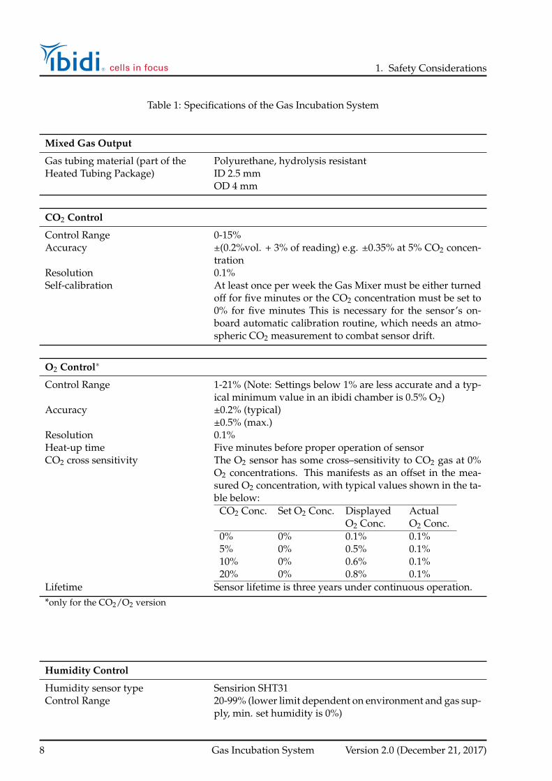
Table 1: Specifications of the Gas Incubation System
Electrical Specifications Power Supply
Protection class IIngress protection rating IP 20Overvoltage category IIExternal power supply AC 100-240 V, 50/60 Hz, 1.4 AInput line voltage Gas Mixer DC 24 V, 5 A, 120 WOutput voltage (to HumidifyingColumn)
DC 24 V
Operating Conditions
Operating area Enclosed roomsEnvironmental operating tempera-ture
18-30°C/64-86°F
Operating humidity max. 80% relative humidity (RH)Operating Altitude max. 2000 m (atmospheric pressure 800-1060 hPa/11.6-15.4
psi)Storage Conditions -5-50°C/23-122°F, humidity <60% relative humidity (RH)
Outer Dimensions and Characteristics of the Components
Gas Mixer 90 × 170 × 230 mm3
2230 g/4.9 lbsHumidifying Column 70 × 110 × 300 mm3
660/710/790 g /1.45/1.57/1.74 lbs (empty/min/max)Heated Tubing Package 0.6 m (between Controller and Column)
1.5 m (between Column and Heated Lid)82 g/0.18 lbs
Cable for Humidity Sensor 1.5 mUSB cable 1.8 mPower supply cable 2.0 m (power supply to wall)
1.2 m (power supply to device)
Gas Supply (Input)
Gas tubing material Polyurethane, hydrolysis resistant(Supplied with the system) ID 4 mm
OD 6 mmConnection to the Gas Mixer Push-in fittingConnection to the Heated Lid Male Luer LockPressurized Air (Blue tubing) 1 bar optimum / 14.5 psi (0.8-1.2 bar / 11.6-17.4 psi)Carbon dioxide (CO2) (Green tub-ing)
1 bar optimum / 14.5 psi (0.8-1.2 bar / 11.6-17.4 psi)
Nitrogen (N2) (Yellow tubing)* 1 bar optimum / 14.5 psi (0.8-1.2 bar / 11.6-17.4 psi)*only for the CO2/O2 version
Version 2.0 (December 21, 2017) Gas Incubation System 7
1. Safety Considerations
Table 1: Specifications of the Gas Incubation System
Mixed Gas Output
Gas tubing material (part of the Polyurethane, hydrolysis resistantHeated Tubing Package) ID 2.5 mm
OD 4 mm
CO2 Control
Control Range 0-15%Accuracy ±(0.2%vol. + 3% of reading) e.g. ±0.35% at 5% CO2 concen-
trationResolution 0.1%Self-calibration At least once per week the Gas Mixer must be either turned
off for five minutes or the CO2 concentration must be set to0% for five minutes This is necessary for the sensor’s on-board automatic calibration routine, which needs an atmo-spheric CO2 measurement to combat sensor drift.
O2 Control∗
Control Range 1-21% (Note: Settings below 1% are less accurate and a typ-ical minimum value in an ibidi chamber is 0.5% O2)
Accuracy ±0.2% (typical)±0.5% (max.)
Resolution 0.1%Heat-up time Five minutes before proper operation of sensorCO2 cross sensitivity The O2 sensor has some cross–sensitivity to CO2 gas at 0%
O2 concentrations. This manifests as an offset in the mea-sured O2 concentration, with typical values shown in the ta-ble below:
CO2 Conc. Set O2 Conc. DisplayedO2 Conc.
ActualO2 Conc.
0% 0% 0.1% 0.1%5% 0% 0.5% 0.1%10% 0% 0.6% 0.1%20% 0% 0.8% 0.1%
Lifetime Sensor lifetime is three years under continuous operation.*only for the CO2/O2 version
Humidity Control
Humidity sensor type Sensirion SHT31Control Range 20-99% (lower limit dependent on environment and gas sup-
ply, min. set humidity is 0%)
8 Gas Incubation System Version 2.0 (December 21, 2017)

1. Safety Considerations
Table 1: Specifications of the Gas Incubation System
Sensor Accuracy 2.5% (max.)Resolution 0.1%
Humidifying Column Temperature Control*
Control Range Ambient water temperature to 50°C (min set temp 0°C)Accuracy 1% (absolute)Resolution 0.1%*only controllable on the Gas Mixer
Flow Control Mixed Gas
Control Range 0-20 l/hAccuracy ±25%Resolution 0.1%
Humidifying Column
Liquid Ultra-pure waterMinimum volume 50 mlMaximum volume 130 mlRefilling 80 ml (approximately after 7 days)
Version 2.0 (December 21, 2017) Gas Incubation System 9

1. Safety Considerations
1.6 Notices
Disclaimer
• ibidi shall not be held liable, either directly or indirectly, for any damage incurred as a result ofproduct use.
• Prohibitions on the use of ibidi software
– Copying software for other than backup purposes
– Transfering or licensing of the right to use software to a third party
– Disclosure of confidential information regarding software
– Modification of software
• The contents of this manual are subject to change without notice for product improvement.
• This manual is considered complete and accurate at publication.
• This manual does not guarantee the validity of any patent rights or other rights.
• If an ibidi software program doesn’t function properly, this may be caused by a conflict fromanother program operating on the computer. In this case, take corrective action by uninstallingthe conflicting product(s).
• ibidi is a registered trademark of ibidi GmbH in Germany and other countries.
WARNING!
• Only operate the Gas Incubation System with the supplied components.
• Only use the cables and plugs delivered with the system. The power plug of the control unitmust be inserted in an outlet with a ground (earth) contact.
• Do not replace detachable power cables by power cables with inadequate specifications. Byviolating these instructions you risk electric shock and fire.
• Only use extension cables that have a protective ground wire.
• Do not operate the Gas Incubation System under conditions that pose a risk of explosion, implo-sion, or the release of gases. Only operate the Gas Incubation System with aqueous solutions.
• Do not operate a damaged Gas Incubation System. If the housing seems damaged or somethingis rattling inside the controller, contact the ibidi service hotline for repair.
• Some accessible parts of the Gas Incubation System (Humidifying Column base, water insidethe column, and Heated Tubing Package) can reach temperatures up to 50°C/122°F. Avoidtouching the temperature–controlled parts of the system when hot.
CAUTION
10 Gas Incubation System Version 2.0 (December 21, 2017)

1. Safety Considerations
• Ensure that the external power supply is easily accessible. The Gas Incubation System mustbe installed in a manner that none of its components hinders the access to the external powersupply.
• Immediately replace damaged cords, plugs, or cables to avoid a risk of personal injury or dam-age to the instrument.
• Only ibidi technical staff is permitted to open and service the Gas Incubation System.
• The external power supply should not be brought into contact with moisture. If the housing isdamaged, the external power supply should not be used.
• Avoid strong magnetic fields and sources of high frequency. The Gas Incubation System mightnot function properly when located near a strong magnetic field or high frequency source.
• Avoid vibrations from vacuum pumps, centrifuges, electric motors, processing equipment, andmachine tools.
• Avoid dust and corrosive gas. Do not install the Gas Incubation System where it could beexposed to high levels of dust or to outside air or ventilation outlets.
• Install the Gas Incubation System in a horizontal and stable position, which includes a table,bench or desk upon which the instrument is installed.
• Install the Gas Incubation System in a location that enables easy access for maintenance.
• Do not place heavy objects on the instrument.
• The Gas Mixer needs a gas input of 1 bar/14.5 psi. Only operate the Gas Mixer with the pressureindicated in the specifications on page 7.
Version 2.0 (December 21, 2017) Gas Incubation System 11

1. Safety Considerations
1.7 Limited Warranty
Products manufactured by ibidi, unless otherwise specified, are warrantied for a period of one yearfrom the date of shipment to be free of defects in materials and workmanship. If any defects in theproduct are found during this warranty period, ibidi will repair or replace the defective part(s) orproduct free of charge.
This warranty does not apply to defects resulting from the following:
1. Improper or inadequate installation.
2. Improper or inadequate operation, maintenance, adjustment or calibration.
3. Unauthorized modification or misuse.
4. Use of unauthorized tubing or fluidic connectors.
5. Use of consumables, disposables and parts not supplied by an authorized ibidi distribu-tor.
6. Corrosion due to the use of improper solvents, samples, or due to surrounding gases.
7. Accidents beyond ibidi’s control, including natural disasters.
This warranty does not cover consumables, such as cell culture chambers and dishes, tubes, fluidicconnectors, reagents etc.
The warranty for all parts supplied and repairs provided under this warranty expires on the warrantyexpiration date of the original product.
1.8 Transporting the Gas Incubation System
The weight of the Gas Mixer is approx. 2.3 kg/5.07 lbs. The weight of the Humidifying Column isapprox. 0.66 kg/1.5 lbs. Moving the devices during operation will pose a risk of personal injury ordamage to the instrument.
For transport, switch off the Gas Mixer, close all gas input lines and then disconnect all cables andtubing from the controller and peripheral components. Leave the instrument to cool down for ap-proximately five minutes. Carry the devices carefully and avoid mechanical shocks.
WARNING!
Close all gas input lines before disconnecting the gas tubing from the Gas Mixer!
12 Gas Incubation System Version 2.0 (December 21, 2017)

1. Safety Considerations
1.9 Repairing the Gas Incubation System
For inquiries concerning repair service, contact the ibidi service personnel and provide the modelname and serial number of your System.
ibidi GmbHService Hotline: [email protected]
CAUTION Do not try to repair the Gas Incubation System by yourself. Disassembly of the GasIncubation System is not allowed. Disassembly poses a risk of personal injury or damage to thedevices. Contact ibidi service personnel if there is need to disassemble the devices.
1.10 Waste Disposal – WEEE/RoHS Compliance Statement
The European Union (EU) has enacted two directives, the first on product recycling (Waste Electricaland Electronic Equipment, WEEE) and the second on limiting the use of certain substances (Restric-tion on the use of Hazardous Substances, RoHS).
1.10.1 EU Directive WEEE
The Gas Incubation System must be disposed of in compliance with the WEEE Directive 2012/19/EC.
This symbol on the product is in accordance with the European Union’s Waste Electrical and Elec-tronic Equipment (WEEE) Directive. The symbol indicates that this product must be recycled/dis-posed of separately from other household waste. It is the end user’s responsibility to dispose of thisproduct by taking it to a designated WEEE collection facility for the proper collection and recycling ofthe waste equipment. The separate collection and recycling of waste equipment will help to conservenatural resources and protect human health and the environment. For more information about recy-cling, please contact your local environmental office, an electrical/electronic waste disposal companyor distributor where you purchased the product.
1.10.2 EU Directive RoHS
Two Categories of products covered by the WEEE Directive are currently exempt from the RoHSDirective – Category 8, medical devices (with the exception of implanted or infected products) andCategory 9, monitoring and control instruments.
All of our products fall into either Category 8 or 9, and are currently exempt from the RoHS Directive.Nevertheless, the Gas Incubation System meets the requirements set forth in the RoHS Directive2011/65/EC.
Version 2.0 (December 21, 2017) Gas Incubation System 13

2. Principle
2 Principle
Physiological Conditions in Live Cell Imaging
The Gas Incubation System provides a controlled atmosphere of gas (CO2 and optionally O2) as wellas a defined humidity in the emitted gas stream that is flushed continuously through the stage topincubator. With the CO2/O2 version, oxygen can be reduced during the experiment, enabling theuser to perform hypoxia experiments. In combination with the Heating System it supplies completeincubator conditions for your live cell imaging directly on the microscope stage. Details about theHeating System are given in the Heating System instructions.
Heated Plate
Cell culture vesselwith medium
and cells
Heated Lid Gasinlet
Humidity sensor
Coverslip bottom
Figure 1: Schematic view of the Gas Incubation System combined with the Heating System.
14 Gas Incubation System Version 2.0 (December 21, 2017)

3. Equipment
3 Equipment
The Gas Incubation System in both versions is delivered with the complete set of cables and tubingneeded for the operation of the system.
3.1 Components of the Gas Incubation System
An overview of the different Gas Incubation System versions is given in this section. Table 2 lists allavailable options of the Gas Incubation System and table 3 shows all included components.
Table 2: Overview of the available Gas Mixer Systems
Cat. No. Description Components
11920 ibidi Gas Incubation System for CO2 Gas Mixer CO2Humidifying ColumnHeated Tubing PackageGas Tubing for CO2 and AirHumidity sensorHumidity sensor cableUSB cablePower cableUSB flash driveWrench for humidity sensor
11922 Gas Incubation System for CO2 and O2 Gas Mixer CO2/O2Humidifying ColumnHeated Tubing PackageGas Tubing for CO2, Air and N2Dead end tubingHumidity sensorHumidity sensor cableUSB cablePower cableUSB flash driveWrench for humidity sensor
Version 2.0 (December 21, 2017) Gas Incubation System 15

3. Equipment
Table 3: Overview of the components of the ibidi Gas Incubation System for CO2/O2 and ibidi GasIncubation System for CO2. The parts that are only available in the CO2/O2 version are marked withan asterisk (*). The drawings are not to scale.
Component Name Drawing
Gas Mixer
Humidifying Column
Heated Tubing Package: cables and tubing to connect the gas outletof the Gas Mixer, gas ports of the Humidifying Column and the gasinlet of the Heated Lid 1
2
Gas tubing for CO2, Air and N2*
Dead end tubing to close the N2 gas inlet*
Humidity sensor with counter nut to fix on the Heated Lid
Humidity sensor cable: Cable to connect the Gas Mixer to the hu-midity sensor
USB cable to connect the Gas Mixer with a computer
External power supply for the Gas Mixer
Country specific power cord to connect the external power supplyto the wall socket
16 Gas Incubation System Version 2.0 (December 21, 2017)

3. Equipment
Table 3: Overview of the components of the ibidi Gas Incubation System for CO2/O2 and ibidi GasIncubation System for CO2. The parts that are only available in the CO2/O2 version are marked withan asterisk (*). The drawings are not to scale.
Component Name Drawing
USB flash drive with IncuControl software
Wrench to fix the humidity sensor on the Heated Lid
*only for the CO2/O2 Version
3.2 Gas Mixer CO2 - CO2/O2
The Gas Mixer is the gas mixing unit of the ibidi Gas Incubation System. It combines the input gasesinto the correct mixture according to the values set on the display or in the software. There are twoversions of the Gas Mixer controlling either the amount of CO2 or the amount of CO2 and O2. Withthe CO2/O2 version, hypoxia conditions can be created by replacing O2 with Nitrogen (N2).
In addition to the gas mixture, the humidity of the incubation chamber is controlled by a feed-back loop using a humidity sensor located in the incubation chamber. The humidity is increasedby streaming the gas through a water column if the atmosphere is too dry.
Figure 2: Gas Mixer.
The Gas Incubation System can be run either as a stand-alone system or controlled via PC with theIncuControl software. A detailed description of the software can be found on the ibidi website.
The display on the front of the Gas Mixer shows the measured (’I’ = instantaneous) and set (’S’ = set)values of all four channels. You can set values and navigate through the menu by using the controlbuttons on the right.
Version 2.0 (December 21, 2017) Gas Incubation System 17
3. Equipment
ibidi Gas Mixer CO2 / O2
Up/right
Down/left
Select/con�rm
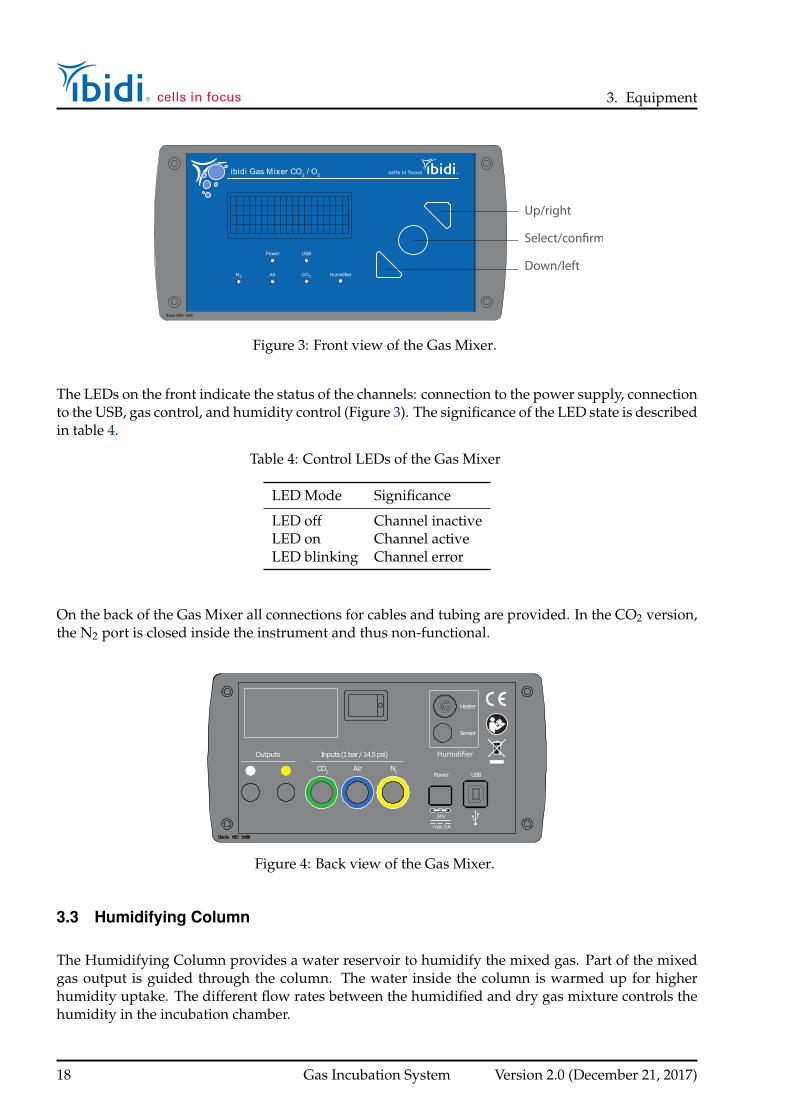
Figure 3: Front view of the Gas Mixer.
The LEDs on the front indicate the status of the channels: connection to the power supply, connectionto the USB, gas control, and humidity control (Figure 3). The significance of the LED state is describedin table 4.
Table 4: Control LEDs of the Gas Mixer
LED Mode Significance
LED off Channel inactiveLED on Channel activeLED blinking Channel error
On the back of the Gas Mixer all connections for cables and tubing are provided. In the CO2 version,the N2 port is closed inside the instrument and thus non-functional.
Sensor
Heater
24V
max.5A
CO2 Air N2
Outputs Inputs(1bar/14.5psi)
USBPower
Humidifier
Figure 4: Back view of the Gas Mixer.
3.3 Humidifying Column
The Humidifying Column provides a water reservoir to humidify the mixed gas. Part of the mixedgas output is guided through the column. The water inside the column is warmed up for higherhumidity uptake. The different flow rates between the humidified and dry gas mixture controls thehumidity in the incubation chamber.
18 Gas Incubation System Version 2.0 (December 21, 2017)

3. Equipment
Caution!
The Humidifying Column base heats up to 50°C/122°F when in operation.
The Humidifying Column has two gas connections (input and output) as well as an electric plug forthe heating of the column.
On top of the column is an opening for filling it with water. Open the blue stopper on top of thecolumn and fill the Humidifying Column with 130 ml of ultra-pure water. The maximum (∼ 130 ml)and minimum (∼ 50 ml) levels are indicated by the red labels inside the column (see Figure 5).
Filling Port
Tubing Connectors
Electric Plug
Water Level max.130 ml
Water Level min.50 ml
max. 50°C / 122°F CAUTION
HOT SURFACE
Stopper
Figure 5: Humidifying Column.
Caution!
Always close the filling port tightly to prevent gas leakage and malfunction of the system!
Version 2.0 (December 21, 2017) Gas Incubation System 19

3. Equipment
3.4 Heated Tubing Package
The Heated Tubing Package connects the gas output of the Gas Mixer to the Humidifying Columnand to the Heated Chamber on the microscope stage. To actively control the correct humidity, two gasoutputs are needed. One leads to the Humidifying Column and the other bypasses it. Both streamsare combined in the tubing leading to the stage top incubator. By varying the flow rates of the twogas streams, the humidity can be controlled.
The gas tubing carrying humidified gas is heated up to avoid condensation. For this purpose, aheating wire is inserted in the tubing. The wire is split off of the electrical cable under the insulatingjacket enclosing the tubing. The exact connection of the tubing is shown in Figure 6.
A
B
C
D
E
FG
HI 1
2
Figure 6: Heated Tubing Package: Electrical cable for the heating of the Humidifying Column (A),Insulating jacket (B), Mixed gas output white and yellow (C and D), heated wire split off the electricalcable (E), gas input to Humidifying column (F), gas output from Humidifying Column (G), mergingpoint, where the heating wire is led into the tubing (H), gas tubing to the Heated Chamber (I).
Caution!
Do not bend the Heated Tubing. The heating wire inside the tubing may be damaged by excessivebending.
3.5 Humidity Sensor
The humidity sensor is fixed in the side wall of the Heated Lid of the Heating System and measuresthe humidity inside the incubation chamber. It sits inside a small cavity in a black polymer block(Figure 7). This cavity must not be obstructed (e.g. covered with tape, pressed flat against the wall ofa disposable, etc.) for the sensor to function properly. The humidity sensor is connected with a cableto the Gas Mixer and measures the humidity inside the incubation chamber, enabling fast, activehumidity control.
20 Gas Incubation System Version 2.0 (December 21, 2017)

3. Equipment
Humidity sensor
Figure 7: Polymer block with humidity sensor and screws for fixation in the Heated Lid side wall.
To ensure accurate humidity measurements , the humidity sensor must be mounted securely in theplastic through-hole in the side of the Heated Lid. To do this, please follow the steps below:
1. Place the humidity sensor’s threaded connector through the opening in the Heated Lid wall,with the black polymer block’s long side parallel to the wall. The end of the polymer block withthe humidity sensor should be pointing towards the middle of the chamber.
2. Screw the counter nut from the outside onto the thread and tighten it snugly against the outerwall of the Heated Lid using the wrench provided with the Gas Mixer. The flat cut-away onthe counter nut should be facing away from the lid, allowing the wrench to fit properly overthe nut. Be careful not to over tighten the nut.
Counter nut
Through-hole
Polymer blockwith humidity sensor
Figure 8: Installation of the humidity sensor in the side wall of the Heated Lid.
Caution!
Make sure that the humidity sensor is not in contact with the Heated Lid. Heat transfer from theHeated Lid to the sensor can lead to low relative humidity readings, which in turn can lead tocondensation in the chamber.
The connection of the humidity sensor with the Gas Mixer is shown in Section 4.1.3.
Version 2.0 (December 21, 2017) Gas Incubation System 21

4. Operating the Gas Incubation System
4 Operating the Gas Incubation System
The Gas Mixer and Humidifying Column are placed next to the microscope stand. The tubing of theHeated Tubing Package must reach the Heated Lid and Heated Plate on the microscope stage.
Caution!
Do not place the Temperature Controller and Humidifying Column on the microscope stage! Thevibration might disturb the measurement.
Caution!
The components must be assembled in the following order:
1. Connect all tubing and cables.
2. Apply 1 bar (14.5 psi) to the connected gas tubing.
3. Switch on the Gas Mixer.
Not maintaining this hierarchy may lead to device malfunction or damage!
The procedure is explained in detail in the following sections.
4.1 Installation and Connection of the Parts
Figure 9 shows all connections of cables and tubing that are required for operation.
Heating Humidifying Column
External Humidity Sensor
USB connection
5A
External Power Supply
Output1
Output2
InputCO2
InputAir(Blue)
InputN2
Figure 9: Overview of the connection of all cables and tubing to the Gas Mixer. In the CO2 versionthe N2 port is not available.
22 Gas Incubation System Version 2.0 (December 21, 2017)

4. Operating the Gas Incubation System
4.1.1 Connection to the Gas Supply
The Gas Incubation System takes as input CO2 gas and pressurized air, as well as N2 gas (onlyGas Mixer CO2/O2). Pressurized air can be supplied by the lab gas line or a small air pump orcompressor.
The gases from the bottle or laboratory gas line need to be connected to the Gas Mixer with the OD 6mm polyurethane tubing in the respective color. This tubing is delivered with the system.
Table 5: Available connections and color code in the two different Gas Mixer versions
Gas Input Gas Incubation System for CO2 Gas Incubation System for CO2/O2 TubingColor
CO2 1 bar/14.5 psi 1 bar/14.5 psi greenAir 1 bar/14.5 psi 1 bar/14.5 psi blueN2 – 1 bar/14.5 psi yellow
CO2Air N2
Inputs (1 bar)
Figure 10: Connection of the gas tubing to the Gas Mixer. The N2 port is closed and not available inthe CO2 version.
To connect the gas tubing to the Gas Mixer push the tubing into the push-in fittings. The functionalprinciple is shown in Figure 11.
Push
A
Push
PushB
Pull
Figure 11: How to connect and disconnect the gas tubing to the push–in fittings. Push in to connect(A). Push and pull to disconnect (B).
Warning!
Only disconnect the tubing when there is no pressure on the gas line. First, switch off the pressurefrom the gas line. Control the remaining pressure on the gas line’s pressure reducing valve. Then,remove the tubing.
Version 2.0 (December 21, 2017) Gas Incubation System 23

4. Operating the Gas Incubation System
Attention!
Always connect all gas input ports with the appropriate gas (1 bar/14.5 psi). Do not leave anyinput ports open.CO2/O2 version: In case the N2 input is not needed (CO2/O2 Version only), close the N2 inputport using the provided dead-end tubing (Figure 12).
N2
Position „OFF“
Figure 12: Close the N2 port of the Gas Mixer with the dead end tubing if not needed (CO2/O2version only).
4.1.2 Connection of the Heated Tubing Package and the Humidifying Column
To operate the Gas Incubation System, the tubing and cables of the Heated Tubing Package mustbe connected, as well as the humidity sensor cable and the power cord. The connection diagram isshown in Figure 13.
There are two lines coming from the Gas Mixer output. One goes to the Humidifying Column, theother directly to the Heated Chamber.
Table 6: Connection of the gas lines with color code of the mixed gas
Color Code
Output white (Gas Mixer back wall) Blue tubing with white labelOutput yellow (Gas Mixer back wall) Blue tubing with yellow labelOutput red (Humidifying Column base) Blue tubing with red labelInput blue (Humidifying Column base) Blue tubing with blue label
1. Connect the two gas outlets of the Gas Mixer to the white (1) and yellow (2) marked gas tubingto Output 1 and Output 2 on the back wall of the Gas Mixer.
2. Connect the plug of the electrical cable (next to the white and yellow gas tubing) to the ”Heater”socket.
3. Connect the blue and red marked gas tubing to the respective inputs on the Humidifying Col-umn.
24 Gas Incubation System Version 2.0 (December 21, 2017)

4. Operating the Gas Incubation System
4. To connect the electrical cable to the Humidifying Column, plug the cable into the connector onthe column’s base. Please make sure red dot on the cable and connector line up. Gently pushto connect the plug.
5. To connect the mixed and humidified gas output to the Heated Chamber, screw the Luer Lockadapter into the metal adapter that is fixed in the wall of the Heated Lid.
5A
max. 50°C/122°FCAUTION
HOT SURFACE
Figure 13: Connection of the Heated Tubing Package to the Gas Incubation System.
Warning!
Do not disconnect the Heated Tubing while the Gas Mixer is running. The resulting suddenchange of pressure may lead to damage to the Gas Mixer.
4.1.3 Connection of Cable for Humidity Sensor
The humidity sensor should be mounted in the Heated Lid of the Heating System (see Section 3.5).To operate the Gas Incubation System with humidity control, the cable for humidity sensor must beconnected between the Gas Mixer and the humidity sensor.
1. Plug the cable for the humidity sensor into the Gas Mixer in the connector labeled ”Sensor”.Make sure that the red dots on the cable and connector line up.
2. Connect the other end to the humidity sensor mounted in the Heated Lid , as shown in Figure14. Again make sure that the red dots on cable and connector line up.
Version 2.0 (December 21, 2017) Gas Incubation System 25

4. Operating the Gas Incubation System
Figure 14: Connection of the cable for humidity sensor to the humidity sensor.
4.1.4 Connection of Power Supply and USB (optional)
To finish the setup, the power supply must be connected. Optionally the USB cable can be used toconnect the Gas Mixer to an external computer. This enables the use of the IncuControl softwaredelivered with the system (Section 5) for logging and controlling the parameters of the experiment.
• Plug the power supply into the connector on the Gas Mixer labeled ”Power”.
• Connect the other end to the wall socket.
• Optional: Connect the computer to the Gas Mixer with the USB cable supplied.
4.2 Re-filling the Humidifying Column
The column should be refilled before the water level falls below the lower red mark (Figure 5).
Water Level max.130 ml
Water Level min.50 ml
max. 50°C / 122°F CAUTION
HOT SURFACE
Figure 15: (Re-)Filling of the Humidifying Column.
26 Gas Incubation System Version 2.0 (December 21, 2017)

4. Operating the Gas Incubation System
Refill the column with ultra–pure water up to a maximum of 130 ml (total volume, marked in red).This can be done during operation of the Gas Incubation System, without stopping the Gas Mixer.Note that refilling the column during operation may lead to a temporary drop in the chamber’shumidity.
The length of intervals between refillings depends on set points of the humidity and flow on the GasMixer.
Caution!
Always close the filling port tightly to prevent gas leakage and malfunction of the system!
4.3 Switching on the System
Make sure that all cables and tubing are connected as shown, and that the Humidifying Column isfilled with ultra-pure water.
1. Set your gas regulation valve to the recommended pressure of 1 bar (14.5 psi).
2. Switch on the Gas Mixer and wait for ”self test” (all systems) and ”heat up” (only CO2/O2versions).
3. Check the parameters on the display.
4. Give the system time to equilibrate all parameters for a minimum of 30 minutes.
Note
Immediately after powering up, the Gas Mixer runs a flow sensor calibration routine for severalseconds. The display shows ”self-test”.
After this, the Gas Mixer for CO2/O2 will automatically start a warm–up routine for five min-utes. The display shows a blinking ”heat up”. After five minutes, the device will begin normaloperation. The CO2 version is ready for operation immediately after the ”self test”.
For an optimal start, we recommend using the values given in Table 7. The full specification range isindicated in the specifications (Section 1.5).
Caution!
Be aware that when the system is switched on, some parts of the tubing are actively heated:The Humidifying Column base (max. 50°C/122°F), the water in the Humidifying Column (max.55°C/131°F) and the Heated Tubing Package (max. 40°C/104°F outside).
Version 2.0 (December 21, 2017) Gas Incubation System 27

4. Operating the Gas Incubation System
4.4 Setting Parameters in the Control Panel
All control parameters can be manually set on the controller using the buttons and the display on thefront panel.
ibidi Gas Mixer CO2 / O2
Up/right
Down/left
Select/con�rm
Figure 16: Gas Mixer with Control Panel.
The cursor position is indicated with square brackets (”[xxx]”). You can move the cursor using the”Left” and ”Right” buttons. If you want to select a parameter or a function, you need to press the”Select” button. When you select a parameter, the square brackets will change to angle brackets(”<xxx>”). Now you are able to change the value up or down. To confirm the changed value, youmust press the ”Confirm” button once more. When selecting a function, you will see the individualfunction view, which is where you can change the parameters or access further functions.
Table 7: Recommended parameters for the operation of the Gas Incubation System
Parameter Recommended Values
CO2 (%) 5-10% depending on bufferO2* (%) 20% (see Figure 17)Humidity (%) 90-95%Column Temperature (°C) 45-50°C*for CO2/O2 Version only
4.4.1 Humidity Regulation
In the case of condensation in the chamber, decrease the humidity accordingly.
Humidity values at the lower end of the control range can only be achieved using dried compressedair or with a compressed air pump in a very dry environment. The exact value of the lower limit willvary depending on the amount of water vapor present in the input gases used, the pressure, and thetemperature of the measured environment.
28 Gas Incubation System Version 2.0 (December 21, 2017)

4. Operating the Gas Incubation System
4.4.2 O2 Regulation/Hypoxia (Gas Mixer for CO2 and O2 only)
Please keep in mind that in a CO2/air mixture, the O2 concentration will drop when the CO2 concen-tration is raised. The maximum oxygen concentration thus decreases according to the CO2 value youhave chosen. Please see the graphic below for estimating the maximum O2 concentration in your gasmix for a set CO2 concentration. For example, when setting the CO2 concentration to the commonvalue of 5%, the maximum oxygen level is decreased to 20% O2 (see Figure 17).
00
5
5
10
10
15
15
20
25
2520
Poss
ible
O2 C
once
ntra
tion
[%]
Set CO2 Concentration [%]
Figure 17: Maximum O2 concentrations at different CO2 concentrations in gas mixtures from the GasMixer.
For generating hypoxia conditions, set the oxygen to the target value. The O2 will be replaced bynitrogen (N2) until the set value is reached.
Version 2.0 (December 21, 2017) Gas Incubation System 29
5. IncuControl Software
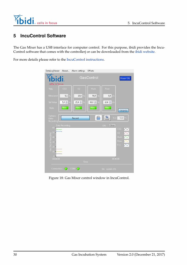
5 IncuControl Software
The Gas Mixer has a USB interface for computer control. For this purpose, ibidi provides the Incu-Control software that comes with the controllerj or can be downloaded from the ibidi website.
For more details please refer to the IncuControl instructions.
Figure 18: Gas Mixer control window in IncuControl.
30 Gas Incubation System Version 2.0 (December 21, 2017)
6. Maintenance
6 Maintenance
6.1 Flow Sensor Auto-Recalibration
At least once per week the Gas Mixer must be either turned off for 5 minutes. This is necessary for theflow sensor’s onboard automatic calibration routine, which needs an atmospheric CO2 measurementto compensate sensor drift. When again switching on the system, the flow sensor calibration is runautomatically (see Section 4.3).
6.2 Disinfection and Cleaning
6.2.1 Wiping the Outer Surface
To clean the Gas Mixer and Humidifying Column from the outside, switch the Gas Mixer off anddisconnect all cables and tubing. Leave the instrument to cool down for approximately five min-utes. Use only dry cloth or a cloth dampened with water (ultrapure) or common lab disinfectionsolutions that are based on quaternary ammonium compounds (e.g., Barrycidal 36 or Pharmacidal).Fingerprints can be removed using ethanol or isopropanol (70%) or lens/eyeglass cleaning wipes.
CAUTION:
70% ethanol or isopropanol can be used to wipe the Humidifying Column from the outside. Donot use any other organic solvents. Do not expose to ethanol or isopropanol for an extendedperiod of time. It can lead to damage of the Humidifying Column.
6.2.2 Cleaning the Column’s Inner Face
Microbial contamination in the Humidifying Column is usually not a problem since distilled waterand light–starved environments (microscopy rooms) do not support microbe growth. If, however,contamination has occurred, disinfect the Humidifying Column by running the system with 3% hy-drogenperoxide for 1 hour. Subsequently wash with water. The use of anti–microbial agents is notrecommended since they can be transported as aerosol and end up in the specimen.
6.3 Influence of Surrounding Temperature and Airflow
The surrounding, ambient temperature affects the temperature inside the microscopy chambers. De-vices, such as computers and camera controllers, can significantly heat up small rooms. In this case,we recommend equilibrating the room temperature to the typical experimental conditions at least2-3 hours before starting the experiment.
Airflow can enhance the effect of temperature changes in the vicinity of the incubation chamber. Incases where airflow (e.g., air conditioning) cannot be stopped, we recommend protecting the micro-scope as much as possible from it.
Version 2.0 (December 21, 2017) Gas Incubation System 31

7. Troubleshooting
7 Troubleshooting
7.1 Focus Not Stable
Focus drift can be a problem in long–term time–lapse experiments. Focus stability is mainly influ-enced by mechanical changes and temperature variations. Follow these recommendations to keepyour cells in focus:
• Switch on all components (heating, gas incubation, computer, other equipment) at least 60 min-utes before starting the experiment.
• After you put a slide or dish onto the microscope, wait 30 minutes before starting a time-lapseexperiment to achieve temperature and immersion oil equilibration. *
• Keep the room temperature as stable as possible. Air conditioning should either be workingcontinuously or switched off.
• Do not change the temperature during the experiments. Avoid door/window openings, as thiscan lead to temperature fluctuations.
• Eliminate all sources of mechanical vibrations. Use a damped table for your microscope.
* If the experiment needs to be started immediately, we recommend monitoring the focus for 20minutes. In the first few minutes after starting the experiment, temperature equilibration mightinfluence the focus/Z-position of the cells.
7.2 Evaporation Too High
Depending on the incubating conditions, small volumes might evaporate quickly, especially duringlong–term experiments. We suggest increasing the set value of the relative humidity. For specialexperiments, we recommend using Parafilm (Pechiney Plastic Packaging Company) or a silicone oil(ibidi Anti-Evaporation Oil, Cat. No. 50051) to decrease evaporation.
7.2.1 Parafilm Procedure
Small stripes of Parafilm fitted onto the reservoirs of the slides are very effective at preventing evap-oration effects. Fill the slide, as recommended e.g. in the ibidi labware instructions, then adapt theParafilm until it fits tightly.
7.2.2 Silicone Oil Procedure (ibidi’s Anti-Evaporation Oil)
Covering the medium with sterile silicone oil drastically reduces evaporation effects and is compati-ble with cell culture. Please don’t use mineral oil, as this is harmful to some slides and dishes.
Equilibrate oil and medium inside the incubator overnight. This step helps avoid the formation ofair bubbles, and pre–warms the solutions to 37°C. Afterwards, fill your slide with cells and medium.Cover the medium’s surface with an appropriate amount of silicone oil.
32 Gas Incubation System Version 2.0 (December 21, 2017)

7. Troubleshooting
7.3 Gas Flow too low
7.3.1 Gas Input open without connected gas
Always connect all gas input ports with the appropriate gas and pressure (1 bar/14.5 psi). Do notleave any input ports open. In case N2 is not needed or available, close the input port by using theprovided dead-end tubing.
7.3.2 Gas Pressure too low
Always use the recommended pressure of 1 bar/14.5 psi.
7.3.3 Set Values are too high or too low
Please make sure the set values are set to ambient air values (0% CO2, 21% O2) in case the cor-responding gas is not connected. Additionally, keep in mind that the maximum O2 concentrationdepends on the set CO2 concentration. See page 29 for further details.
7.4 Condensation Inside the Incubator
Check the temperature of the chamber (Heated Lid and Heated Plate). Make sure the humiditysensor is not in contact with the Heated Lid. In case of condensation, decrease the humidity andair–dry the incubator if necessary.
Please contact ibidi at [email protected] for further troubleshooting help.
Version 2.0 (December 21, 2017) Gas Incubation System 33