instruction manual - hydrologicalsolutions.com manual deployment ... slick soil conditions and other...
TRANSCRIPT

Instruction Manual
1

TABLE OF CONTENTS
3 Introduction 4 Stabilization components 5 Accessories 6 Baffle behavior 7 Connection method 8 Lifting pipe procedure 9 Lifting timber procedure 10 Worksite safety 11 Hazards 12-13 Safeguards and procedures 14 Site preparation 15-16 Freezing conditions 17-18 Important information when using cofferdams 19 Using pipe support 20 Installation configurations 21 Proper use of a suction hose 22 Evacuation procedures 23 Seepage disclaimer 24 Diversion pipe and bypass pump applications 25 Over-inflation prevention 26 Installation procedure 27 Deployment and removal using 1 track hoe and shoreline anchor 28-29 Deployment and removal using 2 track hoes 30-31 Manual deployment 32 Removal procedure 33 Folding procedure 34 Repair instructions 35 Maintenance, storage, definitions 36 Material specification 37 Warranty
2

Introduction Aqua-Barriers® are a U.S. patented #5865564 water-inflated damming devices produced from flexible reinforced PVC membrane material. The Aqua-Barriers® are used as a temporary water diversion system in construction projects, flood protection and numerous other applications. Aqua-Barriers® are characterized by being light-weight, easily deployed and removed, compact in storage, repairable and reusable. Stabilization Components Three components interact together to stabilize the Aqua-Barrier® water-inflated dam. The internal baffle system The patented internal restraint baffle(s) lock into place when the barrier is exposed to uneven hydrostatic pressure on one side. Freeboard (amount of inflated barrier above the surrounding water level) A minimum of at least 25% freeboard required in all Aqua-Barrier® installations. Freeboard requirements may increase if the barrier is exposed or has the potential to being exposed to high water velocities (3-ft or more per second), slick soil conditions and other relevant hydrostatic conditions. Surface Friction The Aqua-Barriers also require surface friction to stabilize when exposed to uneven hydrostatic pressures. Barriers that are exposed to weak soils and/or slick soil conditions may require pipe support, a wider footprint or additional freeboard
3

STABILIZATION COMPONENTS
4

AQUA-BARRIERS ARE EQUIPPED WITH UNIQUE ACCESSORIES FACILITATE INSTALLATION AND REMOVAL
5

Barrier height Maximum adjustment length
2’ 1’ 3’ 1.5’ 4’ 2’ 5’ 2.5’ 6’ 3’ 7’ 3.5’ 8’ 4’
AQUA-BARRIER BAFFLE BEHAVIOR The Aqua-Barrier system gains its stability through the tensioning of the inner restraint baffle(s).Once
the system is inflated the baffles prevent the barrier from rolling. As the barrier is exposed to water pressure there is a natural adjustment towards the side of the least hydrostatic (water) pressure.
MEASURE BARRIER HEIGHT FROM THE LOWEST ELEVATION
ALWAYS INFLATE AN AQUA-BARRIER TO ITS FULLEST HEIGHT These adjustment lengths are based upon a barrier being inflated to its recommended height with the baffle being cross-sectional centered. The barrier adjustment length could increase or decrease if not
properly inflated and or if slopes or grades are present. These adjustments should be considered when determining the installation location of the barriers.
The chart below illustrates the maximum adjustment per each barrier height
6

CONNECTION METHOD Aqua-Barriers are joined together by an overlapping technique. Once the initial Aqua-Barrier has been inflated, the adjoining barrier is positioned and pulled up onto the end of the inflated barrier. The chart below illustrates the standard barrier overlap lengths.
MEASURE BARRIER HEIGHT FROM THE LOWEST ELEVATION
ALWAYS INFLATE AN AQUA-BARRIER TO ITS FULLEST HEIGHT
The barrier positioned on top of the inflated barrier is then inflated. The weight of the second barrier will provide downward force to seal the connection joint. Barriers can be joined end to end or at various other angles as shown on the configuration page 18.
Aqua-Barrier Inflated Height (ft) Overlap Length (ft) 2 3 3 4.5 4 6 5 7.5 6 9 7 10.5 8 12
End to End 45 Degree Angle Corner to Corner 7

LIFTING PIPE INSTALLATION PROCEDURE ALL STEEL PIPES MUST BE CONTINUOUS LENGTHS WITH NO JOINTS OR CONNECTIONS
Step 1: Insert 3 inch diameter schedule 40 steel pipe into pipe loop. Required Pipe Lengths
Step 2: Locate cut outs along pipe loop. Connect additional 3 inch schedule 40 steel pipe parallel to the pipe in the pipe loop by using (5) 3/4 inch x6 feet long sections of nylon rope.
Step 3: Attach (3) 3/4 inch x 15 feet nylon ropes to the 3 inch diameter pipe at the cut outs. These three ropes should then be attached to the lifting apparatus.
Barrier Height Pipe Length
3' 8'
4' 10'
5' 15'
6' 15'
7' 21'
8' 21'
8
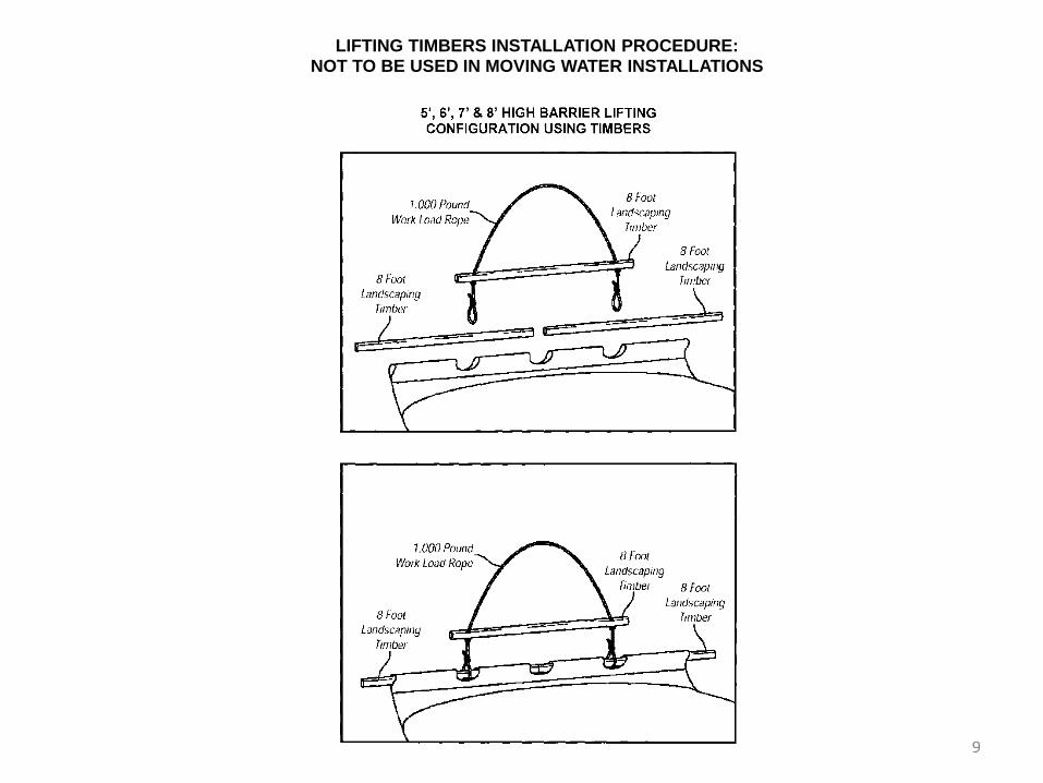
LIFTING TIMBERS INSTALLATION PROCEDURE: NOT TO BE USED IN MOVING WATER INSTALLATIONS
9

When working within the Aqua-Barrier dewatered area it is required that all federal, state and local safety procedural laws are followed. At a minimum, the company utilizing the Aqua-Barrier system must comply with OSHA trench and excavation safety procedures. These regulations can be found online at www.osha.gov. A competent person(s) is required onsite at each work shift during the use of the Aqua-Barrier system when workers are present. The competent site person is required to inspect the barriers if there has been any change in water depth, height of inflated barrier(s) or change in position. The OSHA definition of a competent person is as follows: COMPETENT PERSON is an individual who is capable of identifying existing and predictable hazards or working conditions that are hazardous, unsanitary or dangerous to employees, and who has authorization to take prompt corrective measures to eliminate or control these hazards and conditions.
WORKSITE SAFETY
10

• Due to close proximity of water, Hydrological Solutions, Inc recommends the use of a Coastal Guard approved Personal Floatation Device during the installation and removal process of an Aqua-Barrier. • Aqua-Barriers can slide into the dewatered worksite in the event that the designated freeboard requirement provided by the Hydrological Solutions, Inc. representative is exceeded. Minimum freeboard requirements are 25%. Aqua-Barriers can be pushed or floated downstream in a moving water environment. • Aqua-Barriers can slide into the dewatered area if the surface friction is not stable enough to support the barrier. • Aqua-Barriers can lose their stability and be forced into the dewatered area if its recommended inflation height is not maintained. • Aqua-Barriers®can be vandalized by cutting the exterior of the system or removing the drain ports. • Please inquire and adhere to all Overhead Power Line Safety laws and OSHA requirement when elevating the Aqua-Barriers. Hydrological Solutions, Inc. Cares about the safety of those working near electrical sources. Accidents involving contact with high voltage can result in serious injury or death. When power lines are present on or near the work site, the safety of the equipment operation is the responsibility of the personnel in charge of the work site. Before setting up or operating equipment on any project: EVALUATE THE WORK SITE FOR ELECTRICAL HAZARDS, including both overhead and underground, and if present EXERCISE EXTREME CAUTION.
The preceding list of hazards does not represent every conceivable potential hazard that may appear at a given worksite. Any change in the Aqua-Barriers original installation positions must be evaluated before
workers and equipment are allowed into the work area. The local Hydrological Solutions, Inc. representative or our installation department (800/ 245-0199) must be contacted to discuss the safety of the
Aqua-Barrier system before workers or equipment are allowed back into the work area.
HAZARDS
11

Caution: Read the safeguards and precautions prior to installing or removing Aqua-Barrier water inflated dams. Follow instructions and heed all warnings in this manual. The below stated precautions are only a few of many. Each potential Aqua-Barrier installation location may require different precautions. It is required that a Hydrological Solutions, Inc.
representative be contacted and consulted prior to installing or removing Aqua-Barriers. See Aqua-Barrier Worksite Training document for more information on safety, installation and removal procedures.
SAFEGUARDS AND PRECAUTIONS
The OSHA trench & excavation guidelines should be followed at all times when working with Aqua-Barrier Due to proximity of water, Hydrological Solutions, Inc recommends the usage of a Coastal Guard approved PFD (Personal Floatation Device) during the installation and removal of an Aqua-Barrier Each individual involved with installing Aqua-Barriers® is required to have a cutting tool (i.e. knife, razor) readily accessible in the event of being trapped by a barrier. Every work site should have a deployment and recovery plan. Assistance can be provided regarding this plan by your local Hydrological Solutions representative Recommended safety space between workers and inflated barrier is 10ft to 12ft. If excavation is occurring near an Aqua-Barrier® more distance may be needed Personnel should avoid walking on inflated or deflated Aqua-Barriers A 10-ft operating distance should be maintained between heavy equipment and inflated Aqua-Barriers Personnel involved in the installation process should never position themselves beneath any elevated portion of an Aqua-Barrier® or piece of equipment. Please inquire and adhere to all Overhead Power Line Safety laws and OSHA requirement when elevating the Aqua-Barriers
12

SAFEGUARDS AND PRECAUTIONS
When work requires excavating in a dry environment provided by the Aqua-Barriers® and the excavation depth will exceed 1-ft, allow an additional easement area of 1ft in addition to the required 10-12ft from barriers and excavation area for each additional foot excavated When installing, working around inflated barriers, or removing Aqua-Barriers a minimum crew size of 3 workers is mandatory In construction applications it is recommended to monitor the inflated Aqua-Barriers 24-hours a day. This will deter any vandalism and also be a source of information if any problems occur If barriers are installed near major roads, overpasses, or recreational boating areas it is recommended a puncture resistant cover be placed on barriers to protect against thrown objects An Aqua-Barrier, empty or inflated, should never be dragged or pulled across any surface. This may cause permanent surface damage to the barrier. Aqua-Barriers are only a surface treatment. Water can transmit under the barriers depending on soil porosity. Sump pump area(s) are required in all dewatering projects. The size and number of sump pumps will depend upon the porosity of the soil. The review of a completed Worksite Assessment Sheet by an authorized Hydrological Solutions representative will determine the effectiveness of the Aqua-Barrier for a particular work environment.
13

SITE PREPARATION
Installing Aqua-Barrier in any type of environment requires thorough preparation. The following represents several general guidelines that need to be complied with when installing Aqua-Barriers
• All ground objects that could puncture Aqua-Barriers (i.e. sharp rocks, broken glass) should be carefully removed or avoided when deploying. If deploying in a standing or moving water environment, manually walking the site or drag netting will insure a properly cleared area. When the deployment site cannot be totally cleared of problem objects, it is required that a protective material be installed on the site (i.e. non-woven geo textile or other forms of puncture and abrasion resistant plastic sheeting) prior to deployment. • In construction and flood protection applications, 24-hour monitoring is recommended. This will deter any vandalism and also be a source of information if a barrier failure occurs.
• Avoid deploying Aqua-Barriers near any electrical source (i.e. ground transformers, power poles and lines, junction boxes and switch gears). Please inquire and adhere to all Overhead Power Line Safety laws and OSHA requirement when elevating the Aqua-Barriers. Hydrological Solutions, Inc. Cares about the safety of those working near electrical sources. Accidents involving contact with high voltage can result in serious injury or death. When power lines are present on or near the work site, the safety of the equipment operation is the responsibility of the personnel in charge of the work site. Before setting up or operating equipment on any project: EVALUATE THE WORK SITE FOR ELECTRICAL HAZARDS, including both overhead and underground, and if present EXERCISE EXTREME CAUTION.
• Assessment of slopes and land contours is very important when evaluating an optimal area for installing Aqua-Barriers. If the area needing protection is characterized by hills and valleys, barriers may only be needed in the valleys. A barrier will only fill to its expected inflated height at the lowest point it encounters along its length. It is important to consult your local Aqua-Barrier representative for assistance prior to deployment if faced with extreme land contours. Identify the water source that will be used to inflate barriers and maintain clear access to it. Deploy barriers where fill ports will be in close proximity with water source. Using the shortest length of hose to fill the Aqua Barriers is preferred because less hose transmits more water volume.
14

INSTALLING IN FREEZING CONDITIONS
In freezing conditions, it is recommended that all ice and snow be removed prior to installation. Failure to do so may affect barrier stability and integrity.
The barrier material is good to -22F. Anything below -22F makes the material brittle. Typically water inside the barrier is 10 degrees warmer than outside temperature. You can keep the water inside from freezing solid by using products such as glycol tubes (www.thawbuster.com ) – see next slide You can use ground heaters to warm up the barriers from the bottom (www.onsiteco.com/ground-thaw/ground-blankets) Thermal pool blankets to cover the top (www.backyardpoolsuperstore.com) may also be helpful. If you think the barriers will freeze you need to leave the fill ports open and release a little water out of the barriers. Water expands at a rate of 10% when it freezes. You want to make room inside the barriers to prevent rips in the material as water turns to ice. If the body of water in which the barriers are installed starts to freeze you may risk damage from ice ramming the barriers. To minimize this damage you can cover the barriers with a geo textile protective membrane or place something in front of them to “catch” chunks of ice. Concrete jersey barriers work well and sometimes PE construction fence has been used When it comes time to remove the barriers they must be fully thawed and drained before the track hoe begins to pull them out of the water. Do not attempt to remove a barrier with ice inside as it could cause damage.
15

GLYCOL TUBES REST ON TOP OF THE AQUA-BARRIERS
16

IMPORTANT INFORMATION WHEN USING WATER INFLATED COFFERDAM SYSTEMS
Establishing a temporary cofferdam system and dewatering the enclosed area is a process with inherent problems. These problems arise from the inability to gather exact site conditions because water coverage prevents visibility of the underwater surface conditions. Soil conditions directly under the visible surface may also pose unexpected problems such as objects that could damage the barrier and or porous soil
conditions. Extensive site evaluations can be performed; however, it is impossible to precisely determine all relevant hydrological conditions that could affect the success of the water inflated cofferdam system
Debris removal: It is imperative that all surface debris (ex. sharp rocks, rebar, stumps, etc.) that can puncture a plastic membrane be removed from the area where the barriers will be installed. An additional protective membrane can be deployed to provide additional puncture protection. The membrane must be formidable enough to provide the proper puncture protection according to the debris that the barriers will be exposed. If the debris is not removed you can potentially experience one or more of the following problems:
• Complete inability to keep a barrier inflated if large punctures occur. Recommended solution to problem is to remove barrier, perform onsite repair, and remove debris that caused the problem or apply protective membrane. If the damage has rendered the barrier un-repairable, a replacement unit will be needed.
• Loss of inflation due to small leaks in the barrier. Recommended solution would be either one of two options: 1. remove barrier, perform onsite repair, and remove debris that caused the problem or apply protective membrane. 2. Maintain recommended inflated height of barrier by adding water as needed.
Thorough site preparation is essential to avoiding the costly problems mentioned above
17

IMPORTANT INFORMATION WHEN USING WATER INFLATED COFFERDAM SYSTEMS
Moving water environments: Bodies of moving water can behave in unusual ways when partially or completely blocked with a temporary damming system. Reducing the normal channel dimensions can cause water depths and velocities to increase. Rain events, channel flows, irregular surface conditions, soil makeup, and other relevant hydrological information may affect the overall effectiveness of the damming system. Do to these unknown behaviors; the original cofferdam design may require alterations. Slick soil conditions: In environments exhibiting limited surface friction; adjustments to the freeboard (amount of inflated barrier above the surrounding water) and or a temporary structure may be required for barrier stabilization. Environments such as lakes, ponds, or other standing water environments are susceptible to long term silt build up. This soft silt media offers very little surface friction. Slopes, grades, and other relevant hydrological date can affect the ability of the inflated barrier to perform successfully in these environments. In the event that not enough soil friction exists to stabilize the system, a structural support such as steel pipes system can be used to achieve stability and prevent sliding.
18

Use steel pipes to support
barriers on slick surfaces, fast
moving water or freeboard loss
20ft long
3” diameter Schedule C
Driven 5ft into the ground Spaced 5-10ft apart
19
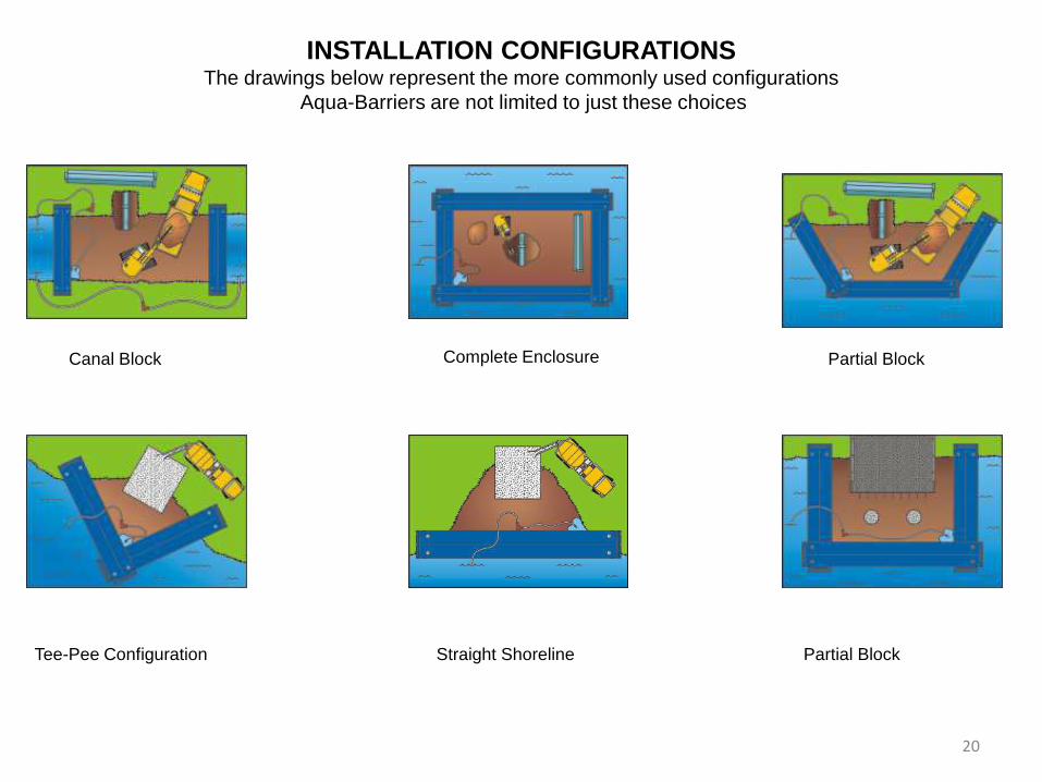
INSTALLATION CONFIGURATIONS The drawings below represent the more commonly used configurations
Aqua-Barriers are not limited to just these choices
Canal Block Partial Block
Complete Enclosure
Tee-Pee Configuration Straight Shoreline Partial Block
20

PROPER USE OF A SUCTION HOSE
CAUTION: AVOID INFLATING THE BARRIERS WITH ANY SOLIDS THAT CANNOTBE REMOVED DURING THE DEFLATION PROCESS. ADDITIONAL
CHARGES WILLAPPLY IF THE BARRIER INCURS DAMAGE BEYOND NORMAL WEAR AND TEAROR IF THE RETURN FREIGHT IS HIGHER DUE TO
EXTRA WEIGHT OF THE SHIPMENT.
21

EVACUATION PROCEDURES
In the event the water depth where the Aqua-Barriers are to be installed is expected to exceed the recommended 25% freeboard or recommended freeboard requirement, the worksite should be evacuated. The evacuation plan is as follows: All personnel should be evacuated from the dewatered worksite. The worksite equipment can be evacuated if the competent person believes that it is safe. The Aqua-Barrier removal process can begin if it is determined that there is sufficient time for removal of the barriers before the 25% freeboard requirement is exceeded. All personnel involved with the removal process should position themselves on the upstream side of the barriers before the actual removal process begins. Water should then be released from the barriers into the drained worksite area to equalize the water pressure on both sides of the barriers before opening the drain ports on the dewatered side of the barrier. Each installed Aqua-Barrier is to be removed from the worksite. A Hydrological Solutions, Inc. trained advisor will instruct onsite personnel with regard to the proper removal process during the installation training and removal session which may take place on site or by telephone prior to installation.
22

SEEPAGE DISCLAIMER The Aqua-Barrier water inflated dam system when properly installed is a temporary barrier against surface water. Hydrological Solutions, Inc. accepts no responsibility for water migrating under the Aqua-Barrier system. The volume of water migrating under the Aqua-Barrier is a function of soil porosity. A sump area where water can gather and be evacuated during the life of the project is required. The size and number of sump areas would depend on the size of the area being dewatered and porosity of the soil.
Use a pump on the dry side to control seepage that may occur
under the barrier due to weak and porous soil.
To control seepage you can apply bentonite clay on the watered side
of the barrier.
Another option to control seepage is to apply a row of sand bags on the
watered side of the barrier
23
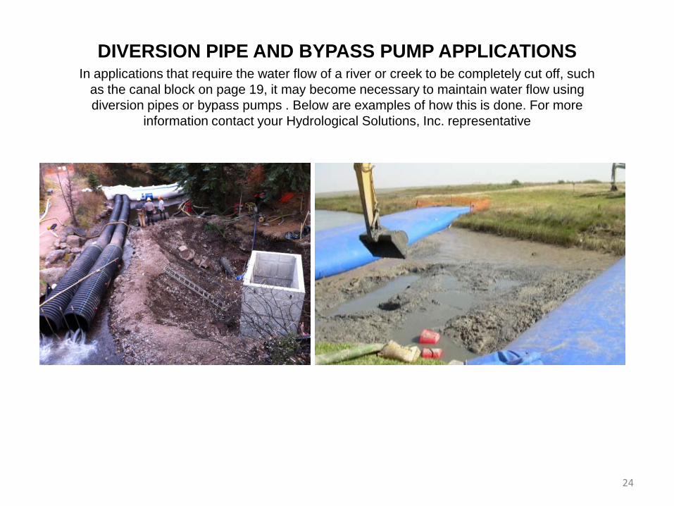
DIVERSION PIPE AND BYPASS PUMP APPLICATIONS In applications that require the water flow of a river or creek to be completely cut off, such
as the canal block on page 19, it may become necessary to maintain water flow using diversion pipes or bypass pumps . Below are examples of how this is done. For more
information contact your Hydrological Solutions, Inc. representative
24
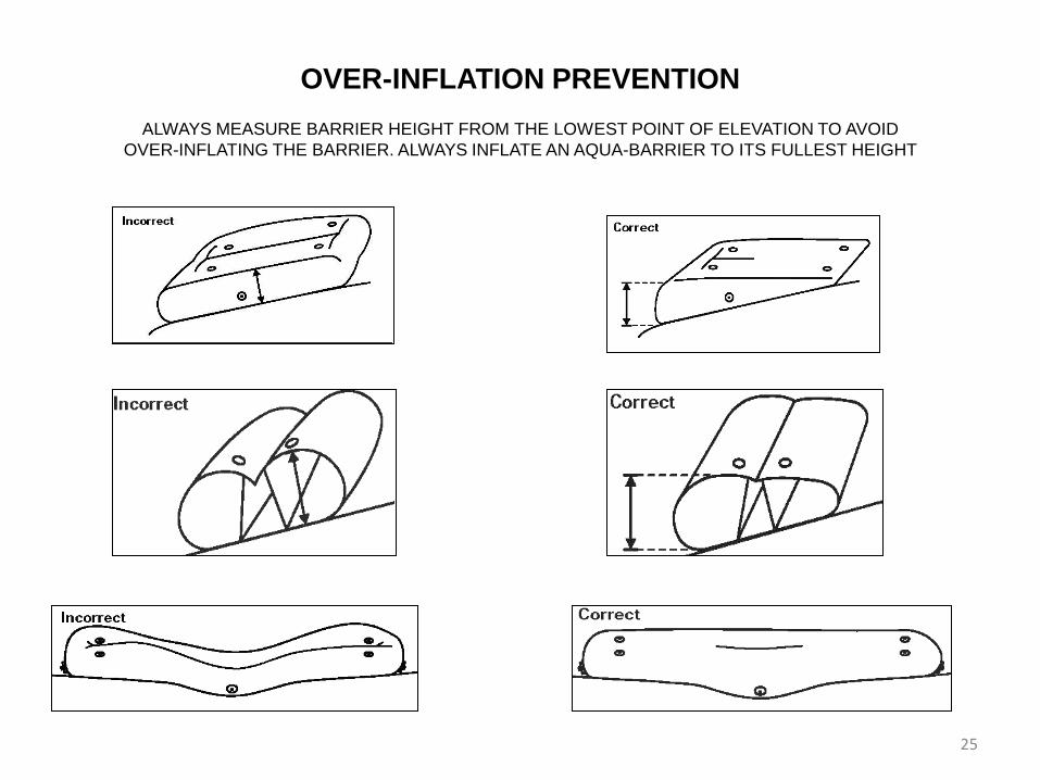
OVER-INFLATION PREVENTION ALWAYS MEASURE BARRIER HEIGHT FROM THE LOWEST POINT OF ELEVATION TO AVOID
OVER-INFLATING THE BARRIER. ALWAYS INFLATE AN AQUA-BARRIER TO ITS FULLEST HEIGHT
25

INSTALLATION PROCEDURE There are three primary types of Aqua Barrier installations. The following descriptions of the various types of installations are simplified, and are only meant to give a general overview of the installation process. More detailed installation information must be provided by a trained Hydrological Solutions representative on all Aqua-Barrier installations. During all Aqua-Barrier installations the barriers can tractor or rotate toward the side which possesses less hydrostatic pressure or water depth. The maximum length of movement toward the side of least water resistance is 1/2 of the properly inflated barrier height (i.e.,6 ft high barrier can adjust as much as 3 ft).The same adjustment behavior can occur if a slope or grade exists from one side of a barrier to the other. Barriers which are not inflated to their proper height can tractor toward the dewatered area more than 1/2 of the recommended inflated height. (See Baffle Behavior page 5) Dry surface installation: The location where the barriers are to be installed has no water present. The barriers are simply unrolled and in inflated. This style of installation is generally used in anticipation of flood waters. Static water installation: Non-moving water is present at installation location. The barriers are buoyant and float on the waters surface. The barriers are placed at the waters edge, unrolled on the waters surface and floated into position. Dynamic water installations: Dynamic or moving water is present at installation location. Barriers are positioned properly by controlling the ends of the unit with hydraulic equipment (i.e. track hoe, crane) and/or anchoring at least one end of the barrier at the shoreline.
26

DEPLOYMENT USING 1 TRACK HOE AND SHORELINE ANCHOR
27

DEPLOYMENT USING 2
TRACK HOES
28
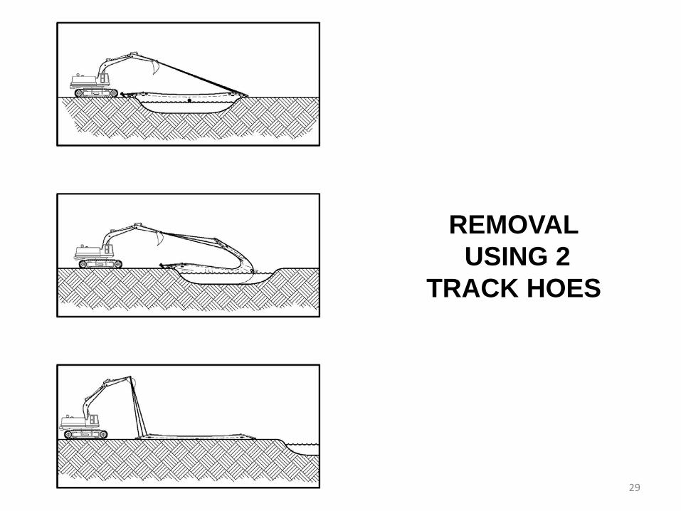
REMOVAL USING 2
TRACK HOES
29

MANUAL DEPLOYMENT
30

MANUAL DEPLOYMENT
POSTION THE FIRST BARIER IN PLACE, INFLATE TO WITHIN 1 FOOT OF ITS FULLEST HEIGHT BRING THE NEXT BARRIER ON TOP, MAKING SURE TO APPLY THE CORRECT AMOUNT OF OVERLAP AS SHOWN ON THE CHART, PAGE 19 INFLATE THIS BARRIER TO WITHIN 1 FOOT OF ITS HEIGHT CONTINUE UNTIL ALL BARRIERS ARE IN PLACE THE LAST BARRIER (ON TOP) SHOULD BE FULLY INFLATED. MAKING SURE TO MEASURE BARRIER HEIGHT FROM THE LOWEST ELEVATION TOP OFF ALL BARRIERS TO THEIR FULLEST HEIGHT IT IS NECESSARY FOR ALL AQUA-BARRIERS TO BE FULLY INFLATED THROUGHOUT THE DURATION OF THE PROJECT
31
REMOVAL PROCEDURE There are three primary types of Aqua-Barrier removal procedures. The following descriptions of the various types of Aqua-Barrier removal procedures are simplified and are only meant to give a general overview of the removal process. More detailed removal procedure information must be provided by a trained Hydrological Solutions, Inc. representative on all Aqua-Barrier removals. Dry surface removal When no water is present on either side of the Aqua-Barriers: Locate all drain ports along the sides and ends of the barrier and remove all plugs. After the majority of the water has drained from the barrier you will be able to force the remaining water toward a drain port by pushing on the barrier with your hands. Evacuate all water. Fold and the roll the barrier to fit on the pallet it arrived on making sure no part is hanging off the pallet. Standing water removal When standing water is present on one side of the barrier only: First attach one end of the barrier to the hydraulic equipment arm (ie: track hoe, crane). Water must be equalized on both sides of the Aqua-Barrier prior to removing it from the water. Locate the drain ports on the dry side of the barrier only and remove all plugs. Once the majority of the water has drain from the barrier you can remove the plugs on the opposite side of the barrier. You can now pull one end of the barrier over the top and down the length of the barrier. This process will evacuate the remaining water and prevent cuts and abrasions on the bottom of the unit. Fold and the roll the barrier to fit on the pallet it arrived on making sure no part is hanging off the pallet. Moving water removal When moving water is present on one side of the barrier only: First attach both ends of the barrier to the hydraulic equipment arm (ie: track hoe, crane). Water must be equalized on both sides of the Aqua-Barrier prior to removing it from the water. Both ends of the Aqua-Barrier must have attached pipes controlled by hydraulic equipment arm (i.e. track hoe, crane). Locate the drain ports on the dry side of the barrier only and remove all plugs. Once the majority of the water has drain from the barrier you can remove the plugs on the opposite side of the barrier. You can now pull one end of the barrier over the top and down the length of the barrier. This process will evacuate the remaining water and prevent cuts and abrasions on the bottom of the unit. Fold and the roll the barrier to fit on the pallet it arrived on making sure no part is hanging off the pallet.
32
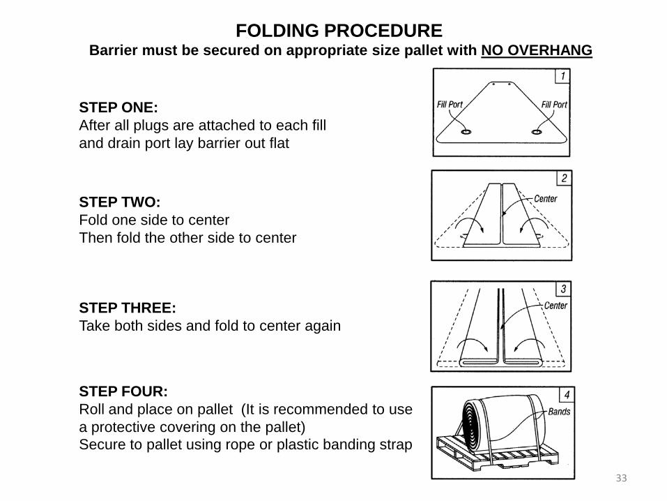
FOLDING PROCEDURE
Barrier must be secured on appropriate size pallet with NO OVERHANG
STEP ONE: After all plugs are attached to each fill and drain port lay barrier out flat
STEP TWO: Fold one side to center Then fold the other side to center
STEP THREE: Take both sides and fold to center again
STEP FOUR: Roll and place on pallet (It is recommended to use a protective covering on the pallet) Secure to pallet using rope or plastic banding strap
33
REPAIR INSTRUCTIONS
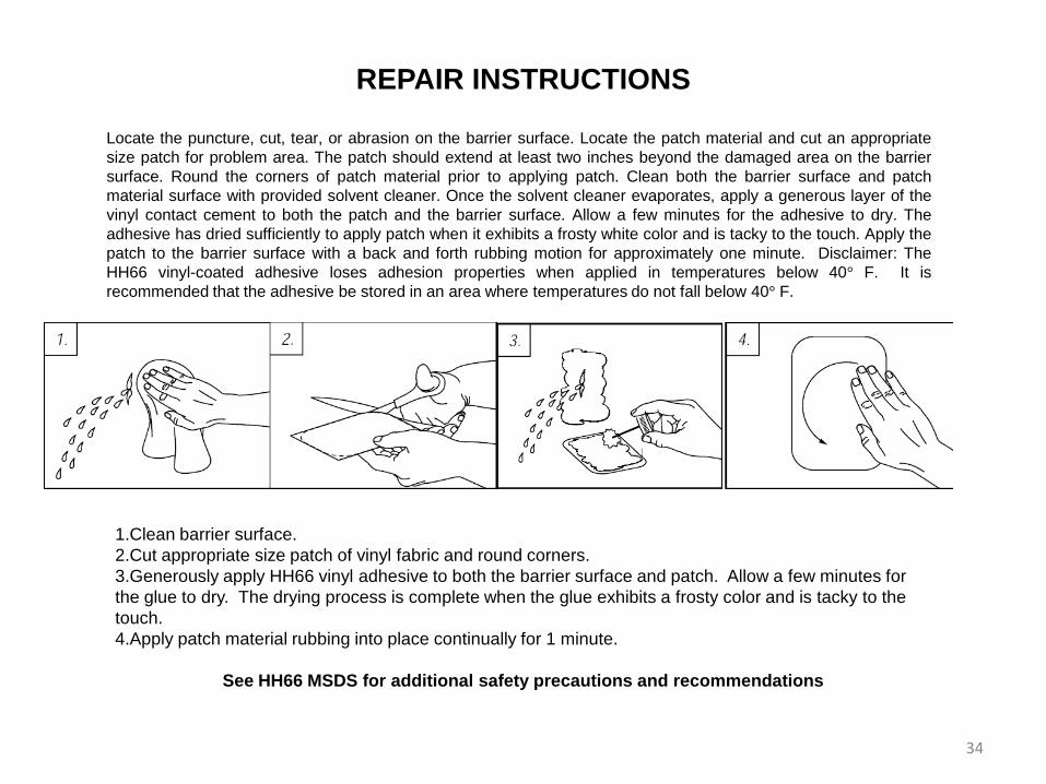
Locate the puncture, cut, tear, or abrasion on the barrier surface. Locate the patch material and cut an appropriate size patch for problem area. The patch should extend at least two inches beyond the damaged area on the barrier surface. Round the corners of patch material prior to applying patch. Clean both the barrier surface and patch material surface with provided solvent cleaner. Once the solvent cleaner evaporates, apply a generous layer of the vinyl contact cement to both the patch and the barrier surface. Allow a few minutes for the adhesive to dry. The adhesive has dried sufficiently to apply patch when it exhibits a frosty white color and is tacky to the touch. Apply the patch to the barrier surface with a back and forth rubbing motion for approximately one minute. Disclaimer: The HH66 vinyl-coated adhesive loses adhesion properties when applied in temperatures below 40° F. It is recommended that the adhesive be stored in an area where temperatures do not fall below 40° F.
1.Clean barrier surface. 2.Cut appropriate size patch of vinyl fabric and round corners. 3.Generously apply HH66 vinyl adhesive to both the barrier surface and patch. Allow a few minutes for the glue to dry. The drying process is complete when the glue exhibits a frosty color and is tacky to the touch. 4.Apply patch material rubbing into place continually for 1 minute.
See HH66 MSDS for additional safety precautions and recommendations
34

MAINTENANCE: To maintain Aqua-Barriers simply repair worn and punctured areas with the available repair material. Repairing is best accomplished when the barrier surface has been cleaned. Follow the repair instructions provided in this manual or on the can of Vinyl adhesive HH66. If additional repair adhesive is needed, call R H Products at 781-259-9464 to locate the nearest distributor. It is recommended that the Aqua-Barriers be inflated with air in order to inspect for problem areas, and repair as needed. Always allow the barrier surface to dry before tightly rolling up for storage. STORAGE: Store Aqua-Barriers in a covered area, away from harmful UV rays. Do not store where barriers will be in contact with solvents, acids or rodents. Do not store in an area that experiences temperatures that fall below 32° F or above 150° F. DEFINITIONS: Dynamic Load – Water pressure created by moving water and/or wave action. Free Board – part or height of barrier extending above water surface Hydrostatic Pressure – Water pressure Static Load – Water pressure created by standing or non-moving water PVC – Vinyl Coated Polyester. Material used to produce Aqua-Barriers
MAINTENANCE * STORAGE * DEFINITIONS
35

Test Method Unit KPF-30
Total Weight ASTM D-3776 oz / sq.yd 30
Coating PVC
Base Fabric Denier
Polyester 1500D
Base Fabric Weight oz / sq.yd 12
Vinyl Weight oz / sq.yd 18
Surface Matt
Tensile Strength ASTM D 751 lbs. / inch 700X650(±30)
Tear Strength ASTM D 751 lbs. 170 X 140(±20)
Adhesion ASTM D 751 lbs. / inch 20 X 17(±2)
UV Resistance Ultra Violet Protected
Cold Crack MIL-C-20696 °F -22
Color Fastness to Light ISO105 B02:2000 Xenon-Arc.-Lamp Grade Above 5
Available Width inch 61.5
Standard Roll Length yd / roll 50
Remark
Aqua-Barrier Material Specifications Technical Characteristics
36

Statement of Limited Warranty A. General. This warranty is intended solely for the benefit of the original (retail) purchaser (“Purchaser”) of the products (“the Products”) supplied by Hydrological Solutions, Inc./DA Miller Associates, LLC This warranty is effective only in the United States of America. B. Limited Warranty. Hydrological Solutions/DA Miller warrants its products against manufacturing defects for 90 days from the date of the original purchase of the Products. The Aqua-Barriers and all parts and accessories associated with them are warranted for only the purchaser’s first installation, which is the inflation, draining, and repositioning, or site removal, of the Aqua-Barrier. After an Aqua-Barrier has been partially or completely drained, repositioned, or removed from the initial installation location, no stated or implied warranty or product protection shall apply. The Company’s responsibility for defects in the Products is limited to the Company’s choice of repair, or replacement. This warranty gives purchasers of the Products specific rights, and such purchasers may also have other rights that vary from state to state. This warranty shall be effective only if the Products manufactured by the Company have not been subjected to negligent use, misuse, or abuse (including any usage not in accordance with the Product instructions, or failure to perform the required preventive maintenance). This warranty is limited to the cost of the manufactured Products that are found to be defective. No agent, employee, or officer of the Company, or any other person, is authorized to give any other warranty, or to assume any other liability on behalf of the Company. Hydrological Solutions, Inc./DA Miller Associates, LLC is not responsible for barrier replacement or repair if static water levels exceed 75% of the proper barrier inflation height, i.e. 4.5 ft water level on a 6ft high properly inflated Aqua-Barrier. In moving water environments, or potentially moving water environments, Hydrological Solutions, Inc./DA Miller Associates, LLC will designate a maximum water percentage height on a given barrier height. If water levels exceed either of these limitations, this warranty shall be null and void. Aqua-Barriers are not warranted in moving water environments unless a Hydrological Solutions agent or representative is on site to monitor the project from commencement to end. A moving body of water shall be defined as any body of water that exhibits movement or any static body of water that becomes dynamic (i.e. rainfall runoff, water released by a dam, etc). THE COMPANY SHALL NOT BE LIABLE FOR ANY INDIRECT, SPECIAL, OR CONSEQUENTIAL DAMAGES OF ANY NATURE WHATSOEVER, WHETHER TO THE PRUCHASER OF THE PRODUCTS, OR TO THIRD PARTIES, IN TORT, CONTRACT, OR OTHERWISE (some States do not allow the exclusion or limitation of incidental or consequential damages, so the preceding limitation or exclusion may not apply to all Purchasers). THE COMPANY ASSUMES NO REPSONSIBLITY OR LIABILITY, WHETHER EXPRESS OR IMPLIED, WHETHER IN TORT OR IN CONTRACT, AS TO THE CAPACITY OF ITS MANUFACTURED PRODUCTS TO SATISFY THE REQUIREMENT OF ANY LAW, RULE, SPECIFICAITON, OR CONTRACT PERTAINING THERETO, INCLUDING, BUT NOT LIMITED TO, ANY CONTRACT BETWEEN ANY PURCHASER OF ITS PRODUCTS AND CONTRACTING PARTIES WITH WHOM SUCH PURCHASER HAS CONTRACTED. THE WARRANTIES EXPRESSED HEREIN ARE IN LIEU OF ALL TORT LIABILITY AND ALL OTHER WARRANTIES OR REPRESENTATIONS, WHETHER EXPRESS OR IMPLIED, BY LAW OR BY CONTACT. THIS WARRANTY IS EXPRESSLY IN LIEU OF ANY OTHER WARRANTIES, EXPRESS, OR IMPLIED INCLUDING ANY IMPLIED WARRANTY OF MERCHANTABILITY OR PURPOSE, AND OF ANY OTHER OBLIGATION OR LIABILITY ON THE PART OF THE COMPANY (SOME STATES DO NOT ALLOW CERTAIN LIMITATIONS ON IMPLIED WARRANTIES, SO THE PRECEDING LIMITATION MAY NOT APPLY TO ALL PURCHASERS). •Repair and Replacement. As a condition precedent to any remedy described herein or otherwise available to Purchaser. Purchaser shall seek and accept the Company’s reasonable effort to repair or replace the allegedly defective or nonconforming Products (hereinafter “Affected Products: In furtherance of such undertaking, if Purchaser reasonable believes that (1) any Product contains a defect or nonconformity for which the Company is responsible; or (2) the Purchaser otherwise has a claim pursuant to the warranties contained herein, Purchaser shall inform the Company (in writing by completing a customer complaint form), of the nature of such defect, nonconformity, or claim in reasonable detail and shall request authorization from the Company to return the Affected Products to the Company for repair or replacement. All Products authorized for return shall be shipped prepaid to the Company’s facility or authorized service center at:
Hydrological Solutions, Inc./DA Miller Associates, LLC 41212 Park 290 Drive, Bldg D1
Waller, Tx 77484 1-800-245-0199
If the Company repairs or replaces the Affected Products within a reasonable time (normally six to eight weeks) after Purchaser has so returned them to the Company, Purchaser shall be entitled to no further remedy at law or equity. D. Certain Hazards Related to Products. Purchaser acknowledges that there are hazards associated with the use and storage of the Product(s) delivered hereunder, and Purchaser acknowledges that Purchaser understands and accepts such hazards. Purchaser shall be responsible for warning and protecting Purchaser’s employees and others who may be exposed to such hazards due to Purchaser’s storage and/or use of Product(s). Purchaser assumes all liability for loss, damage, or injury to persons or to property of Purchaser or others arising out of the delivery, presence or use of the Products whether used singly or in combination with other Products. 37