instruction manual for dodge sn2000 … · for dodge® sn2000 spherical roller bearings (metric and...
TRANSCRIPT
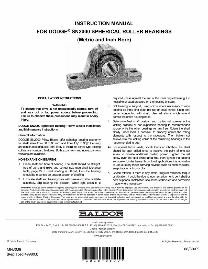
INSTRUCTION MANUAL FOR DODGE® SN2000 SPHERICAL ROLLER BEARINGS
(Metric and Inch Bore)
INSTALLATION INSTRUCTIONS
WARNING To ensure that drive is not unexpectedly started, turn off and lock out or tag power source before proceeding. Failure to observe these precautions may result in bodily injury.
DODGE SN2000 Spherical Bearing Pillow Blocks Installation and Maintenance Instructions
General Information DODGE SN2000 Pillow Blocks offer spherical bearing economy for shaft sizes from 30 to 90 mm and from 11/8" to 31/2". Housing are constructed of ductile iron. Easy to install set screw type locking collars are standard features. Both expansion and non-expansion versions are available.
NON-EXPANSION BEARING 1. Clean shaft and bore of bearing. The shaft should be straight,
free of burrs and nicks and correct size (see shaft tolerance table, page 2). If used shafting is utilized, then the bearing should be mounted on unworn section of shafting.
2. Lubricate shaft and bearing bore with grease or oil to facilitate assembly. Slip bearing into position. When light press fit is
required, press against the end of the inner ring of bearing. Do not strike or exert pressure on the housing or seals.
3. Bolt bearing to support, using shims where necessary to align bearing so inner ring does not rub on seal carrier. Keep seal carrier concentric with shaft. Use full shims which extend across the entire housing base.
4. Determine final shaft position and tighten set screws in the locking collar(s) of non-expansion bearing to recommended torque while the other bearings remain free. Rotate the shaft slowly under load, if possible, to properly center the rolling elements with respect to the raceways. Then tighten set screws into the locking collar of the remaining bearings to the recommended torque.
4a. For normal thrust loads, shock loads or vibration, the shaft should be spot drilled once to receive the point of one set screw to provide additional holding power. Tighten the set screw over the spot drilled area first, then tighten the second set screw. Under heavy thrust load applications it is advisable to use auxiliary thrust carrying devices such as shaft shoulder, snap rings or a thrust collar.
5. Check rotation. If there is any strain, irregular rotational torque or vibration, it could be due to incorrect alignment, bent shaft or bent supports. Installation should be rechecked and correction made where necessary.
WARNING: Because of the possible danger to persons(s) or property from accidents which may result from the improper use of products, it is important that correct procedures be followed. Products must be used in accordance with the engineering information specified in the catalog. Proper installation, maintenance and operation procedures must be observed. The instructions in the instruction manua’s must be followed. Inspections should be made as necessary to assure safe operation under prevailing conditions. Proper guards and other suitable safety devices or procedures as may be desirable or as may be specified in safety codes should be provided, and are neither provided by Baldor Electric Company nor are the responsibility of Baldor Electric Company. This unit and its associated equipment must be installed, adjusted and maintained by qualified personnel who are familiar with the construction and operation of all equipment in the system and the potential hazards involved. When risk to persons or properly may be involved, a failsafe device must be an integral part of the driven equipment beyond the speed reducer output shaft.
World HeadquartersP.O. Box 2400, Fort Smith, AR 72902-2400 U.S.A., Ph: (1) 479.646.4711, Fax (1) 479.648.5792, International Fax (1) 479.648.5895
Dodge Product Support6040 Ponders Court, Greenville, SC 29615-4617 U.S.A., Ph: (1) 864.297.4800, Fax: (1) 864.281.2433
www.baldor.com
© Baldor Electric Company All Rights Reserved. Printed in USA.
MN3038(Replaced 499803)
06/30/09
*3038-0609*
2
EXPANSION BEARINGSteps (1, 2, 3) Same as Non-Expansion Bearing. 4. Position expansion bearing in the housing. For normal
expansion conditions, the bearing insert should be positioned in the center of the housing. To center bearing insert in housing, move bearing insert to extreme position and mark shaft. Then using bearing maximum total expansion table, move bearing insert in opposite direction one-half the total expansion to center bearing in the housing. If maximum expansion is required, move bearing insert to the extreme position in the housing to permit full movement in direction of expansion. After expansion bearing has been positioned in the housing, tighten the set screws in the locking collar to the recommended torque.
5. Same as Non-Expansion Bearing. FIELD CONVERSION (RE-OP) OF A NON-EXPANSION BEARING INTO AN EXPANSION BEARING All SN2000 non-expansion bearings can be re-oped to become an expansion bearing. To modify a non-expansion to an expansion bearing: (1) remove bearing collar. (2) Remove snap ring from collar side of bearing and also remove the non-expansion spacer. (3) Reinstall snap ring. (4) Press, not hammer, on inner ring end opposite the collar and install bearing per Expansion Bearing instruction. Note: Bearing name plate has a non-expansion Part Number. When bearing is modified, bearing should be marked as expansion for future reference.
Bearing Maximum Total Expansion Table
Shaft Size Total Expansion MM Inch MM Inch
30–35 11/8–11/2 3.18 .125 40–90 15/8–31/2 6.35 .250
LUBRICATION INSTRUCTIONSOPERATION IN PRESENCE OF DUST, WATER OR CORROSION VAPORS This bearing is factory lubricated with a No. 2 consistency lithium-base grease with ISO 100 oil which is suitable for most applications. However, extra protection is necessary if bearing is subjected to excessive moisture, dust or corrosive vapor. In these cases, bearing should contain as much grease as speed will permit (a full bearing with consequent slight leakage through the seal is the best protection against contaminant entry). In extremely dirty environments, the bearing should be purged daily to flush out contaminants. For added protection, it is advisable to shroud the bearing from falling material.
HIGH SPEED OPERATION At higher operating speeds, too much grease may cause overheating. In these cases, the amount of lubrication can only be determined by experience. If excess grease causes overheating, remove grease fittings and run for ten minutes. This will allow excess grease to escape. Then wipe off excess grease and replace grease fittings. In higher speed applications, a small amount of grease at frequent intervals is preferable to a large amount at
infrequent intervals. However, the proper volume and interval of lubrication can best be determined by experience.
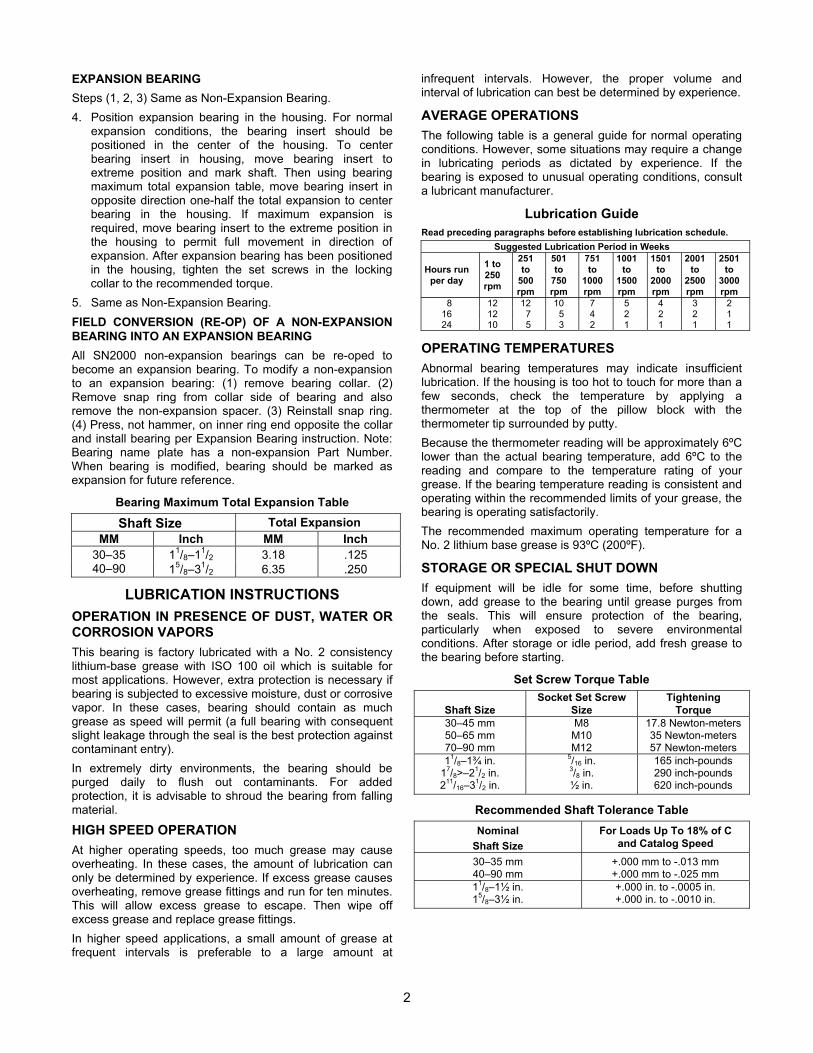
AVERAGE OPERATIONS The following table is a general guide for normal operating conditions. However, some situations may require a change in lubricating periods as dictated by experience. If the bearing is exposed to unusual operating conditions, consult a lubricant manufacturer.
Lubrication Guide Read preceding paragraphs before establishing lubrication schedule.
Suggested Lubrication Period in Weeks
Hours run per day
1 to 250rpm
251to
500rpm
501to
750rpm
751to
1000rpm
1001to
1500rpm
1501to
2000rpm
2001to
2500rpm
2501to
3000rpm
8 12 12 10 7 5 4 3 2 16 12 7 5 4 2 2 2 1 24 10 5 3 2 1 1 1 1
OPERATING TEMPERATURESAbnormal bearing temperatures may indicate insufficient lubrication. If the housing is too hot to touch for more than a few seconds, check the temperature by applying a thermometer at the top of the pillow block with the thermometer tip surrounded by putty. Because the thermometer reading will be approximately 6ºC lower than the actual bearing temperature, add 6ºC to the reading and compare to the temperature rating of your grease. If the bearing temperature reading is consistent and operating within the recommended limits of your grease, the bearing is operating satisfactorily. The recommended maximum operating temperature for a No. 2 lithium base grease is 93ºC (200ºF).
STORAGE OR SPECIAL SHUT DOWN If equipment will be idle for some time, before shutting down, add grease to the bearing until grease purges from the seals. This will ensure protection of the bearing, particularly when exposed to severe environmental conditions. After storage or idle period, add fresh grease to the bearing before starting.
Set Screw Torque Table
Shaft SizeSocket Set Screw
SizeTightening
Torque30–45 mm M8 17.8 Newton-meters 50–65 mm M10 35 Newton-meters 70–90 mm M12 57 Newton-meters 11/8–1¾ in. 5/16 in. 165 inch-pounds
17/8>–21/2 in. 3/8 in. 290 inch-pounds 211/16–31/2 in. ½ in. 620 inch-pounds
Recommended Shaft Tolerance Table Nominal
Shaft SizeFor Loads Up To 18% of C
and Catalog Speed30–35 mm +.000 mm to -.013 mm 40–90 mm +.000 mm to -.025 mm 11/8–1½ in. +.000 in. to -.0005 in. 15/8–3½ in. +.000 in. to -.0010 in.
3
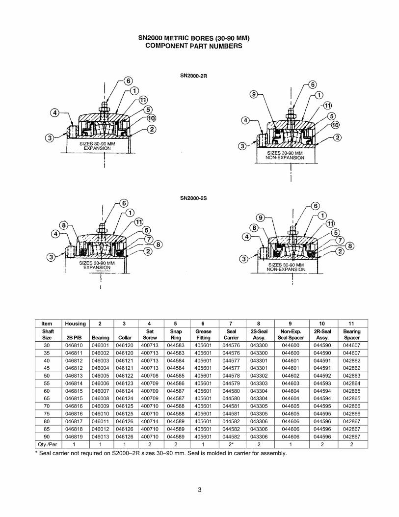
Item Housing 2 3 4 5 6 7 8 9 10 11 Shaft Size 2B P/B Bearing Collar
SetScrew
SnapRing
GreaseFitting
SealCarrier
2S-Seal Assy.
Non-Exp.Seal Spacer
2R-Seal Assy.
BearingSpacer
30 046810 046001 046120 400713 044583 405601 044576 043300 044600 044590 044607 35 046811 046002 046120 400713 044583 405601 044576 043300 044600 044590 044607 40 046812 046003 046121 400713 044584 405601 044577 043301 044601 044591 042862 45 046812 046004 046121 400713 044584 405601 044577 043301 044601 044591 042862 50 046813 046005 046122 400708 044585 405601 044578 043302 044602 044592 042863 55 046814 046006 046123 400709 044586 405601 044579 043303 044603 044593 042864 60 046815 046007 046124 400709 044587 405601 044580 043304 044604 044594 042865 65 046815 046008 046124 400709 044587 405601 044580 043304 044604 044594 042865 70 046816 046009 046125 400710 044588 405601 044581 043305 044605 044595 042866 75 046816 046010 046125 400710 044588 405601 044581 043305 044605 044595 042866 80 046817 046011 046126 400714 044589 405601 044582 043306 044606 044596 042867 85 046818 046012 046126 400710 044589 405601 044582 043306 044606 044596 042867 90 046819 046013 046126 400710 044589 405601 044582 043306 044606 044596 042867
Qty./Per 1 1 1 2 2 1 2* 2 1 2 2
* Seal carrier not required on S2000–2R sizes 30–90 mm. Seal is molded in carrier for assembly.
4
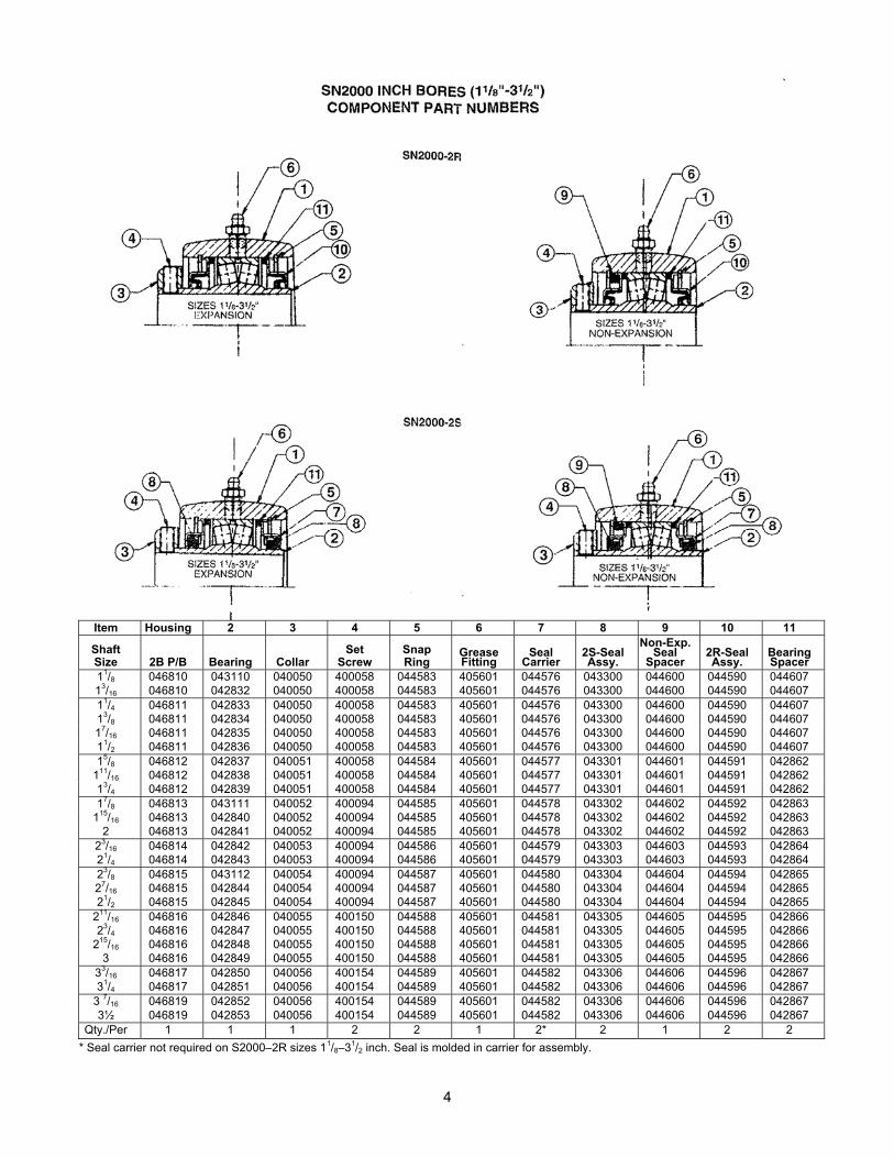
Item Housing 2 3 4 5 6 7 8 9 10 11
ShaftSize 2B P/B Bearing Collar
SetScrew
SnapRing
GreaseFitting
SealCarrier
2S-SealAssy.
Non-Exp. Seal
Spacer2R-SealAssy.
BearingSpacer
11/8 046810 043110 040050 400058 044583 405601 044576 043300 044600 044590 044607 13/16 046810 042832 040050 400058 044583 405601 044576 043300 044600 044590 044607 11/4 046811 042833 040050 400058 044583 405601 044576 043300 044600 044590 044607 13/8 046811 042834 040050 400058 044583 405601 044576 043300 044600 044590 044607 17/16 046811 042835 040050 400058 044583 405601 044576 043300 044600 044590 044607 11/2 046811 042836 040050 400058 044583 405601 044576 043300 044600 044590 044607 15/8 046812 042837 040051 400058 044584 405601 044577 043301 044601 044591 042862
111/16 046812 042838 040051 400058 044584 405601 044577 043301 044601 044591 042862 13/4 046812 042839 040051 400058 044584 405601 044577 043301 044601 044591 042862 17/8 046813 043111 040052 400094 044585 405601 044578 043302 044602 044592 042863
115/16 046813 042840 040052 400094 044585 405601 044578 043302 044602 044592 042863 2 046813 042841 040052 400094 044585 405601 044578 043302 044602 044592 042863
23/16 046814 042842 040053 400094 044586 405601 044579 043303 044603 044593 042864 21/4 046814 042843 040053 400094 044586 405601 044579 043303 044603 044593 042864 23/8 046815 043112 040054 400094 044587 405601 044580 043304 044604 044594 042865 27/16 046815 042844 040054 400094 044587 405601 044580 043304 044604 044594 042865 21/2 046815 042845 040054 400094 044587 405601 044580 043304 044604 044594 042865
211/16 046816 042846 040055 400150 044588 405601 044581 043305 044605 044595 042866 23/4 046816 042847 040055 400150 044588 405601 044581 043305 044605 044595 042866
215/16 046816 042848 040055 400150 044588 405601 044581 043305 044605 044595 042866 3 046816 042849 040055 400150 044588 405601 044581 043305 044605 044595 042866
33/16 046817 042850 040056 400154 044589 405601 044582 043306 044606 044596 042867 31/4 046817 042851 040056 400154 044589 405601 044582 043306 044606 044596 042867
3 7/16 046819 042852 040056 400154 044589 405601 044582 043306 044606 044596 042867 3½ 046819 042853 040056 400154 044589 405601 044582 043306 044606 044596 042867
Qty./Per 1 1 1 2 2 1 2* 2 1 2 2 * Seal carrier not required on S2000–2R sizes 11/8–31/2 inch. Seal is molded in carrier for assembly.