instruction manual - fcc id search card ... data reset ... for you to make the best use of your...
TRANSCRIPT

1M23N32902
INSTRUCTION MANUAL
18-Channel Digital Proportional R/C System
TM
TM

INTRODUCTION............................................... 4●Support and Service ......................................... 4●Application, Export, and Modification ........... 5●Compliance Information Statement ............... 5●Definitions of Symbols ...................................... 7●Safety Precautions (do not operate without
reading) ............................................................. 7
BEFORE USE ................................................... 11●Features of T16SZ ......................................... 11●Contents and technical specifications ........... 12●Multicopter/Robot specifications .................. 12●Accessories ....................................................... 13●Transmitter controls ....................................... 14●Transmitter's antenna .................................... 15●Switch (SA-SH) ............................................... 16●Volume (LD, RD) ............................................ 17●Slide Lever ....................................................... 17●Digital Trims (T1-T4) ..................................... 18●Transmitter NiMH Battery HT5F1800B ...... 19●How to turn transmitter power ON/OFF ..... 21●Touch Panel ..................................................... 22●HOME/EXIT and U.MENU/MON. .............. 22●Panel lock ........................................................ 23●RF off mode ..................................................... 23●Monitor LED display...................................... 24●Stick control .................................................... 24
Stick control (Airplane Example) ................. 25Stick control (Helicopter Example) .............. 26Stick control (Multicopter Example) ............ 27
●Stick Adjustment ............................................ 28●SD card ............................................................ 29●Connector/Plug ............................................... 31●Receiver nomenclature ................................... 32●Receiver's antenna installation ...................... 34●Safety precautions when installing servos ... 35●S.BUS/S.BUS2 Installation ............................ 36●S.BUS Wiring example ................................... 37
●S.BUS2 System ................................................ 38●S.BUS/S.BUS2 device setting ......................... 39
BASIC OPERATION ....................................... 40●Home screen .................................................... 40●Link procedure .............................................. 41●After setting ..................................................... 42●If the receiver's voltage does not display on
the transmitter ............................................... 43●Range testing your R/C system...................... 44
Model Basic Setting Procedure ........................ 45Airplane ........................................................... 45Helicopter ........................................................ 47Servos connection by model type .................. 50
SYSTEM MENU ............................................... 56Display ............................................................. 57Sound volume ................................................. 58Date and Time................................................. 58H/W setting ..................................................... 59Battery ............................................................. 60Range check .........................................60(→44)S.Bus servo ..................................................... 61Information .................................................... 64
LINKAGE MENU ............................................ 65Servo monitor ................................................. 66Model select .................................................... 67Model type ...................................................... 70Servo reverse ................................................... 72End point ......................................................... 73Servo speed ..................................................... 74Sub-trim .......................................................... 74Function .......................................................... 75Fail safe ........................................................... 77System type ..................................................... 78Trim setting .................................................... 80Throttle cut ..................................................... 81
TABLE OF CONTENTS

TABLE OF CONTENTS
Idle down ......................................................... 82Swash ring (Heli only) .................................... 83Swash (Heli only, except H-1) ........................ 84Stick alarm ...................................................... 86Timer ............................................................... 87Function name ................................................ 88Telemetry system ............................................ 89Sensor .............................................................. 91Telemetry......................................................... 94Telemetry:Receiver [Battery] ........................ 95Telemetry:Receiver [Ext-batt]....................... 96Telemetry:Temperature ................................. 97Telemetry:RPM sensor .................................. 98Telemetry:Altitude ......................................... 99Telemetry:Altitude [Variometer] ................ 100Telemetry:Voltage [Battery] ........................ 103Telemetry:Voltage [Ext-batt] ....................... 104Telemetry:GPS [Distance] ........................... 105Telemetry:GPS [Speed]................................ 107Telemetry:GPS [Altitude, Variometer, Position] 108Telemetry:Servo sensor [Current] .............. 109Telemetry:Servo sensor [Temperature, Angle] 110Telemetry:Current sensor [Current] ...........111Tele. setting (Telemetry setting) .................. 112Trainer ........................................................... 114Warning setting ............................................ 117User menu setting ......................................... 118Data reset ...................................................... 119
MODEL MENU (Common functions) .......... 120Condition select ........................................... 121AFR .............................................................. 123Dual rate ........................................................ 124Prog, mixes (Program mixing) .................... 125
MODEL MENU (Airplane/Glider/Multicopter)Aileron differential. ...................................... 129Flap setting .................................................... 130AIL → Camber flap ...................................... 131AIL → Brake flap ......................................... 132Aileron → Rudder ........................................ 133
Elevator → Camber ..................................... 134Camber mixing ............................................. 135Airbrake → ELE .......................................... 137Camber flap → ELE ..................................... 138Rudder → Aileron ........................................ 139Rudder → Elevator ...................................... 140Butterfly ........................................................ 141Trim mix 1/2 .................................................. 143Snap roll (Airplane only) ............................. 144Air brake (Airplane only) ............................ 145Gyro .............................................................. 146Ailevator ........................................................ 148Acceleration .................................................. 149Motor ............................................................. 150V-tail .............................................................. 151Winglet .......................................................... 152
MODEL MENU (Helicopter)Pitch curve .................................................... 154Throttle curve ............................................... 157Acceleration .................................................. 159Throttle hold ................................................. 160Swash mixing ................................................ 161Throttle mixing ............................................. 162Pitch → Needle.............................................. 163Pitch → Rudder (Revolution mixing) ......... 164Gyro (Helicopter) ......................................... 165Governor ....................................................... 167
Common Operations used in function setup screen ................................................................ 169●Operations value setting ............................... 169●Operations related to flight conditions ....... 169●Operations related to fine tuning VR .......... 170●Operations related to servo speed ............... 171●Curve setting operation ................................ 172●Switch selection method ............................... 177●Updating ........................................................ 181●T14SG/FX-22 ⇒ T16SZ DATA ................... 183
4 < Introduction >
Thank you for purchasing a Futaba® FASSTest-2.4GHz* T16SZ series digital proportional R/C system. This system is extremely versatile and may be used by beginners and pros alike. In order for you to make the best use of your system and to fly safely, please read this manual carefully. If you have any difficulties while using your system, please consult the manual, our online Frequently Asked Questions (on the web pages referenced below), your hobby dealer, or the Futaba Service Center.
*FASSTest: Futaba Advanced Spread Spectrum Technology extend system telemetry
Due to unforeseen changes in production procedures, the information contained in this manual is subject to change without notice.
Support and Service: It is recommended to have your Futaba equipment serviced annually during your hobby’s “off season” to ensure safe operation.
In North America Please feel free to contact the Futaba Service Center for assistance in operation, use and programming. Please be sure to regularly visit the T16SZ Frequently Asked Questions web site at www.futaba-rc.com/faq/. This page includes extensive programming, use, set up and safety information on the T16SZ radio system and is updated regularly. Any technical updates and US manual corrections will be available on this web page. If you do not find the answers to your questions there, please see the end of our F.A.Q. area for information on contacting us via email for the most rapid and convenient response. Don’t have Internet access? Internet access is available at no charge at most public libraries, schools, and other public resources. We find internet support to be a fabulous reference for many modelers as items can be printed and saved for future reference, and can be accessed at any hour of the day, night, weekend or holiday. If you do not wish to access the internet for information, however, don’t worry. Our support teams are available Monday through Friday 8-5 Central time to assist you.
For Service Only: Futaba Service Center
3002 N. Apollo Drive, Suite 1Champaign, IL 61822 Phone: 217-398-0007
www.futaba-rc.com/service.htmlEmail: [email protected]
For Support : (Programming and user questions)
Please start here for answers to most questions: www.futaba-rc.com/faq/
Fax: 217-398-7721 Phone: 217-398-8970 option 2
Outside North America Please contact your Futaba importer in your region of the world to assist you with any questions, problems or service needs. Please recognize that all information in this manual, and all support availability, is based upon the systems sold in North America only. Products purchased elsewhere may vary. Always contact your region’s support center for assistance.
INTRODUCTION

5< Introduction >
Compliance Information Statement This device complies with part 15 of the FCC Rules. Operation is subject to the following two conditions:(1) This device may not cause harmful interference, and (2) This device must accept any interference received, including interference that may cause undesired operation. RF Radiation Exposure Statement This equipment complies with FCC radiation exposure limits set forth for an uncontrolled environment.This transmitter must not be co-located or operating in conjunction with any other antenna or transmitter.The responsible party for the compliance of this device is:Futaba Service Center3002 N Apollo Drive Suite 1, Champaign, IL 61822 U.S.A.TEL (217)398-8970 or E-mail: [email protected] (Support)TEL (217)398-0007 or E-mail: [email protected] (Service)
The RBRC. SEAL on the nickel-cadmium battery contained in Futaba products indicates that Futaba Corporation is voluntarily participating in an industry-wide program to collect and recycle these batteries at the end of their useful lives, when taken out of service within the United States. The RBRC. program provides a convenient alternative to placing used nickel-cadmium batteries into the trash or municipal waste system, which is illegal in some areas.
(for USA) You may contact your local recycling center for information on where to return the spent battery. Please call 1-800-8BATTERY for information on NiCd battery recycling in your area. Futaba Corporation involvement in this program is part of its commitment to protecting our environment and conserving natural resources. *RBRC is a trademark of the Rechargeable Battery Recycling Corporation.
Application, Export, and Modification 1. This product may be used for unmanned aerial vehicle use. It is not intended for use in any application other than unmanned aerial vehicle control. The product is subject to regulations of the Ministry of Radio/Telecommunications and is restricted under Japanese law to such purposes. 2. Exportation precautions: (a) When this product is exported from the country of manufacture, its use is to be approved by the laws governing the country of destination which govern devices that emit radio frequencies. If this product is then re-exported to other countries, it may be subject to restrictions on such export. Prior approval of the appropriate government authorities may be required. If you have purchased this product from an exporter outside your country, and not the authorized Futaba distributor in your country, please contact the seller immediately to determine if such export regulations have been met. (b) Use of this product with anything other than models may be restricted by Export and Trade Control Regulations, and an application for export approval must be submitted. This equipment must not be utilized to operate equipment other than radio controlled models. 3. Modification, adjustment, and replacement of parts: Futaba is not responsible for unauthorized modification, adjustment, and replacement of parts on this product. Any such changes may void the warranty.
NOTE:This device complies with Industry Canada license-exempt RSS standard(s). Operation is subject to the following two conditions: (1) this device may not cause interference, and (2) this device must accept any interference, including interference that may cause undesired operation of the device. This equipment complies with IC radiation exposure limits set forth for an uncontrolled environment. This transmitter must not be co-located or operating in conjunction with any other antenna or transmitter.
French: Cet appareil radio est conforme au CNR-210 d’Industrie Canada. L’utilisation de ce dispositif est autorisée seulement aux deux conditions suivantes : (1) il ne doit pas produire de brouillage, et (2) l’utilisateur du dispositif doit être prêt à accepter tout brouillage radioélectrique reçu, même si ce brouillage est susceptible de compromettre le fonctionnement du dispositif. Cet équipement est conforme aux limites d’exposition aux rayonnements IC établies pour un environnement non contrôlé. Cet émetteur ne doit pas être co-situé ou fonctionner conjointement avec une autre antenne ou émetteur.

6 < Introduction >
Flying Safety Where to Fly We recommend that you fly at a recognized model airplane flying field. You can find model clubs and fields by asking your nearest hobby dealer, or, in the US, by contacting the Academy of Model Aeronautics. The national Academy of Model Aeronautics (AMA) has more than 2,500 chartered clubs across the country. Through any one of them, instructor training programs and insured newcomer training are available. Contact the AMA at the address or toll-free phone number below.
Academy of Model Aeronautics 5161 East Memorial Drive
Muncie, IN 47302Tele. (800) 435-9262Fax (765) 289-4248
or via the Internet at http:\\www.modelaircraft.org
Always pay particular attention to the flying field’s rules, as well as the presence and location of spectators, the wind direction, and any obstacles on the field. Be very careful flying in areas near power lines, tall buildings, or communication facilities as there may be radio interference in their vicinity.
CAUTION:To assure continued FCC compliance: Any changes or modifications not expressly approved by the grantee of this device could void the user's authority to operate the equipment.
This radio transmitter (IC: 2914D-T16SZ) has been approved by Industry Canada to operate with the antenna types listed below with the maximum permissible gain indicated. Antenna types not included in this list, having a gain greater than the maximum gain indicated for that type, are strictly prohibited for use with this device.
No. Name Gain(Peak) Remark1 ANTB18-186A0 2.14dBi 1/2λsleeve antenna
Federal Communications Commission Interference Statement (for U.S.A.)This equipment has been tested and found to comply with the limits for a Class B digital device,pursuant to Part 15 of the FCC Rules. These limits are designed to provide reasonable protection against harmful interference in a residential installation. This equipment generates, uses and can radiate radio frequency energy and, if not installed and used in accordance with the instructions, may cause harmful interference to radio communications. However, there is no guarantee that interference will not occur in a particular installation. If this equipment does cause harmful interference to radio or television reception, which can be determined by turning the equipment off and on, the user is encouraged to try to correct the interference by one or more of the following measures:--Reorient or relocate the receiving antenna.--Increase the separation between the equipment and receiver.--Connect the equipment into an outlet on a circuit different from that to which the receiver is connected.
--Consult the dealer or an experienced radio/TV technician for help.
CAUTION:To assure continued FCC compliance:Any changes or modifications not expressly approved by the grantee of this device could void the user’s authority to operate the equipment.

7< Introduction >
PrecautionsApplication, Export, and Modification Precautions.1. This product is only designed for use with radio control models. Use of the product described in this instruction
manual is limited to radio control models.2. Export precautions:
a) When this product is exported, it cannot be used where prohibited by the laws governing radio waves of the destination country.
b) Use of this product with other than models may be restricted by Export and Trade Control Regulations.3. Modification, adjustment, and parts replacement:
Futaba is not responsible for unauthorized modification, adjustment, or replacement of parts on this product.
■ No part of this manual may be reproduced in any form without prior permission.■ The contents of this manual are subject to change without prior notice.■ The contents of this manual should be complete, but if there are any unclear or missing parts please contact a
Futaba Service Center.■ Futaba is not responsible for the use of this product by the customer.■ Company and product names in this manual are trademarks or registered trademarks of the respective company.
For safe usePlease observe the following precautions to ensure safe use of this product at all times.Meaning of Special Markings: The parts of this manual indicated by the following marks require special attention from the standpoint of safety.
DANGER - Procedures which may lead to dangerous conditions and cause death/serious injury if not carried out properly.
WARNING - Procedures which may lead to a dangerous condition or cause death or serious injury to the user if not carried out properly, or procedures where the probability of superficial injury or physical damage is high.
CAUTION - Procedures where the possibility of serious injury to the user is small, but there is a danger of injury, or physical damage, if not carried out properly.
= Prohibited = Mandatory WARNING: Always keep electrical components away from small children.
Flying PrecautionsWARNING
Never grasp the transmitter antenna while flying.■ The transmitter output may drop drastically.
Always make sure that all transmitter stick movements operate all servos properly in the model prior to flight. Also, make sure that all switches, etc. function properly as well. If there are any difficulties, do not use the system until all inputs are functioning properly.
Never fly in range check mode. ■ In the dedicated range test range check mode, the
transmitter output range is reduced and may cause a crash.
While operating, never touch the transmitter with, or bring the transmitter near, another trans-mitter, a cellphone, or other wireless devices.■ Doing so may cause erroneous operation.
Do not point the antenna directly toward the aircraft during flight.
■ The antenna is directional and the transmitter output is weakest. (The strength of the radio waves is greatest from the sides of the antenna.)
Never fly on a rainy day, when the wind is strong, or at night. ■ Water could lead to failure or improper functionality
and poor control of the aircraft which could lead to a crash.
Never turn the power switch off during flight or while the engine or motor is running. ■ Operation will become impossible and the aircraft will
crash. Even if the power switch is turned on, operation will not begin until transmitter and receiver internal processing is complete.
Do not start the engine or motor while wearing the neck strap. ■ The neck strap may become entangled with the rotat-
ing propeller, rotor, etc. and cause a serious injury.
Do not fly when you are physically impaired as it could pose a safety hazard to yourself or others.

8 < Introduction >
Do not fly at the following places: ■ Near another radio control flying field.■ Near or above people.■ Near homes, schools, hospitals or other places where
people congregate.■ Near high voltage lines, high structures, or communi-
cation facilities.When setting the transmitter on the ground
during flight preparations, do not stand it upright.■ The transmitter may tip over, the sticks may move and
the propeller or rotor may rotate unexpectedly and cause injury. Do not touch the engine, motor, or ESC during
and immediately after use. ■ These items may become hot during use.
For safety, fly so that the aircraft is visible at all times. ■ Flying behind buildings or other large structures will
not only cause you to lose sight of the aircraft, but al-so degrade the RF link performance and cause loss of control.
From the standpoint of safety, always set the fail safe function. ■ In particular, normally set the throttle channel to idle.
For a helicopter, set the throttle channel to maintain a hover.
When flying, always return the transmitter set-up screen to the Home screen. ■ Erroneous input during flight is extremely dangerous.
Always check the remaining capacity of the transmitter and receiver batteries before each fly-ing session prior to flight. ■ Low battery capacity will cause loss of control and a
crash.
Always check operation of each control surface and perform a range test before each flying ses-sion. Also, when using the trainer function, check the operation of both the teacher and student transmitter. ■ Even one incorrect transmitter setting or aircraft abnor-
mality can cause a crash.
Before turning on the transmitter:1. Always move the transmitter throttle stick position to
the minimum (idle) position. 2. Turn on the transmitter first and then the receiver.
When turning off the transmitter's power switch after the engine or motor has stopped (state in which it will not rotate again):1. Turn off the receiver power switch. 2. Then turn off the transmitter power switch.■ If the power switch is turned on/off in the opposite or-
der, the propeller may rotate unexpectedly and cause a serious injury.
■ Also always observe the above order when setting the fail safe function.
■ Maximum low throttle: Direction in which the engine or motor runs at the slowest speed or stops.
When adjusting the transmitter, stop the engine except when necessary. In the case of a motor, disconnect the wiring that allows it to con-tinue operation. When doing so, please exercise extreme caution. Ensure that the aircraft is se-cured and that it will not come into contact with anything or anyone. Ensure that the motor will not rotate prior to making any adjustments. ■ Unexpected high speed rotation of the engine may
cause a serious injury.
Do not recharge a battery that is damaged, de-teriorated, leaking electrolyte, or wet.
Do not use the charger in applications other than as intended.
Do not allow the charger or battery to become wet. ■ Do not use the charger when it or your hands are wet.
Do not use the charger in humid places.
Do not short circuit the battery. Do not solder, repair, deform, modify, or disas-
semble the battery and/or battery charger. Do not drop the battery into a fire or bring it
near a fire.
Battery and Charger Handling PrecautionsDANGER
Do not charge and store the battery in direct sunlight or other hot places.
Do not charge the battery if it is covered with any object as it may become very hot.
Do not use the battery in a combustible envi-ronment. ■ The combustibles may could ignite ignite and cause an
explosion or fire.
Always charge the battery before each flying session. ■ If the battery goes dead during flight, the aircraft will
crash.
Charge the battery with the dedicated charger supplied with the set.

9< Introduction >
■ Charging the battery past the specified value may cause a fire, combustion, rupture, or liquid leakage. When quick charging, do not charge the battery above 1C.
■ Do not charge the battery while riding in a vehicle. Vi-bration will prevent normal charging.
Insert the power cord plug firmly into the receptacle up to its base.
Always use the charger with the specified power supply voltage.■ Use the special charger by connecting it to a proper
power outlet.
If the battery liquid should get in your eyes, do not rub your eyes, but immediately wash them with tap water or other clean water and get treat-ed by a doctor.■ The liquid can cause blindness.
Do not touch the charger and battery for any length of time during charging. ■ Doing so may result in burns.
Do not use a charger or battery that has been damaged.
Do not touch any of the internal components of the charger. ■ Doing so may cause electric shock or a burn.
If any abnormalities such as smoke or discolor-ation are noted with either the charger or the bat-tery, remove the battery from the transmitter or charger and disconnect the power cord plug and do not use the charger. ■ Continued use may cause fire, combustion, generation
of heat, or rupture.
Do not subject the batteries to impact.■ Doing so may cause fire, combustion, generation of
heat, rupture, or liquid leakage.
WARNING
Use and store the battery and battery charger in a secure location away from children. ■ Not doing so may cause electric shock or injury.
If the battery leaks liquid or generates an ab-normal odor, immediately move it to a safe place for disposal.■ Not doing so may cause combustion.
If the battery liquid gets on your skin or cloth-ing, immediately flush the area with tap water or other clean water.■ Consult a doctor. The liquid can cause skin damage.
After the specified charging time has elapsed, end charging and disconnect the charger from the receptacle.
When recycling or disposing of the battery, iso-late the terminals by covering them with tape.■ Short circuit of the terminals may cause combustion,
generation of heat or rupture.
Do not use the battery with devices other than the corresponding transmitter.
Do not place heavy objects on top of the bat-tery or charger. Also, do not place the battery or charger in any location where it may fall. ■ Doing so may cause damage or injury.
Do not store or use the battery and charger where it is dusty or humid. ■ Insert the power cord plug into the receptacle only af-
ter eliminating the dust.
After the transmitter has been used for a long time, the battery may become hot. Immediately remove it from the transmitter.
CAUTION■ Not doing so may cause a burn.
Do not charge the battery in extreme tempera-tures.■ Doing so will degrade the battery performance. An am-
bient temperature of 10℃ to 30℃ (50F to 86F) is ideal for charging.
Unplug the charger when not in use. Do not bend or pull the cord unreasonably and
do not place heavy objects on the cord.■ The power cord may be damaged and cause combus-
tion, generation of heat, or electric shock.

10 < Introduction >
Never disassemble or modify the SD card. Do not unreasonably bend, drop, scratch or
place heavy objects on the SD card.If smoke or an abnormal odor emanates from the
card, immediately turn off the transmitter power.
Since the SD card is an electronic device, be careful of static electricity. ■ Static electricity may cause erroneous operation or
trouble.
Do not use the SD card near radio and televi-sion sets, audio equipment, motors and other equipment that generate noise. ■ Doing so may cause erroneous operation.
Do not store the SD card in the following places:・ Where the humidity is high ・ Where the temperature difference is severe ・ Where it is very dusty ・ Where the card will be exposed to shock and vibration ・ Near speakers and other magnetic devices
SD Card (Commercial Product) Handling PrecautionsWARNING
CAUTION
*Read the instruction manual supplied with the SD card for details.
● Recorded dataThe data recorded on the SD card cannot be compensated regardless of the contents or cause of the trouble or obstruction. Futaba does not perform data restoration or recovery work.
Do not use the SD card where it may be ex-posed to water, chemicals, oil, or other fluids. ■ Doing so may cause a fire or electric shock by short cir-
cuiting.
Do not insert foreign matter into the transmit-ter card slot. ■ Doing so may cause erroneous operation.
Do not expose the card to shock and vibration and do not remove the card from the card slot while data is being written or read. ■ The data may be damaged or lost.
Keep wireless equipment, batteries, aircraft, etc. away from children.
Do not directly expose plastic parts to fuel, oil, exhaust gas, etc. ■ If left in such an environment, the plastic may be damaged. ■ Since the metal parts of the case may corrode, always
keep them clean.
Join the Academy of Model Aeronautics. ■ The Academy of Model Aeronautics (AMA) provides
guidelines and liability protection should the need arise.
Storage and Disposal Precautions
Other Precautions
WARNING
CAUTION
Do not store wireless devices in the following places: ・ Where it is extremely hot (40℃ [104F] or higher) or
cold (-10℃ [14F] or lower)・ Where the equipment will be exposed to direct sun-
light ・ Where the humidity is high ・ Where vibration is prevalent ・ Where it is very dusty ・ Where the device may be exposed to steam and heat
CAUTION
When the device will not be used for a long time, remove the battery from the transmitter and aircraft and store them in a dry place where the temperature is between 0 and 30℃ [32F and 86F].■ Leaving batteries inside your model and radio when
they are not being used for long periods will result in battery deterioration, liquid leakage and other damage.
Always use genuine Futaba products such as transmitter, receiver, servo, ESC, battery, etc.■ Futaba is not responsible for damage sustained by
combination with parts other than Futaba Genuine Parts. Use the parts specified in the instruction manual and catalog.

11< Before Use >
Features
FASSTest systemThe T16SZ transmitter has adopted the bidirectional communication system "FASSTest". Data from
the receiver can be checked in your transmitter. FASSTest is a maximum 18 channels 2.4GHz dedicated system.
Color touch screen LCDT16SZ has a HVGA 4.3inch full color Backlight LCD touch screen. The screen is manufactured of a
transflective construction which enables both indoor and outdoor visibility.
S.BUS2 systemBy using the S.BUS2 system multiple servos, gyros and telemetry sensors are easily installed with a
minimum amount of cables.
Model typesMulticopter. 8 swash types are available for helicopters. 7 types of main wings and 3 types of tail wings
are available for airplanes and gliders. Functions and mixing functions necessary for each model type are set in advance at the factory.
NiMH batteryT16SZ is operated by a 6.0 V/1,800 mAh NiMH battery.
SD card (Secure Digital memory card) (Not included)Model data can be saved to an SD card (SD:32MB-2GB SDHC:4GB-32GB). When T16SZ transmitter
software files are released, the software can be updated by using an SD card update.
Edit buttonTwo edit buttons are provided, and the operating screen can be immediately “Returned” to the HOME
screen during operation. Setting operation can be performed easily by combining this button with a touch sensor.
Vibration functionSelects a function that alerts the operator to various alarms by vibrating the transmitter in addition to
sounding a buzzer.
Speech functionA function is equipped which allows the system to provide telemetry data audibly. This function can
also be utilized with commercially available earphones.
BEFORE USE

12 < Before Use >
Contents and Technical Specifications(Specifications and ratings are subject to change without notice.)
Your T16SZ includes the following components:• T16SZ transmitter• R7008SB Receiver • HT5F1800B NiMH battery & charger• Switch harness • Mini driver*The set contents depend on the type of set.
Transmitter T16SZ (2-stick, 18-channel, FASSTest-2.4G system)
Transmitting frequency: 2.4GHz bandSystem: FASSTest18CH, FASSTest12CH, FASST MULT, FASST 7CH, T-FHSS, S-FHSS, switchable Power supply: 6.0V HT5F1800B NiMH battery Frequency band: 2.4GHzRF power output : 100mW EIRP
Receiver R7008SB(FASSTest-2.4G system, dual antenna diversity, S.BUS/S.BUS2 system)
Power requirement: 3.7V-7.4V battery or regulated output from ESC, etc. (*1)Size: 0.98 x 1.86 x 0.56 in. (24.9 x 47.3 x 14.3 mm)Weight: 0.38 oz. (10.9g)Frequency band: 2.4GHz RF power output: 25mW EIRP(*1) When using ESCs make sure that the regulated output capacity meets your usage application.
Note: The battery in the T16SZ transmitter does not arrive already attached to the battery connector. Please connect the battery connector before use.
Multicopter/Robot specificationsThrottle stick warning
The throttle stick returns neutrally by a spring.
Ratchet type(General transmitter)
The throttle stick doesn't return neutrally.
You cannot use the self-neutral throttle stick for R/C airplanes, helicopters, and certain multi-copters. Allowing the engine/motor to reach middle speed via automatic throttle stick return is very dangerous.If using the T16SZ for R/C airplanes and helicopters, you must change the throttle stick to the ratchet type.
Self neutral type(Multicopter/Robot specification)
WARNING

13< Before Use >
• HT5F1800B transmitter battery pack - the (1,800mAh) transmitter NiMH battery pack may be easily exchanged with a fresh one to provide enough capacity for extended flying sessions.
• Trainer cord - the optional training cord may be used to help a beginning pilot learn to fly easily by placing the instructor on a separate transmitter. Note that the T16SZ transmitter may be connected to another T16SZ system, as well as to any other models of Futaba transmitters. The T16SZ transmitter uses one of the three cord plug types according to the transmitter connected. (Refer to the description at the TRAINER function instructions). The part number of this cord is: FUTM4405.
• Servos - there are various kinds of servos. Please choose the Futaba servos that best suit your model and purpose. If you utilize an S.BUS system, you should choose a S.BUS servo. An analog servo cannot be used if "FASSTest12CH mode" is used.
• Telemetry sensor - please purchase an optional sensor, in order to utilize bidirectional communication system and to acquire the information from a model high up in the sky.
[Temperature sensor : SBS-01T/TE] [Altitude sensor : SBS-01/02A] [RPM sensor magnet type : SBS-01RM] [RPM sensor optical type : SBS-01RO] [RPM sensor brushless motor type : SBS-01RB] [GPS sensor : SBS-01/02G] [Voltage sensor : SBS-01V] [S.BUS servo sensor : SBS-01S] [Current sensor : SBS-01C]
• Neckstrap - a neckstrap may be connected to your T16SZ system to make it easier to handle and improve your flying precision since your hands won’t need to support the transmitter’s weight.
• Y-harnesses, servo extensions, hub,etc - Genuine Futaba extensions and Y-harnesses, including a heavy-duty version with heavier wire, are available to aid in your larger model and other installations.
• Gyros - a variety of genuine Futaba gyros is available for your aircraft or helicopter needs.
• Governor - for helicopter use. Automatically adjusts throttle servo position to maintain a constant head speed regardless of blade pitch, load, weather, etc.
• Receivers - various models of Futaba receivers may be purchased for use in other models. (Receivers for FASSTest and FASST, T-FHSS, S-FHSS types are available.)
• SBD-2, S.BUS decoder -The SBD-2 is a converter for using conventional servos (other than an S.BUS servo) with the S.BUS/S.BUS2 system. The SBD-2 connects to the receiver output of a S.BUS/S.BUS2 system and eight servos can be used. SBD-2 can change the output CH by selecting from 9 groups using a rotary switch. SBD-2 can use EXT battery (for servos).
The following additional accessories are available from your dealer. Refer to a Futaba catalog for more information:
Accessories
Optional Parts

14 < Before Use >
Transmitter controls
● Antenna
● Carrying handle
● Stick● Stick
● Power Switch
● Hook
● Monitor LED
● Dial LD.RD
● Slide leverRS● Slide lever
LS
● U.MENU/MON. Button(User menu/Servo monitor)
● HOME/EXIT Button
● Color LCD display Touch Panel
● Battery cover
● SwitchSC.SD.SG.SH
● SwitchSA.SB.SE.SF
● Digital trim
T1-T4
J2J3
J1J4
The panel displays shown in this manual may vary from your own, depending upon your model type. Panel displays may also vary as a result of version upgrades or other changes.

15< Before Use >
Transmitter's antennaAs with all radio frequency transmissions, the strongest area of signal transmission is from the sides
of the transmitter's antenna. As such, the antenna should not be pointed directly at the model. If your flying style creates this situation, easily move the antenna to correct this situation.
Rotating antenna The antenna can be rotated 180 degrees and angled 90 degrees. Forcing the antenna further than this can damage it. The antenna is not removable.
CAUTIONPlease do not grasp the transmitter's antenna during flight.
■ Doing so may degrade the quality of the RF transmission to the model
Do not carry the transmitter by the antenna.
■ The antenna wire may break, making operation impossible.
Do not pull the antenna forcefully.■ The antenna wire may break, making
operation impossible. 180°
90°
If you fly with your transmitter facing the model at the angle shown in the illustration, bend the antenna 90 degrees.
Do not fly your model with the antenna's tip pointing in its direction.
Low power
High power High power

16 < Before Use >
SA : 3 positions; Alternate; Short lever
SD : 3 positions; Alternate; Short lever
SB : 3 positions; Alternate; Long lever
SC : 3 positions; Alternate; Long lever
SF : 2 positions; Alternate; Long lever
Alternate2 positions Momentary3 positions
SH : 2 positions; Momentary; Long lever
SG : 3 positions; Alternate; Short lever
SE : 3 positions; Alternate; Short lever
Switch (SA-SH)
*Self retum

17< Before Use >
LS RS
Slide Lever
LS (right), RS (Left):The Linear Slider LS and RS offer analog input. *The T16SZ transmitter beeps when the lever comes to the center.
*You can select a slide lever and set the movement direction on the setting screen of mixing functions.
The volume LD and RD knobs allow analog input.
*The T16SZ transmitter beeps when the volume knob reaches the center position.
*You can use each setting screen of the mixing functions to select volumes and define the direction of movement.
Volume
LD RD

18 < Before Use >
Digital Trims T1-T4
Digital trim operational example
T1T4 T3 T2
Elevator neutral
Down
◆When the airplane goes up while the elevator stick is neutral.
◆When the airplane dives while the elevator stick is neutral.
◆Adjust so that the airplane flies level.
Elevator neutral
Up
◆Elevator trim to down◆Elevator trim to up
This transmitter is equipped with 4 digital trims. Each time you press a trim button, the trim position moves one step. If you continue pressing it, the trim position starts to move faster. In addition, when the trim position returns to the center, the tone will change. You can always monitor trim positions by referencing the LCD screen.
*You can select the trim step amount and the display unit on the home screen on the T1-T4 setting screen within the linkage menu.
Note: The trim positions you have set will be stored in the non-volatile memory and will remain there.
*Example Stick Mode2
19< Before Use >
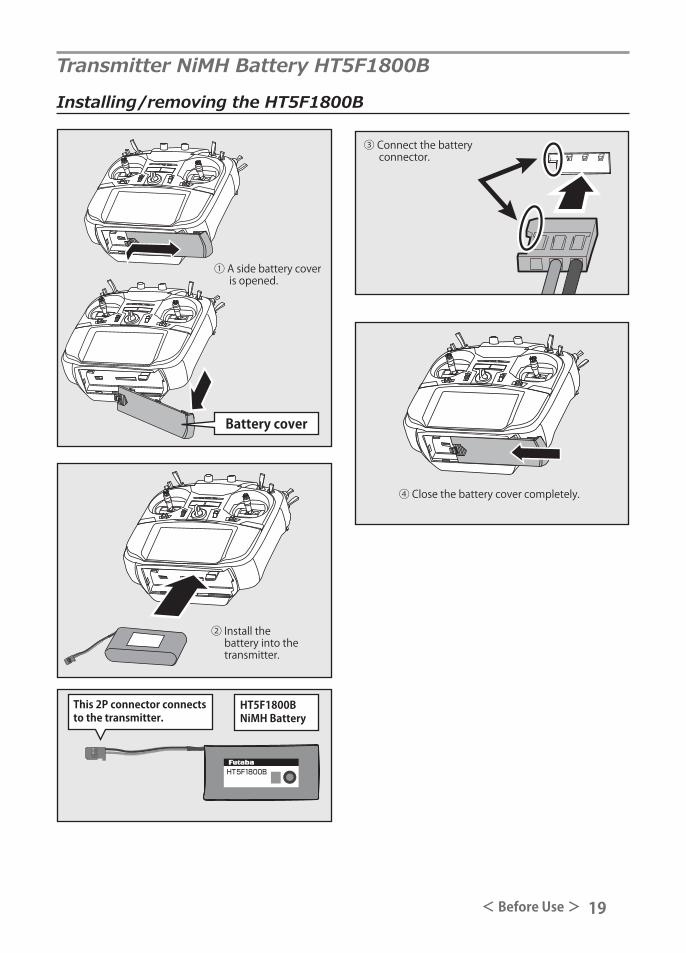
This 2P connector connects to the transmitter.
Transmitter NiMH Battery HT5F1800B
④ Close the battery cover completely.
Installing/removing the HT5F1800B
Battery cover
① A side battery cover is opened.
② Install the battery into the transmitter.
HT5F1800BNiMH Battery
③ Connect the battery connector.

20 < Before Use >
Battery removalNote: If you remove the battery while the power is on, the data you have set will not be saved.1. Open the battery cover.2. Disconnect the battery connector.3. Close the battery cover completely.
1.Plug the transmitter cord of the special charger into the charging jack on the side of the transmitter.
2. Plug the charger into an AC outlet. 3. Check that the charging LED lights.
WARNING Be careful not to drop the battery.
Never disconnect the battery connector f r o m t h e T 1 6 S Z t r a n s m i t t e r a f t e r turning off the power until the screen is completely blank and the transmitter has shut down completely.
* Internal devices such as memories may be damaged.
* If there is any problem, the message "Backup Error" will be shown the next time when you turn on the power of the transmitter. Do not use the transmitter as it is. Send it to the Futaba service center.
WARNINGNever plug the charger into an outlet other than the indicated voltage.
*Plugging the charger into the wrong outlet could result in an explosion or fire.
Do not plug and unplug the charger when your hands are wet.
*It may cause an electric shock.
Do not overcharge/overdischarge the battery.
*Overcharging/Overdischarging a battery can result in burns, fire, injuries, or loss of sight due to over-heating, breakage, or electrolyte leakage.
CAUTION
When the charger is not in use, disconnect it from the AC outlet.
* Do this to prevent accidents and to avoid over-heating.
*Battery charging will not automatically stop. Re-move the battery and transmitter from the charger and remove the charger from the wall socket.
*It is recommended to reactivate the battery by cy-cling several times if the battery has not been used for a long period.
*In the case of NiMH batteries, you may find poor performance of the battery if you have used the bat-tery only for a short period or if you repeat charging while the battery is not fully discharged. It is sug-gested to discharge the battery to the recommended level after use. It is also recommended to charge the battery just before use.
The charging time when charging the HT5F1800B battery with the special charger is approximately 15 hours.
4. Disconnect the charge plug.5. Disconnect the AC plug.
Charger
AC
To transmitter charging jack
Charging a battery
21< Before Use >
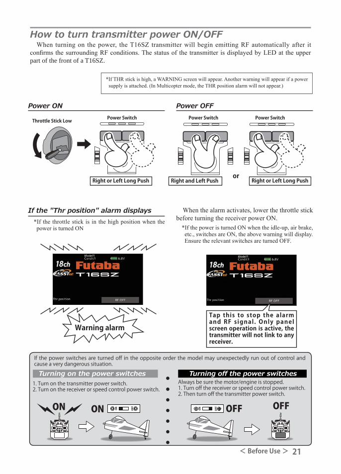
Power OFFPower ON
Throttle Stick Low Power Switch Power Switch Power Switch
Right and Left Push Right or Left Long PushRight or Left Long Pushor
1. Turn on the transmitter power switch.2. Turn on the receiver or speed control power switch.
Always be sure the motor/engine is stopped.1. Turn off the receiver or speed control power switch.2. Then turn off the transmitter power switch.
ON OFFOFFON
Turning on the power switches
If the power switches are turned off in the opposite order the model may unexpectedly run out of control and cause a very dangerous situation.
Turning off the power switches
How to turn transmitter power ON/OFF When turning on the power, the T16SZ transmitter will begin emitting RF automatically after it
confirms the surrounding RF conditions. The status of the transmitter is displayed by LED at the upper part of the front of a T16SZ.
*If THR stick is high, a WARNING screen will appear. Another warning will appear if a power supply is attached. (In Multicopter mode, the THR position alarm will not appear.)
If the "Thr position" alarm displays*If the throttle stick is in the high position when the power is turned ON
Warning alarmTap this to stop the alarm and RF signal. Only panel screen operation is active, the transmitter will not link to any receiver.
When the alarm activates, lower the throttle stick before turning the receiver power ON.
*If the power is turned ON when the idle-up, air brake, etc., switches are ON, the above warning will display. Ensure the relevant switches are turned OFF.

22 < Before Use >
Touch Panel
HOME/EXIT and U.MENU/MON.
HOME/EXIT Button
U.MENU/MON. Button
Tap the panel with your finger to enter data.
*Plastic film is attached to the Touch Panel. Please be careful so that you don't scratch the Touch Panel with anything hard such as a metal object. Don't push the Touch Panel with excessive force or drop anything on the panel.
*Although you may find some air bubbles under the plastic panel due to environmental changes such as temperature, it is not a defect and will cause no problems.
*Color LED is made from many pixels. Some pixels hold lighting. Moreover, some pixels go out. And a screen may flicker. Such condition is the characteristics of color LED. It is not failure.
Press To user menu display
Press and hold To servo monitor display
HOME/EXIT
U.MENU/MON.
Press Return to the previous screen
Press and hold Return to the home screenPress from HOME
screen. To Telemetry display
Press and hold from HOME screen. Panel lock / Lock release
Tapping the settings buttons for each value on the settings screen will cause value input buttons to appear at the top of the panel.
Value input buttons display at the top of the panel.
Pressing and holding a value will return it to its default setting.
Small change in value
Large change in value
Large change in value

23< Before Use >
Panel lockTemporarily activating this function makes it impossible to change data by mistakenly touching keys
during flight.
RF off modeModel operation is not possible, but panel operation without RF signal transmission is allowed.
(Reduces battery power consumption during set-up.)
Panel lock
Panel unlock
HOME/EXIT Press and hold
Restart the power to transmit RF signals."RF off" Model
operation is not possible, but only panel operation is.
U.MENU/MON.Press and Power ON
Lock Display
How to lock
How to unlock
1. The home screen is displayed.2. Press the HOME/EXIT button for about 1
second. "Key mark" is displayed and the keys disabled.
1. Press the Home/Exit button for about 1 second, and the panel will then become unlocked.
HOME/EXIT Press and hold
CAUTIONThe T16SZ's touch screen is very sensitive. To
avoid accidentally activating it during a flight, it is suggested that it be locked. Due to the touch screen's sensitivity, allowing it to be touched during flight by a neck strap hook, servo extension, or even your hand could be dangerous. Please use the Touch Panel lock for added safety during flight.

24 < Before Use >
FASSTest mode → Light Blue lightFASST mode → Green lightFHSS mode → Yellow-green lightRF-OFF → Violet lightStarting → Red lightTrainer Student → Blue lightRange check mode → Slow blinkingReceiver link mode → Fast blinking
Monitor LED displayThe status of the transmitter is displayed by LED at the upper part of the front of a T16SZ.
Stick control
Yaw axis
Pitch axis
Elevator Stick
Aileron stick
Throttle stick
Engine/motor Power
Rudder stick
Roll axis
*Example Stick Mode2

25< Before Use >
Stick control : Airplane ExampleA general model example. (There is also a different operational model.)
Right roll
Left roll
Straight
A rudder is right.
A rudder is left.
The left aileron is down.
The left aileron is up.
Level flightLevel flight
The right aileron is up.
The right aileron is down.
Elevator is up.
Elevator is down.
Aileron stick
To the right
Neutral Neutral
Nose Up
Nose Down
Middle
High throttle
Low throttle
Roll Axis Control
Yaw Axis Control Throttle Control
Elevator stick
UP(moved to the bottom)
Elevator stick
DOWN(moved to the top)
Aileron stick
To the left
Pitch Axis Control
Rudder stick
To the right
Neutral
Rudder stick
To the left
Nose Right
Nose Left
Throttle stick
MIDDLE(neutral)
Throttle stick
HIGHT(moved to the top)
Throttle stick
SLOW(moved to the bottom)
*Example Stick Mode2

26 < Before Use >
Stick control : Helicopter ExampleA general model example. (There is also a different operational model.)
Right roll
Left roll
Straight
Hovering
Rise
Descent
Level flight
Level flight
Aileron stick
To the right
Neutral Neutral
Nose Up
Nose Down
Middle
HighPitch Up
Pitch Down
Slow
Roll Axis Control
Yaw Axis Control Throttle /Pitch Control
Elevator stick
UP(moved to the bottom)
Elevator stick
DOWN(moved to the top)
Aileron stick
To the left
Pitch Axis Control
Rudder stick
To the right
Neutral
Rudder stick
To the left
Nose Right
Nose Left
Throttle stick
MIDDLE(neutral)
Throttle stick
HIGHT(moved to the top)
Throttle stick
SLOW(moved to the bottom)
*Example Stick Mode2

27< Before Use >
Stick control : Multicopter ExampleA general model example. (There is also a different operational model.)
Stop
Right roll
Right slide
Back slide
Front slideLeft slide
Left roll
Hovering
Rise
Descent
HoveringLevel flight Hovering
Level flight
HoveringLevel flight
Aileron stick
To the right
Neutral Neutral
Nose Up
Nose Down
Roll Axis Control
Yaw Axis Control Throttle Control
Elevator stick
UP(moved to the bottom)
Elevator stick
DOWN(moved to the top)
Aileron stick
To the left
Pitch Axis Control
Rudder stick
To the right
Neutral
Rudder stick
To the left
Nose Right
Nose Left
Throttle stick
MIDDLE(neutral)
Throttle stick
HIGH(moved to the top)
Throttle stick
SLOW(moved to the bottom)
*Example Stick Mode2

28 < Before Use >
Stick Adjustment
Lever head Lever headA B
Adjustment of the stick lever length
You can adjust the length of stick levers as you like. It is recommended to adjust the length of the sticks in line with your hand size.
1. Hold the lever head "B" and turn the lever head "A" counter-clockwise. The lock will be released.
2. Turn the lever-head "A" clockwise as you hold the lever-head "B" after placing it as you like.
Adjustment of stick lever tension
The tension of the self-return type stick lever can be adjusted.1. First, remove the battery cover on the
bottom of the transmitter. Next, unplug the battery wire and remove the battery from the transmitter.
2. Next, using a hand, remove the transmitter's side cover (rubber). When using Mode 2, you will need to remove the side cover to expose the tension screw.
Side cover
Rear Grip
It removes from here
*It is difficult to remove rear grips from the central site of a transmitter. Therefore, remove from the outside of rear grips.
Rear Grip
4. Use a 1.5mm hexagonal wrench to adjust the spring strength as you prefer by turning the adjusting screw of the stick you want to adjust.*Turning the screw clockwise increases the tension.
CAUTION: If you loosen the screw too much, it can interfere with the operation of the sticks internally.
You can adjust how quickly the stick returns to neutral.
3. Using your hand remove the transmitter's rear rubber grips.

29< Before Use >
Turn screw clockwise.
Stick tension maximumStick tension minimum
Turn screw counter-clockwise.
1.5mm hexagonal wrench
•Stick Tension (J2)(Mode 2)
•Stick Tension (J1)(Mode 1/2)
•Stick Tension (J4)(Mode 1/2)
•Stick Tension (J3)(Mode 1)
5. At the end of adjustment, re-install the side cover and rear grips.
SD Card (secure digital memory card) (not included)The T16SZ transmitter model data can be stored by using any commonly found SD card. When
T16SZ transmitter update software is released, the software is updated using an SD card. The T16SZ is capable of using SD and SDHC cards (SD:32MB-2GB SDHC:4GB-32GB).
SD card reader/writerSaving model data and update files (released
from Futaba) into the SD card, you can use those files on your T16SZ transmitter. Equipment for reading and writing SD cards is available at most electronics stores.
Stored dataWhen you have a problem of saving or reading
data after a long period of use, please get a new SD card.
*We are not responsible for, and offer no compensation for, memory card data that fails or is damaged for any reason. Be sure to keep a backup of all important data stored in your SD card.

30 < Before Use >
CAUTIONBe sure to turn off the power to the t r a n s m i t t e r b e f o r e i n s e r t i n g o r removing the SD card.
As the SD card is a precision device, do not use excessive force when inserting.
SD card slot
②The SD card slot is shown here in the figure below.
*Pay attention to the proper orientation of the SD card, as shown here.
SD card slot
Battery cover
① The side battery cover is remove-able.
③ When the SD card is pressed in once again, the card will be released from the card slot and can be removed.
Inserting/removing the SD card
-When a SD card is installed in the T16SZ transmitter, a folder called "Futaba" is cre-ated. Folders called "LOG" and "MODEL" are created in this folder. The "MODEL" folder stores the model data and the "LOG" folder stores the telemetry log data.
-The telemetry log data recorded on the SD card can be converted to CSV format by the telemeter log converter released on our home page. When copying or moving a log file, always select both .FLI and .FLD file.

31< Before Use >
Connector for trainer functionWhen you use the trainer function, connect the
optional trainer cable between the transmitters for teacher and student.
*You can set the trainer function on the Trainer Function screen in the System menu.
Connector/Plug
WARNINGDo not connect any other chargers except the special charger to this charging connector.
Connector for battery chargerThis is the connector for charging the NiMH
battery HT5F1800B that is installed in the transmitter. Do not use any other chargers except the attached special charger corresponding to NiMH battery.
Rubber cover
TrainerConnector
S.BUS (S.I/F)Connector
ChargePlug
EarphonePlug
S.BUS connector (S.I/F)When using an S.BUS servo and telemetry
sensor, connect them both here.
Earphone plugConnecting a stereo headphone to this plug, the
speech information of telemetry can be heard.

32 < Before Use >
Link/Mode SwitchUse the small plastic screw driver that was
included with your receiver. The Link/Mode Switch is also used for the CH
mode selection.
Extra Voltage ConnectorUse this connector when using a voltage
telemetry device to send the battery voltage (DC0 ~ 70V) from the receiver to the transmitter.
You will need to purchase the optional External Voltage input cable (CA-RVIN-700) FUTM5551.
You can then make a cable with an extra connector to the External voltage connector.
Before using the receiver, be sure to read the precautions listed in the following pages.
Receiver R7008SB
Connector"1 through 6": outputs for the channels 1
through 6"7/B": outputs of 7 channels and power. "8/SB": outputs of 8 channels or S.BUS port.[S.BUS Servo S.BUS Gyro ]*When using 8/SB as S.BUS, you have to set
CH MODE of the following page to mode B or mode D.
"S.BUS2": outputs of S.BUS2 port.[S.BUS2 Servo S.BUS2 Gyro Telemetry Sensor ]
*When using 9 or more channels, use an S.BUS function or use a second R7008SB and link both to your transmitter.
Connector insertion Firmly insert the connector in the direction
shown in the figure. Insert the S.BUS2 by turning it 90 degrees.
+
-
Do not connect either a switch or battery in this manner.Do not connect either a switch or battery in this manner.
ReceiverDANGERDANGER
DANGERDon't attach a connector as shown in the preceding illustration.
*It will short-circuit if connected in this way. A short circuit across the battery terminals may cause abnormal heating, fire and burns.
WARNINGS.BUS2 connectors
Don't connect an S.BUS servo / gyro to S.BUS2 connector.
LED Monitor This monitor is used to check the CH mode of
the receiver.
Receiver nomenclature

33< Before Use >
R7008SB CH ModeThe R7008SB receiver is a very versatile
unit. It has 8 PWM outputs, S.BUS and S.BUS2 outputs. Additionally the PWM outputs can be changed from channels 1-8 to channels 9-16. If you only desire to use it as an 8 channel receiver (without S.BUS), it can be used without any setting changes.
The T16SZ has the ability to link to two R7008SB receivers. One of them outputting channels 1-8 and the other outputting channels 9-16 gives you 16 PWM channels. Instructions for this configuration and S.BUS operation follow.
[How to change the R7008SB Channel mode.]1. Press and hold down the Link/Mode button
on the R7008SB receiver.2. Turn the receiver on while holding down
the Link/Mode button. When the LED begins to blink green/red the button may be released.
3. The LED should now be blinking red in one of the patterns described by the chart below.
4. Each press of the Mode/Link button advances the receiver to the next mode.
5. When you reach the mode that you wish to operate in, press and hold the Mode/Link button for more than 2 seconds.
6. Once locked into the correct mode the LED will change to a solid color.
7. Please cycle the receiver(s) power off and back on again after changing the Channel Mode.
Receiver connector
Setting channelMode A1-8CH
Mode B1-7CH
Mode C9-16CH
Mode D9-15CH
1 1 1 9 92 2 2 10 103 3 3 11 114 4 4 12 125 5 5 13 136 6 6 14 14
7/B 7 7 15 158/SB 8 S.BUS 16 S.BUS
Red LED blink 1 time 2 times 3 times 4 times
R7008SB CH MODE TABLE
DANGERDon't touch wiring.
* There is a danger of receiving an electric shock.
Do not short-circuit the battery terminals.
* A short circuit across the battery terminals may cause abnormal heating, fire and burns.
Please double check your polarity ( + and - ) when hooking up your connectors.
* If + and - of wiring are mistaken, it will damage, ignite and explode.
Don't connect to Extra Voltage before turning on a receiver power supply.
Default

34 < Before Use >
Receiver's Antenna InstallationThe R7008SB has two antennas. In order to maximize signal reception and promote safe modeling
Futaba has adopted a diversity antenna system. This allows the receiver to obtain RF signals on both antennas and fly problem-free.
To obtain the best results of the diversity func t ion , p lease re fe r to the fo l lowing instructions: 1. The two antennas must be kept as straight
as possible. Otherwise it will reduce the effective range.
2. The two antennas should be placed at 90 degrees to each other.
This is not a critical figure, but the most important thing is to keep the antennas away from each other as much as possible.
Larger models can have large metal objects that can weaken the RF signal. In this case the antennas should be placed at both sides of the model. Then the best RF signal condition is obtained at any flying attitude.
3. The antennas must be kept away from conductive materials, such as metal, carbon and fuel tank by at least a half inch. The coaxial part of the antennas does not need to follow these guidelines, but do not bend it in a tight radius.
4. Keep the antennas away from the motor, ESC, and other noise sources as much as possible.
*The two antennas should be placed at 90 degrees to each other. *The illustration demonstrates how the antenna should be placed. *Receiver Vibration and Waterproofing: The receiver contains precision electronic parts. Be sure to avoid vibration,
shock, and temperature extremes. For protection, wrap the receiver in foam rubber or other vibration-absorbing materials. It is also a good idea to waterproof the receiver by placing it in a plastic bag and securing the open end of the bag with a rubber band before wrapping it with foam rubber. If you accidentally get moisture or fuel inside the receiver, you may experience intermittent operation or a crash. If in doubt, return the receiver to our service center for service.
Antenna Antenna
Antenna
*Must be kept as straight as possible.
Coaxial cableR7008SB Receiver

35< Before Use >
Rubber grommet Brass eyelet
Wood screw
Servo mount
2.3-2.6mm nut washer Rubber grommet Brass eyelet
Servo mount
2.3-2.6mm screw
(Helicopter) (Airplane/Glider)
Servo lead wires To prevent the servo lead cable from being
broken by vibration during flight, provide a little slack in the cable and fasten it at suitable points. Periodically check the cable during daily maintenance.
Fasten about 5-10cm from the servo outlet so that the lead wire is neat secure.
Margin in the lead wire.
Mounting the power switch When mounting a power switch to an
airframe, make a rectangular hole that is a little larger than the total stroke of the switch so that you can turn the switch ON/OFF without binding.
Avoid mounting the switch where it can be covered by engine oil and dust. In general, it is recommended to mount the power switch on the side of the fuselage that is opposite the muffler.
Safety precautions when you install receiver and servos.
WARNINGConnecting connectors
Be sure to insert the connector until it stops at the deepest point.
How to protect the receiver from vibration and water
Wrap the receiver with something soft such as foam rubber to avoid vibration. If there is a chance of getting wet, put the receiver in a waterproof bag or balloon.
Receiver's antennaNever cut the receiver's antenna. Do not bind the receiver's antenna with the cables for servos.Locate the receiver's antenna as far as possible from metals or carbon fiber components such as frames, cables, etc.
*Cutting or binding the receiver's antenna will reduce the radio reception sensitivity and range, and may cause a crash.
Servo throwAdjust your system so that pushrods will not bind or sag when operating the servos to the full extent.
*If excessive force is continuously applied to a ser-vo, the servo could be damaged due to force on the gear train and/or power consumption causing rapid battery drain.
Mounting servosUse a vibration-proof rubber (such as rubber grommet) under a servo when mounting the servo on a servo mount. And be sure that the servo cases do not touch directly to the metal parts such as servo mount.
*If the servo case contacts the airframe directly, vibration will travel to and possibly damage the servo.
Mounting the Servo
Switch
Less than 5 mm of mounting plate
Attached screw
Switch cover

36 < Before Use >
S.BUS/S.BUS2 InstallationThis set uses the S.BUS/S.BUS2 system. The wiring is as simplified and clean mounting as possible,
even with models that use a large number of servos. In addition, the wings can be quickly installed to the fuselage without any erroneous wiring by the use of only one simple wire, even when there are a large number of servos used.●When using S.BUS/S.BUS2, special settings and mixes in your transmitter may be unnecessary. ●The S.BUS/S.BUS2 servos memorize the number of channels themselves. (settable with the T16SZ)●The S.BUS/S.BUS2 system and conventional system (receiver conventional CH used) can be mixed.
Receiver: R7008SB
Battery: FR2F1800 ( Optional )
Switch
Throttle servo: BLS173SV ( Optional )
Aileron servo: BLS174SV×2 ( Optional )
Elevator servo: BLS173SV×2 ( Optional )
Rudder Servo: BLS175SV×1 ( Optional )
HUB×3 ( Optional )
Receiver: R7008SB
Servo: S3174SV×9 ( Optional )
HUB×4 ( Optional )
S.BUS Glider usage example
S.BUS Aerobatic plane usage example

37< Before Use >
S.BUS Wiring example
WARNINGPower supply
Please make sure that you use a battery that can deliver enough capacity for the number and kind of servos used. Alkaline batteries cannot be used.
CH6Pitch
CH4Rudder
CH3Throttle
CH2Elevator
CH1Aileron
S.BUS Gyro CGY750 Connection example
CGY750Gyro
Battery
Battery
Switch
Switch
Receiver
Receiver
S.BUSPort(8/SB)
S.BUS Port(8/SB)
*When using 8/SB as S.BUS, you must set the receiver to Mode B or Mode D. See R7008SB CH MODE TABLE.
*When using 8/SB as S.BUS, you must set the receiver to Mode B or Mode D. See R7008SB CH MODE TABLE.
Battery
S.BUSExtension Cable
Terminal box
Hub Hub
Hub(Another power supply)
S.BUS ServoS.BUS Servo
●S.BUS Servo Since the channel number is memorized by the S.BUS itself, any connector can be used. When the SBD-1, SBD-2 (sold separately) is used, ordinary servos can be used with the S.BUS system.*SBD-1 cannot be used by S.BUS2 port.
●When separate power supply used When a large number of servos are used or when high current servos are used, the servos can be driven by a separate power supply by using a separate Power Supply 3-way hub.
●6-Terminal box (TB16PP)Six connectors can be inserted
●Hub(Another power supply)Used when using a separate power supply battery.
Switch
●HubThree connectors can be inserted.
Orange
Green
Optional Parts

38 < Before Use >
S.BUS2 System When using the S.BUS2 port, an impressive array of telemetry sensors may be utilized.
Receiver port S.BUS ServoS.BUS Gyro
S.BUS2 ServoS.BUS2 Gyro Telemetry sensor
S.BUS ○ ○ ×
S.BUS2 × (※) ○ ○
S.BUS2 TABLE
(※)Don't connect S.BUS Servo, S.BUS Gyro to S.BUS2 connector.
S.BUS2Port
S.BUSPort(8/SB)
Hub
Hub Hub Hub
Rudder Servo
S.BUS2 ServoS.BUS ServoS.BUS2 servo
Connection is possible
S.BUS2 gyroConnection is possible
S.BUS servoConnection is impossible
Telemetry sensorConnection is impossible
S.BUS2GYRO
CH Mode is set to ModeB [D].
+
Telemetry Sensor
S.BUS servos and gyros and S.BUS2 servos and gyros must be used in the correct receiver ports. Please refer to the instruction manual to make sure you connect to the correct one.

39< Before Use >
S.BUS/S.BUS2 device settingS.BUS/S.BUS2 servos or a telemetry sensor can be connected directly to the T16SZ. Channel setting and
other data can be entered for the S.BUS/S.BUS2 servos or sensors.
(S.BUS/S.BUS2 servo)
S.BUS/S.BUS2 device
3-Way hubor Y-harnesses
ReceiversBattery
(Telemetry sensor)
T16SZ
1. Connect the S.BUS device and battery youwant to set with a 3-way hub or Y-harnessesas shown in the figure.
2. Turn on the transmitter power.3. Call the setup screen. Servo: System Menu → S.BUS servo Sensor: Linkage Menu → Sensor4. Perform setting in accordance with each
screen.5. This sets the channel and other data for each
S.BUS servo, or telemetry device to be used with the S.BUS device or receiver.
*When connecting many current-consuming servos, please use an additional power supply hub.
And electric power is supplied to a servo with another power supply.
WARNINGDo not disconnect or turn transmitter power OFF while S.BUS servo and telemetry sensor data is being saved.■ S.BUS servo and sensor save data will be lost,
resulting in malfunction.

40 < Basic Operation >
System mode• System(FASSTest18CH etc.)
mode is displayed here.
Battery voltage for receivers• In FASSTest/T-FHSS mode, it is
displayed. Receiver voltage and Ext voltage display
The reception of the signal from the receiver to the transmitter is shown.
• This does not affect flight.
Timer1, Timer2• Timer is displayed here. Tap the time button to start/stop the
timer. (When the screen is tapped for 1 second, timer is reset to the initial value.)
Home screen
Digital trim (T1 to T4)• Trim position is displayed
here.
Model Name• The model name that
is currently used is displayed here.
RF Indicator
Date and Time
User's name
System timer• This shows the accumulated time
since the latest reset. (Each model / Total)(Hour):(Minute):(Second)
This is the Home screen and descriptions of its menus. Use your finger to operate the touch screen.
→ (Menu)• Model Tap the button to call Model
Menu screen.
→ (Menu)• System• Linkage• Model select Tap the button to call each Menu
screen.
Battery Indicator• When the battery voltage
reaches 5.8V, the alarm will beep. Land your a i rc raf t immediately.
Condition name• The condition name
that is currently used is displayed here.
WARNINGBe sure to confirm the model name before flying your aircraft.
Check the battery voltage as often as possible and try to charge the battery earlier. If the battery alarm makes a sound, land your aircraft immediately.
*You can adjust the LCD contrast by the display setting in the system menu.
BASIC OPERATION

41< Basic Operation >
Link procedure (T16SZ/R7008SB)Each transmitter has an individually assigned, unique ID code. In order to start operation, the receiver
must be linked with the ID code of the transmitter to which it is being paired. Once the link is made, the ID code is stored in the receiver and no further linking is necessary unless the receiver is to be used with another transmitter. When you purchase additional R7008SB receivers, this procedure is necessary; otherwise the receiver will not work. Link procedure1. Place the transmitter and the receiver close
to each other within half (0.5m) meter.
2. Turn on the transmitter. 3. Select [System type] at the Linkage menu
and access the setup screen shown below by tapping the screen.
4. When you use two receivers on one model, you must change from [Single] to [Dual].
*Only two receivers can be used. In "Dual", two setting items come out. Input, respectively.
5. Battery fail-safe voltage can be changed from the initial value of 3.8V here.
* Only in FASSTest/T-FHSS Mode.
6.[Link] is tapped. The transmitter will emit a chime as it starts the linking process.
7. When the transmitter starts to chime, power on the receiver. The receiver should link to the transmitter within about 1 second.
8. If linking fails, an error message is displayed. Bring the transmitter closer to the receiver and repeat the procedure above from Step 2.
Less than 0.5 m
In "Link" Mode
Receiver ONIn Dual, a primary receiver (Rx1) is linked first. Next, a secondary (Rx2) receiver is linked.
ID of a primary receiver displays.
ID of a secondary receiver displays.