instruction manual cygnus - · pdf filerefer to the cygnus instruction manual for additional...
TRANSCRIPT

222 W. Memorial Road, Oklahoma City, OK 73114 Phone: 1-800-624-7697 Fax: 405-755-8425 www.magpowr.com E-mail: [email protected]
INSTRUCTION MANUAL
CYGNUS® DIGITAL TENSION READOUT AND CONTROL
CYGNUS-E
CYGNUS-DIN All of the information herein is the exclusive proprietary property of Maxcess International, and is disclosed with the understanding that it will be retained in confidence and will neither be duplicated nor copied in whole or in part nor be used for any purpose other than for which disclosed. Copyright 2004, all rights reserved. Periodically there will be updates to this manual. The latest version is available at www.magpowr.com or by calling 1-800-MAGPOWR (624-7697). 850A295-1 03/09 Rev. F

2
CYGNUS BASIC SET-UP
This page provides a summary of the basic set-up and calibration of the CYGNUS control. Additional features and options of the CYGNUS control are described later in this manual. 1. The connections that are required for the basic CYNGUS system are the following: (see
sections 2.0 and 3.0 for specific wiring requirements.) • 115 or 230 VAC power (TB2.1 and TB2.2) • One or two load cells (TB6.1 through TB6.4, see section 6.3) • RUN/STOP using the CYGNUS internal logic supply between TB3.1 and TB3.2 (this
is typically accomplished by using a switch between these terminals) • E-STOP jumper between TB3.2 and TB3.3. • Analog control output to clutch or brake amplifier, current-to-pressure transducer,
motor controller, etc. (TB1.1 through TB1.4, refer to section 6.2.2 for output configuration)
2. When using a power amplifier, set the current range jumper to the proper setting for the
clutch or brake being used (refer to amplifier User’s Manual and the clutch or brake User’s Manual for proper settings). The following is also required:
• Power amplifier input (if used), 115 vac for PS-90 or 24 vac or vdc for PS-24 • Output from power amplifier to clutch or brake.
3. Close the RUN/STOP circuit (TB3.1 and TB3.2) to put the CYGNUS into HOLD mode (see section 6.1.1).
4. Calibrate the load cells (refer to section 6.3).
• During load cell calibration, be sure to select the appropriate system type (section 6.3 lists the system type options available).
5. Turn tension on by pressing the TENSION ON/OFF key and put the CYNGUS into AUTO
mode by switching open the RUN/STOP circuit. Run the machine at a reduced line speed and observe the system.
6. Refer to Section 7.0 for tuning methods that will optimize the responsiveness (Auto Tune is
recommended) and proceed to dynamically tune the system. 7. Basic set-up is complete. Refer to the CYGNUS instruction manual for additional features
and options. Always use the RUN/STOP feature to put the CYGNUS into HOLD mode whenever the machine is stopped to avoid a possible high-tension condition during start-up.

3
TABLE OF CONTENTS Section Description Page 1.0 Introduction ...................................................................................................................4 2.0 Installation.....................................................................................................................4 3.0 Electrical Connections ..................................................................................................5 4.0 Installation of Model PS-90 and PS-24 Power Amplifiers.............................................5 5.0 Keypad Navigation........................................................................................................6 6.0 System Set-Up..............................................................................................................7 6.1 Hardware Configuration................................................................................................7 6.1.1 Run/Stop .......................................................................................................................7 6.1.2 E-Stop ...........................................................................................................................7 6.2 Software Configuration .................................................................................................8 6.2.1 Change Display Settings (optional) ..............................................................................8 6.2.2 I/O configuration............................................................................................................9 6.2.3 Remote Tension Set Point/Set-up Select (optional) ...................................................10 6.3 Load Cell Calibration (required)..................................................................................11 6.3.1 Precision Calibration...................................................................................................11 6.3.2 Weightless Calibration ................................................................................................12 6.4 Optional Input Device Calibration ...............................................................................13 6.4.1 Web Velocity Calibration ............................................................................................13 6.4.2 RPM Calibration..........................................................................................................14 6.4.3 Diameter Calibration ..................................................................................................15 6.5 Output Calibration (optional).......................................................................................16 7.0 Tuning (required) ........................................................................................................17 7.1 Quick Stabilize ............................................................................................................17 7.2 Optimize Manual Tuning.............................................................................................18 7.3 Auto Tuning.................................................................................................................19 7.4 Direct Parameter Access Tuning (optional) ................................................................20 8.0 Optional Functions ......................................................................................................21 8.1 Changing Units of Measure or Language...................................................................21 8.2 Taper Tension (optional).............................................................................................22 8.3 Inertia / Acceleration Compensation (optional)...........................................................23 8.4 Hold Level Control (optional) ......................................................................................24 8.5 Gain Scheduling (optional) .........................................................................................25 8.6 Out of Round Roll (optional) .......................................................................................26 8.7 Alarms (optional).........................................................................................................27 8.8 Splice Features (optional) ...........................................................................................28 8.9 Inverse Diameter Output and Rewind Overspeed Output (optional)..........................29 8.10 Communication (optional) ...........................................................................................30 8.11 Set-ups........................................................................................................................31 8.11.1 Changing From One Set-Up to Another .....................................................................31 8.11.2 Copy Set-Ups..............................................................................................................31 8.12 Security Lock Out........................................................................................................32 9.0 Troubleshooting ..........................................................................................................33 9.1 Troubleshooting Out-of-Round Roll Compensation....................................................35 9.2 Out of Round Roll Comp Active..................................................................................35 9.3 Auto Tune Diagnostics................................................................................................36 9.4 Load Cell Diagnostics .................................................................................................37 9.5 Gain Scheduling Diagnostics......................................................................................39 9.6 Gain Scheduling Theory .............................................................................................39 9.7 Auto Tune and Gain Scheduling.................................................................................40 10.0 Alphabetical List of Screen Definitions .......................................................................40 Table 1 Load Cell Diagnostics .................................................................................................38 Table 2 Voltage Table for Remote Set-up Select ....................................................................57 Figure 1 System Types .............................................................................................................52 Figure 2 Field Bus Card Installation .........................................................................................53 Figure 3 Cygnus Wiring Diagram..............................................................................................54 Figure 4 Load Cell Wiring..........................................................................................................55 Figure 5 Digital Inputs Wiring Diagram .....................................................................................56 Figure 6 Wiring Diagram for Use of Remote Setup Select .......................................................57 Figure 7 Wiring Diagram for Remote Tension Setpoint ............................................................57 Figure 8 Cygnus-E Wiring Layout .............................................................................................58 Figure 9 Cygnus-DIN & Cygnus-E Outline Dimensions............................................................59 Specifications .............................................................................................................................60

1. INTRODUCTION The MAGPOWR® Model CYGNUS® is a microprocessor based control designed for precise closed loop tension control of a moving web. The CYGNUS is capable of controlling web tension in unwind, rewind, or point-to-point applications in any web press. 2. INSTALLATION INSTALLATION Model CYGNUS-E is intended for mounting on any flat vertical surface capable of supporting it. See Figure 9 for dimensions. The CYGNUS-E meets the environmental and mechanical requirements of EN50178. CYGNUS-E exceeds the environmental degree of protection requirement with an IP65 rating. If the IP65 rating is required in the final installation, sealing type cable grips should be used for cable entry. Four mounting holes are provided for attachment of the CYGNUS-E to the mounting surface. The means of attachment should comply with the essential requirements of the appropriate standard(s) and is the responsibility of the installer. Model CYGNUS-DIN is intended for installation through a DIN panel opening in a customer panel or enclosure. The panel itself must provide sufficient strength to support the weight of the CYGNUS-DIN as well as insure the integrity of the environmental seal. The CYGNUS-DIN maintains a degree of protection of IP65 over its front panel. It also meets the environmental and mechanical requirements of EN50178. The CYGNUS-DIN mounting clips found on both sides of the enclosure behind the front panel will accommodate panel thickness of 0.06 inches (1.5 mm) to 0.25 in. (6.9 mm). Wiring to and from the enclosure must be done with double or reinforced insulation or protective screening which provides protective separation. All wiring outside either of the CYGNUS enclosures should comply with the essential requirements of the appropriate local standard(s) and is the responsibility of the installer. If using a magnetic particle clutch or brake, see Figure 8 to install the Model PS-90 or PS-24 Power Amplifiers inside the CYGNUS-E enclosure.
WARNING: DISCONNECT MAINS BEFORE OPENING ENCLOSURE
MAINTENANCE The only maintenance that may be required on CYGNUS is fuse replacement. Replacement of any fuse requires opening the enclosure, which circumvents the enclosure IP rating. To replace a fuse: On Model CYGNUS-DIN: On Model CYGNUS-E: 1. Disconnect the supply mains. 1. Disconnect the supply mains. 2. Remove the four screws on the rear of 2. Open the door of the CYGNUS-E by loosening the CYGNUS which retain the top cover. the two retaining screws. 3. Remove the cover. 3. Remove the four screws on the rear of the 4. Remove and replace the blown fuse. CYGNUS which retain the cover. 5. Re-install cover. 4. Remove the cover. 6. Reconnect supply mains 5. Remove and replace the blown fuse. 6. Re-install cover. 7. Close the door and re-tighten the two retaining screws. 8. Reconnect supply mains.
4
5
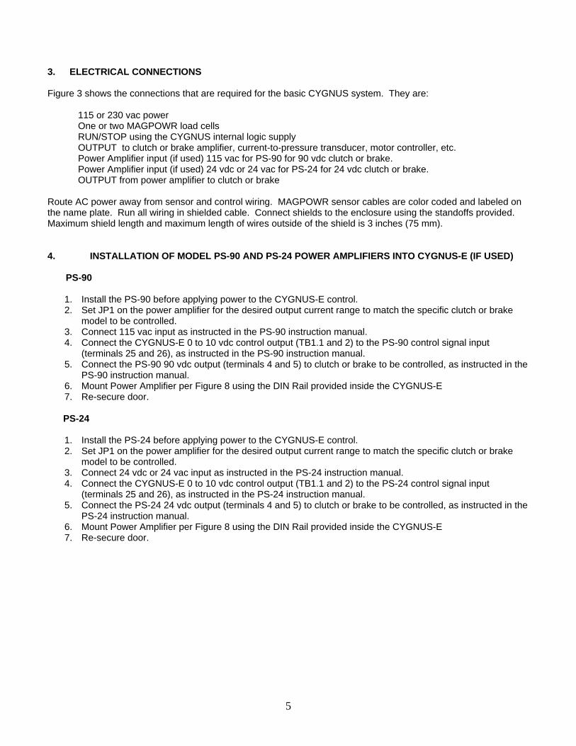
3. ELECTRICAL CONNECTIONS Figure 3 shows the connections that are required for the basic CYGNUS system. They are: 115 or 230 vac power One or two MAGPOWR load cells RUN/STOP using the CYGNUS internal logic supply OUTPUT to clutch or brake amplifier, current-to-pressure transducer, motor controller, etc. Power Amplifier input (if used) 115 vac for PS-90 for 90 vdc clutch or brake. Power Amplifier input (if used) 24 vdc or 24 vac for PS-24 for 24 vdc clutch or brake. OUTPUT from power amplifier to clutch or brake Route AC power away from sensor and control wiring. MAGPOWR sensor cables are color coded and labeled on the name plate. Run all wiring in shielded cable. Connect shields to the enclosure using the standoffs provided. Maximum shield length and maximum length of wires outside of the shield is 3 inches (75 mm). 4. INSTALLATION OF MODEL PS-90 AND PS-24 POWER AMPLIFIERS INTO CYGNUS-E (IF USED) PS-90
1. Install the PS-90 before applying power to the CYGNUS-E control. 2. Set JP1 on the power amplifier for the desired output current range to match the specific clutch or brake
model to be controlled. 3. Connect 115 vac input as instructed in the PS-90 instruction manual. 4. Connect the CYGNUS-E 0 to 10 vdc control output (TB1.1 and 2) to the PS-90 control signal input
(terminals 25 and 26), as instructed in the PS-90 instruction manual. 5. Connect the PS-90 90 vdc output (terminals 4 and 5) to clutch or brake to be controlled, as instructed in the
PS-90 instruction manual. 6. Mount Power Amplifier per Figure 8 using the DIN Rail provided inside the CYGNUS-E 7. Re-secure door.
PS-24
1. Install the PS-24 before applying power to the CYGNUS-E control. 2. Set JP1 on the power amplifier for the desired output current range to match the specific clutch or brake
model to be controlled. 3. Connect 24 vdc or 24 vac input as instructed in the PS-24 instruction manual. 4. Connect the CYGNUS-E 0 to 10 vdc control output (TB1.1 and 2) to the PS-24 control signal input
(terminals 25 and 26), as instructed in the PS-24 instruction manual. 5. Connect the PS-24 24 vdc output (terminals 4 and 5) to clutch or brake to be controlled, as instructed in the
PS-24 instruction manual. 6. Mount Power Amplifier per Figure 8 using the DIN Rail provided inside the CYGNUS-E 7. Re-secure door.

5.0 KEYPAD NAVIGATION Ten Tactile Feedback “smart” keys that change
Home Screen (Digital) functions as you navigate through different screens.
6
Function of each key corresponds to the displayed item next to it. Enter key is used to enter selected numeric data.
Back space key clears the last entry. Tension Setpoint Input Repeated pushing will take you back to (Press “Setpoint” key to reach this screen) Home Screen one step at a time. Numeric values are input using keys next to corresponding number Decimal point (Example shown would input a “1” in the Edit Setpoint screen) Home Screen (Analog) Hidden key feature allows operator to change from analog to digital display by depressing any of the top four keys when at the Home screen. Press again to return to digital home screen. General Navigation Home Key will always take you directly back to the “Home Screen”. Screen prompts that stretch across entire display can be accessed by pressing the button on either side.
7
6.0 SYSTEM SET-UP 6.1 HARDWARE CONFIGURATION
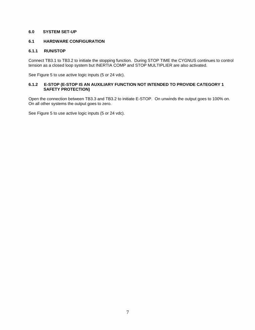
6.1.1 RUN/STOP Connect TB3.1 to TB3.2 to initiate the stopping function. During STOP TIME the CYGNUS continues to control tension as a closed loop system but INERTIA COMP and STOP MULTIPLIER are also activated. See Figure 5 to use active logic inputs (5 or 24 vdc). 6.1.2 E-STOP (E-STOP IS AN AUXILIARY FUNCTION NOT INTENDED TO PROVIDE CATEGORY 1
SAFETY PROTECTION) Open the connection between TB3.3 and TB3.2 to initiate E-STOP. On unwinds the output goes to 100% on. On all other systems the output goes to zero. See Figure 5 to use active logic inputs (5 or 24 vdc).

6.2 SOFTWARE CONFIGURATION
6.2.1 CHANGE DISPLAY SETTINGS (OPTIONAL)
(Home Screen) Adjusts numeric data update rate
8
Adjusts bar graph data update rate Adjusts screen contrast for different lighting conditions NOTE: Default values work well in most applications.

6.2.2 I/O CONFIGURATION
(Home Screen)
Select optional sensor type(s)
Select logic type
Toggle activates keypad, Level requires logic input
Logic can be active either high or low
Select desired input
The CYGNUS has two control outputs. One is isolated one is non-isolated. Check requirements to select appropriate output type.
See Section 6.2.3
Torque is the normal control output. For 1/Diameter and Velocity/Diameteoutputs see section 8.9
Select desired isolated control output(if using a power amplifier select 10 vdc)
9
r
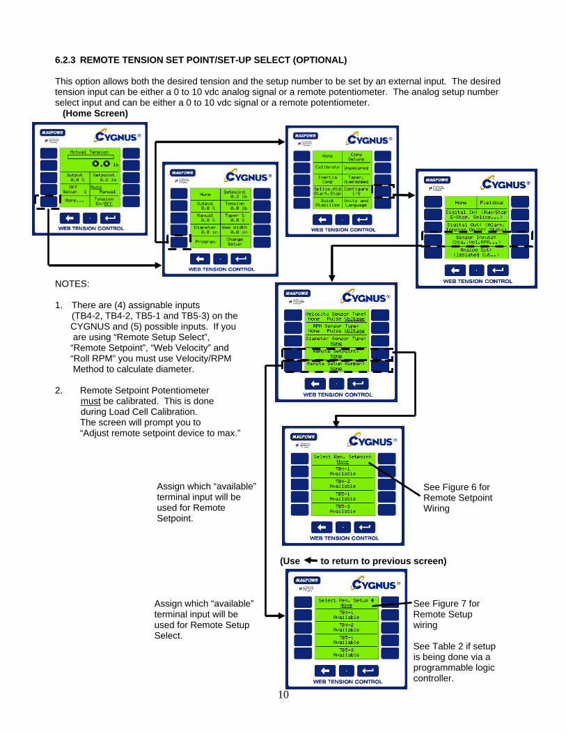
6.2.3 REMOTE TENSION SET POINT/SET-UP SELECT (OPTIONAL) This option allows both the desired tension and the setup number to be set by an external input. The desired tension input can be either a 0 to 10 vdc analog signal or a remote potentiometer. The analog setup number select input and can be either a 0 to 10 vdc signal or a remote potentiometer. (Home Screen) NOTES: 1. There are (4) assignable inputs
(TB4-2, TB4-2, TB5-1 and TB5-3) on the CYGNUS and (5) possible inputs. If you are using “Remote Setup Select”, “Remote Setpoint”, “Web Velocity” and “Roll RPM” you must use Velocity/RPM Method to calculate diameter. 2. Remote Setpoint Potentiometer must be calibrated. This is done during Load Cell Calibration. The screen will prompt you to “Adjust remote setpoint device to max.” Assign which “available” terminal input will be used for Remote Setpoint. (Use to return to previous screen)
10
Assign which “available” See Figure 7 for terminal input will be Remote Setup
See Figure 6 for Remote Setpoint Wiring
used for Remote Setup wiring Select. See Table 2 if setup is being done via a programmable logic controller.

6.3 LOAD CELL CALIBRATION (REQUIRED) 6.3.1 PRECISION CALIBRATION This is the most accurate method of calibration. Use for all applications in which tension accuracy is critical.
(Home Screen)
11
Confirm system type Refer to Figure 1 Enter maximum tension. This will scale the analog meter and bar graph. (Usually Confirm load it is best to set max. tension cell type approx. twice the value of (See Figure 4 the normal running tension.) for wiring load . cell) . Instruction to unload roll This is the calibration Confirm Value weight that will be Confirm Value used to calibrate the the load cells. Press Instruction to apply calibration weight “Precision Calibration” to continue. Next to complete calibration

6.3.2 WEIGHTLESS CALIBRATION This is a quick method of calibrating load cells without the need of hanging weights to simulate tension. For tension critical applications use the Precision Calibration method. (NOTE: Repeatability and sensor performance will not be affected) (Home Screen)
12
Confirm system type (See Figure 1) Enter combined load cell rating. (If two load cells are used, that is the sum of the rating.) Enter web wrap angle NOTE: Refer to load cell instruction manual or Designer’s Notebook for explanation of wrap angle. Confirm maximum tension Confirm wrap angle (typically twice setpoint) Confirm combined Confirm load cell type load cell rating (See Figure 4 for correct load cell wiring) Next to complete calibration
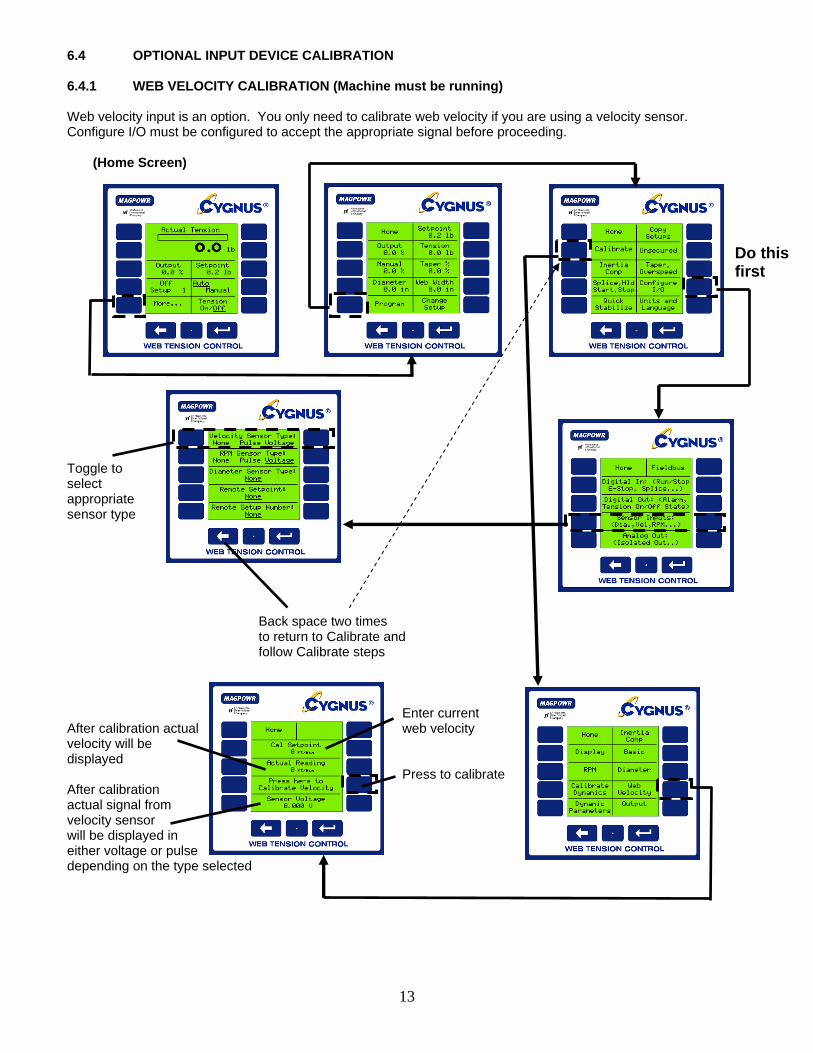
6.4 OPTIONAL INPUT DEVICE CALIBRATION 6.4.1 WEB VELOCITY CALIBRATION (Machine must be running) Web velocity input is an option. You only need to calibrate web velocity if you are using a velocity sensor. Configure I/O must be configured to accept the appropriate signal before proceeding. (Home Screen)
13
Toggle to select appropriate sensor type Back space two times to return to Calibrate and follow Calibrate steps Enter current After calibration actual web velocity velocity will be displayed Press to calibrate After calibration actual signal from velocity sensor will be displayed in either voltage or pulse depending on the type selected
Do thisfirst

6.4.2 RPM CALIBRATION (Machine must be running) If using an optional RPM sensor you must calibrate the output of the sensor so the CYGNUS can recognize actual RPM. (Home Screen)
14
Press “Home” after calibration is complete Enter current Rewind RPM Actual RPM will be displayed after calibrating Press to calibrate After calibration, actual signal from velocity sensor will be displayed in either voltage or pulse depending on the type selected.
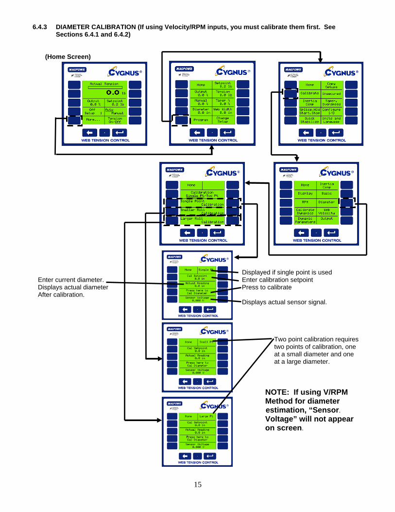
6.4.3 DIAMETER CALIBRATION (If using Velocity/RPM inputs, you must calibrate them first. See Sections 6.4.1 and 6.4.2)
(Home Screen)
15
Displayed if single point is used Enter current diameter. Enter calibration setpoint Displays actual diameter Press to calibrate After calibration. Displays actual sensor signal. Two point calibration requires two points of calibration, one at a small diameter and one at a large diameter. NOTE: If using V/RPM
Method for diameter estimation, “Sensor.
Voltage” will not appear on screen.

6.5 OUTPUT CALIBRATION (OPTIONAL) (Home Screen)
16
Select output to be calibrated and follow screen prompts.
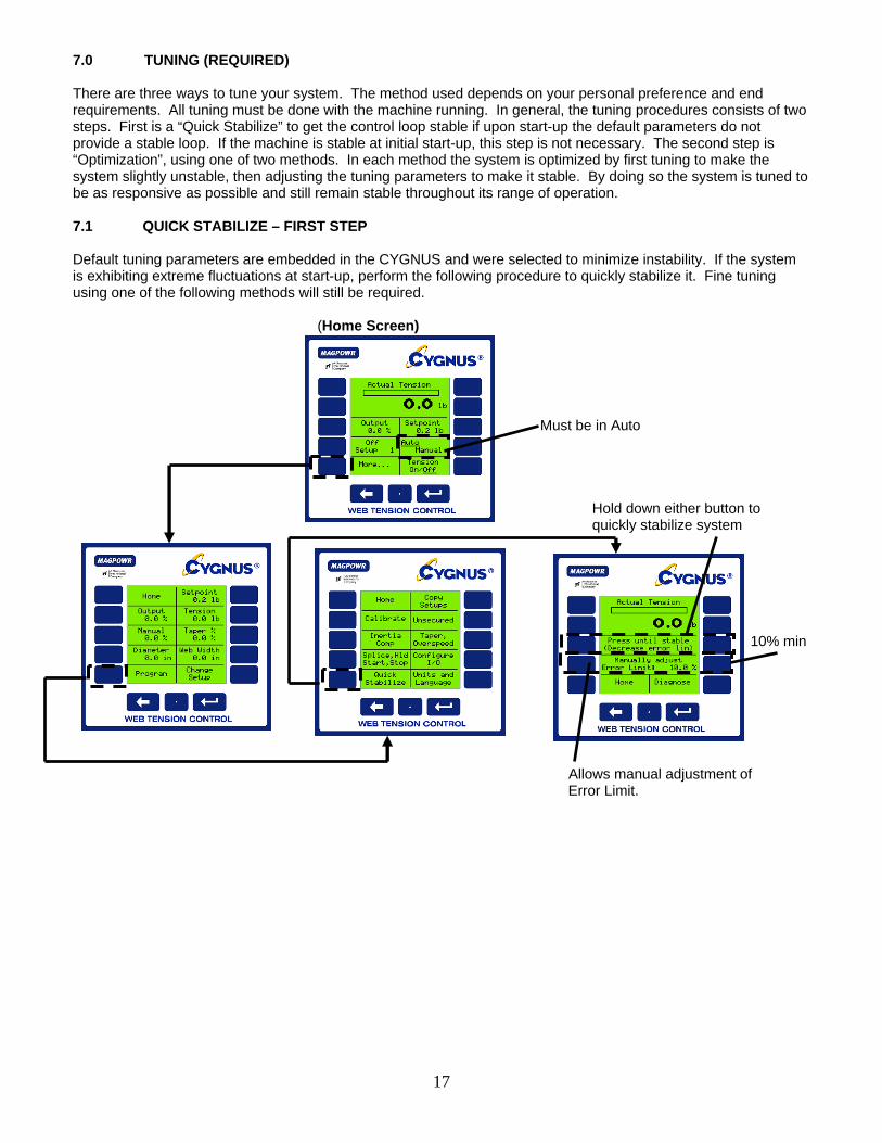
7.0 TUNING (REQUIRED) There are three ways to tune your system. The method used depends on your personal preference and end requirements. All tuning must be done with the machine running. In general, the tuning procedures consists of two steps. First is a “Quick Stabilize” to get the control loop stable if upon start-up the default parameters do not provide a stable loop. If the machine is stable at initial start-up, this step is not necessary. The second step is “Optimization”, using one of two methods. In each method the system is optimized by first tuning to make the system slightly unstable, then adjusting the tuning parameters to make it stable. By doing so the system is tuned to be as responsive as possible and still remain stable throughout its range of operation. 7.1 QUICK STABILIZE – FIRST STEP Default tuning parameters are embedded in the CYGNUS and were selected to minimize instability. If the system is exhibiting extreme fluctuations at start-up, perform the following procedure to quickly stabilize it. Fine tuning using one of the following methods will still be required. (Home Screen) Must be in Auto Hold down either button to quickly stabilize system 10% min Allows manual adjustment of Error Limit.
17
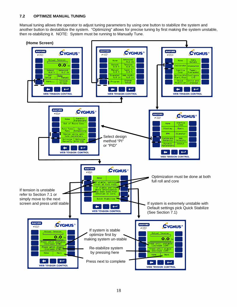
7.2 OPTIMIZE MANUAL TUNING Manual tuning allows the operator to adjust tuning parameters by using one button to stabilize the system and another button to destabilize the system. “Optimizing” allows for precise tuning by first making the system unstable, then re-stabilizing it. NOTE: System must be running to Manually Tune. (Home Screen)
18
Select design method “PI” or “PID” Optimization must be done at both full roll and core If tension is unstable refer to Section 7.1 or simply move to the next screen and press until stable If system is extremely unstable with Default settings pick Quick Stabilize (See Section 7.1) If system is stable optimize first by making system un-stable Re-stabilize system by pressing here Press next to complete

7.3 AUTO TUNING By pressing a single button, the CYGNUS has the unique ability to automatically determine the stable/optimized tuning parameters for most systems. NOTE: Systems with large transients may require manual tuning as outlined in Section 7.2. System must be running in Manual Mode to Auto Tune. (Home Screen)
19
You can choose different design methods without “Auto Tuning” again. (Example: if “PID” is too aggressive you can change to “PI”). Select design method NOTE: Will automatically return to previous screen. Press “start” to begin tuning. A pop-up screen will indicate Auto Tune success and you will automatically be taken to the design method screen. If Auto Tune is not successful, the “Disturbance Level” may be too low. Try Enter disturbance level. increasing it, and repeat the procedure. This is a forced disturbance that is a Enter manual output level before tuning. percentage of manual level used to tune the system.
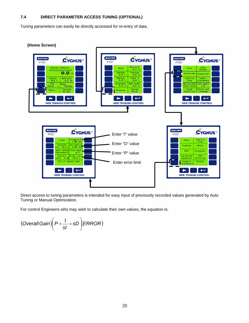
7.4 DIRECT PARAMETER ACCESS TUNING (OPTIONAL) Tuning parameters can easily be directly accessed for re-entry of data. (Home Screen)
20
Enter “I” value Enter “D” value Enter “P” value Enter error limit Direct access to tuning parameters is intended for easy input of previously recorded values generated by Auto Tuning or Manual Optimization. For control Engineers who may wish to calculate their own values, the equation is:
( ) ( )ERRORsDsI
PGainOverall ⎟⎟⎠
⎞⎜⎜⎝
⎛++
1

8.0 OPTIONAL FUNCTIONS 8.1 CHANGING UNITS OF MEASURE OR LANGUAGE (Home Screen)
21
Select language Select units NOTE: Conversion of existing units is automatically made. No re-calibration is required. Select units

8.2 TAPER TENSION (OPTIONAL) Taper Tension is the reduction of tension as the diameter increases on a rewind. Taper Tension is desired on rewinds to prevent crushed cores and telescoping rolls caused by excess tension build up. Taper can be achieved by either estimating diameter, using the optional diameter input, or calculating diameter based on roll RPM and Velocity inputs (see Section 6.4 to calibrate these devices) (Home Screen)
22
Select “YES” to enable taper Enter “%” taper required Enter Full Roll diameter Enter Core diameter NOTE: “% Taper” is dependent on material and machine type and is totally subjective. Determination of the correct amount of taper for your application is a trial and error process.

8.3 INERTIA / ACCELERATION COMPENSATION (OPTIONAL) This option is used for heavy rolls where the inertia negatively affects stopping and starting and acceleration/deceleration. With this feature the CYGNUS can compensate for the inertia and maintain better control. NOTE: This feature only works with linear ramping of velocity. While Inertia Comp can be used without Auxiliary Inputs, best results will be achieved when using a Diameter Input. Accel Comp requires a web velocity input, but may be used without a diameter input. For best results, use a DC diameter input. (Home Screen)
23
Requires Diameter and Velocity Calibration. Select when Accel Comp option is used Select when Inertia Comp option is used during stopping. Requires Diameter NOTE: Accel Comp can Calibration. be used for both acceleration and deceleration. Enter calibration roll weight Enter Core Inertia Enter calibration roll diameter Enter Core Diameter Enter calibration roll width Enter time it will take to decelerate from max. velocity Enter maximum velocity. Go to calibrate. Diameter Enter time it will take to Calibration must be done accelerate to max. velocity before “inertia Comp” is used. Enter the rate of acceleration/
deceleration required to activate the accel/decal feature
INERTIA COMP ACCEL/DECEL COMP
(Velocity sensor and calibration always required) Best DC Voltage Diameter Sensor DC Voltage Diameter Sensor
Better Calculated Diameter (RPM and Velocity inputs required. Calibration of
both required)
Calculated Diameter (RPM input also required. RPM calibration required)
Good Estimated Diameter Estimated Diameter

8.4 HOLD LEVEL CONTROL (OPTIONAL) Hold Level is used to keep tension in the web after a machine is run through a controlled stop and is at rest. This level is adjustable from 0 to 100% of maximum output and should be set just high enough to prevent roll rotation while stopped, but not higher than necessary, since this value may have a momentary effect on tension at start. Hold level can be configured as a fixed value, to change with output, to change with tension setpoint, to change with diameter, or to change with tension and diameter. (Home Screen)
24
Enter Hold Level as a percent of output Used only when “hold level changes with output” is selected. Set to 1.0 otherwise. (See below) Select Hold Level option Hold Level will go to output % When selected Hold Level selected when machine experiences will be the last running a controlled stop output multiplied by the Hold Multiplier Hold Level will be scaled to change with changes in tension set point NOTE: Requires Diameter Calibration NOTE: Requires diameter calibration. Hold Level will change as Hold Level will change with both diameter changes. tension and diameter. Any change in tension, diameter or Hold Level will rescale Hold Output. See Section 6.4 for calibration of diameter input devices.
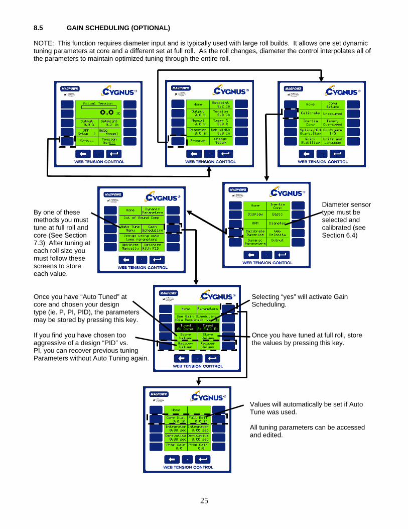
8.5 GAIN SCHEDULING (OPTIONAL) NOTE: This function requires diameter input and is typically used with large roll builds. It allows one set dynamic tuning parameters at core and a different set at full roll. As the roll changes, diameter the control interpolates all of the parameters to maintain optimized tuning through the entire roll.
25
Diameter sensor By one of these type must be methods you must selected and tune at full roll and calibrated (see core (See Section Section 6.4) 7.3) After tuning at each roll size you must follow these screens to store each value. Once you have “Auto Tuned” at Selecting “yes” will activate Gain core and chosen your design Scheduling. type (ie. P, PI, PID), the parameters may be stored by pressing this key. If you find you have chosen too Once you have tuned at full roll, store aggressive of a design “PID” vs. the values by pressing this key. PI, you can recover previous tuning Parameters without Auto Tuning again. Values will automatically be set if Auto Tune was used. All tuning parameters can be accessed and edited.

8.6 OUT OF ROUND ROLL COMPENSATION (OPTIONAL) CYGNUS has the unique ability to compensate for the Velocity/Tension transients caused by out of round rolls. This feature requires a roll RPM sensor input into TB4.2 and TB4.3. The RPM sensor must be a pulse type which outputs 1 pulse per revolution of the out-of-round roll. Calibrate RPM sensor per Section 6.4.2 of this manual. (NOTE: The system must be dynamically tuned before enabling this function.) If system is unstable reduce the gain. Select yes to enable out of round roll configuration. Actual RPM will be displayed here This is “NOT” maximum roll RPM. This once RPM is calibrated. value is set automatically after you “Auto Tune” the system, and is the
maximum RPM the out of round roll comp can tolerate. This is the cut-
off RPM to ensure you are not crossing the natural frequency of the system. If the system will not stabilize, set this value below the RPM at which oscillations start.
26

8.7 ALARMS (OPTIONAL) The Alarm Output is used to detect low or high tension and provide indication to an outside device. It is typically used for “Web Break Detection”. (Home Screen) Select Maximum output current Set whether Alarm is used of alarm signal. Typically 5 madc for 5 vdc logic and 100 madc for 24 vdc logic. Enter % of tension setpoint At which alarm actuates. Below 100% for low tension Above 100% for high tension. Set time delay before alarm activates. (Default is 0 seconds)
27

8.8 SPLICE FEATURES (OPTIONAL) The CYGNUS contains helpful splice tools that control output during a splice and can reduce the tension transients typically experienced during a splice.
28
Typically input the inverse of the build ratio.
dia.core
dia.rollfullMax.Use Unwind = For
rollfulldia.coreUse Rewind For =
Selecting “yes” will take If the new roll feature is used, each time the last running output and the tension is turned off this screen will multiply by the splice appear. multiplier value Select YES if you are starting a new roll The operator will be prompted to enter the new roll diameter

8.9 INVERSE DIAMETER OUTPUT AND REWIND OVERSPEED OUTPUT (OPTIONAL) The inverse diameter output and velocity divided by diameter output function is used to slow the motor/drive input RPM to a clutch as a rewind roll builds. This minimizes the slip watts required to be dissipated by the clutch and extends clutch life. This connection is labeled 1/D and is connected between TB4.3 and TB4.4 and is the non-isolated output. See section 6.2.2 to configure the non-isolated output for 1/Dia or Velocity/Diameter. A diameter sensor is always required and a velocity sensor is needed when using Velocity/Diameter, see section 6.2.2 to select the sensor types. See section 6.4.1 and 6.4.3 to calibrate velocity and diameter.
29
The output is the RPM to the clutch motor. The motor controller should be scaled to produce the RPM required at maximum velocity and core diameter plus the required overspeed percentage when the input to the motor controller is 10 volts. Enter Core Diameter and Not shown for 1/Dia Maximum Velocity.
1/Dia Output (in volts)
ActualDiameterCoreDiameterOutput
__*10=
Vel/Dia Output (in volts)
MaximumVelocityActualVelocity
ActualDiameterCoreDiameter
__*
__*10= Output

8.10 COMMUNICATION (OPTIONAL) The CYGNUS connects to an Ethernet, DeviceNet or Profibus-DP bus through an optional HMS fieldbus system gateway. The gateway formats the data for the specific field bus. See Figure 2 for HMS gateway card installation. See COMMKIT manual for function address locations.
30
Select “HMS” to activate communication Indicated communication status. This will also be displayed on the HOME screen: Bus protocol will be displayed here |?|=Indicates “HMS” has been selected, but gateway is CYGNUS will automatically not present. identify the gateway and bus protocol. |*|=Indicates gateway is present, but bus is not connected. |-|=Indicates bus communication has been established successfully. Refer to COMMKIT instruction manual for interface card setup instructions and a list of parameters.

8.11 SETUPS The CYGNUS stores up to (10) individual setups for machines that run multiple materials. Individual setups can include different tuning parameters, hold levels and tension set points. Each is independent of the other setup but can be copied if many parameters are similar. 8.11.1 CHANGING FROM ONE SET-UP TO ANOTHER Select setup (Home Screen) 8.11.2 COPY SETUPS A time saving shortcut when setting up two similar setups is to copy from one to another. Follow screen prompts to copy setups.
31
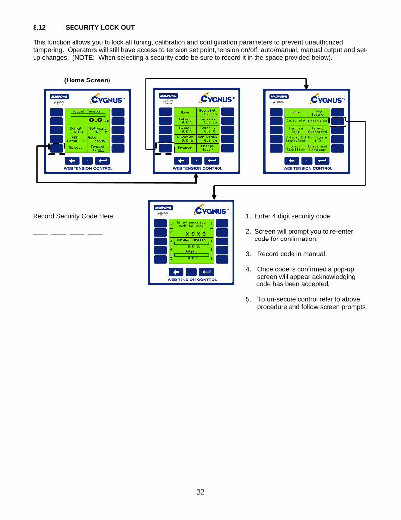
8.12 SECURITY LOCK OUT This function allows you to lock all tuning, calibration and configuration parameters to prevent unauthorized tampering. Operators will still have access to tension set point, tension on/off, auto/manual, manual output and set-up changes. (NOTE: When selecting a security code be sure to record it in the space provided below). (Home Screen) Record Security Code Here: 1. Enter 4 digit security code. ____ ____ ____ ____ 2. Screen will prompt you to re-enter code for confirmation.
3. Record code in manual. 4. Once code is confirmed a pop-up
screen will appear acknowledging code has been accepted.
5. To un-secure control refer to above procedure and follow screen prompts.
32

9.0 TROUBLESHOOTING
Problem Possible Cause Solution or Diagnostic
Activating Gain Scheduling caused instability, and deactivating did not cure.
Gain Scheduling configured incorrectly.
See Section 8.5
Auto tune message: “…if oscillations do not stop within 15 cycles.” Auto tune message: “Oscillations should start within 10 sec…”
Oscillations in the tension in Manual mode are too large compared to the disturbance introduced by Auto tune.
See Section 7.3 Increase the Disturbance Level Percentage used during Auto tune.
Cannot change Digital Input Mode because the message “Not Allowed. Security Code Set or Not Stopped or Not In Manual” even though this does not seem to be true
E-Stop Incorrectly Active because Digital Input Mode was selected “High” but E-Stop was wire active low (or the other way around).
Correct the E-Stop wiring or switch to Manual mode in order to be able to change the Digital Input Mode at
Home>>More..>>Program>> Configure I/O>>Digital In:
Message: “Gain Scheduling was not successful.”
Gain Scheduling configured incorrectly.
See Section 8.5
Message: “Out of Round Roll compensation has been turned off.”
Quick Stabilize always turns off Out of Round Roll compensation as a first step in regaining stability.
See Sections 7.1 and 9.2
Message: “Voltages do not match this load cell type”
Incorrect load cell connections
From the screen that gave the message press “Read Voltages” and consult Table?? for diagnostics. This message appears on: Home>>More..>>Program>> Calibrate>>Basic>>Diagnose Sensor.
Wrong load cell type selected.
Navigate to Home>>More..>>Program>> Calibrate>>Basic And toggle Load Cell Type.
“Not successful” during Auto tune.
1) Make sure that the tension has been properly calibrated.
2) Auto tune will not be successful if web is not moving or tension is not being measured.
33

“Not successful” when attempting to design using Auto tune parameters.
This message occurs when the Auto tune has not been completed successfully.
1) Make sure that Auto tune was run successfully. If pressing “Stop” interrupted Auto tune, Auto tune is not successful.
2) Make sure that the tension has been properly calibrated.
3) Auto tune will not be successful if web is not moving or tension is not being measured.
Output always high E-Stop Active (unwinds) (See above.)
Process not running, but Cygnus is in Auto mode.
When the process is not running the tension control system is open loop. If the tension is even slightly below Setpoint, the Cygnus will turn full on attempting to correct the tension.
Output always low Tension ON/OFF set to OFF
If “Tension On/Off Mode is set to “Toggle”, from “Home” press Tension On/Off once.
If “Tension On/Off Mode is set to “Level”, one or more of the external Tension On/Off switches are active. “Active” depends upon the Digital Input Mode
E-Stop Active (All control types except unwind)
For safety reasons E-Stop occurs with an open circuit. The logic is therefore different than the other digital inputs. E-Stop can also be mistakenly activated by selecting Digital Input Mode Active High when it is wired active low (and the other way around). If it is difficult to change the Digital Input Mode to the correct position, try switching to Manual mode on the Home screen.
Process not running, but Cygnus is in Auto mode.
When the process is not running the tension control system is open loop. If the tension is even slightly above Setpoint, the Cygnus will turn full off attempting to correct the tension.
34

Screen blank
Contrast grossly misadjusted.
Remove power. Reapply power and wait 5 seconds to ensure that the Cygnus is on the HOME screen. Hold the decimal point key and the “Enter” key down for more than 2 seconds. The contrast will start changing through its full range of values. When the contrast is nearly correct press any side key. Refine the contrast using the keys marked with the arrows.
35
Screen difficult to read Contrast misadjusted Navigate to Home>>More..>>Program>> Calibrate>>Display and adjust contrast
Power select switch improperly set.
Set 115/240 vac switch to the appropriate position.
Suspect incorrect tension readings or cannot calibrate load cells.
Incorrect load cell connections.
Navigate to Home>>More..>>Program>> Calibrate>>Basic>>Diagnose Sensor
To Quick Stabilize Navigate to Home>>More..>>Program>> Quick Stabilize>> “Press until stable” to immediately try to stabilize.
To diagnose Navigate to Home>>More..>>Program>> Quick Stabilize>> Diagnose And follow the directions.
Tension unstable
Out of Round Roll active and may need adjustment See Section 9.2
9.1 Out of Round Roll Comp Off Message: “Out of Round Roll Compensation has been turned off.” Out of Round Roll Compensation is immediately turned off with the first keystroke of Quick Stabilize. (This does not include minimization of Error Limit.) Continue with Paragraph 9.2 below. 9.2 Out Of Round Roll Comp Active Navigate to: Home>>More..>>Program>>Calibrate>>Calibrate Dynamics>>Out of round comp. Alternately switch between “Yes” and “No” for Out of Round Enable If oscillation do not improve when switching to “No”: Press ⇐ >>Optimize Manually>>Quick Stabilize And follow the instructions. If oscillations do improve:
If the instability first occurred at the present RPM set Out of Round Max RPM less than the present RPM as read on Actual RPM.
36
If the instability first occurred at a lower RPM set Out of Round Max RPM to a value less than that RPM.
(Out of Round Compensation will be disabled for all RPM’s greater than Out of Round Max RPM. It may be possible to increase this Max RPM somewhat by reducing Out of Round Gain. Only experimentation can tell. Out of Round Gain is only active while Out of Round Comp is enabled and RPM is less than Out Of Round Max RPM.)
9.3 AUTO-TUNE DIAGNOSTICS “Oscillations should start within 10 sec….” “….if oscillations do not stop within 15 cycles.” Both of these problems can occur if there is an oscillation in the tension while in Manual Mode that is too large compared to the disturbance induced by Auto-Tune. This can often be corrected by either of the following: 1) Decrease the magnitude of the oscillation that is present while in manual mode. Note that, since we are in
Manual Mode during Auto-Tune, we are talking about an oscillation that is being caused by the users process, not by the Cygnus. Such oscillations could be caused by out of round rolls, failed bearings, etc. The magnitude of such oscillations can often be reduced by running at slower speed while Auto-Tuning.
2) Increase the Disturbance Level Percentage used by Auto-Tune. This level can be edited on the Auto-Tune
menu. (Home>>More..>>Calibrate>>Calibrate Dynamics>>Auto Tune Menu). When Auto-Tune is started, the output will switch around the Manual Percentage by this amount in order to introduce an intentional disturbance in the tension. The user should be careful not to increase the Disturbance Level so much that damage will occur. Note that the Disturbance Level Percentage is a percentage of the Manual Level. (e.g. if Manual Level = 30%, and the Disturbance Level = 10% then the output will switch between 27% and 33%.
If neither of these is successful, Optimize Manually may be used.

9.4 LOAD CELL DIAGNOSTICS The CYGNUS features diagnostic tools for load cells. The values displayed in the “Diagnose Load Cell” screens may aid in diagnostics. Refer to Table 1 for possible faults. (Home Screen) Refer to Table 1 for faults
37

38
TABLE 1 LOAD CELL DIAGNOSTICS
21 mv Load Cells
All voltages without a code that are not in the Normal Range are unspecified faults. Normal Range is 0.00 vdc +/- 0.25 vdc
TB6-2 (S+) -5.000 -1.667 -1.000 0.000 1.000 1.667 2.500 5.000 TB6-1 (S-)
-5.000 A D -1.667 J M G -1.000 P 0.000 C L Normal O E 1.000 Q 1.667 H N K 2.500 I 5.000 F B
21 mv Load Cells (Could be either load cell or cable) CODE
Probable Fault A TB6-4 (P+) open B TB6-3 (P-) open C TB6-4 (P+) to TB6-2 (S+) leg open D TB6-4 (P+) to TB6-1 (S-) leg open E TB6-3 (P-) to TB6-2 (S+) leg open F TB6-3 (P-) to TB6-1 (S-) leg open G (TB6-4 (P+) and TB6-2 (S+) reversed) or (TB6-3 (P-) and TB6-1 (S-) reversed) H (TB6-4 (P+) and TB6-1 (S-) reversed) or (TB6-3 (P-) and TB6-2 (S+) reversed) I P- is wired to Ground. Should be wired to TB6-3.
21 mv Load Cells (Could be either load cell or cable) CODE Probable Fault
J TB6-4 (P+) open K TB6-3 (P-) open L TB6-4 (P+) to TB6-2 (S+) leg open M TB6-4 (P+) to TB6-1 (S-) leg open N TB6-3 (P-) to TB6-2 (S+) leg open O TB6-3 (P-) to TB6-1 (S-) leg open P (TB6-4 (P+) and TB6-2 (S+) reversed) or (TB6-3 (P-) and TB6-1 (S-) reversed) Q (TB6-4 (P+) and TB6-1 (S-) reversed) or (TB6-3 (P-) and TB6-2 (S+) reversed)
Voltage one either 500 mv Load Cell TB6-1 (S+) or TB6-2(S+) Probable Fault
Negative Wired to -5 Vdc. Should be wired to Ground Wired to -5 Vdc. Should be wired to Ground Signal and Ground leads reversed.
0.000
Power lead open
2.500 Normal voltage Ground lead open
5.000
Signal and Power leads reversed.

39
9.5 GAIN SCHEDULING DIAGNOSTICS 9.5.1 System becomes unstable as soon as Gain Scheduling is activated and stays unstable even if Gain Scheduling is then deactivated. When Gain Scheduling is activated the PID values are all overwritten by values determined from the Gain Scheduling parameters. Disabling Gain Scheduling fixes PID at these new parameters which may or may not be stable. Continue below for a complete description of Gain Scheduling. 9.5.2 Gain Scheduling problems including “Gain Scheduling Was Not Successful” See Gain Scheduling Theory below. For Gain Scheduling to work properly the following are all needed: 1) A properly calibrated diameter signal (voltage, velocity/RPM, or Fieldbus are all valid) 2) A set of PID values that gives a stable system at core and the diameter that corresponds to that system. 3) A set of PID values that gives a stable system at full roll and the diameter that corresponds to that system. 4) A finite value of Overall Gain. The factory default of 1.0 should normally be used. If the system is stable at
core and at full roll but is unstable at an intermediate roll, the Overall Gain can be reduced to give a stable system. This is done automatically when using Quick Stabilize while Gain Scheduling is active. Quick Stabilize is available at:
Home>>More..>>Program>>Quick Stabilize 9.6 GAIN SCHEDULING THEORY Note that a properly calibrated diameter sensor is needed for gain scheduling. When Gain Scheduling is active, stability and tuning are affected by:
Overall Gain, Error Limit, Present Diameter,
Proportional Gain at Core, Integrator Time at Core, Derivative Time at Core, Core Diameter
Proportional Gain at Full Roll, Integrator Time at Full Roll, Derivative Time at Full Roll, Full Roll Diameter.
The current, active dynamic tuning parameters (PID) are interpolated between the core PID values and the full roll PID values using the present diameter (as read by the diameter sensor). The core and full roll PID values can be edited directly at Home>>More..>>Program>>Calibrate>>Dynamic Parameters>>Gain Sched Parameters Or at Home>>More..>>Program>>Calibrate>>Calibrate Dynamics>>Gain Scheduling>>Parameters The PID values at core and at full roll can also be generated using Auto tuning or using Manual Optimization. (See appropriate section in this manual.) Whatever method is used a valid set of PID parameters must be generated at core and another valid set of PID parameters must be generated at full roll.

40
After the valid set of PID parameters are generated they can be automatically stored as Gain Scheduling parameters by going to: Home>>More..>>Program>>Calibrate>>Calibrate Dynamics>>Gain Scheduling and then press “Store Values” for either values tuned at core or for values tuned at full roll. 9.7 AUTO TUNE AND GAIN SCHEDULING Auto tuning with Gain Scheduling usually consists of the following steps: 1) With Run Auto tune at core (or full roll) to generate the Auto Tune Parameters.
(Home>>Program>>Calibrate>>Calibrate Dynamics>>Auto Tune Menu) 2) With Gain Scheduling disabled design a control (PID, PI, or I only) using these Auto Tune Parameters. 3) Go to >>Gain Scheduling (full path Home>>Program>>Calibrate>>Calibrate Dynamics>>Gain
Scheduling) and press “Store Values” for “Tuned at Core:” (or for “Tuned at Full R:”). 4) Repeat steps 1 to 3 for full roll. 5) Select “Use Gain Scheduling” “Yes”. The above “store” operation stores these Auto Tune Parameters and the diameter along with the PID parameters. If the user wishes to design a different controller
Home>>More..>>Program>>Calibrate>>Calibrate Dynamics>>Gain Scheduling>>Recover Values can be used to recover these Auto Tune Parameters. After a new design is completed the new PID values must be stored again in the appropriate set of data (core or full roll) using:
Home>>More..>>Program>>Calibrate>>Calibrate Dynamics>>Gain Scheduling>>Store Values 10.0 ALPHABETICAL LIST OF SCREEN DEFINITIONS The descriptions of individual screen functions is provided to aid the understanding of the control operation. Calibration and tuning procedures included in this manual must be used for proper operation. The information contained in this section is not sufficient to allow proper set-up.
Accel time ___sec Enter a value for the amount of time in seconds that it takes to accelerate the machine from stopped to maximum operating speed
Adjust contrast Adjust the display appearance by pressing 4 to increase contrast or 9 to reduce contrast
Analog I/O: (sensor type, isolated out…) Select to configure load cell input and control output modes
Auto / Manual Toggles between Manual and Automatic modes; see also RUN, HOLD, MANUAL, STOP, START, and SPLICE
Auto tune menu Select to access the auto tune options Auto tune start / stop Toggle to begin or end auto tune feature.
CYGNUS will use the DISTURBANCE LEVEL to create an unstable condition and then design the optimum tuning parameters to correct it.
Bar graph rate Enter a value for the rate in seconds that the bar graph display updates. Default value = 0.1 sec.

41
Basic Select to enter system type selection (Unwind, Rewind, etc.) and load cell calibration
Cal ten ___ Enter a value corresponding to the amount of known weight to be used to calibrate the load cell(s). See also Section 6.3
Calibrate Select to enter sensor and system calibration options.
Calibrate Dynamics Select to enter tuning parameter calibration options including out of round roll compensation, gain scheduling, and dynamic tuning
Calibrate inertia/accel comp Display directs the operator to calibrate the present diameter (entered by the operator) with the current output to the torque device. This step is critical.
Calibrate isolated output Select to enter control output calibration menu. Use a multimeter to set the high and low ends of the control signal output as appropriate for your equipment. (not normally required.)
Calibrate non isolated output Select to calibrate inverse diameter output. See also Section 8.9
Calibrate setpoint ___ [diameter] Enter a value corresponding to the present diameter of the roll being measured by the diameter sensor
Calibrate setpoint ___ [web velocity] Enter a value corresponding to the present speed of the web being measured by the velocity sensor
Calibrate setpoint ___RPM Enter a value corresponding to the present speed of the roll being measured by the RPM sensor
Calibrate tension meter output Select to calibrate the 0 to 1 madc auxiliary tension meter output (Not normally required)
Calibration single pt/two pt Toggle between single or two point diameter sensor calibration. Two point is more accurate
Change parameters Select to access inertia and acceleration compensation parameters
Change Setup Select to enter setup selection screen. Up to ten different setups may be stored to allow different setup parameters to be accessed quickly. This feature is useful when one machine is used to run more than one material; also see COPY SETUP
Configure I/O Select to enter CYGNUS inputs and outputs configuration
Consult the manual to diagnose failures Display message advises you to consult the manual if the voltages present do not agree with the expected values. See section 6.3 and 9.4 of this manual for further instructions
Copy Setup Select to enter setup copy options. You will be prompted to select a setup number to copy to the current setup number. You will then be prompted to choose either a complete copy of all settings, a copy of sensor calibrations only, or to exit without copying anything. If you choose to exit without copying, you must recalibrate sensors for the new setup number.

42
Core diameter___ Enter a value for the diameter of the core
Core WK2 ___ Enter a value for the inertia of your core. A core may be approximated as a solid disk, for which the inertia is calculated by multiplying half the weight with the radius squared: inertia = (WK^2) = (W)*(R^2). (Core weight must include the shaft or chucks.)
Decel time ___ sec Enter a value for the amount of time in seconds that it takes to decelerate the machine from max operating speed to a complete stop
Derivative ___sec Enter a value for the derivative time. This tuning parameter helps to prevent overshooting of the setpoint while tension deviations are corrected. decreasing this value can improve stability.
Design using auto tune parameters Select to enter control design method configuration by choosing PI, PID, or I only. The design can be changed without re-tuning.
Diagnose Load Cell Select to enter load cell diagnosis screen
Diameter Select to enter calibration of an external diameter sensor. Diameter sensor input must be active; see also CONFIGURE I/O
Diameter sensor type Toggle to activate diameter sensing capabilities. Select "Voltage" if your diameter sensor provides a 0 to 10 vdc output. Select "Estimated" to allow the CYGNUS to estimate the present diameter based upon the parameters you provide - see also CALIBRATE INERTIA/ ACCEL COMP. Select "Velocity/RPM" if you have velocity and RPM sensors present for the same roll. Select NONE if diameter will be set by a fieldbus.
Diameter, Vel., RPM sensor types Select to enter analog input screen. This is where you will configure velocity, RPM, and diameter sensor inputs for use.
Digital in: (run/stop, e-stop, splice…) Select to enter digital input configuration screen. See also DIGITAL INPUT VOLTS, DIGITAL INPUT MODE ACTIVE:, RUN/STOP INPUT, SPLICE INPUT, and TENSION ON/OFF MODE
Digital input mode active Toggle to select high active or low active as appropriate
Digital input volts Toggle to select the input voltage for digital control inputs. See also RUN/STOP INPUT, SPLICE INPUT, and TENSION ON/OFF MODE
Digital out: (alarm, tension on/off state) Select to enter digital output configuration screen. See also DIGITAL OUTPUT MODE, TENSION ALARM DELAY
Digital output mode Toggle to set alarm output levels
43
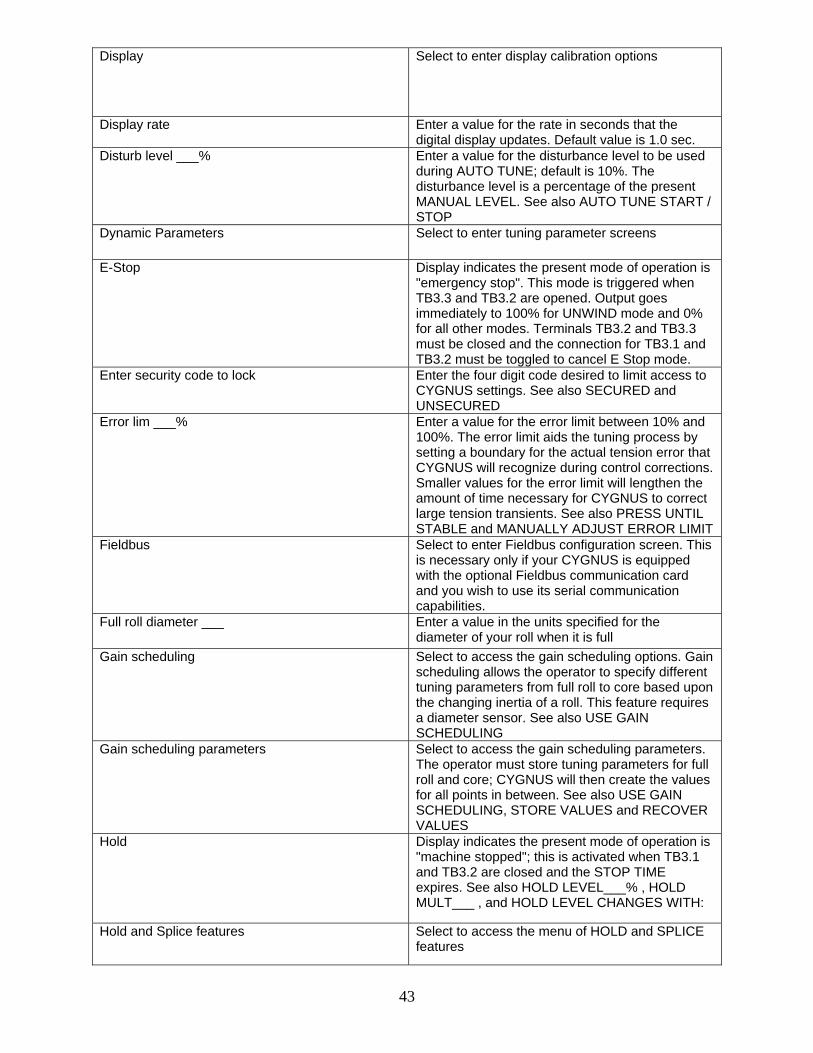
Display Select to enter display calibration options
Display rate Enter a value for the rate in seconds that the digital display updates. Default value is 1.0 sec.
Disturb level ___% Enter a value for the disturbance level to be used during AUTO TUNE; default is 10%. The disturbance level is a percentage of the present MANUAL LEVEL. See also AUTO TUNE START / STOP
Dynamic Parameters Select to enter tuning parameter screens
E-Stop Display indicates the present mode of operation is "emergency stop". This mode is triggered when TB3.3 and TB3.2 are opened. Output goes immediately to 100% for UNWIND mode and 0% for all other modes. Terminals TB3.2 and TB3.3 must be closed and the connection for TB3.1 and TB3.2 must be toggled to cancel E Stop mode.
Enter security code to lock Enter the four digit code desired to limit access to CYGNUS settings. See also SECURED and UNSECURED
Error lim ___% Enter a value for the error limit between 10% and 100%. The error limit aids the tuning process by setting a boundary for the actual tension error that CYGNUS will recognize during control corrections. Smaller values for the error limit will lengthen the amount of time necessary for CYGNUS to correct large tension transients. See also PRESS UNTIL STABLE and MANUALLY ADJUST ERROR LIMIT
Fieldbus Select to enter Fieldbus configuration screen. This is necessary only if your CYGNUS is equipped with the optional Fieldbus communication card and you wish to use its serial communication capabilities.
Full roll diameter ___ Enter a value in the units specified for the diameter of your roll when it is full
Gain scheduling Select to access the gain scheduling options. Gain scheduling allows the operator to specify different tuning parameters from full roll to core based upon the changing inertia of a roll. This feature requires a diameter sensor. See also USE GAIN SCHEDULING
Gain scheduling parameters Select to access the gain scheduling parameters. The operator must store tuning parameters for full roll and core; CYGNUS will then create the values for all points in between. See also USE GAIN SCHEDULING, STORE VALUES and RECOVER VALUES
Hold Display indicates the present mode of operation is "machine stopped"; this is activated when TB3.1 and TB3.2 are closed and the STOP TIME expires. See also HOLD LEVEL___% , HOLD MULT___ , and HOLD LEVEL CHANGES WITH:
Hold and Splice features Select to access the menu of HOLD and SPLICE features

44
Hold level ___% Enter a value from 0 - 100% that will dictate the control output while CYGNUS is in HOLD mode. The tension display will function normally during this time
Hold level changes with: diameter Toggle to change the HOLD LEVEL output according to the present diameter of the roll. This feature provides accurate hold levels that compensate for the changing weight of an unwinding roll and requires the DIAMETER SENSOR TYPE to be properly configured
Hold level changes with: diameter & tension Toggle to use both HOLD LEVEL CHANGES WITH TENSION and HOLD LEVEL CHANGES WITH DIAMETER
Hold level changes with: none Toggle to set output during HOLD mode using the HOLD LEVEL ___% parameter
Hold level changes with: output Toggle to set output during HOLD mode by multiplying the HOLD MULT___ with the last output before the STOP signal was received. This will compensate for the changing weight of an unwinding roll without requiring a diameter input
Hold level changes with: tension Toggle to change the HOLD LEVEL output by a scaled amount identical to changes made in the TENSION SETPOINT. This feature accommodates changing hold level requirements for different tension setpoints
Hold mult ___ Enter a value to manipulate the control output in HOLD mode when the HOLD LEVEL CHANGES WITH OUTPUT option is selected
Home Selecting this returns you to the home screen
I only Toggle to design a control loop with INTEGRATOR only
If stable and the above optimization has been done…
Display prompts the operator to perform manual optimization while the roll is near core
If stable, optimize first at full roll Display prompts the operator to perform manual optimization while the roll is full
Inertia comp Select to enter Inertia compensation options. Inertia compensation allows CYGNUS to account for the different characteristics of roll behavior with the weight of a full roll versus the weight of the roll at core to provide improved tension control while accelerating and stopping.
Integrator ___sec Enter a value for the integrator time, which is the amount of time elapsed between control corrections. A value that is too high will make the system less responsive to tension errors, while a value that is too low will make the system quick but unstable. Factory default setting is 2 seconds.
Is accel comp used? Toggle YES or NO to activate the acceleration compensation feature. This feature uses the parameters CORE WK2, ROLL WGT ___, CORE DIA ___, ROLL DIA ___, WIDTH ___, VELOCITY ___, and THRESHOLD ___% to adjust the control loop to provide improved tension control during the special conditions of acceleration and deceleration. A velocity sensor is required.
45
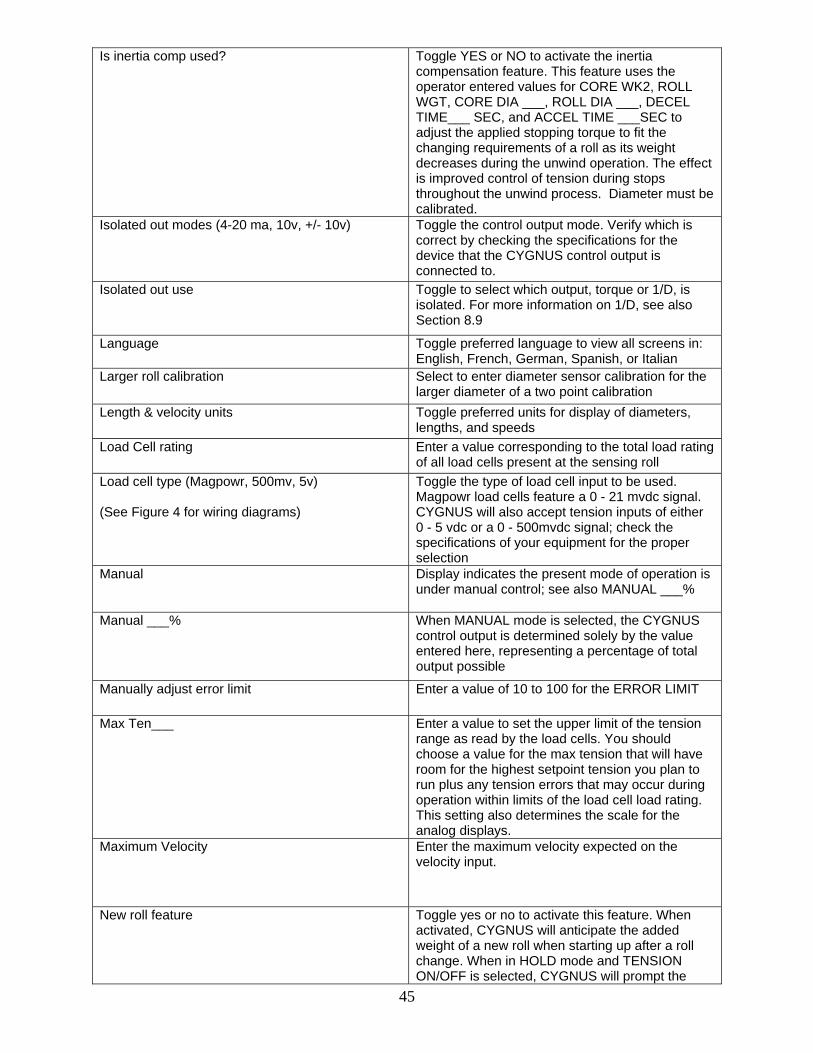
Is inertia comp used? Toggle YES or NO to activate the inertia compensation feature. This feature uses the operator entered values for CORE WK2, ROLL WGT, CORE DIA ___, ROLL DIA ___, DECEL TIME___ SEC, and ACCEL TIME ___SEC to adjust the applied stopping torque to fit the changing requirements of a roll as its weight decreases during the unwind operation. The effect is improved control of tension during stops throughout the unwind process. Diameter must be calibrated.
Isolated out modes (4-20 ma, 10v, +/- 10v) Toggle the control output mode. Verify which is correct by checking the specifications for the device that the CYGNUS control output is connected to.
Isolated out use Toggle to select which output, torque or 1/D, is isolated. For more information on 1/D, see also Section 8.9
Language Toggle preferred language to view all screens in: English, French, German, Spanish, or Italian
Larger roll calibration Select to enter diameter sensor calibration for the larger diameter of a two point calibration
Length & velocity units Toggle preferred units for display of diameters, lengths, and speeds
Load Cell rating Enter a value corresponding to the total load rating of all load cells present at the sensing roll
Load cell type (Magpowr, 500mv, 5v) (See Figure 4 for wiring diagrams)
Toggle the type of load cell input to be used. Magpowr load cells feature a 0 - 21 mvdc signal. CYGNUS will also accept tension inputs of either 0 - 5 vdc or a 0 - 500mvdc signal; check the specifications of your equipment for the proper selection
Manual Display indicates the present mode of operation is under manual control; see also MANUAL ___%
Manual ___% When MANUAL mode is selected, the CYGNUS control output is determined solely by the value entered here, representing a percentage of total output possible
Manually adjust error limit Enter a value of 10 to 100 for the ERROR LIMIT
Max Ten___ Enter a value to set the upper limit of the tension range as read by the load cells. You should choose a value for the max tension that will have room for the highest setpoint tension you plan to run plus any tension errors that may occur during operation within limits of the load cell load rating. This setting also determines the scale for the analog displays.
Maximum Velocity Enter the maximum velocity expected on the velocity input.
New roll feature Toggle yes or no to activate this feature. When activated, CYGNUS will anticipate the added weight of a new roll when starting up after a roll change. When in HOLD mode and TENSION ON/OFF is selected, CYGNUS will prompt the

46
operator to indicate whether a new roll is being added or if the machine was simply stopped part way through the roll
Non-isolated out use Toggle to select which output, torque or 1/D, is not isolated. For more information on 1/D, see also Section 8.9
Not allowed not running Display indicates that the feature you are attempting to access is only available when CYGNUS is in RUN mode. Check the HOME screen to verify which mode CYGNUS is currently in
Off Display indicates the present mode of operation is "tension off". The control output from CYGNUS is 0%
Optimize manually Select to enter manual optimization procedure. Follow the on-screen prompts to achieve proper tuning settings
Optimize with PI / PID Toggle DERIVATIVE TIME parameter active during OPTIMIZE MANUALLY. The operator must select the method before tuning
Out of round comp Select to access the out of round roll compensation configuration menu
Out of round enable Toggle to activate the out of round feature that will compensate for eccentric rolls in an UNWIND application. This feature requires an external RPM sensor
Out of round gain ___ Enter a value for the PROPORTIONAL GAIN tuning parameter to be used in the control loop while OUT OF ROUND COMPENSATION is active
Out of round max RPM Enter a value to limit the RPM sensor input in the event that the out of round roll compensation activity approaches the natural frequency of the system. This situation is unlikely, but will become evident if the braking action on the web begins to oscillate out of control during the unwind. If this happens, check the readout of the present roll RPM and set the OUT OF ROUND MAX RPM at some value below this reading.
Output ___% Display of the current output level from the CYGNUS at TB1.1 and TB1.2, TB1.3, or TB1.4 depending upon which output is utilized
Overall gain ___ Enter a value for the overall gain. This parameter is similar to the PROP GAIN in definition, however, it is always present and multiplied through the control signal regardless of other settings. Factory default is "1" and it is not normally recommended that you modify this unless you are using the GAIN SCHEDULING feature. In this case, the overall gain can be manipulated to improve stability at mid-roll.
Percent Taper ___% Enter a value to taper tension down as roll builds during REWIND mode. This will help reduce the pressures that build in rolls as consecutive layers are wound and can reduce or eliminate the unwanted effects such as crushed cores, starring and telescoping rolls.

47
Perform calibrate Select to continue with tension sensor calibration. Follow the on-screen prompts for the subsequent steps. See also Section 6.3
PI Toggle to utilize a control loop with PROPORTIONAL GAIN and INTEGRATOR. Manual tuning only.
PID Toggle to utilize a control loop with PROPORTIONAL GAIN, INTEGRATOR, and DERIVATIVE. Manual tuning only.
Precision calibration Select to enter load cell precision calibration procedure. This will require use of weights and a temporary web that mimics the normal web path around the sensing roll. This is recommended as the most accurate method of load cell calibration. See also Section 6.3
Press here to calibrate diameter Select 4 or 9 to match the ACTUAL READING ___ with CALIBRATE SETPOINT ___
Press here to calibrate RPM Select 4 or 9 to match the ACTUAL READING ___ RPM with CALIBRATE SETPOINT ___RPM
Press here to calibrate velocity Select 4 or 9 to match the ACTUAL READING ___ with CALIBRATE SETPOINT ___
Press until stable (decrease error lim) Press either 3 or 8 to decrease the ERROR LIMIT incrementally until the web tension becomes stable. Watch the ACTUAL TENSION display above as you adjust the ERROR LIMIT.
Program Select to enter programming screens
Prop gain ___ Enter a value for the proportional gain. This tuning parameter adds a correction factor that is proportional to the deviation from the tension setpoint. A higher value will make the system more responsive but a proportional gain that is too high will result in an unstable system. Factory default setting is "0"
Quick Stabilize Select to attempt to remedy an unstable condition by manipulating the error limit. This feature should be used if the default settings are causing extreme disturbances in the system. After stabilizing with this method, it is necessary to tune the system. See also Section 7.0
Rating Enter a value for the max combined load rating of your load cell(s) as specified by the manufacturer
Recover values Select to use the corresponding tuning parameters as your fixed tuning parameters if GAIN SCHEDULING is deactivated or if parameters are manually modified. It can also be used to recover AUTO TUNE measurements.
Rewind Toggle this selection for applications where CYGNUS is controlling a device that sets the tension in a rewind zone. See also Figure 1.
Roll dia ___ Enter a value for the diameter of your full roll
Roll wgt ___ Enter a value for the weight of your full roll

48
RPM Select to enter roll RPM sensor calibration. RPM sensor must be activated to continue; see also CONFIGURE I/O
RPM sensor type Toggle to activate an external RPM sensor. Check the specifications for the sensor to determine if its output is "pulse" or "voltage" type
Run Display indicates the present mode of operation is normal running status. TB3.1 and TB3.2 must be open and START TIME expired
Run/stop input Toggle to indicate if RUN/STOP will be triggered from TB3.1 & TB3.2 or by Fieldbus communication. See also FIELDBUS
Secured Select to enter security screen. When SECURED is displayed, all calibration and parameter settings are not accessible until unlocked by the proper four digit code; see also UNSECURED
Sensor type is set to "none" Display indicates the sensor you are attempting to access has not been configured correctly. See also CONFIGURE I/O
Setpoint Enter the desired tension value for your process that you wish to maintain during normal running conditions
Setup ___ Displays the number corresponding to the current setup. Selecting this will take you to the setup selection screen; see also CHANGE SETUP and COPY SETUP
Single point calibration Select to enter single point diameter sensor calibration
Smaller roll calibration Select to enter diameter sensor calibration for the smaller diameter of a two point calibration
Splice Display indicates the present mode of operation is "splicing"; see also SPLICE MULT___ and SPLICE FEATURE
Splice feature Toggle yes or no to activate this feature. When active, a switch closure of TB4.8 and TB4.6 will signal CYGNUS to enter SPLICE mode to manipulate the control output during a zero-speed splicing operation. See also SPLICE MULT ___
Splice input Toggle to indicate if SPLICE operation will be triggered from TB4.6 & TB4.8 or by Fieldbus communication. See also FIELDBUS
Splice mult Enter a value for the splice multiplier. This parameter behaves much like the HOLD MULTIPLIER except that it has acceleration and deceleration modifiers
Splice, Hld, Start, Stop Select for configuration of the automatic mode special condition options
Start Display indicates the present mode of operation is "starting"; activated when TB3.1 and TB3.2 are opened. See also START TIME___SEC
Start time ___ sec Enter a value based upon the amount of time it takes your machine to ramp up from stopped to steady state operation. If the tension spikes during this time, try increasing this START TIME value
49
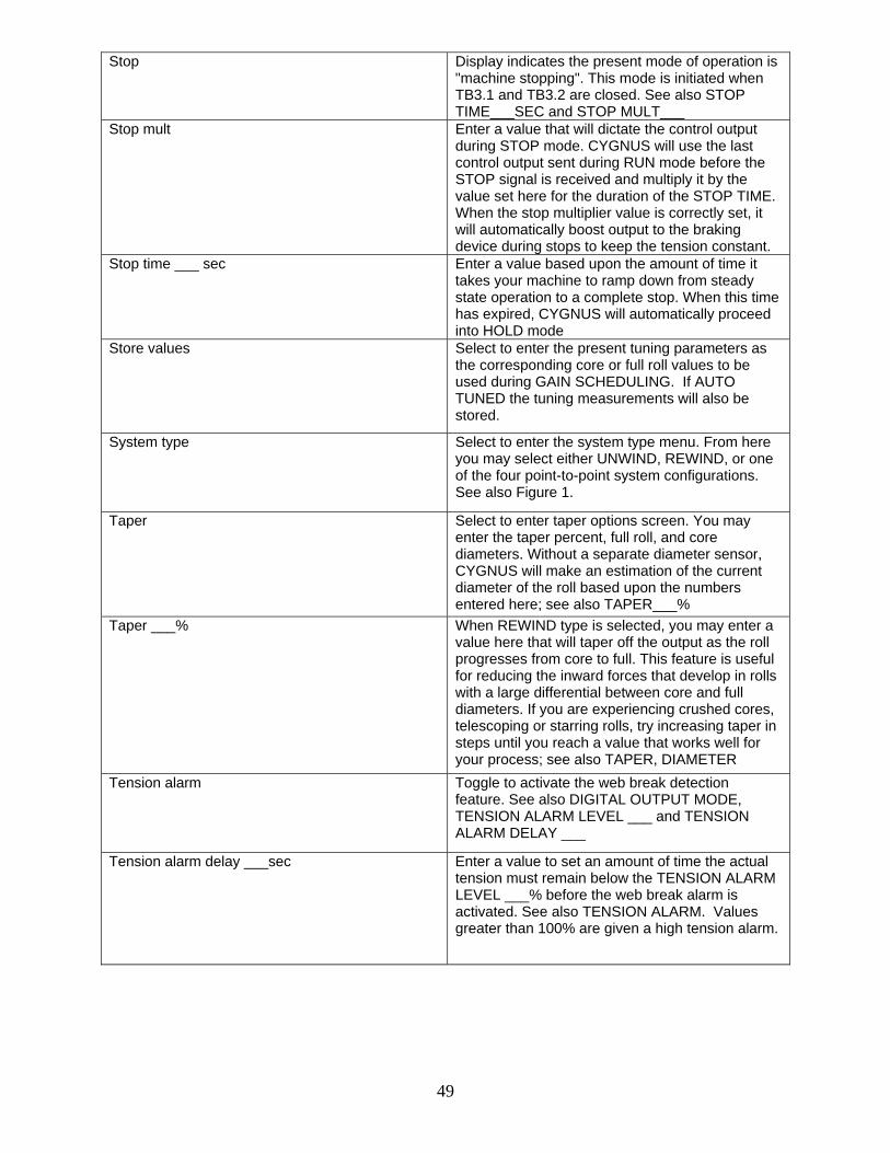
Stop Display indicates the present mode of operation is "machine stopping". This mode is initiated when TB3.1 and TB3.2 are closed. See also STOP TIME___SEC and STOP MULT___
Stop mult Enter a value that will dictate the control output during STOP mode. CYGNUS will use the last control output sent during RUN mode before the STOP signal is received and multiply it by the value set here for the duration of the STOP TIME. When the stop multiplier value is correctly set, it will automatically boost output to the braking device during stops to keep the tension constant.
Stop time ___ sec Enter a value based upon the amount of time it takes your machine to ramp down from steady state operation to a complete stop. When this time has expired, CYGNUS will automatically proceed into HOLD mode
Store values Select to enter the present tuning parameters as the corresponding core or full roll values to be used during GAIN SCHEDULING. If AUTO TUNED the tuning measurements will also be stored.
System type Select to enter the system type menu. From here you may select either UNWIND, REWIND, or one of the four point-to-point system configurations. See also Figure 1.
Taper Select to enter taper options screen. You may enter the taper percent, full roll, and core diameters. Without a separate diameter sensor, CYGNUS will make an estimation of the current diameter of the roll based upon the numbers entered here; see also TAPER___%
Taper ___% When REWIND type is selected, you may enter a value here that will taper off the output as the roll progresses from core to full. This feature is useful for reducing the inward forces that develop in rolls with a large differential between core and full diameters. If you are experiencing crushed cores, telescoping or starring rolls, try increasing taper in steps until you reach a value that works well for your process; see also TAPER, DIAMETER
Tension alarm Toggle to activate the web break detection feature. See also DIGITAL OUTPUT MODE, TENSION ALARM LEVEL ___ and TENSION ALARM DELAY ___
Tension alarm delay ___sec Enter a value to set an amount of time the actual tension must remain below the TENSION ALARM LEVEL ___% before the web break alarm is activated. See also TENSION ALARM. Values greater than 100% are given a high tension alarm.

50
Tension alarm level ___% Enter a value to determine when CYGNUS will send a signal through TB3.4 & TB3.5 to indicate that a web break has occurred. The value entered represents a percentage of deviation below the tension SETPOINT. See also TENSION ALARM. A “VALUE GREATER THAN 100%” will provide a HIGH TENSION ALARM.
Tension decreases, clutch or motor For point-to-point applications using a clutch or motor and drive, select 5 if the controlled device is located upstream from the sensor placement or 0 if it is downstream from the sensor placement. See also Figure 1.
Tension increases, brake or regen drive For point-to-point applications using a brake or regenerative drive, select 3 if the braking device is located upstream from the sensor placement or 8 if it is downstream from the sensor placement. See also Figure 1.
Tension on / off Toggles the output between 0% for OFF and under the control of all other modes for ON. When TOGGLE selected, TB4.7 also toggles.
Tension on/off mode Toggle to indicate if TENSION ON/OFF will be triggered from keypad (toggle) or TB4.7 (level).
Tension units Toggle preferred tension measurement units. This will be applied to any displays related to tension measurements
Threshold ___% Enter a value for the acceleration threshold. This parameter determines a minimum amount of change in web velocity before the ACCELeration COMPensation feature activates. A lower value here will make the feature more sensitive to changes in speed.
Tuned at core Select STORE VALUES to save current tuning parameters as the core tuning parameters; select RECOVER VALUES to return to these same stored settings at any time if they have been changed. See also USE GAIN SCHEDULING.
Tuned at full roll Select STORE VALUES to save current tuning parameters as the full roll tuning parameters; select RECOVER VALUES to return to these same stored settings at any time if they have been changed. See also USE GAIN SCHEDULING
Units & Language Select to view options for the units of measure and language to be applied to all CYGNUS screens
Unsecured Select to enter security screen. A four digit code may be entered to lock all calibration and parameter settings and prevent manipulation by unauthorized users. The same four digit code must be entered to unlock and grant access to these settings. When UNSECURED is displayed, any four digit code may be used regardless of the last code used; see also SECURED
Unwind Toggle this selection for applications where CYGNUS is controlling a device that sets the tension in an unwind zone. See also Figure 1.

51
Use gain scheduling Toggle to activate the gain scheduling feature that will utilize different tuning parameters from full roll to core. This feature requires a diameter sensor to function and will compensate for changing tuning requirements throughout the unwind or rewind process by using the settings you provide at full roll and core and interpolating the values for every diameter point in between.
Velocity sensor type Toggle to activate an external velocity sensor. Check the specifications for the sensor to determine if its output is "pulse" or "voltage" type
Velocity___ Enter a value for the steady state line speed of your machine
Voltage between TB6-1 & 2 Display of the voltage present corresponding to the load cell signal input. This is useful for evaluating the performance of load cells by comparing actual vs. expected return signal for a given applied force.
Voltage on TB6-1 Display of the voltage present corresponding to the load cell signal input. This is useful for evaluating the performance of load cells by comparing actual vs. expected return signal for a given applied force.
Voltage on TB6-2 Display of the voltage present corresponding to the load cell signal input. This is useful for evaluating the performance of load cells by comparing actual vs. expected return signal for a given applied force.
Sensor Voltage Display of actual voltage present at the sensor input terminal
Web Velocity Select to enter calibration of an external web speed sensor. Web speed sensor input must be active; see also CONFIGURE I/O
Web Width___ Select to edit the current web width for use in tension setpoint calculation when TENSION UNITS of PLI, kg/cm, gm/mm, oz/in, or N/cm are selected. Also used for changing INERTIA values.
Weightless calibration Select to calibrate load cells without using weights. This procedure depends on correct entries for the LOAD CELL RATING and WRAP ANGLE to provide accurate readings
Width ___ Enter a value for the web width
Wrap angle Enter a value for the wrap angle formed by the web around the sensing roll. Example: A web that comes straight up, wraps around the roll, and continues straight down is a 180 degree wrap. A web that comes straight up, wraps around the roll, and continues on to the right is a 90 degree wrap.
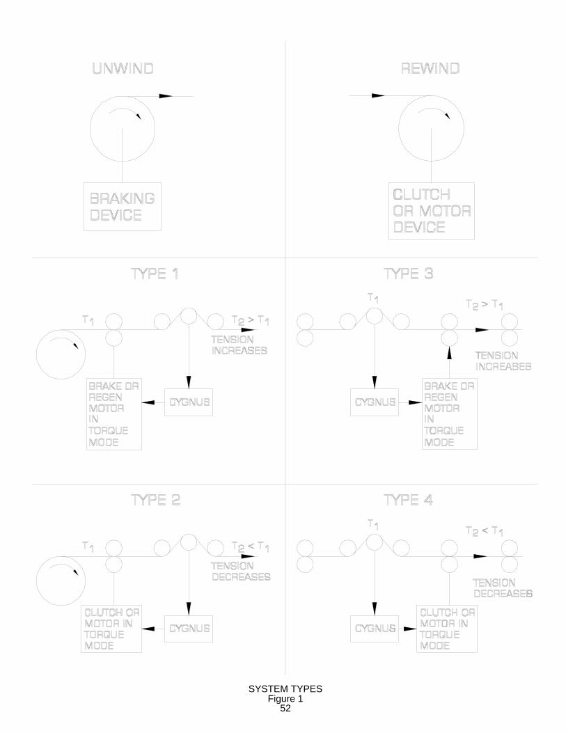
Figure 1SYSTEM TYPES
52

COMMKIT-PB, ProfibusCOMMKIT-DN, DeviceNet
Figure 2
Fieldbus Card
COMMKIT-EN, EthernetFieldbus Card Installation
53

FENTON, MO 63026 - USA
CYGNUS WIRING DIAGRAM
L1115/230 VAC
L2 P.E.0-10VCOMOUTPUT
LOADCELLOPEN FOR RUN
OPEN FORE-STOP
FENTON, MO 63026 - USA
MAGPOWR
(SEE FIGURE 4FOR DETAIL)
Figure 354

5 Volt (DC)Tension Signal
+-
S- P- P+
TB6
S+
Two MagpowrLoad Cells
WH
ITE
BLA
CK
GR
EE
N
RE
D
TB5
GN
D
Two Half Bridge500mv Load Cells
BLA
CK
WH
ITE
RE
D
GR
EE
N
WH
ITE
RE
D
BLA
CK
GR
EE
N
1 2 3 4
BLA
CK
S-
WH
ITE
S+
1
GR
EE
N
RE
D
32
P-
4
P+
One MagpowrLoad Cell
TB6
GR
EE
N
WH
ITE
BLA
CK
RE
D
P+
1
S+ P-
2
S-
3 44 1
500mv Load Cell
S+ P+P-
2
S-
3 4
One Half Bridge
TB6TB6
3 421
S+
TB6
S-
P-
P+
TB5
4
TB5
4
PrecisionBridgeCompletionResistors(ContactLoad CellManufacturerfor Values)
LOAD CELL WIRING DETAILFigure 4
55
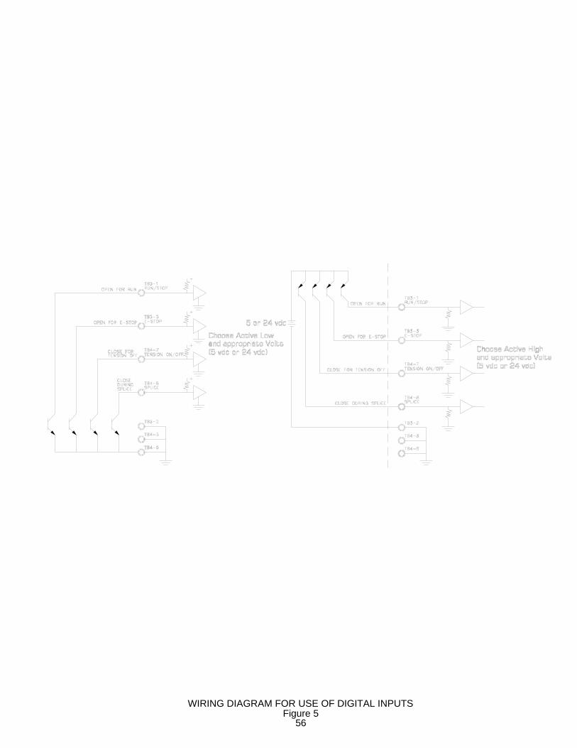
WIRING DIAGRAM FOR USE OF DIGITAL INPUTSFigure 5
56

GroundDesired TensionSetup Select
Shield
200Ω
+10 vdc (External Power Supply)
Ground
Shield
TB4-1, TB4-2,TB5-1 or TB5-3
TB4-3, TB4-6,TB5-2 or TB5-4
Setup Select
Setup 1
Setup 10
Ground
200Ω
Setup Select
Setup 1
+5 vdc (External Power Supply)
Setup 6
Shield
PowerSupply
PowerSupply
+5 vdc (Tension Sensor P+)
OR
Desired Tension
Shield
TB6-4(+5 vdc)
Ground
+5 vdc(Tension
Sensor P+)
1KΩ
200Ω
200Ω
200Ω
200Ω
200Ω
200Ω
200Ω
200Ω
200Ω
200Ω
200Ω
200Ω
+10 vdc (External Power Supply) Power
Supply
OR
AnalogGround
Analog Output0 to +10 vdc
Analog Output0 to +10 vdc
TB4-3, TB4-6,TB5-2 or TB5-4TB4-1, TB4-2,TB5-1 or TB5-3
TB5-1 or TB5-3TB4-1, TB4-2,
VOLTAGE TABLE FOR REMOTE SETUP SELECTTable 2
TB4-1, TB4-2,TB5-1 or TB5-3TB4-3, TB4-6,TB5-2 or TB5-4
TB4-3, TB4-6,TB5-2 or TB5-4
TB4-1, TB4-2,TB5-1 or TB5-3
TB6-4(+5 vdc)
Figure 6WIRING DIAGRAMS FOR REMOTE TENSION SETPOINT
Figure 7WIRING DIAGRAMS FOR REMOTE SETUP SELECT
0+0.251±0.252±0.253±0.254±0.255±0.256±0.257±0.258±0.259±0.25
6
10987
54321
Setup NumberInput Voltage
57

CYGNUS-E WIRING LAYOUT
FENTON, MO 63026 - USA
TENSION SENSORS
AUXILLARY WIRING
POWER
CYGNUS-E WITH DOOR CLOSED
CYGNUS-E WITH DOOR OPEN
PS90/PS24
REFERENCEFIGURE 3FOR WIRING
Figure 858
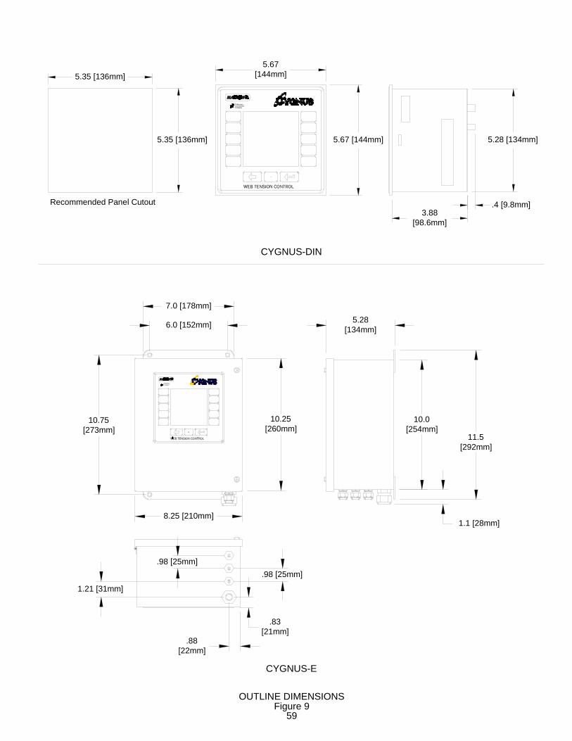
5.67[144mm]
5.67 [144mm]
3.88[98.6mm]
5.28 [134mm]
A Maxcess International Company
.4 [9.8mm]Recommended Panel Cutout
5.35 [136mm]
5.35 [136mm]
5.28[134mm]
10.0[254mm]
11.5[292mm]
1.1 [28mm]
6.0 [152mm]
10.25[260mm]
10.75[273mm]
.88[22mm]
8.25 [210mm]
7.0 [178mm]
.83[21mm]
1.21 [31mm]
.98 [25mm].98 [25mm]
A Maxcess International Company
CYGNUS-DIN
CYGNUS-E
OUTLINE DIMENSIONSFigure 9
59

CYGNUS® Specifications
Supply Voltage 115 or 230 volts rms, ±10%, 24 VA Supply Frequency: 50 or 60 cycles per second, sinusoidal
Fuses: F1, F2 1.6 amp, Littelfuse Part No. 21601.6, or Wickmann Part No. 19194-053-FS
Enclosure
CYGNUS-DIN Front Panel IP65 (IEC529) Enclosure IP20 (IEC529)
CYGNUS-E IP65 (IEC529) Climatic Class: 3K3 (EN60721) Temperature Range: Operating CYGNUS-DIN 0°C to 50°C CYGNUS-E 0°C to 40°C Storage -30°C to +80°C Relative Humidity 5% to 85% Pollution Degree: 2 (IEC664-1) Altitude: 0 to 2000 m Compatible Residual Current Devise Types: A or B (IEC755) Worst Case Fault Current: 1.6 amp Inputs: Load cell 2.1 millivolts/volt using +5 and -5 VDC (10 VDC)
across one 350 ohm sensor or two 350 ohm sensors in parallel,
or 100 millivolts/volt using 5 volts across one 120 ohm full bridge, or 0 to +5 VDC analog
Diameter 0 to +10 VDC analog
Velocity / RPM 0 to +10 volts analog, or
0.01 to 50,000 pulses per second, 5 VDC or 24 VDC logic
Auxiliary Input 0 to +10 VDC, 1 mADC maximum E-Stop switch closure or 5 VDC or 24 VDC logic, 8 mADC maximum Run/Stop switch closure or 5 VDC or 24 VDC logic, 8 mADC maximum Tension Off switch closure or 5 VDC or 24 VDC logic, 8 mADC maximum Format switch closure or 5 VDC or 24 VDC logic, 8 mADC maximum Splice switch closure or 5 VDC or 24 VDC logic, 8 mADC maximum Outputs: Torque 0 to +10 VDC., 1 mADC maximum
4 to 20 mADC, 500 ohms maximum -10 to +10 VDC, 1 mADC maximum
Inverse Diameter 0 to +10 VDC, 1 mADC maximum Low Tension dc solid state relays, 100 mADC, 30 VDC maximum or TTL levels Tension status dc solid state relay, 100 mADC, 30 VDC maximum or TTL levels Tension Reference 0 to 1 mADC or 0 to +10 VDC analog