instruction manual colorplus ex sigrist absorption …
TRANSCRIPT

INSTRUCTION MANUAL
ColorPlus Ex
SIGRIST Absorption Measuring
Instrument
with SIREL SMD / SIREL Ex
SIGRIST-PHOTOMETER AG
Hofurlistrasse 1
CH-6373 Ennetbürgen
Switzerland
Phone: +41 (0)41 624 54 54
Fax: +41 (0)41 624 54 55
E-mail: [email protected]
Internet: www.photometer.com
Document Number: 10210E Version: 5 Valid from: 2019-09-01

© Sigrist-Gruppe, Subject to change without notice 09/19

Instruction Manual ColorPlus Ex
10210E/5 i
Contents
1 Instrument Description ....................................................................... 5 1.1 General view of a bypass measuring setup ...................................... 5 1.2 General view of an inline measuring setup....................................... 5 1.3 Scope of supply and accessories ................................................... 6 1.4 Purpose and conformity................................................................ 7 1.5 Marking of the Product ................................................................. 8 1.6 Technical data .......................................................................... 10
2 Safety Rules ................................................................................... 13
3 Installation/start-up .......................................................................... 14 3.1 Photometer installation for the bypass version ............................... 14 3.2 Photometer installation in inline housing ....................................... 15
3.2.1 Sectional view of measuring setup ...................................... 16 3.2.2 Installation with shortened path length ................................. 17
3.3 Installation of the cooling system (option) ..................................... 18 3.4 Installation of user-specific versions ............................................. 18 3.5 Installation of the control units SIREL SMD ................................... 19 3.6 Installation of the SIREL Ex control unit ........................................ 21 3.7 Electrical connections ................................................................ 22
3.7.1 Voltage equalizing cable connection on the flow cell housing .. 22 3.7.2 Connecting the control unit SIREL ....................................... 22 3.7.3 Opening the SIREL SMD .................................................... 23 3.7.4 Opening the SIREL Ex housing ............................................ 23 3.7.5 Establish SIREL SMD/Ex electrical connections ...................... 24
3.8 Initial start-up ........................................................................... 26
4 Operation ....................................................................................... 27 4.1 Operating elements and display SIREL SMD .................................. 27
4.1.1 Control components and display of the SIREL Ex ................... 29 4.2 Normal operation (operating mode) .............................................. 30 4.3 Service mode ............................................................................ 31 4.4 Set your language ..................................................................... 31 4.5 Set the measuring range ............................................................. 32 4.6 Configure the channels ............................................................... 33 4.7 Set the relay functions ............................................................... 33 4.8 Set the limits ............................................................................ 34 4.9 Set the access code .................................................................. 36
5 Servicing ........................................................................................ 37 5.1 Service schedule ....................................................................... 37 5.2 100% adjustment of the photometer ............................................ 38 5.3 Functional check with reference glass .......................................... 39 5.4 Replacement of the desiccant in the sensor head ........................... 41 5.5 Replacement of the desiccant in the transmitter ............................. 43 5.6 Replacement of the desiccant in the receiver ................................. 44 5.7 Cleaning/replacement of the flow cell windows in bypass flow cells . 45 5.8 Cleaning/replacement of the flow cell windows on the Varivent® flow
cell 46 5.9 Replacement of the UV light source ............................................. 50
6 Troubleshooting ............................................................................... 52

Instruction Manual ColorPlus Ex
ii 10210E/5
6.1 Pinpointing the cause of a malfunction ......................................... 52 6.2 Fault messages ......................................................................... 52 6.3 Warnings ................................................................................. 54 6.4 Information .............................................................................. 55 6.5 Customer service information ..................................................... 55
7 Taking Out of Service/storage ........................................................... 57
8 Packing/Transport ........................................................................... 58
9 Disposal ......................................................................................... 59
10 Spare Parts .................................................................................... 60
11 Appendix ....................................................................................... 61
12 Index ............................................................................................. 63

Instruction Manual ColorPlus Ex
10210E/5 iii
Foreword
This Instruction Manual describes the basic functions for operating the
ColorPlus Ex. It is addressed to all persons who are responsible for operation
of the instrument.
Operate the instrument only after having familiarized yourself with the
contents of this Instruction Manual. In particular, be sure to study the section
on safety rules before starting operation.
Doc. No. Title Contents
10211E Reference
Handbook
Detailed menu functions and worksteps for
trained personnel
10213E Service Manual Repair and modification instructions for service
technicians
10212E Brief Instructions Most important functions and complete menu
structure
10662E White Paper Technical Instruction of the interfaces Modbus
and Profibus DP
11044E SIREL Ex
Instruction Manual
Contains additional information about the SIREL
Ex control unit
Important information
Action
Supplementary information
Extremely dangerous voltage
Warning: explosion hazard (CAN BE FATAL!)
Separate disposal of electrical and electronic equipment
Further
documentation
Symbols used in this
Manual

Instruction Manual ColorPlus Ex
iv 10210E/5

Instruction Manual ColorPlus Ex
10210E/5 5
1 Instrument Description
1.1 General view of a bypass measuring setup
Figure 1: General view of a bypass measuring setup
Pos. Name
1 Control unit
Example with
SIREL SMD
2 Transmitter
3 Flow cell
4 Receiver
5 Photometer
6 Ex-zone
7 Transmitter-receiver
connecting cable
8 Photometer-SIREL
connecting cable
9 Partition
10 Non-Ex zone
1.2 General view of an inline measuring setup
Figure 2: General view of an inline measuring setup
Pos. Name
1 Control unit
Example with
SIREL SMD
2 Transmitter
3 Flow cell
4 Receiver
5 Photometer
6 Ex-zone
7 Transmitter-receiver
connecting cable
8 Photometer-SIREL
connecting cable
9 Partition
10 Non-Ex zone

Instruction Manual ColorPlus Ex
6 10210E/5
1.3 Scope of supply and accessories
Units Name Alternatives Optional
1 Photometer ColorPlus Ex for bypass, for
Varivent® installation (inline) or in
user-specific version
1 Control unit
SIREL SMD
or
SIREL Ex
SIREL, SIREL robust
85..264 VAC, 24 VDC
with
SITRA/SIBUS
1 Flow cell - bypass
- Varivent®
- user-specific
1 Bus coupler Profibus DP X
1 Cooling Depends on medium temperature
and ambient temperature
X
1 Wrench for
dismantling flow cell
windows
SW32 (for bypass flow cell) or
OPL bit wrench (for Varivent®
version)
1 Housing key
(118771)
Only for SIREL Ex
1 Instruction Manual English, German, French
1 Reference
Handbook
English, German
1 Brief Instructions English, German, French
1 Parameter list English, German
Standard scope
of supply

Instruction Manual ColorPlus Ex
10210E/5 7
1.4 Purpose and conformity
Use of the photometer for purposes other than that for which it was designed
can produce incorrect measuring results, possibly with consequential damage
to the process and damage to the photometer itself.
Installation and operation of the control unit and any supplementary
components in areas at risk of explosion is prohibited (DANGER OF FATAL
INJURY)!
If a control unit SIREL Ex is used to read the manufacturer's documentation
11044DEF advance.
The photometer and its periphery are designed for measuring the absorption of
liquids and gases in areas at risk of explosion designated Zone 1, (Ex d IIC
T3/T4/T5/T6 Ga/Gb).
The photometer complies with the following standards for electrical equipment
and for areas at risk of explosion:
EN 60079-0:2009 General requirements
EN 60079-1:2007 Instrument protection with pressure-proof
encapsulation “d”
EN 60079-26:2007 Operating materials with instrument
protection level (EPL) Ga
EN 60079-28:2007 Protection of equipment and transmission
systems which work with optical emissions
Directive 94/9/EC
Tabelle 1: Standards
The photometer possesses the following certifications:
EC-Type Examination Certificate BVS 10 ATEX E 102 X
BVS 17 ATEX ZQS/E422
IECEx BVS 13.0058X
The current rules of engineering practice were observed in its design and
manufacture. They meet the usual directives with regard to safety and the
obligation to exercise due care.
The photometer and the control unit comply with the electromagnetic
compatibility (EMC) requirements applicable within the European Union (EU)
and with the Low Voltage Directives (LVD) and carry the CE mark.
Use in accordance
with design purpose

Instruction Manual ColorPlus Ex
8 10210E/5
1.5 Marking of the Product
The electrical connection figures and the serial number of the control unit are
shown on the sticker at the bottom left:
Figure 3: Plates for the serial number and the
electrical connection figures.
Figure 4: Photometer rating plate.
Figure 5: Position of the SIGRIST rating plate on the SIREL Ex
X: rating plate of the
manufacturer ( SIREL Ex
Instruction Manual)

Instruction Manual ColorPlus Ex
10210E/5 9
The photometer rating plate provides the following information:
Figure 6: Information on identification plate
Pos. Name
1 Manufacturer
2 Instrument type
3 Serial number
4 Conformity data
5 Ex protection type
6 Temperature
classes
7 Ambient
temperature
8 EC Type
Examination
Certificate
9 Warning
You can also consult the photometer’s serial number in the menu
* SYSTEM INFO * ( Reference Handbook).

Instruction Manual ColorPlus Ex
10 10210E/5
1.6 Technical data
Measuring principle: Absorption at 1 .. 3 different wavelengths: 254, 313
or 365 .. 700nm
Measuring span: 0 .. 0.05 E to 0 .. 3 E
Resolution: 0.001 E
Reproducibility: 1 %
Ambient temperature: -20 .. 50°C
Medium temperature: -20 .. 195° C
Cooling medium: minimum 0.17 l/min @ 10°C
Cooling: Cooling necessary
Absorption
measurement

Instruction Manual ColorPlus Ex
10210E/5 11
Operating voltage: 24 V DC (from control unit)
Interfaces: Modbus / with optional bus coupler Profibus DP
Flow cell
- bypass flow cell
Stainless steel 1.4435,
connections G ¼” female thread
- inline flow cell Varivent® housing of stainless steel 1.4404,
DN 40 – 150.
- user-specific
(inline flow cell)
Titanium, Hastelloy, PVDF etc.
Enclosure: Aluminum AlSi1MgMn, painted
Dimensions: Detailed dimension drawing: see Section 11
Weight: About 10 kg (not including flow cell)
Degree of protection: IP65
Type of Ex
protection/temperature
class:
Ex d IIC T3/T4/T5/T6 Ga/Gb, temperature class
dependent upon the temperature of the medium:
Medium temperature Temperature
class
-20 .. +80° C T6
-20.. +95° C T5
-20.. +130° C T4
-20 ..+195° C T3
Operating voltage: 85 .. 264 V; 47 .. 63 Hz or 24 VDC; 25 W
Space required: SIREL: 200 mm x 157 mm x 96 mm
SIREL robust: 220 mm x 160 mm x 90 mm
Detailed dimension drawing: see Section 11
Weight: SIREL: about 1.5 kg
SIREL robust: about 2.0 kg
Degree of protection: IP65
Connections: 0/4 .. 20 mA, max. 600 , max. 24 V, with
electrical isolation, max. 50V against earth
Relay contacts max. 250 VAC, max. 4 A
Digital inputs and outputs max. 5 V
Photometer
SIREL SMD/robust

Instruction Manual ColorPlus Ex
12 10210E/5
Service voltage 85 .. 264 V, 47 .. 63 Hz
Mains switch None
Dimensions 320 mm x 645 mm x 203 mm
Detailed dimension drawing see Section 11
Weight Approx. 25 kg
Protection type IP66
Ambient temperatures -20°C to +50°C
Connections See SIREL SMD
Additional technical data of the SIREL Ex is provided in Instruction Manual
11044DEF.
SIREL Ex

Instruction Manual ColorPlus Ex
10210E/5 13
2 Safety Rules
The symbols used in this Manual and on the photometer draw attention to the
following safety steps or precautions:
WARNING: EXPLOSION HAZARD (CAN BE FATAL)!
Thoughtless action can result in explosions! Before undertaking maintenance
work, always consult the Instruction Manual!
DANGER (BLACK ON YELLOW)
Warning: general source of danger. This symbol marks areas or manipulations
requiring the observance of special safety rules, which are specified in this
Instruction Manual.
VOLTAGE (BLACK ON YELLOW)
Warning: dangerous voltage. This marks live parts with voltages higher than
48 V AC or 65 V DC, which can cause electric shocks. In this case observe
the safety precautions and safe behavior prescribed in this Instruction Manual.
Before starting up the instrument, be absolutely sure to observe these
requirements:
To avoid disabling the type of protection, make sure no mechanical or
electrical modifications are carried out on the instrument or its parts.
Only properly instructed personnel are allowed to open and close the
photometer.
Carry out the operating steps contained in this documentation exactly in
the order stated. They are marked by the symbol in the margin.

Instruction Manual ColorPlus Ex
14 10210E/5
3 Installation/start-up
3.1 Photometer installation for the bypass version
The photometer must be installed in the horizontal position. To make it
possible to vent the flow cell properly, make sure the medium outlet is on top.
Action
1. Fasten the photometer horizontally to a
wall with four screws on fastening plate
(A). The transmitter (B) must be on the
right, the receiver (C) on the left.
2. Now connect the sample inlet and
outlet.
D: Medium inlet
E: Medium outlet
Mounting of the
bypass version

Instruction Manual ColorPlus Ex
10210E/5 15
3.2 Photometer installation in inline housing
The photometer can be installed using a standardized inline housing (Varivent®
or equivalent) in either vertical or horizontal product pipes.
The groove (A) on the transmitter and receiver must be installed pointing
upward!
Be sure to install the ColorPlus Ex so the transmitter and receiver are
positioned horizontally opposite each other! Only install a housing that
makes this possible!
The photometer must be installed in the pipe at least 2 m away from sight
glasses or other sources of stray light.
Figure 7: Installation in vertical product
pipes. Figure 8: Installation in horizontal product
pipes.
Installation position

Instruction Manual ColorPlus Ex
16 10210E/5
3.2.1 Sectional view of measuring setup
For detailed dimension drawings of ColorPlus Ex, refer to Section 11.
The inline housing is flanged into the pipe.
Pos. Name
1 Receiver
2 Adapter ring
3 Flow cell window
4 Hinged ring
5 Transmitter
6 Inline housing
7 Path length
shortener OPL bit
8 Leakage protector
Figure 9: Sectional view of ColorPlus Ex

Instruction Manual ColorPlus Ex
10210E/5 17
3.2.2 Installation with shortened path length
The ColorPlus Ex is delivered for installation in an inline housing with a
shortened path length (7) on both sides. The path length shorteners (OPL bits)
with flow cell window (3), matching leakage protector (8) and adapter ring (2)
are installed at the factory to meet the customer’s requirements.
Action Remarks
1. Insert the completely assembled transmitter /
receiver (including flow cell window (3),
adapter ring (2), leakage protector (8) and
screwed-on OPL bit) into the receptacle of the
inline housing.
The groove (A) on transmitter and receiver
must be installed pointing upward!
2. Fasten the transmitter / receiver with the
hinged ring (4) and tighten nut (A).
Mounting of
transmitter and
receiver

Instruction Manual ColorPlus Ex
18 10210E/5
3.3 Installation of the cooling system (option)
Figure 10: Cooling water connection.
Pos. Name
1 Direction of flow of
the cooling water
2 Cooling water
outlet transmitter
3 Transmitter
4 Cooling water inlet
transmitter
5 Inlet tube
6 Connecting tube
between
transmitter and
receiver
7 Cooling water inlet
receiver
8 Receiver
9 Cooling water
outlet receiver
10 Outlet tube
3.4 Installation of user-specific versions
For the installation of user-specific versions, refer to the drawing in
Section 11.

Instruction Manual ColorPlus Ex
10210E/5 19
3.5 Installation of the control units SIREL SMD
Do not install or operate the control unit or any supplementary components in
areas at risk of explosion (CAN BE FATAL)!
The control units can be mounted right on the wall, on a mounting frame or on
a stand.
The standard cable supplied is 5 m long. This ensures that the control unit will
be positioned close to the photometer.
Pos. Name
1 Photometer
2 SIREL
control unit
3 Non Ex-zone
4 Partition
5 Ex-zone
Figure 11: Control unit position with standard cable
For distances longer than 5 m it is necessary to insert an additional Ex-tested
terminal box between photometer and control unit. This permits quick
connection and disconnection of the photometer and control unit.
Pos. Name
1 Photometer
2 Ex-tested
terminal box
3 SIREL control
unit
4 Non Ex-zone
5 Partition
6 Ex-zone
Figure 12: Arrangement of control units located at distances longer than 5 m
Mounting SIREL
Distance up to 5 m
Distances longer
than 5 m – variant 1
Instruction Manual ColorPlus Ex
20 10210E/5
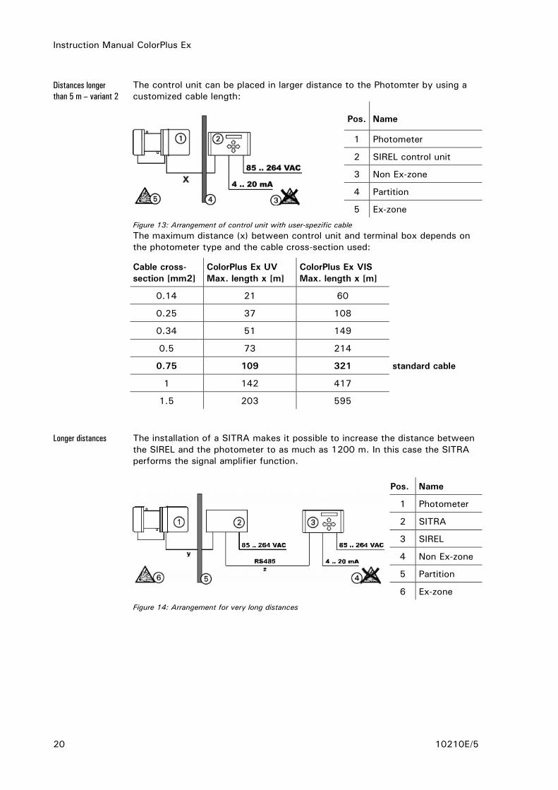
The control unit can be placed in larger distance to the Photomter by using a
customized cable length:
Pos. Name
1 Photometer
2 SIREL control unit
3 Non Ex-zone
4 Partition
5 Ex-zone
Figure 13: Arrangement of control unit with user-spezific cable
The maximum distance (x) between control unit and terminal box depends on
the photometer type and the cable cross-section used:
Cable cross-
section [mm2]
ColorPlus Ex UV
Max. length x [m]
ColorPlus Ex VIS
Max. length x [m]
0.14 21 60
0.25 37 108
0.34 51 149
0.5 73 214
0.75 109 321 standard cable
1 142 417
1.5 203 595
The installation of a SITRA makes it possible to increase the distance between
the SIREL and the photometer to as much as 1200 m. In this case the SITRA
performs the signal amplifier function.
Pos. Name
1 Photometer
2 SITRA
3 SIREL
4 Non Ex-zone
5 Partition
6 Ex-zone
Figure 14: Arrangement for very long distances
Distances longer
than 5 m – variant 2
Longer distances

Instruction Manual ColorPlus Ex
10210E/5 21
The maximum distance (y) between SITRA and photometer depends on the
photometer type and the cable cross-section used:
Cable cross-
section [mm2]
ColorPlus Ex UV
Max. length y [m]
ColorPlus Ex VIS
Max. length y [m]
0.14 16 48
0.25 30 87
0.34 41 119
0.5 59 171
0.75 87 256 standard cable
1 114 333
1.5 162 476
The maximum distance (z) between SITRA and control unit depends on the
cable cross-section used:
Cable cross-section [mm2] ColorPlus Ex UV + VIS
Max. length z [m]
0.14 471
0.25 844
0.34 1161
0.5 1200
0.75 1200 standard cable
1 1200
1.5 1200
3.6 Installation of the SIREL Ex control unit
Please consult manufacturer documentation 11044DEF when installing the
SIREL Ex.
A detailed dimension drawing of the SIREL Ex is in Section 11.
Refer to the table in Section 3.5 for distance dependency on cable cross-
section.

Instruction Manual ColorPlus Ex
22 10210E/5
3.7 Electrical connections
3.7.1 Voltage equalizing cable connection on the flow cell housing
It is absolutely necessary for the flow cell housing to be connected to the
voltage equalizing cable!
The following rules apply for the different versions:
In the case of the inline version, the piping system including the Varivent®
housing must be connected to the voltage equalizing cable.
In the case of the bypass version, the voltage equalizing cable must be
connected to the designated earthing point on the transmitter enclosure.
In the case of user-specific flow cells, the voltage equalizing cable must be
connected to the designated earthing point on the transmitter enclosure if the
material suited.
3.7.2 Connecting the control unit SIREL
Connecting live conductors is extremely dangerous, and parts of the
installation can be damaged. Always observe the local codes when performing
electrical installation work.
In addition, observe the following rules:
It is absolutely necessary to connect the protective earth conductor.
Because the instrument has no mains switch, a suitable disconnection
device (switch, plug) must be provided near the mains connection.
If malfunctions cannot be eliminated, take the instrument out of service
and take precautions against it being put back into service inadvertently.
Inline version
Bypass version
User-specific flow
cells
Instruction Manual ColorPlus Ex
10210E/5 23
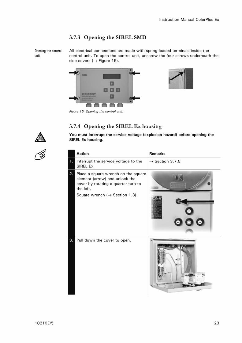
3.7.3 Opening the SIREL SMD
All electrical connections are made with spring-loaded terminals inside the
control unit. To open the control unit, unscrew the four screws underneath the
side covers ( Figure 15).
Figure 15: Opening the control unit.
3.7.4 Opening the SIREL Ex housing
You must interrupt the service voltage (explosion hazard) before opening the
SIREL Ex housing.
Action Remarks
1. Interrupt the service voltage to the
SIREL Ex.
Section 3.7.5
2. Place a square wrench on the square
element (arrow) and unlock the
cover by rotating a quarter turn to
the left.
Square wrench ( Section 1.3).
3. Pull down the cover to open.
Opening the control
unit

Instruction Manual ColorPlus Ex
24 10210E/5
3.7.5 Establish SIREL SMD/Ex electrical connections
For information about control signals, please refer to Section 2 in the
Reference Handbook.
The terminals of the SIREL Ex are located in the lower part of the housing
(Figure 16). The housing must be open in order to connect the electrical
connections Section 0.
The terminal assignment is identical for the SIREL SMD and SIREL Ex
( Figure 17).
Figure 16: Position of SIREL Ex terminals
Figure 17: Terminal block for SIREL SMD 85..264 VAC.

Instruction Manual ColorPlus Ex
10210E/5 25
Make up the electrical connections in the following order:
Terminals Used for Remarks
1. 20 Connection to photometer green
21 brown
22 white
23 yellow
2. 4 - 5 - 6 Relay output 1 The relay outputs are
freely configurable
( Reference Handbook). 7 - 8 - 9 Relay output 2
18 - 19 Reading output for
1st meas. angle
(90° reading in the case of
dual-angle instrument)
0/4 .. 20 mA, max.
burden 600
If unused, these
terminals must be
shorted with a jumper!
32 - 33 Reading output for
2nd meas. angle (25°
reading in the case of dual-
angle instrument)
3. 10 .. 17 Control signals for
1st meas. angle
Reference Handbook
26 .. 31 Control signals for
2nd meas. angle
Provided on dual-angle
instrument only.
16a Control signal for sensor
check
Reference Handbook
24 - 25 Connection to bus coupler Reference Handbook
4. 1 - 2 - 3 Mains voltage 85 .. 264 V; 47 .. 63 Hz
or 24 VDC; 25 W
Connection

Instruction Manual ColorPlus Ex
26 10210E/5
3.8 Initial start-up
Carry out the initial start-up according to the following table. In the event of
malfunctions, consult Section 6.
Action Remarks
1. Make sure the photometer and
control unit are correctly mounted
and connected.
Section 3
2. Switch on the power supply to the
control unit.
After a few seconds, a reading will
appear on the control unit display
(depends on the instrument type and
which unit is set).
3. Set the language of your region
( Section 4.4).
Now the menu text appear in the
desired language.
4. Set the measuring range you
require for your measurement
conditions ( Section 4.5).
5. Set the relay functions you require
for your measuring duty
( Section 4.7).
6. Secure your settings against
tampering with an access code
( Section 4.9).
If you don’t require an access code,
skip this step.
7. Carry out a 100% adjustment. Section 5.2

Instruction Manual ColorPlus Ex
10210E/5 27
4 Operation
4.1 Operating elements and display SIREL SMD
Pos. Name
1 Channel number
and reading
2 Measuring value
3 Unit set (e.g. E/m or
%T ( Reference
Handbook)
4 Arrow key up
5 Arrow key right
6 Arrow key down
7 Arrow key
left
8 Enter key
Figure 18: Operating elements and display.
The user guidance is the same as for SIREL. The only differences between
SIREL robust and SIREL are the integrated keypad/display and the enclosure.
Pos. Name
1 Integrated keypad
2 LC display
3 Connection
terminals
Figure 19: SIREL robust
SIREL
SIREL robust

Instruction Manual ColorPlus Ex
28 10210E/5
Figure 20: Operating elements of SIREL robust
Pos. Symbols Key functions
1, 2 / Switch between menu lines
Change numbers in the editing mode (see below)
4, 5 / Switch between the functions of a menu line
Change function values, shift a number’s decimal point
in the editing mode (see below)
4, 5 + Press both simultaneously to return to normal operation
3 Activate the editing mode (display shows > <)
Enter the setting (as confirmation)
SIREL Robust (cover
removed)
Key functions:

Instruction Manual ColorPlus Ex
10210E/5 29
4.1.1 Control components and display of the SIREL Ex
The operator prompting of the SIREL Ex is identical to that of the SIREL SMD.
Only the integrated keyboard and the housing differentiate the SIREL Ex from
the SIREL SMD.
Pos. Name
1 LC display
2 Square element for opening the
cover
3 Integrated
keyboard
Figure 21: SIREL Ex control components
Figure 22: SIREL Ex
Pos. Symbols Key functions
1, 2 / Switch between menu lines
Change the numerical values in editing mode ( below)
4, 5 / Switch between functions in a menu line
Change the function values and/or change the decimal
place of a numerical value in editing mode ( below)
4, 5 + Return to normal operation by pressing simultaneously
3 Activate editing mode (display of > <)
Apply the settings (confirmation)
Key functions,
SIREL Ex
Instruction Manual ColorPlus Ex
30 10210E/5
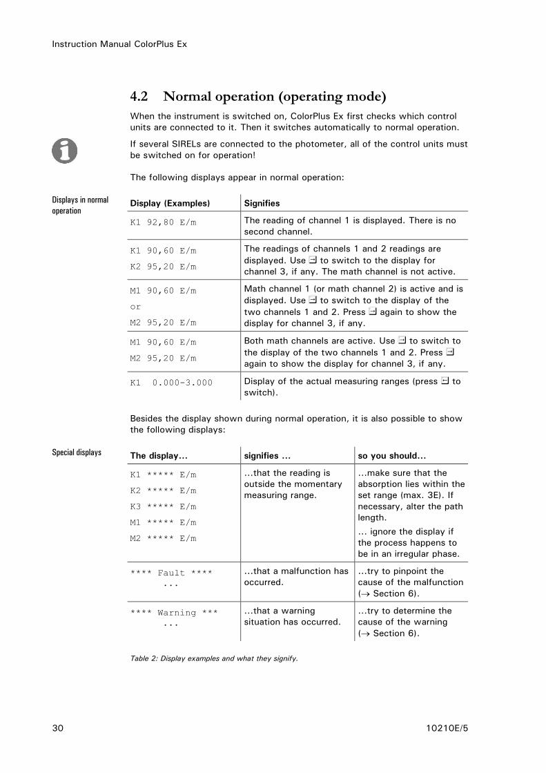
4.2 Normal operation (operating mode)
When the instrument is switched on, ColorPlus Ex first checks which control
units are connected to it. Then it switches automatically to normal operation.
If several SIRELs are connected to the photometer, all of the control units must
be switched on for operation!
The following displays appear in normal operation:
Display (Examples) Signifies
K1 92,80 E/m The reading of channel 1 is displayed. There is no
second channel.
K1 90,60 E/m
K2 95,20 E/m
The readings of channels 1 and 2 readings are
displayed. Use to switch to the display for
channel 3, if any. The math channel is not active.
M1 90,60 E/m
or
M2 95,20 E/m
Math channel 1 (or math channel 2) is active and is
displayed. Use to switch to the display of the
two channels 1 and 2. Press again to show the
display for channel 3, if any.
M1 90,60 E/m
M2 95,20 E/m
Both math channels are active. Use to switch to
the display of the two channels 1 and 2. Press
again to show the display for channel 3, if any.
K1 0.000-3.000 Display of the actual measuring ranges (press to
switch).
Besides the display shown during normal operation, it is also possible to show
the following displays:
The display... signifies ... so you should...
K1 ***** E/m
K2 ***** E/m
K3 ***** E/m
M1 ***** E/m
M2 ***** E/m
...that the reading is
outside the momentary
measuring range.
...make sure that the
absorption lies within the
set range (max. 3E). If
necessary, alter the path
length.
... ignore the display if
the process happens to
be in an irregular phase.
**** Fault ****
...
...that a malfunction has
occurred.
...try to pinpoint the
cause of the malfunction
( Section 6).
**** Warning ***
...
...that a warning
situation has occurred.
...try to determine the
cause of the warning
( Section 6).
Table 2: Display examples and what they signify.
Displays in normal
operation
Special displays

Instruction Manual ColorPlus Ex
10210E/5 31
4.3 Service mode
The photometer can be configured in the service mode. Measuring is
interrupted. The following menu control appears on the display:
Action Display (example) Remarks
1. Access code
> 000000 <
If no personal access
code has been set,
confirm with . Then
continue with step 3.
2. Enter code:
/ Change number
/ Change place
Access code
> ...... < Now enter your own
access code, or the
factory default
000000.
3. * 100% ADJUST. *
* *
Instrument is in the
service mode.
Depending on the configuration, the reading output either switches to 0/4 mA
or remains frozen at the last reading ( Reference Handbook).
4.4 Set your language
The control unit’s display can be set to English, German, French or Italian.
Action Display (example) Remarks
1. Switch to service
mode.
* 100% ABGL. *
* * Section 4.3
2. 3 x to * KONFIGURIEREN*
* *
3. > Sprache <
Deutsch
4. Activate editing mode
with .
Sprache
> Deutsch <
5. Select language:
/
Sprache
> ... <
6. Confirm selection with
.
> Language <
...
7. + (together) K1 68.2 %T
K2 85.8 %T
Instrument in normal
operation.
Applies in service
mode:
Instruction Manual ColorPlus Ex
32 10210E/5
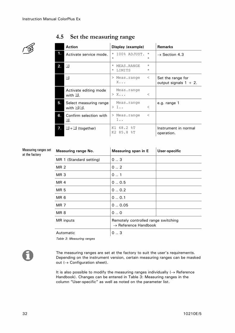
4.5 Set the measuring range
Action Display (example) Remarks
1. Activate service mode. * 100% ADJUST. *
* * Section 4.3
2. * MEAS.RANGE *
* LIMITS *
3
. > Meas.range <
X... Set the range for
output signals 1 + 2.
4
. Activate editing mode
with .
Meas.range
> X... <
5. Select measuring range
with /.
Meas.range
> 1.. <
e.g. range 1
6. Confirm selection with
.
> Meas.range <
1..
7. + (together) K1 68.2 %T
K2 85.8 %T
Instrument in normal
operation.
Measuring range No. Measuring span in E User-specific
MR 1 (Standard setting) 0 .. 3
MR 2 0 .. 2
MR 3 0 .. 1
MR 4 0 .. 0.5
MR 5 0 .. 0.2
MR 6 0 .. 0.1
MR 7 0 .. 0.05
MR 8 0 .. 0
MR inputs Remotely controlled range switching
Reference Handbook
Automatic 0 .. 3
Table 3: Measuring ranges
The measuring ranges are set at the factory to suit the user’s requirements.
Depending on the instrument version, certain measuring ranges can be masked
out ( Configuration sheet).
It is also possible to modify the measuring ranges individually ( Reference
Handbook). Changes can be entered in Table 3: Measuring ranges in the
column “User-specific” as well as noted on the parameter list.
Measuring ranges set
at the factory

Instruction Manual ColorPlus Ex
10210E/5 33
4.6 Configure the channels
Depending on the instrument type, the instrument can have 1..3 channels
(wavelengths) and two calculation channels (math channels).
All of the channels are configured at the factory to suit the user’s needs. No
setting is required upon installation.
4.7 Set the relay functions
All control units have two freely configurable relay outputs.
Several functions can be assigned to a given relay. The relay in question will
be activated whenever one of the configured functions becomes active (OR
link).
Action Display (example) Remarks
1. Activate service mode. * 100% ADJUST. *
* *
Section 4.3
2. 3 x * CONFIGURATION*
* *
3. Configure relay 1
8 x .
> Relay 1 <
li al se wa in
4. Activate editing mode
with .
Relay 1
>li al se wa in<
5. Assign functions:
/ Function
on/off
/ Change
function
Relay 1
>LI al se wa in<
li = Limit 1
exceeded
al = Alarm (fault
has occurred)
se = Instrument in
service mode
wa = Warning
(warning
situation has
occurred)
in = Relay inverted
Functions in CAPITAL
LETTERS are activated
(e.g. LI).
6. Confirm selection with
.
> Relay 1 <
LI al se wa in
7. Configure relay 2 with
.
> Relay 2 <
li AL se WA in
8. Activate editing mode
with .
Relay 2
>li AL se WA in<

Instruction Manual ColorPlus Ex
34 10210E/5
Action Display (example) Remarks
9. Assign functions:
/ Function
on/off
/ Change func-
tion
Relay 2
>li AL se wa in< li = Limit 2
exceeded
al = Alarm (fault
has occurred)
se = Instrument in
service mode
wa = Warning
(warning
situation has
occurred)
in = Relay inverted
Functions in CAPITAL
LETTERS are activated
(e.g. AL).
10. Confirm selection with
.
> Relay 2 <
li AL se wa in
11. + (together) K1 68.2 E/m
K2 85.8 %T Instrument in normal
operation.
After the relays have been configured, it is necessary to set the limits
( Section 4.8).
4.8 Set the limits
Up to two limits can be
programmed, each with an upper
and a lower threshold value
( Figure 23: Upper and lower
thresholds of a limit.).
If the reading reaches the upper
threshold, the limit becomes active
and remains activated until the
reading drops back below the lower
threshold.
Figure 23: Upper and lower thresholds of a
limit.
The limits are available only if the relay has been so configured
( Section 4.7).

Instruction Manual ColorPlus Ex
10210E/5 35
Action Display (example) Remarks
1. Switch to the service
mode.
* 100% ADJUST. *
* * Section 4.3
2. * MEAS.RANGE *
* LIMITS *
3. > LI1 source <
Channel 1
LI1 = Limit 1
LI2 = Limit 2
4. Activate editing mode
with .
LI1 source
> Channel 1 <
5. Select source:
/
LI1 source
> ... <
Channel to which the
limit should apply
(channel 1 .. 3 or math
channel 1 or 2)
6. Confirm selection with
.
> LI1 source <
...
7. > Upper limit1 <
1.000 E/m
8. Activate editing mode
.
Upper limit1
> 1.000 E/m <
9. Set upper threshold
value:
/ Change number
/ Change place
Upper limit1
> ... <
Set the value at which
the limit should be
activated.
10. Confirm setting with
.
> Upper limit1 <
...
11. > Lower limit1 <
0.800 E/m
12. Activate editing mode
with .
Lower limit1
> 0.800 E/m <
13. Set lower threshold
value:
/ Change number
/ Change place
Lower limit1
> ... < Now set the value at
which the limit should
be deactivated again.
14. Confirm setting with
.
> Lower limit1 <
...
15. > LI2 source <
Channel 2 Repeat procedure for
limit 2 steps 6 to 16.
16. + (together) K1 68.2 E/m
K2 85.8 %T
Instrument in normal
operation.

Instruction Manual ColorPlus Ex
36 10210E/5
4.9 Set the access code
You can use a self-defined access code to protect the ColorPlus Ex settings
against tampering.
Action Display (example) Remarks
1. Activate service mode. * 100% ADJUST. *
* * Section 4.3
2. 3 x * CONFIGURATION*
* *
3. 2 x > Access code <
000000
4. Activate editing mode
with .
Access code
> 000000 <
5. Enter new code:
/ Change number
/ Change place
Access code
> ...... <
Note the code in the
field below so you
don’t forget it!
6. Confirm selection with
.
> Access code <
......
7. + (together) K1 68.2 E/m
K2 85.8 %T Instrument in normal
operation.
New access code:
A forgotten access code can be deleted only by a SIGRIST service technician!

Instruction Manual ColorPlus Ex
10210E/5 37
5 Servicing
Do not open the photometer before the power supply to the control unit has
been disconnected and then a waiting time of ten minutes has passed to allow
the light source to cool down sufficiently (EXPLOSION HAZARD)!
The electric power supplied to the UV light source CAN CAUSE FATAL
INJURY. So it is absolutely necessary to disconnect the power supply to
any instrument with a UV light source before opening the instrument!
The UV radiation from the bulb can damage your eyes!
The UV light source and the light source housing can reach temperatures
above 80°C!
This section describes the activities that have to be performed either
preventively or as required in order to ensure proper operation of the
photometer.
Activities that are not mentioned in this Instruction Manual may be carried out
only by personnel specifically trained to perform them!
5.1 Service schedule
When Who What Purpose
Every 3 months
or more
frequently (as
needed)
User 100% adjustment of the
photometer ( Section 5.2)
Necessary in order to
maintain measuring
accuracy. Interval depends
on measuring environment.
Once a year or
as needed
User Functional check with
reference glass ( Section
5.3)
Absolutely necessary for
maintaining measuring
accuracy.
Once a year or
as needed
User Replacement of desiccant in
sensor head (transmitter
and receiver) ( Section
5.4)
Absolutely necessary in
order to maintain measuring
accuracy.
In the event of
“Sealing“
warning
User Replacement of desiccant in
transmitter / receiver
( Sections 5.5 and 5.6)
Absolutely necessary in
order to maintain measuring
accuracy.
As needed User Cleaning or replacement of
flow cell windows
( Sections 5.7 and 5.8)
Absolutely necessary in
order to maintain measuring
accuracy.
In the event of
“UV- lamp“ fault
User Replace UV light source
( Section 5.9)
Correction of malfunction.
As needed Service
office
Cleaning of optics In the event of
unsatisfactory measuring
results.
Table 4: Service schedule
Recommended
service work
Instruction Manual ColorPlus Ex
38 10210E/5
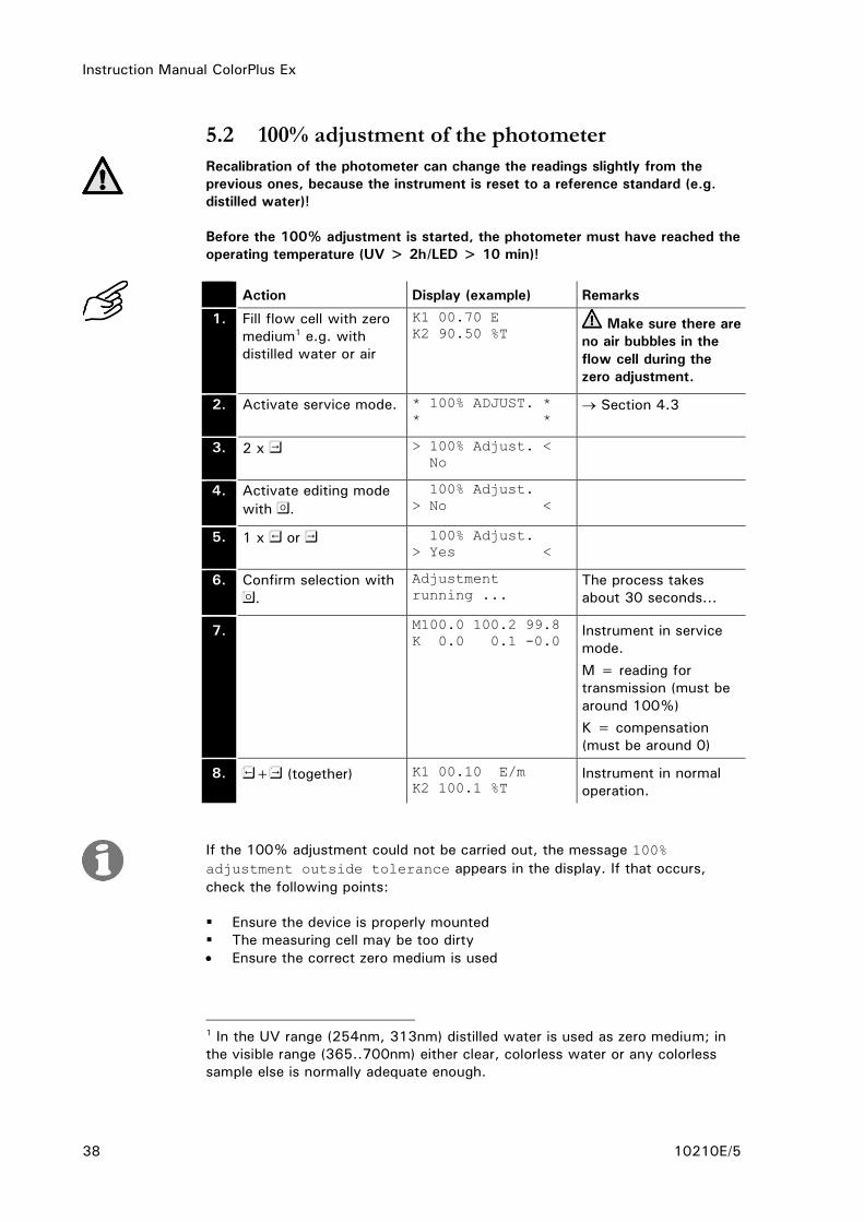
5.2 100% adjustment of the photometer
Recalibration of the photometer can change the readings slightly from the
previous ones, because the instrument is reset to a reference standard (e.g.
distilled water)!
Before the 100% adjustment is started, the photometer must have reached the
operating temperature (UV > 2h/LED > 10 min)!
Action Display (example) Remarks
1. Fill flow cell with zero
medium1 e.g. with
distilled water or air
K1 00.70 E
K2 90.50 %T Make sure there are
no air bubbles in the
flow cell during the
zero adjustment.
2. Activate service mode. * 100% ADJUST. *
* * Section 4.3
3. 2 x > 100% Adjust. <
No
4. Activate editing mode
with .
100% Adjust.
> No <
5. 1 x or 100% Adjust.
> Yes <
6. Confirm selection with
.
Adjustment
running ... The process takes
about 30 seconds...
7. M100.0 100.2 99.8
K 0.0 0.1 -0.0 Instrument in service
mode.
M = reading for
transmission (must be
around 100%)
K = compensation
(must be around 0)
8. + (together) K1 00.10 E/m
K2 100.1 %T Instrument in normal
operation.
If the 100% adjustment could not be carried out, the message 100%
adjustment outside tolerance appears in the display. If that occurs,
check the following points:
Ensure the device is properly mounted
The measuring cell may be too dirty
Ensure the correct zero medium is used
1 In the UV range (254nm, 313nm) distilled water is used as zero medium; in
the visible range (365..700nm) either clear, colorless water or any colorless
sample else is normally adequate enough.

Instruction Manual ColorPlus Ex
10210E/5 39
5.3 Functional check with reference glass
Action Remarks
1. Fill the flow cell with zero medium.
Do not empty the flow cell again until you
have taken the reading (point 10)!
2. Do not open the photometer before the
power supply to the control unit has been
disconnected and then a waiting time of ten
minutes has passed to allow the light source
to cool down sufficiently (EXPLOSION
HAZARD)!
Disconnect the power supply of the
photometer to the control unit.
3. Loosen the Allen screw (arrow) at the
receiver enclosure by about ½ turn and pull
off the locking piece.
4. Loosen nut (A) enough to be able to swing
the hinged ring away easily. Take off the
entire clamping ring and then remove the
receiver enclosure.
5. Loosen knurled nut (A) and rotate the
checking glass into the checking position
(arrow). Fix the checking glass in place with
knurled nut (A) and replace and fasten the
enclosure cover.
The checking glass must be in contact
with stop (B)!
Make a note of the reading stated inside the
enclosure.
6. Replace the receiver enclosure and fasten it
with the clamping ring.
7. Restart the photometer and wait until it has
reached its operating temperature (UV
2h/LED 10 min).
8. Set the menu *100% Adjust.* on the control
unit (Section 5.2).
Instruction Manual ColorPlus Ex
40 10210E/5
Action Remarks
9. Press key .
Depending on the configuration, between one
and three transmission values will appear in
the top line.
10. Take the reading(s) and note it down.
11. Compare the measured value with the value
noted down from inside the enclosure.
If the variance is more than ±0.1 %T, repeat
steps 1 − 11. If the measured value varies
too much again, contact your service office.
If the measured value agrees with the value
stated inside the enclosure, proceed with
step 12.
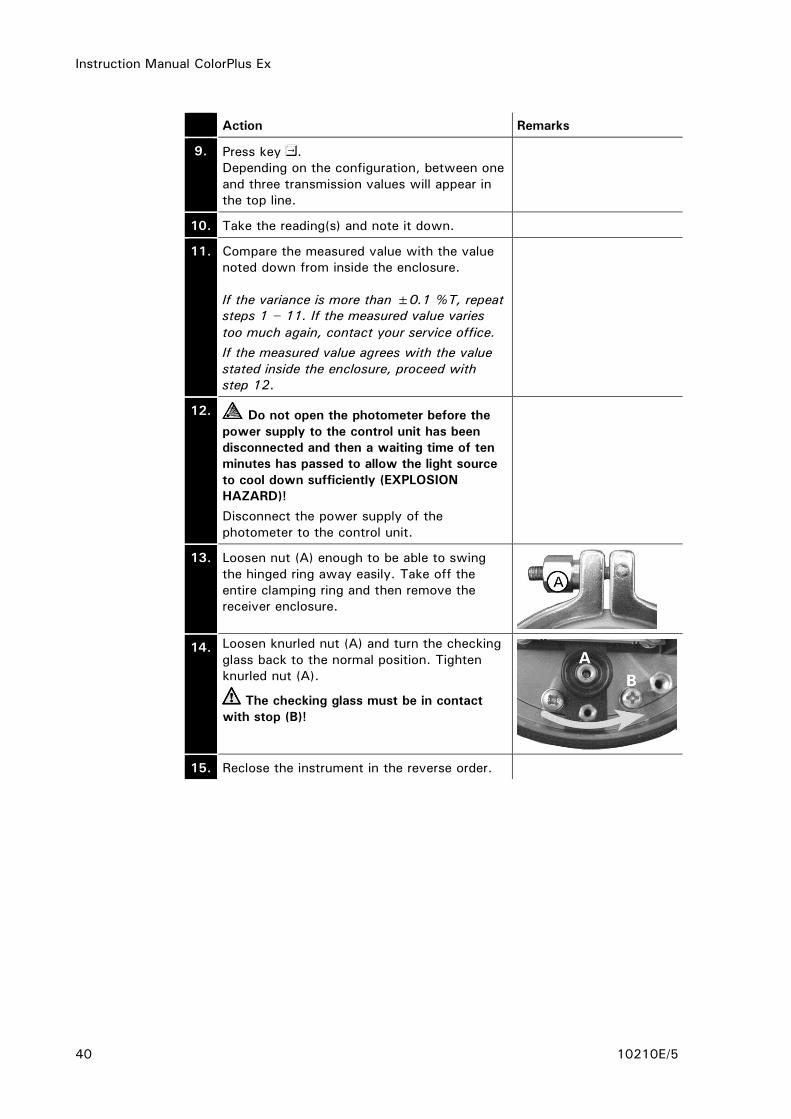
12. Do not open the photometer before the
power supply to the control unit has been
disconnected and then a waiting time of ten
minutes has passed to allow the light source
to cool down sufficiently (EXPLOSION
HAZARD)!
Disconnect the power supply of the
photometer to the control unit.
13. Loosen nut (A) enough to be able to swing
the hinged ring away easily. Take off the
entire clamping ring and then remove the
receiver enclosure.
14. Loosen knurled nut (A) and turn the checking
glass back to the normal position. Tighten
knurled nut (A).
The checking glass must be in contact
with stop (B)!
15. Reclose the instrument in the reverse order.

Instruction Manual ColorPlus Ex
10210E/5 41
5.4 Replacement of the desiccant in the sensor head
Action Remarks
1. Do not open the photometer before the
power supply to the control unit has been
disconnected and then a waiting time of ten
minutes has passed to allow the light source
to cool down sufficiently (EXPLOSION
HAZARD)!
(Cooling down of instrument to a safe
temperature level and fading of the residual
charges.)
Disconnect the power supply of the
photometer to the control unit.
2. Remove the six screws (A) around the
periphery of the sensor head.
3. Withdraw the sensor head from the adapter
ring.
4. Loosen the three screws (A) and remove the
leakage protector.
5. Remove the old desiccant.
Place the new desiccant (A) in the leakage
protector and then cover it with the dust
protector (B).

Instruction Manual ColorPlus Ex
42 10210E/5
Action Remarks
6. Replace the seals (arrows) on the leakage
protector (seals are supplied together with
new desiccant).
7. Clean window (A) with a cotton rag.
8. Reassemble the instrument in reverse order
and restart it.
If you have to replace the desiccant frequently, you should have a SIGRIST
service technician check the tightness of the Ex enclosure.

Instruction Manual ColorPlus Ex
10210E/5 43
5.5 Replacement of the desiccant in the transmitter
The electric power supplied to the UV light source CAN CAUSE FATAL
INJURY! So for all instruments with a UV light source, it is absolutely
necessary to disconnect the power supply before opening the enclosure!
The UV radiation from the bulb can damage your eyes!
The UV light source and the light source housing can reach temperatures
above 80°C!
Action Remarks
1. Do not open the photometer before
the power supply to the control unit has
been disconnected and then a waiting
time of ten minutes has passed to allow
the light source to cool down sufficiently
(EXPLOSION HAZARD)! (Cooling down of
instrument to a safe temperature level and
fading of the residual charges)
Disconnect the power supply of the
photometer to the control unit.
2. Loosen the Allen screw (arrow) at the
transmitter enclosure by about ½ turn and
pull off the locking piece.
3. Loosen nut (A) enough to be able to
swing the hinged ring away easily. Take
off the entire clamping ring and then
remove the transmitter enclosure.
4. Remove the saturated desiccant bag (A).
Take the new desiccant bag, shake its
contents to one end and roll the bag up.
In this form it can be inserted easily into
the transmitter.
5. Check the enclosure seal (B) and replace it
if necessary.
6. Reassemble the photometer in reverse
order and restart it.

Instruction Manual ColorPlus Ex
44 10210E/5
5.6 Replacement of the desiccant in the receiver
Action Remarks
1. Do not open the photometer before the
power supply to the control unit has been
disconnected and then a waiting time of ten
minutes has passed to allow the light source
to cool down sufficiently (EXPLOSION
HAZARD)! (Cooling down of instrument to a
safe temperature level and fading of the
residual charges)
Disconnect the power supply of the
photometer to the control unit.
2. Loosen the Allen screw (arrow) at the
receiver enclosure by about ½ turn and pull
off the locking piece.
3. Loosen nut (A) enough to be able to swing
the hinged ring away easily. Take off the
entire clamping ring and then remove the
receiver enclosure.
4. Remove the saturated desiccant bag (A).
Take the new desiccant bag, shake its
contents to one end and roll the bag up. In
this form it can be inserted easily into the
receiver.
5. Check the enclosure seal (B) and replace it if
necessary.
6. Reassemble the photometer in reverse order
and restart it.

Instruction Manual ColorPlus Ex
10210E/5 45
5.7 Cleaning/replacement of the flow cell windows in bypass flow cells
Action Remarks
1. Do not open the photometer before the
power supply to the control unit has been
disconnected and then a waiting time of ten
minutes has passed to allow the light source
to cool down sufficiently (EXPLOSION
HAZARD)! (Cooling down of instrument to a
safe temperature level and fading of the
residual charges)
Disconnect the power supply of the
photometer.
2. Interrupt the sample flow through the flow
cell and let it run empty. Now remove the
sample inlet and the sample outlet.
3. Remove the photometer from the measuring
setup and place it aside on a firm surface.
4. Take off the transmitter/receiver by removing
the six screws (A).
Get a firm grip on the transmitter/receiver
while doing this!
5. Remove the four screws from the adapter
plate (B) and take the plate out of the
measuring setup.
6. Loosen the fitting on the flow cell with the
special wrench (SW32).

Instruction Manual ColorPlus Ex
46 10210E/5
Action Remarks
7. Now you can remove the threaded ring,
thrust ring, seal and flow cell window.
8. Clean the flow cell window with a suitable
cleaning agent. Take care not to dirty it again
during reinstallation. If necessary, replace the
flow cell window and seal.
9. If necessary, replace the leakage protector
seal (A). Remove the old seal and place the
new seal into the groove on the leakage
protector.
If necessary, replace the desiccant and
the seal ( Section 5.6).
10. Reassemble the photometer in reverse order
and restart it.
11. Carry out a 100% adjustment as directed in
Section 5.2.
5.8 Cleaning/replacement of the flow cell windows on the Varivent® flow cell
Action Remarks
1. Interrupt the sample flow through the in-line
flow cell and let it run empty. Switch off the
photometer’s power supply.
2. Remove first nut (A) and then the hinged
rings on the transmitter and receiver sides.
Get a firm grip on the transmitter /
receiver while doing this!
Instruction Manual ColorPlus Ex
10210E/5 47
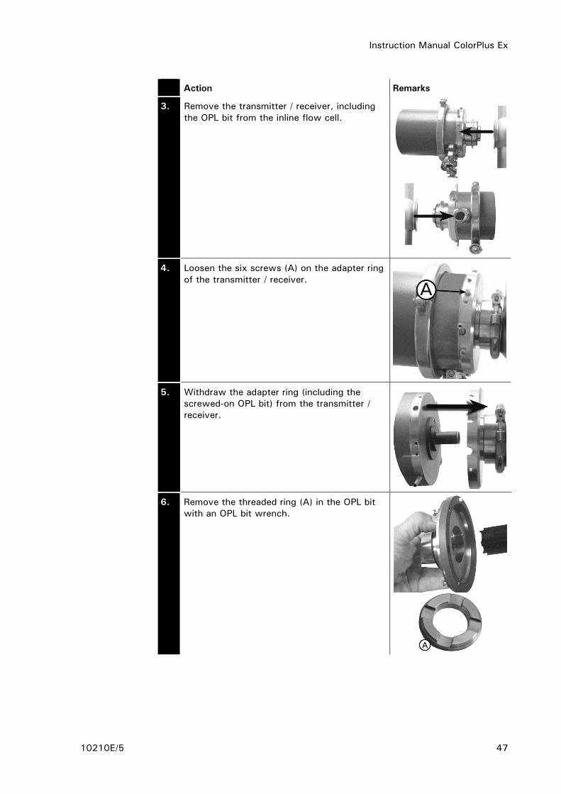
Action Remarks
3. Remove the transmitter / receiver, including
the OPL bit from the inline flow cell.
4. Loosen the six screws (A) on the adapter ring
of the transmitter / receiver.
5. Withdraw the adapter ring (including the
screwed-on OPL bit) from the transmitter /
receiver.
6. Remove the threaded ring (A) in the OPL bit
with an OPL bit wrench.

Instruction Manual ColorPlus Ex
48 10210E/5
Action Remarks
7. Take the thrust ring and the flow cell window
with seal out of the OPL bit. Remove the seal
from the flow cell window and clean the
window with a cleaning paper or rag, possibly
using warm soapy water. Take care not to
dirty the window again during reinstallation. If
necessary, replace the window.
8. If necessary, replace the seal (B). Place the
seal into the window’s groove. Insert the
window into the OPL bit with the seal facing
downward.
9. Place the thrust ring into the OPL bit with the
ring’s groove facing downward.
10. Screw in the threaded ring and tighten it with
the OPL bit wrench.
11. If necessary, place a new seal (arrow) into
the groove on the OPL bit.
12. If necessary, replace the leakage protector
seal (A). Remove the old seal and place the
new seal into the groove on the leakage
protector.
If necessary, replace the desiccant and
the seal ( Section 5.4).
13. Slip the adapter ring (with the screwed-on
OPL bit) on the transmitter / receiver and
fasten it with the six screws.

Instruction Manual ColorPlus Ex
10210E/5 49
Action Remarks
14. Clean all contact surfaces on the inline
housing.
15. Insert the transmitter / receiver with screwed-
on adapter ring and OPL bit back into the
inline housing.
Make sure the groove (A) of the
transmitter / receiver is pointing upward after
reassembly!
16. Refasten the transmitter / receiver to the
inline housing with the hinged ring and secure
it with nut A.
17. Carry out a 100% adjustment as directed in
Section 5.2.
18. Restart the sample flow and switch the
power supply back on.
Instruction Manual ColorPlus Ex
50 10210E/5
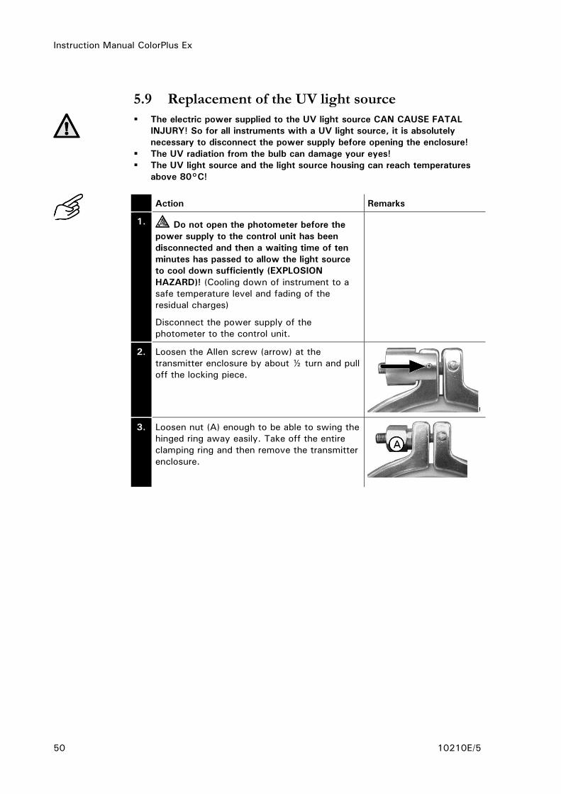
5.9 Replacement of the UV light source
The electric power supplied to the UV light source CAN CAUSE FATAL
INJURY! So for all instruments with a UV light source, it is absolutely
necessary to disconnect the power supply before opening the enclosure!
The UV radiation from the bulb can damage your eyes!
The UV light source and the light source housing can reach temperatures
above 80°C!
Action Remarks
1. Do not open the photometer before the
power supply to the control unit has been
disconnected and then a waiting time of ten
minutes has passed to allow the light source
to cool down sufficiently (EXPLOSION
HAZARD)! (Cooling down of instrument to a
safe temperature level and fading of the
residual charges)
Disconnect the power supply of the
photometer to the control unit.
2. Loosen the Allen screw (arrow) at the
transmitter enclosure by about ½ turn and pull
off the locking piece.
3. Loosen nut (A) enough to be able to swing the
hinged ring away easily. Take off the entire
clamping ring and then remove the transmitter
enclosure.

Instruction Manual ColorPlus Ex
10210E/5 51
Action Remarks
4. Pull the UV light source’s plug (A) out of the
circuit board.
5. Loosen the fastening screw (B) of the UV light
source.
6. Don’t touch the glass of the UV bulb with
your fingers! Clean it with alcohol before
installation!
Withdraw the UV bulb (C) from its base.
7. Insert the new UV bulb (C) into the socket all
the way to the stop (the mark on the bulb
must line up with that on the socket) and
tighten the fastening screw (B). Reinsert the
plug (A) into the circuit board.
8. Reassemble the photometer in the reverse
order and restart it.
9. Carry out a 100% adjustment as directed in
Section 5.2.

Instruction Manual ColorPlus Ex
52 10210E/5
6 Troubleshooting
6.1 Pinpointing the cause of a malfunction
To narrow down the cause of a malfunction, proceed step by step according
to the following table. If the action taken fails to produce the desired result,
consult Customer Service ( Section 6.5).
Perceived fault Action
No display Make sure the control unit is properly
connected to the supply voltage
( Section 3.7)
Check the fuses in the control unit
( Reference Handbook)
Fault message or warning
in the display
Analyze the fault message / warning
( Sections 6.2 and 6.3)
The reading seems
suspect
Check whether the photometer is correctly
mounted ( Section 3.1)
Make sure the servicing chores have been
carried out properly in accordance with the
Service Schedule ( Section 5.1).
Carry out a 100% adjustment on the
photometer ( Section 5.2)
Replace the desiccant in the sensor head
( Section 5.4).
Carry out a functional check with the checking
glass ( Section 5.3).
No measured value output
signal (0 mA)
- This status signals that a fault has occurred in
the photometer.
- Analyze the fault displayed fault message
( Section 6.2).
Table 5: Pinpointing a malfunction
6.2 Fault messages
In the ColorPlus Ex, readings are measured, inputs monitored and outputs
updated continuously. If the ColorPlus Ex detects a fault during this process, a
fault message will be emitted and displayed on the control unit.

Instruction Manual ColorPlus Ex
10210E/5 53
The ColorPlus Ex can detect the following faults:
Message Signifies Possible causes
connection
lost ... The control unit has no
connection to the photometer.
Connection to
photometer interrupted
Defective electronics
( Service technician)
Fault
UV-lamp The detectors are not receiving
any light.
Defective UV light
source ( Section 5.9)
Defective electronics
( Service technician)
Fault
LED The detectors are not receiving
any light from the LED.
Defective LEDs
( Service technician)
Fault
Measurement The AD converter is overloaded. The detectors are
receiving too much light
Enclosure not tight
Defective electronics
( Service technician)
Fault-
Current 1 Incorrect reading being
measured at reading output 1.
Open connection
terminal at reading
output ( Section 3.7)
Interruption in control
loop of reading output
Loose contract at
reading output
Fault-
Current 2 Incorrect reading being
measured at reading output 2.
Open connection
terminal at reading
output ( Section 3.7)
Interruption in control
loop of reading output
Loose contact at
reading output
Fault
AnalogIn 1 Analog signal 1 has fallen below
a preset threshold
Signal below the
configurable fault
threshold
Fault
AnalogIn 2 Analog signal 2 has fallen below
a preset threshold
Signal below the
configurable fault
threshold
System fault At the program start, at least 5
system errors were entered in
the history within two minutes
(Reference Handbook)
The parameter memory
has lost its data (
Service technician)
The error history is
overfilled ( Service
technician)
Table 6: Fault messages

Instruction Manual ColorPlus Ex
54 10210E/5
6.3 Warnings
Temperature, leakage and degree of contamination are monitored continuously
in the ColorPlus Ex. If this monitoring shows that a limit has been exceeded, a
warning is emitted and displayed on the control unit.
These warnings can be detected by ColorPlus Ex:
Message Signifies Possible causes
Warning
Temperature The temperature in the
transmitter has exceeded
65°C
Excessively high medium
or ambient temperature
and a defective cooling
system or none at all.
Warning
Sealing The relative humidity in
the transmitter (and
possibly also in the
receiver) has risen above
the preset limit
The desiccant is
saturated ( Sections
5.5 and 5.6)
Seals are no longer
sealing properly
Warning
Soiling Contamination of the
flow cell has exceeded
the preset limit (only
present in the version for
water).
Badly contaminated
medium
Cleaning interval too
long
Incorrect installation
position ( Section 3)
Warning
Neg.Ext. The measuring value has
exceeded the negative
limit (Neg.Ext. LI)
The device is dirty
( Section 5.7, 5.8)
Table 7: Warnings

Instruction Manual ColorPlus Ex
10210E/5 55
6.4 Information
The ColorPlus Ex provides information messages in the case of automatically
executed configuration changes:
Message Signifies Causes
Caution!!
MR changed One or more measuring
ranges has been
automatically adapted
One or more measuring
ranges has been adapted
because it lies outside
the maximum
permissible extinction of
3E ( Reference
Handbook)
Caution!!
Tab. changed
The table has been
automatically adapted
The automatic
adaptation of the
measuring range
prompted a table
adaptation ( Reference
Handbook)
Caution!!
Scal. changed
The scaling was adapted
automatically
The automatic
adaptation of the
measuring range
prompted a scaling
adaptation ( Reference
Handbook)
6.5 Customer service information
Whenever you have questions about SIGRIST products, please start by reading
the documentation supplied with the equipment. Also check the Errata
accompanying the documentation. These contain information that became
available subsequently.
If you do not find the answer, please contact the Service Office responsible for
your country or your region. If you don’t know where to find it, Customer
Service of SIGRIST-PHOTOMETER AG in Switzerland will gladly give you the
relevant contact address.
You will also find the current list of all SIGRIST country representatives in the
internet at www.photometer.com.
When you contact a SIGRIST Service Office or Customer Service, please make
sure you have the following information at hand:
The serial number of the control unit ( Section 1.5).
A description of the instrument behavior and the worksteps being
performed as the problem arose.
A description of how you proceeded when trying to solve the problem
yourself.
Documentation on any non-SIGRIST product operated together with the
photometer or its peripheral devices.

Instruction Manual ColorPlus Ex
56 10210E/5
If you have problems with the reading, please have the following additional
information at hand. It can be found in the menus for the sections Info,
Adjustment, Compensation and Calibration:
Name Option Value
System information Section 1
Instr. No. No.
Software Version No.
Error History F01
F02
F03
F04
F05
F06
F07
F08
F09
F10
Adjustment values Adjust.value 1a
Adjust.value 2a
Adjust.value 3a
Adjust.value 1b
Adjust.value 2b
Adjust.value 3b
Calibration values Calibr. value 1a
Calibr. value 2a
Calibr. value 3a
Calibr. value 1b
Calibr. value 2b
Calibr. value 3b
Contamination
compensation
Channel 1
Channel 2
Channel 3
Compensation Analog
input 1 / 2
Zero scal.
100%-Scal.
Ref.value
Table 8: Customer service information

Instruction Manual ColorPlus Ex
10210E/5 57
7 Taking Out of Service/storage
Do not open the photometer before the power supply to the control unit has
been disconnected and then a waiting time of ten minutes has passed to allow
the light source to cool down sufficiently (EXPLOSION HAZARD)! (Cooling
down of the device to a safe temperature level and elimination of residual
charges.)
Action
1. Switch off the power supply to the control unit and disconnect all of
the electrical connections to the control unit.
2. Dismount the control unit.
3. Thoroughly clean all surfaces that have come into contact with the
medium. Now no toxic, corrosive or loose deposits should remain
inside.
4. Make sure that all covers and hoods are closed and all closures on the
photometer and control unit are secured.
No special conditions are required for storage of the equipment, but be sure to
observe the following:
The photometer and control unit contain electronic components. The
storage must satisfy the normal conditions required for such components.
In particular, the storage temperature should remain within the –20 ..
50°C range.
During storage, the photometer, control unit and accessories must be
protected against weathering, condensing moisture and aggressive gases.
Taking out of service
Storage of the
equipment

Instruction Manual ColorPlus Ex
58 10210E/5
8 Packing/Transport
Whenever possible, use the original packing materials when packing the
photometer and its peripherals for shipment. If the materials are no longer
available, observe these instructions:
Prior to packing, close all openings with pressure-sensitive tape or plugs to
prevent any packing materials from penetrating them.
The photometer contains optical and electronic components. Pack the
instrument in such a way that it is protected against impact and blows
during shipment.
Pack all of the peripheral devices and accessories separately, and mark
each part with the serial number ( Section 1.5). This will prevent mixups
later on and facilitate identification of the parts.
Packed this way, the photometer and control unit can be shipped by any
normal mode of transport and in any position.

Instruction Manual ColorPlus Ex
10210E/5 59
9 Disposal
This product falls in Category 9 "Monitoring and Control Instruments" of
European Directive RL 2002/95/EC (RoHS).
Disposal of the photometer and its peripheral devices must be carried out in
accordance with the regional legal provisions!
Neither the photometer nor the control unit contains any sources of pollutant
radiation. Dispose of or reuse the materials in question in accordance with the
following table:
Category Materials Disposal possibilities
Packing Cardboard, wood, paper Reuse as packing material, local
waste disposal points,
incinerators.
Protective films, polystyrene
shells
Reuse as packing material,
recycle.
Electronics Printed circuit boards,
electromechanical
components
Disposal as electronics scrap.
Optics Glass, aluminum, brass Recycle via used glass and scrap
metal collection points.
UV bulb Contains mercury!
Metal, glass, porcelain
As special waste via the local
disposal point.
Enclosure Stainless steel / aluminum Scrap metal collection points.
Flow cells Stainless steel Scrap metal collection points.
PVDF As special waste via the local
disposal point.
Desiccant Ordinary waste disposal
(chemically harmless)
Table 9: Materials and their disposal

Instruction Manual ColorPlus Ex
60 10210E/5
10 Spare Parts
The parts mentioned in this documentation and their Article Numbers are listed
in the following table:
Art. No. Article name
114679 ColorPlus UV-Light source
112860 Housing seal sender/receiver ColoPlusEx O-Ring EPDM 117,10x3,53,
75 Shore
111391 Desiccant bag, 30g
115555 Desiccant ring to sensor head for ColorPlus Ex wit h two seals
106069 Tempax glass window for KPA0.5 44/35.5x4.75/2.25, Pos. 6a
106076 Suprasil window for KPA0.5 44/35.5x4.75/2.25
106072 Tempax glass window for KPA2 44/35.5x5.5/1.5, Pos. 6a
106079 Bypass flow cell window, UV version, path 2mm
107633 Measuring cell window for KPA & ColorPlus 44 x 3.5 Pos. 6, Tempax
107717 Measuring cell window for KPA & ColorPlus 44 x 3.5, Pos. 6, Suprasil
114901 OPL-Bit window borosilicate ColorPlus Inline
114902 OPL-Bit window quartz ColorPlus Inline
114903 OPL-Bit window sapphire ColorPlus Inline
113296 Leakage protector seal, ColorPlus in-line (VITON O-Ring 11.91x2.62)
114947 1 set EPDM seals for OPL-Bit, for ColorPlus
114948 1 set NBR seals for OPL-Bit, for ColorPlus
114949 1 set FPM seals for OPL-Bit, for ColorPlus
114950 1 set FFPM seals for OPL-Bit, for ColorPlus
114098 O-Ring FEP/FKM 37.69x3.53 ColorPlus Measuring cell SS
115556 Cooling for ColorPlus Ex
116268 Control unit SIREL SMD 85..264 VAC
116547 SIREL SMD 24V
118583 Control unit SIREL SMD EX 85..264 VAC
108157 SIREL: cover with membrane keypad
Table 10: Spare parts and Article Numbers
Instruction Manual ColorPlus Ex
10210E/5 61
11 Appendix

Instruction Manual ColorPlus Ex
62 10210E/5
Instruction Manual ColorPlus Ex
10210E/5 63
12 Index
1 100% adjustment .................... 38
A access code, setting ................. 36
accessories ............................... 6
adjustment, 100% ................... 38
Article Numbers ....................... 60
B bus coupler ............................. 29
C CE ........................................... 7
conformity ................................ 7
connections, electrical .............. 23
control unit, opening ................ 23
Customer Service..................... 55
D danger .................................... 13
desiccant, sensor head ............. 41
desiccant, transmitter ............... 43
design purpose .......................... 7
directives .................................. 7
display ................................... 27
disposal .................................. 59
distances ................................ 19
documentation, further .............. iii
E Errata ..................................... 55
EU ........................................... 7
F fault messages ........................ 52
flow cell windows, replacement . 46
H horizontal ............................... 15
I information messages ............... 55
initial start-up .......................... 26
Inline housing .......................... 15
installation in-line version .......... 15
installation position .................. 15
installation SIREL ..................... 19
installation Varivent® version ..... 15
Internet .................................. 55
K key functions, SIREL Ex ............ 29
L limits, definition ....................... 34
limits, settings ......................... 35
LVD ......................................... 7
M mains switch .......................... 22
malfunctions ..................... 22, 52
measuring setup ...................... 16
N national language ..................... 31
normal operation...................... 30
O operating elements................... 27
OPL bit ................................... 17
P packing materials ..................... 58
pollutant radiation .................... 59
protect, settings ...................... 36
protective earth conductor ........ 22
R rating plate ............................... 9
Recycling................................ 59
relay outputs, setting ............... 33
S safety .................................... 13
scope of supply ......................... 6
sectional view ......................... 16
service mode .......................... 31
Service Office ......................... 55
shortened path length............... 17
sight glasses ........................... 15
spare parts ............................. 60
storage .................................. 57
symbols ............................. iii, 13
T technical data ......................... 10
terminal block ......................... 24
transport ................................ 58
V Varivent measuring setup............ 5
vertical ................................... 15
voltage ................................... 13
W warning .................................. 13
warnings ................................ 54
water measuring setup ............... 5

Instruction Manual ColorPlus Ex
64 10210E/5