instruction manual - chlorine residual analyzer, series 1770df0ab813-cae7-4887-901c... · sample...
TRANSCRIPT
- 1 - 210.6020.15
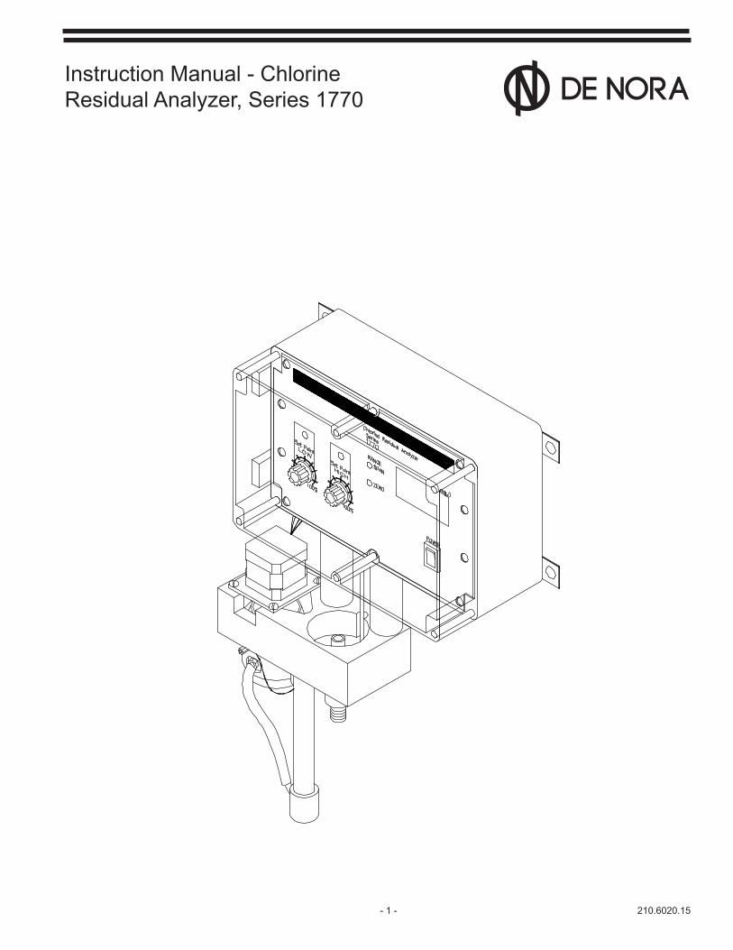
Instruction Manual - ChlorineResidual Analyzer, Series 1770
210.6020.15 - 2 -
These instructions describe the installation, operation and maintenance of the subject equipment. Failure to strictly follow these instructions can lead to an equipment rupture that may cause significant property damage, severe personal injury and even death. If you do not understand these instructions, please call De Nora Water Technologies for clarification before commencing any work at +1 215 997 4000 and ask for a Field Service Manager. De Nora Water Technologies, Inc. reserves the rights to make engineering refinements that may not be described herein. It is the responsibility of the installer to contact De Nora Water Technologies, Inc. for information that cannot be answered specifically by these instructions.
Any customer request to alter or reduce the design safeguards incorporated into De Nora Water Technologies equipment is conditioned on the customer absolving De Nora Water Technologies from any consequences of such a decision.
De Nora Water Technologies has developed the recommended installation, operating and maintenance procedures with careful attention to safety. In addition to instruction/operating manuals, all instructions given on labels or attached tags should be followed. Regardless of these efforts, it is not possible to eliminate all hazards from the equipment or foresee every possible hazard that may occur. It is the responsibility of the installer to ensure that the recommended installation instructions are followed. It is the responsibility of the user to ensure that the recommended operating and maintenance instructions are followed. De Nora Water Technologies, Inc. cannot be responsible deviations from the recommended instructions that may result in a hazardous or unsafe condition.
De Nora Water Technologies, Inc. cannot be responsible for the overall system design of which our equipment may be an integral part of or any unauthorized modifications to the equipment made by any party other that De Nora Water Technologies, Inc.
De Nora Water Technologies, Inc. takes all reasonable precautions in packaging the equipment to prevent shipping damage. Carefully inspect each item and report damages immediately to the shipping agent involved for equipment shipped “F.O.B. Colmar” or to De Nora Water Technologies for equipment shipped “F.O.B Jobsite”. Do not install damaged equipment.
DE NORA WATER TECHNOLOGIES, COLMAR OPERATIONSCOLMAR, PENNSYLVANIA, USAIS ISO 9001: 2008 CERTIFIED
READ THE ENTIRE MANUAL BEFORE OPERATING
USE ONLY IN ACCORDANCE WITH INSTRUCTION MANUAL
WARNING: HAZARDOUS VOLTAGES
PROTECTIVE GROUND (EARTH) TERMINAL
WARNING: FAILURE TO INSTALL, SET UP OR OPERATE THE CONTROLLER IN THE MANNER SPECIFIED BY DE NORA WATER TECHNOLOGIES MAY IMPAIR THE PROTECTION PROVIDED BY THIS EQUIPMENT.
- 3 - 210.6020.15
Table of Contents1 INTRODUCTION ...............................................................................................................................................5 1.1. General Description .............................................................................................................................5 1.2. EMC Testing .........................................................................................................................................5 1.3 Components .........................................................................................................................................5 1.4 Principal of Operation ...........................................................................................................................7 1.5 Chemistry of Chlorination .....................................................................................................................7 1.6 Galvanic Cell Theory ............................................................................................................................8
2 INSTALLATION ...............................................................................................................................................10 2.1 General ..............................................................................................................................................10 2.2 Wall Mounting.....................................................................................................................................10 2.3 Hydraulic Conditions ..........................................................................................................................12 2.4 Electrical .............................................................................................................................................13 2.5 Set Points .......................................................................................................................................... 16
3 START-UP .......................................................................................................................................................18 3.1 Quick Start Procedure ........................................................................................................................18 3.2 Range Selection .................................................................................................................................18 3.3 Measuring Chlorine (free), Iodine .......................................................................................................19 3.4 Conditioning the Analyzer ..................................................................................................................19
4 SERVICE .........................................................................................................................................................20 4.1 Cleaning ............................................................................................................................................ 20 4.2 Removing the Electrode Assembly for Service ................................................................................. 23 4.3 Thermistor ..........................................................................................................................................27 4.4 Calibration ......................................................................................................................................... 27 4.5 Alarm Set-up and Adjustment ........................................................................................................... 30 4.6 Motor and Drive ..................................................................................................................................30 4.7 Recommended Preventative Maintenance Procedure .......................................................................32
5 ACCESSORIES ..............................................................................................................................................33
6 TROUBLESHOOTING ....................................................................................................................................34 6.1 Troubleshooting Chart ........................................................................................................................34 6.2 Interferences of Free Chlorine Analyzer Measurements ....................................................................34
FIGURES 1 Series 1770 Chlorine Residual Analyzer ..............................................................................................6 2 Sample Flow Diagram ......................................................................................................................... 7 3 Dissociation Curve ...............................................................................................................................8 4 Dimensional Diagrams .......................................................................................................................10 5 Hydraulic Connections .......................................................................................................................12 6 PlumbingConfiguration ..................................................................................................................... 13 7 Electronics Module - Exploded View ..................................................................................................14 8 Main PC Board ...................................................................................................................................15 9 Jumper Positions ................................................................................................................................16 10 PC Board Front Assembly - Front View ............................................................................................ 17 11 PC Board Front Assembly - Installed View ....................................................................................... 17 12 Close-up of DIP Switches ................................................................................................................. 18 13 Close-up of Decimal Selector Jumper ............................................................................................... 18 14 Close-upofOverflowWeir .................................................................................................................20 15 Close-up of Flow Tube and Parts ...................................................................................................... 22 16 Gold Electrode Assembly ...................................................................................................................24 17 Motor/Striker Assembly ..................................................................................................................... 24 18 Internal Wiring Diagram .....................................................................................................................25 19 Recorder ............................................................................................................................................33 29 Flushing Y-strainer ............................................................................................................................ 33
210.6020.15 - 4 -
SAFETY
The recommended operating procedures have been designed with careful attention to safety. De Nora Water Technologies has made formal safety reviews of the initial design and any subsequent changes. This procedure is followed for all new products and covers areas in addition to those included in applicable safety standards. Regard-less of these efforts, it is not possible to eliminate all hazards from the equipment or to foresee every possible hazard which may occur. Safety is the responsibility of the user.
ThisequipmenthasbeendesignedinaccordancewithsafetyspecificationIEC1010-1andANSI/ISAS82.01andmeets the requirements for Class 1, Installation Category III equipment.
Observe the following precautions:
Observe all safety warnings marked on the equipment. These warnings identify areas of immediate hazard which could result in personal injury or loss of life.
Do not use this equipment for any purpose other than described in this instruction manual.
Disconnect power to the equipment prior to removing the face plate and making connections to the wiring terminals.
Do not operate the equipment with the face plate removed. Operation without the face plate presents an electrical shock hazard.
Use all practical safety precautions to prevent contact with energized parts of the equipment and related circuits.
Use the recommended connection procedures described elsewhere in this manual.
This equipment operates from a single phase power source. It requires a three-wire power cord. The voltage to ground from either pole of the power source must not exceed the maximum rated operating voltage, 240 Vac. Before making connection to the power source, determine that the voltage of the power source is correct. The power source must have a high rupture fuse or circuit breaker rated no higher than 15 amps.
DeNoraWaterTechnologiesrecommendsthatqualifiedpersonnelinstallandconnectthisequipment.Component replacementandinternaladjustmentsmustbemadebyqualifiedservicepersonnel.
The following warning and caution notices are used in this manual where applicable and should be strictly observed.
WARNING
Warning,asusedinthismanual,isdefinedasaconditionorpracticewhichcouldresultinpersonalinjuryor loss of life.
CAUTION
Caution,asusedinthismanual,isdefinedasaconditionorpracticewhichcouldresultindamagetoordestruction of this equipment.

- 5 - 210.6020.15
1 INTRODUCTION
1.1 General Description
1.1.1 SpecificationsInstrument Range: 0-1.0, 0-2.0, 0-5.0, 0-10.0, 0-20.0 mg/l.Analyzer Location: Indoor, as close as possible to the sample point to reduce sampling dead time.Resolution: 0.01 mg/l for ranges 0-5.0 and below; 0.1 for ranges 0-10.0 and above.Method: The amperometric analyzer is EPA approved for on-line residual chloride monitoring in drink-ing water.Power: 120/240 Vac, 50/60 Hz, single phase.Fuse: 0.5 AT, 250V (AC fuse), 5 x 20 mmPower Consumption: 11 wattsOutput Signal: 4-20 mAdc, isolated into 800 ohms maximum.Relay Contacts: 5 amps @240 Vac or 24 Vdc, resistive load SPDT.Sample Flow: 150ml/minute.Theminimumdesiredpressurefortheflowisabout5psig(0.3bar).Sample Supply: Continuous. Where sample interruption may be required, provisions must be made to keep the electrodes wet with fresh water.Speed of Response: 4 seconds from sample entry to display indication. 90% residual change 1 1/2 to 2 minutes.Ambient Temperature: 32° to 120° F (0° to 50° C)Sample Temperature: 32° to 120° F (0° to 50° C)Sample: Metal ions or certain corrosion inhibitors may affect analyzer operation. See page 35.Cathode: GoldAnode: CopperIndicator: 3-1/2 digit, LED display in milligrams per liter (mg/l)Accuracy: ± 5 % of rangeSensitivity: 0.01 mg/lElectronics Enclosure: NEMA 4Dimensions: 11" X 16.25" X 5" (279 mm X 413 mm X 127 mm)Shipping Weight: 12 lbs (5.5 kg)
1.2 EMC TestingThis instrument has been evaluated for RF interference over a frequency range of 80-1000 MHz and showed overall acceptable immunity. However, it may show a low level of susceptibility (as a negative signal offset) to radio frequency emissions as listed below. At 668-690 MHz, no interference will be seen unless the intensity ofthefieldstrengthexceeds1.3Volts/meter(V/m).Inallothercases,nointerferencewillbeseenunlesstheintensityofthefieldstrengthexceeds1.9V/m.
Frequencies (Vertical polarization only) 200-256 MHz 577-615 MHz 649-750 MHz
Interference of any duration will not effect the instrument's performance unsafely at any frequency. Prolonged or intermittent operation under conditions of RF interference will not damage the instrument components, or cause any irreversible effects in the instrument's operation.
210.6020.15 - 6 -
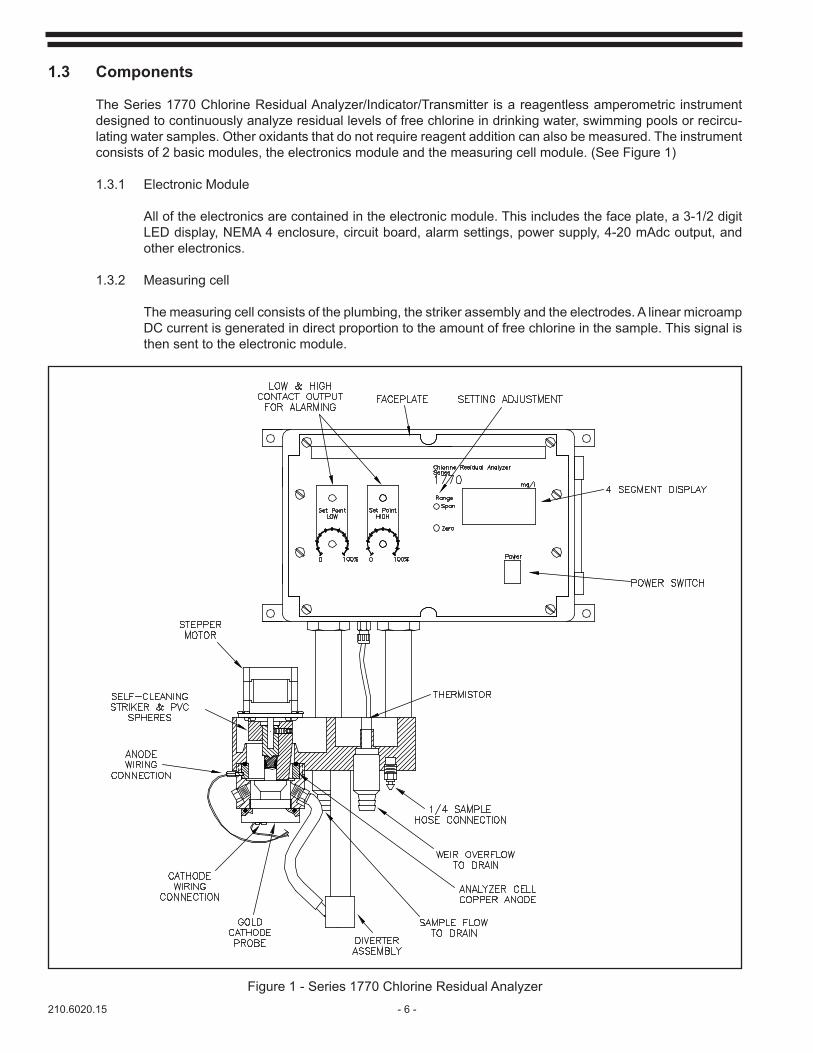
1.3 Components
The Series 1770 Chlorine Residual Analyzer/Indicator/Transmitter is a reagentless amperometric instrument designed to continuously analyze residual levels of free chlorine in drinking water, swimming pools or recircu-lating water samples. Other oxidants that do not require reagent addition can also be measured. The instrument consists of 2 basic modules, the electronics module and the measuring cell module. (See Figure 1)
1.3.1 Electronic Module
All of the electronics are contained in the electronic module. This includes the face plate, a 3-1/2 digit LED display, NEMA 4 enclosure, circuit board, alarm settings, power supply, 4-20 mAdc output, and other electronics.
1.3.2 Measuring cell
The measuring cell consists of the plumbing, the striker assembly and the electrodes. A linear microamp DC current is generated in direct proportion to the amount of free chlorine in the sample. This signal is then sent to the electronic module.
Figure 1 - Series 1770 Chlorine Residual Analyzer
- 7 - 210.6020.15
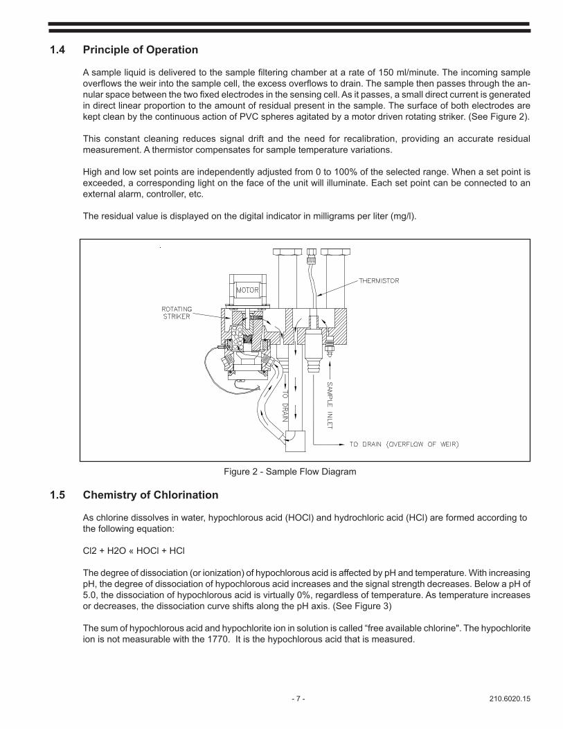
1.4 Principle of Operation
Asampleliquidisdeliveredtothesamplefilteringchamberatarateof150ml/minute.Theincomingsampleoverflowstheweirintothesamplecell,theexcessoverflowstodrain.Thesamplethenpassesthroughthean-nularspacebetweenthetwofixedelectrodesinthesensingcell.Asitpasses,asmalldirectcurrentisgeneratedin direct linear proportion to the amount of residual present in the sample. The surface of both electrodes are kept clean by the continuous action of PVC spheres agitated by a motor driven rotating striker. (See Figure 2).
This constant cleaning reduces signal drift and the need for recalibration, providing an accurate residual measurement. A thermistor compensates for sample temperature variations.
High and low set points are independently adjusted from 0 to 100% of the selected range. When a set point is exceeded, a corresponding light on the face of the unit will illuminate. Each set point can be connected to an external alarm, controller, etc.
The residual value is displayed on the digital indicator in milligrams per liter (mg/l).
Figure 2 - Sample Flow Diagram
1.5 Chemistry of Chlorination
As chlorine dissolves in water, hypochlorous acid (HOCl) and hydrochloric acid (HCl) are formed according to the following equation:
Cl2 + H2O « HOCl + HCl
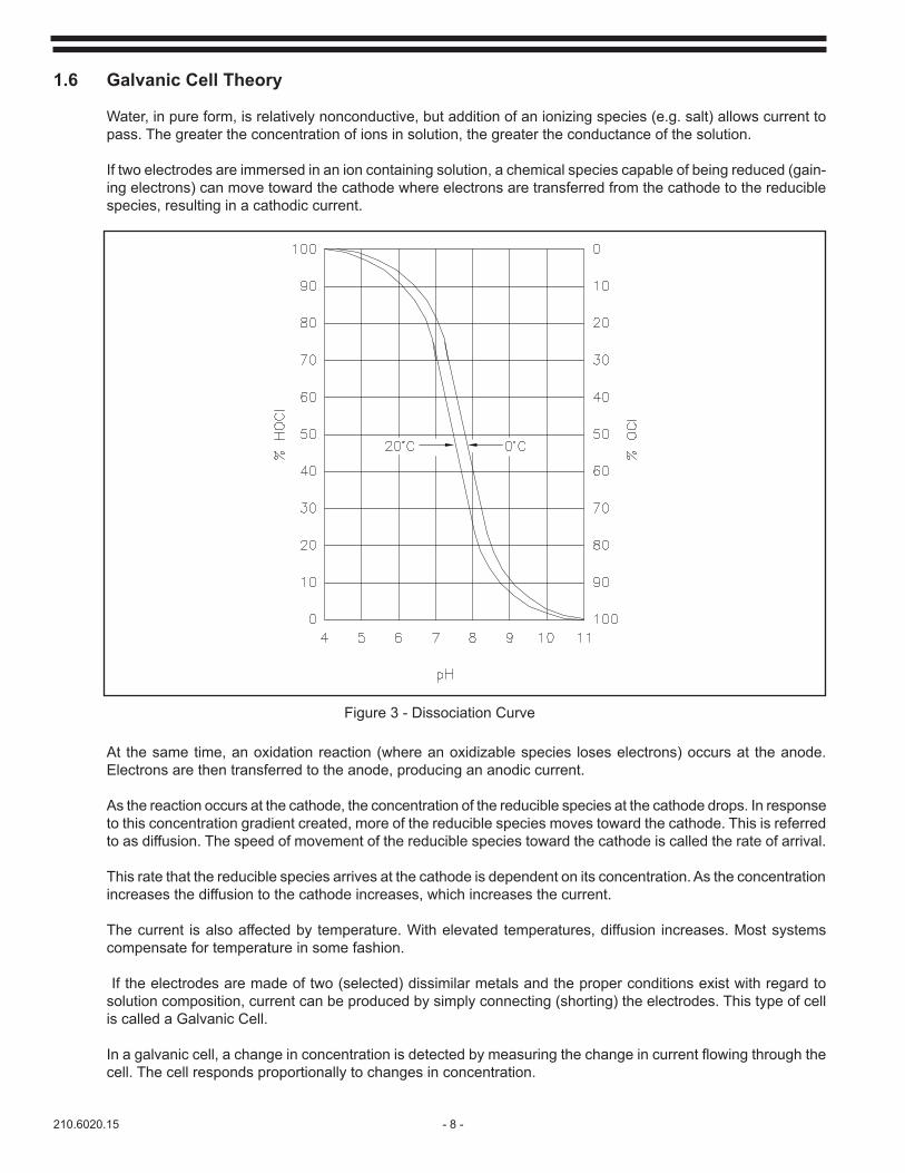
The degree of dissociation (or ionization) of hypochlorous acid is affected by pH and temperature. With increasing pH, the degree of dissociation of hypochlorous acid increases and the signal strength decreases. Below a pH of 5.0, the dissociation of hypochlorous acid is virtually 0%, regardless of temperature. As temperature increases or decreases, the dissociation curve shifts along the pH axis. (See Figure 3)
The sum of hypochlorous acid and hypochlorite ion in solution is called “free available chlorine". The hypochlorite ion is not measurable with the 1770. It is the hypochlorous acid that is measured.
210.6020.15 - 8 -
1.6 Galvanic Cell Theory
Water, in pure form, is relatively nonconductive, but addition of an ionizing species (e.g. salt) allows current to pass. The greater the concentration of ions in solution, the greater the conductance of the solution.
If two electrodes are immersed in an ion containing solution, a chemical species capable of being reduced (gain-ing electrons) can move toward the cathode where electrons are transferred from the cathode to the reducible species, resulting in a cathodic current.
Figure 3 - Dissociation Curve
At the same time, an oxidation reaction (where an oxidizable species loses electrons) occurs at the anode. Electrons are then transferred to the anode, producing an anodic current.
As the reaction occurs at the cathode, the concentration of the reducible species at the cathode drops. In response to this concentration gradient created, more of the reducible species moves toward the cathode. This is referred to as diffusion. The speed of movement of the reducible species toward the cathode is called the rate of arrival.
This rate that the reducible species arrives at the cathode is dependent on its concentration. As the concentration increases the diffusion to the cathode increases, which increases the current.
The current is also affected by temperature. With elevated temperatures, diffusion increases. Most systems compensate for temperature in some fashion.
If the electrodes are made of two (selected) dissimilar metals and the proper conditions exist with regard to solution composition, current can be produced by simply connecting (shorting) the electrodes. This type of cell is called a Galvanic Cell.
Inagalvaniccell,achangeinconcentrationisdetectedbymeasuringthechangeincurrentflowingthroughthecell. The cell responds proportionally to changes in concentration.
- 9 - 210.6020.15
The cathode in the galvanic cell used in the 1770 Chlorine Analyzer is gold. When hypochlorous acid is present in solution, electrons are exchanged at the cathode surface and chloride ions are produced.
HOCl + 2e- « Cl- + OH-
The anode is copper. As electrons are exchanged, an oxide product remains on the anode. Because of this, an abrasion mechanism (constant stirring of cleaning spheres) is incorporated to strip the oxide product off the metal surface.Sincecopperisconsumedintheprocess,thetermsacrificialanodeisappliedtothecopperelectrode.
CurrentflowintheamperometriccellisaffectedbychangesinpH.Thecellcurrentismoststablebetween4and4.5 pH. However, an accurate ( ± 5%) signal is produced at any pH levels up to 9.5 pH. The instrument provides excellent stability. If the application requires a more stable signal or a signal that can detect low parts per billion levels, De Nora Water Technologies recommends the Series CL1000 Residual Analyzer. This analyzer uses a reference electrode and a pH buffering solution in the cell to stabilize cell current.
Temperature compensation circuitry is employed to counter the affects of diffusion and other factors that are affected by temperature.
When measuring free chlorine, combined chlorine is not measured. However, some interference may occur if free chlorine is measured in the presence of a high level of chloramines.
210.6020.15 - 10 -
2 INSTALLATION
2.1 General
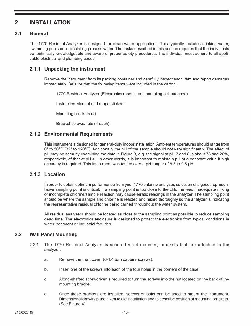
The 1770 Residual Analyzer is designed for clean water applications. This typically includes drinking water, swimming pools or recirculating process water. The tasks described in this section requires that the individuals be technically knowledgeable and aware of proper safety procedures. The individual must adhere to all appli-cable electrical and plumbing codes.
2.1.1 Unpacking the instrument
Remove the instrument from its packing container and carefully inspect each item and report damages immediately. Be sure that the following items were included in the carton.
1770 Residual Analyzer (Electronics module and sampling cell attached)
Instruction Manual and range stickers
Mounting brackets (4)
Bracket screws/nuts (4 each)
2.1.2 Environmental Requirements
This instrument is designed for general-duty indoor installation. Ambient temperatures should range from 0°to50°C(32°to120°F).AdditionallythepHofthesampleshouldnotvarysignificantly.TheeffectofpH may be seen by examining the data in Figure 3, e.g. the signal at pH 7 and 8 is about 73 and 28%, respectively, of that at pH 4. In other words, it is important to maintain pH at a constant value if high accuracy is required. This instrument was tested over a pH ranger of 6.5 to 9.5 pH.
2.1.3 Location
In order to obtain optimum performance from your 1770 chlorine analyzer, selection of a good, represen-tative sampling point is critical. If a sampling point is too close to the chlorine feed, inadequate mixing or incomplete chlorine/sample reaction may cause erratic readings in the analyzer. The sampling point should be where the sample and chlorine is reacted and mixed thoroughly so the analyzer is indicating the representative residual chlorine being carried throughout the water system.
All residual analyzers should be located as close to the sampling point as possible to reduce sampling dead time. The electronics enclosure is designed to protect the electronics from typical conditions in water treatment or industrial facilities.
2.2 Wall Panel Mounting
2.2.1 The 1770 Residual Analyzer is secured via 4 mounting brackets that are attached to the analyzer.
a. Remove the front cover (6-1/4 turn capture screws).
b. Insert one of the screws into each of the four holes in the corners of the case.
c. Along-shafted screwdriver is required to turn the screws into the nut located on the back of the mounting bracket.
d. Once these brackets are installed, screws or bolts can be used to mount the instrument. Dimensional drawings are given to aid installation and to describe position of mounting brackets. (See Figure 4)
- 11 - 210.6020.15
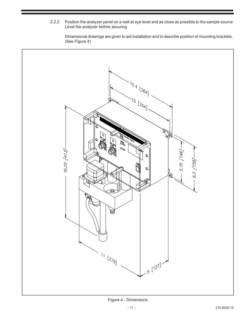
Figure 4 - Dimensions
2.2.2 Position the analyzer panel on a wall at eye level and as close as possible to the sample source Level the analyzer before securing.
Dimensional drawings are given to aid installation and to describe position of mounting brackets. (See Figure 4)

210.6020.15 - 12 -
2.3 Hydraulic Connections
2.3.1 Connect a length of 1/2" drain hose to the two drain outlets on the analyzer. Route the hoses to main- tain a gravity fed drain (downward slope). (See Figure 5)
2.3.2 Connect one end of the 1/4" sample supply tubing to the source using the 1/4" barbed connector. (See Figure 5)
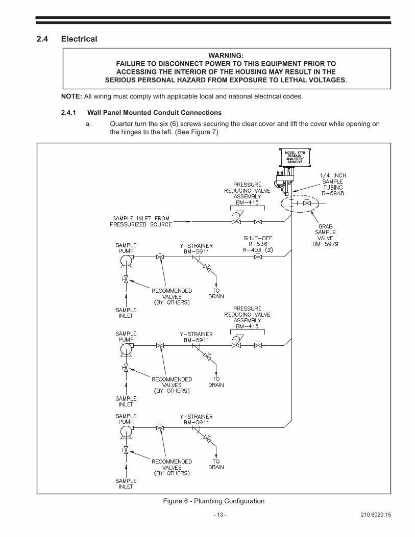
Atypicalinstallationmayrequireasamplepumpifthepressureandflowarelowand/oraY-strainerto remove any large particulates that may enter the system. There may also be a need for pressure reducing valves if the sample pressure is too high or the sample pump needs to be regulated. The pres-surereachingtheanalyzershouldprovideaflowof150ml/min.Theminimumdesiredpressurefortheflowisabout5psig(0.3bar).Thesampletubingisratedto55psig(3.8bar).Additionally,mostin-linesample connection systems will include a valve assembly for grab sampling for calibration checks on the analyzer or other chemical tests. (See Figure 6)
Whensettinguptheflowrateobservetheoverflowweir.Thesamplepressureshouldnotcreateaverticalstreamofwater,butshouldcreatearollingofthewaterintheweir.Theflowshouldnotcausewatertospilloverthesidesoftheanalyzer.Adjusttheflowaccordingly.Figure6describesatypicalinstallationforhydraulicsandflow.
Figure 5 - Hydraulic Connections
- 13 - 210.6020.15
2.4 Electrical
WARNING: FAILURE TO DISCONNECT POWER TO THIS EQUIPMENT PRIOR TO ACCESSING THE INTERIOR OF THE HOUSING MAY RESULT IN THE
SERIOUS PERSONAL HAZARD FROM EXPOSURE TO LETHAL VOLTAGES.
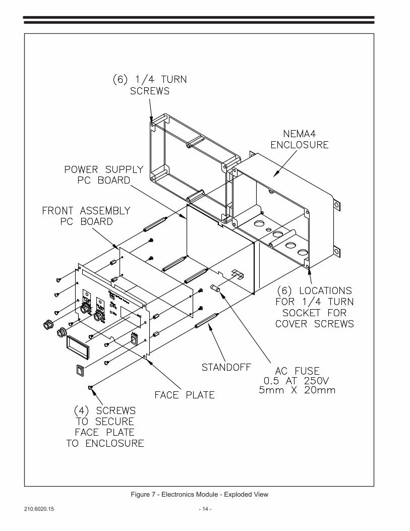
NOTE: All wiring must comply with applicable local and national electrical codes. 2.4.1 Wall Panel Mounted Conduit Connections a. Quarter turn the six (6) screws securing the clear cover and lift the cover while opening on the hinges to the left. (See Figure 7)
Figure6-PlumbingConfiguration
210.6020.15 - 14 -
Figure 7 - Electronics Module - Exploded View

- 15 - 210.6020.15
b. Remove four (4) screws securing the face plate. Remove the face plate. (See Figure 7)
c. Set the two (2) line voltage jumpers to the proper voltage. (See Figure 8)
WARNINGPOWER FOR THE ANALYZER SHOULD BE SUPPLIED
FROM A HIGH BREAKING CAPACITY FUSED DISCONNECT LOCATED IN CLOSE PROXIMITY TO THE UNIT.
d. Route the power line from the analyzer through the bottom right opening and connect to the L1, L2 and G terminals. (See Figure 8)
e. If required connect current output and alarm contacts. (See Figure 8)
NOTE: Do not run line voltage and low level signal voltage in the same conduit.
f. Replace face plate assembly and secure the clear cover.
Figure 8 - Main PC Board
120 Vac 240 Vac
L1 Live Black Brown
L2 Neutral White Blue
G Ground Green Green/Yellow
210.6020.15 - 16 -
2.4.2 PowerThe voltage jumpers must be properly positioned before power is applied. See Section 2.4.1.
This instrument is shipped with the jumper positions in either the 120 or 240 Vac position. If you are using a different power source, other than the one indicated, make sure you position the jumpers correctly. (See Figure 8)
2.5 Set Points High and low set point adjustment knobs are located on the front of the unit. To set the alarm points, proceed as follows:
2.5.1 AlarmVerify that the range sticker corresponds with the range selected. See section 3A for proper range selection dip switch settings. If the range is not indicated, is incorrect or is missing, select the correct sticker, included with your unit, and place it on the front of the unit in the space provided. In order to establish your set points, you must know the instrument’s range.
a. Verify selection of the high alarm (see Figures 9 and 11). The alarm is factory set to the high alarm mode. The alarm for high will energize above set point and the alarm for low will energize below set point. b. Determine the high and low milligram per liter value at which you want the analyzer to alarm. Tofigurethesepercentages,usethefollowingformula: (Alarm point) ÷ range X 100 = % set point c. Set the low set point to the percentage value for the low alarm point and the high set point to the percentage value for the high alarm point.
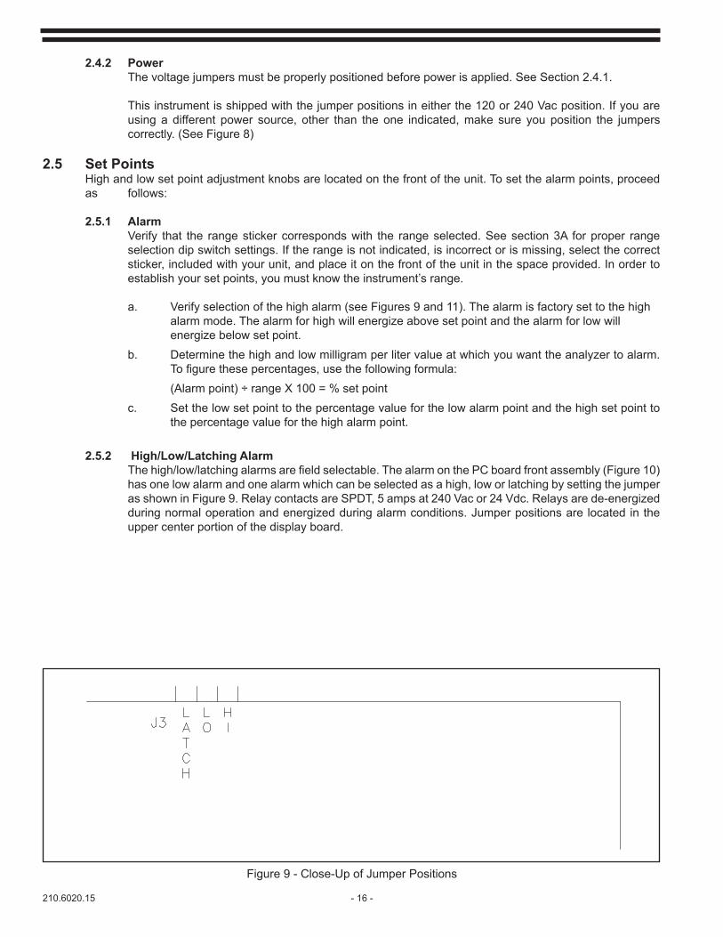
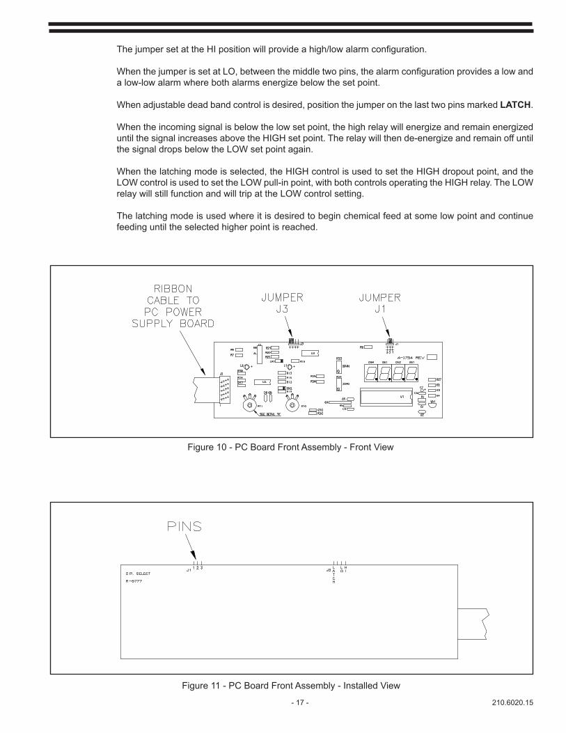
2.5.2 High/Low/Latching AlarmThehigh/low/latchingalarmsarefieldselectable.ThealarmonthePCboardfrontassembly(Figure10)has one low alarm and one alarm which can be selected as a high, low or latching by setting the jumper as shown in Figure 9. Relay contacts are SPDT, 5 amps at 240 Vac or 24 Vdc. Relays are de-energized during normal operation and energized during alarm conditions. Jumper positions are located in the upper center portion of the display board.
Figure 9 - Close-Up of Jumper Positions
- 17 - 210.6020.15
ThejumpersetattheHIpositionwillprovideahigh/lowalarmconfiguration.
WhenthejumperissetatLO,betweenthemiddletwopins,thealarmconfigurationprovidesalowanda low-low alarm where both alarms energize below the set point.
When adjustable dead band control is desired, position the jumper on the last two pins marked LATCH.
When the incoming signal is below the low set point, the high relay will energize and remain energized until the signal increases above the HIGH set point. The relay will then de-energize and remain off until the signal drops below the LOW set point again.
When the latching mode is selected, the HIGH control is used to set the HIGH dropout point, and the LOW control is used to set the LOW pull-in point, with both controls operating the HIGH relay. The LOW relay will still function and will trip at the LOW control setting.
The latching mode is used where it is desired to begin chemical feed at some low point and continue feeding until the selected higher point is reached.
Figure 10 - PC Board Front Assembly - Front View
Figure 11 - PC Board Front Assembly - Installed View
210.6020.15 - 18 -
3 START-UP 3.1 Quick Start Procedure
WARNINGFAILURE TO DISCONNECT POWER TO THIS EQUIPMENT PRIOR
TO ACCESSING THE INTERIOR OF THE HOUSING MAY RESULT IN THE SERIOUS PERSONAL HAZARD FROM EXPOSURE TO LETHAL VOLTAGES.
3.1.1 Mount and level the analyzer. 3.1.2 Connect sample and drain lines. 3.1.3 Check range of analyzer. 3.1.4 Plug analyzer into power (check voltage switches 120 or 240 Vac). 3.1.5 Run sample to analyzer (no fountain, smooth over weir). 3.1.6 Turn on analyzer. 3.1.7 Stabilize for 24 hours. 3.1.8 Check readings against amperometric titrator. 3.1.9 Zero analyzer on process water before chlorination. 3.1.10 Span analyzer on known chlorinated sample.
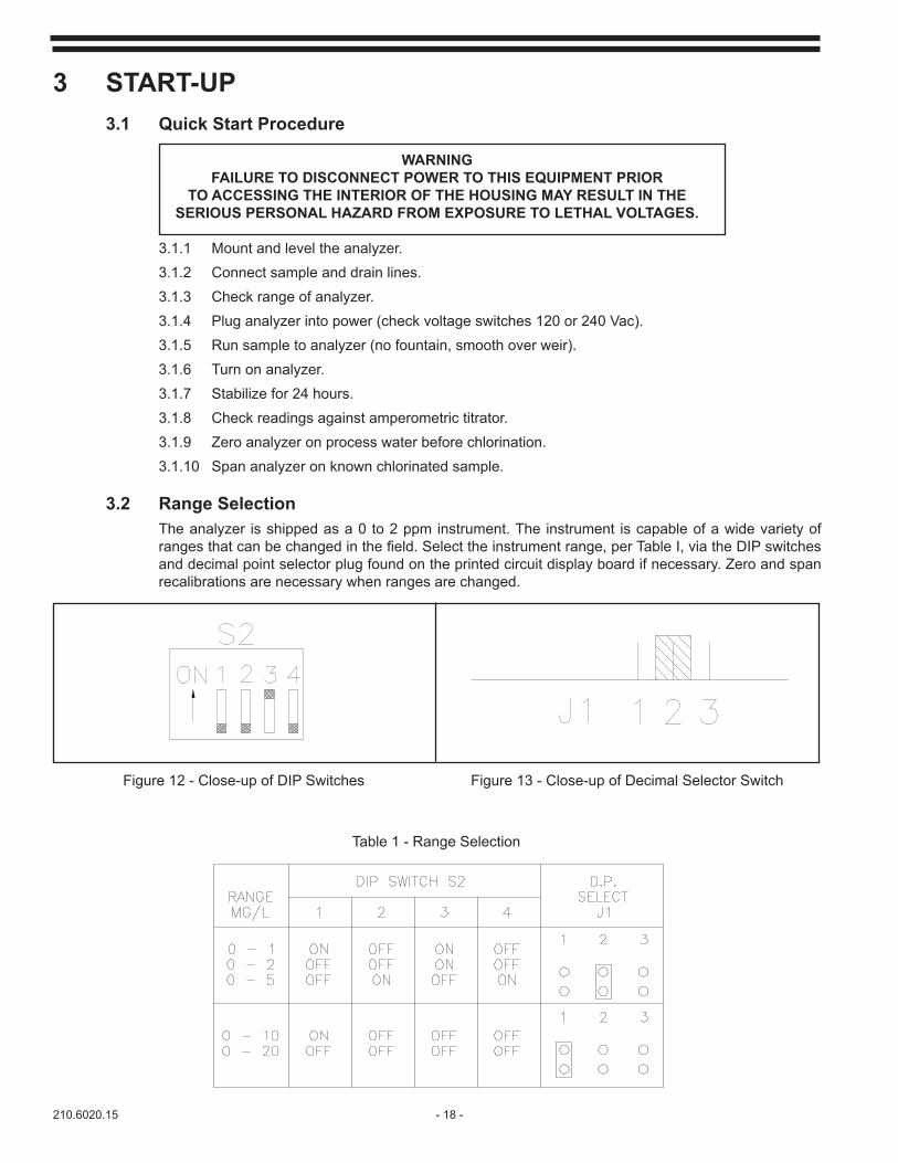
3.2 Range Selection The analyzer is shipped as a 0 to 2 ppm instrument. The instrument is capable of a wide variety of rangesthatcanbechangedinthefield.Selecttheinstrumentrange,perTableI,viatheDIPswitchesand decimal point selector plug found on the printed circuit display board if necessary. Zero and span recalibrations are necessary when ranges are changed.
Figure 12 - Close-up of DIP Switches Figure 13 - Close-up of Decimal Selector Switch
Table 1 - Range Selection

- 19 - 210.6020.15
The DIP switches are located on the upper left corner of the main PC board (see Figure 12) and the decimal jumper is located along the upper edge of the display board (see Figure 13). If ranges are changed, the paste on labels on the front plate must also be changed, using the labels provided. After range is selected, mark internal label for future reference.
3.3. Measuring Chlorine (free), IodineThis analyzer is a reagentless system. No chemicals are necessary when measuring free halogens in drinking water applications. Additionally, this instrument will not measure total chlorine or chloramines. The instrument must be re-calibrated to measure the target oxidant. If you require a system to be placed in applications where the pH varies considerably or in applications that require total oxidants, stop and consult a De Nora Water Technologies Representative to advise as to the best product to meet your needs.
3.4. Conditioning the Analyzer3.4.1 Startthewatersampleflowofapproximately150ml/minute(1pint/minute).Watermustbe flowingovertheoverflowweirinthesamplefilterchambertodrain.
3.4.2 The sample must be supplied continuously for reliable operation. If the system requires occasional cutoff, provisions must be made to keep the electrodes wet.
3.4.3 Samplingfromapressurizedsourcemayrequiredapressurereducingvalvetoholdtheflow constant. Maximum desired pressure is 5 psi (0.3 bar).
3.3.4 If sampling froma turbidwater source, a flushingY-strainermaybenecessary to prevent sample line frombeingplugged.Other typesoffilterarenot recommended.Seeaccessory section.
3.4.5 Turn ON power to the analyzer.
NOTE: Observe motor rotation at striker. Striker should move from left to right (counterclockwise). If rotation is reversed, turn the power off for a few seconds and then back on.
3.4.6 Ifairbubblesarepresentintheflowtubing,squeeze,tap,ordisconnecttubingattheanalyzer andflushmomentarily.
3.4.7 The analyzer requires a minimum stabilization time of 24 hours with chlorinated water running through the analyzer cell.
3.4.8 After stabilization, calibration may begin.
210.6020.15 - 20 -
4 SERVICENOTE: DUE TO THE NATURE OF THIS EQUIPMENT AND THE USE OF THE CUSTOM-BUILT ELEMENTS, IT IS RECOMMENDED THAT THIS EQUIPMENT BE RETURNED TO THE FACTORY FOR REPAIR OR REPLACEMENT IF FOUND TO BE DEFECTIVE IN FORM OR FUNCTION.
4.1 CleaningFrequency of cleaning the analyzer is greatly affected by the condition of the water. The following should be cleaned as indicated:
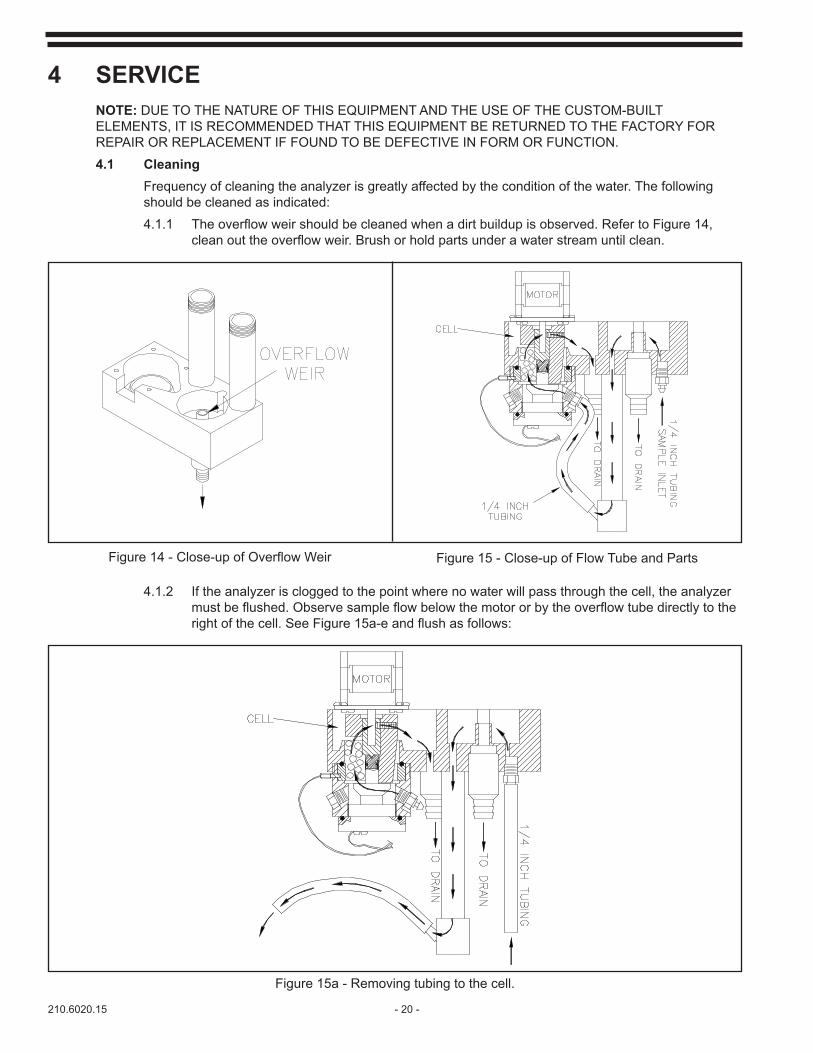
4.1.1 Theoverflowweirshouldbecleanedwhenadirtbuildupisobserved.RefertoFigure14, cleanouttheoverflowweir.Brushorholdpartsunderawaterstreamuntilclean.
Figure14-Close-upofOverflowWeir Figure 15 - Close-up of Flow Tube and Parts
4.1.2 If the analyzer is clogged to the point where no water will pass through the cell, the analyzer mustbeflushed.Observesampleflowbelowthemotororbytheoverflowtubedirectlytothe rightofthecell.SeeFigure15a-eandflushasfollows:
Figure 15a - Removing tubing to the cell.

- 21 - 210.6020.15
Figure 15b - Remove sample line tubing and temporarily reinstall directly into the cell.
Figure15c-Adjustsamplelineforhighflowrateuntilthecellisflushedout.
210.6020.15 - 22 -
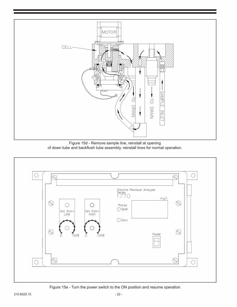
Figure 15d - Remove sample line, reinstall at openingofdowntubeandbackflushtubeassembly.reinstalllinesfornormaloperation.
Figure 15e - Turn the power switch to the ON position and resume operation.

- 23 - 210.6020.15
4.2 Removing the Electrode Assembly for ServiceIf the signal becomes erratic and will not hold calibration, the entire wet end may be removed for service. When servicing the wet end of the analyzer, to include the motor, it is easier to remove the entire assembly as a single unit rather than to remove each piece while the analyzer is on the wall.
4.2.1 Removing the Wet End Unita. Turn the power switch to the off position and disconnect the power cord if the unit is not hard wired. If hardwired, pull circuit breaker.b. Turn off the water sample line.c. Remove the drain lines.d. Remove the four screws at the corners of the front panel.e. Remove the front panel and disconnect the ribbon cable connector. The power switch may remain connected.f. Remove wires from screw terminals at motor connections BL, R, BK, and G at electrode terminals + (yellow) and - (brown) labeled “IN" and at the thermistor terminals labeled “T". (See Figure 18)g. Remove conduit connector nuts from inside the case and remove the entire electrode and motor assembly.
4.2.2 Gold Electrode RemovalNormallifeofthegoldelectrodeisthreetofiveyears.Thiscanvarydependinguponthechemicalresidualand the quality of the water. The gold electrode should appear clean and shiny.When repairing or cleaning the gold electrode it is easier to remove the entire wet end assembly rather than service the electrode with the wet end attached to the electronic module. See section 4.2.1 for removal of the wet end. Once the wet end is removed proceed as follows:a. Invert the wet end assembly to drain the water out and place on the work surface inverted.b. Disconnect the yellow wire from the bottom of the assembly.c. Unscrew the gold electrode assembly and carefully dump the 100 PVC spheres into a container for reuse.d. Inspect the condition of the electrode. Clean and polish with water and a clean cloth. If the electrode cannot be polished with water, acid or detergents may be used. Do not use any abrasive materials. If the electrode is damaged it must be replaced. e. If the electrode needs to be replaced, place the large O-ring in the groove on the new electrode assembly and screw the assembly into the bottom body, by hand, until snug. See Figure 16 for gold electrode assembly.
210.6020.15 - 24 -
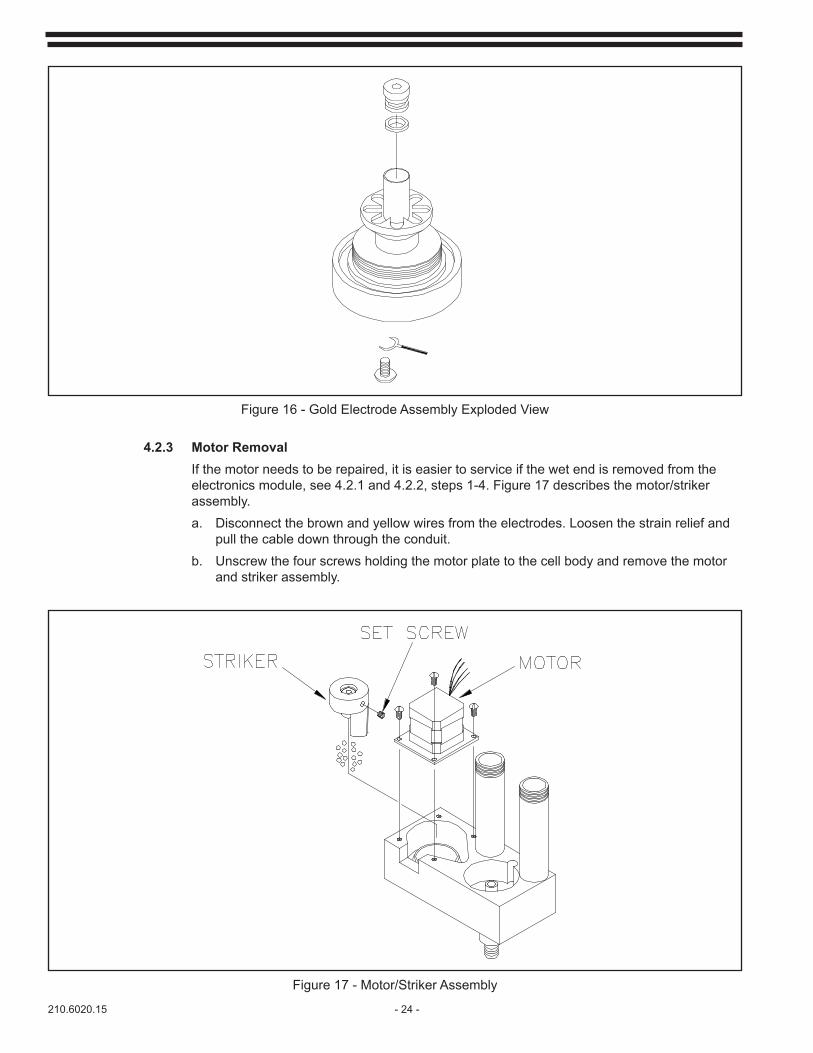
Figure 16 - Gold Electrode Assembly Exploded View
4.2.3 Motor Removal If the motor needs to be repaired, it is easier to service if the wet end is removed from the electronics module, see 4.2.1 and 4.2.2, steps 1-4. Figure 17 describes the motor/striker assembly. a. Disconnect the brown and yellow wires from the electrodes. Loosen the strain relief and pull the cable down through the conduit. b. Unscrew the four screws holding the motor plate to the cell body and remove the motor and striker assembly.
Figure 17 - Motor/Striker Assembly
- 25 - 210.6020.15
c. If the motor needs to be replaced, remove the striker from the motor shaft. Install the striker on the new motor by positioning the striker so it will be just off the bottom of the assembly. Follow 4.2.5 for striker alignment.d. Turnthesetscrewinthestrikeruntilitcontactstheflatsectionofthemotorshaft.See Figure 17.
4.2.4. Copper ElectrodeThe copper electrode is not removable from its housing unless the cell assembly is complete-ly disassembled. If the copper electrode needs to be replaced refer to the parts list at the end of this manual for a diagram of assembly and disassembly. Make sure the cell gasket is in place during assembly.It is recommended that any maintenance on the copper electrode be performed while the electrode is installed in the cell housing.a. Remove the motor and gold electrode from the cell housing. Refer to sections 4.2.1, 4.2.2, and 4.2.3.b. With the copper electrode installed in the cell housing, clean the cell with detergent and a non-metallic scouring pad.c. Avoidtheuseofacids,solventbasedchemicalcoppercleanersorfinemetallicabrasive paper as they may leave a residue that can cause large signal errors.
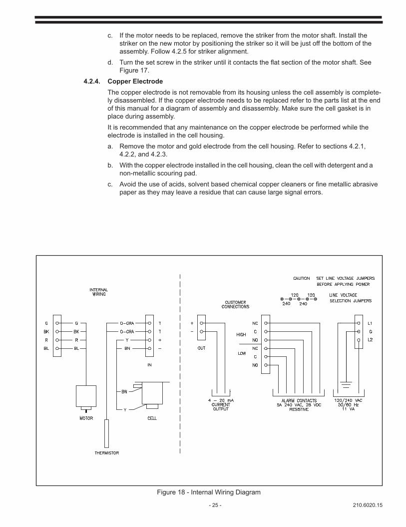
Figure 18 - Internal Wiring Diagram
210.6020.15 - 26 -
4.2.5 Striker Alignment
Before reinstalling the motor, the alignment of the striker should be checked. The alignment of the striker assembly is critical for proper cleaning of the electrodes. Always check striker alignment after removing the motor or the gold electrode.
a. Loosen striker on shaft with a 3/16" hex key wrench.
b. Temporarily install the gold electrode and screw it down tight by hand.
c. With a screwdriver, slide the striker down the motor shaft until it bottoms out in the cell housing. Tighten striker on shaft using the set screw (see Figure 17).
d. Check for binding by rotating striker by hand. Striker should turn easily.
e. Remove the gold electrode.
4.2.6 Motor Re-assembly
a. Reinstall the motor in the cell housing.
b. Make sure that the motor leads face towards the rear of the housing.
c. When the motor assembly seats easily, secure with 4 screws.
4.2.7 Gold Electrode Re-assembly
a. With the wet end assembly inverted, replace the PVC spheres into the bottom of the cell housing. Check that no spheres are seated on the striker bottom.
b. Reinstall the gold electrode and hand tighten.
c. Check the small screw on the side of the copper electrode and re-tighten if necessary. Secure small nut.
d. Reconnect cell wires. The brown to the copper electrode on the side of the assembly and the yellow to the gold electrode on the bottom of the assembly.
e. After depositing spheres and securing the motor/striker assembly and electrodes, rotate the motor/striker assembly by hand, checking for rubbing. The striker can be observed below the motor. If the striker is not rotating, realign the striker.
4.2.8 Reinstallation
a. Reinstall the temperature thermistor in the black receptacle.
b. Reinstall the electrode assembly to the electronics module using the two conduit nuts.
c. Reconnect the wires according to the internal wiring diagram. (See Figure 18)
NOTE: Connect the yellow wire to the + IN and the brown wire to the - IN terminals.
d. Reconnect the front panel and secure with four screws. Make sure that all 6 1/4 turn screws are securely fastened to prevent water from entering the electronics module.
e. Reinstallthedrainandsamplelinesandstartthesampleflowing.
- 27 - 210.6020.15
f. Turn on the power and observe the motor rotation at the striker. The striker should move counterclockwise. If not, turn the power off for a few seconds and then back on. Check that the rotation is smooth with no PVC spheres jamming under the striker.
g. Run the analyzer with chlorinated water for 24 hours and then re-calibrate.
4.3 Thermistor
Failure of the thermistor will appear as an excessively high or low signal. Proceed as follows for testing and replacement. Refer to Figure 18.
4.3.1 Remove the two (2) thermistor wires from terminals T1 and T2, and remove the thermistor.
4.3.2 Connect an ohm meter to the thermistor wires. If the ohm meter shows a stable resistance reading between 2k and 4k, the thermistor is not defective. If the ohm meter shows low ohms, iserraticorgoestoinfinity,thethermistorisdefectiveandmustbereplaced.Recalibrationis required. See Calibration section 4.4.
4.4. Calibration
Instruments are calibrated at the factory but still require zero and span adjustment to compensate for the composition of the background water. Ranges must be switched with the range selection DIP switches before recalibration. The same calibration procedure is to be followed for measurement of any residual.
Clean the electrodes according to section 4.2 if the signal becomes erratic and cannot be calibrated.
4.4.1 Zero and Span Calibration
Equipment required: small screwdriver
NOTE: Cross checking calibration should be performed with an amperometric titrator. Amper-ometric titration is proven to be the most accurate and reliable of all methods used for chlorine determination. Although the DPD colorimetric method is subject to a number of interferences it willprovidesufficientaccuracyinmostinstallationsforacrosscheck.
Set the analyzer for the desired range using the DIP switches per Table I, in the Start-up section, and place the correct range label on the front panel.
a. With the power ON, run sample water through the analyzer cell for 24 hours to condition the cell.
b. After cell conditioning, run untreated (zero residual) water through the analyzer cell. Allow one (1) hour for stabilization. If untreated water is unavailable, prepare a reservoir of chlorine free water according to section 4.2.2.
c. Adjust the ZERO control until the digital display reads 000 mg/l.
d. Run a water sample of known residual value through the analyzer and allow one (1) hour for full stabilization.
e. Adjust the SPAN control until the digital display reads the value of the known sample.
4.2.2 Preparation of Zero Standard
The proper zero standard is critical in the calibration process. If this zero standard is not prepared properly and some chlorine remains the calibration will not hold and low level chlorine readings will not be possible. The following steps will detail the proper procedures used for preparing, verifying and installing your zero standard.
210.6020.15 - 28 -
Chlorine-free/chlorine-demand-free water
This method is preferred because background interferences will be calibrated out.
a. Collect chlorinated process water in a plastic container of 8-20 liters. (For pure chlorinated water, obtain good quality deionized water and add enough chlorine to make a 5 ppm free chlorine solution and proceed with steps 2-5.)
b. Let container stand 2 days. Check the chlorine level.
c. Remove the remaining chlorine by placing the container in sunlight or irradiating with a UV lamp.
d. Verify chlorine levels using a total chlorine DPD test.
e. Stable for several weeks unless bacterial growth occurs.
aa. Normal chlorine free sample - Method 1
1] Prepare zero chlorine reference by adding 4 ml of .250N Ferrous Ammonium Sulfate (FAS) to 4 liters of normal sample
2] Verify chlorine levels using the DPD colorimetric method. Keep adding .250N FAS untilthechlorineisverifiedaszeroppm.
bb. Setting up the reservoir
1] Once the chlorine free water has been prepared, place a container of zero reference waterabovetheanalyzerwithenoughheadtoestablisha150ml/minflowrate.
2] Stoptheflowtotheanalyzerandtheeffluentfromtheanalyzerandlettheanalyzer run with the zero water in the cell for one hour.
3] Afteraonehourstabilization,restarttheflowtotheanalyzerandproceedwithstepc of section 4.4.1.
cc. Normal chlorine-free sample - Method 2
1] Installactivatedcarbonfilterandaby-passvalveinthesampleline.
2] Whenperformingzerospan,routethesamplethroughthecharcoalfilter.
3] Verify the zero chlorine using a DPD test.
4.4.3 Coarse Span Adjustment
IfthereisinsufficientfrontpanelSPANadjustment,aninternalcoarseSPANadjustment(CS)has been provided. Coarse span is located at the upper left corner of the main PC board. (See Figure 8).
4.4.4 Output Signal Adjustment
Equipment required: small screwdriver and calibrated recorder on output.
- 29 - 210.6020.15
The Z2 and SP2 controls on the internal printed circuit board may require adjustment if the receiving recorder or controller does not match the front panel display. The output signal may be calibrated with or without chlorinated sample running through the cell.
a. Preliminary
1. Open the front panel and temporarily remove jumpers on the J1 pin header on the main PC board. (See Figure 8)
2. Note and record the value on the front panel display.
3. Readjust front panel ZERO potentiometer to read 000 mg/l on the front panel display.
b. Method 1
On-line calibration to match receiving signal
1. Adjust Z2 potentiometer to read 0 mg/l on receiving device.
2. Reconnect jumpers to J1 pin header.
3. Using incoming signal and front panel ZERO potentiometer, adjust Zero to read more than 50% of selected range on front panel display.
NOTE: If Zero adjustment is inadequate, front panel SPAN or internal coarse span may also be used. The analyzer will require recalibration to a titrated standard afterwards.
4. With the display reading more than 50% of the selected range, adjust SP2 pot on main PC board until the receiving device reading matches the front panel display of the analyzer.
NOTE: If the SPAN or coarse span potentiometers have not been disrupted, the original calibration of the analyzer can be restored as follows:
5. Remove jumpers on the J1 pin header and readjust front panel ZERO pot to read the value originally recorded. Then reinstall jumpers.
c. Method 2
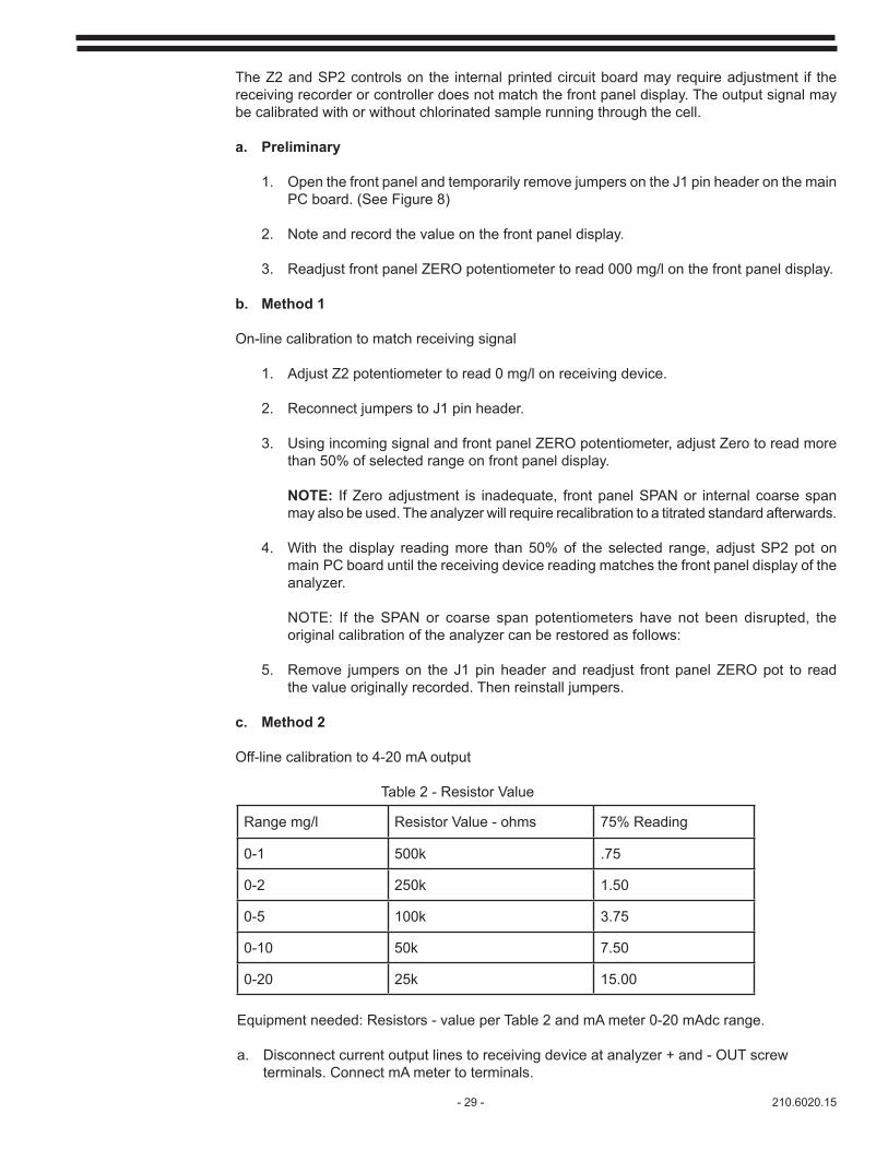
Off-line calibration to 4-20 mA output
Table 2 - Resistor Value
Range mg/l Resistor Value - ohms 75% Reading
0-1 500k .75
0-2 250k 1.50
0-5 100k 3.75
0-10 50k 7.50
0-20 25k 15.00
Equipment needed: Resistors - value per Table 2 and mA meter 0-20 mAdc range.
a. Disconnect current output lines to receiving device at analyzer + and - OUT screw terminals. Connect mA meter to terminals.
210.6020.15 - 30 -
b. Adjust Z2 potentiometer on main PC board to read 4.00 mAdc.
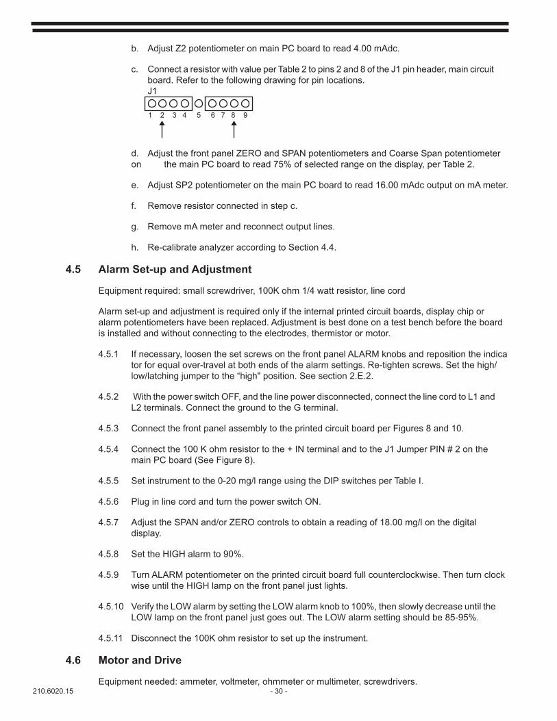
c. Connect a resistor with value per Table 2 to pins 2 and 8 of the J1 pin header, main circuit board. Refer to the following drawing for pin locations. J1
d. Adjust the front panel ZERO and SPAN potentiometers and Coarse Span potentiometer on the main PC board to read 75% of selected range on the display, per Table 2.
e. Adjust SP2 potentiometer on the main PC board to read 16.00 mAdc output on mA meter.
f. Remove resistor connected in step c.
g. Remove mA meter and reconnect output lines.
h. Re-calibrate analyzer according to Section 4.4.
4.5 Alarm Set-up and Adjustment
Equipment required: small screwdriver, 100K ohm 1/4 watt resistor, line cord
Alarm set-up and adjustment is required only if the internal printed circuit boards, display chip or alarm potentiometers have been replaced. Adjustment is best done on a test bench before the board is installed and without connecting to the electrodes, thermistor or motor.
4.5.1 If necessary, loosen the set screws on the front panel ALARM knobs and reposition the indica tor for equal over-travel at both ends of the alarm settings. Re-tighten screws. Set the high/ low/latching jumper to the “high" position. See section 2.E.2.
4.5.2 With the power switch OFF, and the line power disconnected, connect the line cord to L1 and L2 terminals. Connect the ground to the G terminal.
4.5.3 Connect the front panel assembly to the printed circuit board per Figures 8 and 10.
4.5.4 Connect the 100 K ohm resistor to the + IN terminal and to the J1 Jumper PIN # 2 on the main PC board (See Figure 8).
4.5.5 Set instrument to the 0-20 mg/l range using the DIP switches per Table I.
4.5.6 Plug in line cord and turn the power switch ON.
4.5.7 Adjust the SPAN and/or ZERO controls to obtain a reading of 18.00 mg/l on the digital display.
4.5.8 Set the HIGH alarm to 90%.
4.5.9 Turn ALARM potentiometer on the printed circuit board full counterclockwise. Then turn clock wise until the HIGH lamp on the front panel just lights.
4.5.10 Verify the LOW alarm by setting the LOW alarm knob to 100%, then slowly decrease until the LOW lamp on the front panel just goes out. The LOW alarm setting should be 85-95%.
4.5.11 Disconnect the 100K ohm resistor to set up the instrument.
4.6 Motor and Drive
Equipment needed: ammeter, voltmeter, ohmmeter or multimeter, screwdrivers.
1 2 3 4 5 6 7 8 9

- 31 - 210.6020.15
The motor is a DC stepper motor driven by pulses generated by the motor drive circuit on the main PC board. The nominal motor drive voltage is 11 volts dc. If the motor develops a low torque or fails to step, it is likely that there is a failure in the motor lead assembly or in the drive circuit on the main PC board. Trouble shoot the motor and drive as follows:
4.6.1 Physical Check
a. If necessary, remove the motor assembly per section 4.2.
b. Check motor for corrosion, especially where the shaft enters the motor housing and where the leads enter the motor housing.
c. Check integrity of the motor leads.
4.6.2 Motor Continuity Check
a. Disconnect motor G, BK, R, BL leads from the printed circuit board.
b. Check for continuity of leads and motor windings by checking resistance with an ohmmeter.
Between Green and Black Leads -15 Ohms
Between Red and Blue leads - 15 Ohms
Between Green and Red leads -open circuit
If there is an open circuit where there should be 15 ohms, the motor leads may only be open. The covering can be stripped from the leads and the leads can be checked for open circuits.
NOTE: The protection devices must not be disconnected from the motor leads.
4.6.3 Drive Circuit Test
a. With power ON, measure voltage between G-BK terminals and the R-BL terminals. Voltage should be 10.4 to 11.6 Vac. The motor should turn at approximately 2.3 to 2.5 Hz. The motor speed can be adjusted with the “M" potentiometer on the main PC board to 23 to 25 revolutions per 10 seconds.
b. Turn power OFF and connect an ammeter to measure the current in the G and the R leads of the motor.
c. With the power ON and the motor running, the current should be 90-120 mAac. With the motor stalled, the current can increase to 250 mAac.
NOTE: If the motor resistance check is good and the current is too high or too low, the motor driver on the main PC board may by bad and the main PC board needs to be replaced.
4.6.4 Torque check
a. With the power ON and the motor running, carefully grab hold the striker with your hand. The motor should offer a noticeable amount of torque before stalling.
b. When the motor stalls, it should get noisy and vibrate.
210.6020.15 - 32 -
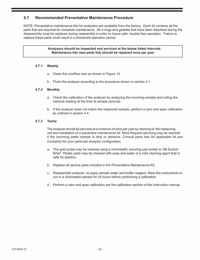
4.7 Recommended Preventative Maintenance Procedure
NOTE: Preventative maintenance kits for analyzers are available from the factory. Each kit contains all the parts that are required for complete maintenance. All o-rings and gaskets that have been disturbed during the disassembly must be replaced during reassembly in order to insure safe, trouble free operation. Failure to replace these parts could result in a shortened operation period.
Analyzers should be inspected and serviced at the below listed intervals. Maintenance kits (see parts list) should be replaced once per year.
4.7.1 Weekly
a. CleantheoverflowweirasshowninFigure14.
b. Flush the analyzer according to the procedure shown in section 4.1.
4.7.2 Monthly
a. Check the calibration of the analyzer by analyzing the incoming sample and noting the residual reading at the time of sample removal.
b. If the analyzer does not match the measured sample, perform a zero and span calibration as outlined in section 4.4.
4.7.3 Yearly
The analyzer should be serviced at a minimum of once per year by cleaning of the measuring cell and installation of a preventive maintenance kit. More frequent servicing may be required if the incoming water sample is dirty or abrasive. Consult parts lists for applicable kit part number(s)foryourparticularanalyzerconfiguration.
a. The gold probe may be cleaned using a nonmetallic scouring pad similar to 3M Scotch- Brite®. Plastic parts may be cleaned with soap and water of a mild cleaning agent that is safe for plastics.
b. Replace all service parts included in the Preventative Maintenance Kit.
c. Reassemble analyzer, re-apply sample water and buffer reagent. Allow the instruments to run in a chlorinated sample for 24 hours before performing a calibration
d. Perform a zero and span calibration per the calibration section of the instruction manual.
- 33 - 210.6020.15
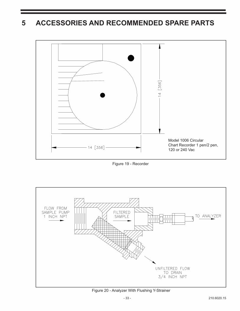
5 ACCESSORIES AND RECOMMENDED SPARE PARTS
Model 1006 Circular Chart Recorder 1 pen/2 pen, 120 or 240 Vac
Figure 19 - Recorder
Figure 20 - Analyzer With Flushing Y-Strainer
210.6020.15 - 34 -
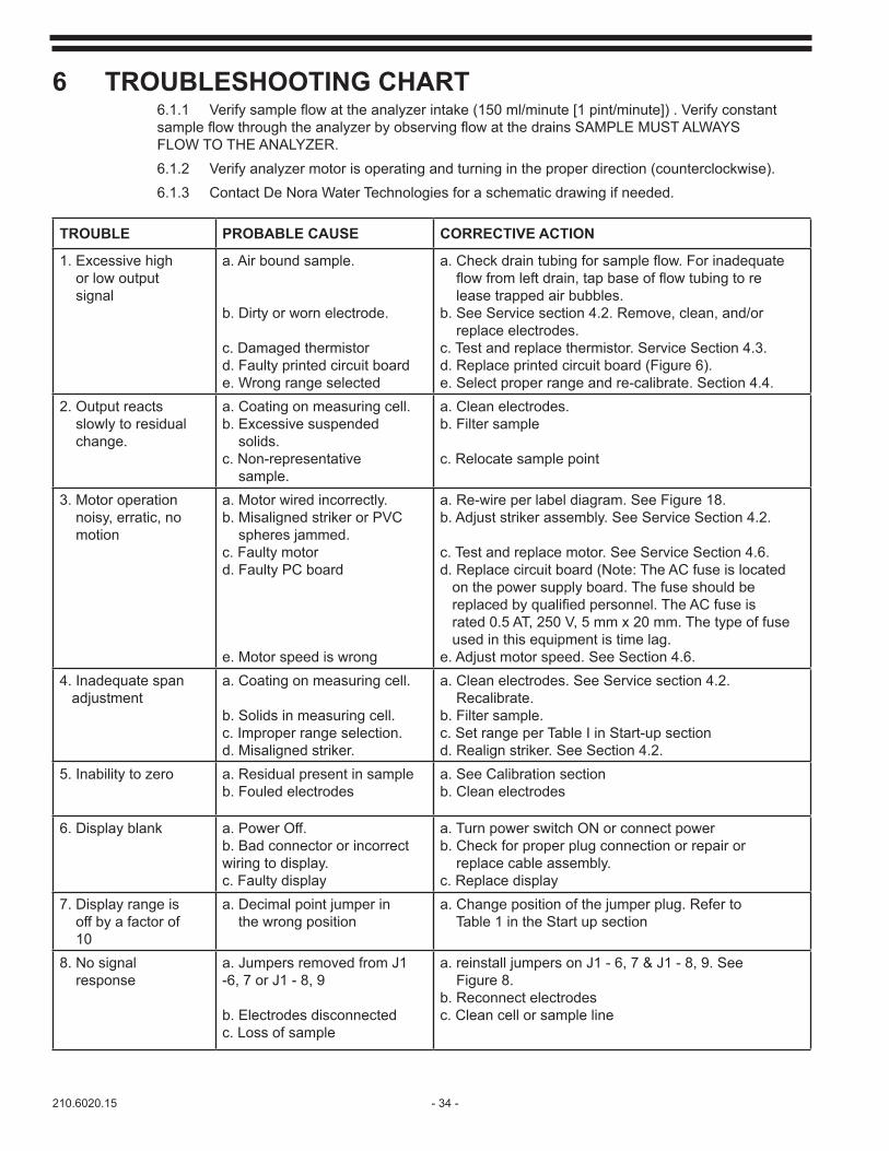
6 TROUBLESHOOTING CHART6.1.1 Verifysampleflowattheanalyzerintake(150ml/minute[1pint/minute]).VerifyconstantsampleflowthroughtheanalyzerbyobservingflowatthedrainsSAMPLEMUSTALWAYS FLOW TO THE ANALYZER.6.1.2 Verify analyzer motor is operating and turning in the proper direction (counterclockwise).6.1.3 Contact De Nora Water Technologies for a schematic drawing if needed.
TROUBLE PROBABLE CAUSE CORRECTIVE ACTION
1. Excessive high or low output signal
a. Air bound sample.
b. Dirty or worn electrode.
c. Damaged thermistord. Faulty printed circuit boarde. Wrong range selected
a.Checkdraintubingforsampleflow.Forinadequateflowfromleftdrain,tapbaseofflowtubingtore lease trapped air bubbles.b. See Service section 4.2. Remove, clean, and/or replace electrodes.c. Test and replace thermistor. Service Section 4.3.d. Replace printed circuit board (Figure 6).e. Select proper range and re-calibrate. Section 4.4.
2. Output reacts slowly to residual change.
a. Coating on measuring cell.b. Excessive suspended solids.c. Non-representative sample.
a. Clean electrodes.b. Filter sample
c. Relocate sample point
3. Motor operation noisy, erratic, no motion
a. Motor wired incorrectly.b. Misaligned striker or PVC spheres jammed.c. Faulty motord. Faulty PC board
e. Motor speed is wrong
a. Re-wire per label diagram. See Figure 18.b. Adjust striker assembly. See Service Section 4.2.
c. Test and replace motor. See Service Section 4.6.d. Replace circuit board (Note: The AC fuse is located on the power supply board. The fuse should be replacedbyqualifiedpersonnel.TheACfuseis rated 0.5 AT, 250 V, 5 mm x 20 mm. The type of fuse used in this equipment is time lag.e. Adjust motor speed. See Section 4.6.
4. Inadequate span adjustment
a. Coating on measuring cell.
b. Solids in measuring cell.c. Improper range selection.d. Misaligned striker.
a. Clean electrodes. See Service section 4.2. Recalibrate.b. Filter sample.c. Set range per Table I in Start-up sectiond. Realign striker. See Section 4.2.
5. Inability to zero a. Residual present in sampleb. Fouled electrodes
a. See Calibration sectionb. Clean electrodes
6. Display blank a. Power Off.b. Bad connector or incorrect wiring to display.c. Faulty display
a. Turn power switch ON or connect powerb. Check for proper plug connection or repair or replace cable assembly. c. Replace display
7. Display range is off by a factor of 10
a. Decimal point jumper in the wrong position
a. Change position of the jumper plug. Refer to Table 1 in the Start up section
8. No signal response
a. Jumpers removed from J1 -6, 7 or J1 - 8, 9
b. Electrodes disconnectedc. Loss of sample
a. reinstall jumpers on J1 - 6, 7 & J1 - 8, 9. See Figure 8.b. Reconnect electrodesc. Clean cell or sample line

- 35 - 210.6020.15
TROUBLE PROBABLE CAUSE CORRECTIVE ACTION
9.Motor jumps a. Spheres jammedb. Spheres worn outc. Motor turning backwards
d. Copper electrode worne. Misaligned strikerf. Motor speed too fast
a. Remove motor assembly and reintallb. Replace spheresc. Check motor wiring or turn power Off for 10 seconds and then back ON.d. Replace copper electrodee. Realign strider. See section 4.2f. Adjust speed. See section 4.6
Interfering Compound Formula +/- Maximum Concentration Comments
Manganese MnO2 2 ppm Manganese dioxide
Sulfides S-2 - unknown Reducing complexes
High Conductivity ions +/- +/- 1000 µS
Salt Water (sea) NaCl 500 ppm High and varying
Zinc Orthophosphate Zn3 (PO4)2 - unknown Corrosion inhibitor
Silicates SiO2 - unknown Sodium silicate, corrosion inhibitor
Particulates solids - Very high Suspended solids
Chromate (CrO4)-2 3 ppm Potassiium chromate, corrosion inhibitor
Copper Cu 2 ppm Copper complexes
Sulfite (SO3)-2 - present Reducing agent
Metals various +/- 3 ppm
Surfactants various unknown unknown Surface acting agent
Dissolved Oxygen O2 5 ppm 10 ppm O2=about 1 ppm as Cl2
Momochloramines* NH2Cl unknown Combined chlorine
Dichloramines* NHCl2 unknown Combined chlorine
Nitrogen Trichloride* NHCl3 unknown Combined chlorine
Organic Chloramines* varous unknown Combined chlorine
Chlorine Dioxide ClO2 present Oxidants
Potassium Permanga-nate KMnO4 present Oxidants
Bromine, Iodine and other Halogens Br2, I2 present Oxidants
Ammonia NH3 - 150 ppm Apart from reactions with Cl2
*Chloramines are suspected interferences only in very high levels and when attempting to read low levels of free chlorine.** +/- means that the result of interferences will increase the reading (+) or decrease the reading (-).
6.2 Interferences of Free Chlorine Analyzer Measurements

210.6020.15 - 36 -
THIS PAGE INTENTIONALLY LEFT BLANK

- 37 - 210.6020.15
210.6020.15 - 38 -
Represented by:Design improvements may be made without notice.
JAN/2016
De Nora Water Technologies3000 Advance Lane Colmar, PA 18915 ph +1 215 997 4000 • fax +1 215 997 4062 web: www.denora.commail: [email protected]
®Registered Trademark. © 2015. All Rights Reserved.