instruction manual 389vp - spartan controls/media/resources/rosemount analytical... · instruction...
TRANSCRIPT

Instruction Manual 389VPLIQ_MAN_ABR_389VP February 2014
Triple Junction pH/ORP SensorFor additional information, please visit our website at www.rosemountanalytical.com
WARNINGBefore removing the sensor, be absolutely certain that the process pressure is reduced to 0 psig and the process temperature is lowered to a safe level!
CAUTIONSensor/Process Application CompatibilityThe wetted sensor materials may not be compatible with process composition and operating conditions.Application compatibility is entirely the responsibility of the user.
SpecificationsSensor Type: Triple-junction 389, 389VP
Range: pH: AccuGlass 0–14* ORP: -1500 to +1500 mV
*Percent Linearity Over pH Range:
Percent Linearity Over pH Range
Option 10 Option 11
0–2 pH 94% 94%
2–12 pH 99% 97%
12–13 pH 97% 98%
13–14 pH 92% 98%
Temperature Range: 0° to 85 °C (32 ° to 185 °F) Automatic temperature compensation 0° to 85 °C (32 ° to 185 °F), Temperature compensation is not required for 389 ORP or 389VP ORP when used with 1060, 1023 or 1181 ORP
Maximum Pressure: 790 kPa [abs] (100 psig) at 65 °C (150 °F) - see Graph A
Flow Rate: up to 2 ft/sec
Materials of Construction: Tefzel, glass, ceramic and Viton; Platinum ORP electrode
Process Connections: 1 in. MNPT, 2 places
VP8 Cable: PN 24281-00
Weight/Shipping Weight: 0.45 kg/0.9 kg (1 lb/2 lb)

2
389VP Instruction ManualFebruary 2014 LIQ_MAN_ABR_389VP
Figure 1. 389VP Insertion/Submersion Sensor with VP connector (uses mating VP cable)
Figure 2. Pressure/Temperature Operating Range
ATEX DIRECTIVESpecial Conditions for safe use1. All pH/ORP sensors have a plastic enclosure which must only be cleaned with a damp cloth to avoid the danger due to a
build up of an electrostatic charge.2. All pH/ORP sensor Models are intended to be in contact with the process fluid and may not meet the 500V r.m.s. a.c.
test to earth. This must be taken into consideration at installation.

3
Instruction Manual 389VPLIQ_MAN_ABR_389VP February 2014
Storage1. It is recommended that electrodes be stored in their original shipping containers until needed.2. Do not store at temperatures below -5 °C (23 °F).3. Electrodes should be stored with a protective cap containing KCl solution (PN 9210342).4. For overnight storage, immerse the sensor in tap water or 4 pH buffer solution.5. A pH glass electrode has a limited shelf life of one year.
Electrode Preparations1. Remove electrode from shipping container.2. Remove the protective boot covering the electrode bulb.3. Rinse away salt film with clean water, then shake the electrode so that the internal solution fills the bulb, thus removing
any air trapped there.
Note
Do not allow lubricant to coat electrode bulb or reference junction. If it does, wipe it clean before installation.
InstallationFor sensor orientation, see Figure 3.
Figure 3. Sensor Orientation
Figure 4. Sensor Dimensions
For sensor dimensions, see Figure 4.
Install sensor within 80° of vertical
10° 10°
4
389VP Instruction ManualFebruary 2014 LIQ_MAN_ABR_389VP
For wiring, see Figures 6-14
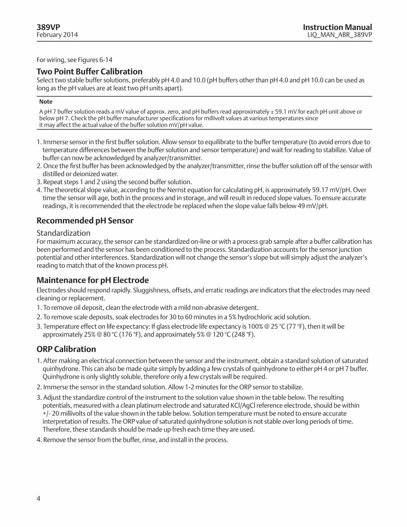
Two Point Buffer CalibrationSelect two stable buffer solutions, preferably pH 4.0 and 10.0 (pH buffers other than pH 4.0 and pH 10.0 can be used as long as the pH values are at least two pH units apart).
Note
A pH 7 buffer solution reads a mV value of approx. zero, and pH buffers read approximately ± 59.1 mV for each pH unit above or below pH 7. Check the pH buffer manufacturer specifications for millivolt values at various temperatures sinceit may affect the actual value of the buffer solution mV/pH value.
1. Immerse sensor in the first buffer solution. Allow sensor to equilibrate to the buffer temperature (to avoid errors due to temperature differences between the buffer solution and sensor temperature) and wait for reading to stabilize. Value of buffer can now be acknowledged by analyzer/transmitter.
2. Once the first buffer has been acknowledged by the analyzer/transmitter, rinse the buffer solution off of the sensor with distilled or deionized water.
3. Repeat steps 1 and 2 using the second buffer solution. 4. The theoretical slope value, according to the Nernst equation for calculating pH, is approximately 59.17 mV/pH. Over
time the sensor will age, both in the process and in storage, and will result in reduced slope values. To ensure accurate readings, it is recommended that the electrode be replaced when the slope value falls below 49 mV/pH.
Recommended pH Sensor
StandardizationFor maximum accuracy, the sensor can be standardized on-line or with a process grab sample after a buffer calibration has been performed and the sensor has been conditioned to the process. Standardization accounts for the sensor junction potential and other interferences. Standardization will not change the sensor’s slope but will simply adjust the analyzer’s reading to match that of the known process pH.
Maintenance for pH ElectrodeElectrodes should respond rapidly. Sluggishness, offsets, and erratic readings are indicators that the electrodes may need cleaning or replacement.1. To remove oil deposit, clean the electrode with a mild non-abrasive detergent.2. To remove scale deposits, soak electrodes for 30 to 60 minutes in a 5% hydrochloric acid solution.3. Temperature effect on life expectancy: If glass electrode life expectancy is 100% @ 25 °C (77 °F), then it will be
approximately 25% @ 80 °C (176 °F), and approximately 5% @ 120 °C (248 °F).
ORP Calibration1. After making an electrical connection between the sensor and the instrument, obtain a standard solution of saturated
quinhydrone. This can also be made quite simply by adding a few crystals of quinhydrone to either pH 4 or pH 7 buffer. Quinhydrone is only slightly soluble, therefore only a few crystals will be required.
2. Immerse the sensor in the standard solution. Allow 1-2 minutes for the ORP sensor to stabilize.
3. Adjust the standardize control of the instrument to the solution value shown in the table below. The resulting potentials, measured with a clean platinum electrode and saturated KCl/AgCl reference electrode, should be within +/- 20 millivolts of the value shown in the table below. Solution temperature must be noted to ensure accurate interpretation of results. The ORP value of saturated quinhydrone solution is not stable over long periods of time. Therefore, these standards should be made up fresh each time they are used.
4. Remove the sensor from the buffer, rinse, and install in the process.
5
Instruction Manual 389VPLIQ_MAN_ABR_389VP February 2014
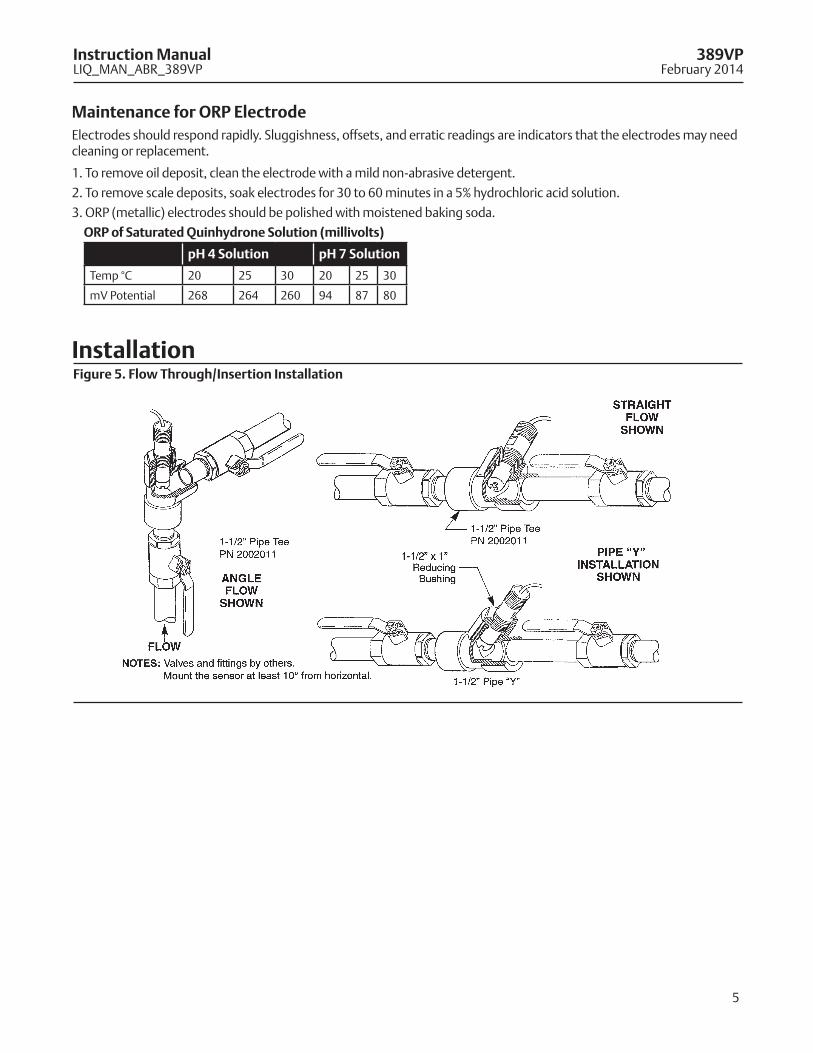
Maintenance for ORP ElectrodeElectrodes should respond rapidly. Sluggishness, offsets, and erratic readings are indicators that the electrodes may need cleaning or replacement.
1. To remove oil deposit, clean the electrode with a mild non-abrasive detergent.
2. To remove scale deposits, soak electrodes for 30 to 60 minutes in a 5% hydrochloric acid solution.
3. ORP (metallic) electrodes should be polished with moistened baking soda.
ORP of Saturated Quinhydrone Solution (millivolts)
pH 4 Solution pH 7 Solution
Temp °C 20 25 30 20 25 30
mV Potential 268 264 260 94 87 80
InstallationFigure 5. Flow Through/Insertion Installation

6
389VP Instruction ManualFebruary 2014 LIQ_MAN_ABR_389VP
WiringNote
For additional wiring information on this product, including sensor combinations not shown here, please refer to either our online wiring programs or the Manual DVD enclosed with each product.
1056, 1057, 56, 5081, 6081, 54e, and XMT : http://www3.emersonprocess.com/raihome/sp/liquid/wiring/XMT/1066 and sensors with SMART preamps: http://www2.emersonprocess.com/en-US/brands/rosemountanalytical/Liquid/Sensors/Pages/Wiring_Diagram.aspx1055: http://www3.emersonprocess.com/raihome/sp/liquid/wiring/1055/
Figure 6. pH/ORP Sensor Wiring for 1056/1057/56/389VP-70 (Blue Cable)
7
Instruction Manual 389VPLIQ_MAN_ABR_389VP February 2014
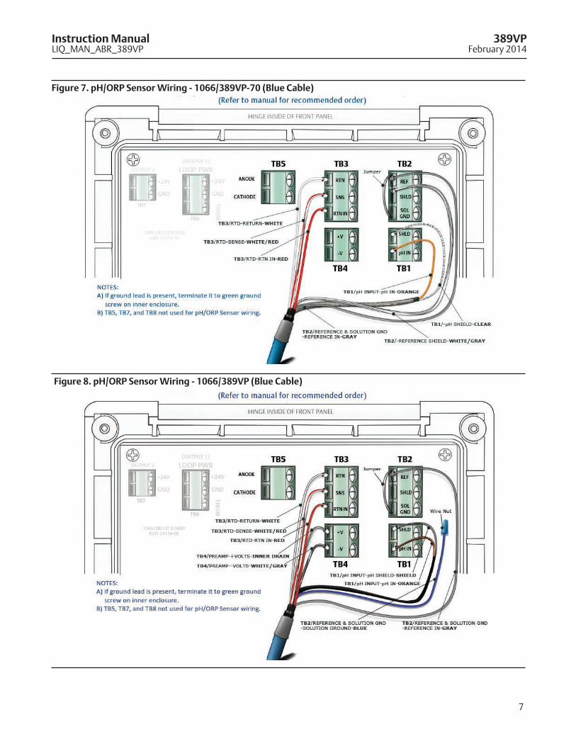
Figure 7. pH/ORP Sensor Wiring - 1066/389VP-70 (Blue Cable)
Figure 8. pH/ORP Sensor Wiring - 1066/389VP (Blue Cable)

8
389VP Instruction ManualFebruary 2014 LIQ_MAN_ABR_389VP
Figure 9. pH/ORP Sensor Wiring - 5081/389VP-70 (Blue Cable)
Figure 10. pH/ORP Sensor Wiring - 6081/389VP-70 (Blue Cable)
9
Instruction Manual 389VPLIQ_MAN_ABR_389VP February 2014
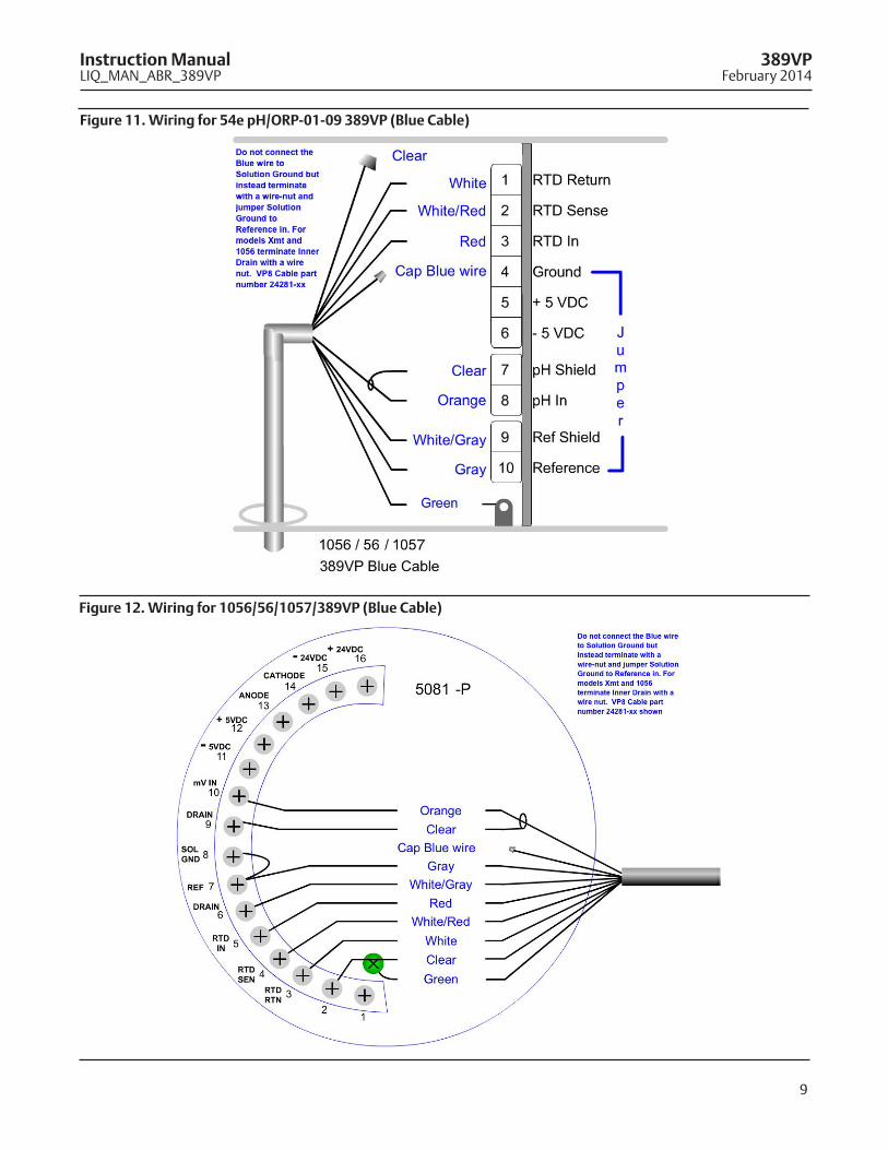
Figure 11. Wiring for 54e pH/ORP-01-09 389VP (Blue Cable)
Figure 12. Wiring for 1056/56/1057/389VP (Blue Cable)
10
389VP Instruction ManualFebruary 2014 LIQ_MAN_ABR_389VP
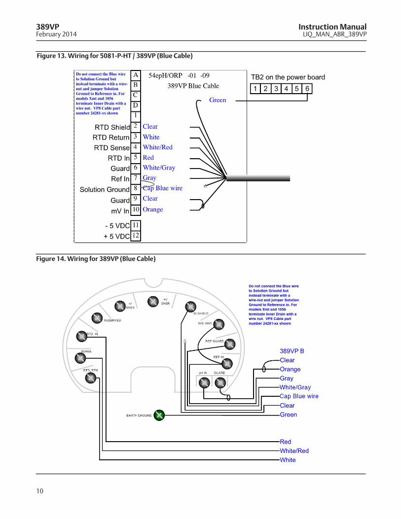
Figure 13. Wiring for 5081-P-HT / 389VP (Blue Cable)
Figure 14. Wiring for 389VP (Blue Cable)
11
Instruction Manual 389VPLIQ_MAN_ABR_389VP February 2014
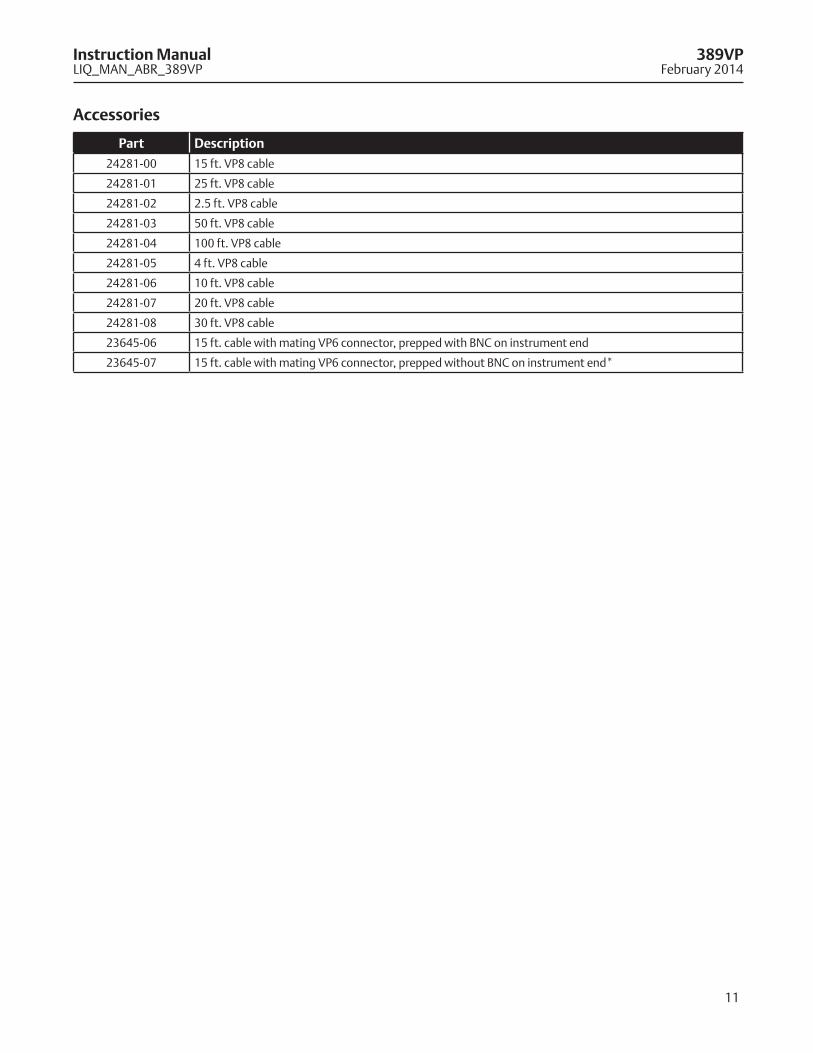
Accessories
Part Description
24281-00 15 ft. VP8 cable
24281-01 25 ft. VP8 cable
24281-02 2.5 ft. VP8 cable
24281-03 50 ft. VP8 cable
24281-04 100 ft. VP8 cable
24281-05 4 ft. VP8 cable
24281-06 10 ft. VP8 cable
24281-07 20 ft. VP8 cable
24281-08 30 ft. VP8 cable
23645-06 15 ft. cable with mating VP6 connector, prepped with BNC on instrument end
23645-07 15 ft. cable with mating VP6 connector, prepped without BNC on instrument end*

Credit Cards for U.S. Purchases Only.
8
Emerson Process Management2400 Barranca ParkwayIrvine, CA 92606 USATel: (949) 757-8500Fax: (949) 474-7250rosemountanalytical.com
© Rosemount Analytical Inc. 2014
©2014 Rosemount Analytical, Inc. All rights reserved.
The Emerson logo is a trademark and service mark of Emerson Electric Co. Brand name is a mark of one of the Emerson Process Management family of companies. All other marks are the property of their respective owners.
The contents of this publication are presented for information purposes only, and while effort has been made to ensure their accuracy, they are not to be construed as warranties or guarantees, express or implied, regarding the products or services described herein or their use or applicability. All sales are governed by our terms and conditions, which are available on request. We reserve the right to modify or improve the designs or specifications of our products at any time without notice.
facebook.com/EmersonRosemountAnalytical
AnalyticExpert.com
twitter.com/RAIhome
youtube.com/user/RosemountAnalytical
Instruction Manual 389VPLIQ_MAN_ABR_389VP February 2014
Rev. H