instruction manual - fullcompass.com · 1 for more information contact speco technologies 200 new...
TRANSCRIPT
1 For more information contact Speco Technologies
200 New Highway, Amityville, NY 11701• Toll Free: 1-800-645-5516•Fax: 631-957-9142 or 631-957-3880•www.specotech.com
INSTRUCTION
MANUAL
PBM120A - 120 WATT RMS PUBLIC
ADDRESS AMPLIFIER
PBM120AT 120 WATT RMS PUBLIC
ADDRESS AMPLIFIER WITH TUNER
PBM120AU 120 WATT RMS PUBLIC
ADDRESS AMPLIFIER WITH TUNER/CD/USB
2 For more information contact Speco Technologies
200 New Highway, Amityville, NY 11701• Toll Free: 1-800-645-5516•Fax: 631-957-9142 or 631-957-3880•www.specotech.com
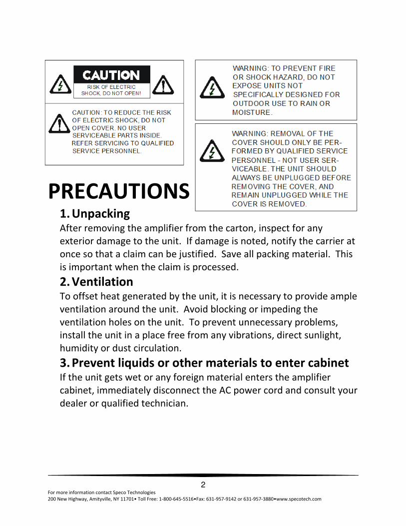
PRECAUTIONS 1. Unpacking After removing the amplifier from the carton, inspect for any
exterior damage to the unit. If damage is noted, notify the carrier at
once so that a claim can be justified. Save all packing material. This
is important when the claim is processed.
2. Ventilation To offset heat generated by the unit, it is necessary to provide ample
ventilation around the unit. Avoid blocking or impeding the
ventilation holes on the unit. To prevent unnecessary problems,
install the unit in a place free from any vibrations, direct sunlight,
humidity or dust circulation.
3. Prevent liquids or other materials to enter cabinet If the unit gets wet or any foreign material enters the amplifier
cabinet, immediately disconnect the AC power cord and consult your
dealer or qualified technician.

3 For more information contact Speco Technologies
200 New Highway, Amityville, NY 11701• Toll Free: 1-800-645-5516•Fax: 631-957-9142 or 631-957-3880•www.specotech.com
IMPORTANT SAFETY INSTRUCTIONS 1. Read these instructions completely.
2. Keep these instructions for future reference.
3. Heed all warnings.
4. Follow all instructions.
5. Do not use this apparatus near water.
6. Clean only with a dry cloth.
7. Do not block ventilation openings. Install in accordance with instructions.
8. Do not install on or near any heat sources such as radiators, heat registers,
stoves or other apparatus (including amplifiers) that produce heat.
9. Do not defeat purpose of the polarized or grounding-type plug. A polarized
plug has two blades with one wider that the other. A grounding type plug
has two blades and a third grounding prong. The wide blade and the third
prong are provided for your safety. If the provided plug does not fit into
your outlet, consult an electrician for replacement of the obsolete outlet.
10. Protect the power cord from being walked on or pinched, particularly at
plugs, convenience receptacles and where connected to the apparatus.
11. Only use the attachments/accessories specified by the manufacturer.
12. Use only with the cart, stand, tripod, bracket or table
specified by the manufacturer, or sold with the apparatus.
When a cart is used, use caution when moving the
cart/apparatus combination to avoid injury from tip-over.
13. Unplug this apparatus during lightning storms or when
unused for long periods of time.
14. Refer all servicing to qualified service personnel. Servicing is
required when the apparatus has been damaged in any way such as power
supply cord or plug is damaged, liquid has been spilled or objects have
fallen into the apparatus, the apparatus has been exposed to rain or
moisture, does not operate normally, or has been dropped.
15. Apparatus shall not be exposed to dripping or splashing and no objects
filled with liquids, such as vases, shall be placed on the apparatus.
16. WARNING – To reduce the risk of fire or electric shock, do not expose this
apparatus to rain or moisture.
17. CAUTION – Use of any controls or adjustments or performance of
procedures other than those specified herein may result in hazardous
radiation exposure.

4 For more information contact Speco Technologies
200 New Highway, Amityville, NY 11701• Toll Free: 1-800-645-5516•Fax: 631-957-9142 or 631-957-3880•www.specotech.com
Thank You! We at Speco Technologies thank you for your purchase of our PBM120A, PBM120AT or PBM120AU
amplifier. The PBM120A is the first in Speco Technologies next generation of commercial public address
amplifiers.
We have taken our customers’ input and created the perfect amplifier for almost any application. In
addition to the great features you’ve come to expect in a Speco Technologies amplifier, the new PBM-A
series has ample inputs, an included IR-remote control, an RS232 input for integration with control
systems, front panel locking capability, and includes all rack-mounting hardware.
With a stylish appearance and all these additional features at a price similar to previous generation
amplifiers, the new PBM-A series is sure to become your go-to amplifier.
Please review this checklist of components to make sure you received all items with your amplifier:
Inside the box (PBM120A)
• One amplifier
• One product manual
• One IR remote control (Battery included)
• One set of rack mounting hardware including two (2) brackets
• AC Power Cord
If you have purchased a PBM120AU or PBM120AT, the module will already be factory installed, and this
box should also include:
• AM Antenna
• FM Antenna
Please make sure you have all accessories and your box and unit did not suffer any noticeable damage
during transit prior to connecting your amplifier.
TABLE OF CONTENTS
Page 3 Safety Instructions
Page 5 Features and Specifications
Page 5 Front Panel
Page 7 Rear Panel
Page 10 Reference Information
Page 11 PBM120AU Instructions
Page 14 PBM120AT Instructions
Page 15 IR Remote
5 For more information contact Speco Technologies
200 New Highway, Amityville, NY 11701• Toll Free: 1-800-645-5516•Fax: 631-957-9142 or 631-957-3880•www.specotech.com
SECTION 1: FEATURES AND SPECIFICATIONS
• 120W RMS/240W Max Power
• AC 115V, 60Hz
• 3 XLR Microphone inputs with selectable phantom power (Mic 1 has selectable priority)
• Telephone paging input
• Music on hold output
• 5 zoned speaker outputs (70 or 25V)
• Non-zoned 4/8/16 Ohm output
• RCA or XLR line output
• Front Bass and Treble controls
• Individual volume control for each input
• Master digital volume control
• Digital front panel lock
• RS232 input for integration with popular control systems
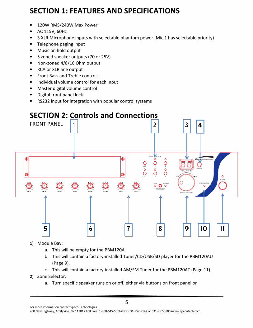
SECTION 2: Controls and Connections
FRONT PANEL
1) Module Bay:
a. This will be empty for the PBM120A.
b. This will contain a factory-installed Tuner/CD/USB/SD player for the PBM120AU
(Page 9).
c. This will contain a factory-installed AM/FM Tuner for the PBM120AT (Page 11).
2) Zone Selector:
a. Turn specific speaker runs on or off, either via buttons on front panel or

6 For more information contact Speco Technologies
200 New Highway, Amityville, NY 11701• Toll Free: 1-800-645-5516•Fax: 631-957-9142 or 631-957-3880•www.specotech.com
through IR remote control.
b. If a zone is turned on, the LED above the zone button will illuminate.
3) Volume Level Indicator:
a. This display will indicate the level of volume of the amplifier.
b. Volume can be changed either using the Master Volume Knob (#9) or by using
the IR remote control
4) IR receiver:
a. Aim your IR remote control at this window to control the amplifier.
b. Range of the IR remote can be extended by using an optional IR repeater, such
as the Speco Technologies Part Number IRRPTKIT.
5) Microphone Volume Control Knobs:
a. Turn the knob left to decrease the microphone volume relative to other inputs.
b. Turn the knob right to increase the microphone volume relative to other inputs.
6) Auxiliary Input Volume Control Knobs:
a. Turn the knob left to decrease the AUX input volume relative to other inputs.
b. Turn the knob right to increase the AUX input volume relative to other inputs.
7) Tone Controls:
a. Turning the Bass knob left or right will increase or decrease the bass of all inputs.
b. Turning the Treble knob left or right will increase or decrease the treble of all inputs.
8) Source Select Button:
a. Pushing this button will alternate between the auxiliary inputs and then module
input as the main source.
b. If a module is not installed (PBM120A), no audio will play if module is selected.
9) Master Volume Knob:
a. Turn the knob to the left to decrease the volume of all inputs and sources.
b. Turn the knob to the right to increase the volume of all inputs and sources.
10) System Lock Indicator:
a. This amplifier comes complete with a feature that will lock the functions of the front
panel so that only the IR remote can control the amplifier.
b. This is useful for when the amplifier is installed in a public area and unauthorized
personnel or customers might have access to the volume, source, etc.
11) Standby Power Button:
a. This button will enable the amplifier to enter and exit standby mode.
b. When in standby mode, the LED light above the button will illuminate.

7 For more information contact Speco Technologies
200 New Highway, Amityville, NY 11701• Toll Free: 1-800-645-5516•Fax: 631-957-9142 or 631-957-3880•www.specotech.com
Section 2: Controls and Connections REAR PANEL
12) Main Power Switch:
a. This switch will completely turn the amplifier power on and off.
13) Commercial Speaker Zone Outputs:
a. This amplifier comes complete with both constant voltage and constant
impedance outputs. Only one type of output may be used at a time.
Attempting to use both simultaneously could damage the amplifier and/or
speakers and would void the warranty.
b. 5 outputs are provided to make speaker wiring easier and to allow for
distribution of speakers into groups.
c. In conjunction with the buttons on the front panel (#2), audio can be turned on
and off to these zones.
VERY IMPORTANT: Make sure commercial audio principles are followed and the proper
speaker types are wired to the proper outputs. Putting the incorrect speakers on the
incorrect output can damage your speakers and/or amplifier and is not covered under
warranty. If unsure, please contact a professional.
14) RS232 Connector:
a. This connection allows the amplifier to be controlled by a remote source, such
as a third party automation system.
b. Programming instructions are available upon request. Please contact the Speco
Technologies Technical Support department.
PLEASE NOTE: For Music-on-hold and Telephone Paging, please refer to the instructions
of your PBX or telephone paging system for proper function. These are simply passive
inputs that allow for either music to be fed into the phone system for audio while callers

8 For more information contact Speco Technologies
200 New Highway, Amityville, NY 11701• Toll Free: 1-800-645-5516•Fax: 631-957-9142 or 631-957-3880•www.specotech.com
are on hold, or for using the features of the phone system to send a page via a specific
output on the phone system. Installation instructions vary widely by manufacturer. If
unsure, please contact a professional.
15) Music-on-hold (MOH) Volume Knob:
a. This knob will allow you to adjust the volume of the MOH output.
16) Music-on-hold (MOH) Output:
a. These terminals allow output of the amplifier’s audio to another source, such as
a telephone paging system.
i. 600 Ohms/1V
ii. 8 Ohms/1W
17) Telephone Paging Inputs:
a. These inputs will allow you to utilize your amplifier with a telephone paging system
for purposes of paging.
18) Telephone Paging Volume Knob:
a. If connected to a phone system, this will allow adjustment of the incoming audio.
19) AM Antenna Input:
a. This terminal will allow you to connect an AM antenna for your module.
b. The antenna will only be included with a PBM120AT and PBM120AU.
20) AC Power Inlet:
a. Connect your included power cord here, carefully following all safety instructions.
21) External Fuse:
a. T10AL, 250V fuse can be replaced here.
22) Zone Output Switch:
a. Change the format of the zoned commercial outputs between 25V and 70V.
VERY IMPORTANT: NEVER switch output while amplifier is active. NEVER switch output and
power amplifier if incorrect speakers are connected to the output. Damage can occur to the
amplifier and/or speakers and the warranty will be void. If unsure, please consult a
professional.
23) Single-Zone Constant Impedance Outputs
a. This amplifier comes complete with both constant voltage and constant impedance
outputs. Only one type of output may be used at a time. Attempting to use both
simultaneously could damage the amplifier and/or speakers and would void the
warranty.
b. This amplifier offers single-channel 4 Ohm, 8 Ohm and 16 Ohm outputs
24) XLR Line Output:
a. Utilize this XLR output to connect the amplifier to a booster amplifier with a
matching input
25) RCA Line Output:
a. Utilize this RCA output to connect the amplifier to another amplifier with RCA inputs

9 For more information contact Speco Technologies
200 New Highway, Amityville, NY 11701• Toll Free: 1-800-645-5516•Fax: 631-957-9142 or 631-957-3880•www.specotech.com
to daisy chain amplifiers.
26) Auxiliary Inputs:
a. These inputs accept right and left channel RCA inputs.
27) Phantom Power Switch:
a. This amplifier provides phantom power to the appropriate microphones.
b. This switch will turn the phantom power feature on and off for each microphone
input.
28) Microphone Inputs:
a. This amplifier has three XLR microphone inputs.
b. To expand the number of microphone inputs on this amp, we suggest using an
external microphone mixer such as Speco Technologies’ Part numbers MMB3XLR (3
input) or MMB8XLRLL (8 input) and connecting that mixer to one of the three XLR
microphone inputs.
29) Priority Paging Switch
a. Activation of this switch will allow any microphone connected to MIC1 to take
priority.
b. This means that when a page is made from a microphone connected to this input, all
other audio sources will be temporarily muted.
30) FM Antenna Input:
a. This terminal will allow you to connect an FM antenna for your module.
b. The antenna will only be included with a PBM120AT and PBM120AU.

10 For more information contact Speco Technologies
200 New Highway, Amityville, NY 11701• Toll Free: 1-800-645-5516•Fax: 631-957-9142 or 631-957-3880•www.specotech.com
SECTION 3: REFERENCE INFORMATION
The following information is provided for reference only. Please consult a professional if
unsure about any aspects of commercial or residential installations.
SPEAKER CONNECTION
The rear panel of the amplifier contains 5, zoned speaker connections.
BE SURE TO CONNECT SPEAKERS PROPERLY, see line voltage instructions below.
The speaker lines are to be connected directly between the appropriate COM terminal on the
terminal strip and the terminal corresponding to the impedance of the speaker(s).
Connect the cables to the terminals on the screw terminal strip provided. Use the screw
terminals which correspond to the proper polarity of the speaker(s). One lead must always be
connected to the COM.
IMPORTANT NOTICE: When 70V or 25V constant line voltages are used, a line matching
transformer must be used with each speaker. All transformers must be connected in parallel.
ALWAYS CONNECT LINE TRANSFORMERS IN PARALLEL, NEVER CONNECT IN SERIES
SPEAKER IMPEDANCES
Speaker terminal taps for 70V constant line voltage are provided on the rear panel of the unit.
To connect the power output directly to a speaker or PA horn or a combination of speakers
and/or PA horns, connect to the COM and (+) terminal on the strip. Be sure the speaker(s) or PA
horn(s) can handle a reasonable power output from the amplifier or permanent damage to the
speaker(s) or PA horn(s) may result. Also, be careful not to overload the amplifier with too
many speakers or PA horns. If it is desired to use a number and variety of speakers, the
speakers must be arranged in various series or parallel arrays to provide proper impedance
matching. 70V constant line voltage must be used (parallel connection only). If you are not
familiar with impedance matching, consult a professional installer or technician for advice. If
70V constant line voltages are used, a line matching transformer must be used with each
speaker. Again do not overload or use incompatible speakers. Line transformers are the
preferred method for multi-speaker installation.
CABLE REQUIREMENTS
Output cabling need not be shielded in most cases and should be of sufficient gauge to minimize
losses due to the resistance of the wire over long runs (insertion loss). Cable thinner than 18
gauge AWG is not recommended. Long runs require 16 gauge AWG or heavier.
In some cases where the output cable is run in close proximity to unshielded intercom cables,
electrical cables, radio transmission antennas or other sources of interference, or when the
amplifier is being used for paging from a telephone system, the amplifier may require shielded
output cabling to prevent audio feedback or interference.
PRIORITY PAGE
The amplifier features a voice activated priority page circuit and automatically mutes all
program material (Auxiliary, Module, Microphone, etc.) from the amplifier’s output, and
permits MIC 1 and the TEL input to override for paging announcements.

11 For more information contact Speco Technologies
200 New Highway, Amityville, NY 11701• Toll Free: 1-800-645-5516•Fax: 631-957-9142 or 631-957-3880•www.specotech.com
TELEPHONE LINE
A telephone line input of 600 Ohms is provided. For phone systems with this feature, a Music
on Hold output is also available.
WHENEVER IN DOUBT ABOUT INSTALLATION, CONSULT WITH A PROFESSIONAL INSTALLER
OR TECHNICIAN. OTHERWISE, PERSONAL INJURY, DAMAGE TO THIS AMPLIFIER
AND/OR SPEAKERS MAY RESULT AND YOUR WARRANTY MAY BE VOID.
SECTION 4: OPTIONAL MODULES PBM120AU
This amplifier comes complete with a Anti-Shock CD/USB/SD/Tuner module installed. The
function is identical to the PBM120A, except for that the input select button on the front must
be changed to “Module” for the installed module to properly function.
HARDWARE:
This unit accepts SD/SDHC Card readers, USB Thumb Drives and standard disks, such as CD, CD-
R, CD-RW, and MP3 disk. Do not insert a mini-disk. In addition to standard analog CD tracks, this
unit can play MP3 and WMA formats.
CD Operation:
When inserting or removing a disk in the CD player, you must let the automatic system
complete its insertion or ejection process. It is prohibited to push or take out the disk by hand
before the disk is completely in/out from the device, otherwise it will damage the unit.
USB Operation:
• Insert a USB thumb drive in the faceplate.
• Press CD / USB / SD / Radio button on the remote controller or faceplate to select USB
mode. USB function will activate when “USB” appears on the LCD display.
SD / SDHC Card Operation:
• Insert SD / SDHC Card into SD hole in the front panel. Push the card in so that it catches
properly in the device.
• Press CD / USB / SD / Radio button on the remote controller or faceplate to select SD mode.
SD function will activate when “SD” appears on the LCD display.
SYSTEM CONTROLS:
• VOLUME: For mixing volume relative to other inputs on the amplifier.
CD / USB / SD READER OPERATION:
• PLAY / II: Press to start and pause play of the source
12 For more information contact Speco Technologies
200 New Highway, Amityville, NY 11701• Toll Free: 1-800-645-5516•Fax: 631-957-9142 or 631-957-3880•www.specotech.com
• STOP/ EJECT: Will stop playing while source is active, or will eject CD if pressed when CD is
inserted and no source is playing
o Press to stop and the LCD display will show the total number of tracks.
o Press again to eject the disk; LCD display will show: “EJECT”
o If pressed again while CD has not been removed, the disk will be automatically
reinserted.
• CD / USB / SD / RADIO: Press the button to select the function of CD, USB, SD Card, or
RADIO mode.
• RAN / ENTER:
o Press to play all songs in a random order. The LCD display shows “RANDOM”
o Press again, LCD display shows “Enter” to confirm the “PROG” function.
(Please see “PROG” section for operating program function.)
• REPEAT : Repeat play
o If a CD is the active source playing analog tracks:
1. Press once to constantly repeat current track. The LCD display shows “REPEAT
1”.
2. Press again to constantly repeat whole CD. The LCD display shows “REPEAT ALL”
3. Press again to cancel repeat function
o If a CD, USB, or SD Card is the active source playing MP3 tracks:
1. Press to constantly repeat current track. LCD display shows “REPEAT”
2. Press again to constantly repeat current folder. LCD display shows ”REPEAT
FOLDER”
3. Then press again to repeat whole songs in the file. LCD display shows “REPEAT
ALL”
4. Press once again to cancel the REPEAT function.
• FOLDER ��: Forward to next folder
• FOLDER �� : Return to last folder
• REV :
o Press once to rewind to previous track
o Press for 5 seconds to rewind through current track
• FWD:
o Press once to forward to next track
o Press for 5 seconds to fast forward the current track
• MUTE: Press to temporarily mute the module source.
• PROG: Press to set presets.
o To create a program of standard analog tracks from a CD:
1. Press “PROG” and the LCD display will show “PROGRAM”
2. Select desired song by using SKIP button, then press RAN/ENTER button once to
confirm. LCD display shows “00 01” for the first song
3. SKIP to the next song, and press RAN/ENTER twice to program as the 2nd song;
LCD display shows “00 02”
4. Repeat process for more songs (Maximum of 10)
5. Press PLAY/II to start playing programmed songs
o To program digital MP3 tracks from a CD, USB, or SD Card :
1. Press “PROG”, LCD display shows “PROGRAM”

13 For more information contact Speco Technologies
200 New Highway, Amityville, NY 11701• Toll Free: 1-800-645-5516•Fax: 631-957-9142 or 631-957-3880•www.specotech.com
2. Select desired songs by using FOLDER and SKIP button, then press RAN / ENTER
button once to confirm. LCD display shows “00 01” for the first song
3. SKIP to the next song, and press RAN/ENTER twice to program as the 2nd song;
LCD display shows “00 02”
4. Repeat process for more songs (Maximum of 10)
5. Press PLAY / II to start playing programmed songs
o Press PROG again to cancel the program function
RADIO OPERATION:
• Press “CD / USB / SD / RADIO” button and select Radio mode
• BAND : For switching between AM and FM bands
• TUN ▲ / TUN ▼: Press “▲” or ” ▼” to search station. Hold down for 3 seconds to
automatically scan stations. Scanning will stop when the unit reaches a station with good
reception
• M1-M5 & M+5 buttons: These buttons are used to store stations in memory as presets. Up
to 20 stations can be stored: 10 AM and 10 FM
• Press TUN ▲ / TUN ▼ button reach the desired station. Hold your choice of the M1
through M5 buttons for 3 seconds to store that station at that preset. To store in presets 6
through 10, press the M+5 button; LCD will show “M+5”, and then press your choice of the
M1 through M5 buttons for 3 seconds. Once the module has accepted the preset, the LCD
will flash CH#, with # being the number of the preset you selected.
• To play a stored station, press the M1 through M5 button, or M+5 and then M1 through
M5.
Note: Your status from each mode will be saved if you leave and return. For example, if you
switch from radio mode to the CD and then return to the radio later, the module will resume
from the last station. If you switch to another mode, the module will resume from the last song.

14 For more information contact Speco Technologies
200 New Highway, Amityville, NY 11701• Toll Free: 1-800-645-5516•Fax: 631-957-9142 or 631-957-3880•www.specotech.com
SECTION 5: OPTIONAL MODULES PBM120AT
SYSTEM CONTROLS
• VOLUME: Turn to adjust the volume up or down relative to other inputs
RADIO OPERATION
• Press " BAND” to select AM / FM.
• TUNING : Press to search radio stations. Press once to increase frequency by steps.
Holding for over 2 seconds will begin a scan and automatically stop at the next channel.
• TUNING : Press to search radio stations. Press once to decrease frequency by steps.
Holding for over 2 seconds will begin a scan and automatically stop at the previous channel.
MEMORY FUNCTION
• Up to 20 stations can be stored in memory (10 FM and 10 AM)
• Memory instructions:
o Tune your radio to the station you wish to store and press the “MEMORY“ button.
o Press either “MEM. UP” to scroll through the memory channels, or press and hold
the M1 to M5 channel you wish to store the station in.
o If you wish to store the station in M6 through M10, press +5 and then M1 through
M5 to access that slot.
o Once you’ve reached the desired slot, press Memory again to confirm your
selection.
• If a station is stored in memory, press M1 through M5, or +5 and then M1 through M5 to
access that station.

15 For more information contact Speco Technologies
200 New Highway, Amityville, NY 11701• Toll Free: 1-800-645-5516•Fax: 631-957-9142 or 631-957-3880•www.specotech.com
SECTION 6: IR REMOTE CONTROL There is an IR Remote control included with every PBM-A series amplifier.

16 For more information contact Speco Technologies
200 New Highway, Amityville, NY 11701• Toll Free: 1-800-645-5516•Fax: 631-957-9142 or 631-957-3880•www.specotech.com
Speco Technologies is constantly developing and improving products.
We reserve the right to modify product design and specifications without notice and without incurring any obligation. Rev. 7/1/12