instruction level parallelism - limits and alternatives
TRANSCRIPT
Advanced Computer Architecture Chapter 5.1
332Advanced Computer Architecture
Chapter 6
Instruction Level Parallelism - static instruction scheduling, software
pipelining, VLIW, EPIC, and multi-threadingFebruary 2018
Paul H J Kelly
These lecture notes are partly based on the course text, Hennessy and Patterson’s Computer Architecture, a quantitative approach (3rd and
4th eds), and on the lecture slides of David Patterson and John Kubiatowicz’s Berkeley course

Advanced Computer Architecture Chapter 5.2
OverviewUp to now: Dynamic scheduling, out-of-order (o-o-o): binary compatible, exploiting ILP in hardware: BTB, ROB, Reservation Stations, ...
How far can you take it?
How much of all this complexity can you shift into the compiler?
What if you can also change instruction set architecture?
VLIW (Very Long Instruction Word)
EPIC (Explicitly Parallel Instruction Computer)Intel’s (and HP’s) multi-billion dollar gamble for the future of computer architecture: Itanium, IA-64
Started ca.1994…not dead yet – but has it turned a profit?
Beyond instruction-level parallelism…
Advanced Computer Architecture Chapter 5.13
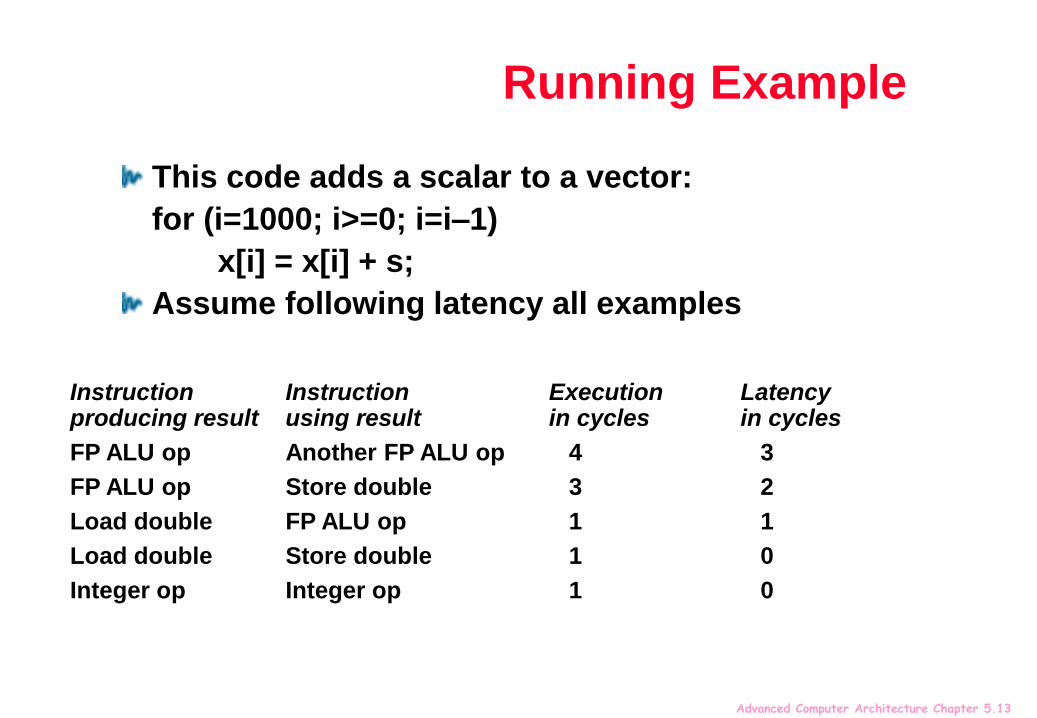
Running Example
This code adds a scalar to a vector:
for (i=1000; i>=0; i=i–1)
x[i] = x[i] + s;
Assume following latency all examples
Instruction Instruction Execution Latency producing result using result in cycles in cycles
FP ALU op Another FP ALU op 4 3
FP ALU op Store double 3 2
Load double FP ALU op 1 1
Load double Store double 1 0
Integer op Integer op 1 0
Advanced Computer Architecture Chapter 5.14
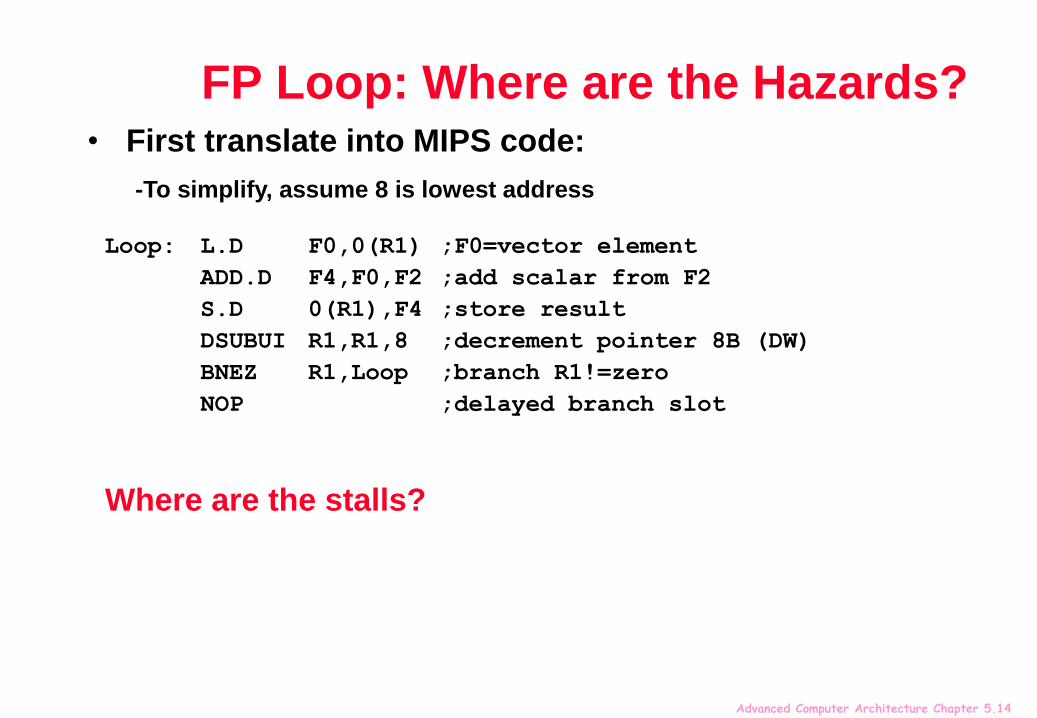
FP Loop: Where are the Hazards?
Loop: L.D F0,0(R1) ;F0=vector element
ADD.D F4,F0,F2 ;add scalar from F2
S.D 0(R1),F4 ;store result
DSUBUI R1,R1,8 ;decrement pointer 8B (DW)
BNEZ R1,Loop ;branch R1!=zero
NOP ;delayed branch slot
Where are the stalls?
• First translate into MIPS code:
-To simplify, assume 8 is lowest address

Advanced Computer Architecture Chapter 5.15
FP Loop Showing Stalls
9 clocks: Rewrite code to minimize stalls?
Instruction Instruction Latency inproducing result using result clock cycles
FP ALU op Another FP ALU op 3
FP ALU op Store double 2
Load double FP ALU op 1
1 Loop: L.D F0,0(R1) ;F0=vector element
2 stall
3 ADD.D F4,F0,F2 ;add scalar in F2
4 stall
5 stall
6 S.D 0(R1),F4 ;store result
7 DSUBUI R1,R1,8 ;decrement pointer 8B (DW)
8 BNEZ R1,Loop ;branch R1!=zero
9 stall ;delayed branch slot

Advanced Computer Architecture Chapter 5.16
Revised FP Loop Minimizing Stalls
6 clocks, but just 3 for execution, 3 for loop overhead; How make faster?
Instruction Instruction Latency inproducing result using result clock cycles
FP ALU op Another FP ALU op 3
FP ALU op Store double 2
Load double FP ALU op 1
1 Loop: L.D F0,0(R1)
2 stall
3 ADD.D F4,F0,F2
4 DSUBUI R1,R1,8
5 BNEZ R1,Loop ;delayed branch
6 S.D 8(R1),F4 ;altered when move past DSUBUI
Swap BNEZ and S.D by changing address of S.D
Advanced Computer Architecture Chapter 5.17
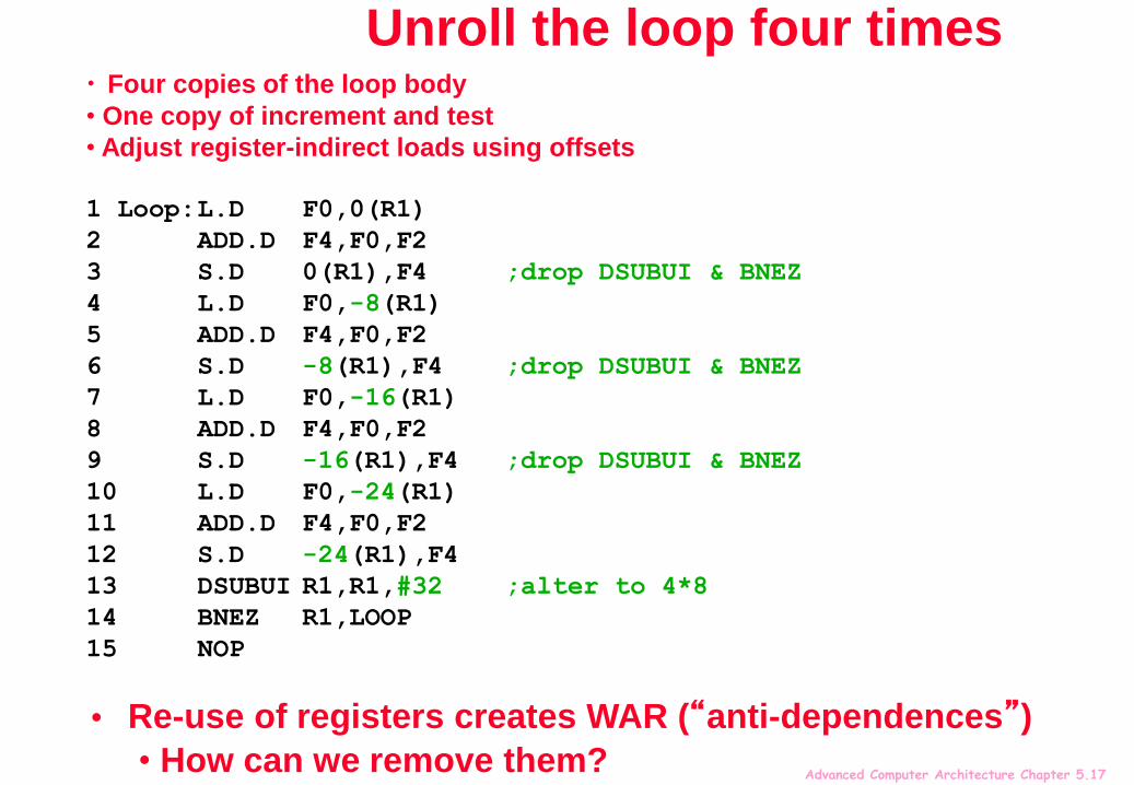
Unroll the loop four times• Four copies of the loop body
• One copy of increment and test
• Adjust register-indirect loads using offsets
1 Loop:L.D F0,0(R1)
2 ADD.D F4,F0,F2
3 S.D 0(R1),F4 ;drop DSUBUI & BNEZ
4 L.D F0,-8(R1)
5 ADD.D F4,F0,F2
6 S.D -8(R1),F4 ;drop DSUBUI & BNEZ
7 L.D F0,-16(R1)
8 ADD.D F4,F0,F2
9 S.D -16(R1),F4 ;drop DSUBUI & BNEZ
10 L.D F0,-24(R1)
11 ADD.D F4,F0,F2
12 S.D -24(R1),F4
13 DSUBUI R1,R1,#32 ;alter to 4*8
14 BNEZ R1,LOOP
15 NOP
• Re-use of registers creates WAR (“anti-dependences”)
• How can we remove them?

Advanced Computer Architecture Chapter 5.18
Loop unrolling…
1 Loop:L.D F0,0(R1)
2 ADD.D F4,F0,F2
3 S.D 0(R1),F4 ;drop DSUBUI & BNEZ
4 L.D F6,-8(R1)
5 ADD.D F8,F6,F2
6 S.D -8(R1),F8 ;drop DSUBUI & BNEZ
7 L.D F10,-16(R1)
8 ADD.D F12,F10,F2
9 S.D -16(R1),F12 ;drop DSUBUI & BNEZ
10 L.D F14,-24(R1)
11 ADD.D F16,F14,F2
12 S.D -24(R1),F16
13 DSUBUI R1,R1,#32 ;alter to 4*8
14 BNEZ R1,LOOP
15 NOP
The original “register renaming”

Advanced Computer Architecture Chapter 5.19
Unrolled Loop That Minimizes Stalls
What assumptions made when moved code?
OK to move store past DSUBUI even though changes register
OK to move loads before stores: get right data?
When is it safe for compiler to do such changes?
1 Loop:L.D F0,0(R1)
2 L.D F6,-8(R1)
3 L.D F10,-16(R1)
4 L.D F14,-24(R1)
5 ADD.D F4,F0,F2
6 ADD.D F8,F6,F2
7 ADD.D F12,F10,F2
8 ADD.D F16,F14,F2
9 S.D 0(R1),F4
10 S.D -8(R1),F8
11 S.D -16(R1),F12
12 DSUBUI R1,R1,#32
13 BNEZ R1,LOOP
14 S.D 8(R1),F16 ; 8-32 = -24
14 clock cycles, or 3.5 per iteration

Advanced Computer Architecture Chapter 5.20
Compare: without scheduling
1 Loop:L.D F0,0(R1)
2 ADD.D F4,F0,F2
3 S.D 0(R1),F4 ;drop DSUBUI & BNEZ
4 L.D F6,-8(R1)
5 ADD.D F8,F6,F2
6 S.D -8(R1),F8 ;drop DSUBUI & BNEZ
7 L.D F10,-16(R1)
8 ADD.D F12,F10,F2
9 S.D -16(R1),F12 ;drop DSUBUI & BNEZ
10 L.D F14,-24(R1)
11 ADD.D F16,F14,F2
12 S.D -24(R1),F16
13 DSUBUI R1,R1,#32 ;alter to 4*8
14 BNEZ R1,LOOP
15 NOP
15 + 4 x (1+2) = 27 clock cycles, or 6.8 per iterationAssumes R1 is multiple of 4
1 cycle stall
2 cycles stall
(use a fresh set of
registers for each
iteration to avoid
WAR hazards/anti-
dependences)

Advanced Computer Architecture Chapter 5.23
Static overlapping of loop bodies:“Software Pipelining”
Observation: if iterations from loops are independent, then can get more ILP by taking instructions from differentiterations
Software pipelining: reorganizes loops so that each iteration is made from instructions chosen from different iterations of the original loop (~ Tomasulo in software)
Iteration 0 Iteration
1 Iteration 2 Iteration
3 Iteration 4
Software- pipelined iteration
Advanced Computer Architecture Chapter 5.24
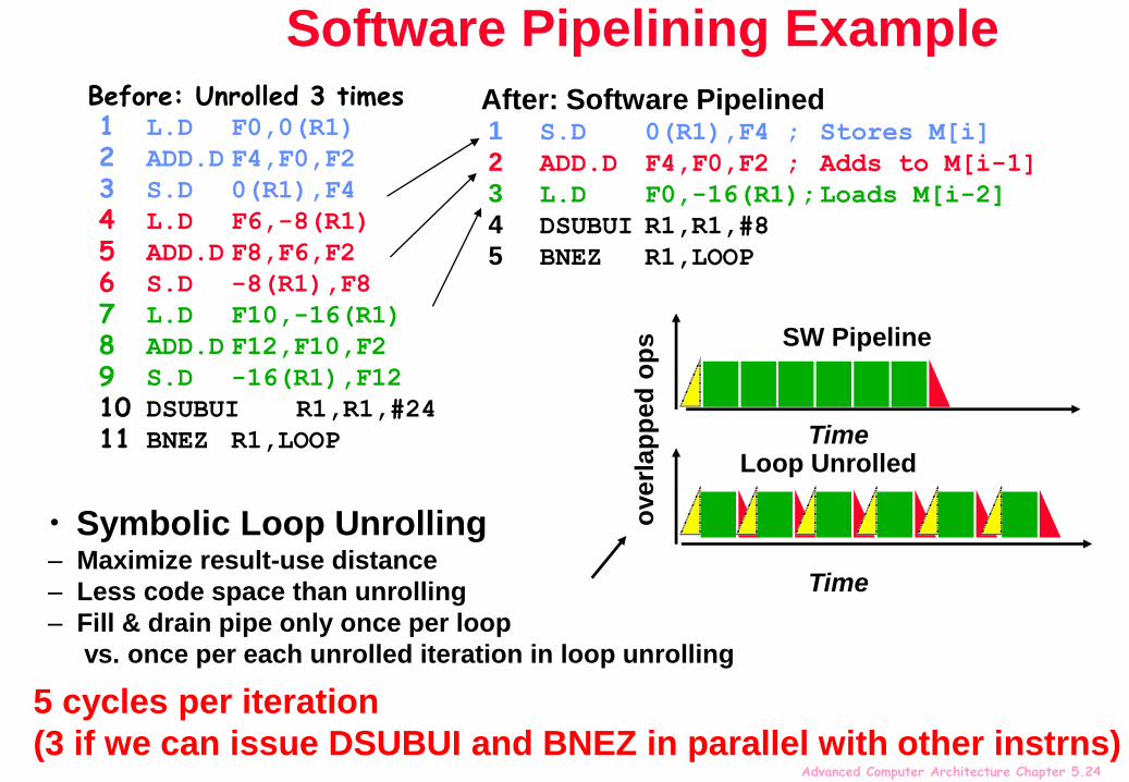
Software Pipelining ExampleBefore: Unrolled 3 times1 L.D F0,0(R1)
2 ADD.D F4,F0,F2
3 S.D 0(R1),F4
4 L.D F6,-8(R1)
5 ADD.D F8,F6,F2
6 S.D -8(R1),F8
7 L.D F10,-16(R1)
8 ADD.D F12,F10,F2
9 S.D -16(R1),F12
10 DSUBUI R1,R1,#24
11 BNEZ R1,LOOP
After: Software Pipelined1 S.D 0(R1),F4 ; Stores M[i]
2 ADD.D F4,F0,F2 ; Adds to M[i-1]
3 L.D F0,-16(R1);Loads M[i-2]
4 DSUBUI R1,R1,#8
5 BNEZ R1,LOOP
• Symbolic Loop Unrolling– Maximize result-use distance
– Less code space than unrolling
– Fill & drain pipe only once per loop
vs. once per each unrolled iteration in loop unrolling
SW Pipeline
Loop Unrolled
overl
ap
ped
op
s
Time
Time
5 cycles per iteration
(3 if we can issue DSUBUI and BNEZ in parallel with other instrns)

Advanced Computer Architecture Chapter 5.25
L.D ADD.D S.D
L.D ADD.D S.D
L.D ADD.D S.D
L.D ADD.D S.D
L.D ADD.D S.D
L.D ADD.D S.D
1 2 3 4 5 6 7 8
Pipeline fills Pipeline full Pipeline drains

Advanced Computer Architecture Chapter 5.28
What if We Can Change the Instruction Set?
Superscalar processors decide on the fly how many instructions to issue in each clock cycle
Have to check for dependences between all n pairs of instructions in a potential parallel issue packet
Hardware complexity of figuring out the number of instructions to issue is O(n2)
Entirely doable for smallish n, but tends to lead to multiple pipeline stages between fetch and issue
Why not allow compiler to schedule instruction level parallelism explicitly?
Format the instructions into a potential issue packet so that hardware need not check explicitly for dependences

Advanced Computer Architecture Chapter 5.29
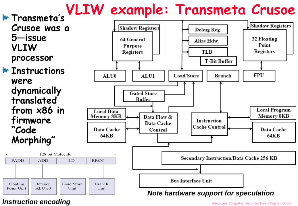
VLIW: Very Large Instruction WordEach “instruction” has explicit coding for multiple operations
In IA-64, grouping called a “packet”
In Transmeta, grouping called a “molecule” (with “atoms” as ops)
htt
p://
www.c
s.uiuc
.edu/
hom
es/
luddy/P
ROCESSORS/T
rans
meta
Cru
soe.p
df
htt
p://
www.c
s.uiuc
.edu/
hom
es/
luddy/P
ROCESSORS/T
MS320C64x.p
df
Transmeta’s Crusoe
Texas Instruments TMS320C64x
All the operations the compiler puts in the long instruction word are independent, so can be issued and can execute in parallel
E.g., 2 integer operations, 2 FP ops, 2 Memory refs, 1 branch
16 to 24 bits per field => 7*16 or 112 bits to 7*24 or 168 bits wide
Need compiling technique that schedules across several branches
Advanced Computer Architecture Chapter 5.30
VLIW example: Transmeta Crusoe
Instruction encoding
Transmeta’s Crusoe was a 5—issue VLIW processor
Instructions were dynamically translated from x86 in firmware “Code Morphing”
Note hardware support for speculation

Advanced Computer Architecture Chapter 5.31
Recall: Unrolled Loop that Minimizes Stalls for Scalar
1 Loop: L.D F0,0(R1)
2 L.D F6,-8(R1)
3 L.D F10,-16(R1)
4 L.D F14,-24(R1)
5 ADD.D F4,F0,F2
6 ADD.D F8,F6,F2
7 ADD.D F12,F10,F2
8 ADD.D F16,F14,F2
9 S.D 0(R1),F4
10 S.D -8(R1),F8
11 S.D -16(R1),F12
12 DSUBUI R1,R1,#32
13 BNEZ R1,LOOP
14 S.D 8(R1),F16 ; 8-32 = -24
14 clock cycles, or 3.5 per iteration
L.D to ADD.D: 1 Cycle
ADD.D to S.D: 2 Cycles

Advanced Computer Architecture Chapter 5.32
Loop Unrolling in VLIW
Memory Memory FP FP Int. op/ Clockreference 1 reference 2 operation 1 op. 2 branch
L.D F0,0(R1) L.D F6,-8(R1) 1
L.D F10,-16(R1) L.D F14,-24(R1) 2
L.D F18,-32(R1) L.D F22,-40(R1) ADD.D F4,F0,F2 ADD.D F8,F6,F2 3
L.D F26,-48(R1) ADD.D F12,F10,F2 ADD.D F16,F14,F2 4
ADD.D F20,F18,F2 ADD.D F24,F22,F2 5
S.D 0(R1),F4 S.D -8(R1),F8 ADD.D F28,F26,F2 6
S.D -16(R1),F12 S.D -24(R1),F16 7
S.D -32(R1),F20 S.D -40(R1),F24 DSUBUI R1,R1,#48 8
S.D -0(R1),F28 BNEZ R1,LOOP 9
Unrolled 7 times to avoid delays
7 results in 9 clocks, or 1.3 clocks per iteration (1.8X)
Average: 2.5 ops per clock, 50% efficiency
Note: Need more registers in VLIW (15 vs. 6 in SS)

Advanced Computer Architecture Chapter 5.33
Software Pipelining
Observation: if iterations from loops are independent, then can get more ILP by taking instructions from differentiterations
Software pipelining: reorganizes loops so that each iteration is made from instructions chosen from different iterations of the original loop (~ Tomasulo in SW)
Iteration 0 Iteration
1 Iteration 2 Iteration
3 Iteration 4
Software- pipelined iteration
Advanced Computer Architecture Chapter 5.34
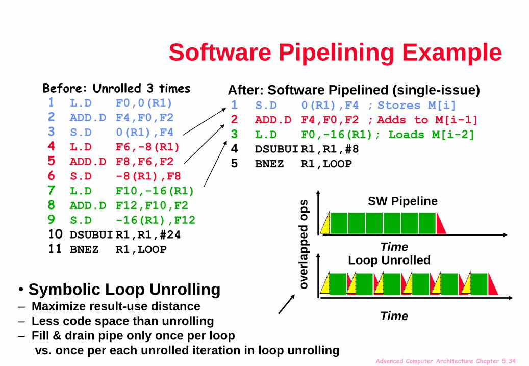
Software Pipelining Example
Before: Unrolled 3 times1 L.D F0,0(R1)
2 ADD.D F4,F0,F2
3 S.D 0(R1),F4
4 L.D F6,-8(R1)
5 ADD.D F8,F6,F2
6 S.D -8(R1),F8
7 L.D F10,-16(R1)
8 ADD.D F12,F10,F2
9 S.D -16(R1),F12
10 DSUBUIR1,R1,#24
11 BNEZ R1,LOOP
After: Software Pipelined (single-issue)1 S.D 0(R1),F4 ; Stores M[i]
2 ADD.D F4,F0,F2 ; Adds to M[i-1]
3 L.D F0,-16(R1); Loads M[i-2]
4 DSUBUIR1,R1,#8
5 BNEZ R1,LOOP
• Symbolic Loop Unrolling– Maximize result-use distance
– Less code space than unrolling
– Fill & drain pipe only once per loop
vs. once per each unrolled iteration in loop unrolling
SW Pipeline
Loop Unrolled
overl
ap
ped
op
sTime
Time

Advanced Computer Architecture Chapter 5.35
Software Pipelining withLoop Unrolling in VLIW
Memory Memory FP FP Int. op/ Clock
reference 1 reference 2 operation 1 op. 2 branch
L.D F0,-48(R1) ST 0(R1),F4 ADD.D F4,F0,F2 1
L.D F6,-56(R1) ST -8(R1),F8 ADD.D F8,F6,F2 DSUBUI R1,R1,#242
L.D F10,-40(R1) ST 8(R1),F12 ADD.D F12,F10,F2 BNEZ R1,LOOP 3
Software pipelined across 9 iterations of original loopIn each iteration of above loop, we:
Store to m,m-8,m-16 (iterations I-3,I-2,I-1)
Compute for m-24,m-32,m-40 (iterations I,I+1,I+2)
Load from m-48,m-56,m-64 (iterations I+3,I+4,I+5)
9 results in 9 cycles, or 1 clock per iteration
Average: 3.67 instrs per clock, 91.75% efficiency
Note: Need fewer registers for software pipelining(only using 7 registers here, was using 15)

Advanced Computer Architecture Chapter 5.36
Trace SchedulingParallelism across IF branches vs. LOOP branches?
Two steps:Trace Selection
Find likely sequence of basic blocks (trace) of (statically predicted or profile predicted) long sequence of straight-line code
Trace Compaction
Squeeze trace into few VLIW instructions
Need bookkeeping code in case prediction is wrong
This is a form of compiler-generated speculationCompiler must generate “fixup” code to handle cases in which trace is not the taken branch
Needs extra registers: undoes bad guess by discarding
Subtle compiler bugs mean wrong answer vs. poorer performance; no hardware interlocks
Some scope for support from instruction set to help with fixup/rollback
Eg Transmeta’s shadow registers, store gate

Advanced Computer Architecture Chapter 5.37
Speculation: HW (Tomasulo) vs. SW (VLIW)HW advantages:
HW better at memory disambiguation since actual addresses are known at runtime
HW better at branch prediction since lower overhead
HW maintains precise exception model
HW does not execute bookkeeping instructions
Same software works across multiple implementations
Smaller code size (not as many nops filling blank instructions)
SW advantages:Window of instructions that is examined for parallelism is unlimited
Reduced transistor count, and power consumption (?)
More elaborate types of speculation can be easier?
Speculation can be based on large-scale program behavior, not just local information

Advanced Computer Architecture Chapter 5.39
Problems with “First Generation” VLIWIncrease in code size
generating enough operations in a straight-line code fragment requires ambitiously unrolling loops
whenever VLIW instructions are not full, unused functional units translate to wasted bits in instruction encoding
Operated in lock-step; no hazard detection HW
a stall in any functional unit pipeline caused entire processor to stall, since all functional units must be kept synchronized
Compiler might know functional unit latencies, but caches harder to predict
Binary code compatibilityPure VLIW => different numbers of functional units and unit latencies require different versions of the code
Advanced Computer Architecture Chapter 5.40
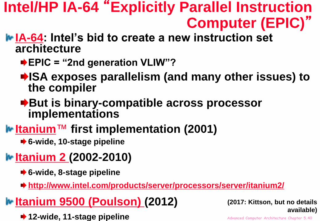
Intel/HP IA-64 “Explicitly Parallel Instruction Computer (EPIC)”
IA-64: Intel’s bid to create a new instruction set architecture
EPIC = “2nd generation VLIW”?
ISA exposes parallelism (and many other issues) to the compiler
But is binary-compatible across processor implementations
Itanium™ first implementation (2001)6-wide, 10-stage pipeline
Itanium 2 (2002-2010)
6-wide, 8-stage pipeline
http://www.intel.com/products/server/processors/server/itanium2/
Itanium 9500 (Poulson) (2012)
12-wide, 11-stage pipeline
(2017: Kittson, but no details
available)

Advanced Computer Architecture Chapter 5.41
Instruction bundling in IA-64
IA-64 instructions are encoded in bundles, which are 128 bits wide.
Each bundle consists of a 5-bit template field and 3 instructions, each 41 bits in length
One purpose of the template field is to mark where instructions in the bundle are dependent or independent, and whether they can be issued in parallel with the next bundle
Eg for Poulson, groups of up to 4 bundles can be issued in parallel
Smaller code size than old VLIW, larger than x86/RISC
htt
p://
www.r
ealw
orldte
ch.c
om/p
age
.cfm
?Art
icleID=RW
T012500000000&p=
4
Instruction group: a sequence of consecutive instructions with no register data dependences
All instructions in a group could be executed in parallel, if sufficient hardware resources exist and if any dependences through memory are preserved
Instruction group can be arbitrarily long, but compiler must explicitly indicate boundary between one instruction group and another by placing a stop between 2 instructions that belong to different groups
Advanced Computer Architecture Chapter 5.42
Instruction bundling in IA-64
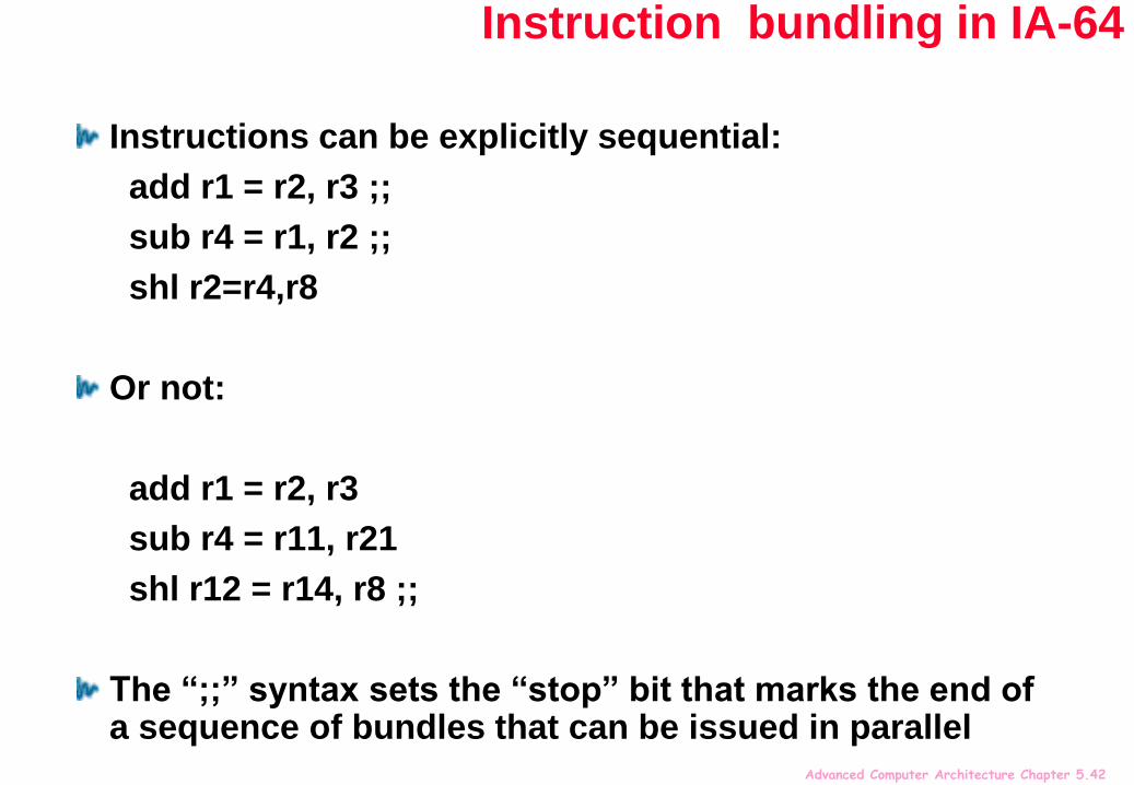
Instructions can be explicitly sequential:
add r1 = r2, r3 ;;
sub r4 = r1, r2 ;;
shl r2=r4,r8
Or not:
add r1 = r2, r3
sub r4 = r11, r21
shl r12 = r14, r8 ;;
The “;;” syntax sets the “stop” bit that marks the end of a sequence of bundles that can be issued in parallel
Advanced Computer Architecture Chapter 5.43
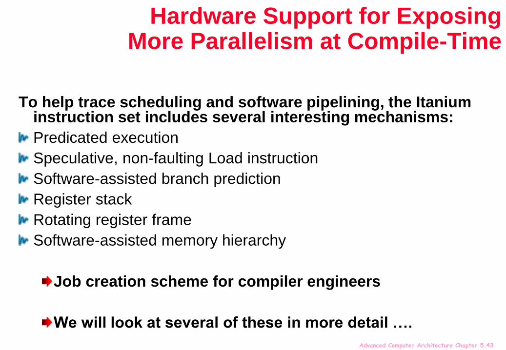
Hardware Support for Exposing More Parallelism at Compile-Time
To help trace scheduling and software pipelining, the Itanium instruction set includes several interesting mechanisms:
Predicated execution
Speculative, non-faulting Load instruction
Software-assisted branch prediction
Register stack
Rotating register frame
Software-assisted memory hierarchy
Job creation scheme for compiler engineers
We will look at several of these in more detail ….

Advanced Computer Architecture Chapter 5.44
IA-64 register stackGeneral-purpose registers are configured to help accelerate procedure calls using a register stack
mechanism similar to that developed in the Berkeley RISC-I processor and used in the SPARC architecture.
Registers 0-31 are always accessible and addressed as 0-31
Registers 32-128 are used as a register stack and each procedure is allocated a set of registers (from 0 to 96)
The new register stack frame is created for a called procedure by renaming the registers in hardware;
a special register called the current frame pointer (CFM) points to the set of registers to be used by a given procedure
main callsf(a,b,c)
f callsg(d,e,f)
g()
abc
def
def
abc

Advanced Computer Architecture Chapter 5.46
Predication…
64 1-bit predicate registers
(p1) add r1 = r2, r3
(p2) sub r1 = r2, r3 ;;
shl r12 = r1, r8
Predication means
Compiler can move instructions across conditional branches
To pack parallel issue groups
May also eliminate some conditional branches completely
Avoiding branch prediction and misprediction
There are also 8 64-bit Branch registers used to hold branch destination addresses for indirect branches – see later
Advanced Computer Architecture Chapter 5.49
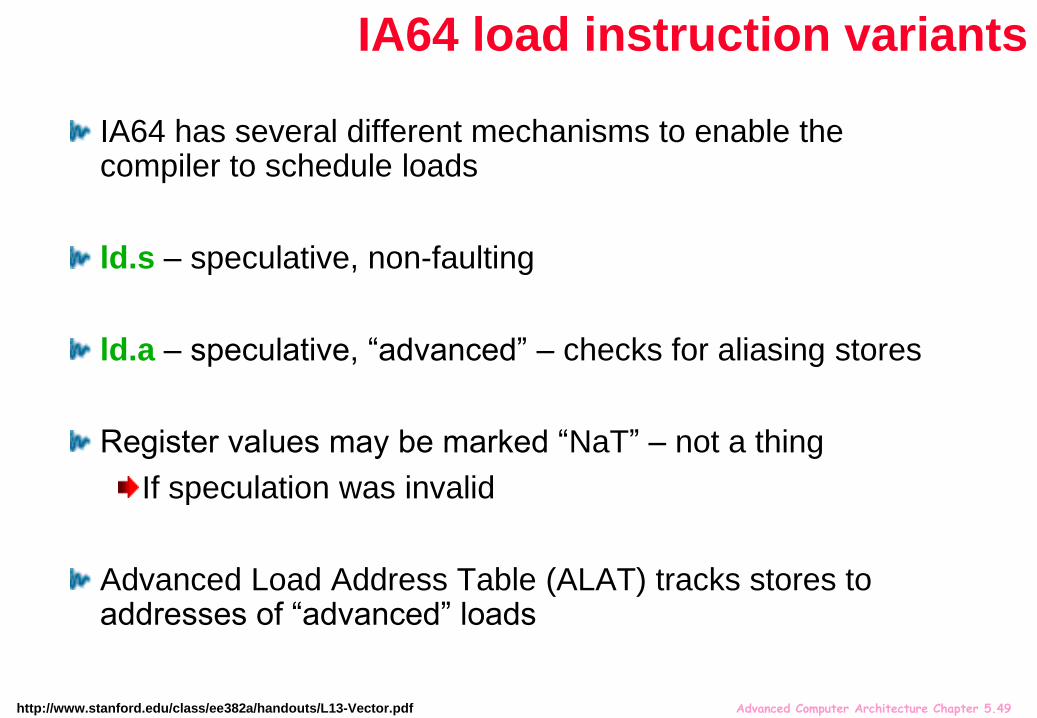
IA64 has several different mechanisms to enable the compiler to schedule loads
ld.s – speculative, non-faulting
ld.a – speculative, “advanced” – checks for aliasing stores
Register values may be marked “NaT” – not a thing
If speculation was invalid
Advanced Load Address Table (ALAT) tracks stores to addresses of “advanced” loads
http://www.stanford.edu/class/ee382a/handouts/L13-Vector.pdf
IA64 load instruction variants
Advanced Computer Architecture Chapter 5.50
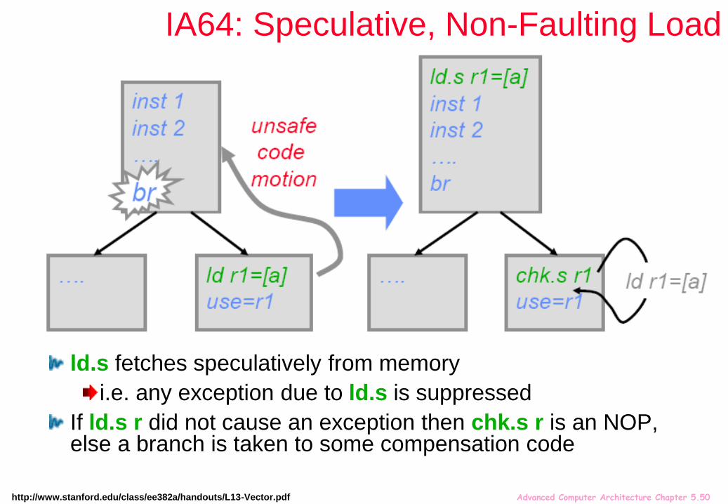
IA64: Speculative, Non-Faulting Load
ld.s fetches speculatively from memory
i.e. any exception due to ld.s is suppressed
If ld.s r did not cause an exception then chk.s r is an NOP, else a branch is taken to some compensation code
http://www.stanford.edu/class/ee382a/handouts/L13-Vector.pdf

Advanced Computer Architecture Chapter 5.51
IA64: Speculative, Non-Faulting Load
Speculatively-loaded data can be consumed prior to check
“speculation” status is propagated with speculated data
Any instruction that uses a speculative result also becomes speculative(i.e. suppressed exceptions)
chk.s checks the entire dataflow sequence for exceptions
http://www.stanford.edu/class/ee382a/handouts/L13-Vector.pdf

Advanced Computer Architecture Chapter 5.52
IA64: Speculative “Advanced” Load
ld.a starts the monitoring of any store to the same address as the advanced load
If no aliasing has occurred since ld.a, ld.c is a NOP
If aliasing has occurred, ld.c re-loads from memory

Advanced Computer Architecture Chapter 5.53
IA64: Branch prediction
Static branch hints can be encoded with every branchtaken vs. not-taken
whether to allocate (or deallocate) an entry in the dynamic BP hardware
(Itanium-1 used a 512-entry 2-level BHT and 64-entry BTB)
TAR (Target Address Register)a small, fully-associative BTAC-like structure
contents are controlled entirely by a “prepare-to-branch” (aka an “importance” hint bit)
a hit in TAR overrides all other predictions
RSB (Return Address Stack)Procedure return addr is pushed (or popped) when a procedure is called (or when it returns)
Predicts nPC when executing register-indirect branches
(see Intel® Itanium® Architecture Developer's Manual, Vol. 3,
http://www.intel.com/content/www/us/en/processors/itanium/itanium-architecture-vol-3-manual.html)
Advanced Computer Architecture Chapter 5.54
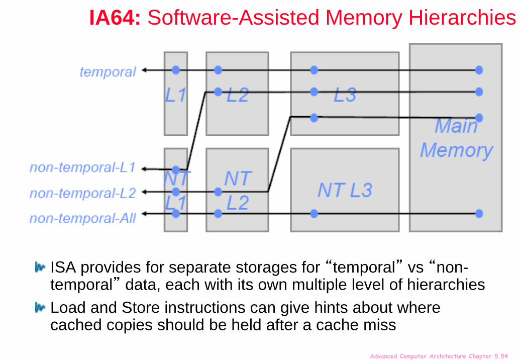
IA64: Software-Assisted Memory Hierarchies
ISA provides for separate storages for “temporal” vs “non-temporal” data, each with its own multiple level of hierarchies
Load and Store instructions can give hints about where cached copies should be held after a cache miss

Advanced Computer Architecture Chapter 5.55
IA-64 Registers
Both the integer and floating point registers support register rotation for registers 32-128.
Register rotation is designed to ease the task of register allocation in software pipelined loops
When combined with predication, possible to avoid the need for unrolling and for separate prologue and epilogue code for a software pipelined loop
makes the SW-pipelining usable for loops with smaller numbers of iterations, where the overheads would traditionally negate many of the advantages

Advanced Computer Architecture Chapter 5.56
How Register Rotation Helps Software Pipelining
The concept of a software pipelining branch:
L1: ld4 r35 = [r4], 4 // post-increment by 4
st4 [r5] = r37, 4 // post-increment by 4
br.ctop L1 ;;
The br.ctop instruction in the example rotates
the general registers (actually br.ctop does more as we shall see)
Therefore the value stored into r35 is read in r37 two
iterations (and two rotations) later.
The register rotation eliminated a dependence between
the load and the store instructions, and allowed the loop to
execute in one cycle.
htt
p:/
/ww
w.c
s.u
alb
ert
a.c
a/~
am
ara
l/co
urs
es/6
80
/web
slid
es/T
F-H
WS
up
So
ftP
ipelin
e/s
ld023.h
tm
Register rotation is useful for procedure calls
It’s also useful for software-pipelined loops
The logical-to-physical register mapping is shifted by 1 each time the branch (“br.ctop”) is executed
One issue packet

Advanced Computer Architecture Chapter 5.57
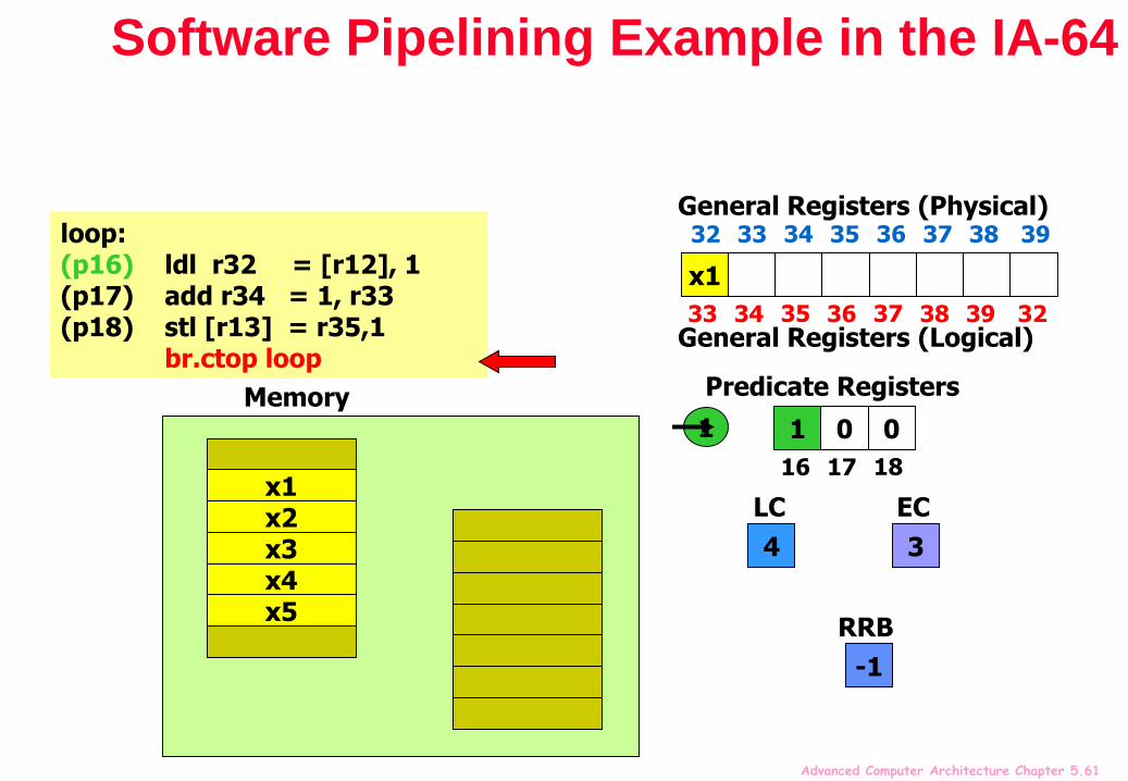
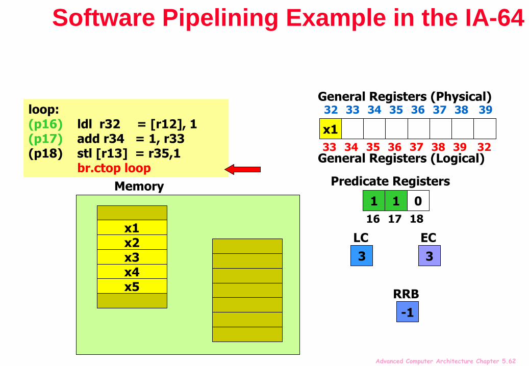
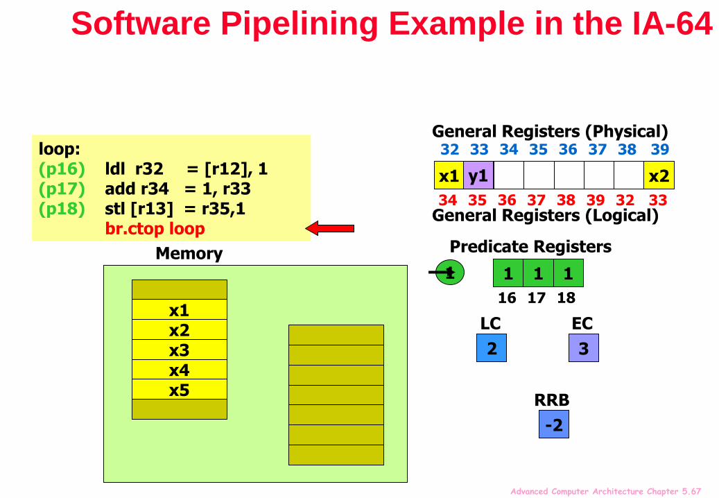
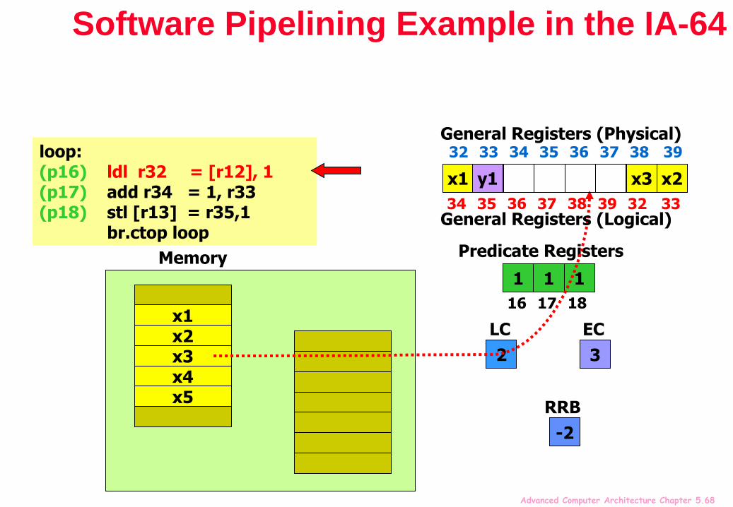
Software Pipelining Example in the IA-64
mov pr.rot = 0 // Clear all rotating predicate registerscmp.eq p16,p0 = r0,r0 // Set p16=1mov ar.lc = 4 // Set loop counter to n-1mov ar.ec = 3 // Set epilog counter to 3
…loop:(p16) ldl r32 = [r12], 1 // Stage 1: load x(p17) add r34 = 1, r33 // Stage 2: y=x+1(p18) stl [r13] = r35,1 // Stage 3: store y
br.ctop loop // Branch back
“Stage” predicate mechanism allows successive stages of the software pipeline to be filled on start-up and drained when the loop terminates
The software pipeline branch “br.ctop” rotates the predicate registers, and injects a 1 into p16
Thus enabling one stage at a time, for execution of prologue
When loop trip count is reached, “br.ctop” injects 0 into p16, disabling one stage at a time, then finally falls-through
htt
p://
www.c
s.ua
lbert
a.c
a/~
amara
l/co
urse
s/680/w
ebslid
es/
TF-HW
Sup
Sof
tPipeline
/sld027.h
tm
One issue packet

Advanced Computer Architecture Chapter 5.58
Software Pipelining Example in the IA-64
loop:(p16) ldl r32 = [r12], 1(p17) add r34 = 1, r33(p18) stl [r13] = r35,1
br.ctop loop
x1
32 33 34 35 36 37 38
General Registers (Physical)
0 01
16 17 18
Predicate Registers
4
LC
3
EC
x4x5
x1x2x3
Memory
39
32 33 34 35 36 37 38 39
General Registers (Logical)
0
RRBhtt
p://
www.c
s.ua
lbert
a.c
a/~
amara
l/co
urse
s/680/w
ebslid
es/
TF-HW
Sup
Sof
tPipeline
/

Advanced Computer Architecture Chapter 5.59
Software Pipelining Example in the IA-64
loop:(p16) ldl r32 = [r12], 1(p17) add r34 = 1, r33(p18) stl [r13] = r35,1
br.ctop loop
0 01
16 17 18
Predicate Registers
4
LC
3
EC
x4x5
x1x2x3
Memory
x1
32 33 34 35 36 37 38
General Registers (Physical)
39
32 33 34 35 36 37 38 39
General Registers (Logical)
0
RRBhtt
p://
www.c
s.ua
lbert
a.c
a/~
amara
l/co
urse
s/680/w
ebslid
es/
TF-HW
Sup
Sof
tPipeline
/

Advanced Computer Architecture Chapter 5.60
Software Pipelining Example in the IA-64
loop:(p16) ldl r32 = [r12], 1(p17) add r34 = 1, r33(p18) stl [r13] = r35,1
br.ctop loop
0 01
16 17 18
Predicate Registers
4
LC
3
EC
x4x5
x1x2x3
Memory
x1
32 33 34 35 36 37 38
General Registers (Physical)
39
32 33 34 35 36 37 38 39
General Registers (Logical)
0
RRBhtt
p://
www.c
s.ua
lbert
a.c
a/~
amara
l/co
urse
s/680/w
ebslid
es/
TF-HW
Sup
Sof
tPipeline
/
Advanced Computer Architecture Chapter 5.61
Software Pipelining Example in the IA-64
loop:(p16) ldl r32 = [r12], 1(p17) add r34 = 1, r33(p18) stl [r13] = r35,1
br.ctop loop
0 01
16 17 18
Predicate Registers
4
LC
3
EC
1
x4x5
x1x2x3
Memory
x1
33 34 35 36 37 38 39
General Registers (Physical)
32
32 33 34 35 36 37 38 39
General Registers (Logical)
-1
RRB
Advanced Computer Architecture Chapter 5.62
Software Pipelining Example in the IA-64
loop:(p16) ldl r32 = [r12], 1(p17) add r34 = 1, r33(p18) stl [r13] = r35,1
br.ctop loop
1 01
16 17 18
Predicate Registers
3
LC
3
EC
x4x5
x1x2x3
Memory
x1
33 34 35 36 37 38 39
General Registers (Physical)
32
32 33 34 35 36 37 38 39
General Registers (Logical)
-1
RRB

Advanced Computer Architecture Chapter 5.63
Software Pipelining Example in the IA-64
loop:(p16) ldl r32 = [r12], 1(p17) add r34 = 1, r33(p18) stl [r13] = r35,1
br.ctop loop
1 01
16 17 18
Predicate Registers
3
LC
3
EC
x4x5
x1x2x3
Memory
x1
33 34 35 36 37 38 39
General Registers (Physical)
32
32 33 34 35 36 37 38 39
General Registers (Logical)
x2
-1
RRB

Advanced Computer Architecture Chapter 5.64
Software Pipelining Example in the IA-64
loop:(p16) ldl r32 = [r12], 1(p17) add r34 = 1, r33(p18) stl [r13] = r35,1
br.ctop loop
1 01
16 17 18
Predicate Registers
3
LC
3
EC
x4x5
x1x2x3
Memory
x1
33 34 35 36 37 38 39
General Registers (Physical)
32
32 33 34 35 36 37 38 39
General Registers (Logical)
x2y1
-1
RRB

Advanced Computer Architecture Chapter 5.65
Software Pipelining Example in the IA-64
loop:(p16) ldl r32 = [r12], 1(p17) add r34 = 1, r33(p18) stl [r13] = r35,1
br.ctop loop
1 01
16 17 18
Predicate Registers
3
LC
3
EC
x4x5
x1x2x3
Memory
x1
33 34 35 36 37 38 39
General Registers (Physical)
32
32 33 34 35 36 37 38 39
General Registers (Logical)
x2y1
-1
RRB

Advanced Computer Architecture Chapter 5.66
Software Pipelining Example in the IA-64
loop:(p16) ldl r32 = [r12], 1(p17) add r34 = 1, r33(p18) stl [r13] = r35,1
br.ctop loop
1 01
16 17 18
Predicate Registers
3
LC
3
EC
x4x5
x1x2x3
Memory
x1
33 34 35 36 37 38 39
General Registers (Physical)
32
32 33 34 35 36 37 38 39
General Registers (Logical)
x2y1
-1
RRB
Advanced Computer Architecture Chapter 5.67
Software Pipelining Example in the IA-64
loop:(p16) ldl r32 = [r12], 1(p17) add r34 = 1, r33(p18) stl [r13] = r35,1
br.ctop loop
1 11
16 17 18
Predicate Registers
2
LC
3
EC
1
x4x5
x1x2x3
Memory
x1
34 35 36 37 38 39 32
General Registers (Physical)
33
32 33 34 35 36 37 38 39
General Registers (Logical)
x2y1
-2
RRB
Advanced Computer Architecture Chapter 5.68
Software Pipelining Example in the IA-64
loop:(p16) ldl r32 = [r12], 1(p17) add r34 = 1, r33(p18) stl [r13] = r35,1
br.ctop loop
1 11
16 17 18
Predicate Registers
2
LC
3
EC
x4x5
x1x2x3
Memory
x1
34 35 36 37 38 39 32
General Registers (Physical)
33
32 33 34 35 36 37 38 39
General Registers (Logical)
x2y1 x3
-2
RRB

Advanced Computer Architecture Chapter 5.69
Software Pipelining Example in the IA-64
loop:(p16) ldl r32 = [r12], 1(p17) add r34 = 1, r33(p18) stl [r13] = r35,1
br.ctop loop
y2
1 11
16 17 18
Predicate Registers
2
LC
3
EC
x4x5
x1x2x3
Memory
34 35 36 37 38 39 32
General Registers (Physical)
33
32 33 34 35 36 37 38 39
General Registers (Logical)
x2y1 x3
-2
RRB

Advanced Computer Architecture Chapter 5.70
Software Pipelining Example in the IA-64
loop:(p16) ldl r32 = [r12], 1(p17) add r34 = 1, r33(p18) stl [r13] = r35,1
br.ctop loop
1 11
16 17 18
Predicate Registers
2
LC
3
EC
x4x5
x1x2x3 y1
Memory
y2
34 35 36 37 38 39 32
General Registers (Physical)
33
32 33 34 35 36 37 38 39
General Registers (Logical)
x2y1 x3
-2
RRB

Advanced Computer Architecture Chapter 5.71
Software Pipelining Example in the IA-64
loop:(p16) ldl r32 = [r12], 1(p17) add r34 = 1, r33(p18) stl [r13] = r35,1
br.ctop loop
1 11
16 17 18
Predicate Registers
2
LC
3
EC
x4x5
x1x2x3 y1
Memory
y2
34 35 36 37 38 39 32
General Registers (Physical)
33
32 33 34 35 36 37 38 39
General Registers (Logical)
x2y1 x3
-2
RRB
Advanced Computer Architecture Chapter 5.81
Hidden slides…
Some hidden slides are not in handout
We continue with start of pipeline drain phase

Advanced Computer Architecture Chapter 5.82
Software Pipelining Example in the IA-64
1 11
16 17 18
Predicate Registers
0
LC
3
EC
loop:(p16) ldl r32 = [r12], 1(p17) add r34 = 1, r33(p18) stl [r13] = r35,1
br.ctop loop
x4x5
x1x2x3 y1
y2y3
Memory
y2 x5 x436 37 38 39 32 33 34
General Registers (Physical)
35
32 33 34 35 36 37 38 39
General Registers (Logical)
y3y1 y4
-4
RRB

Advanced Computer Architecture Chapter 5.83
Software Pipelining Example in the IA-64
1 10
16 17 18
Predicate Registers
0
LC
2
EC
loop:(p16) ldl r32 = [r12], 1(p17) add r34 = 1, r33(p18) stl [r13] = r35,1
br.ctop loop
0
x4x5
x1x2x3 y1
y2y3
Memory
y2 x5 x437 38 39 32 33 34 35
General Registers (Physical)
36
32 33 34 35 36 37 38 39
General Registers (Logical)
y3y1 y4
-5
RRB

Advanced Computer Architecture Chapter 5.89
Software Pipelining Example in the IA-64
0 10
16 17 18
Predicate Registers
0
LC
1
EC
loop:(p16) ldl r32 = [r12], 1(p17) add r34 = 1, r33(p18) stl [r13] = r35,1
br.ctop loop
0
x4x5
x1x2x3
y4
y1y2y3
Memory
y2 x5 y536 37 38 39 32 33 34
General Registers (Physical)
35
32 33 34 35 36 37 38 39
General Registers (Logical)
y3y1 y4
-6
RRB

Advanced Computer Architecture Chapter 5.95
Software Pipelining Example in the IA-64
0 00
16 17 18
Predicate Registers
0
LC
0
EC
loop:(p16) ldl r32 = [r12], 1(p17) add r34 = 1, r33(p18) stl [r13] = r35,1
br.ctop loop
0
x4x5
x1x2x3
y4y5
y1y2y3
Memory
y2 x5 y537 38 39 32 33 34 35
General Registers (Physical)
36
32 33 34 35 36 37 38 39
General Registers (Logical)
y3y1 y4
-7
RRB

Advanced Computer Architecture Chapter 5.96
FPUIA-32
Control
Instr.
Fetch &
DecodeCache
Cache
TLB
Integer Units
IA-64 Control
Bus
Core Processor Die 4 x 1MB L3 cache
Itanium™ Processor Silicon(Copyright: Intel at Hotchips ’00)
Caches
32KB L1 (2 cycle)
96KB L2 (7 cycle)
2 or 4 MB L3 (off chip)
133 MHz 64-bit bus
SpecFP: 711
SpecInt: 404
36-bit addresses (64GB)

Advanced Computer Architecture Chapter 5.98
Branch Hints
Memory Hints
Instruction
Cache
& Branch
Predictors
Fetch Memory
Subsystem
Three
levels of
cache:L1, L2, L3
Register Stack & Rotation
Explicit Parallelism
128 GR &
128 FR,
Register
Remap
&
Stack
Engine
Register
Handling
Fast, S
imp
le 6
-Issu
e
Issue Control
Micro-architecture Features in hardware:
Itanium™ EPIC Design Maximizes SW-HW Synergy(Copyright: Intel at Hotchips ’00)
Architecture Features programmed by compiler:
PredicationData & Control
Speculation
Byp
as
se
s &
De
pe
nd
en
cie
s
Parallel Resources
4 Integer +
4 MMX Units
2 FMACs
(4 for SSE)
2 L.D/ST units
32 entry ALAT
Speculation Deferral Management

Advanced Computer Architecture Chapter 5.99
10 Stage In-Order Core Pipeline(Copyright: Intel at Hotchips ’00)
Front End•Pre-fetch/Fetch of up to 6
instructions/cycle
•Hierarchy of branch
predictors
•Decoupling buffer
Instruction Delivery•Dispersal of up to 6
instructions on 9 ports
•Reg. remapping
•Reg. stack engine
Operand Delivery• Reg read + Bypasses
• Register scoreboard
• Predicated
dependencies
Execution• 4 single cycle ALUs, 2 ld/str
• Advanced load control
• Predicate delivery & branch
• Nat/Exception//Retirement
IPG FET ROT EXP REN REG EXE DET WRBWL.D
REGISTER READ
WORD-LINE
DECODERENAMEEXPAND
INST POINTER
GENERATION
FETCH ROTATE EXCEPTION
DETECT
EXECUTE WRITE-BACK

Advanced Computer Architecture Chapter 5.102
Itanium 2
221M transistors
19.5 x 21.6 mmhttp://cpus.hp.com/technical_references/
Caches
32KB L1 (1 cycle)
256KB L2 (5 cycle)
3 MB L3 (on chip)
200 MHz 128-bit Bus
SpecFP: 1356
SpecInt: 810
44-bit addresses (18TB)

Advanced Computer Architecture Chapter 5.103
Comments on Itanium
Remarkably, the Itanium has many of the features more commonly associated with the dynamically-scheduled pipelines
strong emphasis on branch prediction
register renaming,
scoreboarding,
a deep pipeline with many stages before execution (to handle instruction alignment, renaming, etc.),
several stages following execution to handle exception detection
Surprising that an approach whose goal is to rely on compiler technology and simpler HW seems to be at least as complex as dynamically scheduled processors!

Advanced Computer Architecture Chapter 5.104
Comments on Itanium
Compare Itanium II
With IBM Power 4:
IPG FET ROT EXP REN REG EXE DET WRBWL.D
INST POINTER
GENERATION
FETCH ROTATE EXCEPTION
DETECT
EXECUTE WRITE-BACK
http://ixbtlabs.com/articles/ibmpower4/

Advanced Computer Architecture Chapter 5.105
EPIC/IA-64/Itanium principlesStart loads early
advance loads - move above stores when alias analyis is incomplete
speculative loads - move above branches
Predication to eliminate many conditional branches64 predicate registers
almost every instruction is predicated
register rich128 integer registers (64 bits each)
128 floating-point registers
Independence architectureVLIW flavor, but fully interlocked (i.e., no delay slots)
three 41-bit instruction syllables per 128-bit "bundle"
each bundle contains 5 "template bits" which specify independence of following syllables (within bundle and between bundles)
unbundled branch architectureeight branch registers
multiway branches
Rotating register fileslower 48 of the predicate registers rotate
lower 96 of the integer registers rotate
Advanced Computer Architecture Chapter 5.106
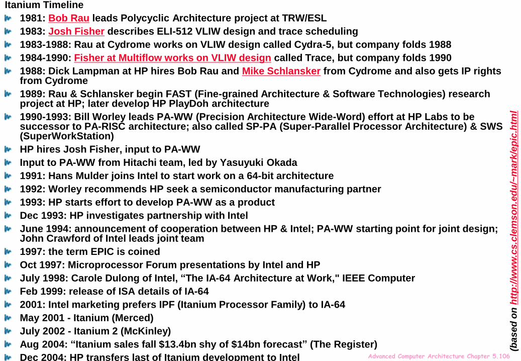
Itanium Timeline
1981: Bob Rau leads Polycyclic Architecture project at TRW/ESL
1983: Josh Fisher describes ELI-512 VLIW design and trace scheduling
1983-1988: Rau at Cydrome works on VLIW design called Cydra-5, but company folds 1988
1984-1990: Fisher at Multiflow works on VLIW design called Trace, but company folds 1990
1988: Dick Lampman at HP hires Bob Rau and Mike Schlansker from Cydrome and also gets IP rights from Cydrome
1989: Rau & Schlansker begin FAST (Fine-grained Architecture & Software Technologies) research project at HP; later develop HP PlayDoh architecture
1990-1993: Bill Worley leads PA-WW (Precision Architecture Wide-Word) effort at HP Labs to be successor to PA-RISC architecture; also called SP-PA (Super-Parallel Processor Architecture) & SWS (SuperWorkStation)
HP hires Josh Fisher, input to PA-WW
Input to PA-WW from Hitachi team, led by Yasuyuki Okada
1991: Hans Mulder joins Intel to start work on a 64-bit architecture
1992: Worley recommends HP seek a semiconductor manufacturing partner
1993: HP starts effort to develop PA-WW as a product
Dec 1993: HP investigates partnership with Intel
June 1994: announcement of cooperation between HP & Intel; PA-WW starting point for joint design; John Crawford of Intel leads joint team
1997: the term EPIC is coined
Oct 1997: Microprocessor Forum presentations by Intel and HP
July 1998: Carole Dulong of Intel, “The IA-64 Architecture at Work," IEEE Computer
Feb 1999: release of ISA details of IA-64
2001: Intel marketing prefers IPF (Itanium Processor Family) to IA-64
May 2001 - Itanium (Merced)
July 2002 - Itanium 2 (McKinley)
Aug 2004: “Itanium sales fall $13.4bn shy of $14bn forecast” (The Register)
Dec 2004: HP transfers last of Itanium development to Intel
(ba
se
d o
n h
ttp
://w
ww
.cs.c
lem
so
n.e
du
/~m
ark
/ep
ic.h
tml

Advanced Computer Architecture Chapter 5.107
Itanium supercomputer
• NASA's 10,240-processor Columbia supercomputer (2004-2013) built from 20 Altix
systems, each powered by 512 Intel Itanium 2 processors. Peak performance 42.7
TeraFlops; 20TB RAM. Single shared address space. Ran Linux. (Image courtesy of
Silicon Graphics, Inc.)• http://www.nas.nasa.gov/hecc/resources/columbia.html
htt
p:/
/ww
w.in
tel.co
m/t
ech
no
log
y/c
om
pu
tin
g/h
w1
00
41
.htm

Advanced Computer Architecture Chapter 5.108
Aces Hardware analysis of SPEC benchmark data http://www.aceshardware.com/SPECmine/top.jsp
http://www.spec.org/cpu2006/results/cpu2006.html
Advanced Computer Architecture Chapter 5.109
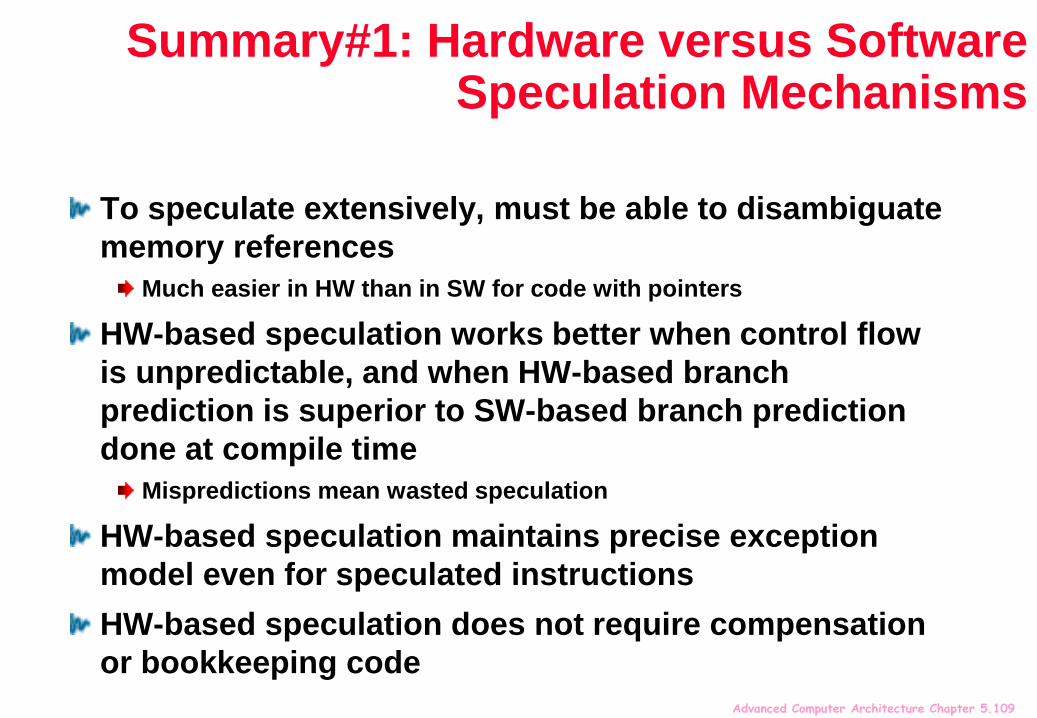
Summary#1: Hardware versus Software Speculation Mechanisms
To speculate extensively, must be able to disambiguate
memory references
Much easier in HW than in SW for code with pointers
HW-based speculation works better when control flow
is unpredictable, and when HW-based branch
prediction is superior to SW-based branch prediction
done at compile time
Mispredictions mean wasted speculation
HW-based speculation maintains precise exception
model even for speculated instructions
HW-based speculation does not require compensation
or bookkeeping code
Advanced Computer Architecture Chapter 5.110
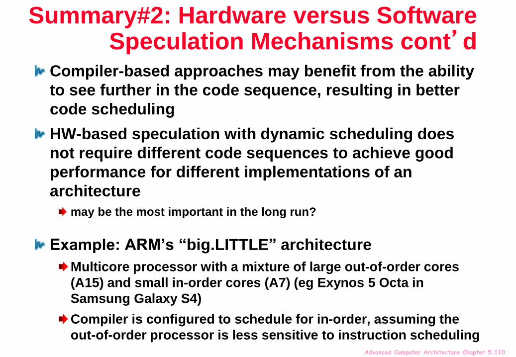
Summary#2: Hardware versus Software Speculation Mechanisms cont’d
Compiler-based approaches may benefit from the ability
to see further in the code sequence, resulting in better
code scheduling
HW-based speculation with dynamic scheduling does
not require different code sequences to achieve good
performance for different implementations of an
architecture
may be the most important in the long run?
Example: ARM’s “big.LITTLE” architecture
Multicore processor with a mixture of large out-of-order cores
(A15) and small in-order cores (A7) (eg Exynos 5 Octa in
Samsung Galaxy S4)
Compiler is configured to schedule for in-order, assuming the
out-of-order processor is less sensitive to instruction scheduling

Advanced Computer Architecture Chapter 5.111
Summary #3: Software Scheduling
Instruction Level Parallelism (ILP) found either by compiler or
hardware.
Loop level parallelism is easiest to see
SW dependencies/compiler sophistication determine if compiler can unroll
loops
Memory dependencies hardest to determine => Memory disambiguation
Very sophisticated transformations available
Trace scheduling to parallelize if statements
Superscalar and VLIW: CPI < 1 (IPC > 1)
Dynamic issue vs. Static issue
More instructions issue at same time => larger hazard penalty
Limitation is often number of instructions that you can successfully fetch and
decode per cycle

Advanced Computer Architecture Chapter 5.112
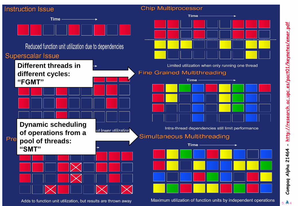
Beyond ILP: Multithreading, Simultaneous Multithreading (SMT)
Cray/Tera MTAhttp://www.cray.com/products/systems/mta/, http://www.utc.edu/~jdumas/cs460/papersfa01/craymta/
(Source: Asanovic http://www.cag.lcs.mit.edu/6.893-f2000/lectures/l06-tera.pdf)

Advanced Computer Architecture Chapter 5.113
Com
paq
Alpha 2
1464 -
htt
p://
rese
arc
h.a
c.up
c.es/
pact
01/k
eyno
tes/
emer.
Advanced Computer Architecture Chapter 5.114
Com
paq
Alpha 2
1464 -
htt
p://
rese
arc
h.a
c.up
c.es/
pact
01/k
eyno
tes/
emer.
Different threads in
different cycles:
“FGMT”
Dynamic scheduling
of operations from a
pool of threads:
“SMT”

Advanced Computer Architecture Chapter 5.115
SMT
Alpha 21464
One CPU with 4 Thread Processing Units (TPUs)
“6% area overhead over single-thread 4-issue CPU”

Advanced Computer Architecture Chapter 5.116
SMT performance
Alpha 21464
Intel Pentium 4 with hyperthreading:
http://www.intel.com/technology/itj/2002/volume06issue01/vol6iss1_hyper_threadi
ng_technology.pdf
Advanced Computer Architecture Chapter 5.117
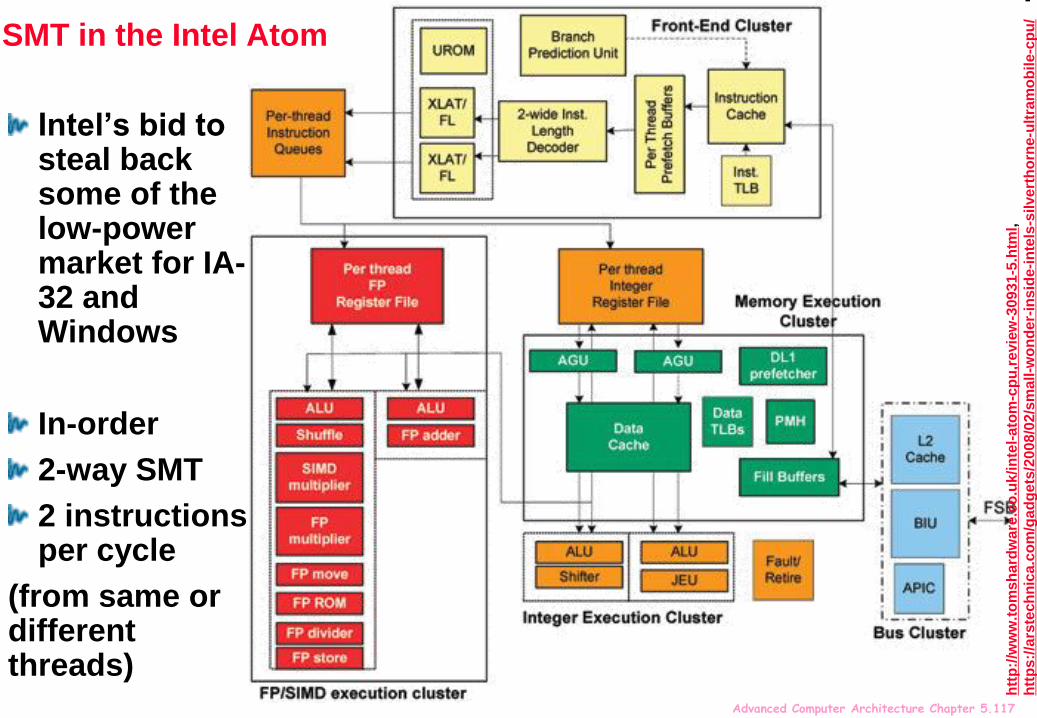
SMT in the Intel Atom
Intel’s bid to steal back some of the low-power market for IA-32 and Windows
In-order
2-way SMT
2 instructions per cycle
(from same or different threads)
htt
p:/
/ww
w.t
om
sh
ard
wa
re.c
o.u
k/in
tel-
ato
m-c
pu
,re
vie
w-3
0931-5
.htm
l,
htt
ps:/
/ars
tech
nic
a.c
om
/gad
gets
/2008/0
2/s
mall-w
on
der-
insid
e-i
nte
ls-s
ilvert
ho
rne-u
ltra
mo
bile
-cp
u/

Advanced Computer Architecture Chapter 5.118
SMT issuesEach thread runs slow?The point of Simultaneous Multithreading is that resources are dynamically assigned, so if only one thread can run it can run faster
SMT threads contend for resourcesPossibly symbiotically?
One thread is memory-intensive, one arithmetic-intensive?
Possibly destructively
thrashing the cache? Other shared resources…. (TLB?)
Which resources should be partitioned per-thread, and which should be shared on-demand?
SMT threads need to be scheduled fairlyCan one thread monopolise the whole CPU?
Denial of service risk
Slow thread that suffers lots of cache misses fills RUU and blocks issue
Advanced Computer Architecture Chapter 5.119
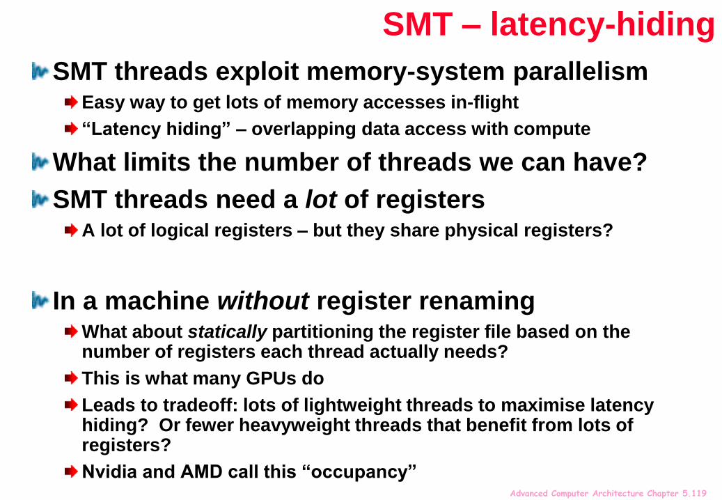
SMT – latency-hiding
SMT threads exploit memory-system parallelismEasy way to get lots of memory accesses in-flight
“Latency hiding” – overlapping data access with compute
What limits the number of threads we can have?
SMT threads need a lot of registersA lot of logical registers – but they share physical registers?
In a machine without register renamingWhat about statically partitioning the register file based on the number of registers each thread actually needs?
This is what many GPUs do
Leads to tradeoff: lots of lightweight threads to maximise latency hiding? Or fewer heavyweight threads that benefit from lots of registers?
Nvidia and AMD call this “occupancy”

Advanced Computer Architecture Chapter 5.120
Mapping threads into the register fileIf each thread needs few registers, we can have lots of them co-existing in the same physical register file
Alternatively, we could have fewer, fatter threads
More threads=higher “occupancy”
Better latency hiding
Tricky tradeoff!

Advanced Computer Architecture Chapter 5.121
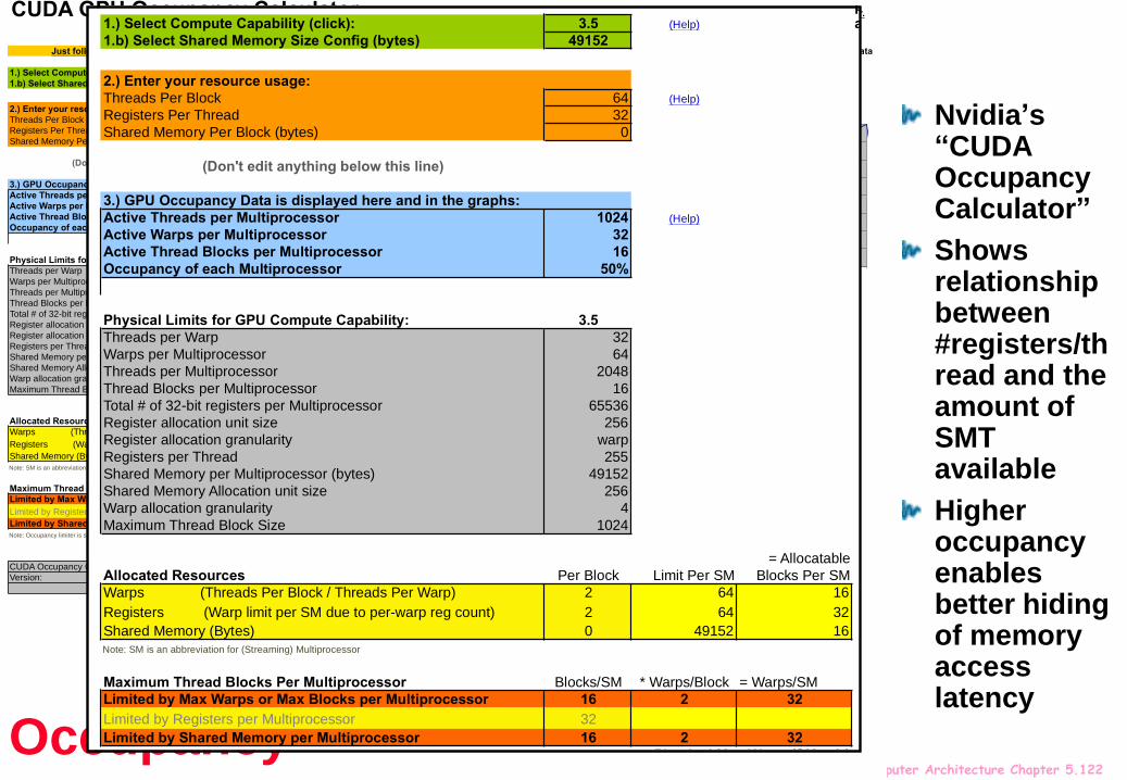
Nvidia’s “CUDA Occupancy Calculator”
Shows relationship between #registers/thread and the amount of SMT available
Higher occupancy enables better hiding of memory access latency
CUDA GPU Occupancy Calculator
1.) Select Compute Capability (click): 3.5 (Help)
1.b) Select Shared Memory Size Config (bytes) 49152
2.) Enter your resource usage:
Threads Per Block 64 (Help)
Registers Per Thread 32
Shared Memory Per Block (bytes) 0
(Don't edit anything below this line)
3.) GPU Occupancy Data is displayed here and in the graphs:
Active Threads per Multiprocessor 1024 (Help)
Active Warps per Multiprocessor 32
Active Thread Blocks per Multiprocessor 16
Occupancy of each Multiprocessor 50%
Physical Limits for GPU Compute Capability: 3.5
Threads per Warp 32
Warps per Multiprocessor 64
Threads per Multiprocessor 2048
Thread Blocks per Multiprocessor 16
Total # of 32-bit registers per Multiprocessor 65536
Register allocation unit size 256
Register allocation granularity warp
Registers per Thread 255
Shared Memory per Multiprocessor (bytes) 49152
Shared Memory Allocation unit size 256
Warp allocation granularity 4
Maximum Thread Block Size 1024
Allocated Resources Per Block Limit Per SM
= Allocatable
Blocks Per SM
Warps (Threads Per Block / Threads Per Warp) 2 64 16
Registers (Warp limit per SM due to per-warp reg count) 2 64 32
Shared Memory (Bytes) 0 49152 16
Note: SM is an abbreviation for (Streaming) Multiprocessor
Maximum Thread Blocks Per Multiprocessor Blocks/SM * Warps/Block = Warps/SM
Limited by Max Warps or Max Blocks per Multiprocessor 16 2 32
Limited by Registers per Multiprocessor 32 2 0
Limited by Shared Memory per Multiprocessor 16 2 32
Note: Occupancy limiter is shown in orange
CUDA Occupancy Calculator
Version: 5.1
Threads Warps/Multiprocessor Registers Warps/Multiprocessor Shared MemoryWarps/Multiprocessor
64 32 32 32 0 32
32 16 1 32 0 32
64 32 2 32 512 32
96 48 3 32 1024 32
128 64 4 32 1536 32
160 60 5 32 2048 32
192 60 6 32 2560 32
224 63 7 32 3072 32
256 64 8 32 3584 26
288 63 9 32 4096 24
320 60 10 32 4608 20
352 55 11 32 5120 18
384 60 12 32 5632 16
416 52 13 32 6144 16
448 56 14 32 6656 14
480 60 15 32 7168 12
512 64 16 32 7680 12
544 51 17 32 8192 12
576 54 18 32 8704 10
608 57 19 32 9216 10
640 60 20 32 9728 10
Click Here for detailed instructions on how to use this occupancy calculator.
For more information on NVIDIA CUDA, visit http://developer.nvidia.com/cuda
Copyright and License
Just follow steps 1, 2, and 3 below! (or click here for help)
Physical Max Warps/SM = 64
Occupancy = 32 / 64 = 50%
Your chosen resource usage is indicated by the red triangle on the graphs. The other data
points represent the range of possible block sizes, register counts, and shared memory
allocation.
My Block Size 64
0
8
16
24
32
40
48
56
64
0 64 128 192 256 320 384 448 512 576 640 704 768 832 896 960 1024
Mu
ltip
roce
sso
r W
arp
Occu
pa
nc
y
(# w
arp
s)
Threads Per Block
Impact of Varying Block Size
My Register Count 32
0
8
16
24
32
40
48
56
64
0
8
16
24
32
40
48
56
64
72
80
88
96
10
4
11
2
12
0
12
8
13
6
14
4
15
2
16
0
16
8
17
6
18
4
19
2
20
0
20
8
21
6
22
4
23
2
24
0
24
8
25
6
Mu
ltip
roce
sso
r W
arp
Occu
pan
cy
(# w
arp
s)
Registers Per Thread
Impact of Varying Register Count Per Thread
My Shared Memory 0
0
8
16
24
32
40
48
56
64
0
20
48
40
96
61
44
81
92
10
240
12
288
14
336
16
384
18
432
20
480
22
528
24
576
26
624
28
672
30
720
32
768
34
816
36
864
38
912
40
960
43
008
45
056
47
104
49
152
Mu
ltip
roces
so
r W
arp
Occu
pa
nc
y
(#w
arp
s)
Shared Memory Per Block
Impact of Varying Shared Memory Usage Per Block
Occupancy
Advanced Computer Architecture Chapter 5.122
Nvidia’s “CUDA Occupancy Calculator”
Shows relationship between #registers/thread and the amount of SMT available
Higher occupancy enables better hiding of memory access latency
CUDA GPU Occupancy Calculator
1.) Select Compute Capability (click): 3.5 (Help)
1.b) Select Shared Memory Size Config (bytes) 49152
2.) Enter your resource usage:
Threads Per Block 64 (Help)
Registers Per Thread 32
Shared Memory Per Block (bytes) 0
(Don't edit anything below this line)
3.) GPU Occupancy Data is displayed here and in the graphs:
Active Threads per Multiprocessor 1024 (Help)
Active Warps per Multiprocessor 32
Active Thread Blocks per Multiprocessor 16
Occupancy of each Multiprocessor 50%
Physical Limits for GPU Compute Capability: 3.5
Threads per Warp 32
Warps per Multiprocessor 64
Threads per Multiprocessor 2048
Thread Blocks per Multiprocessor 16
Total # of 32-bit registers per Multiprocessor 65536
Register allocation unit size 256
Register allocation granularity warp
Registers per Thread 255
Shared Memory per Multiprocessor (bytes) 49152
Shared Memory Allocation unit size 256
Warp allocation granularity 4
Maximum Thread Block Size 1024
Allocated Resources Per Block Limit Per SM
= Allocatable
Blocks Per SM
Warps (Threads Per Block / Threads Per Warp) 2 64 16
Registers (Warp limit per SM due to per-warp reg count) 2 64 32
Shared Memory (Bytes) 0 49152 16
Note: SM is an abbreviation for (Streaming) Multiprocessor
Maximum Thread Blocks Per Multiprocessor Blocks/SM * Warps/Block = Warps/SM
Limited by Max Warps or Max Blocks per Multiprocessor 16 2 32
Limited by Registers per Multiprocessor 32 2 0
Limited by Shared Memory per Multiprocessor 16 2 32
Note: Occupancy limiter is shown in orange
CUDA Occupancy Calculator
Version: 5.1
Threads Warps/Multiprocessor Registers Warps/Multiprocessor Shared MemoryWarps/Multiprocessor
64 32 32 32 0 32
32 16 1 32 0 32
64 32 2 32 512 32
96 48 3 32 1024 32
128 64 4 32 1536 32
160 60 5 32 2048 32
192 60 6 32 2560 32
224 63 7 32 3072 32
256 64 8 32 3584 26
288 63 9 32 4096 24
320 60 10 32 4608 20
352 55 11 32 5120 18
384 60 12 32 5632 16
416 52 13 32 6144 16
448 56 14 32 6656 14
480 60 15 32 7168 12
512 64 16 32 7680 12
544 51 17 32 8192 12
576 54 18 32 8704 10
608 57 19 32 9216 10
640 60 20 32 9728 10
Click Here for detailed instructions on how to use this occupancy calculator.
For more information on NVIDIA CUDA, visit http://developer.nvidia.com/cuda
Copyright and License
Just follow steps 1, 2, and 3 below! (or click here for help)
Physical Max Warps/SM = 64
Occupancy = 32 / 64 = 50%
Your chosen resource usage is indicated by the red triangle on the graphs. The other data
points represent the range of possible block sizes, register counts, and shared memory
allocation.
My Block Size 64
0
8
16
24
32
40
48
56
64
0 64 128 192 256 320 384 448 512 576 640 704 768 832 896 960 1024
Mu
ltip
roce
sso
r W
arp
Occu
pa
nc
y
(# w
arp
s)
Threads Per Block
Impact of Varying Block Size
My Register Count 32
0
8
16
24
32
40
48
56
64
0
8
16
24
32
40
48
56
64
72
80
88
96
10
4
11
2
12
0
12
8
13
6
14
4
15
2
16
0
16
8
17
6
18
4
19
2
20
0
20
8
21
6
22
4
23
2
24
0
24
8
25
6
Mu
ltip
roce
sso
r W
arp
Occu
pan
cy
(# w
arp
s)
Registers Per Thread
Impact of Varying Register Count Per Thread
My Shared Memory 0
0
8
16
24
32
40
48
56
64
0
20
48
40
96
61
44
81
92
10
240
12
288
14
336
16
384
18
432
20
480
22
528
24
576
26
624
28
672
30
720
32
768
34
816
36
864
38
912
40
960
43
008
45
056
47
104
49
152
Mu
ltip
roces
so
r W
arp
Occu
pa
nc
y
(#w
arp
s)
Shared Memory Per Block
Impact of Varying Shared Memory Usage Per Block
Occupancy
CUDA GPU Occupancy Calculator
1.) Select Compute Capability (click): 3.5 (Help)
1.b) Select Shared Memory Size Config (bytes) 49152
2.) Enter your resource usage:
Threads Per Block 64 (Help)
Registers Per Thread 32
Shared Memory Per Block (bytes) 0
(Don't edit anything below this line)
3.) GPU Occupancy Data is displayed here and in the graphs:
Active Threads per Multiprocessor 1024 (Help)
Active Warps per Multiprocessor 32
Active Thread Blocks per Multiprocessor 16
Occupancy of each Multiprocessor 50%
Physical Limits for GPU Compute Capability: 3.5
Threads per Warp 32
Warps per Multiprocessor 64
Threads per Multiprocessor 2048
Thread Blocks per Multiprocessor 16
Total # of 32-bit registers per Multiprocessor 65536
Register allocation unit size 256
Register allocation granularity warp
Registers per Thread 255
Shared Memory per Multiprocessor (bytes) 49152
Shared Memory Allocation unit size 256
Warp allocation granularity 4
Maximum Thread Block Size 1024
Allocated Resources Per Block Limit Per SM
= Allocatable
Blocks Per SM
Warps (Threads Per Block / Threads Per Warp) 2 64 16
Registers (Warp limit per SM due to per-warp reg count) 2 64 32
Shared Memory (Bytes) 0 49152 16
Note: SM is an abbreviation for (Streaming) Multiprocessor
Maximum Thread Blocks Per Multiprocessor Blocks/SM * Warps/Block = Warps/SM
Limited by Max Warps or Max Blocks per Multiprocessor 16 2 32
Limited by Registers per Multiprocessor 32 2 0
Limited by Shared Memory per Multiprocessor 16 2 32
Note: Occupancy limiter is shown in orange
CUDA Occupancy Calculator
Version: 5.1
Threads Warps/Multiprocessor Registers Warps/Multiprocessor Shared MemoryWarps/Multiprocessor
64 32 32 32 0 32
32 16 1 32 0 32
64 32 2 32 512 32
96 48 3 32 1024 32
128 64 4 32 1536 32
160 60 5 32 2048 32
192 60 6 32 2560 32
224 63 7 32 3072 32
256 64 8 32 3584 26
288 63 9 32 4096 24
320 60 10 32 4608 20
352 55 11 32 5120 18
384 60 12 32 5632 16
416 52 13 32 6144 16
448 56 14 32 6656 14
480 60 15 32 7168 12
512 64 16 32 7680 12
544 51 17 32 8192 12
576 54 18 32 8704 10
608 57 19 32 9216 10
640 60 20 32 9728 10
Click Here for detailed instructions on how to use this occupancy calculator.
For more information on NVIDIA CUDA, visit http://developer.nvidia.com/cuda
Copyright and License
Just follow steps 1, 2, and 3 below! (or click here for help)
Physical Max Warps/SM = 64
Occupancy = 32 / 64 = 50%
Your chosen resource usage is indicated by the red triangle on the graphs. The other data
points represent the range of possible block sizes, register counts, and shared memory
allocation.
My Block Size 64
0
8
16
24
32
40
48
56
64
0 64 128 192 256 320 384 448 512 576 640 704 768 832 896 960 1024
Mu
ltip
roces
so
r W
arp
Occu
pa
nc
y
(# w
arp
s)
Threads Per Block
Impact of Varying Block Size
My Register Count 32
0
8
16
24
32
40
48
56
64
0
8
16
24
32
40
48
56
64
72
80
88
96
10
4
11
2
12
0
12
8
13
6
14
4
15
2
16
0
16
8
17
6
18
4
19
2
20
0
20
8
21
6
22
4
23
2
24
0
24
8
25
6
Mu
ltip
roce
sso
r W
arp
Occu
pan
cy
(# w
arp
s)
Registers Per Thread
Impact of Varying Register Count Per Thread
My Shared Memory 0
0
8
16
24
32
40
48
56
64
0
20
48
40
96
61
44
81
92
10
240
12
288
14
336
16
384
18
432
20
480
22
528
24
576
26
624
28
672
30
720
32
768
34
816
36
864
38
912
40
960
43
008
45
056
47
104
49
152
Mu
ltip
roces
so
r W
arp
Occu
pa
nc
y
(#w
arp
s)
Shared Memory Per Block
Impact of Varying Shared Memory Usage Per Block

Advanced Computer Architecture Chapter 5.123
Nvidia’s “CUDA Occupancy Calculator”
Shows relationship between #registers/thread and the amount of SMT available
Higher occupancy enables better hiding of memory access latency
CUDA GPU Occupancy Calculator
1.) Select Compute Capability (click): 3.5 (Help)
1.b) Select Shared Memory Size Config (bytes) 49152
2.) Enter your resource usage:
Threads Per Block 64 (Help)
Registers Per Thread 32
Shared Memory Per Block (bytes) 0
(Don't edit anything below this line)
3.) GPU Occupancy Data is displayed here and in the graphs:
Active Threads per Multiprocessor 1024 (Help)
Active Warps per Multiprocessor 32
Active Thread Blocks per Multiprocessor 16
Occupancy of each Multiprocessor 50%
Physical Limits for GPU Compute Capability: 3.5
Threads per Warp 32
Warps per Multiprocessor 64
Threads per Multiprocessor 2048
Thread Blocks per Multiprocessor 16
Total # of 32-bit registers per Multiprocessor 65536
Register allocation unit size 256
Register allocation granularity warp
Registers per Thread 255
Shared Memory per Multiprocessor (bytes) 49152
Shared Memory Allocation unit size 256
Warp allocation granularity 4
Maximum Thread Block Size 1024
Allocated Resources Per Block Limit Per SM
= Allocatable
Blocks Per SM
Warps (Threads Per Block / Threads Per Warp) 2 64 16
Registers (Warp limit per SM due to per-warp reg count) 2 64 32
Shared Memory (Bytes) 0 49152 16
Note: SM is an abbreviation for (Streaming) Multiprocessor
Maximum Thread Blocks Per Multiprocessor Blocks/SM * Warps/Block = Warps/SM
Limited by Max Warps or Max Blocks per Multiprocessor 16 2 32
Limited by Registers per Multiprocessor 32 2 0
Limited by Shared Memory per Multiprocessor 16 2 32
Note: Occupancy limiter is shown in orange
CUDA Occupancy Calculator
Version: 5.1
Threads Warps/Multiprocessor Registers Warps/Multiprocessor Shared MemoryWarps/Multiprocessor
64 32 32 32 0 32
32 16 1 32 0 32
64 32 2 32 512 32
96 48 3 32 1024 32
128 64 4 32 1536 32
160 60 5 32 2048 32
192 60 6 32 2560 32
224 63 7 32 3072 32
256 64 8 32 3584 26
288 63 9 32 4096 24
320 60 10 32 4608 20
352 55 11 32 5120 18
384 60 12 32 5632 16
416 52 13 32 6144 16
448 56 14 32 6656 14
480 60 15 32 7168 12
512 64 16 32 7680 12
544 51 17 32 8192 12
576 54 18 32 8704 10
608 57 19 32 9216 10
640 60 20 32 9728 10
Click Here for detailed instructions on how to use this occupancy calculator.
For more information on NVIDIA CUDA, visit http://developer.nvidia.com/cuda
Copyright and License
Just follow steps 1, 2, and 3 below! (or click here for help)
Physical Max Warps/SM = 64
Occupancy = 32 / 64 = 50%
Your chosen resource usage is indicated by the red triangle on the graphs. The other data
points represent the range of possible block sizes, register counts, and shared memory
allocation.
My Block Size 64
0
8
16
24
32
40
48
56
64
0 64 128 192 256 320 384 448 512 576 640 704 768 832 896 960 1024
Mu
ltip
roce
sso
r W
arp
Occu
pa
nc
y
(# w
arp
s)
Threads Per Block
Impact of Varying Block Size
My Register Count 32
0
8
16
24
32
40
48
56
64
0
8
16
24
32
40
48
56
64
72
80
88
96
10
4
11
2
12
0
12
8
13
6
14
4
15
2
16
0
16
8
17
6
18
4
19
2
20
0
20
8
21
6
22
4
23
2
24
0
24
8
25
6
Mu
ltip
roce
sso
r W
arp
Occu
pan
cy
(# w
arp
s)
Registers Per Thread
Impact of Varying Register Count Per Thread
My Shared Memory 0
0
8
16
24
32
40
48
56
64
0
20
48
40
96
61
44
81
92
10
240
12
288
14
336
16
384
18
432
20
480
22
528
24
576
26
624
28
672
30
720
32
768
34
816
36
864
38
912
40
960
43
008
45
056
47
104
49
152
Mu
ltip
roces
so
r W
arp
Occu
pa
nc
y
(#w
arp
s)
Shared Memory Per Block
Impact of Varying Shared Memory Usage Per Block
Occupancy
CUDA GPU Occupancy Calculator
1.) Select Compute Capability (click): 3.5 (Help)
1.b) Select Shared Memory Size Config (bytes) 49152
2.) Enter your resource usage:
Threads Per Block 64 (Help)
Registers Per Thread 32
Shared Memory Per Block (bytes) 0
(Don't edit anything below this line)
3.) GPU Occupancy Data is displayed here and in the graphs:
Active Threads per Multiprocessor 1024 (Help)
Active Warps per Multiprocessor 32
Active Thread Blocks per Multiprocessor 16
Occupancy of each Multiprocessor 50%
Physical Limits for GPU Compute Capability: 3.5
Threads per Warp 32
Warps per Multiprocessor 64
Threads per Multiprocessor 2048
Thread Blocks per Multiprocessor 16
Total # of 32-bit registers per Multiprocessor 65536
Register allocation unit size 256
Register allocation granularity warp
Registers per Thread 255
Shared Memory per Multiprocessor (bytes) 49152
Shared Memory Allocation unit size 256
Warp allocation granularity 4
Maximum Thread Block Size 1024
Allocated Resources Per Block Limit Per SM
= Allocatable
Blocks Per SM
Warps (Threads Per Block / Threads Per Warp) 2 64 16
Registers (Warp limit per SM due to per-warp reg count) 2 64 32
Shared Memory (Bytes) 0 49152 16
Note: SM is an abbreviation for (Streaming) Multiprocessor
Maximum Thread Blocks Per Multiprocessor Blocks/SM * Warps/Block = Warps/SM
Limited by Max Warps or Max Blocks per Multiprocessor 16 2 32
Limited by Registers per Multiprocessor 32 2 0
Limited by Shared Memory per Multiprocessor 16 2 32
Note: Occupancy limiter is shown in orange
CUDA Occupancy Calculator
Version: 5.1
Threads Warps/Multiprocessor Registers Warps/Multiprocessor Shared MemoryWarps/Multiprocessor
64 32 32 32 0 32
32 16 1 32 0 32
64 32 2 32 512 32
96 48 3 32 1024 32
128 64 4 32 1536 32
160 60 5 32 2048 32
192 60 6 32 2560 32
224 63 7 32 3072 32
256 64 8 32 3584 26
288 63 9 32 4096 24
320 60 10 32 4608 20
352 55 11 32 5120 18
384 60 12 32 5632 16
416 52 13 32 6144 16
448 56 14 32 6656 14
480 60 15 32 7168 12
512 64 16 32 7680 12
544 51 17 32 8192 12
576 54 18 32 8704 10
608 57 19 32 9216 10
640 60 20 32 9728 10
Click Here for detailed instructions on how to use this occupancy calculator.
For more information on NVIDIA CUDA, visit http://developer.nvidia.com/cuda
Copyright and License
Just follow steps 1, 2, and 3 below! (or click here for help)
Physical Max Warps/SM = 64
Occupancy = 32 / 64 = 50%
Your chosen resource usage is indicated by the red triangle on the graphs. The other data
points represent the range of possible block sizes, register counts, and shared memory
allocation.
My Block Size 64
0
8
16
24
32
40
48
56
64
0 64 128 192 256 320 384 448 512 576 640 704 768 832 896 960 1024
Mu
ltip
roces
so
r W
arp
Occu
pa
nc
y
(# w
arp
s)
Threads Per Block
Impact of Varying Block Size
My Register Count 32
0
8
16
24
32
40
48
56
64
0
8
16
24
32
40
48
56
64
72
80
88
96
10
4
11
2
12
0
12
8
13
6
14
4
15
2
16
0
16
8
17
6
18
4
19
2
20
0
20
8
21
6
22
4
23
2
24
0
24
8
25
6
Mu
ltip
roce
sso
r W
arp
Occu
pan
cy
(# w
arp
s)
Registers Per Thread
Impact of Varying Register Count Per Thread
My Shared Memory 0
0
8
16
24
32
40
48
56
64
0
20
48
40
96
61
44
81
92
10
240
12
288
14
336
16
384
18
432
20
480
22
528
24
576
26
624
28
672
30
720
32
768
34
816
36
864
38
912
40
960
43
008
45
056
47
104
49
152
Mu
ltip
roces
so
r W
arp
Occu
pa
nc
y
(#w
arp
s)
Shared Memory Per Block
Impact of Varying Shared Memory Usage Per Block
Advanced Computer Architecture Chapter 5.124
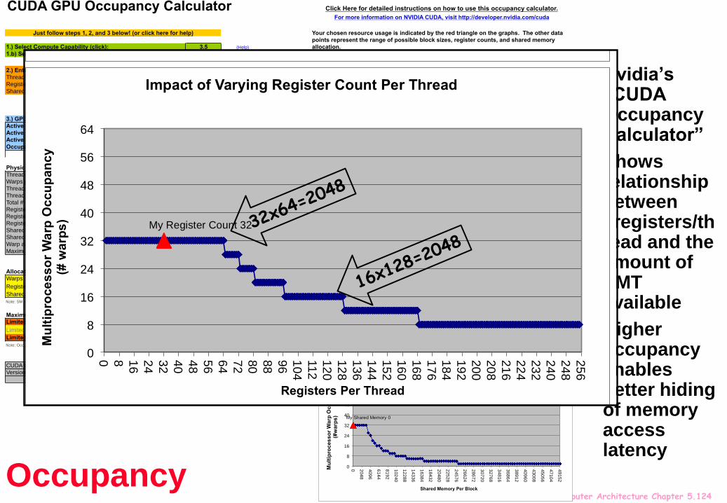
Nvidia’s “CUDA Occupancy Calculator”
Shows relationship between #registers/thread and the amount of SMT available
Higher occupancy enables better hiding of memory access latency
CUDA GPU Occupancy Calculator
1.) Select Compute Capability (click): 3.5 (Help)
1.b) Select Shared Memory Size Config (bytes) 49152
2.) Enter your resource usage:
Threads Per Block 64 (Help)
Registers Per Thread 32
Shared Memory Per Block (bytes) 0
(Don't edit anything below this line)
3.) GPU Occupancy Data is displayed here and in the graphs:
Active Threads per Multiprocessor 1024 (Help)
Active Warps per Multiprocessor 32
Active Thread Blocks per Multiprocessor 16
Occupancy of each Multiprocessor 50%
Physical Limits for GPU Compute Capability: 3.5
Threads per Warp 32
Warps per Multiprocessor 64
Threads per Multiprocessor 2048
Thread Blocks per Multiprocessor 16
Total # of 32-bit registers per Multiprocessor 65536
Register allocation unit size 256
Register allocation granularity warp
Registers per Thread 255
Shared Memory per Multiprocessor (bytes) 49152
Shared Memory Allocation unit size 256
Warp allocation granularity 4
Maximum Thread Block Size 1024
Allocated Resources Per Block Limit Per SM
= Allocatable
Blocks Per SM
Warps (Threads Per Block / Threads Per Warp) 2 64 16
Registers (Warp limit per SM due to per-warp reg count) 2 64 32
Shared Memory (Bytes) 0 49152 16
Note: SM is an abbreviation for (Streaming) Multiprocessor
Maximum Thread Blocks Per Multiprocessor Blocks/SM * Warps/Block = Warps/SM
Limited by Max Warps or Max Blocks per Multiprocessor 16 2 32
Limited by Registers per Multiprocessor 32 2 0
Limited by Shared Memory per Multiprocessor 16 2 32
Note: Occupancy limiter is shown in orange
CUDA Occupancy Calculator
Version: 5.1
Threads Warps/Multiprocessor Registers Warps/Multiprocessor Shared MemoryWarps/Multiprocessor
64 32 32 32 0 32
32 16 1 32 0 32
64 32 2 32 512 32
96 48 3 32 1024 32
128 64 4 32 1536 32
160 60 5 32 2048 32
192 60 6 32 2560 32
224 63 7 32 3072 32
256 64 8 32 3584 26
288 63 9 32 4096 24
320 60 10 32 4608 20
352 55 11 32 5120 18
384 60 12 32 5632 16
416 52 13 32 6144 16
448 56 14 32 6656 14
480 60 15 32 7168 12
512 64 16 32 7680 12
544 51 17 32 8192 12
576 54 18 32 8704 10
608 57 19 32 9216 10
640 60 20 32 9728 10
Click Here for detailed instructions on how to use this occupancy calculator.
For more information on NVIDIA CUDA, visit http://developer.nvidia.com/cuda
Copyright and License
Just follow steps 1, 2, and 3 below! (or click here for help)
Physical Max Warps/SM = 64
Occupancy = 32 / 64 = 50%
Your chosen resource usage is indicated by the red triangle on the graphs. The other data
points represent the range of possible block sizes, register counts, and shared memory
allocation.
My Block Size 64
0
8
16
24
32
40
48
56
64
0 64 128 192 256 320 384 448 512 576 640 704 768 832 896 960 1024
Mu
ltip
roce
sso
r W
arp
Occu
pa
nc
y
(# w
arp
s)
Threads Per Block
Impact of Varying Block Size
My Register Count 32
0
8
16
24
32
40
48
56
64
0
8
16
24
32
40
48
56
64
72
80
88
96
10
4
11
2
12
0
12
8
13
6
14
4
15
2
16
0
16
8
17
6
18
4
19
2
20
0
20
8
21
6
22
4
23
2
24
0
24
8
25
6
Mu
ltip
roce
sso
r W
arp
Occu
pan
cy
(# w
arp
s)
Registers Per Thread
Impact of Varying Register Count Per Thread
My Shared Memory 0
0
8
16
24
32
40
48
56
64
0
20
48
40
96
61
44
81
92
10
240
12
288
14
336
16
384
18
432
20
480
22
528
24
576
26
624
28
672
30
720
32
768
34
816
36
864
38
912
40
960
43
008
45
056
47
104
49
152
Mu
ltip
roces
so
r W
arp
Occu
pa
nc
y
(#w
arp
s)
Shared Memory Per Block
Impact of Varying Shared Memory Usage Per Block
Occupancy
CUDA GPU Occupancy Calculator
1.) Select Compute Capability (click): 3.5 (Help)
1.b) Select Shared Memory Size Config (bytes) 49152
2.) Enter your resource usage:
Threads Per Block 64 (Help)
Registers Per Thread 32
Shared Memory Per Block (bytes) 0
(Don't edit anything below this line)
3.) GPU Occupancy Data is displayed here and in the graphs:
Active Threads per Multiprocessor 1024 (Help)
Active Warps per Multiprocessor 32
Active Thread Blocks per Multiprocessor 16
Occupancy of each Multiprocessor 50%
Physical Limits for GPU Compute Capability: 3.5
Threads per Warp 32
Warps per Multiprocessor 64
Threads per Multiprocessor 2048
Thread Blocks per Multiprocessor 16
Total # of 32-bit registers per Multiprocessor 65536
Register allocation unit size 256
Register allocation granularity warp
Registers per Thread 255
Shared Memory per Multiprocessor (bytes) 49152
Shared Memory Allocation unit size 256
Warp allocation granularity 4
Maximum Thread Block Size 1024
Allocated Resources Per Block Limit Per SM
= Allocatable
Blocks Per SM
Warps (Threads Per Block / Threads Per Warp) 2 64 16
Registers (Warp limit per SM due to per-warp reg count) 2 64 32
Shared Memory (Bytes) 0 49152 16
Note: SM is an abbreviation for (Streaming) Multiprocessor
Maximum Thread Blocks Per Multiprocessor Blocks/SM * Warps/Block = Warps/SM
Limited by Max Warps or Max Blocks per Multiprocessor 16 2 32
Limited by Registers per Multiprocessor 32 2 0
Limited by Shared Memory per Multiprocessor 16 2 32
Note: Occupancy limiter is shown in orange
CUDA Occupancy Calculator
Version: 5.1
Threads Warps/Multiprocessor Registers Warps/Multiprocessor Shared MemoryWarps/Multiprocessor
64 32 32 32 0 32
32 16 1 32 0 32
64 32 2 32 512 32
96 48 3 32 1024 32
128 64 4 32 1536 32
160 60 5 32 2048 32
192 60 6 32 2560 32
224 63 7 32 3072 32
256 64 8 32 3584 26
288 63 9 32 4096 24
320 60 10 32 4608 20
352 55 11 32 5120 18
384 60 12 32 5632 16
416 52 13 32 6144 16
448 56 14 32 6656 14
480 60 15 32 7168 12
512 64 16 32 7680 12
544 51 17 32 8192 12
576 54 18 32 8704 10
608 57 19 32 9216 10
640 60 20 32 9728 10
Click Here for detailed instructions on how to use this occupancy calculator.
For more information on NVIDIA CUDA, visit http://developer.nvidia.com/cuda
Copyright and License
Just follow steps 1, 2, and 3 below! (or click here for help)
Physical Max Warps/SM = 64
Occupancy = 32 / 64 = 50%
Your chosen resource usage is indicated by the red triangle on the graphs. The other data
points represent the range of possible block sizes, register counts, and shared memory
allocation.
My Block Size 64
0
8
16
24
32
40
48
56
64
0 64 128 192 256 320 384 448 512 576 640 704 768 832 896 960 1024
Mu
ltip
roces
so
r W
arp
Occu
pa
nc
y
(# w
arp
s)
Threads Per Block
Impact of Varying Block Size
My Register Count 32
0
8
16
24
32
40
48
56
64
0
8
16
24
32
40
48
56
64
72
80
88
96
10
4
11
2
12
0
12
8
13
6
14
4
15
2
16
0
16
8
17
6
18
4
19
2
20
0
20
8
21
6
22
4
23
2
24
0
24
8
25
6
Mu
ltip
roce
sso
r W
arp
Occu
pan
cy
(# w
arp
s)
Registers Per Thread
Impact of Varying Register Count Per Thread
My Shared Memory 0
0
8
16
24
32
40
48
56
64
0
20
48
40
96
61
44
81
92
10
240
12
288
14
336
16
384
18
432
20
480
22
528
24
576
26
624
28
672
30
720
32
768
34
816
36
864
38
912
40
960
43
008
45
056
47
104
49
152
Mu
ltip
roces
so
r W
arp
Occu
pa
nc
y
(#w
arp
s)
Shared Memory Per Block
Impact of Varying Shared Memory Usage Per Block

Advanced Computer Architecture Chapter 5.125
We have explored:Pipeline parallelism
Dynamic instruction scheduling
Static instruction scheduling
Multiple instructions per cycle
Very long instruction words (VLIW)
SIMT – single-instruction multiple thread – and how it maps onto SIMD
Multi-threading
Coarse-grain
Fine-grain
Simultaneous multithreading (SMT)
Statically-partitioned multithreading
Vector instructions and SIMD – coming soon
Chapter summary

Advanced Computer Architecture Chapter 5.126
Extra slides for interest/funIs the “minimum” operator associative?
min(min(X, Y), Z = min(X, min(Y, Z)) ?
min(X, Y) = if X<Y then X else Y
min(min(10, x), 100) = 100

Advanced Computer Architecture Chapter 5.127
Extra slides for interest/funIs the “minimum” operator associative?
min(min(X, Y), Z = min(X, min(Y, Z)) ?
min(X, Y) = if X<Y then X else Y
All comparisons on NaNs always fail….
min(min(10, NaN), 100) = 100

Advanced Computer Architecture Chapter 5.128
Extra slides for interest/funIs the “minimum” operator associative?
min(min(X, Y), Z = min(X, min(Y, Z)) ?
min(X, Y) = if X<Y then X else Y
All comparisons on NaNs always fail….
min(X , NaN) = NaN
min(NaN, Y ) = Y
min(min(X , NaN), Y ) = min(NaN, Y ) = Y
min(X,min(NaN,Y)) = min(X,Y)
min(min(10, NaN), 100) = 100

Advanced Computer Architecture Chapter 5.129
Associativity in floating point(a+b)+c = a+(b+c) ?
Example: Consider 3-digit base-10 floating-point
1+1+1+1+1+1+1+1+…..+1+1+1+1+1+1+1+1+1+1+1+1000
1000+1+1+1+1+1+1+1+1+…..+1+1+1+1+1+1+1+1+1+1+1+1
Consequence: many compilers use loop unrolling and reassociation to enhance parallelism in summations
And results are different!
But you can tell the compiler not to, eg:
“–fp-model precise” with Intel’s compilers
1000 ones
1000 ones
(What’s the right way to sum an array? Seehttp://en.wikipedia.org/wiki/Kahan_summation_algorithm)