instruction booklet ib158002en eaton spd max series …pub/@electrical/... · instruction booklet...
TRANSCRIPT

ContentsDescription Page
1.0 Introduction . . . . . . . . . . . . . . . . . . . . . . . . . . . 22.0 Installation . . . . . . . . . . . . . . . . . . . . . . . . . . . . 33.0 Operating Features . . . . . . . . . . . . . . . . . . . . . 64.0 Troubleshooting . . . . . . . . . . . . . . . . . . . . . . . . 85.0 Specifications . . . . . . . . . . . . . . . . . . . . . . . . . 96.0 Ordering Guidelines . . . . . . . . . . . . . . . . . . . . 107.0 Warranty . . . . . . . . . . . . . . . . . . . . . . . . . . . . 16
Effective October 2014Instruction Booklet IB158002EN
Eaton SPD Max SeriesSurge Protective Device

2
Instruction Booklet IB158002ENEffective October 2014
Eaton SPD Max SeriesSurge Protective Device
EATON www.eaton.com
1.0 Introduction1.1 Manual Organization
This Installation Manual describes the safe installation and operation of the Eaton® SPD Max Series Surge Protective Device (SPD).
This manual is organized into seven sections, as follows:
1.0 Introduction2.0 Installation3.0 Operating Features4.0 Troubleshooting5.0 Specifications6.0 Ordering Guidelines7.0 Warranty
1.2 Product Overview
The Eaton SPD Max Series protects critical electrical and electronic equipment including switchgear, switchboards, panelboards and other types of enclosures from damage by voltage transients and surges. This is done by shunting high energy lightning surges (and other transient disturbances) away from the equipment being pro-tected. It does this in nanoseconds by providing a low impedance surge path to ground while supporting power frequency voltage.
The Eaton SPD Max Series is designed to mount on the wall (or other vertical surface) as close as possible to the electrical cabinet. The SPD Max Series is available in voltage ratings from 120-600V AC, surge current capacity ratings from 100kA to 800kA, and NEMA 4 or NEMA 4X enclosures.
The Eaton SPD Max Series is available in two feature packages (Basic and Standard with Surge Counter), as described in Section 3, Operating Features. Each model is available in Delta, Wye, and Split Phase wiring configurations.
All Eaton SPD Max Series models have been tested and certified by Underwriter’s Laboratory (UL®), to comply with UL Standard 1449, 3rd Edition, UL Standard 1283 5th Edition, CSA 22.2 and CSA Electrical Notice NO. 516 Edition 1.
1.3 Safety Precautions
A licensed/qualified electrician must complete all instructions in this manual in accordance with the National Electric Code (NEC®), Canadian Electrical Code (CEC), state, and local codes, or other applicable country codes. All applicable local electrical codes super-sede these instructions.
WARNINGIMPROPER INSTALLATION COULD CAUSE DEATH, INJURY AND EQUIPMENT DAMAGE. FOLLOW ALL WARNINGS AND CAUTIONS. COMPLETELY READ AND UNDERSTAND THE INFORMATION IN THIS INSTRUCTION MANUAL BEFORE ATTEMPTING TO INSTALL OR OPERATE THIS EQUIPMENT. IMPROPER WIRING COULD CAUSE DEATH, INJURY AND/ OR EQUIPMENT DAMAGE. ONLY LICENSED/QUALIFIED ELECTRICIANS WHO ARE TRAINED IN THE INSTALLATION AND SERVICE OF ELECTRICAL SERVICES ARE TO INSTALL AND SERVICE THIS EQUIPMENT HAZARDOUS VOLTAGES ARE PRESENT INSIDE THE SPD DURING NORMAL OPERATION. FOLLOW ALL SAFE WORK PRACTICES TO AVOID ELECTRICAL SHOCK.
WARNINGARC FLASH DURING INSTALLATION COULD CAUSE INJURY OR DEATH. USE APPROPRIATE SAFETY PRECAUTIONS AND EQUIPMENT FOR ARC FLASH PROTECTION.
1.4 Catalog Numbering System
Each Eaton SPD Max Series unit has a name plate that identifies the parameters used for manufacture. These parameters are expressed in letters and numbers, to reflect the Series, kA Rating, Voltage Code, Feature Package, and Application, as shown in Table 1 and Table 5.
Table 1. Catalog Numbering System
SPM 250 480D 3 R
Series Voltage Code Application
kA Rating Feature Package
For example, a 480 volt Delta (3-wire plus Ground) for use in a NEMA 4 application requires an SPD model SPM250480D2R, where:
SPM = SPD Max Series,
250 = the kA rating (100 – 800 kA),
480D = the voltage,
3 = the feature package (Standard With Surge Counter),
R = the Application Suffix (NEMA 4 with internal disconnect).
These numbers appear as part of the product label attached to the side of the SPD Max enclosure. See Figure 1.
Figure 1. Product Label

3
Instruction Booklet IB158002ENEffective October 2014
Eaton SPD Max SeriesSurge Protective Device
EATON www.eaton.com
1.5 Equipment Testing
WARNINGCONDUCTING DIELECTRIC, MEGGER, OR HI-POTENTIAL TESTING WITH THE SPD INSTALLED WILL CAUSE INTERNAL DAMAGE TO THE SPD. THE SPD WILL ALSO CAUSE THE TEST TO FAIL.
Every Eaton SPD Max Series unit is tested at the factory for dielec-tric breakdown. No further SPD testing is required for installation.
If you desire to test distribution equipment by performing dielectric, megger, or hi-potential tests, any installed SPD must be discon-nected from the power distribution system to prevent damage to the unit.
Follow this procedure to safely disconnect the SPD:
1. For SPDs connected to a circuit breaker or fuse:a. 3-wire Delta SPDs: Turn off the circuit breaker or remove the
fuses from the fuse holder to isolate the SPD.
b. Wye and Split phase SPDs: Turn off the circuit breaker or remove the fuses from the fuse holder to isolate the SPD and remove the Neutral connection on Wye SPDs.
2.0 Installation
WARNINGINSTALLING AN SPD THAT IS IMPROPERLY RATED FOR THE ELECTRICAL SYSTEM VOLTAGE COULD CREATE A POTENTIALLY HAZARDOUS CONDITION, RESULTING IN INJURY OR EQUIPMENT DAMAGE.
2.1 Preparation for Installation
CAUTIONEATON SPD SERIES PRODUCTS MUST BE INSTALLED OR REPLACED BY A QUALIFIED ELECTRICIAN TO AVOID INJURY OR EQUIPMENT DAMAGE.
Before installing an Eaton SPD Max Series unit, do the following:
• Verify that the area is clear of any dirt, debris or clutter that may hamper the installation process.
• Verify that there is enough space to install the SPD. See Figure 17 for dimensions.
• Confirm that all tools and equipment needed for the installation are available.
• Confirm that the system voltage and wiring configuration is the same as the SPD you are installing. Check the voltage rating label on the side of the SPD.
WARNINGTURN OFF THE POWER SUPPLY BEFORE WORKING IN ANY ELECTRICAL CABINET OR ON ANY CIRCUIT BREAKER PANEL. FAILURE TO DO SO COULD RESULT IN INJURY OR DEATH FROM ELECTRICAL SHOCK
NOTICEA POOR GROUND, OR GROUNDING/BONDING VIOLATIONS, COULD PREVENT THE SPD FROM PERFORMING AS SPECIFIED. DO NOT USE THE SPD TO CARRY OR PASS THROUGH GROUND TO OTHER DEVICES OR LEADS. DAMAGE TO THE EQUIPMENT MAY RESULT.
• Check the facility grounding system. All grounding, bonding, and earthing must meet the NEC, CEC and any other national, state and local electrical codes.
• An insulated grounding conductor that is identical in size and insulation material and thickness to the grounded and ungrounded circuit supply conductors, except that it is green with or without one or more yellow stripes, is to be installed as part of the circuit that supplies the SPD Max Series unit.
• Refer to Table 250-122 of the NEC to select the appropriate size of the grounding conductor. This grounding conductor is to be grounded to earth at the service equipment or other acceptable building earth ground such as the building frame in the case of a high steel-frame structure.
• Any attachment-plug receptacles in the vicinity of the SPD Max Series unit are to be of a grounding type, and the grounding con-ductors serving these receptacles are to be connected to earth ground at the service equipment or other acceptable building earth ground such as the building frame in the case of a high-rise steel-frame structure.
• Pressure terminal or pressure slicing connectors and soldering lugs used in the installation of the SPD Max Series unit shall be identified as being suitable for the material of the conductors. Conductors of dissimilar metals shall not be intermixed in a termi-nal or splicing connector where physical contact occurs between dissimilar conductors unless the device is identified for the pur-pose and conditions of use.
2.2 Installation Locations
Eaton’s SPD Max Series can be installed next to, above, or below any existing electrical enclosure.
The ideal mounting location for the Eaton SPD Max Series is as close as possible to the electrical enclosure and should be mounted in such a way as to minimize the cable length and eliminate any sharp bends in the wiring conduit.

4
Instruction Booklet IB158002ENEffective October 2014
Eaton SPD Max SeriesSurge Protective Device
EATON www.eaton.com
2.3 Installation Procedures
1. Before mounting the SPD Max Series device ensure that the mounting surface is sufficient to support the weight of the SPD. See Section 5.0 Specifications for weight. The SPD should be mounted as close as possible to the electrical cabinet and as close as possible to the wiring connection point within the electrical cabinet. This will ensure a minimum wire length and maximum SPD performance. Preferred entry of the incoming power is on the hinge side of the enclosure. This location offers the best VPR ratings. Top and bottom entry is also available. If the user chooses to wire the entry cable through the top of the enclosure the internally mounted terminal block for the neutral (if equipped) and ground connections must be moved to the bottom of the enclosure. See Section 2.3.1 Installation Procedures for Top Entry. The three possible power entry locations are identified on the enclosure with a dimple located on the top, bottom and hinge side of the enclosure housing (see Figure 16).
Table 2. Suggested Entry Cable and Conduit Hub Sizes
Power entry into enclosure
Max. – Min. Entry Cable AWG Max. Trade size Hub
Top 1/0 – 10 AWG 1 ½”
Hinge Side 1/0 – 10 AWG 2”
Bottom 1/0 – 10 AWG 1 ½”
2. Layout the four enclosure mounting holes using the enclosure dimensions provided in Figure 16. Drill the appropriate holes per the product dimensions.
Figure 2. Typical Form C Wiring Connections
3. Determine the correct metal conduit for phase wires using Table 2 and install onto the SPD enclosure. If using the Form C contacts route Form C wires through a separate maximum ¾ inch trade size hub and conduit.*
4. Determine the hole location on the receiving electrical enclosure and either remove the knock-out provided or drill the appropriate size hole at that location.
5. Select the correct wiring diagram for the SPD Max you are install-ing. Refer to the wiring diagrams in Figures 8-15
6. Determine the wire gauge and length required to make the SPD phase connections and cut the wires to the appropriate length. (To maximize SPD performance, wire length should be as short as possible). Connect the Phase wires through the metal conduit.
otee:N Wires should not exceed the allowable bend radius according to NEC and CEC during installation. Route all Phase, Ground and Neutral (where applicable) wires through conduit. Route Form C wires (where applicable) through a separate max. 3/4 inch trade size hub and conduit.*
7. Determine the wire length for the Ground and Neutral (where applicable) wires and cut these wires as needed. Again, keep these wires as short as possible to maximize SPD performance and don’t exceed the bend radius of the wire during installation.
8. Standard with Surge Counter devices also provide wiring for Form C relay contacts. This connection can be used for remote monitoring of the SPD. The Form C contacts are rated max 0.46 A, 150 Vac, 1A, 30 Vdc.* Note: when a SPD Max contains two SPD modules the user can connect their Form C wires to either SPD1 or SPD2. There is no need to wire to both units as they are wired together through the SPD Status board and two ribbon cables. (See Figure 2). Follow all national, state and local electri-cal codes when making these connections.
*Notee: Utilization of Form C contacts is optional. Connection is not mandatory for the operation of the SPD.

5
Instruction Booklet IB158002ENEffective October 2014
Eaton SPD Max SeriesSurge Protective Device
EATON www.eaton.com
2.3.1 Installation Procedures for Top Entry
If bottom or side entry isn’t practical for the installation of the SPD Max, top entry can be accomplished using the following steps.
Figure 3. SPD Max with Two SPDs and Circuit Breaker
1. Open the front door of the SPD Max by loosening, but not removing, the 7 latches that secure the door to the base of the enclosure. See Figure 3.
2. To gain access to the wire termination compartment the display cable for a single brick, SPD1, must be unplugged. If the SPD Max contains two SPDs, SPD1 and SPD2, the display cable and two SPD Status ribbon cables must be unplugged. In either case, this is done by loosening the two Cable Hold Down Bracket screws ~ 1/2 turn and sliding the bracket(s) up to gain access to the ribbon cable connectors(s). Using a pair of long nosed pliers carefully unplug the display cable and SPD Status cable connectors from the SPDs, if they are equipped. See Figure 3.
3. Remove the four Torx® screws holding down the hinged dead front panels. Swing open the hinged dead front panels to access the wiring compartments.
4. Remove the white neutral wire(s) from the neutral terminal block and the SPD(s) and discard them. (See Figure 4)
Display CableLid Latches
Cable Hold Down Brackets
Lid Latches
Lid LatchesSPD Status Cables
SPD Status
Figure 4. Standard with Surge Counter Feature Package Display

6
Instruction Booklet IB158002ENEffective October 2014
Eaton SPD Max SeriesSurge Protective Device
EATON www.eaton.com
3.0 Operating Features3.1 General
The Eaton SPD Max Series comes in two feature packages: Basic, and Standard with Surge Counter. The operating specifics of each feature package are described below.
The Eaton SPD Max Series requires no operator involvement other than to monitor the display panel or the audible alarm (if equipped) to determine status of the SPD(s).
After system power is applied, the SPD automatically begins protect-ing downstream electrical equipment from voltage transients and surges.
Some SPD Max Series units have a Form C relay contact that allows for the remote indication of SPD status. Wiring of the Form C con-tacts is not mandatory for the operation of the SPD Max Series device.
3.2 Displays and Indicators
All Eaton SPD Max Series units (Basic, and Standard with Surge Counter) use a display panel to indicate system status. The display panel is slightly different for each feature package.
Each display has both green and red light emitting diodes (LEDs) to indicate the status of the protection on each phase. Green indicates the phase is fully protected. Red indicates a loss of protection. Wye, Split Phase and High-Leg Delta units have an additional set of green/ red LEDs to indicate status of Neutral/Ground protection.
When the LED(s) turn red, an audible alarm will also sound if equipped with a Standard with Surge Counter display.
Specific operating conditions displayed for each Eaton SPD Max Series Feature Package is described below.
3.2.1 Basic Feature Package
The Eaton SPD Max Series Basic Feature display is shown in Figure 6.
Figure 6. Basic Feature Package Display
5. Unscrew the Neutral and Ground terminal blocks from the enclo-sure base. Rotate the Ground terminal block 180o and mount the two terminal blocks in the mounting holes located on the bottom left of the unit. (See Figure 5)
Figure 5. Neutral and Ground Terminal Block re-located for Top Entry Wire Installation
6. Cut #10 AWG neutral wire(s) to fit from the relocated neutral ter-minal block to the individual SPD(s) keeping the wires as short as possible.
7. Attach a #10 AWG ring terminal to one end of the new neutral wire(s) and a #10 AWG ferrule to the other end.
8. Connect the ring terminal end of the new neutral wire(s) to the SPD neutral connection and the ferrule end of the wire to the re-located neutral block.
9. Tighten the neutral terminal block screws with a torque of 50 in-lbs.
10. Tighten either SPD1 or SPD2 neutral connection with a torque of 36 in-lbs, which is molded into the SPD plastic enclosure.
11. Up to a 1 1/2 NPT conduit punch can be used to access the top of the enclosure. Use the dimple located on the enclosure wall to center the hole. Install proper conduit hub, NEMA 4 or NEMA 4X.
12. Optional Form C wiring - If using a remote monitoring Form C relay, locate the dimples on the top or bottom of the enclosure for centering the cut-out hole for conduit installation. Maximum conduit size of 3/4 NPT for Form C wires.
13. Mount SPD Max unit in desired location as close as possible to equipment to be protected. Feed wire sizes #10 - 1/0 AWG into the unit and terminate them per wiring diagram located on the inside enclosure lid or the instruction manual. Optional Form C Relay - Install remote monitoring Form C relay wiring, if needed, into one SPD. Either SPD can be used if two are present, but it’s only necessary to connect to one SPD device within the enclo-sure.
14. Swing hinged dead front panels closed and re-install the four Torx® screws to secure the dead front panels.
15. Re-attach all ribbon cable connectors and slide Cable Hold Down Brackets back into place and tighten screws to 5 Lb - In.
16. Close and secure the seven enclosure lid latches.
Re-located Terminal Blocks
7
Instruction Booklet IB158002ENEffective October 2014
Eaton SPD Max SeriesSurge Protective Device
EATON www.eaton.com
The Basic Feature Package has the following features: • Green LEDs: Illumination indicates the phase is fully protected,
and operating normally, with all protection active and available. Green LEDs also indicate Neutral to Ground protection on units with a Neutral wire. Green LEDs do not indicate on/off status of power.
• Red LEDs: Illumination indicates a loss of protection, and that one or more protective devices are now inactive and unavailable for that Phase. Red LEDs also indicate Neutral to Ground protection on units with a Neutral wire. Red LEDs do not indicate on/off sta-tus of power.
3.2.2 Standard With Surge Counter Feature Package
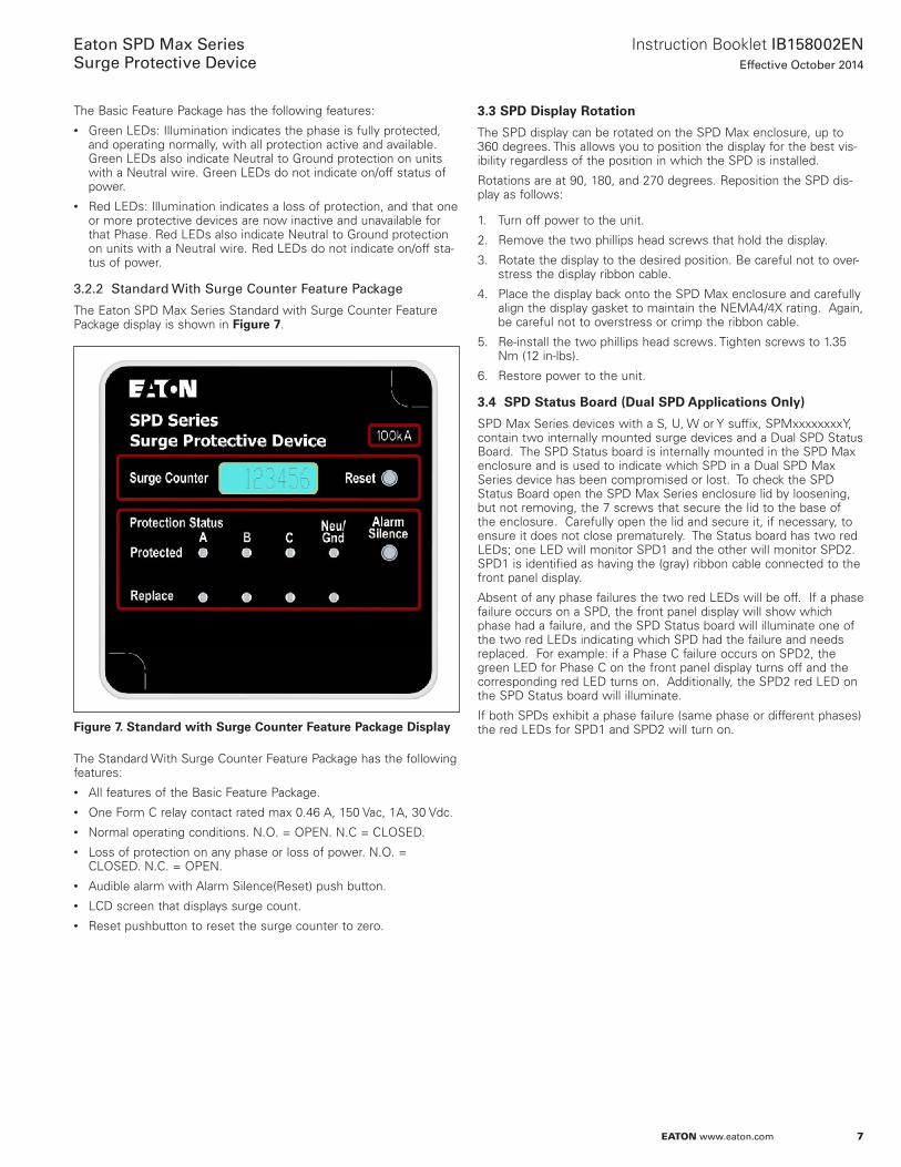
The Eaton SPD Max Series Standard with Surge Counter Feature Package display is shown in Figure 7.
Figure 7. Standard with Surge Counter Feature Package Display
The Standard With Surge Counter Feature Package has the following features:• All features of the Basic Feature Package.• One Form C relay contact rated max 0.46 A, 150 Vac, 1A, 30 Vdc.• Normal operating conditions. N.O. = OPEN. N.C = CLOSED.• Loss of protection on any phase or loss of power. N.O. =
CLOSED. N.C. = OPEN.• Audible alarm with Alarm Silence(Reset) push button.• LCD screen that displays surge count.• Reset pushbutton to reset the surge counter to zero.
3.3 SPD Display Rotation
The SPD display can be rotated on the SPD Max enclosure, up to 360 degrees. This allows you to position the display for the best vis-ibility regardless of the position in which the SPD is installed.
Rotations are at 90, 180, and 270 degrees. Reposition the SPD dis-play as follows:
1. Turn off power to the unit.
2. Remove the two phillips head screws that hold the display.
3. Rotate the display to the desired position. Be careful not to over-stress the display ribbon cable.
4. Place the display back onto the SPD Max enclosure and carefully align the display gasket to maintain the NEMA4/4X rating. Again, be careful not to overstress or crimp the ribbon cable.
5. Re-install the two phillips head screws. Tighten screws to 1.35 Nm (12 in-lbs).
6. Restore power to the unit.
3.4 SPD Status Board (Dual SPD Applications Only)
SPD Max Series devices with a S, U, W or Y suffix, SPMxxxxxxxxY, contain two internally mounted surge devices and a Dual SPD Status Board. The SPD Status board is internally mounted in the SPD Max enclosure and is used to indicate which SPD in a Dual SPD Max Series device has been compromised or lost. To check the SPD Status Board open the SPD Max Series enclosure lid by loosening, but not removing, the 7 screws that secure the lid to the base of the enclosure. Carefully open the lid and secure it, if necessary, to ensure it does not close prematurely. The Status board has two red LEDs; one LED will monitor SPD1 and the other will monitor SPD2. SPD1 is identified as having the (gray) ribbon cable connected to the front panel display.
Absent of any phase failures the two red LEDs will be off. If a phase failure occurs on a SPD, the front panel display will show which phase had a failure, and the SPD Status board will illuminate one of the two red LEDs indicating which SPD had the failure and needs replaced. For example: if a Phase C failure occurs on SPD2, the green LED for Phase C on the front panel display turns off and the corresponding red LED turns on. Additionally, the SPD2 red LED on the SPD Status board will illuminate.
If both SPDs exhibit a phase failure (same phase or different phases) the red LEDs for SPD1 and SPD2 will turn on.
8
Instruction Booklet IB158002ENEffective October 2014
Eaton SPD Max SeriesSurge Protective Device
EATON www.eaton.com
4.0 TroubleshootingMany SPD failures result from improper installation. Once the SPD is installed properly, it is a highly reliable unit. The most common rea-son for SPD failure is a temporary overvoltage (TOV) condition.
If the SPD does not function properly, first confirm that it is installed properly. See Section 2, Installation.
If the SPD malfunctions after it has been operating routinely, refer to Table 3, Troubleshooting Chart. This Troubleshooting Chart identifies possible causes and solutions to the malfunction. Further assistance may be obtained by calling Eaton’s Technical Resource Center (TRC) and speaking to a Surge Protection Application Engineer, at 1-800-809-2772, option 4, sub-option 2, including being directed to the warranty process if applicable.
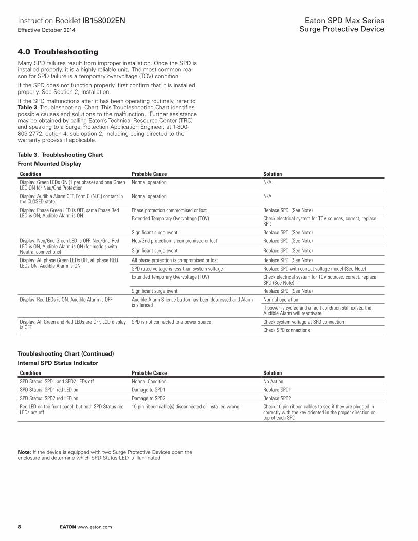
Table 3. Troubleshooting Chart
Front Mounted Display
Condition Probable Cause Solution
Display: Green LEDs ON (1 per phase) and one Green LED ON for Neu/Gnd Protection
Normal operation N/A.
Display: Audible Alarm OFF, Form C (N.C.) contact in the CLOSED state
Normal operation N/A
Display: Phase Green LED is OFF, same Phase Red LED is ON, Audible Alarm is ON
Phase protection compromised or lost Replace SPD (See Note)
Extended Temporary Overvoltage (TOV) Check electrical system for TOV sources, correct, replace SPD
Significant surge event Replace SPD (See Note)
Display: Neu/Gnd Green LED is OFF, Neu/Gnd Red LED is ON, Audible Alarm is ON (for models with Neutral connections)
Neu/Gnd protection is compromised or lost Replace SPD (See Note)
Significant surge event Replace SPD (See Note)
Display: All phase Green LEDs OFF, all phase RED LEDs ON, Audible Alarm is ON
All phase protection is compromised or lost Replace SPD (See Note)
SPD rated voltage is less than system voltage Replace SPD with correct voltage model (See Note)
Extended Temporary Overvoltage (TOV) Check electrical system for TOV sources, correct, replace SPD (See Note)
Significant surge event Replace SPD (See Note)
Display: Red LEDs is ON. Audible Alarm is OFF Audible Alarm Silence button has been depressed and Alarm is silenced
Normal operation
If power is cycled and a fault condition still exists, the Audible Alarm will reactivate
Display: All Green and Red LEDs are OFF, LCD display is OFF
SPD is not connected to a power source Check system voltage at SPD connection
Check SPD connections
Troubleshooting Chart (Continued)
Internal SPD Status Indicator
Condition Probable Cause Solution
SPD Status: SPD1 and SPD2 LEDs off Normal Condition No Action
SPD Status: SPD1 red LED on Damage to SPD1 Replace SPD1
SPD Status: SPD2 red LED on Damage to SPD2 Replace SPD2
Red LED on the front panel, but both SPD Status red LEDs are off
10 pin ribbon cable(s) disconnected or installed wrong Check 10 pin ribbon cables to see if they are plugged in correctly with the key oriented in the proper direction on top of each SPD
otee:N If the device is equipped with two Surge Protective Devices open the enclosure and determine which SPD Status LED is illuminated

9
Instruction Booklet IB158002ENEffective October 2014
Eaton SPD Max SeriesSurge Protective Device
EATON www.eaton.com
5.0 Specifications
Table 4. Specifications
Description Specification
Surge current capacity per phase 100, 120, 160, 200, 250, 300, 320, 400, 600, 800 kA ratings available
Nominal discharge current (In) 20kA
Short circuit current rating (SCCR) 200kA
SPD Type Basic feature package = Type 1 (can also be used in Type 2 applications)
Standard with Surge Counter feature package = Type 2
Enclosure Types NEMA 4, NEMA 4X Enclosure
Circuit Breaker - 30 Amp Eaton Catalog Number: FDC3030L
Circuit Breaker Load and Line
Terminal Torque Specifications #10AWG 35 Lb-in; #8AWG 40Lb-in; #6 - #4AWG 45 Lb-in; #3 - I/0 AWG 50 Lb-in. (SPD Max Wire Range #10 - 1/0 AWG)
Standard split phase voltages available 120/240
Single phase 230
Three phase wye system voltages available 120/208, 127/220, 230/400, 277/480, 347/600
Three phase delta system voltages 240, 480, 600
Three phase high leg delta system voltages 120/240 high leg phase wire will be identified with a tag from the factory.
Input Power Frequency 50/60 Hz
Power consumption (Standard with Surge Counter units)
208Y, 220Y, 230L, 240S, 240D, and 240H voltage codes 0.6W
400Y, 480Y, and 480D Basic voltage codes 1.7W
600Y and 600D voltage codes 2.1W
Protection modes Single split phase L-N, L-G, N-G, L-L, Single phase L-N, L-G, N-G, Three phase delta..L-G, L-L , Three phase Wye.L-N, L-G, N-G, L-L, Three phase high leg delta L-N, L-G, N-G, L-L
Maximum continuous operating voltage (MCOV)
230V Single Phase 320V L-N, 320V L-G, 320V N-G
127V/220V WYE, 120V/240V Single Split Phase 150V L-N, 150V L-G, 150V N-G, 300V L-L
120V/240V Hi Leg 150V L-N, 150V L-G, 150V N-G, 300V L-L, 320V H-N, 320V H-G, 470V H-L
230V/400V WYE, 277/480V WYE 320V L-N, 320V L-G, 320V N-G, 640V L-L
347V/600V WYE 420V L-N, 420V L-G, 420V N-G, 840V L-L
240V DELTA 300V L-G, 300V L-L
480V DELTA 640V L-G, 640V L-L
600V DELTA 840V L-G, 840V L-L
Ports 1 or 2
Operating temperature & humidity -20 through 50° C (-4 through 122° F), 5% through 95%, non-condensing
Storage temperature -20 through 50° C (-4 through 122° F)
Operating Altitude Up to 16,000 ft (5000m)
Weight Not to exceed 52 lbs
Form C relay contact ratings Max 0.46 A, 150 Vac, 1A, 30 Vdc
Form C terminal block ratings Rated 300V, 16A, 30-12 AWG solid or stranded wire. Torque range 5-7 lbs-in
Form C relay contact logic Power on, normal state - NO contact = OPEN, NC contact = CLOSED Power off, fault state, - NO contact = CLOSED, NC contact = OPEN
EMI/RFI filtering attenuation (Standard With Surge Counter) Up to 50 dB from 10 kHz to 100 MHz
Standards / Agency Certifications UL1449 Edition 3 – Std for Surge Protective Devices
UL1283 Edition 5 – Std for EMI Filters (Type 2 SPDs only)
CSA Electrical Notice NO. 516 Edition 1 – Surge/Transient Voltage Suppressor (excludes 230L voltage code)
CSA 22.2 NO. 8-M1986 Edition 4 – EMI Filters
Warranty 15 years from the date of delivery to the purchaser, 20 years if the product is properly registered at www.eaton.com/spd
RoHS Compliant Yes

10
Instruction Booklet IB158002ENEffective October 2014
Eaton SPD Max SeriesSurge Protective Device
EATON www.eaton.com
6.0 Ordering Guidelines
Table 5. Eaton SPD Max Series
SPM
kA Rating Options
100kA Per Phase120kA Per Phase160kA Per Phase200kA Per Phase250kA Per Phase300kA Per Phase320kA Per Phase400kA Per Phase600kA Per Phase800kA Per Phase
Voltage Code Options
Feature Package Options
1 = Basic. Dual colored LED per Phase to indicate Protection status Dual colored LED to indicate protection status of the N-G Mode on
units with a Neutral Wire
3 = Standard With Surge Counter Dual colored LED Per Phase to indicate Protection Status
Dual colored LED to indicate Protection Status of the N-G Mode on units with a Neutral Wire
Audible alarm with Silence button Form 'C' Relay Contact EMI/RFI filtering Providing up to 50dB of Noise Attenuation from
10kHz to 100Mhz Surge Counter with Alarm Silence (Reset) Button
240S = 120/240 Split Phase208Y = 120/208 Wye (4W + G)220Y = 127/220 Wye (4W + G)400Y = 230/400 Wye (4W + G)480Y = 277/480 Wye (4W + G)600Y = 347/600 Wye (4W + G)240D = 240 Delta (3W + G)480D = 480 Delta (3W + G)600D = 600 Delta (3W + G)240H = 240 Delta High Leg (4W + G) on 'B' Phase230L = 230 Single Phase*
NOTE: Please consult the factory for 240 Delta High Leg (4W+G) applications with high leg on 'C' Phase* UL 1449 3rd edition only
Application Suffix
R = 1 Brick, NEMA 4 Enclosure with Internal Circuit Breaker S = 2 Brick, NEMA 4 Enclosure with Internal Circuit BreakerT = 1 Brick, NEMA 4 Enclosure with Internal Terminal BlockU= 2 Brick, NEMA 4 Enclosure with Internal Terminal BlockV = 1 Brick, NEMA 4X Enclosure with Internal Circuit BreakerW = 2 Brick, NEMA 4X Enclosure with Internal Circuit BreakerX = 1 Brick, NEMA 4X Enclosure with Internal Terminal BlockY = 2 Brick, NEMA 4X Enclosure with Internal Terminal Block
SPM 250 480D 3 R
Example: SPD250480D3R = SPD Max Series, 250kA Per Phase, 480D Voltage, Standard with Counter Feature Package, NEMA 4 Enclosure with Internal Circuit Breaker.

11
Instruction Booklet IB158002ENEffective October 2014
Eaton SPD Max SeriesSurge Protective Device
EATON www.eaton.com
Figure 8. DELTA (3W + G) with Circuit Breaker
Figure 9. Wye (4W + G) with Circuit Breaker
RED
RED
RED
RED
RED
RED
RED
RED
RED
RED
RED
RED
* SPD2 only installed in models with S, U, W and Y suffixes.

12
Instruction Booklet IB158002ENEffective October 2014
Eaton SPD Max SeriesSurge Protective Device
EATON www.eaton.com
Figure 10. High Leg Delta (4W + G) with Circuit Breaker
Figure 11. Split Phase (3W + G) with Circuit Breaker
RED
RED
RED
RED
RED
REDRED
RED
RED
RED
RED
RED
* SPD2 only installed in models with S, U, W and Y suffixes.

13
Instruction Booklet IB158002ENEffective October 2014
Eaton SPD Max SeriesSurge Protective Device
EATON www.eaton.com
Figure 12. DELTA (3W + G) with Terminal Block
Figure 13. Wye (4W + G) with Terminal Block
RED
RED
RED
RED
RED
RED
RED
RED
RED
RED
RED
RED
* SPD2 only installed in models with S, U, W and Y suffixes.

14
Instruction Booklet IB158002ENEffective October 2014
Eaton SPD Max SeriesSurge Protective Device
EATON www.eaton.com
Figure 14. High Leg Delta (4W + G) with Terminal Block
Figure 15. Split Phase (3W + G) with Terminal Block
RED
RED
RED
RED
RED
REDRED
RED
RED
RED
RED
RED
* SPD2 only installed in models with S, U, W and Y suffixes.

15
Instruction Booklet IB158002ENEffective October 2014
Eaton SPD Max SeriesSurge Protective Device
EATON www.eaton.com
Figure 16. Product Dimensions

Eaton1000 Eaton BoulevardCleveland, OH 44122United StatesEaton.com
© 2014 EatonAll Rights ReservedPrinted in USAPublication No. IB158002EN / TBG 001099October 2014
Eaton is a registered trademark.
All other trademarks are property of their respective owners.
Instruction Booklet IB158002ENEffective October 2014
Eaton SPD Max SeriesSurge Protective Device
7.0 WarrantyEaton warrants these products for a period of 15 years from the date of delivery to the purchaser, 20 years if the product is properly registered with Eaton, to be free from defects in both workmanship and materials. To register a SPD MAX with Eaton please go to www.eaton.com/spd and click on the SPM Series Product Registration link on the SPD MAX page. Eaton assumes no risk or liability for results of the use of the products purchased from it, including but without limiting the generality of the foregoing: (1) The use in combination with any electrical or electronic components, circuits, systems, assemblies, or any other materials or substances; (2) Unsuitability of any product for use in any circuit or assembly.
Purchaser’s rights under the warranty shall consist solely of requir-ing Eaton to repair, or at Eaton’s sole discretion, replace, free of charge, F.O.B. factory, and defective items received at said factory within said term determined by Eaton to be defective. The giving of or failure to give any advice or recommendations by Eaton shall not constitute any warranty by or impose any liability upon Eaton. The foregoing constitutes the sole and exclusive liability of Eaton AND IS IN LIEU OF ANY AND ALL OTHER WARRANTIES EXPRESSED, IMPLIED OR STATUTORY AS TO THE MERCHANTABILITY, FITNESS FOR PURPOSE SOLD, DESCRIPTION, QUALITY, PRODUCTIVENESS OR ANY OTHER MATTER.
In no event shall Eaton be liable for special or consequential dam- ages or for delay in performance of the warranty.
This warranty does not apply if the product has been misused, abused, altered, tampered with, or used in applications other than specified on the nameplate. At the end of the warranty period, Eaton shall be under no further warranty obligation expressed or implied.
The product covered by this warranty certificate can only be repaired or replaced by the factory. For help on troubleshooting the SPD, or for warranty information, call 1-800-809-2772, Option 4, sub-option 2. Repair or replacement units will be returned collect. If Eaton finds the return to be a manufacturer’s defect, the product will be returned prepaid.
Specifications contained herein are subject to change without Notice.
EATON CORPORATION - CONFIDENTIAL AND PROPRIETARY NOTICE TO PERSONS RECEIVING THIS DOCUMENT AND/OR TECHNICAL INFORMATION IN THIS DOCUMENT, INCLUDING THE DRAWING AND INFORMATION CONTAINED THEREON, IS CONFIDENTIAL AND IS THE EXCLUSIVE PROPERTY OF EATON CORPORATION, AND IS MERELY ON LOAN AND SUBJECT TO RECALL BY EATON AT ANY TIME. BY TAKING POSSESSION OF THIS DOCUMENT, THE RECIPIENT ACKNOWLEDGES AND AGREES THAT THIS DOCUMENT CANNOT BE USED IN ANY MANNER ADVERSE TO THE INTERESTS OF EATON, AND THAT NO PORTION OF THIS DOCUMENT MAY BE COPIED OR OTHERWISE REPRODUCED WITHOUT THE PRIOR WRITTEN CONSENT OF EATON. IN THE CASE OF CONFLICTING CONTRACTUAL PROVISIONS, THIS NOTICE SHALL GOVERN THE STATUS OF THIS DOCUMENT.
DISCLAIMER OF WARRANTIES AND LIMITATION OF LIABILITY
The information, recommendations, descriptions and safety nota-tions in this document are based on Eaton Corporation’s (“Eaton”) experience and judgment and may not cover all contingencies.
If further information is required, an Eaton sales office should be consulted. Sale of the product shown in this literature is subject to the terms and conditions outlined in appropriate Eaton selling policies or other contractual agreement between Eaton and the purchaser. THERE ARE NO UNDERSTANDINGS, AGREEMENTS, WARRANTIES, EXPRESSED OR IMPLIED, INCLUDING WARRANTIES OF FITNESS FOR A PARTICULAR PURPOSE OR MERCHANTABILITY, OTHER THAN THOSE SPECIFICALLY SET OUT IN ANY EXISTING CONTRACT BETWEEN THE PARTIES. ANY SUCH CONTRACT STATES THE ENTIRE OBLIGATION OF EATON. THE CONTENTS OF THIS DOCUMENT SHALL NOT BECOME PART OF OR MODIFY ANY CONTRACT BETWEEN THE PARTIES.
In no event will Eaton be responsible to the purchaser or user in contract, in tort (including negligence), strict liability or otherwise for any special, indirect, incidental or consequential damage or loss whatsoever, including but not limited to damage or loss of use of equipment, plant or power system, cost of capital, loss of power, additional expenses in the use of existing power facilities, or claims against the purchaser or user by its customers resulting from the use of the information, recommendations and descriptions contained herein.