institute of electrical and electronics engineers (ieee) of electrical and electronics engineers...
TRANSCRIPT
IEEE L802.16-07/012
INTERNATIONAL TELECOMMUNICATION UNION
Document 8F/IEEE-2-E 15 March 2007
RADIOCOMMUNICATION STUDY GROUPS
English only
Received: TECHNOLOGY
Subject: Question ITU-R 229-1/8
Institute of Electrical and Electronics Engineers (IEEE)
REPORT OF THE IP-OFDMA EVALUATION GROUP COORDINATION MEETING
This contribution was developed by IEEE Project 802, the Local and Metropolitan Area Network Standards Committee (“IEEE 802”), an international standards development committee organized under the IEEE and the IEEE Standards Association (“IEEE-SA”).
The content herein was prepared by a group of technical experts in IEEE 802 and industry and was approved for submission by the IEEE 802.16 Working Group on Wireless Metropolitan Area Networks, the IEEE 802.18 Radio Regulatory Technical Advisory Group, and the IEEE 802 Executive Committee, in accordance with the IEEE 802 policies and procedures, and represents the view of IEEE 802.
As per invitation in Attachment 1 and announced on the ITU-R WP 8F web site:
http://www.itu.int/ITU-R/index.asp?category=study-groups&link=ip-ofdma&lang=en
the IEEE 802.16 Working Group hosted a Meeting of Evaluation Groups on 13-14 March 2007, Orlando, FL, USA. A special web page was set up for such purpose:
http://ieee802.org/16/meetings/mtg48/IP-OFDMA/index.html
Attachment 2 contains the report of the meeting that was reviewed by the participants and does not necessarily represent the views of IEEE.
Proposal
This report is provided for information of Working Party 8F and for the use by evaluation groups and experts that were unable to participate in the coordination meeting.
Attachments:
1. Meeting invitation
2. Report of the IP-OFDMA evaluation group coordination meeting
- 2 -8F/???-E
Attachment 1Meeting Invitation
(Ref.: IEEE L802.16-07/003)2007-01-18 IEEE L802.16-07/003
IEEE 802.16 Working Group on Broadband Wireless Accesshttp://WirelessMAN.org
Roger B. [email protected] January 2007
Colin Langtry, CounsellorRadiocommunication Study Group 8International Telecommunication [email protected]
Dear Mr. Langtry:
As you know, the IEEE’s contribution 8F/1065 proposes the inclusion of IP-OFDMA,based on IEEE Std 802.16, in Rec. ITU-R M.1457.
As part of the review process, the IEEE 802.16 Working Group (WG) understands thatevaluation groups will be invited to evaluate the proposal. The IEEE 802.16 WGwelcomes such evaluations and offers its assistance to the evaluation groups.
In order to facilitate the process, the WG offers to host a meeting of evaluation groups inconjunction with its upcoming Session #48 <http://ieee802.org/16/meetings/mtg48> inOrlando, FL, USA. We offer to host such a meeting on 13-14 March 2007. During thistime, technical experts will be available to answer questions regarding the IP-OFDMAproposal. The evaluation groups will be welcome to exchange information with eachother at that time, as they wish.
Please relay this invitation to Working Party 8F.
Sincerely,
Roger B. MarksChair, IEEE 802.16 Working Group on Broadband Wireless Access
cc: Mike Lynch, IEEE-SA Liaison to ITU-RPaul Nikolich, Chair, IEEE 802 Executive CommitteeStephen Blust, Chair, ITU-R Working Party 8F

- 3 - 8F/???-E
Attachment 2
Report of the IP-OFDMA evaluation group coordination meeting
1. Introduction
A meeting of IP-OFDMA evaluation groups was held on 13-14 March 2007, in Orlando, FL, USA, hosted by the IEEE 802.16 Working Group on Broadband Wireless Access, and chaired by José Costa. About 40 experts and representatives from evaluation groups participated in the meeting. The agenda is in Annex 1 and the list of participants in Annex 2. The list of documents that were considered is in Annex 3. Annex 4 provides a record of the clarifications that were provided in answer to the questions that were asked during the discussion.
In opening the meeting, the chairman pointed out the web page set up in the ITU which is the focal point for all communications:
http://www.itu.int/ITU-R/index.asp?category=study-groups&link=ip-ofdma&lang=en
and the web page set up by the IEEE 802.16 Working Group for the meeting:
http://ieee802.org/16/meetings/mtg48/IP-OFDMA/index.html
2. Opening Remarks
Roger Marks welcomed the delegates and explained the meeting objectives as included in the meeting invitation (IEEE L802.16-07/003). It was noted that the purpose of the meeting was to facilitate the exchange of views among evaluation groups and to answer any questions since technical experts would be available to answer questions regarding the IP-OFDMA proposal. The purpose of the meeting was not to perform an evaluation of the proposal.
Among the participants were members of the following evaluation groups, which are announced on the ITU web site:
− Association of Radio Industries and Businesses (ARIB) Evaluation Group
− Canadian Evaluation Group (CEG)
− Chinese Evaluation Group (ChEG)
− Telecommunications Technology Association (TTA) Evaluation Group
− Wireless Communications Association International (WCA) Evaluation Group
In addition, some participants indicated that two other evaluation groups are being formed:
− Telecommunications Industry Association (TIA) Evaluation Group
− Israel Evaluation Group
The experts participating in the meeting and the evaluation groups represented at the meeting introduced themselves and the status of the evaluation activities in their groups.
3. Overview/tutorial presentations
Roger Marks gave an overview of the IEEE 802.16 Working Group and the IEEE Std 802.16 (IEEE C802.16-07/007r1).
Scott Probasco gave an introduction to IP-OFDMA (IEEE C802.16-07/008).
- 4 - 8F/???-E
Jayne Stancavage presented Document 8F/1075 and associated overview charts (IEEE C802.16-07/009).
Hassan Yaghoobi presented Document 8F/1079(Rev.1) and associated overview charts (IEEE C802.16-07/010).
4. Detailed review of the self-evaluation
Following these introductions, the meeting proceeded to do a detailed review of the self-evaluation in Section 3 of Document 8F/1079(Rev.1), attribute by attribute. Questions were asked for clarification and answers were provided. These are recorded in Annex 4 for future reference.
Evaluation groups are encouraged to use this reference material and to use the resources indicated in Section 5 to seek further clarifications as needed.
5. Conclusion
This report of the meeting was reviewed and agreed by the participants. The coordination meeting was found to be very useful for the exchange of views and this interchange should continue as the evaluation groups progress their work. To facilitate this exchange of information, the IEEE 802.16 Working Group has set up a forum, which members can join at this web page:
http://ip-ofdma.wirelessman.org
It was also pointed out that the WiMAX Forum has set up a web page to provide further clarification as required:
http://www.wimaxforum.org/technology/WiMAX_IMT_2000/
In closing, the chair thanked all the participants for their contributions (including the tutorial presentations, questions, answers, and suggestions).

- 5 - 8F/???-E
Annex 1
Agenda for the meeting
Draft Agenda: http://ieee802.org/16/meetings/mtg48/IP-OFDMA/agenda.html
1. Meeting Welcome and Agenda Review 2. Introductions of Participants and Participating Evaluation Groups 3. Introduction to IEEE 802.16 Working Group and IEEE Std 802.16 4. Introduction to IP-OFDMA and 8F/1065 5. Introduction of 8F/1075 and 8F/1079(Rev.1) 6. Review of 8F/1079(Rev.1) 7. Discussion 8. Review of meeting report 9. Adjourn
- 6 - 8F/???-E
Annex 2
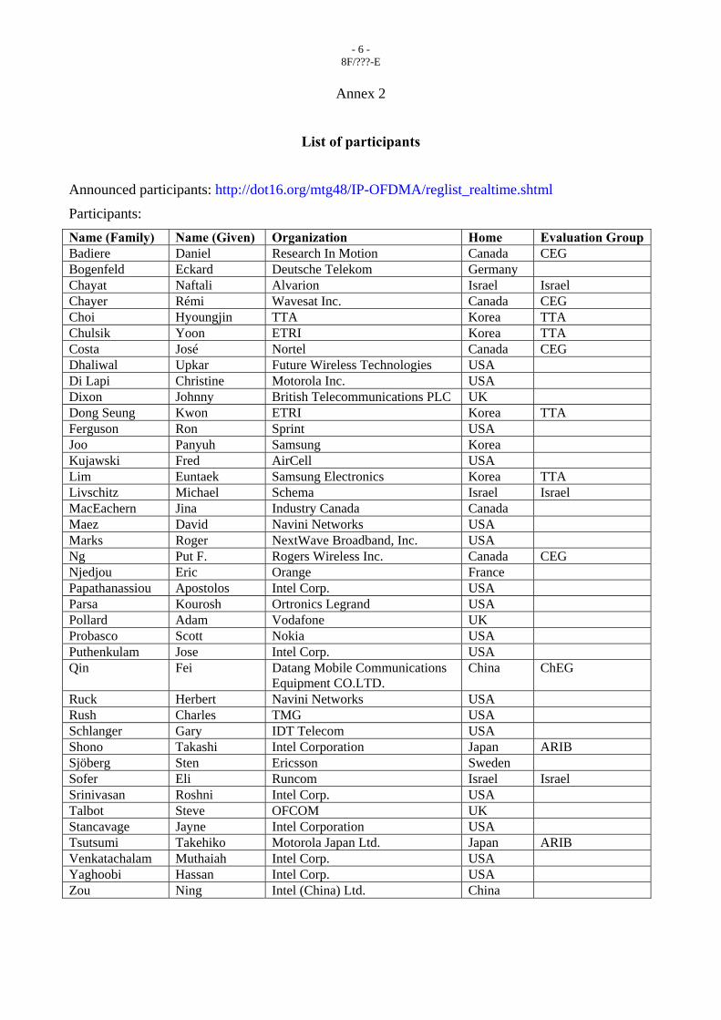
List of participants
Announced participants: http://dot16.org/mtg48/IP-OFDMA/reglist_realtime.shtml
Participants: Name (Family) Name (Given) Organization Home Evaluation Group Badiere Daniel Research In Motion Canada CEG Bogenfeld Eckard Deutsche Telekom Germany Chayat Naftali Alvarion Israel Israel Chayer Rémi Wavesat Inc. Canada CEG Choi Hyoungjin TTA Korea TTA Chulsik Yoon ETRI Korea TTA Costa José Nortel Canada CEG Dhaliwal Upkar Future Wireless Technologies USA Di Lapi Christine Motorola Inc. USA Dixon Johnny British Telecommunications PLC UK Dong Seung Kwon ETRI Korea TTA Ferguson Ron Sprint USA Joo Panyuh Samsung Korea Kujawski Fred AirCell USA Lim Euntaek Samsung Electronics Korea TTA Livschitz Michael Schema Israel Israel MacEachern Jina Industry Canada Canada Maez David Navini Networks USA Marks Roger NextWave Broadband, Inc. USA Ng Put F. Rogers Wireless Inc. Canada CEG Njedjou Eric Orange France Papathanassiou Apostolos Intel Corp. USA Parsa Kourosh Ortronics Legrand USA Pollard Adam Vodafone UK Probasco Scott Nokia USA Puthenkulam Jose Intel Corp. USA Qin Fei Datang Mobile Communications
Equipment CO.LTD. China ChEG
Ruck Herbert Navini Networks USA Rush Charles TMG USA Schlanger Gary IDT Telecom USA Shono Takashi Intel Corporation Japan ARIB Sjöberg Sten Ericsson Sweden Sofer Eli Runcom Israel Israel Srinivasan Roshni Intel Corp. USA Talbot Steve OFCOM UK Stancavage Jayne Intel Corporation USA Tsutsumi Takehiko Motorola Japan Ltd. Japan ARIB Venkatachalam Muthaiah Intel Corp. USA Yaghoobi Hassan Intel Corp. USA Zou Ning Intel (China) Ltd. China

- 7 - 8F/???-E
Annex 3
List of documents
The documents considered by the meeting are the following:
1. IEEE L802.16-07/003 (IEEE Meeting invitation sent to ITU-R).
2. IEEE C802.16-07/007r1 (Roger Marks, “Introduction to IEEE 802.16 Working Group and IEEE Std 802.16”).
3. IEEE C802.16-07/008 (Scott Probasco, “Introduction to IP-OFDMA and 8F/1065”).
4. IEEE C802.16-07/009 (Jayne Stancavage, “Review of 8F/1075: Benefits of IP-OFDMA”).
5. IEEE C802.16-07/010 (Hassan Yaghoobi, “Review of 8F/1079(Rev.1): Additional Technical Details Supporting IP-OFDMA as an IMT-2000 Terrestrial Radio Interface”).
6. ITU-R Doc. 8F/1065 (IEEE)
7. ITU-R Doc. 8F/1075 (WiMAX Forum)
8. ITU-R Doc. 8F/1079(Rev.1) (WiMAX Forum)

- 8 - 8F/???-E
Annex 4
Questions and answers for clarification on the self-evaluation
(Reference: Section 3 of Document 8F/1079(Rev.1))
Index Criteria and attributes Q
or q
Gn Related
attributes in Annex 1
Proponents Comments Coordination meeting questions and answers
A3.1 Spectrum efficiency :
The following entries are considered in the evaluation of spectrum efficiency
A3.1.1 For terrestrial environment
A3.1.1.1 Voice traffic capacity (E/MHz/cell) in a total available assigned non-contiguous bandwidth of 30 MHz (15 MHz forward/15 MHz reverse) for FDD mode or contiguous bandwidth of 30 MHz for TDD mode.
This metric must be used for a common generic continuous voice bearer with characteristics 8 kbit/s data rate and an average BER 1 � 10-3 as well as any other voice bearer included in the proposal which meets the quality requirements (assuming 50% voice activity detection (VAD) if it is used). For comparison purposes, all measures should assume the use of the deployment models in Annex 2, including a 1% call blocking. The descriptions should be consistent with the descriptions under criterion § 6.1.7 – Coverage/power efficiency. Any other assumptions and the background for the calculation should be provided, including details of any optional speech codecs being considered.
Q and
q
G1 A1.3.1.5.1 TDD mode Voice capacity using VoIP:
-90 Erlangs/MHz/cell for reuse 3, SIMO, 10 MHz PUSC Subchannelization
-80 Erlangs/MHz/cell for reuse 3, SIMO, 5 MHz PUSC Subchannelization
Assumptions:
-ITU vehicular path loss model
-Pedestrian B3 channel model
Q1 = Is a cell one sector or multiple sectors?
A1 =In the self-evaluation a cell is 3 sectors.
Q2 = What is the reason for 80 vs 90 Erlangs?
A2 = It is due to MAC overheads, being slightly less in the 10 MHz case.

- 9 - 8F/???-E
A3.1.1.2 Information capacity
(Mbit/s/MHz/cell) in a total available assigned non-contiguous bandwidth of 30 MHz (15 MHz forward/15 MHz reverse) for FDD mode or contiguous bandwidth of 30 MHz for TDD mode.
The information capacity is to be calculated for each test service or traffic mix for the appropriate test environments. This is the only measure that would be used in the case of multimedia, or for classes of services using multiple speech coding bit rates. Information capacity is the instantaneous aggregate user bit rate of all active users over all channels within the system on a per cell basis. If the user traffic (voice and/or data) is asymmetric and the system can take advantage of this characteristic to increase capacity, it should be described qualitatively for the purposes of evaluation.
Q and
q
G1 A1.3.1.5.2 For the packet data bearer (UDD) service:
Data capacity:
-DL SIMO 5MHz= 3.45 Mbit/s/MHz/cell
-DL SIMO 10MHz = 3.57 Mbit/s/MHz/cell
-UL SIMO 5MHz = 1.6 Mbit/s/MHz/cell
-DL MIMO 10MHz= 5.52 Mbit/s/MHz/cell
-UL SIMO 10MHz= 1.59 Mbit/s/MHz/cell
-UL MIMO 10MHz= 2.1 Mbit/s/MHz/cell
Assumptions:
- PUSC, ITU vehicular, 60% Pedestrian B 3, 30% Vehicular A 30, 10% Vehicular A 120,
-DL:UL=28:9 (payload only)
A3.1.2 For satellite environment
These values (§ A3.1.2.1 and A3.1.2.2) assume the use of the simulation conditions in Annex 2. The first definition is valuable for comparing systems with identical user channel rates. The second definition is valuable for comparing systems with different voice and data channel rates.
A3.1.2.1 Voice information capacity per required RF bandwidth (bit/s/Hz)
Q G1 A1.3.2.3.1 NA
A3.1.2.2 Voice plus data information capacity per required RF bandwidth (bit/s/Hz)
Q G1 A1.3.2.3.2 NA
A3.2 Technology complexity – Effect on cost of installation and operation
The considerations under criterion § 6.1.2 – Technology complexity apply only to the infrastructure, including BSs (the handportable performance is considered elsewhere).
- 10 - 8F/???-E
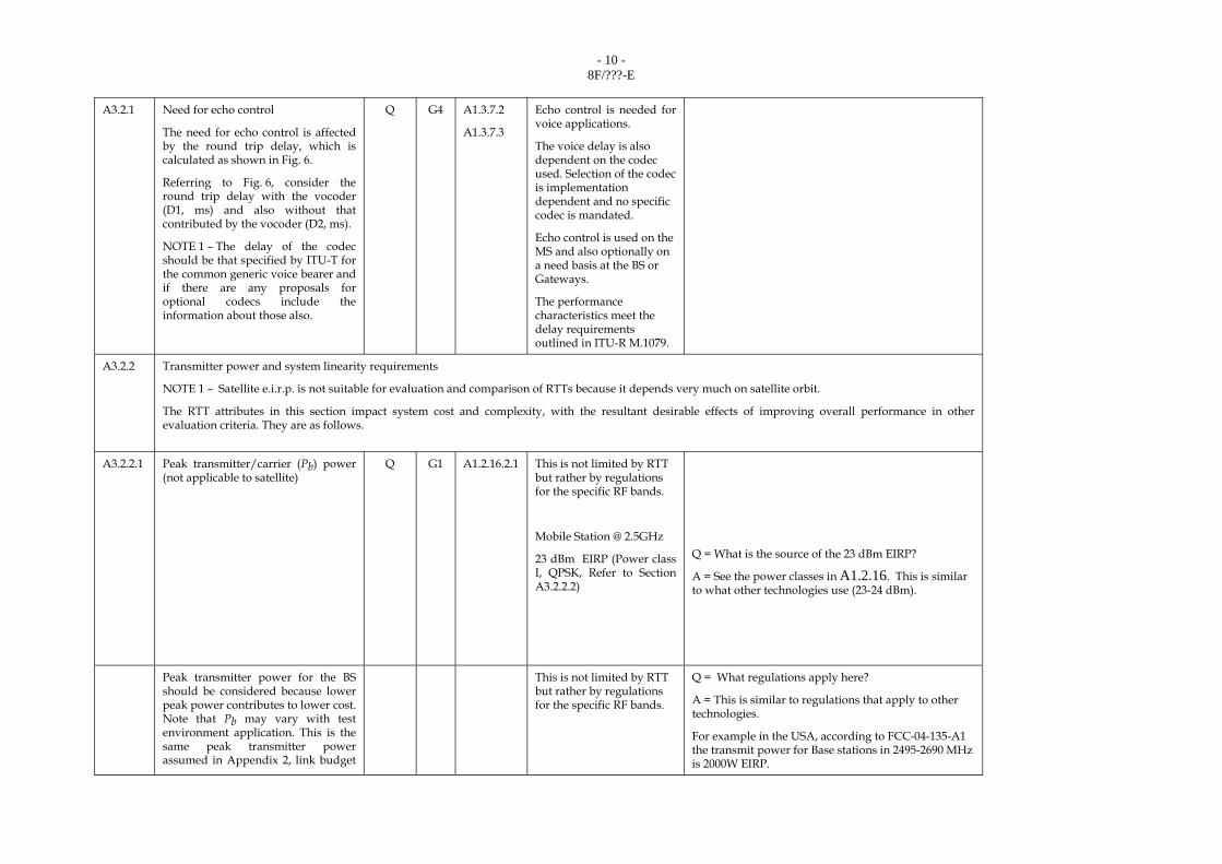
A3.2.1 Need for echo control
The need for echo control is affected by the round trip delay, which is calculated as shown in Fig. 6.
Referring to Fig. 6, consider the round trip delay with the vocoder (D1, ms) and also without that contributed by the vocoder (D2, ms).
NOTE 1 – The delay of the codec should be that specified by ITU-T for the common generic voice bearer and if there are any proposals for optional codecs include the information about those also.
Q G4 A1.3.7.2
A1.3.7.3
Echo control is needed for voice applications.
The voice delay is also dependent on the codec used. Selection of the codec is implementation dependent and no specific codec is mandated.
Echo control is used on the MS and also optionally on a need basis at the BS or Gateways.
The performance characteristics meet the delay requirements outlined in ITU-R M.1079.
A3.2.2 Transmitter power and system linearity requirements
NOTE 1 – Satellite e.i.r.p. is not suitable for evaluation and comparison of RTTs because it depends very much on satellite orbit.
The RTT attributes in this section impact system cost and complexity, with the resultant desirable effects of improving overall performance in other evaluation criteria. They are as follows.
A3.2.2.1 Peak transmitter/carrier (Pb) power (not applicable to satellite)
Q G1 A1.2.16.2.1 This is not limited by RTT but rather by regulations for the specific RF bands.
Mobile Station @ 2.5GHz
23 dBm EIRP (Power class I, QPSK, Refer to Section A3.2.2.2)
Q = What is the source of the 23 dBm EIRP?
A = See the power classes in A1.2.16. This is similar to what other technologies use (23-24 dBm).
Peak transmitter power for the BS should be considered because lower peak power contributes to lower cost. Note that Pb may vary with test environment application. This is the same peak transmitter power assumed in Appendix 2, link budget
This is not limited by RTT but rather by regulations for the specific RF bands.
Q = What regulations apply here?
A = This is similar to regulations that apply to other technologies.
For example in the USA, according to FCC-04-135-A1 the transmit power for Base stations in 2495-2690 MHz is 2000W EIRP.

- 11 - 8F/???-E
template (Table 23).
A3.2.2.2 Broadband power amplifier (PA) (not applicable to satellite) Is a broadband power amplifier used or required? If so, what are the peak and average transmitted power requirements into the antenna as measured in watts.
Q G1 A1.4.10 A1.2.16.2.1 A1.2.16.2.2 A1.5.5 A1.2.5
A broadband power amplifier is required. Tx Power is not limited by RTT but by regulations.
BS
- Tx dynamic range = 10 dB
- Spectral flatness as per conditions in A.1.4.10
- Peak Tx power on BS is limited only by regulations and not by the RTT.
MS
- Tx dynamic range = 45 dB
- Spectral flatness as per conditions in A.1.4.10
- 4 power classes are supported as shown below:
Peak Transmit power (dBm) for 16QAM
1. 18 <= Ptx,max < 21
2. 21 <= Ptx,max < 25
3. 25 <= Ptx,max < 30
4. 30 <= Ptx,max
Peak Transmit power (dBm) for QPSK
Q1 = Peak is given, what is the average power?
A1 = The average power varies and it is dependent on antenna configuration, services, duty cycles, how far is mobile to the base (i.e., implementation and operation dependent). It lies between the peak power and the minimum power, which is the peak power minus the dynamic range that is dictated by the implementation.
Q2 = Why are there no 64QAM numbers for the uplink?
A2 = 64QAM is optional, that’s why peak transmit power is not classified.

- 12 - 8F/???-E
1. 20 <= Ptx,max < 23
2. 23 <= Ptx,max < 27
3. 27 <= Ptx,max < 30
4. 30 <= Ptx,max
A3.2.2.3 Linear base transmitter and broadband amplifier requirements (not applicable to satellite)
A3.2.2.3.1
Adjacent channel splatter/emission and intermodulation affect system capacity and performance. Describe these requirements and the linearity and filtering of the base transmitter and broadband PA required to achieve them.
q G3 A1.4.2 A1.4.10
Base stations and terminals supporting this RTT will comply with local, regional, and international regulations for out of band and spurious emissions, wherever applicable.
A3.2.2.3.2
Also state the base transmitter and broadband PA (if one is used) peak to average transmitter output power, as a higher ratio requires greater linearity, heat dissipation and cost.
Q and
q
G2 A1.4.10 A1.2.16.2.1 A1.2.16.2.2
These are implementation dependent. The PAPR of the proposed RTT is around 12dB
PAPR = peak to average power ratio
A3.2.2.4 Receiver linearity requirements (not applicable to satellite)
Is BS receiver linearity required? If so, state the receiver dynamic range required and the impact of signal input variation exceeding this range, e.g., loss of sensitivity and blocking.
q G4 A1.4.11 A1.4.12
BS
Max input level on-channel reception tolerance = -45 dBm
Max input level on-channel damage tolerance = -10 dBm
MS
Max input level on-channel reception tolerance = -30 dBm
Max input level on-channel damage tolerance = 0 dBmBS/MS
BS and MS
Max input level sensitivity
Q = What are the linearity requirements and what is the dynamic range?
A = It is described in A3.6.7. Also, the dynamic range is specified in A3.6.8.
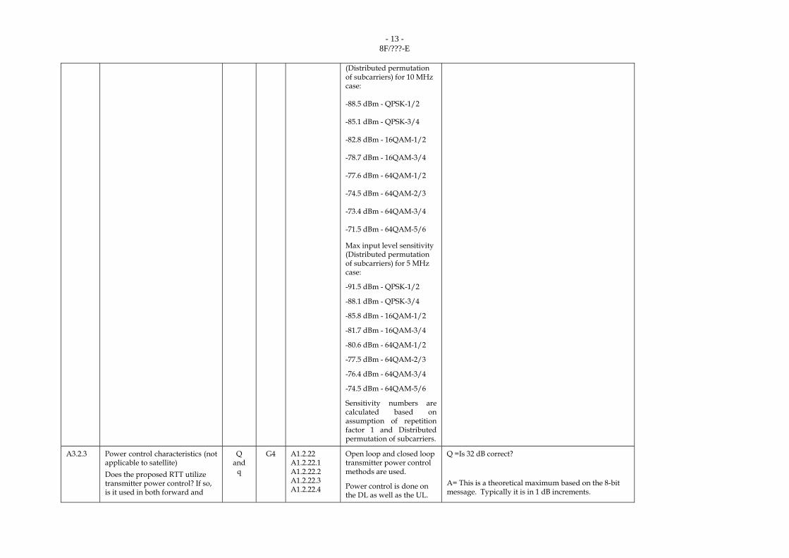
- 13 - 8F/???-E
(Distributed permutation of subcarriers) for 10 MHz case:
-88.5 dBm - QPSK-1/2
-85.1 dBm - QPSK-3/4
-82.8 dBm - 16QAM-1/2
-78.7 dBm - 16QAM-3/4
-77.6 dBm - 64QAM-1/2
-74.5 dBm - 64QAM-2/3
-73.4 dBm - 64QAM-3/4
-71.5 dBm - 64QAM-5/6
Max input level sensitivity (Distributed permutation of subcarriers) for 5 MHz case:
-91.5 dBm - QPSK-1/2
-88.1 dBm - QPSK-3/4
-85.8 dBm - 16QAM-1/2
-81.7 dBm - 16QAM-3/4
-80.6 dBm - 64QAM-1/2
-77.5 dBm - 64QAM-2/3
-76.4 dBm - 64QAM-3/4
-74.5 dBm - 64QAM-5/6
Sensitivity numbers are calculated based on assumption of repetition factor 1 and Distributed permutation of subcarriers.
A3.2.3 Power control characteristics (not applicable to satellite) Does the proposed RTT utilize transmitter power control? If so, is it used in both forward and
Q and
q
G4 A1.2.22 A1.2.22.1 A1.2.22.2 A1.2.22.3 A1.2.22.4
Open loop and closed loop transmitter power control methods are used.
Power control is done on the DL as well as the UL.
Q =Is 32 dB correct?
A= This is a theoretical maximum based on the 8-bit message. Typically it is in 1 dB increments.
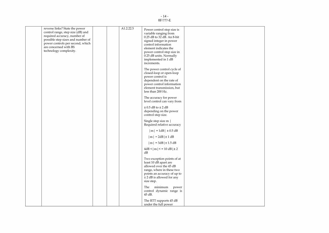
- 14 - 8F/???-E
reverse links? State the power control range, step size (dB) and required accuracy, number of possible step sizes and number of power controls per second, which are concerned with BS technology complexity.
A1.2.22.5 Power control step size is variable ranging from 0.25 dB to 32 dB. An 8-bit signed integer in power control information element indicates the power control step size in 0.25 dB units. Normally implemented in 1 dB increments.
The power control cycle of closed-loop or open-loop power control is dependent on the rate of power control information element transmission, but less than 200 Hz.
The accuracy for power level control can vary from
± 0.5 dB to ± 2 dB depending on the power control step size.
Single step size m | Required relative accuracy
|m| = 1dB| ± 0.5 dB
|m| = 2dB|± 1 dB
|m| = 3dB|± 1.5 dB
4dB <|m|< = 10 dB|± 2 dB
Two exception points of at least 10 dB apart are allowed over the 45 dB range, where in these two points an accuracy of up to ± 2 dB is allowed for any size step.
The minimum power control dynamic range is 45 dB.
The RTT supports 45 dB under the full power

- 15 - 8F/???-E
assumption
A3.2.4 Transmitter/receiver isolation requirement (not applicable to satellite)
If FDD is used, specify the noted requirement and how it is achieved.
q G3 A1.2.2 A1.2.2.2 A1.2.2.1
Not Applicable as it is TDD.
A3.2.5 Digital signal processing requirements
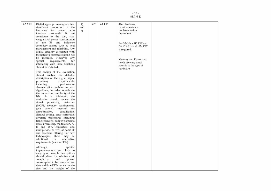
- 16 - 8F/???-E
A3.2.5.1 Digital signal processing can be a
significant proportion of the hardware for some radio interface proposals. It can contribute to the cost, size, weight and power consumption of the BS and influence secondary factors such as heat management and reliability. Any digital circuitry associated with the network interfaces should not be included. However any special requirements for interfacing with these functions should be included.
This section of the evaluation should analyse the detailed description of the digital signal processing requirements, including performance characteristics, architecture and algorithms, in order to estimate the impact on complexity of the BSs. At a minimum the evaluation should review the signal processing estimates (MOPS, memory requirements, gate counts) required for demodulation, equalization, channel coding, error correction, diversity processing (including Rake receivers), adaptive antenna array processing, modulation, A-D and D-A converters and multiplexing as well as some IF and baseband filtering. For new technologies, there may be additional or alternative requirements (such as FFTs).
Although specific implementations are likely to vary, good sample descriptions should allow the relative cost, complexity and power consumption to be compared for the candidate RTTs, as well as the size and the weight of the
Q and
q
G2 A1.4.13
The Hardware requirements are implementation dependent.
For 5 MHz a 512 FFT and for 10 MHz and 1024 FFT is required.
Memory and Processing needs are very much specific to the type of hardware.

- 17 - 8F/???-E
circuitry. The descriptions should allow the evaluators to verify the signal processing requirement metrics, such as MOPS, memory and gate count, provided by the RTT proponent.
A3.2.5.2 What is the channel coding/error handling for both the forward and reverse links? Provide details and ensure that implementation specifics are described and their impact considered in DSP requirements described in § A3.2.5.1.
q G4 A1.2.12 A1.4.13
An 8bit CRC is used for MAC PDU errors.
Forward Error Correction schemes Convolutional Coding and Convolutional Turbo Coding are supported
Modulation schemes:

- 18 - 8F/???-E
QPSK, 16 QAM and 64 QAM for downlink, QPSK and 16 QAM for uplink.
Coding rates: QPSK 1/2, QPSK 3/4, 16 QAM 1/2, 16 QAM 3/4, 64 QAM 1/2, 64 QAM 2/3, 64 QAM 3/4, 64 QAM 5/6.
Coding repetition rates: 1x, 2x, 4x and 6x.
A3.2.6 Antenna systems
The implementation of specialized antenna systems while potentially increasing the complexity and cost of the overall system can improve spectrum efficiency (e.g. smart antennas), quality (e.g. diversity), and reduce system deployment costs (e.g. remote antennas, leaky feeder antennas).
MS:
1 Tx Antenna
2 Rx Antennas
BS:
2 or more Tx Antennas
2 or more Rx Antennas
Both MIMO and Beamforming support are mandatory at the Mobile Stations. Base Stations may support either MIMO or Beamforming. In general, it is expected for Beamforming to be deployed in scenarios where increased coverage is required (urban and suburban scenarios), while MIMO is expected to be employed in scenarios requiring high system capacity (urban scenarios).
For MIMO operation: Adaptive switching between STC and SM is supported, see Section 1.3. 5 for a detailed description.

- 19 - 8F/???-E
Two transmit and two or more receive antennas are employed at the BS; one transmit and two receive antennas are supported at the MS. The typical antenna spacing at the BS and MS is 10 λ and 0.5 λ, respectively, where λ stands for the carrier wavelength. Regarding the type of equalizers for the SM MIMO mode, either minimum mean squared error (MMSE) or maximum-likelihhod (ML) based receivers will be implemented by MS vendors. Regarding the CSI, this is based either on physical or effective carrier-to-interference-and-noise ratio (CINR), while the communication of the MIMO mode is also enabled by the Mobile WiMAX system profiles. Please see also Section 1.3.5 for a detailed description.
For Beamforming operation: Typically, a BS transceiver is equipped with 4 transmit and receive antennas but larger number of antennas can be used. The antenna spacing depends on the used Beamforming algorithm and can range from 0.5 λ to 3 λ. Regarding the weight update operation, see also Section 1.3.5, this is based on channel sounding, which is the process of channel estimation during the uplink operation for updating the antenna weights to be used for the

- 20 - 8F/???-E
subsequent transmission to a particular user in the downlink. Note that due to the channel reciprocity enabled by the TDD operation, the weights are accurate for low MS speeds, e.g., up to 30 km/h, while a graceful degradation of the performance is expected for higher speeds. Certainly, the accuracy of the antenna weights is also highly dependent on the specific Beamforming algorithm used at the BS, which may lead to smaller performance degradation at higher MS speeds.
NOTE 1 – For the satellite component, diversity indicates the number of satellites involved; the other antenna attributes do not apply.
A3.2.6.1 Diversity : describe the diversity schemes applied (including micro and macro diversity schemes). Include in this description the degree of improvement expected, and the number of additional antennas and receivers required to implement the proposed diversity design beyond and omni-directional antenna.
Q G2 A1.2.23 A1.2.23.1 A1.2.23.2
When the MIMO option is deployed: In the downlink, both transmit diversity and receive diversity is supported through the use of STC (use of the Alamouti code which is a space-time block coding code for two transmit antennas, while two receive antennas are used at the MS for receive diversity). Note that when SM is used, although there is also inherent transmit and receive diversity due to the use of two antennas at both the BS and MS, the target is the increase of the peak rate by transmitting two data streams over one OFDMA symbol per

- 21 - 8F/???-E
subcarrier, see also Section 1.3.5 for a detailed description. In the uplink where CSM (collaborative spatial multiplexing) is supported, receive diversity is applied by the use of two or more receive antennas at the BS. Depending on the propagation environment (mainly characterized by the frequency and time diversity of the link-level channel model), the signal-to-noise ratio (SNR) gain of STC ranges from 4 dB to 7dB compared to a single antenna system; the SNR gain of SM ranges from 2 dB to 4 dB compared to a single antenna system, where there is double data throughput supported by SM compared to the single antenna system. Regarding the CSM mode, higher gains on the order of 1 dB to 2 dB are expected compared to the SM gains reported above.
When the Beamforming option is applied: In the downlink, transmit diversity is supported, while receive diversity is also applied when two receive antennas are used at the MS. In the uplink, receive diversity is supported by using multiple antenna reception at the BS. For a typical implementation of 4 receive and transmit antennas for Bemaforming, the SNR gains at both the uplink and the downlink
- 22 - 8F/???-E
are expected to range from 6 dB to 12 dB.
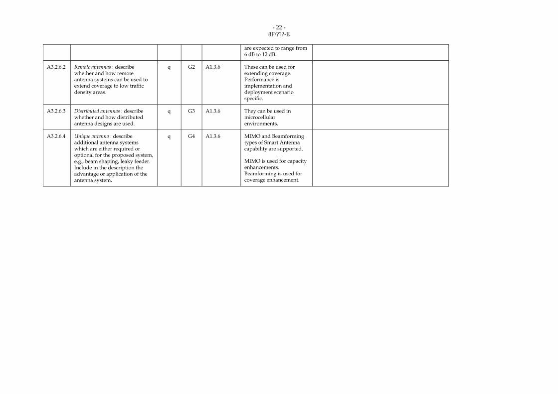
A3.2.6.2 Remote antennas : describe whether and how remote antenna systems can be used to extend coverage to low traffic density areas.
q G2 A1.3.6 These can be used for extending coverage. Performance is implementation and deployment scenario specific.
A3.2.6.3 Distributed antennas : describe whether and how distributed antenna designs are used.
q G3 A1.3.6 They can be used in microcellular environments.
A3.2.6.4 Unique antenna : describe additional antenna systems which are either required or optional for the proposed system, e.g., beam shaping, leaky feeder. Include in the description the advantage or application of the antenna system.
q G4 A1.3.6 MIMO and Beamforming types of Smart Antenna capability are supported.
MIMO is used for capacity enhancements. Beamforming is used for coverage enhancement.

- 23 - 8F/???-E
A3.2.7 BS frequency
synchronization/time alignment requirements
Does the proposed RTT require base transmitter and/or receiver station synchronization or base-to-base bit time alignment? If so, specify the long term (1 year) frequency stability requirements, and also the required bit-to-bit time alignment. Describe the means of achieving this.
Q and
q
G3 A1.4.1 A1.4.3
As it is a TDD system, BS synchronization is required. Methods used are implementation dependent. GPS based methods are typically used.
BS frequency tolerance ≤ ± 2ppm of carrier frequency
BS to BS frequency accuracy ≤ ± 1% of subcarrier spacing
MS to BS frequency synchronization tolerance ≤ 2% of the subcarrier spacing.
Time alignment between BS and MS is achieved using the Downlink Preambles and the Uplink ranging operation which corrects time offset errors. The OFDMA Cyclic Prefix marks the Symbol level time alignment.

- 24 - 8F/???-E
A3.2.8 The number of users per RF
carrier/frequency channel that the proposed RTT can support affects overall cost – especially as bearer traffic requirements increase or geographic traffic density varies widely with time.
Specify the maximum number of user channels that can be supported while still meeting ITU-T Recommendation G.726 performance requirements for voice traffic.
Q G1 A1.2.17 The maximum number of voice channels per 1 RF channel depends on the bit rate and sampling rate supported by the codecs defined in the G.726. For instance, in case of the bit rate of 16 kbit/s with 20 msec sampling rate, up to 256 users can be supported simultaneously by a 10 MHz RF channel, while meeting the delay requirements of VoIP. In the case of a 5 MHz channel up to 120 users can be supported.
The performance characteristics meet the delay and traffic requirements outlined in ITU-R M.1079.
Q = What is the rationale for 16 kbit/s?
A = This is an example only; it is similar to the bit rate used by other technologies.
A3.2.9 Base site implementation/installation requirements (not applicable to satellite)
BS size, mounting, antenna type and height can vary greatly as a function of cell size, RTT design and application environment. Discuss its positive or negative impact on system complexity and cost.
q G1 A1.4.17 No RTT specific requirements exist.
A3.2.10 Handover complexity
Consistent with handover quality objectives defined in criterion § 6.1.3, describe how user handover is implemented for both voice and data services and its overall impact on infrastructure cost and complexity.
Q
and q
G1 A1.2.24
A1.4.6.1
Simple Hard Handover and Optimized Hard Handover is supported. As the MS is only attached to one BS at a time significantly less complexity is expected.
As voice is supported as an application over the IP data bearer the handover is always treated as a data
Q = Is handover complexity less than what?
A = Less complexity than technologies requiring soft handover.
- 25 - 8F/???-E
connection.
Base stations and Mobile stations implement the ability to buffer data during handover as well the protocols necessary for handover.
See section 2.2.2.2 for handover performance analysis.
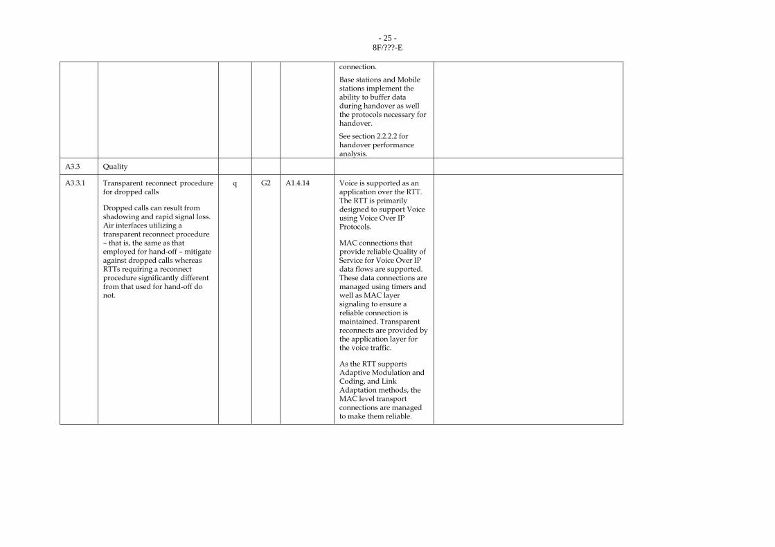
A3.3 Quality
A3.3.1 Transparent reconnect procedure for dropped calls
Dropped calls can result from shadowing and rapid signal loss. Air interfaces utilizing a transparent reconnect procedure – that is, the same as that employed for hand-off – mitigate against dropped calls whereas RTTs requiring a reconnect procedure significantly different from that used for hand-off do not.
q G2 A1.4.14 Voice is supported as an application over the RTT. The RTT is primarily designed to support Voice using Voice Over IP Protocols.
MAC connections that provide reliable Quality of Service for Voice Over IP data flows are supported. These data connections are managed using timers and well as MAC layer signaling to ensure a reliable connection is maintained. Transparent reconnects are provided by the application layer for the voice traffic.
As the RTT supports Adaptive Modulation and Coding, and Link Adaptation methods, the MAC level transport connections are managed to make them reliable.

- 26 - 8F/???-E
A3.3.2 Round trip delay, D1 (with
vocoder (ms)) and D2 (without vocoder (ms)) (See Fig. 6).
NOTE 1 – The delay of the codec should be that specified by ITU-T for the common generic voice bearer and if there are any proposals for optional codecs include the information about those also. (For the satellite component, the satellite propagation delay is not included.)
Q G2 A1.3.7.1 A1.3.7.2
Assuming G.729 with a vocoder delay of 20ms for a 20 Byte voice sample.
D1 = 20ms (vocoder) + 50ms (max one-way air interface delay) x 2 = 120ms
D2 = 50ms x 2 = 100ms
Q1 = Clarify 120 ms vs M.1225 requirements
Q2 = What does the “max” include?
A = D1 is the RTD including the vocoder delay, transmission delay, and the radio network delay; it does not include core network/backbone delay, which is assumed to be zero;
D1 = 2 x One way delay = 2 x ( 20 ms (vocoding) + 50ms { 5 ms (processing) + 10 ms (Tx+Rx) + 35 ms (radio network) } ) = 140 ms;
Note that the 35 ms is the delay through the anchor node which has a functionality similar to ASN or RNC.
A3.3.3 Handover/ALT quality
Intra switch/controller handover directly affects voice service quality.
Handover performance, minimum break duration, and average number of handovers are key issues.
Q G2 A1.2.24
A1.2.24.1 A1.2.24.2 A1.4.6.1
Handover signaling is designed to minimize loss of data.
Handover latency is <= 50ms if no network re-entry is required. This ensures minimum disruption to data transfer.
If NW re-entry is required the latency is <= 85ms.
Handover frequency is scenario specific.
A3.3.4 Handover quality for data
There should be a quantitative evaluation of the effect on data performance of handover.
Q G3 A1.2.24 A1.2.24.1 A1.2.24.2 A1.4.6.1
Handover for voice and data are treated the same way in this RTT.
A3.3.5 Maximum user bit rate for data (bit/s)
A higher user bit rate potentially provides higher data service quality (such as high quality video service) from the user’s point of view.
Q G1 A1.3.3 The maximum bit rates are well above 20160 kbit/s. (DL/UL ratio = 2:1, PUSC, 64QAM, 5/6 coding rate)
Q1 = Is this bit rate per user without considering the number of users
A1 = Yes
Q2 = Is the DL/UL ratio an RTT limitation?
A2= 2:1 is not an RTT limitation, but a typical value, used to arrive at the max bit rate.
A3.3.6 Channel aggregation to achieve higher user bit
There should also be a qualitative
q G4 A1.2.32 No channel aggregation is necessary as IP-OFDMA can operate over the entire

- 27 - 8F/???-E
evaluation of the method used to aggregate channels to provide higher bit rate services.
10 MHz channel.
However, flexible allocation of subchannels (in frequency domain) within an RF channel can be used to dynamically allocate bandwidth to individual users for various bit rate services (see also Section s 1.3.1 to 1.3.3) .
A3.3.7 Voice quality
Recommendation ITU-R M.1079 specifies that FPLMTS speech quality without errors should be equivalent to ITU-T Recommendation G.726 (32 kbit/s ADPCM) with desired performance at ITU-T Recommendation G.711 (64 kbit/s PCM).
NOTE 1 – Voice quality equivalent to ITU-T Recommendation G.726 error free with no more than a 0.5 degradation in MOS in the presence of 3% frame erasures might be a requirement.
Q and
q
G1 A1.2.19 A1.3.8
The vocoder is independent of the RTT. Any suitable vocoder can be used as voice is supported over using Voice over IP protocol.
Therefore the MOS values for the G.726 or any other vocoder used will apply.
Q = What is the MOS for VoIP?
A = Refer to ITU-T Recommendation G.114 (Figure 1)
A3.3.8 System overload performance (not applicable to satellite)
Evaluate the effect on system blocking and quality performance on both the primary and adjacent cells during an overload condition, at e.g. 125%, 150%, 175%, 200%. Also evaluate any other effects of an overload condition.
Q and
q
G3 A1.3.9.1 System overload causes graceful degradation as data transmission bandwidth can be traded off for lower quality connections.
As adaptive modulation and coding are supported the system adapts to the load conditions as per the policies implemented.
Q1 = What policies are these?
A1 = They are largely implementation dependent
Q2 = Will the QoS level also affect the degradation level during overload?
A2 = Yes; higher quality service will have less degradation.
Q3 = What is the reference point for the overload %
A3 = There is no specified reference point. It is an intra- and inter-operator operating point and it is

- 28 - 8F/???-E
operator dependent.
A3.4 Flexibility of radio technologies .
A3.4.1 Services aspects
A3.4.1.1 Variable user bit rate capabilities
Variable user bit rate applications can consist of the following:
– adaptive signal coding as a function of RF signal quality; – adaptive voice coder rate as a
function of traffic loading as long as ITU-T Recommendation G.726 performance is met;
– variable data rate as a function of user application; – variable voice/data channel
utilization as a function of traffic mix requirements.
Some important aspects which should be investigated are as follows:
– how is variable bit rate supported? – what are the limitations?
Supporting technical information should be provided such as
– the range of possible data rates, – the rate of changes (ms).
q and Q
G2 A1.2.18 A1.2.18.1
The user bit rates are variable according to the number of subchannels assigned and modulation and coding rate used.
The rates can be changed every 5ms which is every frame.
The DL-MAP and UL-MAP signal the changes every frame.
DOWNLINK
BW: 10 MHz
Modulation : QPSK, 16 QAM, 64 QAM
Coding rate : 1/2, 2/3, 3/4, 5/6
Data rates: 9.6 kbit/s to 23040 kbit/s
UPLINK
BW: 10 MHz
Modulation : QPSK, 16 QAM
Coding rate : 1/2, 3/4
Data rates: 9.6kbit/s to 6048 kbit/s
A3.4.1.2 Maximum tolerable Doppler shift, Fd (Hz) for which voice and data quality requirements are met (terrestrial only)
Supporting technical
q and Q
G3 A1.3.1.4 Fd ~500 Hz
Voice and Data are treated the same way from the Physical layer perspective.

- 29 - 8F/???-E
information: Fd
A3.4.1.3 Doppler compensation method (satellite component only)
What is the Doppler compensation method and residual Doppler shift after compensation?
Q and
q
G3 A1.3.2.2 NA
A3.4.1.4 How the maximum tolerable delay spread of the proposed technology impact the flexibility (e.g., ability to cope with very high mobile speed)?
q G3 A1.3.1.3 A1.2.14 A1.2.14.1 A1.2.14.2 A1.3.10
~20µs of delay spread can be tolerated without an equalizer.
A3.4.1.5 Maximum user information bit rate, Ru (kbit/s)
How flexibly services can be offered to customers ?
What is the limitation in number of users for each particular service? (e.g. no more than two simultaneous 2 Mbit/s users)
Q and
q
G2 A1.3.3 A1.3.1.5.2 A1.2.31 A1.2.32
Assuming 10 MHz PUSC:
- 23040 kbit/s for the Downlink (DL:UL=35:12)
- 6048 kbit/s for the Uplink for (DL:UL=26:21)
Services are very flexible as the Subchannels can be grouped to increase data rates.
A3.4.1.6 Multiple vocoder rate capability
– bit rate variability, – delay variability, – error protection variability.
Q and
q
G3 A1.2.19 A1.2.19.1 A1.2.7
Yes. Vocoders are however independent of the RTT and are implementation specific.
The data transports for voice can operate at varying levels of Packet error rate and using H-ARQ can significantly boost performance.
A3.4.1.7 Multimedia capabilities
The proponents should describe how multimedia services are handled.
The following items should be evaluated: – possible limitations (in data
Q and
q
G1 A1.2.21 A1.2.20 A1.3.1.5.2 A1.2.18 A1.2.24 A1.2.30 A1.2.30.1
The Data bearers have no constraints on the type of media they can carry. However typically they are mapped to the QoS of the media type being transmitted.
There are no limits on the

- 30 - 8F/???-E
rates, number of bearers),
– ability to allocate extra bearers during of the communication,
– constraints for handover.
number of bearers as long as bandwidth is available. Extra bearers can be allocated during communication. There are no handover constraints as long as coverage is available.
A3.4.2 Planning
A3.4.2.1 Spectrum related matters
A3.4.2.1.1
Flexibility in the use of the frequency band
The proponents should provide the necessary information related to this topic (e.g., allocation of sub-carriers with no constraints, handling of asymmetric services, usage of non-paired band).
q G1 A1.2.1 A1.2.2 A1.2.2.1 A1.2.3 A1.2.5.1
A 5 MHz or 10 MHz TDD carrier may be deployed with 1:3:3 frequency re-use or 1:3:1 reuse.
A3.4.2.1.2
Spectrum sharing capabilities
The proponent should indicate how global spectrum allocation can be shared between operators in the same region.
The following aspects may be detailed: – means for spectrum sharing
between operators in the same region,
– guardband between operators in case of fixed sharing.
q and Q
G4 A1.2.26 The proposed RTT utilizes OFDMA which has inherent interference protection capabilities due to allocation of a varying subset of available sub-carriers to different users. So spectrum sharing is carried out using multiple channel carriers. The guard bands are RF band specific.
A3.4.2.1.3
Minimum frequency band necessary to operate the system in good conditions
Supporting technical information: – impact of the frequency reuse pattern, – bandwidth necessary to carry
high peak data rate.
Q and
q
G1 A1.2.1 A1.4.15 A1.2.5
5 MHz or 10 MHz
1x3x3 PUSC or 1x3x1 PUSC may be used.
10 MHz gives the optimal data rate.
A3.4.2.2 Radio resource planning
A3.4.2.2. Allocation of radio resources q G2 A1.2.25 Subchannelization schemes

- 31 - 8F/???-E
1 The proponents and evaluators
should focus on the requirements and constraints imposed by the proposed technology. More particularly, the following aspects should be considered: – what are the methods used to
make the allocation and planning of radio resources flexible?
– what are the impacts on the network side (e.g. synchronization of BSs, signalling,)?
– other aspects.
Examples of functions or type of planning required which may be supported by the proposed technology: – DCA, – frequency hopping, – code planning, – time planning, – interleaved frequency planning.
NOTE 1 – The use of the second adjacent channel instead of the adjacent channel at a neighbouring cluster cell is called “interleaved frequency planning”.
In some cases, no particular functions are necessary (e.g. frequency reuse � 1).
A1.2.27 A1.4.15
and zones namely PUSC and AMC are supported to provide flexibility in utilizing the frequency and time resources.
Sectorized deployments are possible with flexible frequency re-use (1x3x3 or 1x3x1) using PUSC subchannelization schemes.
Slots of multiple subchannels and OFDM symbols are used to manage the resource allocation granularity
BSs need to be synchronized. This is typically done using GPS on the BS.
No frequency planning is required across cells.
A3.4.2.2.2
Adaptability to adapt to different and/or time varying conditions (e.g., propagation, traffic)
How the proposed technology cope with varying propagation and/or traffic conditions?
Examples of adaptive functions which may be supported by the proposed technology:
q G2 A1.3.10 A1.2.27 A1.2.22 A1.2.14
Subchannelization and slot structure capability provides the ability to schedule frequency/time resources to mitigate the effects of propagation losses and also for traffic load balancing.
Link adaptation schemes with CQI feedback
Q = Any other reasons?
A = The use of OFDMA makes this RTT particularly robust for multipath propagation.

- 32 - 8F/???-E
– DCA, – link adaptation, – fast power control, – adaptation to large delay
spreads.
Some adaptivity aspects may be inherent to the RTT.
capability allow operating the link more efficiently. H-ARQ also allows operations at high packet error rates resulting higher spectral efficiency as higher order coding and modulation rates can be used.
The OFDMA symbol structure is designed to reduce the effects of delay spreads up to 20µs.
A3.4.2.3 Mixed cell architecture (not applicable to satellite component)
A3.4.2.3.1
Frequency management between different layers What kind of planning is required to manage frequencies between the different layers? e.g. – fixed separation, – dynamic separation, – possibility to use the same
frequencies between different layers.
Possible supporting technical information: – guard band.
q and Q
G1 A1.2.28 A1.4.15
Hierarchical layered cells are possible.
The type of frequency planning is implementation/deployment scenario specific.
The same frequencies can be used across layers by proper segmentation of the PUSC Subchannels.
A3.4.2.3.2
User adaptation to the environment What are the constraints to the management of users between the different cell layers? e.g. – constraints for handover
between different layers, – adaptation to the cell layers
depending on services, mobile speed, mobile power.
q G2 A1.2.28 A1.3.10
The RTT does not impose constraints on the management of users between different cell layers in such a hierarchical deployment.
A3.4.2.4 Fixed-wireless access
A3.4.2.4.1
The proponents should indicate how well its technology is suited for operation in the fixed wireless
q G4 A1.1.3 A1.3.5 A1.4.17
The RTT is very much suited for fixed wireless access as well.

- 33 - 8F/???-E
access environment. Areas which would need evaluation include (not applicable to satellite component): – ability to deploy small BSs
easily, – use of repeaters, – use of large cells, – ability to support fixed and
mobile users within a cell, – network and signaling simplification.
A1.4.7 A1.4.7.1
Pico or Micro cells or Macro cells and repeaters are possible. Both fixed and mobile users can work in the same cell.
Network signaling for fixed devices are simpler compared to mobile devices.
A3.4.2.4.2
Possible use of adaptive antennas (how well suited is the technology) (not applicable to satellite component) Is RTT suited to introduce adaptive antennas? Explain the reason if it is.
q G4 A1.3.6 Yes the RTT supports adaptive antenna/Beamforming solutions.
A3.4.2.4.3
Existing system migration capability
q G1 A1.4.16 NA
A3.5 Implication on network interface
A3.5.1 Examine the synchronization requirements with respect to the network interfaces.
Best case : no special accommodation necessary to provide synchronization.
Worst case : special accommodation for synchronization is required, e.g. additional equipment at BS or special consideration for facilities.
q G4 A1.4.3 Synchronization of the BSs across the network is required and this is typically accomplished using GPS.
A3.5.2 Examine the RTTs ability to minimize the network infrastructure involvement in cell handover.
Best case : neither PSTN/ISDN nor mobile switch involvement in
q G3 A1.2.24 A1.4.6.1
Handover within the same ASN (Access Service Network) does not involve the CSN (Core Service Network).
In most handover

- 34 - 8F/???-E
handover.
Worst case : landline network involvement essential for handover.
scenarios with neighboring cells there is minimal involvement of the CSN. Only the BS and ASN GW may need to be involved in these scenarios.
A3.5.3 Landline feature transparency
A3.5.3.1 Examine the network modifications required for the RTT to pass the standard set of ISDN bearer services.
Best case : no modifications required.
Worst case: substantial modification required, such as interworking functions.
q G1 A1.4.7.1 ISDN is supported as an application running over the IP protocol and is not natively supported.
As voice is supported using Voice over IP protocols, the use of ISDN is only involved interworking functions between the IP networks and PSTN.
A3.5.3.2 Examine the extent of the PSTN/ISDN involvement in switching functionality.
Best case : all switching of calls is handled by the PSTN/ISDN.
Worst case : a separate mobile switch is required.
q G2 A1.4.6 A1.4.8
PSTN/ISDN is not used for switching within the IP network.
A3.5.3.3 Examine the depth and duration of fading that would result in a dropped call to the PSTN/ISDN network. The robustness of an RTTs ability to minimize dropped calls could be provided by techniques such as transparent reconnect.
Q and
q
G3 A1.2.24 A1.4.14
Voice is supported as an application over the RTT. The robustness of the link maintained is implementation dependent. The RTT supports HARQ and hence can operate in higher Packer Error Rates up to 10%.
Q = Should define time and dB for fading? (e.g., in a table)
A = This is implementation dependent and is similar to other technologies.
A3.5.3.4 Examine the quantity and type of network interfaces necessary for the RTT based on the deployment model used for spectrum and coverage efficiencies. The assessment
Q G2 A1.2.30 A1.2.30.1 A1.4.9
The RTT design is to minimize impacts on the network.
All the connections necessary for traffic,
- 35 - 8F/???-E
should include those connections necessary for traffic, signalling and control as well as any special requirements, such as soft handover or simulcast.
signaling and control terminate on the BS for PHY/MAC layer. The Radio Resource Management functions implemented over the IP protocol reside in the ASN. So most RTT configuration parameters are controlled on the BS which is interfaced using an IP connection to the ASN-GW .
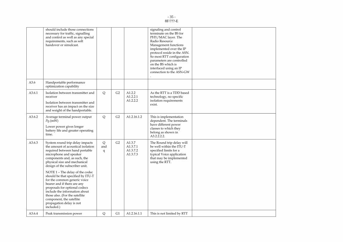
A3.6 Handportable performance optimization capability
A3.6.1 Isolation between transmitter and receiver
Isolation between transmitter and receiver has an impact on the size and weight of the handportable.
Q G2 A1.2.2 A1.2.2.1 A1.2.2.2
As the RTT is a TDD based technology, no specific isolation requirements exist.
A3.6.2 Average terminal power output P0 (mW)
Lower power gives longer battery life and greater operating time.
Q G2 A1.2.16.1.2 This is implementation dependent. The terminals have different power classes to which they belong as shown in A3.2.2.2.2.
A3.6.3 System round trip delay impacts the amount of acoustical isolation required between hand portable microphone and speaker components and, as such, the physical size and mechanical design of the subscriber unit.
NOTE 1 – The delay of the codec should be that specified by ITU-T for the common generic voice bearer and if there are any proposals for optional codecs include the information about those also. (For the satellite component, the satellite propagation delay is not included.)
Q and
q
G2 A1.3.7 A1.3.7.1 A1.3.7.2 A1.3.7.3
The Round trip delay will be well within the ITU-T specified limits for a typical Voice application that may be implemented using the RTT.
A3.6.4 Peak transmission power Q G1 A1.2.16.1.1 This is not limited by RTT

- 36 - 8F/???-E
but by regulations. The peak terminal power output P0 = 1000 mW (Power class 3). Also see A3.2.2.2.2 for more details.
A3.6.5 Power control characteristics
Does the proposed RTT utilize transmitter power control? If so, is it used in both forward and reverse links? State the power control range, step size (dB) and required accuracy, number of possible step sizes and number of power controls per second, which are concerned with mobile station technology complexity.
Yes the RTT does utilize transmitter power control for both Downlink and Uplink.
Q = Are the answers to all the questions available?
A = See A3.6.5.1, A3.6.5.2 for details.
The number of power controls per second is implementation dependent.
Maximum is less than 200 power controls per second. Typical values would be 5-20.
A3.6.5.1 Power control dynamic range
Larger power control dynamic range gives longer battery life and greater operating time.
Q G3 A1.2.22 A1.2.22.3 A1.2.22.4
The minimum power control dynamic range is 45 dB.
A3.6.5.2 Power control step size, accuracy and speed
Q G3 A1.2.22 A1.2.22.1 A1.2.22.2 A1.2.22.5
The accuracy for power level control can vary from
± 0.5 dB to ± 2 dB depending on the power control step size.
Single step size m | Required relative accuracy
|m| = 1dB| ± 0.5 dB
|m| = 2dB| ± 1 dB
|m| = 3dB| ± 1.5 dB
4dB< |m|< = 10dB| ± 2 dB
Two exception points of at least 10 dB apart are allowed over the 45 dB range, where in these two points an accuracy of up to +/- 2 dB is allowed for any size step.
Q = What is the difference between UL and DL?
A = A3.6 refers only to MS, therefore BS is not mentioned. See A3.2.3 for the BS related information.
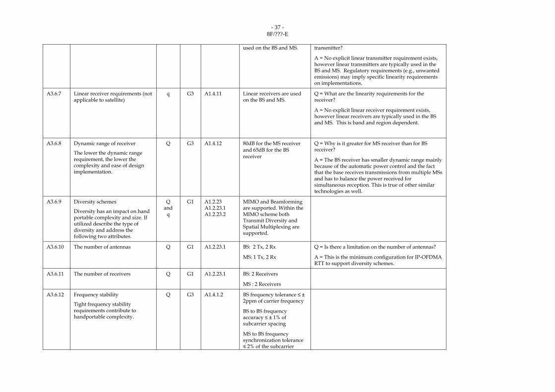
A3.6.6 Linear transmitter requirements q G3 A1.4.10 Linear transmitters are Q = What are the linearity requirements for the
- 37 - 8F/???-E
used on the BS and MS. transmitter?
A = No explicit linear transmitter requirement exists, however linear transmitters are typically used in the BS and MS. Regulatory requirements (e.g., unwanted emissions) may imply specific linearity requirements on implementations.
A3.6.7 Linear receiver requirements (not applicable to satellite)
q G3 A1.4.11 Linear receivers are used on the BS and MS.
Q = What are the linearity requirements for the receiver?
A = No explicit linear receiver requirement exists, however linear receivers are typically used in the BS and MS. This is band and region dependent.
A3.6.8 Dynamic range of receiver
The lower the dynamic range requirement, the lower the complexity and ease of design implementation.
Q G3 A1.4.12 80dB for the MS receiver and 65dB for the BS receiver
Q = Why is it greater for MS receiver than for BS receiver?
A = The BS receiver has smaller dynamic range mainly because of the automatic power control and the fact that the base receives transmissions from multiple MSs and has to balance the power received for simultaneous reception. This is true of other similar technologies as well.
A3.6.9 Diversity schemes
Diversity has an impact on hand portable complexity and size. If utilized describe the type of diversity and address the following two attributes.
Q and
q
G1 A1.2.23 A1.2.23.1 A1.2.23.2
MIMO and Beamforming are supported. Within the MIMO scheme both Transmit Diversity and Spatial Multiplexing are supported.
A3.6.10 The number of antennas Q G1 A1.2.23.1 BS: 2 Tx, 2 Rx
MS: 1 Tx, 2 Rx
Q = Is there a limitation on the number of antennas?
A = This is the minimum configuration for IP-OFDMA RTT to support diversity schemes.
A3.6.11 The number of receivers Q G1 A1.2.23.1 BS: 2 Receivers
MS : 2 Receivers
A3.6.12 Frequency stability
Tight frequency stability requirements contribute to handportable complexity.
Q G3 A1.4.1.2 BS frequency tolerance ≤ ± 2ppm of carrier frequency
BS to BS frequency accuracy ≤ ± 1% of subcarrier spacing
MS to BS frequency synchronization tolerance ≤ 2% of the subcarrier
- 38 - 8F/???-E
spacing
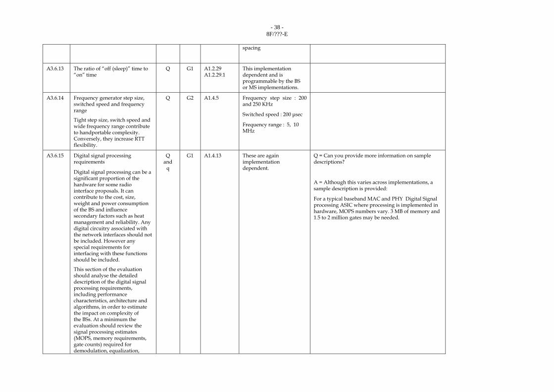
A3.6.13 The ratio of “off (sleep)” time to “on” time
Q G1 A1.2.29 A1.2.29.1
This implementation dependent and is programmable by the BS or MS implementations.
A3.6.14 Frequency generator step size, switched speed and frequency range
Tight step size, switch speed and wide frequency range contribute to handportable complexity. Conversely, they increase RTT flexibility.
Q G2 A1.4.5 Frequency step size : 200 and 250 KHz
Switched speed : 200 μsec
Frequency range : 5, 10 MHz
A3.6.15 Digital signal processing requirements
Digital signal processing can be a significant proportion of the hardware for some radio interface proposals. It can contribute to the cost, size, weight and power consumption of the BS and influence secondary factors such as heat management and reliability. Any digital circuitry associated with the network interfaces should not be included. However any special requirements for interfacing with these functions should be included.
This section of the evaluation should analyse the detailed description of the digital signal processing requirements, including performance characteristics, architecture and algorithms, in order to estimate the impact on complexity of the BSs. At a minimum the evaluation should review the signal processing estimates (MOPS, memory requirements, gate counts) required for demodulation, equalization,
Q and
q
G1 A1.4.13 These are again implementation dependent.
Q = Can you provide more information on sample descriptions?
A = Although this varies across implementations, a sample description is provided:
For a typical baseband MAC and PHY Digital Signal processing ASIC where processing is implemented in hardware, MOPS numbers vary. 3 MB of memory and 1.5 to 2 million gates may be needed.

- 39 - 8F/???-E
channel coding, error correction, diversity processing (including Rake receivers), adaptive antenna array processing, modulation, A-D and D-A converters and multiplexing as well as some IF and baseband filtering. For new technologies, there may be additional or alternative requirements (such as FFTs).
Although specific implementations are likely to vary, good sample descriptions should allow the relative cost, complexity and power consumption to be compared for the candidate RTTs, as well as the size and the weight of the circuitry. The descriptions should allow the evaluators to verify the signal processing requirement metrics, such as MOPS, memory and gate count, provided by the RTT proponent.
A3.7.1.1 Base site coverage efficiency
The number of base sites required to provide coverage at system start-up and ongoing traffic growth significantly impacts cost. From § 1.3.2 of Annex 2, determine the coverage efficiency, C (km2/base sites), for the lowest traffic loadings. Proponent has to indicate the background of the calculation and also to indicate the maximum coverage range.
Q G1 A1.3.1.7 A1.3.1.7.1 A1.3.1.7.2 A1.3.4
80-95% at system startup
95-100% in a mature system
See section 2.2.4.2 for more details.
Q1 = Where is the computation of C (coverage efficiency)?
A1 = See page 63 of Document 8F/1079(Rev.1) for the computation of C (Section 2.3.4.2).
Q2: What is the bit rate being considered in the computation of C?
A2 = It is taken from the link budget and applies to all traffic types in the link budget analysis.
A3.7.1.2 Method to increase the coverage efficiency
Proponent describes the technique adopted to increase the coverage efficiency and drawbacks.
Remote antenna systems can be
q G1 A1.3.5 A1.3.6
MIMO and Beamforming can be used to increase coverage efficiency.
Remote or Distributed antenna systems can also be used.
Q = Does it use repeaters?
A = The technology does not preclude them.
- 40 - 8F/???-E
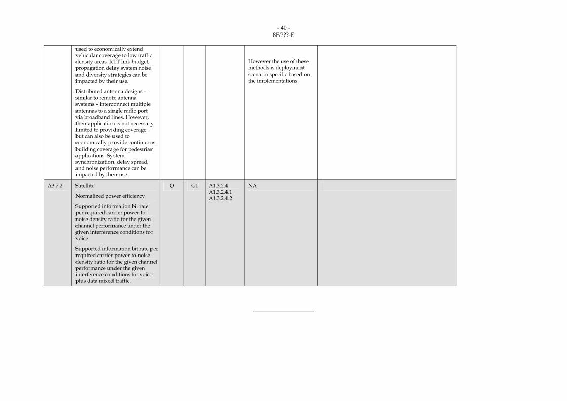
used to economically extend vehicular coverage to low traffic density areas. RTT link budget, propagation delay system noise and diversity strategies can be impacted by their use.
Distributed antenna designs – similar to remote antenna systems – interconnect multiple antennas to a single radio port via broadband lines. However, their application is not necessary limited to providing coverage, but can also be used to economically provide continuous building coverage for pedestrian applications. System synchronization, delay spread, and noise performance can be impacted by their use.
However the use of these methods is deployment scenario specific based on the implementations.
A3.7.2 Satellite
Normalized power efficiency
Supported information bit rate per required carrier power-to-noise density ratio for the given channel performance under the given interference conditions for voice
Supported information bit rate per required carrier power-to-noise density ratio for the given channel performance under the given interference conditions for voice plus data mixed traffic.
Q G1 A1.3.2.4 A1.3.2.4.1 A1.3.2.4.2
NA
_______________