instant dehazing of images using...
TRANSCRIPT
Proc. Computer Vision & Pattern Recognition Vol. 1, pp. 325-332 (2001). 1
Instant Dehazing of Images Using Polarization
Yoav Y. Schechner, Srinivasa G. Narasimhan and Shree K. NayarDepartment of Computer Science, Columbia University, New York, NY 10027
{yoav,srinivas,nayar }@cs.columbia.edu
AbstractWe present an approach to easily remove the effects of
haze from images. It is based on the fact that usuallyairlight scattered by atmospheric particles is partially po-larized. Polarization filtering alone cannot remove the hazeeffects, except in restricted situations. Our method, how-ever, works under a wide range of atmospheric and viewingconditions. We analyze the image formation process, tak-ing into account polarization effects of atmospheric scat-tering. We then invert the process to enable the removalof haze from images. The method can be used with as fewas two images taken through a polarizer at different ori-entations. This method works instantly, without relying onchanges of weather conditions. We present experimentalresults of complete dehazing in far from ideal conditionsfor polarization filtering. We obtain a great improvement ofscene contrast and correction of color. As a by product, themethod also yields a range (depth) map of the scene, andinformation about properties of the atmospheric particles.
1 Introduction
Recently there has been a growing interest in the analysisof images of scenes affected by weather phenomena. Themain objective has been to enhance [6, 10, 15, 24] imagestaken in poor visibility, and even restore the clear-day vis-ibility of the scene [11, 12, 14]. It has also been observedthat degradation of images by atmospheric scattering canactually be exploited to obtain information about the scene,particularly its range map [4, 12, 14]. Some image enhance-ment methods proposed in the past require prior informationabout the scene (e.g., distances [15, 24]). Other methods arebased on specialized radiation sources and detection hard-ware [16, 23].
Computer vision methods have restored clear-day vis-ibility of scenes using neither special radiation sourcesnor external knowledge about the scene structure oraerosols [11, 14]. These methods rely only on the acquiredimages, but require weather conditions to change betweenimage acquisitions. This can take too long to make dehaz-ing practical. They also require that the scattering propertieswill not vary with wavelength. This paper describes an ap-proach that does not need the weather conditions to change,and can thus be applied instantly. Moreover, in this ap-
proach the scattering properties may vary with wavelength.Our approach is based on analyzing images taken
through a polarizer. Polarization filtering has long beenused in photography through haze [20]. Relying only onoptical filtering is, however, restrictive: it is sufficient onlyon clear days, with weak light scattering (mainly due to airmolecules), when the sun is≈ 90o to the viewing direc-tion [9, 20]. In these situations photographers set the po-larization filter at an orientation that best improves imagecontrast. In general, however, polarization filtering alonecannotremove the haze from images. Here, we obtain muchmore than optics alone can yield by analyzing the polariza-tion filtered images.
The analysis of polarization filtered images has proved tobe useful for computer vision. For example, it was used toanalyze specularities [13, 17, 25], separate transparent andsemi-reflected scenes [7, 18, 19], classify materials [26],and segmenting scenes [1]. We note that advances in po-larimetric cameras [1, 21, 25, 26] enable acquisition of po-larization information in real time.
In this paper we model the image formation process, tak-ing into account polarization effects of atmospheric scat-tering in haze. We then use this model to recover the de-hazed scene, and also obtain information about scene struc-ture and atmospheric properties. Our approachdoes notre-quire modeling of the scattering particles’ size or their pre-cise scattering mechanisms. The principle is very simple:the image is composed of two unknown components - thescene radiance in the absence of haze, and airlight (the am-bient light scattered towards the viewer). To recover thesetwo unknowns we need two independent images. We easilyobtain these images because usually airlight is partially po-larized. The method only requires that the airlight inducessomedetectable partial polarization. We demonstrate re-moval of haze effects from a real scene in a situation wherepure optical filtering (without applying our algorithm) doesnotsuffice at all.
2 Theoretical Background2.1 Airlight Polarization
One of the causes for image degradation associated withatmospheric scattering isairlight. In this process, lightcoming from the illumination sources (e.g., the sun) is scat-tered towards the viewer [14]. Consider Fig. 1. The airlight
A
R
T
filterpolarizing
object
airlight
θ
scattering
illumination
direct
α
transmission
distance z
radiance
camera
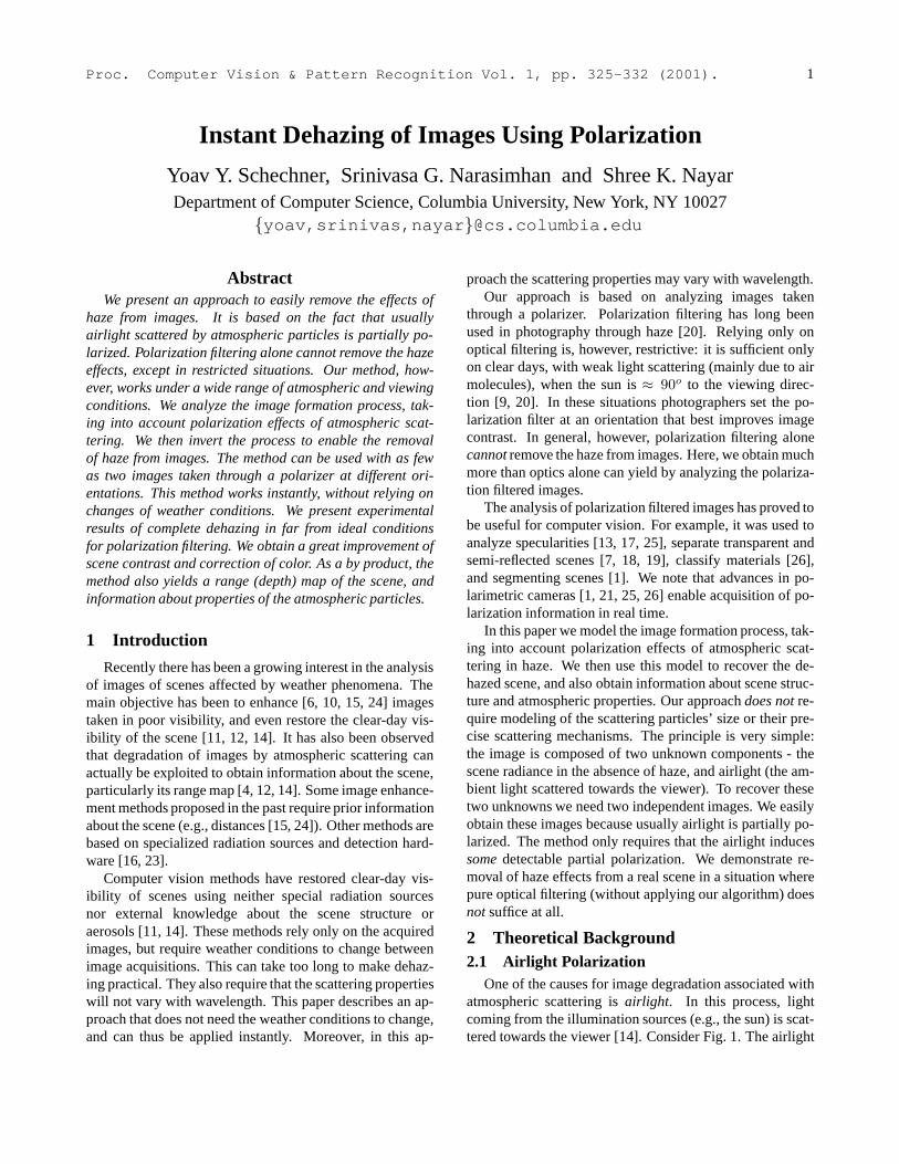
Figure 1. [Dashed rays] Light coming from the illuminant (e.g., sun) and scattered by atmospheric particles towards the camera is theairlight A. The airlight increases with the distancez of the object. [Solid ray] The light emanating from the objectR is attenuated byscattering along the line of sight, leading to the direct transmissionT . The direct transmission decreases withz. The scene is imagedthrough a polarizing filter at angleα. The polarization component parallel to the plane of incidence is best transmitted through thefilter atα = θ‖.
increases with the distancez from the object:
A = A∞(1 − e−βz
), (1)
whereβ is the scattering coefficient [11]. HereA∞ is theairlight corresponding to an object at an infinite distance,which we may take as the horizon.
Assume for a moment that the illumination of any scat-tering particle comes from one direction (one illuminationsource). The light ray from the source to a scatterer and theline of sight from the camera to the scatterer define aplaneof incidence. We divide the airlight intensity into two com-ponents1, that areparallel andperpendicularto this plane,A‖ and A⊥, respectively. The scattered light is partiallylinearly polarized perpendicular to this plane [8, 9]. Theairlight degree of polarization is
P ≡ A⊥ − A‖
A, (2)
whereA = A⊥ + A‖ (3)
is the total airlight intensity given in Eq. (1). The degreeof polarization greatly varies as a function of the size of thescattering particles, their density and the viewing direction.We now explain the effectiveness of polarization in varioushaze and illumination conditions.
2.1.1 The Trivial Case
The strongest polarization effect is observed when the scat-tering is caused by independent air molecules and verysmall dust particles (Rayleigh scattering) [3, 9, 20, 26].
1In terms of the electric field vector associated with the airlight radi-ation: these are the expectation values of the squared projections of thisvector, parallel and perpendicular to the plane of incidence.
Only when the light source is normal to the viewing direc-tion, the airlight is totally polarized (P = 1) perpendicu-lar to the plane of incidence. Thus, it can be eliminatedif the image is captured through a polarizing filter orientedparallel to this plane. Dehazing in this case is thus trivial,because it is achieved by optical filtering alone. Note thatthis situation is very restricted. In contrast, our method isapplicable to more general situations.
2.1.2 The General Case
In general, the airlight will not be completely polarized.Thus, the polarizing filter, on its own, cannot remove theairlight. For example, in Rayleigh scatteringP decreases asthe direction of illumination deviates from90o (relative tothe viewing direction). The degree of polarizationP is alsodecreased bydepolarization. This is caused by multiplescatterings: an illuminant of a scattering particle may be an-other particle. Thus, light may undergo multiple scatteringsin the atmosphere, in random directions, before hitting theparticle that ultimately scatters part of this light towards theviewer. Each direction of scattering creates a different planeof incidence. Because the camera senses the sum of thesescatterings, the overall degree of polarization is reduced [2].Multiple scatterings [3, 8, 9, 20], are more probable whenthe particle size is large or when the density of scatterers ishigh (poorer visibility). To make matters more complicated,the depolarization depends on the wavelength [9, 20].
Fortunately, our algorithmdoes notrequire explicit mod-eling of the precise mechanisms of scattering. The methodis based on the fact that even a partial polarization of theairlight can be exploited in post-processing to remove scat-tering effects. However, this degree of polarization needsto be significant enough to be detected. There are some
2
weather conditions under which the algorithm will not beeffective, as discussed in Sec. 8.
2.2 Direct Transmission PolarizationIn addition to the presence of airlight, scattering de-
grades images by attenuating the light emanating fromscene objects. Let the scene radiance beR in the absence ofhaze (scattering) between the scene and the viewer. Whenhaze is present, as a ray of light progresses towards theviewer (Fig. 1), part of its energy is scattered to other di-rections. Thus, the light energy that reaches the viewer is anattenuated fraction ofR, called thedirect transmission[14].As a function of the distancez and scattering coefficientβ,the direct transmission is
T = Re−βz . (4)
The scattering of the directly transmitted light does notchange the polarization state [3, 8] of the incident light2,although the overall intensity is attenuated. Therefore, thedegree of polarization and the polarization direction of thetransmitted light do not change along the line of sight.
The assumption we make in this paper is that light em-anating from scene objects has insignificant polarization.It follows that the polarization of the direct transmissionis also insignificant. This assumption is invalid for spec-ular surfaces. Nevertheless, the polarization associatedwith specular objects becomes negligible when they are farenough. The reason is that the direct transmission decreases(Eq. 4) while airlight increases (Eq. 1) with distance. Thus,the polarization of the airlight dominates the measured light.Hence, the model becomes more accurate where it is neededmost - for distant objects that are most affected by haze.
Note that airlight is just the aggregation of light scat-tered by particles at various distances along the line of sight.Since the degree of polarization of this light does not changealong the line of sight,P (Eq. 2) does not depend on the dis-tance.
3 Image formationThe overall intensity we measure is the sum of the
airlight and the direct transmission. Without mounting apolarizer on the camera, the intensity is
Itotal = T + A . (5)
When a polarizer is mounted, the intensity changes as afunction of the polarizer orientation angleα. Fig. 2 de-scribes the intensity at a single pixel. The intensity is acosine function ofα (See details in Appendix A.2). On av-erage, the measured intensity isItotal/2.
One of our goals is to decouple the airlight from the di-rect transmission. Since we assume that direct transmission
2In some kinds of high altitude clouds, anisotropic particles may havea macroscopic preferred directionality [9]. There, this statement may nothold, and a different analysis may be needed.
T/2
T/2"best state"
I = + A= =A
0
+
T/2I = + A"worst state"
I
=A2
PA
I
2A =
Airlight
Atotal/2
A − ==
Direct transmission
θα
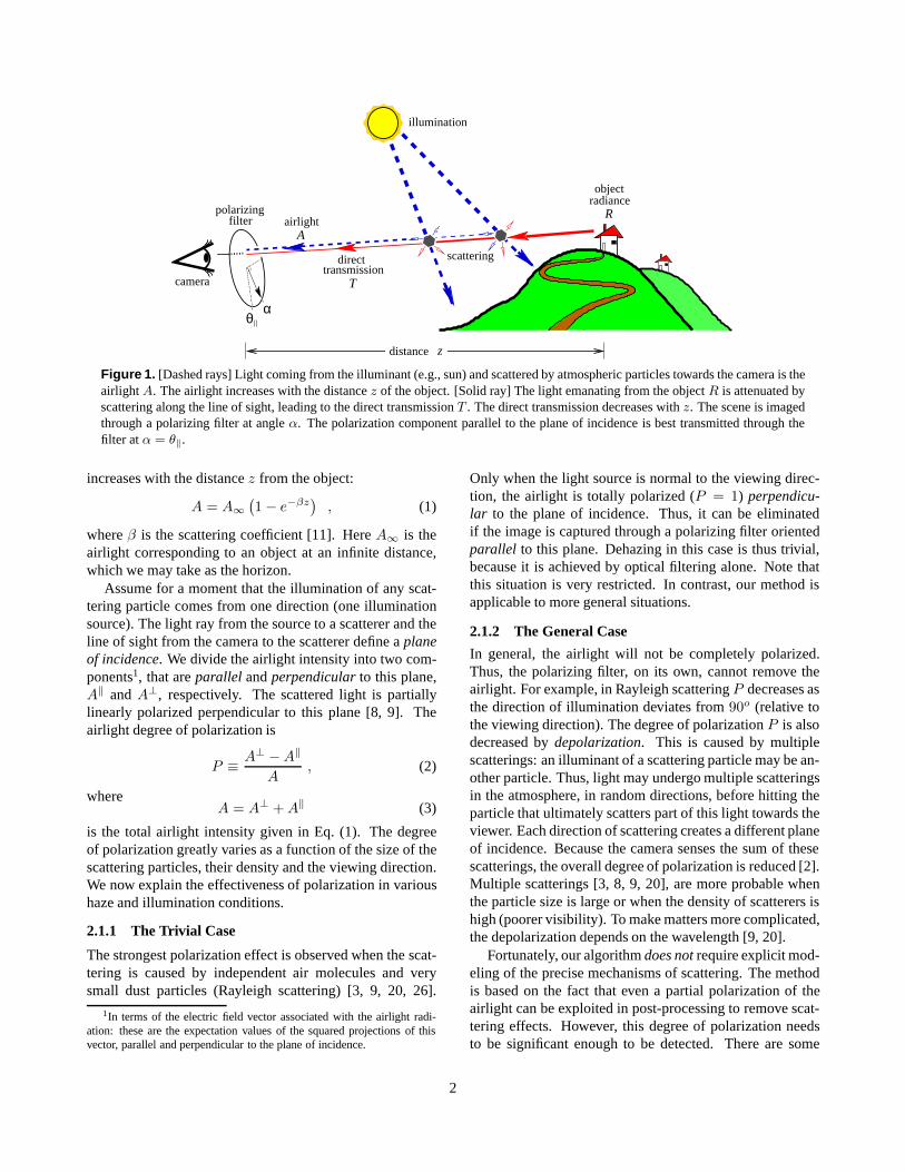
Figure 2. At each pixel, the minimum measured intensity asa function ofα is I‖. The maximum isI⊥. The differencebetween these measurements is due to the difference betweenthe airlight componentsA‖, A⊥. It is related to the unknownairlight intensityA by the parameterP , which is the airlightdegree of polarization. Without a polarizer the intensity isItotal. This intensity is comprised of the airlight intensityand the unknown direct transmission.
is not polarized, its energy is evenly distributed between thepolarization components. The variations due to the polar-izer rotation are assumed to be mainly due to the airlight.As seen in Fig. 2, when the polarizing filter is oriented par-allel to the plane of incidence (α = θ‖), we measure
I‖ = T/2 + A‖ , (6)
where (from Eqs. 2,3)
A‖ = A(1 − P )/2 . (7)
This is the “best state” of the polarizer, because here themeasured intensity is the closest to the direct transmission(except for a factor of 1/2). Still, there is a difference be-tweenI‖ andT/2, because the airlight is not completelypolarized (A‖ 6= 0).
In the next section, we recoverT by comparing two im-ages taken with different orientations of the polarizer. Forinstance, one image can beI‖, while the other,
I⊥ = T/2 + A⊥ (8)
is acquired when the filter is oriented perpendicular toθ‖.From Eqs. (2,3)
A⊥ = A(1 + P )/2 . (9)
From Eqs. (3,6,8),
Itotal = I‖ + I⊥ . (10)
Note thatI⊥ is the “worst state” of the polarizer, becausethe airlight is enhanced relative to the direct transmission.In order to dehaze the image we first have to remove theairlight. The key for that is the estimation ofP . As shown
3
I
IWorst polarization state
Best polarization state
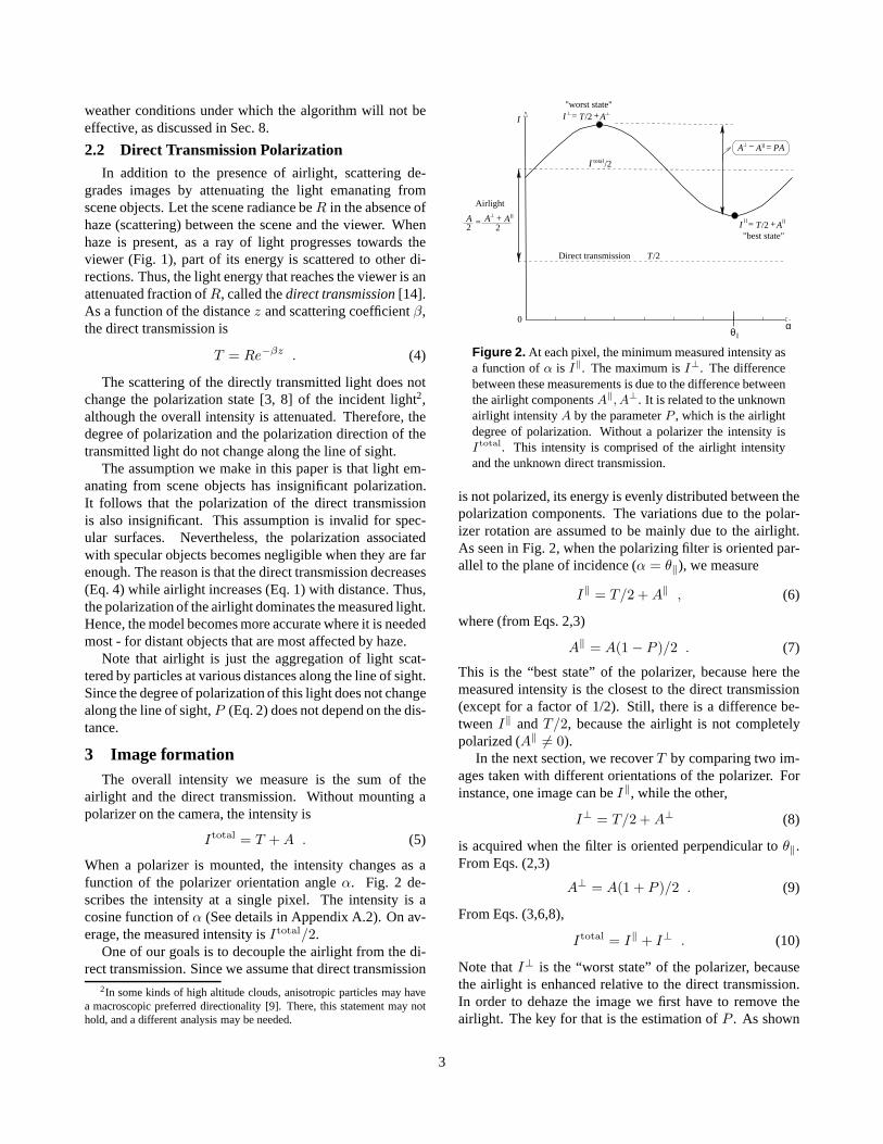
Figure 3. Images of the perpendicular and parallel polariza-tion components. The parallel component has the best im-age contrast that optics alone can give, but in this case it isonly slightly better than the contrast in the image of the worstpolarization state. The raw images were acquired instantly,without waiting for changes in the visibility.
in Fig. 2,P relates the unknown airlightA to the differencebetween the intensity measurements,I⊥ andI‖.
We took images of a distant scene at different orienta-tions of a polarizer. Fig. 3 shows the perpendicular and theparallel polarization components of the scene. The acqui-sition of the raw images wasnot conducted in the trivialsituation described in Sec. 2.1.1: the haze was rather dense(visibility of a few kilometers), indicating the abundance ofdepolarizing multiple scatterings. For this reason, the paral-lel component has only a slight improvement of image con-trast relative to the contrast in the perpendicular component.We note that due to the partial polarization of the airlight,I‖ was darker thanI⊥. For clarity of display, the intensityof each of the photos shown in Fig. 3 is contrast-stretched,while the hue and saturation are as in the raw images. Moredetails about obtaining these components are given in Ap-pendix A.2.
4 Dehazing ImagesFor each image pixel, we have three unknowns: the ob-
ject radiance (without haze)R, the airlightA and the scaleddepthβz. These determine the intensity at each image pixel.The airlight is related toβz by Eq. (1). Thus, the number ofunknowns per pixel is reduced to two. These unknowns can
be estimated fromtwo images taken at almostanygeneralunknown (but non-degenerate) orientations of the polariz-ing filter. This is proved in Appendix A.1. However, themost stable results are obtained if the algorithm is based onI‖ andI⊥. Therefore, we focus on this case.
Let the raw images correspond to the estimated polariza-tion components,I‖ andI⊥. Suppose we have an estimateof A∞ andP . One way to estimate these global parametersis described in Sec. 7. From Eqs. (6-9), it can be seen thatwe can estimate the airlight of any point as
A =I⊥ − I‖
P, (11)
and the unpolarized image (Eq. 10) as
Itotal = I‖ + I⊥ . (12)
Using Eq. (5), the estimated direct transmission is therefore
T = Itotal − A . (13)
In this image the additive effect of the airlight is removed.Recall that beside the addition of airlight, the haze atten-
uates the light coming from the object. The attenuation isestimated from Eqs. (1,11) as
e−βz = 1 − A
A∞. (14)
Thus, we can compensate for the attenuation of the trans-mitted light. From Eqs. (4,13,14) we obtain an estimate forthe scene radiance that would have been measured in theabsence of atmospheric scattering
R =Itotal − A
e−βz=
Itotal − A
1 − A/A∞. (15)
R is hence the dehazed image.We note thatA∞, P and β are functions of the light
wavelengthλ. For instance [3, 8], in Rayleigh scatteringβ ∼ 1/λ4. For this reason the airlight in moderate hazeis typically bluish. In order to account for the wavelengthdependence, it is best to analyze the images with high spec-tral resolution. Since we only have RGB channels in ourcamera, we performed the analysis for each channel inde-pendently.
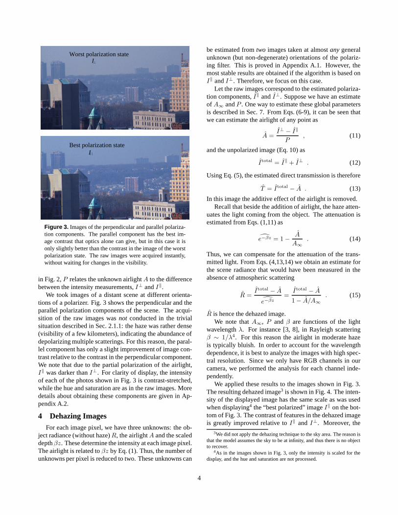
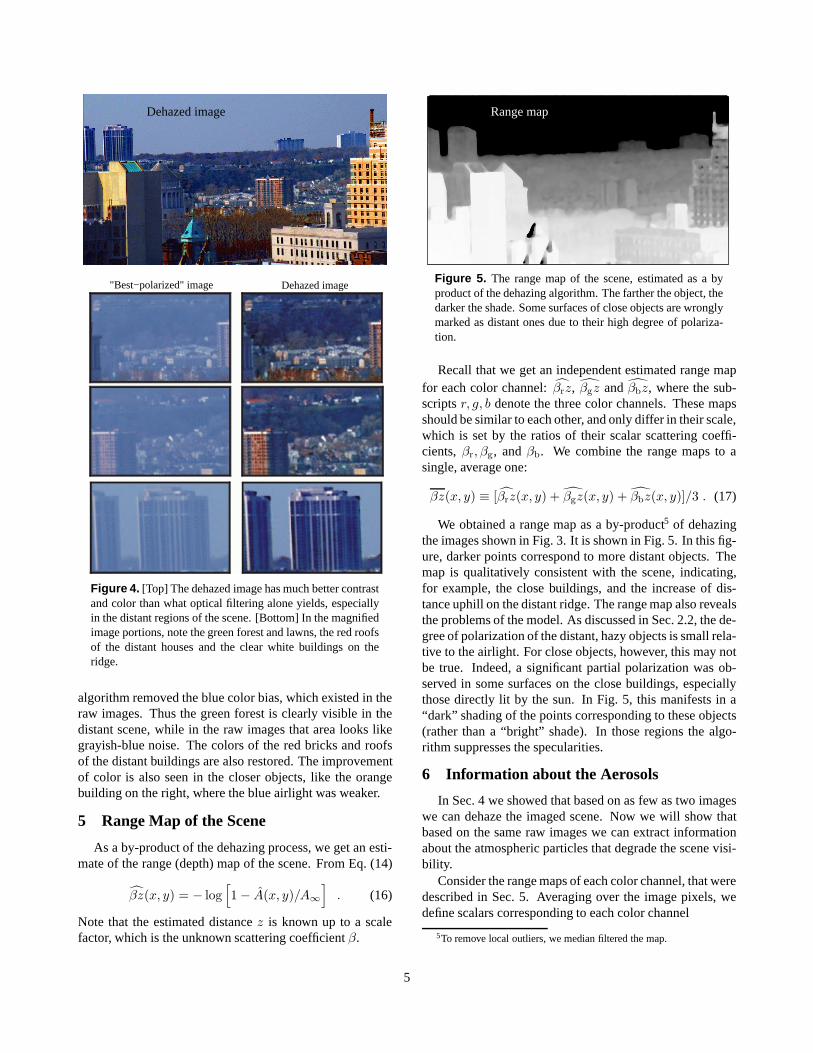
We applied these results to the images shown in Fig. 3.The resulting dehazed image3 is shown in Fig. 4. The inten-sity of the displayed image has the same scale as was usedwhen displaying4 the “best polarized” imageI‖ on the bot-tom of Fig. 3. The contrast of features in the dehazed imageis greatly improved relative toI‖ andI⊥. Moreover, the
3We did not apply the dehazing technique to the sky area. The reason isthat the model assumes the sky to be at infinity, and thus there is no objectto recover.
4As in the images shown in Fig. 3, only the intensity is scaled for thedisplay, and the hue and saturation are not processed.
4
Dehazed image"Best−polarized" image
Dehazed image
Figure 4. [Top] The dehazed image has much better contrastand color than what optical filtering alone yields, especiallyin the distant regions of the scene. [Bottom] In the magnifiedimage portions, note the green forest and lawns, the red roofsof the distant houses and the clear white buildings on theridge.
algorithm removed the blue color bias, which existed in theraw images. Thus the green forest is clearly visible in thedistant scene, while in the raw images that area looks likegrayish-blue noise. The colors of the red bricks and roofsof the distant buildings are also restored. The improvementof color is also seen in the closer objects, like the orangebuilding on the right, where the blue airlight was weaker.
5 Range Map of the Scene
As a by-product of the dehazing process, we get an esti-mate of the range (depth) map of the scene. From Eq. (14)
βz(x, y) = − log[1 − A(x, y)/A∞
]. (16)
Note that the estimated distancez is known up to a scalefactor, which is the unknown scattering coefficientβ.
Range map
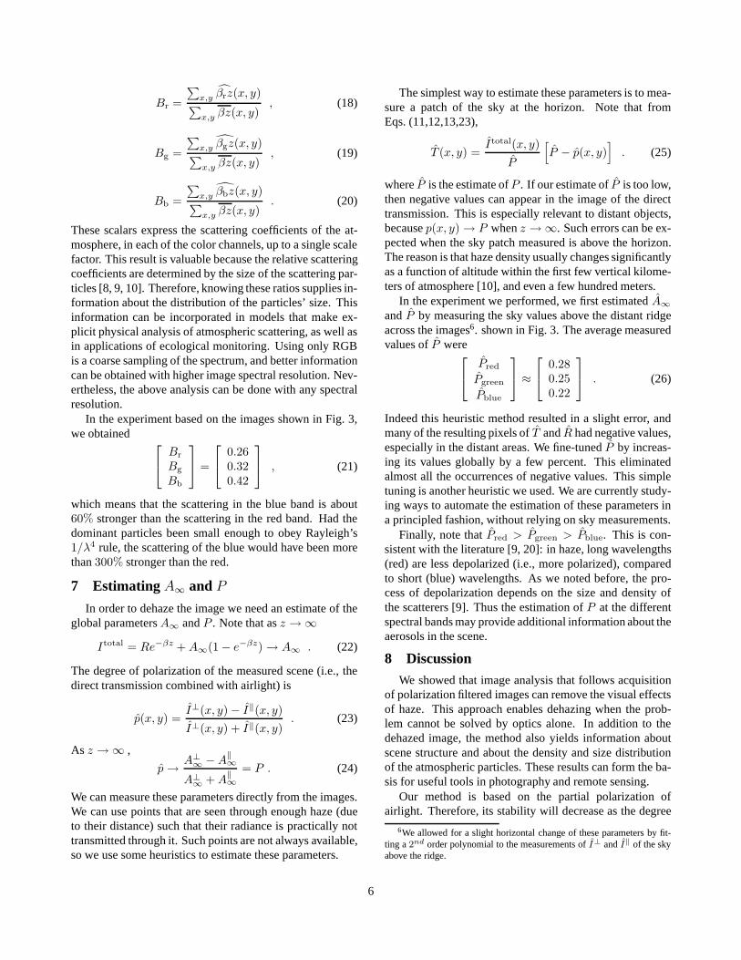
Figure 5. The range map of the scene, estimated as a byproduct of the dehazing algorithm. The farther the object, thedarker the shade. Some surfaces of close objects are wronglymarked as distant ones due to their high degree of polariza-tion.
Recall that we get an independent estimated range mapfor each color channel:βrz, βgz andβbz, where the sub-scriptsr, g, b denote the three color channels. These mapsshould be similar to each other, and only differ in their scale,which is set by the ratios of their scalar scattering coeffi-cients,βr, βg, andβb. We combine the range maps to asingle, average one:
βz(x, y) ≡ [βrz(x, y) + βgz(x, y) + βbz(x, y)]/3 . (17)
We obtained a range map as a by-product5 of dehazingthe images shown in Fig. 3. It is shown in Fig. 5. In this fig-ure, darker points correspond to more distant objects. Themap is qualitatively consistent with the scene, indicating,for example, the close buildings, and the increase of dis-tance uphill on the distant ridge. The range map also revealsthe problems of the model. As discussed in Sec. 2.2, the de-gree of polarization of the distant, hazy objects is small rela-tive to the airlight. For close objects, however, this may notbe true. Indeed, a significant partial polarization was ob-served in some surfaces on the close buildings, especiallythose directly lit by the sun. In Fig. 5, this manifests in a“dark” shading of the points corresponding to these objects(rather than a “bright” shade). In those regions the algo-rithm suppresses the specularities.
6 Information about the Aerosols
In Sec. 4 we showed that based on as few as two imageswe can dehaze the imaged scene. Now we will show thatbased on the same raw images we can extract informationabout the atmospheric particles that degrade the scene visi-bility.
Consider the range maps of each color channel, that weredescribed in Sec. 5. Averaging over the image pixels, wedefine scalars corresponding to each color channel
5To remove local outliers, we median filtered the map.
5
Br =
∑x,y βrz(x, y)∑x,y βz(x, y)
, (18)
Bg =
∑x,y βgz(x, y)∑x,y βz(x, y)
, (19)
Bb =
∑x,y βbz(x, y)∑x,y βz(x, y)
. (20)
These scalars express the scattering coefficients of the at-mosphere, in each of the color channels, up to a single scalefactor. This result is valuable because the relative scatteringcoefficients are determined by the size of the scattering par-ticles [8, 9, 10]. Therefore, knowing these ratios supplies in-formation about the distribution of the particles’ size. Thisinformation can be incorporated in models that make ex-plicit physical analysis of atmospheric scattering, as well asin applications of ecological monitoring. Using only RGBis a coarse sampling of the spectrum, and better informationcan be obtained with higher image spectral resolution. Nev-ertheless, the above analysis can be done with any spectralresolution.
In the experiment based on the images shown in Fig. 3,we obtained
Br
Bg
Bb
=
0.26
0.320.42
, (21)
which means that the scattering in the blue band is about60% stronger than the scattering in the red band. Had thedominant particles been small enough to obey Rayleigh’s1/λ4 rule, the scattering of the blue would have been morethan300% stronger than the red.
7 Estimating A∞ and P
In order to dehaze the image we need an estimate of theglobal parametersA∞ andP . Note that asz → ∞
Itotal = Re−βz + A∞(1 − e−βz) → A∞ . (22)
The degree of polarization of the measured scene (i.e., thedirect transmission combined with airlight) is
p(x, y) =I⊥(x, y) − I‖(x, y)I⊥(x, y) + I‖(x, y)
. (23)
As z → ∞ ,
p → A⊥∞ − A
‖∞
A⊥∞ + A‖∞
= P . (24)
We can measure these parameters directly from the images.We can use points that are seen through enough haze (dueto their distance) such that their radiance is practically nottransmitted through it. Such points are not always available,so we use some heuristics to estimate these parameters.
The simplest way to estimate these parameters is to mea-sure a patch of the sky at the horizon. Note that fromEqs. (11,12,13,23),
T (x, y) =Itotal(x, y)
P
[P − p(x, y)
]. (25)
whereP is the estimate ofP . If our estimate ofP is too low,then negative values can appear in the image of the directtransmission. This is especially relevant to distant objects,becausep(x, y) → P whenz → ∞. Such errors can be ex-pected when the sky patch measured is above the horizon.The reason is that haze density usually changes significantlyas a function of altitude within the first few vertical kilome-ters of atmosphere [10], and even a few hundred meters.
In the experiment we performed, we first estimatedA∞andP by measuring the sky values above the distant ridgeacross the images6. shown in Fig. 3. The average measuredvalues ofP were
Pred
Pgreen
Pblue
≈
0.28
0.250.22
. (26)
Indeed this heuristic method resulted in a slight error, andmany of the resulting pixels ofT andR had negative values,especially in the distant areas. We fine-tunedP by increas-ing its values globally by a few percent. This eliminatedalmost all the occurrences of negative values. This simpletuning is another heuristic we used. We are currently study-ing ways to automate the estimation of these parameters ina principled fashion, without relying on sky measurements.
Finally, note thatPred > Pgreen > Pblue. This is con-sistent with the literature [9, 20]: in haze, long wavelengths(red) are less depolarized (i.e., more polarized), comparedto short (blue) wavelengths. As we noted before, the pro-cess of depolarization depends on the size and density ofthe scatterers [9]. Thus the estimation ofP at the differentspectral bands may provide additional information about theaerosols in the scene.
8 DiscussionWe showed that image analysis that follows acquisition
of polarization filtered images can remove the visual effectsof haze. This approach enables dehazing when the prob-lem cannot be solved by optics alone. In addition to thedehazed image, the method also yields information aboutscene structure and about the density and size distributionof the atmospheric particles. These results can form the ba-sis for useful tools in photography and remote sensing.
Our method is based on the partial polarization ofairlight. Therefore, its stability will decrease as the degree
6We allowed for a slight horizontal change of these parameters by fit-ting a2nd order polynomial to the measurements ofI⊥ andI‖ of the skyabove the ridge.
6
of polarization decreases. For instance, the method may beless effective under an overcast sky. The method may fail insituations of fog or very dense haze.
We are currently studying the effects of polarization inmore complicated weather conditions such as fog or rain.Interestingly, the airlight in rain is partially polarized, andthus rainbows can be significantly enhanced or suppressedusing a polarizer [9]. It is possible that this work can be ex-tended to other scattering media. Examples for such mediaare underwater environments (where the ambient illumina-tion is partially polarized [26]), or even tissues (e.g., skin).
AcknowledgmentsThis work was supported in parts by a grant
from DARPA’s Human Identification at a Distance pro-gram, award# N00014-00-1-0916, by the NSF awardIIS-99-87979, and by the Morin Foundation.
A AppendixA.1 Using Arbitrary 2 Images
In Sec. 4,5 we used estimates ofI‖ andI⊥ in the de-hazing algorithm. We now show that in theory the methodcan work based on two images taken at almost any differentpolarization orientations. Letθ‖ be the orientation of thepolarizer for best transmission of the component parallel tothe plane of incidence (Fig. 1). For a general orientationα,the observed airlight is
A(α) = A{1 − P cos[2(α − θ‖)]
}/2 , (27)
which coincides with Eqs. (7,9) ifα = θ‖, θ‖ + 90o. Sup-pose we take two images of the scene with arbitrary ori-entations of the polarizer,α1 6= α2. Because the directtransmission is unaffected by the polarizer orientation, theimages are
I1 = T/2 + A(α1) (28)and
I2 = T/2 + A(α2) . (29)
Let us define an effective airlight
Aeffective ≡ A(α1) + A(α2), (30)
with an effective degree of polarization
Peffective ≡ A(α2) − A(α1)Aeffective
, (31)
where we setA(α2) ≥ A(α1), without loss of generality.We also define an effective unfiltered image
Itotaleffective ≡ I1 + I2 = T + Aeffective. (32)
It can easily be shown thatAeffective is proportional to theactual airlight,
Aeffective = fA = fA∞(1−e−βz) = Aeffective∞ (1−e−βz) ,
(33)
whereAeffective∞ is the effective airlight at infinity (the hori-
zon). The proportion factorf is
f = 1 − P cos(α1 + α2 − 2θ‖) cos(α1 − α2) . (34)
Because wedo not knowθ‖ based on two arbitrary polarizerangles,f is unknown.
Suppose now that we have estimates of the parametersPeffective andAeffective∞ . These parameters can be estimatedby measuring the sky intensities ofI1 andI2, similar to theway described in Sec. 7. Then, we estimate the effectiveairlight at each point
Aeffective =I2 − I1
Peffective. (35)
From Eq. (32), the estimated direct transmission based onthe raw imagesI1 andI2 is
T = Itotaleffective − Aeffective . (36)
From Eq. (33) the estimated attenuation is
e−βz = 1 − Aeffective
Aeffective∞, (37)
thus the dehazed image is
R =Itotaleffective − Aeffective
1 − Aeffective/Aeffective∞. (38)
We can check the stability of using an arbitrary pair ofimages. It is easy to show that
Peffective =AP
Aeffectivesin(α1 + α2 − 2θ‖) sin(α2 − α1) .
(39)Eq. (35) becomes unstable whenPeffective → 0. Beside theobvious case in whichP = 0, this happens when
α1 + α2
2= θ‖, θ‖ + 90o . (40)
This is expected because the acquired images are equal iftaken on symmetric angles relative to the extrema of thecosine in Eq. (27). Therefore, changing the orientation fromα1 to α2 is degenerate. Except for these singular cases,dehazing is possible using two images. The best stabilityof dehazing is achieved whenPeffective is maximum, that is,whenα = θ‖, θ‖ + 90o. Therefore, our the paper focuseson dehazing based onI‖ andI⊥. The estimation of theseimages is discussed in the next section.
A.2 Using More than 2 ImagesAs mentioned above, the method works best withI‖ and
I⊥. By rotating the polarizer to achieve an extremum ofthe intensity or contrast, it is often easy to visually detectthe states corresponding to these components. However, itis easier and more accurate to estimate these componentsusingthreeor more images taken through different generalorientations of the polarizer. This is a common practice inpolarization imaging [13, 19, 21, 22, 26].
7

Let θ‖ be the orientation of the polarizer for best trans-mission of the component parallel to the plane of incidence(see Figs. 1,2). For a general orientationα, the observedintensity at each pixel is
I(α) = (1/2)Itotal − a cos[2(α − θ‖)] (41)
where a is the amplitude of the modulation caused bychanging the filter’s orientation.
We can write Eq. (41) for an angleαk as
[1/2 − cos(2αk) − sin(2αk)]
Itotal
acos
asin
= Ik ,
(42)whereacos = a cos(2θ‖) andasin = a sin(2θ‖). To obtain
the estimatesItotal, acos and asin, three linearly indepen-dent measurements are sufficient. If we have more than 3measurements, we derive the least squares estimates. Then,we find the image components as
I‖ = (1/2)Itotal − a (43)
andI⊥ = (1/2)Itotal + a , (44)
where a =√
a2cos + a2
sin . These equations also yield anestimate ofθ‖ at each pixel:
θ‖ = (1/2) arctan(asin/acos) . (45)
The images shown in Fig. 3 were actually estimated thisway, based on photographs taken at 4 different polarizer ori-entations. The photographs were linearized to compensatefor the detector’s radiometric response. The response wasestimated from images of the Macbeth ColorChecker [5].We obtained high dynamic range images by weighted aver-aging of multiple exposures.
References[1] M. Ben-Ezra, “Segmentation with invisible keying signal,”
Proc. CVPR, pp. 32-37 (2000).
[2] C. F. Bohren, “Maximum degree of polarization of the resul-tant of two partially polarized incoherent beams,” App. Opt.26, pp. 606-607 (1987).
[3] S. Chandrasekhar,Radiative transfer, pp. 24-37,280-284(Dover, New York, 1960).
[4] F. Cozman and E. Krotkov, “Depth from scattering,”Proc.CVPR, pp. 801-806 (1997).
[5] A. S. Glassner,Principles of digital image synthesis, Ap-pendix G.4 (Morgan-Kaufmann, 1995).
[6] L. Grewe and R. R. Brooks, “Atmospheric attenuation re-duction through multi-sensor fusion,” Proc. SPIE3376, Sen-sor fusion: Architectures, algorithms, and Applications II,pp. 102-109 (1998).
[7] H. Farid and E. H. Adelson, “Separating reflections andlighting using independent components analysis,” Proc.CVPR pp. 262-267 (1999).
[8] E. Hecht, Optics, 3rd Ed., pp. 340-342 (Addison-Wesley,New-York, 1998).
[9] G. P. Konnen,Polarized light in nature,pp. 1-10,29-54,60-62,131-137,144-145 (Cambridge University Press, Cam-bridge, 1985).
[10] N. S. Kopeika,A system engineering approach to imaging,pp. 446-452 (SPIE Press, Bellingham 1998).
[11] S. G. Narasimhan and S. K. Nayar “Chromatic frameworkfor vision in bad weather,” Proc. CVPR, pp. 598-605 (2000).
[12] S. G. Narasimhan and S. K. Nayar “Removing weather ef-fects from monochrome images,” in these Proceedings ofCVPR (2001).
[13] S. K. Nayar, X. S. Fang and T. Boult, “Separation of reflec-tion components using color and polarization,” Int. J. Comp.Vis. 21, pp. 163-186 (1997).
[14] S. K. Nayar and S. G. Narasimhan, “Vision in bad weather,”Proc. ICCV, pp. 820-827 (1999).
[15] J. P. Oakley, and B. L. Satherley “Improving image qualityin poor visibility conditions using a physical model for con-trast degradation,”IEEE Trans. Imag. Proc.7, pp. 167-179(1998).
[16] P. Pencipowski, “A low cost vehicle-mounted enhanced vi-sion system comprised of a laser illuminator and range-gatedcamera,” Proc. SPIE2736 Enhanced and synthetic vision,pp. 222-227 (1996).
[17] M. Saito, Y. Sato, K. Ikeuchi, and H. Kashiwagi, “Mea-surement of surface orientations of transparent objects usingpolarization in highlight,” Proc. CVPR, Vol. I, pp. 381-386(1999).
[18] Y. Y. Schechner, J. Shamir and N. Kiryati “Polarization-based decorrelation of transparent layers: The inclinationangle of an invisible surface,” Proc. ICCV, pp. 814-819(1999).
[19] Y. Y. Schechner, J. Shamir and N. Kiryati “Polarization andstatistical analysis of scenes containing a semi-reflector,”JOSA-A17, pp. 276-284 (2000).
[20] W. A. Shurcliff and S. S. Ballard,Polarized light, pp. 98-103(Van Nostrand Co., Princeton, 1964).
[21] A. M. Shutov, “Videopolarimeters,” Sov. J. Opt. Technol.60, pp. 295-301 (1993).
[22] J. E. Solomon, “Polarization imaging,” App. Opt.20,pp. 1537-1544 (1981).
[23] B. T. Sweet and C. Tiana “Image processing and fusion forlanding guidance,” Proc. SPIE2736Enhanced and syntheticvision,pp. 84-95 (1996).
[24] K. Tan and J. P. Oakley, “Enhancement of color images inpoor visibility conditions,” Proc. ICIP pp. 788-791 (2000).
[25] L. B. Wolff, “Using polarization to separate reflection com-ponents,” Proc. CVPR, pp. 363-369 (1989).
[26] L. B. Wolff, “Polarization vision: a new sensory approachto image understanding,” Image and Vision Computing15,pp. 81-93 (1997).
8