installed soil nails a thesis the requirements for the
TRANSCRIPT

INFLUENCE OF GROUT MIX DESIGN AND PLACEMENT
PROCEDURES ON THE INTEGRITY OF
INSTALLED SOIL NAILS
by
JOHN B. TURNER, B.S.
A THESIS
IN
CIVIL ENGINEERING
Submitted to the Graduate Faculty
of Texas Tech University in Partial Fulfillment of the Requirements for
the Degree of
MASTER OF SCIENCE
IN
CIVIL ENGINEERING
A rtrxrnvt'A
Char^crsoii oT t'he Committee
—I T-
Accepted
-y-m w
Dean of the Graduate School
December, 2004

Copyright 2004, John B. Turner, Jr.
CONTENTS
ABSTRACT ^
TABLES .^j
FIGURES .^ii
CHAPTER
1 B.ACKGROUND .AND PROBLEM DEFINITION 1
1.1 Relevant Issues in Soil Nailing 2
1.1.1 Grout 3
1.1.2 Centralizers 4
1.1.3 Grout placement 5
1.2 Special Considerations 7
1.2.1 Tremie pipe use 7
1.2.2 Timing of grout placement 7
1.2.3 Grout subsidence 7
1.2.4 Grout bond 8
1.2.5 Special design 9
1.3 Reason For Investigation 9
1.3.1 Failure and mechanisms 9
1.3.2 Failure experience 10
1.4 Control of Grout Defect Failure Mechanisms 10
2 INITIAL INVESTIGATION 12
2.1 Literature Search 12
2.2 Contractor Survey 13
2.2.1 Grout 14
2.2.2 Tendons 15
m
2.2.3 Tremie use and tendon insertion 15
2.2.4 Borehole diameter 16
2.2.5 Personnel 17
3 DESIGN OF E.\PERIMENT AND COMPLETION OF EXPERIMENTAL TESTING 18
3.1 Experimental Purpose 18
3.2 Experimental Test Design 18
3.2.1 Tremie length 20
3.2.2 Grout consistency 20
3.2.3 Grout aggregates 21
3.3 Testbed 22
3.4 Experimental Parameters and Grout Placement 25
3.4.1 Variation of tremie 25
3.4.2 Variation of grout and test methods 26
3.5 Testbed Installation 27
3.4 Experimental Results 32
3.5 Laboratory Testing 36
3.6 Interpretation of Testbed Results 36
4 FULL SCALE FIELD TEST 38
4.1 Preparation and Installation 38
4.2 Inspection 39
4.3 Exhumation and Examination 41
4.4 Analysis 42
5 DISCUSSION OF RESULTS AND RECOMMENDATIONS 44
5.1 Effect of Tremie Insertion 44
5.2 Grout Rheology 45
IV

5.3 Grout Composition 45
5.4 Conclusions 46
5.5 Suggested Specifications 47
REFERENCES 49

ABSTRACT
The evolution of methods to stabilize vertical soil walls includes a
technique referred to as soil nailing. This technique utihzes steel tendons
embedded in cementitious grout to bind a consolidated soil mass together
sufficientl> to prevent sloughing of the soil mass as its face is excavated. This
thesis summarizes an effort to determine the factors related to the grout and its
installation which affect wall stabihty. This research found that proper
installation of grout materials will occur only where the grout is placed using a
tremie pipe or grout tube which reaches the full length of the soil nail tendon.
Additionall>, this study shows that grout consistency can be selected to suit the
installer and that, installed properly, any grout of sufficient strength which can
be pimiped using a general purpose concrete or grout pump should properly fill
the soil nail borehole and embed the tendon.
VI
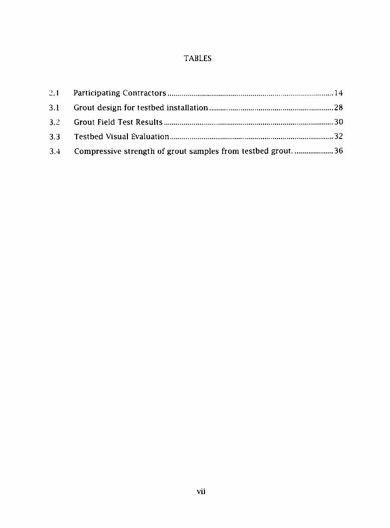
TABLES
2.1 Participating Contractors 14
3.1 Grout design for testbed installation 28
3.2 Grout Field Test Resuhs 30
3.3 Testbed Visual Evaluation 32
3.4 Compressive strength of grout samples from testbed grout 36
Vll
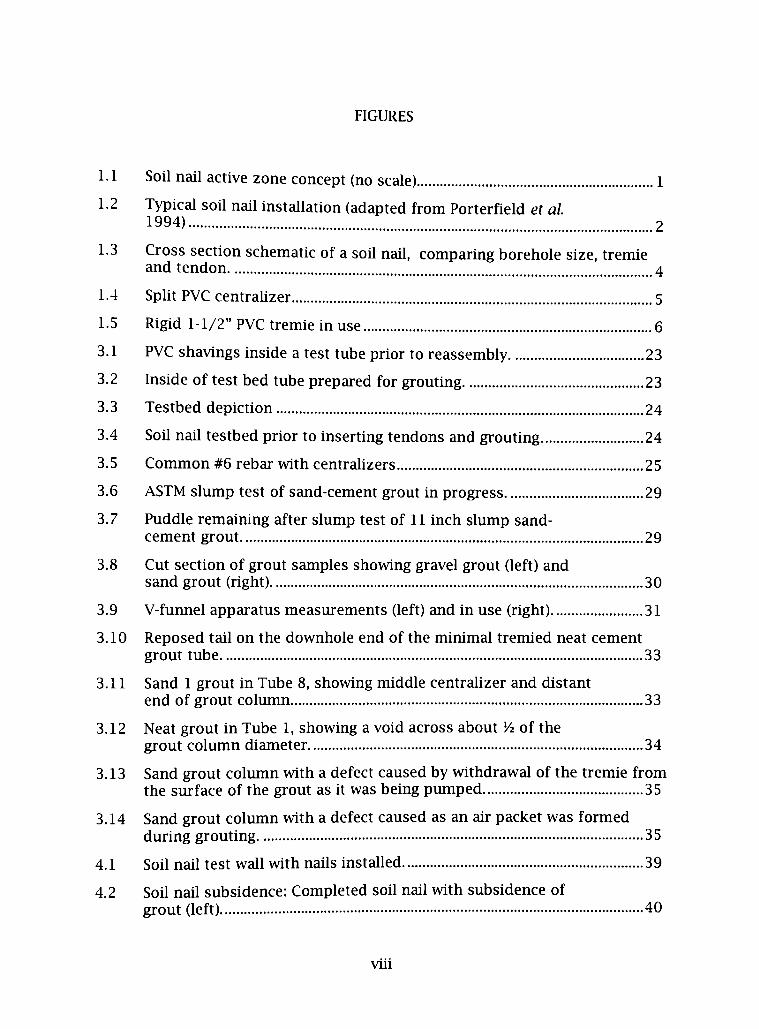
FIGURES
1.1 Soil nail active zone concept (no scale) 1
1.2 Typical soil nail installation (adapted from Porterfield et al. 1994) 2
1.3 Cross section schematic of a soil nail, comparing borehole size, tremie and tendon 4
1.4 Split PVC centralizer 5
1.5 Rigid 1-1/2" PVC tremie in use 6
3.1 PVC shavings inside a test tube prior to reassembly 23
3.2 Inside of test bed tube prepared for grouting 23
3.3 Testbed depiction 24
3.4 Soil nail testbed prior to inserting tendons and grouting 24
3.5 Conmion #6 rebar with centralizers 25
3.6 ASTM slirnip test of sand-cement grout in progress 29
3.7 Puddle remaining after slump test of 11 inch slump sand-cement grout 29
3.8 Cut section of grout samples showing gravel grout (left) and sand grout (right) 30
3.9 V-fuimel apparatus measurements (left) and in use (right) 31
3.10 Reposed tail on the downhole end of the minimal tremied neat cement grout tube 33
3.11 Sand 1 grout in Tube 8, showing middle centralizer and distant end of grout colimin 33
3.12 Neat grout in Tube 1, showing a void across about Vi of the grout column diameter 34
3.13 Sand grout colimin with a defect caused by withdrawal of the tremie from the surface of the grout as it was being pumped 35
3.14 Sand grout colimin with a defect caused as an air packet was formed during grouting 35
4.1 Soil nail test wall with nails installed 39
4.2 Soil nail subsidence: Completed soil nail with subsidence of grout (left) 40
viu
4.3 Excavated soil nail showing grout plug and centralizer 41
4.4 Excavated soil nail showing plug in an open bore 42
IX
CHAPTER 1
BACKGROUND AND PROBLEM DEFINITION
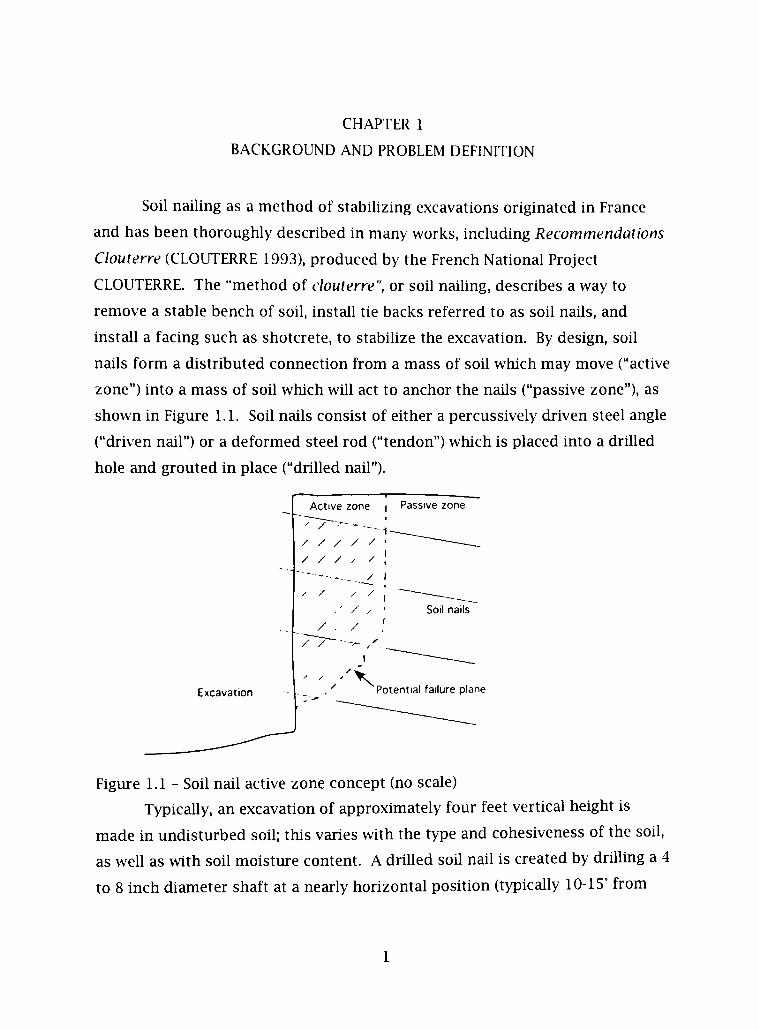
Soil naihng as a method of stabihzing excavations originated in France
and has been thoroughly described in many works, including Recommendations
Clouterre (CLOUTERRE 1993), produced by the French National Project
CLOUTERRE. The "method of clouterre", or soil naihng, describes a way to
remove a stable bench of soil, install tie backs referred to as soil nails, and
install a facing such as shotcrete, to stabihze the excavation. By design, soil
nails form a distributed connection from a mass of soil which may move ("active
zone") into a mass of soil which will act to anchor the nails ("passive zone"), as
shown in Figure 1.1. Soil nails consist of either a percussively driven steel angle
("driven nail") or a deformed steel rod ("tendon") which is placed into a drilled
hole and grouted in place ("drilled nail").
Excavation
Active zone i Passive zone
/ / / / / / / /
/ .
_ _ / I
Soli nails
X Potential failure plane
Figure 1.1 - Soil nail active zone concept (no scale)
Typically, an excavation of approximately four feet vertical height is
made in undisturbed soil; this varies with the type and cohesiveness of the soil,
as well as with soil moisture content. A drilled soil nail is created by drilling a 4
to 8 inch diameter shaft at a nearly horizontal position (typically 10-15° from

horizontal, angled downward from the open end), placing a central tendon of
deformed steel rod in the shaft, and filling the annulus with cementitious grout.
As each successive excavation level is stabihzed, further excavation is
undertaken until a stable wall of virtually any height is completed. Figure 1.2
shows a schematic of a typical soil nail. It is the grout placed into the annular
space around tendon which is the subject of this thesis.
• PERMANENT FACING (CIP CONCRETE/SHOTCRETE)
TEMPORARY FACING (SHOTCRETE)
GEOCOMPOSITE STRIP DRAIN
BEARING PLATE
BEARING NUT AND
BEVELED WASHER
HEADED STUD (TYP)
REINFORCEMENT DRILLHOLE
Source: Porlerfield tV^/ (1994).
Figure 1.2 - Typical soil nail installation (adapted from Porterfield et al. 1994)
1.1 Relevant Issues in Soil Naihng
The decision to use drilled soil nails as the method for stabihzation
typically falls on three main issues. First, soil naihng is best suited for
undisturbed soils and compacted soU masses which have consohdated under
static weight for some period of time. Other methods such as mechanicaUy-
stabihzed earth (MSE) would be preferred for newly filled areas. Second, soil
nail methods are suitable for many soil types except cohesionless materials

such as gravel and sand. The borings made to place soil nails require cohesive
soil and an expectation that the completed nail will have good resistance to
\vithdrawal. The placement of grout through hollow stem augers allows
placement in unstable materials, however free-flowing soils typically are
unsuitable since loose material will flow onto the auger as drilling progresses.
Material flow makes the small diameter boring into a sizable excavation and the
resulting nail may have little resistance to movement. Finally, soil nail
mstallation is used where cost efficiency is important and as such, the profit on
most installations is small, making minor inefficiencies very important.
1.1.1 Grout
The grout material performs two functions, namely protecting the steel
tendon from corrosion, and bonding of the tendon into the soil mass. The
tendon must be fully encapsulated and must have sufficient cover, particularly
in aggressive soils. Typical steel reinforced concrete design requires a minimmn
of three (3) inches of cementitious material between reinforcement and adjacent
soil ("clear cover") (ACI 318-02 § 1.1), however this is not feasible in most soil
nails. In order to estabhsh good corrosion protection in permanent soil nail
installations, alternative measure to prevent corrosion is required. There is no
concrete industry code or practice, or other specifically-apphcable requirement,
since the structural nature of soil nails differs from typical reinforced concrete
structm-es. With the cementitious grout acting as the primary protection, a
barrier layer formed by either a grouted tendon duct or epoxy coating helps
protect the tendon as the grout cracks or where cover is thin.
Figure 1.3 depicts an overlay of typical soil nail diameters, shown with a
central tendon and tremie sizes. The space available within two sizes of borings
can be compared. The tendon is the tensile load carrying portion of the soil
nail, which also provides shear resistance; the tendon is generally a % to 1 V*
mch diameter steel bar. The tremie is a pipe or tube through which grout is
pimiped, aUowing the grout to be placed throughout the length of the borehole.
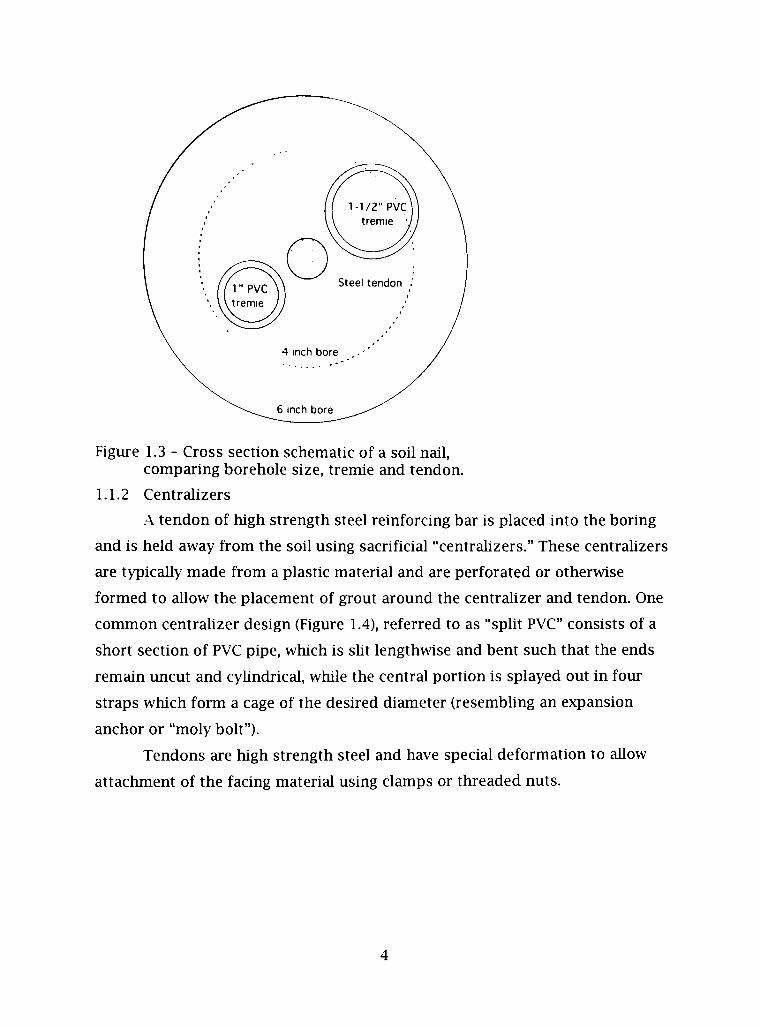
Figure 1.3 - Cross section schematic of a soil nail, comparing borehole size, tremie and tendon.
1.1.2 Centralizers
.A tendon of high strength steel reinforcing bar is placed into the boring
and is held away from the soil using sacrificial "centralizers." These centrahzers
are typically made from a plastic material and are perforated or otherwise
formed to aUow the placement of grout around the centralizer and tendon. One
common centrahzer design (Figure 1.4), referred to as "split PVC" consists of a
short section of PVC pipe, which is sht lengthwise and bent such that the ends
remain tincut and cyhndrical, while the central portion is splayed out in four
straps which form a cage of the desired diameter (resembhng an expansion
anchor or "moly bolt").
Tendons are high strength steel and have special deformation to aUow
attachment of the facing material using clamps or threaded nuts.

1.1.3 Grout placement
Grout is then placed into the boring through a tremie, either a flexible
tube or rigid pipe. (Figure 1.5) The grout is supplied through the tremie at the
low est pressure required to induce grout flow into the borehole.
Figure 1.4 • Spht P\ C centrahzer
Most modern installations are completed using either special grout
pumps which do not pimip grouts containing aggregates, or standard trailer-
type concrete pimips, most of which are capable of pumping 1-1/2 inch
aggregates in concrete mixtures up to about an eight inch (20 cm) slimip (as
determined by ASTM C143). Although not covered in this thesis, grout may also
be placed under higher pressures in order to cause exfiltration of grout into the
surrounding soil, as a method of improving bonding with the soil and
stabihzing the soil mass. This method is not covered by this thesis since such
installations require highly fluid grouts and speciahzed equipment, and are
uncommon in the United States.
Some installations, such as those in low-cohesion or wet soils, require the
placement of grout prior to tendon placement. Grouting in these cases may be
completed using hollow-stem augers or by placing grout using a standard tremie
pipe after the auger is removed. The tendon is fitted with centralizers and
inserted into the boring which has been filled completely with grout. Some

equipment may also permit the insertion of the tendon through the hollow auger.
Figure 1.5 - Rigid 1-1/2" PVC tremie in use
The placement of grout into the annular space of the soil nail boring after
tendon placement creates certain restrictions on the materials that can be
chosen for such a use. As mentioned previously. Figure 1.3 depicts tremie sizes
relative to borehole size and a central tendon. Depending on the boring and
tendon diameter, the annular space may be very small. For the most restrictive
installations, [four inch (10 cm) diameter borings with a single one inch (25 mm)
tendon and split-PVC centrahzers] space is available for a grout tube or tremie
with an outside diameter of no larger than one inch (25 mm). Alternatively, the
grout can be placed before the tendon in inserted. In either case, highly fluid
grouts must be used and great care must be taken to prevent entrairmient of
loose soil or otherwise create imperfections in the grout column. In larger
diameter bores (6-8 inch), larger tremies and stiffer grout can be used.

1.2 Special Considerations
1.2.1 Tremie pipe use
The placement of grouts where the water table or other conditions cause
water to collect into the driUed soil nail borings requires special attention and
precautions to assure that the grout retains its design shape and length, without
serious imperfections or inclusions, and that grout strength is maintained in the
presence of the collected water. The primary grouting method in such
installations is the placement of the tremie tube or pipe to the full boring depth
(beyond the end of the steel tendon) and pumping of grout continuously until
grout of the proper appearance flows from the mouth of the boring; grout is
then pumped continuously as the tremie is withdrawn from the soil nail. It is
also Ukel> that conditions may require the withdrawal of the tremie as grout is
placed; so long as the tremie remains inside the grout mass, this is generally
considered acceptable by contractors and is in accordance with Federal
Highways Administration (FHWA) guidehnes:
...the grouting operation involves injecting grout at the lowest point of the drill hole in order to fill the hole evenly without air voids (i.e., via a tremie pipe)... The grout should flow continuously as the tremie pipe is withdrawn. The withdrawal rate should be controlled to ensure that the end of the tremie pipe is always below the grout surface. A record of the volume of grout placed should be maintained. (Lazarte et al., 2003)
1.2.2 Timing of grout placement
Many soil nail specifications require that the tendon be grouted into the
boring within twenty-four hours of drilhng; some soil conditions may reqture
more restrictive guidance, such as requiring grouting within the same shift or
during the same day as drilhng. This short interval reduces the risk of soil
caving or the collecting of water into the boring. FHWA states that generally,
drilhng and placement should occur during a single shift. (Lazarte et al, 2003)
1.2.3 Grout subsidence
The type of grout selected, the surrounding soil characteristics, and the
smoothness and inchnation of the borehole, may contribute to subsidence of
the grout column. This can be due to expression or bleeding of water and
cement-water "cream" into surrounding soil, grout shrinkage, escape of
entrapped air, and other mechanisms. Soil nail contractors frequently expect
such results and provide for "topping off" of the grout. Some installations also
utihze "regrout" pipes which allow the placement of grout under gravity or
pressure into any voids and may be designed to fracture the first grout and
expand it into the soil mass. Pressure regrouting is not commonly used in the
United States and is not discussed further here, just as it is explicitly omitted in
FHW.A pubhcations.
1.2.4 Grout bond
Bonding between the grout colmnn and the tendon is typically not a limit
in design, however it can be accepted that adequate bonding is achieved over
the length of the tendon by using ACI 318 provisions for reinforcement
development length or as otherwise specified by the bar manufacturer (for
specially deformed bars). Depending on typical service conditions, soil nail
length is designed primarily for bond with the soil and the assimied active
zone/passive zone interface (Figure 1.1).
Bond between the soil mass and the grout coltmm may be affected by the
grout type, however, other factors such as irregularities in the boring and
changes in soil type over the length of the soil nail play a much greater role in
this bond. In agreeing with this comment, FHWA-IP-03-017 goes on to state that
there is "httle benefit in pressure grouting fine-grained soil installations". The
soil nail designer may specify a special grout, or may accept that any grout that
meets the strength requirements is acceptable. As a minimum, a soil nail grout
design requires that the grout must properly consohdate onto the tendon and
into the surrounding soil under gravity head, providing the design bond. This
thesis does not cover conditions where special grout bond or strength
requirements have been identified and have been included in a specific grout
design.
1.2.5 Special design
Other conditions may e>dst either in situ, or have been postulated in
design, which require special grout or grouting methods. These conditions may
include low cohesion materials, e.xcessively dry or moist soils, extremes of
temperature during placement or curing, and other sub-optimal conditions.
Where such prov isions have been identified, the designer must justify deviation
from accepted practice.
1.3 Reason For Investigation
1.3.1 Failure and mechanisms
The failm-e rate for driUed soil nails (as opposed to percussively driven
soil nails, "method of Hurpm") is very low. {Recommendations Clouterre 1991,
Chapter I, 1.0) (Schlosser et al, 1991) Where failures have been investigated, the
failures can be considered in categories that express the mechanism of failure.
Most failures are quantitative failm-es, which are not readily apparent to
passersby, and the failure mode is gradual deformation, either during or after
construction. In contrast to this, where poor cohesion or grossly inadequate
design or faulty construction are responsible, the failure may be sudden and
catastrophic. Catastrophic failm-es also occur where the soil mass reduces
cohesion suddenly, such as by saturation or seismic liquefaction.
Recommendations Clouterre and various US DOT pubhcations identify these
internal and external failures and designers must consider them in design.
Failures may also be classified by the mechanism that permits the
deformity or rupture. Recommendations Clouterre notes some of these
mechanisms and discusses their causes. It should be noted that a failure
relating to the grout material or placement might occur regardless of, or in
combination with, other factors. This thesis explores factors related to the
grout materials and placement, which could result in insufficient installation of
the grout, such as voids and inclusions in the grout colimin occurring during
nail or grout installation, or arising from events or conditions during drilhng.

1.3.2 Failure experience
According to various contractors and the Texas Department of
Transportation, soil nail failures on highway projects have been few, and
grouting problems have generally been identified following pullout strength
tests, before the installation is completed. A "typical" failure under load test
occurs when a soil nail > ields at a load below the ultimate design load; these
failures are e.xhumed and typically have defects in the grout column or have
unexpected soil conditions.
One failure identified by an experienced contractor, involved stiff grout,
which tested to 7 inch slump using ASTM C143 methods. A single nail failed
under test and was found to have defects in the grout column after exhumation.
The assessment of TxDOT officials was that the grout defect was the result of
the excessively stiff grout being unable to fiU the borehole and properly
consohdate onto the tendon.
According to TxDOT, the only notable service failure seen on a highway
project in the state occurred in the Dallas area. In this installation, the defect
was only identified following catastrophic failure. The grout columns had been
filled partially throughout their length and tendons were only partially
imbedded in the grout. Investigation found that the installer had used a
shotcrete pump and no tremie to install the grout. This demonstrated well the
nature of potential soil naU grouting defects arising from poor installation
practices, and is much of the reason for the project leading this thesis.
1.4 Control of Grout Defect Failure Mechanisms
One method of controlhng failures, as apphed by systems engineering,
hazard control, and mishap investigation methodologies, is to find a basic cause
of failure and control it at its source. In this case, the proper installation of
grout is seen as vital in assuring soil nail installations wiU meet service
requirements. A soil nail anchor will only function as designed if grout
installation is sufficient to provide bonding from the tendon, through the grout.
10

to the soil mass. In order to achieve this bond, the grout must have the proper
strength, and must be installed properly.
It is assumed that the soil nail designer has specified the proper strength
and the \ arious regulatory agencies (typically the contracting department of
transportation) maintain minimum specifications for grout strength. Most
contractors w ho routinely install soil nails use similar mix designs on each
project, thus reducing variation in grout composition and strength between
mstallations. TxDOT and US DOT both specify 3000 psi (20 MPa) as the
minimum compressive strength for soil nail grout.
Given adequate strength, the installation of grout is then the control
point for assuring proper tendon to soil mass bond. It is also imperative that
the grout installation be correct to prevent corrosion-related failures along the
tendon and to assure that the predicted failure mode is maintained as the soil
mass inevitably moves over time. By providing a proper grout column, with a
centrally located tendon, the behavior of the wall system can be predicted and
the design remains valid; if the grout column is not constructed as designed, the
contribution of each soil nail to the system is unpredictable and creates
uncertainty about waU performance and safety.
11

CHAPTER 2
INITIAL INVESTIGATION
2.1 Literature Search
There is a hmited pubhshed body of soil nail research and some trade
and popular media coverage exists; there is also some applicable pubhshed
research on cementitious grout. As indicated above, the definitive work on soil
nails is the Recommendations Clouterre pubhshed in 1991, by the French
National Project CLOUTERRE Its Enghsh language translation has formed the
basis for the structural-geotechnical engineering aspect of soil nail design in the
United States. Recommendations Clouterre is written such that it can act as a
manual for design and a guide for installation. References herein to
Recommendations Clouterre are made to the English translation.
Various industry pubhcations and periodicals have presented information
to the geotechnical engineering and construction communities, but no
information was found describing research on grouting procedures or grout
design. As this is the topic of interest, it was then determined that original
research would be required in order to form a standard or guideline for soil nail
grout design and/or placement.
The Proceedings of the 11'" International Concrete Chemistry Congress
provides an excellent summary of the published work on concrete, mortar and
cement paste rheology. (BanfiU, 2003) Extensive use these references was made
in developing test plans and interpreting results.
The United States Department of Transportation Federal Highway
Administration (FHWA) commissioned Demonstration Project 103, which
cuhninated with pubhcation FHWA-IF-99-026. This project reviewed the state of
the art in soil naihng up through its pubhcation in 1999. There are references
to neat and sand-cement grouts, as well as the desirability or necessity to use
stiff grouts (defined as those exhibiting less than 200 mm slump) in some
installations.
12
FHWA-IF-03-0I7 Geotechnical Engineering Circular 7 (Lazarte et al., 2003)
describes acceptable grout as being either neat cement at a water to cement
ratio of 0.4 to 0.5, or sand cement at a slump of 30 mm (1 Yi inches) (The ability
to adequately pump grout which is this stiff is questionable, as is the ability to
assure consohdation of this high slump material. This figure may be incorrect
as printed in the document.) This document also states that the typical grout
pipe (tremie) is "heavy-dut> plastic tubing" between V2 and % inch diameter,
which is presumabl> for neat cement grout. Circular 7 also discusses the failure
modes and hmit states of both exposed soil faces and soil nail reinforced walls,
explaining the design methodology and formulae used in design.
.An older pubhcation, FHWA-SA-96-069R Manual for Design &
Construction Monitoring of Soil Nail Walls (Porterfield, 1998), specifies grout
strength and test methods, as weU as specifying grouting procedures similar to
those in Circular 7.
Texas Department of Transportation documents describing grout are
generally confined to grouts that are used for either post-tensioning ducts or
preplaced aggregate concrete. In both of these cases, the grout must be highly
fluid and free from lumps and particles larger than 1/8 inch. [ASTMC939-02
Standard Test Method for Flow of Grout for Preplaced-Aggregate Concrete (Flow
Cone Method) and the TxDOT Manual of Testing Procedures TEX-437-A Test for
Flow of Grout Mixtures (Flow Cone Method) describes grout testing for these
highly fluid grouts] Most of the guidance from TxDOT stems from this basehne,
with the guidance generally being that grouts should be the consistency of a
"mehed milkshake". TxDOT specification and material testing guidance do not
address soil nail grout, nor is there specific information issued through "special
specifications" issued by the TxDOT.
2.2 Contractor Survey
To facihtate a contractor survey, TxDOT identified contractors who had
previously completed soil nail installations for highway projects in the state.
Additional engineering or construction contractors were identified as soil nail
13

installers or designers who could provide information relevant to this project.
Each company was contacted and their procedures and equipment was
discussed. While specific items of interest were used as a basehne for
discussion, each company provided significant information not only about their
process, but also about why certain decisions were made and how the
installation process occurs. The participating contractors are hsted in Table 2.1.
Additional information about these contractors' practices was taken from
printed materials and websites of the respective soil nail contractors. Printed
sales and design materials provided by Dywidag, a supplier of soil nail tendons
and centralizers, were also used as reference in preparing and evaluating this
sur\ey.
Table 2.1 - Participating Contractors
Contractor
Craig Olden, Inc., Little Elm, TX
Schnabel Foundation Company, Houston, TX
Sanders & Associates Geostructural Engineering, Inc., Granite Bay, CA
Bencor Corp of America, DaUas, TX
H. B. Zachry Company, Dallas, TX
Granite Construction Company, Lubbock, TX
2.2.1 Grout
Neat cement grout (cement and water) was identified as the primary or
exclusive grout used by the majority of contractors. Three contractors also
used a sand-cement or sand-cement-gravel grout where conditions permitted.
The reasons identified for using neat cement grout included high early strength,
excellent bond and filhng, and ease of handhng, specifically using a grout pump.
The use of other mixes (those containing smaU to medium-size aggregates) was
found primarily among general construction contractors, rather than specialty
14

contractors; the reason for using such mixtures ranged from supplier preference
and famiharit>, to lessening of the "birds beak" at the open end of the bore.
(The bird's beak forms where highly fluid grout seeks its level as grout flows
from the open end as it reposes.) The use of a standard concrete pump allows
high-rate placement of grout and the use of aggregate, while grout pumps
typically allow only cement-water mixes and pump at lower volumetric flow
rates.
Portland cement (Type I or MI) is used unless a very high early strength is
deshed, such as where a wall will be placed and the soil nails loaded soon after
completion; in those instances. Type II or bagged, specialty grouts are used.
Type II is also specified where chloride or sulfate attack is anticipated.
It was noted by one contractor that neat cement grout was used
primarily to avoid variation in grout strength, thereby eluninating repetitive
testing and the risk of instalhng under strength grout.
Cost was not mentioned as a factor except by one contractor, who stated
that the cost margin on each nail is such that using aggregate provides a
necessary cost savings over neat cement grout.
2.2.2 Tendons
Only one contractor identified the use of pregrouted tendons (in PVC
jacket); others use plain steel tendons for temporary installations and epoxy-
coated tendons for permanent installations. One other contractor had
previously used pregrouted, duct-enclosed tendons, but found that defects in
the iimer grout were unacceptably frequent. The contractor investigated this
with the suppher and found that outside air temperatures at their location, for
much of the year, are too cold for proper curing, and that this and other factors
made the pregrouted tendons prone to defect.
2.2.3 Tremie use and tendon insertion
Tremie type varied among contractors, but was primarily either a Vz to 1
mch diameter plastic hose or 1 to 1-1/2 inch diameter plastic pipe. Those
15

identified as using a grout pump typically use smaller diameter tubes or pipes,
while the aggregate grouts are always placed using larger (1-1/2 inch or larger)
tremie pipes. All contractors contacted use pump pressure rather than gravity
for instahation (the tremie is connected directly to the pump hose with no air
gap.) None of the contractors use high pressure grouting.
Only one contractor specificall> noted that they place grouts before
instalhng the tendon, stating that the majority of their work is in saturated clay
and sandy-clay soils. The use of neat cement grout is required where the
tendon is instaUed afler grouting as a practical matter of being able to insert the
bar w ith affixed centralizers. None of the contractors reported commonly
grouting or inserting the tendon through an open stem auger, although this
alternative is presented in many of the TxDOT Special Specifications issued in
relation to soil nail projects.
2.2.4 Borehole diameter
Borehole diameter of most soil nails instaUed by these contractors is four
to eight inches, with six inch being the most common size. One contractor
discussed this at some length, explaining that the use of four inch soil nails is
quite frequently satisfactory to meet the shear strength, puUout, and other
requirements. Unless nails extend into rocky soil, this contractor stated that for
the incrementally higher cost of six inch versus four inch bores, the hkehhood
of under-strength soil nails occurring due to poor grouting, soil collapse or
inclusions and other factors warrant the higher cost. This contractor noted that
a failure of a single test nail could require a 50-100% increase in the number of
nails, which translates to a doubhng of the installation time and other costs that
can be entirely avoided by using the six inch nails. It was also noted that grout
placement is far more difficult around a tendon in a four inch diameter boring.
As discussed in section 1.1.1, there is also insufficient diameter available to
tremie any but the most fluid grouts using low flow pumps.
16
2.2.5 Personnel
Most contractors identified that they have special crews who are
experienced in soil nailing, and that unfamihar crews generally are not
responsible for such installations without proper training and supervision.
17
CHAPTER 3
DESIGN OF EXPERIMENT AND COMPLETION OF
EXPERIMENTAL TESTING
3.1 Experimental Purpose
A series of tests were performed in order to determine minimally
acceptable grout and placement parameters for a soil nail instaUafion. These
tests w ere designed to simulate actual instahation conditions and examine the
contribution of each factor that may affect the filling of soil nail grout columns
in drilled soil nails. In order to make generalizations about the suitabihty of
grouts and placement parameters, the investigators elected to identify and
simulate conditions found in an adverse, real-world case. Within this
simulation, variables would be used to mimic different installation and material
choices.
The parameters that were postulated to be most relevant were grout flow
character ("rheology") and depth of insertion of the tremie tube or pipe. Design
parameters (such as angle of the bore), soil character (such as cohesiveness), or
the presence of moisture in the bore, do affect the final instaUed quality of the
soU nail, and must be considered in the design phase. The in situ conditions of
each soU nail must be considered in the design phase and the design must
account for all predicted conditions; field investigation should be completed to
assure the design covers the actual site conditions. Limitations of the design
should be clearly identified on aU plans; where field conditions differ from the
design parameters, the design must be reconsidered by the designer or field
engineer before work is completed.
3.2 Experimental Test Design
For the design case considered in the experimental testing, simulated soU
naUs were instaUed at a five degree (5°) angle from horizontal. In actual
installations, a shallow angle may be preferred by the designer since the tendon
hi a soU nail functions best in shear and tension, and as the soU mass attempts
18

to move, inclined naUs may allow greater movement of the soU and retaining
waU. However, as FHWA Geotechnical Engineering Circular /states, there are
practical reasons for avoiding angles less than ten degrees.
It was understood that this low angle would differ slightly from field
experience since most soU nails are installed at a greater angle (10-15° from
horizontal). It is intuitive that grout materials would tend to consohdate better
at steeper angles as the grout column has more vertical drop over its length,
however this effect w as to be minimized under these tests to better examine the
character of the grout at lower consohdation pressures. FHWA and TxDOT
generaU> specif> 10-15' angles to reduce installation defects:
Nail inclination smaller than about 10 degrees should not be used because the potential for creating voids in the grout increases significantly. Voids in the grout will affect the load capacity of the nail and reduce the overall corrosion protection provided by the grout. (Lazarte et al., 2003)
.A shallow angle was used in this testbed in order to create a "worst-case"
situation which would provide a better test of the grout. It was judged to be
significant to examine the most difficult instahation to assure that a vahd
examination is made. If testing showed installation angle (and thus grout
column pressure) to be a confounding factor, further testing would be
considered. Other factors which were not varied for this experiment were
borehole diameter, tendon diameter or type, and soU character or moisture.
Also, some soil nail specifications require that the grout be placed in such way
that there is complete fUhng of the open end (gravity generaUy causes a "birds
beak" as the hquid grout seeks its repose.) Using stiffer grout wUl reduce this
defect because the greater shear strength (as indicated by the ATSM slump test)
wiU allow the material to hold its form against gravity with less slumping.
Various TxDOT specifications state that "[h]orizontal or nearly horizontal holes
wiU require special treatment at the opening to assure complete filhng of the
hole with grout." Figure 1.1 depicts a bird's beak at the upper end of the soil
naU, which interfaces with the shotcrete support wall. The interface is labeled
"GROUT/SHOTCRETE CONTACT".
19

The design of the experiment included three main variables which could
adversely affect rehable grout placement in a soU nail instahation. First was
depth of insertion of the tremie pipe or tube. Second was the grout consistency,
as measured by ASTM C143 (Slump test) and other methods. Finally, in addition
to neat cement grout, various sand and gravel grout formulas were developed to
be representative of grouts which may be used in the field to reduce shrinkage,
reduce cost, and improve crack distribution.
3.2.1 Tremie length
Depth of tremie would be varied since the actual placement of grout
through such a device varies among companies and crews. While specifications
generaUy require the tremie to extend the full length of the tendon, actual
practice has been witnessed by the primary investigator to vary. Reasons for
shorter tremie depth include difficulty in insertion with the tendon in place,
difficulty handhng a long tremie, and other conveniences of the installer. Where
the tremie is of reasonably smooth pipe or tubing, the force required to insert
or withdraw the tremie is minimal so long as the borehole walls are relatively
straight and smooth. As noted previously, TxDOT reports that the only
catastrophic failure of a soU nail installation placed under TxDOT oversight
occurred where the instaUer did not properly tremie the grout. Examination of
the faUure showed incomplete grout fUhng of the boreholes throughout theh
length.
3.2.2 Grout consistency
Grout flow character, or rheology, is important as the grout flows into the
annulus between the tendon and the surrounding soil mass. The grout must
fuUy embed the tendon, flow around the centralizers, and conform to aU
surfaces intimately to assure proper bonding of the soU nail. Where grout is
more fluid, expression of water or water-cement mixtures into the surrounding
sou can increase, and subsidence can be seen as the soU absorbs water. There is
also a du-ect correlation between water content and strength, so using more
20

water to create a more fluid grout may not provide good strength; a higher
water content m grout also increases volume shrinkage during cure (particularly
in dr> soUs.) For these reasons, and in the interest of testing various grouts, the
e.xperiment sought to determine the stiffest, or least fluid, grout which could be
installed rehably. The method selected for this test was the ASTM C143 slump
test.
A neat cement grout, consisting of water and Portland cement (Type I or
MI), mixed at a water-cement weight ratio of 0.36 to 0.50 was considered the
basehne grout, representative of a majority of soU nail instaUations.
Throughout this range of water content, the grout is very fluid, yet has a
compressive strength which is rehably above the specification minimum at 7-
day of 3000 psi (20 MPa.)
3.2.3 Grout aggregates
Some vendors either currently use, or expressed interest in using, grouts
containing sand or larger aggregates. FHWA notes that such additions to the
grout may be desirable and TxDOT generally permits the use of aggregate-
containing grouts.
With a typical "neat" cement-water grout, the cement wiU shrink during
set and cure. The use of non-shrink grouts offsets this effect, but increases the
cost per soU naU; expanding grouts (which sweU as they set and cure) may also
be used with success, however they also result in higher cost. The addition of
sand and gravel in various proportions can be used to impart certain desirable
characteristics such as toughness, but they also reduce the cement content, cost
and potential for shrinkage. Three notional grout mixtures were developed to
cover a range of potential field conditions.
In addition to the neat cement grout discussed in 3.2.2, a sand-cement
grout was designed, along with a sand-gravel-cement grout. The sand-cement
grout ("sand grout") would be a mortar mix which has a rich, Portland cement
content and proportionaUy higher water content. Compressive strength would
be maintained by limiting the water cement ratio to 0.50 or less. The sand-
21
gravel-cement grout ("gravel grout") would be similar to a typical transit mix,
with a higher cement content than typical, and a water cement ratio in the range
of 0.4 to 0.5.
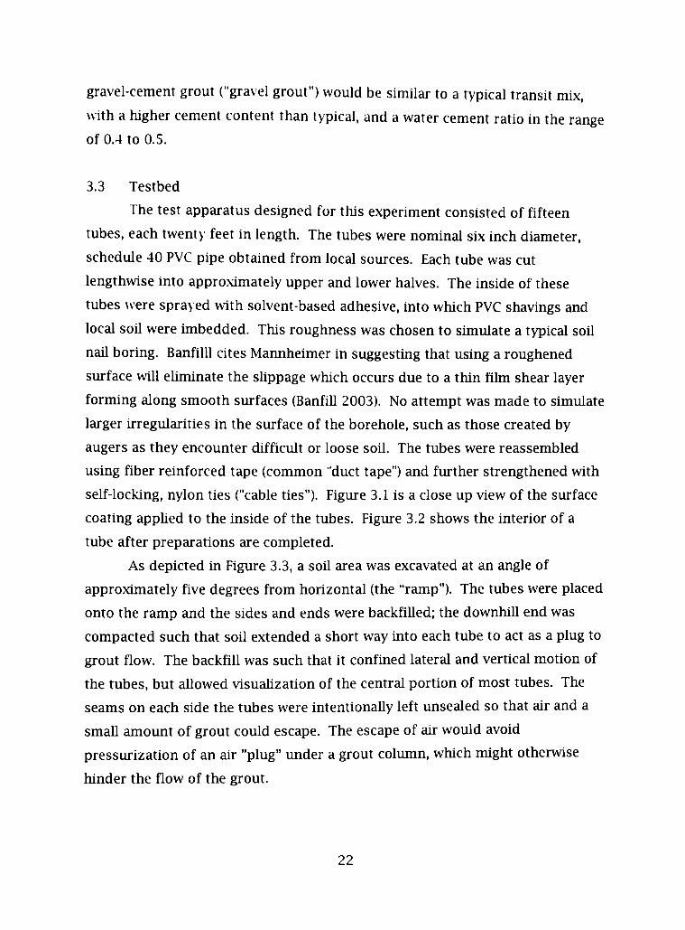
3.3 Testbed
The test apparatus designed for this experiment consisted of fifteen
tubes, each twenty feet in length. The tubes were nominal six inch diameter,
schedule 40 PVC pipe obtained from local sources. Each tube was cut
lengthwise into approximately upper and lower halves. The inside of these
tubes were sprayed with solvent-based adhesive, into which PVC shavings and
local soU were imbedded. This roughness was chosen to simulate a typical soU
naU boring. BanfilU cites Mannheimer in suggesting that using a roughened
surface wiU ehminate the slippage which occurs due to a thin film shear layer
forming along smooth surfaces (BanfiU 2003). No attempt was made to simulate
larger irregularities in the surface of the borehole, such as those created by
augers as they encounter difficult or loose soil. The tubes were reassembled
using fiber reinforced tape (common "duct tape") and further strengthened with
self-locking, nylon ties ("cable ties"). Figure 3.1 is a close up view of the surface
coating apphed to the inside of the tubes. Figure 3.2 shows the interior of a
tube after preparations are completed.
As depicted in Figure 3.3, a soil area was excavated at an angle of
approximately five degrees from horizontal (the "ramp"). The tubes were placed
onto the ramp and the sides and ends were backfiUed; the downhiU end was
compacted such that soil extended a short way into each tube to act as a plug to
grout flow. The backfiU was such that it confmed lateral and vertical mofion of
the tubes, but aUowed visualization of the central portion of most tubes. The
seams on each side the tubes were intentionaUy left unsealed so that air and a
smaU amount of grout could escape. The escape of air would avoid
pressurizafion of an ah "plug" under a grout column, which might otherwise
hinder the flow of the grout.
22
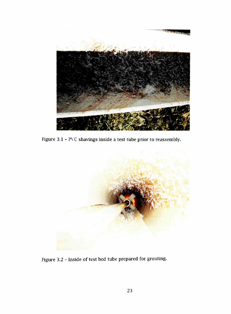
Figure 3.1 - P\ C shavings inside a test tube prior to reassembly.
Figure 3.2 - Inside of test bed tube prepared for grouting.
23
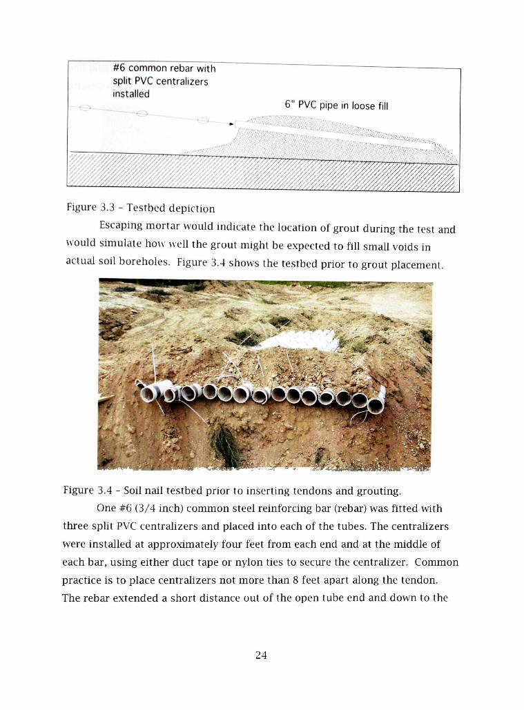
#6 common rebar with split PVC centralizers installed
6" PVC pipe in loose fill
" " ^ T ^ ' ^ ^ ' ^ ^ ? ^ ^
Figure 3.3 - Testbed depiction
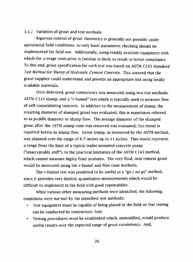
Escaping mortar would indicate the location of grout during the test and
would simulate how weU the grout might be expected to fiU smaU voids in
actual sou boreholes. Figure 3.4 shows the testbed prior to grout placement.
Figure 3.4 - Soil nail testbed prior to inserting tendons and grouting.
One #6 (3/4 inch) common steel reinforcing bar (rebar) was fitted with
three spht PVC centralizers and placed into each of the tubes. The centrahzers
were installed at approximately four feet from each end and at the middle of
each bar, using either duct tape or nylon ties to secure the centrahzer. Common
practice is to place centrahzers not more than 8 feet apart along the tendon.
The rebar extended a short distance out of the open tube end and down to the
24

soil plug in the distant end. Figure 3.5 shows common rebars whh centrahzers
attached and read> to be inserted into the testbed.
Figure 3.5 - Common #6 rebar with centrahzers
3.4 Experimental Parameters and Grout Placement
3.4.1 \ ariation of tremie
Three representative tremie insertion depths were selected: full depth
(about 19 feet), half depth (at approximately the middle centrahzer), and
minimal depth (near the first centrahzer.)
The full tremie tests were to determine if stiff grouts would consolidate
weU w hen tremied properly. It was postulated that under a full head (on this
test, about 24 inches) the stiff grout would consohdate weU. Upon completion
of the tests, examination of the length of the test grout columns should reveal
whether adequate consohdation and encapsulation has occurred.
The partial tremie lengths were selected to test the hypothesis that grout
tends to plug at centralizers, but wiU flow downhole where it has sufficient
pressure head and/or is sufficiently fluid. By placing the tremie a short distance
mto the tube on the minimal tremie cases, it could be observed whether grout
tended to flow under minimal head, and whether plugging occurred at the
centrahzers or elsewhere. The middle position tremie tests, when compared
with the minimal tremie tests, would indicate whether additional head increased
downhole grout flow.
25
3.4.2 Variation of grout and test methods
Rigorous control of grout rheometry is generally not possible under
operational field conditions, so only basic parametric checking should be
implemented for field use. AdditionaUy, using readUy available equipment with
which the a\ erage contractor is famUiar is likely to result in better comphance.
To this end, grout specification for each test was based on ASTM CHS Standard
Test Method for Slump of Hydraulic Cement Concrete. This assured that the
grout suppher could understand and provide an appropriate mix using locally
avaUable materials.
Once delivered, grout consistency was measured using two test methods:
ASTM C143 slump, and a "v-funnel" test which is typically used to measure flow
of self-consohdating concrete. In addition to the measurement of slump, the
resulting diameter of slumped grout was evaluated; this is sometimes referred
to as puddle diameter or slump flow. The average diameter of the slumped
grout after the ASTM slump cone was removed was evaluated; this result is
reported herein as slump flow. Grout slump, as measured by the ASTM method,
was planned over the range of 6-7 inches up to 11 inches. This would represent
a range from the hmit of a typical traUer mounted concrete pump
("unacceptably stiff"), to the practical hmitation of the ASTM CI43 method,
which caimot measure highly fluid mixtures. The very fluid, neat cement grout
would be measured using the v-furmel and flow cone methods.
The v-furmel test was predicted to be useful as a "go / no go" method,
since it provides very hmited, quantitative measurements which would be
difficult to hnplement in the field with good repeatabUity.
While various other measuring methods were identified, the foUowing
conditions were not met by the identified test methods:
• Test equipment must be capable of being placed in the field so that testing
can be conducted by contractors. And,
• Testing procedures must be estabhshed which, unmodified, would produce
useful results over the expected range of grout consistency. And,
26
• The test must not require precise measurements or timing, or other
procedures which are unlikely to be accepted or provide useable resuUs.
While various rheological testing equipment may be avaUable in the
future, practical field instruments are not readily avaUable for most
cementitious materials containing aggregate. The limit here appears to be the
ratio of equipment size to maximum aggregate size. (BanfiU 2003)
Grout constituents were selected to represent the likely materials
provided by a typical concrete suppher, and were chosen based on a local
suppher experience database; grout design variation and testing would allow
refinement of the grouts prior to use in an actual installation. Locally-available
material and limitations of the pumping equipment dictated the grout designs.
Fi\e grouts were selected: neat cement, sand-cement low slump ("Sand 1"), sand-
cement high slump ("Sand 2"), pea gravel low slump ("Gravel 1") and pea gravel
high slump ("Gravel 2"). Table 3.1 shows the grout constituents.
3.5 Testbed Installation
On the day of the test, weather was clear and mostly sunny.
Temperatures were in the 80's, with low humidity. The tubes were inspected for
debris and were found to be unobstructed and ready for grout. Grout
placement began shortly after noon, finishing about four hours after starting.
Samples of each grout mix were placed into plastic, 4 inch by 8 inch, cyhndrical
sample containers.
The sand cement grout was initially provided by the transit mix suppher
at an ASTM C143 slump of 8 inches. This material was installed into three
tubes, one at each tremie poshion. The same mixture was re-tempered with the
addition of water to the mix truck; ASTM slump was measured to be 11 inches.
The next set of four tubes was fUled with this grout using the three tremie
positions. In each case, the grout was pumped as the tremie was withdrawn,;
this was continued untU the end of the tremie was at the end of the tube and
the grout flowed from the open end. This was the process used in all cases.
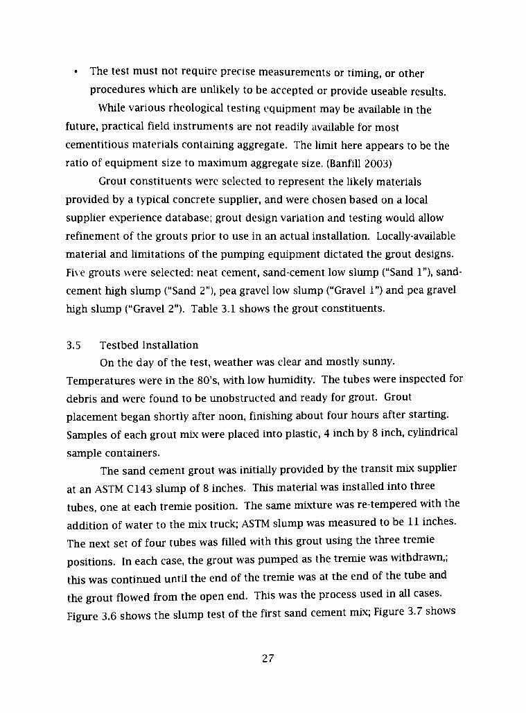
Figure 3.6 shows the slump test of the first sand cement mix; Figure 3.7 shows
27
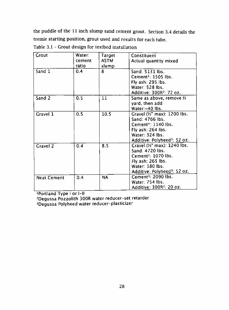
the puddle of the 11 inch slump sand cement grout. Section 3.4 details the
tremie starting position, grout used and results for each tube.
Table 3.1 - Grout design for testbed installation
Grout
Sand 1
Sand 2
Gravel 1
Crave! 2
Neat Cement
Water: cement ratio 0.4
0.5
0.5
0.4
0.4
Target ASTM slump 8
11
10.5
8.5
NA
Constituent Actual quantity mixed
Sand: 5131 lbs. Cementi: 1505 lbs. Fly ash: 295 lbs. Water: 528 lbs. Additive: SOOR :̂ 72 oz. Same as above, remove Vi yard, then add Water:~40 lbs. Gravel VA" max): 1200 lbs. Sand: 4766 lbs. Cement*: 1140 lbs. Fly ash: 264 lbs. Water: 324 lbs. Additive: Polyheed^: 52 oz. Gravel {'A" max): 1240 lbs. Sand: 4720 lbs. Cement^: 1070 lbs. Fly ash: 265 lbs. Water: 180 lbs. Additive: Polyheed^: 52 oz. Cementi: 2090 lbs. Water: 754 lbs. Additive: SOOR :̂ 20 oz.
^Portland Type I or l-ll ^Degussa Pozzolith 300R water reducer-set retarder ^Degussa Polyheed water reducer-plasticizer
28
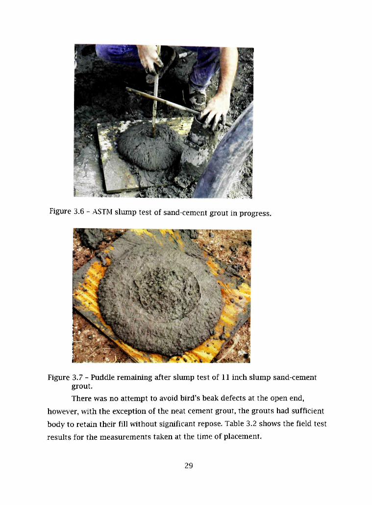
Figure 3.6 - ASTM slump test of sand-cement grout in progress.
Figure 3.7 - Puddle remaining after slump test of 11 inch slump sand-cement grout.
There was no attempt to avoid bird's beak defects at the open end,
however, with the exception of the neat cement grout, the grouts had sufficient
body to retain their fill without significant repose. Table 3.2 shows the field test
results for the measurements taken at the time of placement.
29

Table 3.2 - Grout Field Test Results
Grout
Sand 1
Sand 2
Gravel 1
Gravel 2
Neat Cement
Slump (inch)
8
11
10.5
8.5
NA
V-funnel (sec)
No flow
~2
~4
No flow
-2.5
Notes
Slump flow: 20 inches
Slump flow: 16 inches
Vi inch flow cone plugged by unmixed material and gravel
The pea gravel grout arrived at a slump of 10-1/2 inches, and was placed
into three tubes using the three tremie positions. A second batch was rejected
at the site as it arrived at greater than 10 inch slump. The final batch of gravel
grout tested at a slump of 8-1/2 inches; this was placed into the two remaining
tubes using full tremie and minimal tremie orUy. The transit ticket from the
suppher showed that an inferior grade of gravel was used for these gravel
mixes. It w as decided to go ahead with the tests in spite of the risk that this
grout would have compressive strength below the required 3000 psi at seven
days. This decision would not compromise the column-filling aspects of the
tests, but the mix design would not be suitable for actual soil nail installations.
Figure 3.8 is a view of the cross section of grout samples taken for
strength testing. The samples were prepared by crosscutting with a wet saw to
msure that the end surfaces were flat and perpendicular to the long axis.
Figure 3.8 - Cut section of grout samples showing gravel grout (left) and sand grout (right).
30
The final experiment used a mid-range water cement ratio for the neat
cement grout, w hich yielded a \ er> fluid grout with relatively low shrinkage.
The water-cement ratio was 0.37, and the grout was sUghtly viscous, yet very
fluid. This grout w as placed into three tubes. The first of these was placed
using full tremie; the second was placed using a minimal tremie. The tendon
was removed from the third tube, the grout was placed using a full length
tremie, then the tendon w ith the centralizers installed was inserted into the
grouted tube. Only minimal resistance was experienced when inserting the
tendon in this manner.
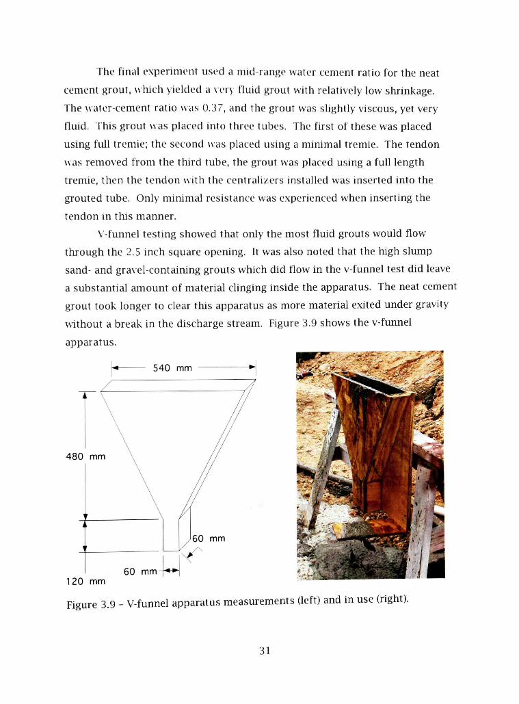
V-funnel testing showed that oiUy the most fluid grouts would flow
through the 2.5 inch square opening. It was also noted that the high slump
sand- and gravel-containing grouts which did flow in the v-funnel test did leave
a substantial amount of material clinging inside the apparatus. The neat cement
grout took longer to clear this apparatus as more material exited under gravity
without a break in the discharge stream. Figure 3.9 shows the v-funnel
apparatus.
480 mm
120 mm
Figure 3.9 - V-funnel apparatus measurements (left) and in use (right).
31
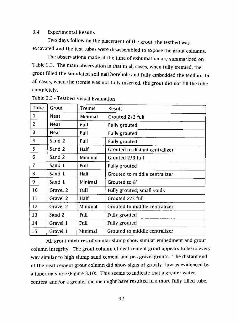
3.4 Experimental Results
Two days following the placement of the grout, the testbed was
e.xcavated and the test tubes were disassembled to expose the grout columns.
The observations made at the time of exhumation are summarized on
Table 3.3. The main observation is that in all cases, when fully tremied, the
grout fiUed the simulated soil nail borehole and fuUy embedded the tendon. In
all cases, when the tremie was not fully inserted, the grout did not fiU the tube
completely.
Table 3.3 - Testbed Visual Evaluation
Tube
1
2
3
4
5
6
7
8
9
10
11
12
13
14
15
Grout
Neat
Neat
Neat
Sand 2
Sand 2
Sand 2
Sand 1
Sand 1
Sand 1
Gravel 2
Gravel 2
Gravel 2
Sand 2
Gravel 1
Gravel 1
Tremie
Minimal
Full
Full
Full
Half
Minimal
Full
Half
Minimal
Full
Half
Minimal
Full
Full
Minimal
Result
Grouted 2/3 full
Fully grouted
Fully grouted
Fully grouted
Grouted to distant centralizer
Grouted 2/3 full
Fully grouted
Grouted to middle centralizer
Grouted to 8'
Fully grouted; small voids
Grouted 2/3 fuU
Grouted to middle centrahzer
Fully grouted
Fully grouted
Grouted to middle centralizer
All grout mixtures of similar slump show simUar embedment and grout
column integrity. The grout column of neat cement grout appears to be in every
way simUar to high slump sand cement and pea gravel grouts. The distant end
of the neat cement grout column did show signs of gravity flow as evidenced by
a tapering slope (Figure 3.10). This seems to indicate that a greater water
content and/or a greater inchne might have resulted in a more fully fiUed tube.
32
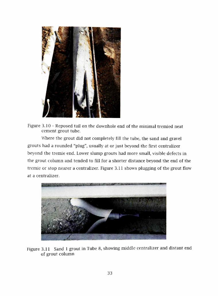
Figure 3.10 - Reposed tail on the downhole end of the minimal tremied neat cement grout tube.
\Vhere the grout did not completely fiU the tube, the sand and gravel
grouts had a rounded "plug", usually at or just beyond the first centrahzer
beyond the tremie end. Lower slump grouts had more small, visible defects in
the grout column and tended to fill for a shorter distance beyond the end of the
tremie or stop nearer a centralizer. Figure 3.11 shows plugging of the grout flow
at a centrahzer.
Figure 3.11 Sand 1 grout in Tube 8, showing middle centrahzer and distant end of grout column
33

Several t> pes of defects were noted as the tubes were exhumed. Figures
3.12 shows an air pocket defect m a neat cement column and Figures 3.13 and
3.14 show cylindrical \'oids. Each of these was apparently caused when the
tremie was withdrawn quicker than the tube filled with grout, thereby trapping
air and leaxing a defect.
Figure 3.12 - Neat grout in Tube 1, showing a void across about V2 of the grout column diameter.
34

Figure 3.13 - Sand grout column with a defect caused by withdrawal of the tremie from the surface of the grout as it was being pumped.
Figure 3.14 - Sand grout column with a defect caused as an air packet was formed during grouting.
35
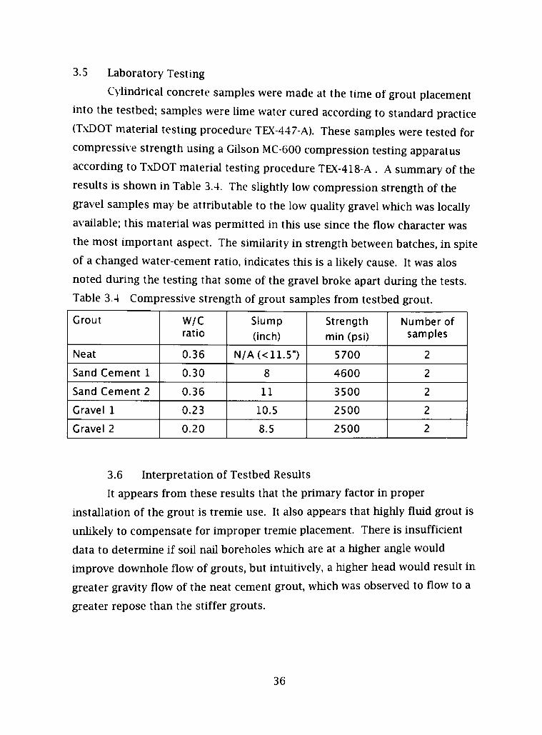
3.5 Laboratory Testing
Cylindrical concrete samples were made at the time of grout placement
into the testbed; samples were hme water cured according to standard practice
(TxDOT material testing procedure TEX-447-A). These samples were tested for
compressive strength using a GUson MC-600 compression testing apparatus
according to TxDOT material testing procedure TEX-418-A . A summary of the
results is shown in Table 3.4. The slightly low compression strength of the
gravel samples may be attributable to the low quality gravel which was locally
available; this material was permitted in this use since the flow character was
the most important aspect. The simUarity in strength between batches, in sphe
of a changed water-cement ratio, indicates this is a likely cause. It was alos
noted during the testing that some of the gravel broke apart during the tests.
Table 3.4 Compressive strength of grout samples from testbed grout.
Grout
Neat
Sand Cement 1
Sand Cement 2
Gravel 1
Gravel 2
W/C ratio
0.36
0.30
0.36
0.23
0.20
Slump
(inch)
N/A(<11.5")
8
11
10.5
8.5
Strength
min (psi)
5700
4600
3500
2500
2500
Number of samples
2
2
2
2
2
3.6 Interpretation of Testbed Results
It appears from these results that the primary factor in proper
mstallation of the grout is tremie use. It also appears that highly fluid grout is
unhkely to compensate for hnproper tremie placement. There is insufficient
data to determine if soU naU boreholes which are at a higher angle would
hnprove downhole flow of grouts, but intuitively, a higher head would result in
greater gravity flow of the neat cement grout, which was observed to flow to a
greater repose than the stiffer grouts.
36

Based on these observations, it appears that improperly tremied grout of
any type will not fiU a soil naU borings under typical, low angle, installation
conditions. It was also observed that proper tremie use is critical to successful
grouting of soU naUs, and that stiff (high slump) grouts wUl instaU with
acceptable filhng and consohdation when placed through a full length tremie.
37

CHAPTER 4
FULL SCALE FIELD TEST
Simultaneous to the testbed experiment, a full scale test wall was
developed w hich allowed vahdation of the testbed and extended available data
by implementing slightly different parameters. The grout mixtures used on this
test were simUar to the neat cement and sand-cement grouts designed for the
testbed experiment and equivalent pumps and tremies were used for both. The
site was prepared and soU nail installation was completed by a contractor
normally engaged in soU nail instaUation in the State of Texas.
4.1 Preparation and Installation
The test site was an undisturbed, native soU slope adjacent to a one acre
draw with overaU depth of about 20 feet. A bench was cut exposing
approximately seven vertical feet of cohesive, sandy-clay soU. The soil mass
appeared fairly uniform aside from some areas of cementation (in the form of
caliche). It was determined that the face of the wall would be stable enough to
stand for the test period without additional support and with minimal
deformation or spalUng.
Twenty-four driUed soU nails ranging in length from 5 to 25 feet in length
were installed at a 10 degree downward inchne from horizontal. The bores were
sbc inches in diameter and approximately 4 feet longer than the soU nail tendon
length, to allow fuU embedment of the tendons. The tendons were grade 60, #6,
Dywidag Threadbar which were fitted with spht PVC centralizers. The tendons
were placed into the borings and grouted using a 12 foot long, 1-1/2 inch
diameter PVC pipe tremie connected directly to the output hose on a traUer-
mounted Schwing concrete pump.
The grout placed for these tests was neat Portland cement at a water-
cement ratio of 0.37 for naUs 2 and 5, and sand cement grout with a slump of
11 inches for nails 1, 3 and 4. Tendons for these soU nails were 25 feet in
38

length. The other naUs in this wall received these same grouts, but are not
discussed further in this thesis. Grout was pumped and the tremie was
withdrawn as the borehole filled. The outside end of the grout column was
formed to pro\ ide a surface perpendicular to the soU naU; for this reason, the
ends of the grout columns were not visible after they were fiUed with grout untU
the forms were remo\ed se\oral days later.
The installation w as allowed to cure for 30 days. Grout samples were
tested at 7 days and all samples exceeded the 3000 psi minimum (to meet TX
DOT specifications). Figure 4.1 shows the field site after excavation and soU nail
installation.
4.
jF Jr
^—mr-r " l * ^ * * :??^.J'58WIF
.1-
Figure 4.1 - SoU nail test waU with nails instaUed.
4.2 Inspection
Prior to exhumation, the ends of the nails were inspected. All of the neat
cement grouted nails exhibited some degree of subsidence. As shown in Figures
4.2, the subsidence extends some way into the bore, and would have been
visible at the tune of grouting had the ends not been covered by a form
designed to give a flat front face to the naUs. The void seen in Figure 4.2 is
typical of ah of the neat cement grout soU nails on this waU. The void
documented in these photos was found to have resulted from incomplete filhng
of the bores as air was trapped below the grout due to the short tremie. It
39

appears that the grout then flowed into the space at the low end of the
borehole, creating the void seen in these figures. There may have been
additional volume loss due to shrinkage of the grout and absorption of water by
the surrounding dr> soil. One additional soU naU, elsewhere in the wall, made
with sand cement grout, shows a void open to the end, but it appears to have
resulted from a birds beak defect which formed at the mouth of the borehole in
spite of the formwork intended to prevent such defects.
Non-destructi\ e testing (NDT) was conducted on these soU nails, with the
result that the sand-cement grouted naUs appeared to be approximately 15 feet
long, rather than the planned depth of 25-29 feet. The NDT methods are
experimental on this type of installation, so the decision was made to exhume
certain nails, measure them, visualize the grout, and correlate NDT finding to in
situ conditions. The NDT methods used were based on how sound travels
through the grout material, and are stiU in development. The NDT testing also
showed that the neat cement grout extended to about 30 feet in length; the
exhumed neat cement naUs were about 30 feet long.
Figure 4.2 - Soil nail subsidence: Completed soU nail with subsidence of grout (left). Looking down the soU nail borehole into the void which did not remain fiUed with grout (right).
40
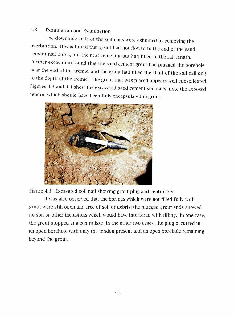
4.3 Exhumation and Examination
The do^vnhole ends of the soil nails were exhumed by removing the
overburden. It Nvas found that grout had not flowed to the end of the sand
cement naU bores, but the neat cement grout had fiUed to the fuU length.
Further excax ation found that the sand cemem grout had plugged the borehole
near the end of the tremie, and the grout had fiUed the shaft of the soU naU only
to the depth of the tremie. The grout that was placed appears weU consohdated.
Figures 4.3 and 4.4 show the excavated sand-cement soU naUs, note the exposed
tendon w hich should have been fully encapsulated in grout.
• r v 'T^^' •'<^' ̂ 'f̂ v? -̂:-:'--0,̂
. / '
l i : ^ . ^ ' , . ' . 1 . >:<..• * -^v
Figure 4.3 Excavated soU nail showing grout plug and centralizer.
It was also observed that the borings which were not fiUed fully with
grout were stUl open and free of soil or debris; the plugged grout ends showed
no soil or other inclusions which would have interfered with filhng. In one case,
the grout stopped at a centralizer, in the other two cases, the plug occurred in
an open borehole with orUy the tendon present and an open borehole remaining
beyond the grout.
41
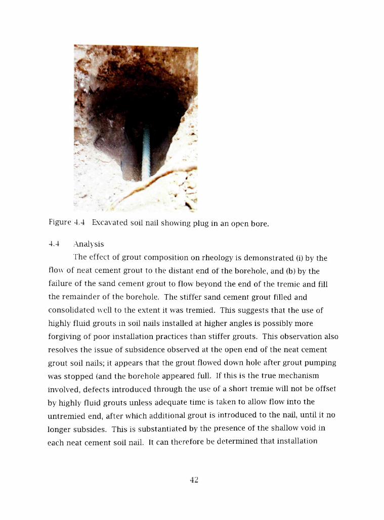
Figure 4.4 Excavated soU nail showing plug in an open bore.
4.4 .Analysis
The effect of grout composition on rheology is demonstrated (i) by the
flow of neat cement grout to the distant end of the borehole, and (b) by the
failure of the sand cement grout to flow beyond the end of the tremie and fill
the remainder of the borehole. The stiffer sand cement grout fiUed and
consohdated vveU to the extent it was tremied. This suggests that the use of
highly fluid grouts in soU nails instaUed at higher angles is possibly more
forgiving of poor instaUation practices than stiffer grouts. This observation also
resolves the issue of subsidence observed at the open end of the neat cement
grout soU naUs; it appears that the grout flowed down hole after grout pumping
was stopped (and the borehole appeared full. If this is the true mechanism
involved, defects introduced through the use of a short tremie wiU not be offset
by highly fluid grouts unless adequate time is taken to allow flow into the
untremied end, after which additional grout is introduced to the nail, untU it no
longer subsides. This is substanfiated by the presence of the shallow void in
each neat cement soU nail. It can therefore be determined that instaUafion
42

using a tremie significantly shorter than the borehole wUl likely resiUt in one or
more defects in the grout column, regardless of grout composition and fluidity.
The abiht> to maintain proper grouting in spite of improper instaUation
may make more fluid grouts desirable for some instaUations, however such
would not assure proper grout placement. Additionally, the use of stiffer grouts
should also be acceptable w hen installed properly. This result also reinforces
the testbed research finding that tremie insertion depth is the primary factor in
proper grout placement.
43

CHAPTER 5
DISCUSSION OF RESULTS AND RECOMMENDATIONS
From the observations made during e.xperimentation, several
generalizations can be made. These results can also be extrapolated to other
mix designs and extended to other parameters during design and instaUafion.
How ever, it must be recognized that variations in grout composition wiU affect
bond strength and withdrawal resistance, as weU as resistance to shear and
bending stresses w hich ma> affect a specific installation. It is generally
accepted that neat cement grout provides sufficient resistance to these stresses.
It is also accepted that the addition of smaU aggregates of sufficient quality
should not diminish the suitabUity of a grout, and may impart desirable
characteristics. Specific grout designs must be tested to assure that the design
requirements wiU be met. It may also be important to note that aggregates
added to a primarUy neat cement grout may impart toughness and assist in
controlhng crack size, both of which would be deshable in a soil nail where
corrosion protection and resistance to shear are necessary functions.
5.1 Effect of Tremie Insertion
The full-scale testbed results indicate that the single most important
factor in assuring proper grout placement is full insertion of the tremie pipe or
grout tube. This is verified in the actual soil nail instaUation examined here,
hiserfion of the tremie to fuU depth of the soil nail is required by FHWA and
TxDOT, and is standard practice in the industry, however adherence with this
reqiurement is not universal. It appears that any grout capable of being
pumped through general purpose concrete or grout pumps, wiU fiU the armular
space in the soU nail boring if properly placed through a full length tremie. It
was also observed that improperly placed grout of any type wiU not completely
fUl a soU naU boring under typical circumstances.
44

The field tests conducted herein indicate that gravity flow plays a much
greater role whore more fluid grouts are being installed into higher angle
boreholes. Howe\ er, there is insufficient evidence from these tests to determine
whether highly fluid grouts will completely fill higher angle (10-15 degree) soU
nail borings when pumped through short tremies. There does appear to be a
consistent finding of defects in soU naUs which are not tremied correctly,
without regard to grout type or flow character.
5.2 Grout Rheology
The use of highly fluid grouts, similar to those used in pre-placed
aggregate concrete or post-tensioning ducts, is common practice in soU nails
installation. The use of such grouts does not appear to correct for improper
installation techniques, nor is such highly fluid grout required to rehably create
good quahty soU naUs. It was noted that the voids observed in the low angle
test naUs with aU grouts, seemed to correspond to withdrawal of the tremie
whUe grout was not flowing (between pump strokes) or where the grout tube
was withdrawn faster than the borehole fUled.
In actual installations, with highly fluid, neat cement grout placed into
higher angle bores, the driUed soil nail cavity wiU likely fiU in spite of poor
placement practices. The gravity flow of grout beyond the tremie length may
take some tune to occur even with highly fluid grouts. Where full tremie is
used, a highly fluid grout may make the instaUation less difflcult and may be
more forgiving of various placement errors. However, with stiffer grouts, the
formation of defects at the open end of the borehole are more easily controlled;
with highly fluid grouts, there is no effective way to prevent a "bird's beak"
defect from forming.
5.3 Grout Composition
It appears that grouts of simUar slump wiU fill soU nail borings equaUty
weU. The presence or absence of aggregates up to 1/2 inch does not seem to
affect consohdation to any significant degree. The use of highly fluid grouts
45

with or without aggregates should be generally acceptable unless testing shows
that excessix e crack development due to shrinkage wiU reduce corrosion
protection. The use of stiffer grouts also appears to be suitable so long as good
installation technique is followed. Visual examination of grout removed from
samples show s no significant voids and shows continuous contact between the
grout and tendon. It appears that grout composition has httle effect on grout-
tendon embedment. There are considerations not made herein, such as those
affecting corrosion protection and strength of grout bond with the tendon. This
thesis includes only visual assessment of consohdafion and embedment of the
bar in exhumed nails and testbed samples. Grout composition may affect the
final strength and durabihty of the soil nail, and is the basis for the typical use
of compressi\ e strength as the primary specification of grout quahty.
5.4 Conclusions
The use of any grout with proper strength, which can be rehably pumped
using a tremie of the size and length necessary to reach the end of the soU nail,
should be acceptable. Higher slump mixes appear to provide more rehable
consohdation into the soil and around the tendon; this would be simUar to
concrete instaUation which is not vibrated during placement.
Tremie placement is the primary factor affecting proper grouting of the
soU naU. Stiff grouts wiU completely fill the boring if placed correctly with the
tremie extending the fuU design length of the soU nail. It is also demonstrated
that progressive removal of the grout pipe is acceptable where grout is pumped
continuously as the tremie is withdrawn, with the tremie end constantly stays
submerged within the grout column.
Angle of the soU naU boring is demonstrated to affect the flow of highly
fluid grouts to a greater extent than for stiffer grouts. Where a fuU length grout
pipe is unpractical, although highly fluid neat cement grouts may produce
acceptable results in soil naUs placed at a angle of 10 degrees or higher, the
completeness of grouting cannot be assured and this practice should be
46

avoided. Acceptable results can be assured by low pressure pumping only
through a full length tremie.
The current practice by some agencies, of requiring highly fluid, neat
cement grout has been shown to be unnecessary when grout is placed using
proper techniques. Measurement of grout consistency is therefore adequately
measured using .ASTM slump cone methods, and grouts as stiff as 8 to SVi inch
slump should be appropriate for typical soU nail instaUations. It is
recommended that neat cement grouts be hmited to a water-cement ratio
between 0.35 and 0.50, unless testing shows that other ratios will rehably
provide sufficient strength and not have excessive shrinkage.
5.5 Suggested Specifications
Below is a listing of suggested specification points for the installation of
soU nails. They should be modified to fh a particular specification, regional
avaUabihty of materials, and soU conditions:
1. Grout shall be neat cement grout, sand-cement grout or gravel-sand-
cement grout [#2 (1/2 inch) or smaUer aggregate, which attains a 7 day
compressive test strength of 3000 psi.
(NOTE: This strength is generally accepted as the minimum compressive
strength for soil naU grout; the specifying agency should evaluate the
suitabUity of this grout strength for each design.)
2. Acceptable sand-cement and gravel-sand-cement grout shall be no stiffer
than an ASTM slump of 8 'A inches. Water to cement ratio of a neat
cement grout shaU not be greater than 0.50.
3. Grout shall be placed using a grout pipe or tremie which is placed into the
sou naU borehole and extends to the fuU design depth of the soU naU. The
tremie or grout pipe shaU remain in the borehole while grout is pumped.
The tremie may be progressively removed from the borehole as the
borehole fUls with grout, such that the end of the tremie be kept
submerged in the grout being delivered.
47
4. Grouting of the entire soU nail shall be completed in one operation. Cold
joints which have been open for more than one hour shaU not be permitted
in the grout column.
5. Soil nails installed using highly fluid grouts, or installed into soU which is
prone to subsidence w hen e.xposed to moisture, shah be monitored during
the period immediately foUowing grout installation. If air pockets, gaps or
other signs of subsidence are found, additional grout shaU be placed so as
to fill the \oids.
6. During grout placement, the total amount of grout pumped shall be
monitored to assure that each soU nail has been fiUed with the correct
\ olume of grout.
7. Methods shall be used to prevent the bird's beak defect at the upper end of
the borehole from leaving the tendon exposed inside the borehole of the
completed soU nail.
[NOTE: It is widely accepted that the "bud's beak" is a normal condition,
and the unfUled space is generally fiUed with shotcrete or cast in place
concrete during the next steps of soU nail wall construction. The intent of
this requirement is: (a) to reduce the hkehhood of damage to the corrosion-
resistant coating on the tendon, and (b) to prevent having the tendon
imbedded through a cold joint, which could create a focal point for
corrosion in the completed soU nail waU.]
48
REFERENCES
. \C7 318-02 Building Code Requirements for Structural Concrete and Commentary (2002) American Concrete Institute.
.ASTM C143 Standard Test Method for Slump of Hydraulic Cement Concrete (2003), ASTM International (formerly American Society for Testing and Materials).
.ASTM C939 Standard Test Method for Flow of Grout for Preplaced-Aggregate Concrete (Flow Cone Method) (2002), ASTM International (formerly American Society for Testing and Materials).
Banerjee, S., Andrew Finney, Todd Wentworth, and Mahahngam Bahiradhan (1998) Evaluation of Design Methodologies For Soil Nailed Walls, Volume 1; Evaluation of Design Methodologies For Soil Nailed Walls, Volume 2: Distribution of Axial Forces in Soil Nails Based on Interpretation of Measured Strains; Evaluation of Design Methodologies for Soil Nailed Walls. Volume 3: .An Evaluation of Soil Nailing Analysis Packages, Department of Ci\11 Engineering, University of Washington, Seattle, Washington.
BanfUl, P. F. G., "The Rheology of Fresh Cement and Concrete - A Review", Proceedings of the IT" International Cement Chemistry Congress, Durban, May 2003.
ByTne, R.J., Cotton, D., Porterfield, J., Wolschlag, C, and Ueblacker, G., FHWA-DP-96-69R Manual for Design and Construction Monitoring of Soil Nail Walls, Report (1998), Federal Highway Administration, Washington, D.C.
Byrne, J.R., Ronald G. Chassie, James W. Keeley, Donald A. Bruce, Peter Nicholson, John L. Walkinshaw, Al DiMilho, Ken A. Jackura, Ron Chapman, and Claus Ludwig (1993), FHWA Tour for Geotechnology - Soil Nailing, Federal Highway Administration, Washington D.C, FHWA-PL-93-020.
French National Research Project CLOUTERRE (1993) Recommendations CLOUTERRE 1991 Presses de I'Ecole Nafionale des Ponts et Claussees" Enghsh Translation: French National Research Project Clouterre, 1991-Recommendations Clouterre 1991, Soil Nailing Recommendations, Pubhcation FHWA-SA-93-026, (1993) Federal Highway Administrafion, Washington, D.C. (Referenced as CLOUTERRE 1993)
49

Colder Associates Inc. (1998), Synthesis Report on Soil Nail Wall Facing Design.
Jin, J. (2002), Properties of mortar for self-compacting concrete, PfjD Thesis, University of London, pp.398.
Lazarte, Carlos A., Ph.D., P.E, Victor Ehas, P.E, R. David Espinoza,Ph.D., P.E, Paul J. Sabatini, Ph.D., P.E., GeoSyntec Consultants (March 2003) FHWAO-IF-03-017 Geotechnical Engineering Circular No. 7: Soil Nail Walls, US DOT Federal Highway Administration, Washington, DC.
Mannheimer, R.J. (1983), Effect of shp on flow properties of cement slurries can flaw resistance calculations, 0/7 and Gas Journal December 5, pp.144-147.
Porterfield, J.A., Cotton, D.M., Byrne, R.J., Wolschlag, C, and Ueblacker, G., (1998) Manual for Design and Construction Monitoring of Soil Nail Walls, Federal Highway .Administration, Washington D.C, FHWA-SA-96-069R.
Porterfield, J..A., Cotton, D.M., Byrne, R.J., (1994) Soil Nailing Inspectors Manual Federal Highway Administration, Washington D.C, FHWA-SA-93-068.
Sakr, C.T., and Robert Kimmerling, (1995) Soil Nailing of a Bridge Embankment (Interstate-5 Swift Delta Soil Nail Wall), Oregon Department of Transportation.
Singla, Sumant (December 1999), FHWA-IF-99-026: Demonstration Project 103: Design & Construction Monitoring of Soil Nail Walls, Project Summary Report, US DOT Federal Highway Administration, Washington, DC.
Texas Department of Transportafion (2004), TEX-437-A Test for Flow of Grout Mixtures (Flow Cone Method), TxDOT Manual of Testing Procedures.
Tufenkjian, Mark R., Mladen Vucetic, "Dynamic Failure Mechanism of SoU-Nailed Excavafion Models in Centrifuge", Journal of Geotechnical and Geoenvironmental Engineering - March 2000 - Volume 126, Issue 3, pp. 227-235
50

PERMISSION TO COPY
In presenting this thesis in partial fulfillment of the requirements for a master's
degree at Texas Tech University or Texas Tech University Health Sciences Center, I
agree that the Library and my major department shall make it freely available for
research purposes. Permission to copy this thesis for scholarly purposes may be
granted by the Director of the Library or my major professor. It is understood that any
copying or publication of this thesis for financial gain shall not be allowed without my
further written permission and that any user may be liable for copyright infringement.
Agree (Permission is granted.)
Smdent Signamre Date
Disagree (Permission is not granted.)
Student Signature Date