installation,user's,and maintenance guide · installation,user's,and maintenance guide...
TRANSCRIPT
IBM System Storage DS3500 and EXP3500 StorageSubsystem
Installation, User's, and MaintenanceGuide
GA32-0952-06
���
NoteBefore using this information and the product it supports, read the general information in “Notices” on page 191 and seethe Warranty Information document that comes with the storage subsystem.
This edition applies to the IBM System Storage DS3500 and EXP3500 Storage Subsystem with controller firmwareversion 7.70, and to all subsequent releases and modifications until otherwise indicated in new editions.
This edition replaces GA32-0952-05.
© Copyright IBM Corporation 2010, 2013.US Government Users Restricted Rights – Use, duplication or disclosure restricted by GSA ADP Schedule Contractwith IBM Corp.
Contents
Figures . . . . . . . . . . . . . . . v
Tables . . . . . . . . . . . . . . . vii
Safety . . . . . . . . . . . . . . . ixSafety statements . . . . . . . . . . . . . x
Chapter 1. Introduction . . . . . . . . 1What's new in this release . . . . . . . . . . 2DS3500 storage subsystem overview . . . . . . 2EXP3500 storage enclosure overview . . . . . . 3Notices and statements in this document . . . . . 4Features and operating specifications . . . . . . 4Models and optional devices . . . . . . . . . 6Operating-system support . . . . . . . . . . 7Product updates . . . . . . . . . . . . . 8Best practices guidelines . . . . . . . . . . 8DS3500 storage subsystem and EXP3500 storageenclosure components . . . . . . . . . . . 9
Disk drives and bezels. . . . . . . . . . 10Controllers . . . . . . . . . . . . . 12Environmental service modules. . . . . . . 13AC power supply and fan units . . . . . . 13DC power supply and fan units . . . . . . 14Battery units . . . . . . . . . . . . . 15
Software and hardware compatibility and upgrades 15Software and firmware support code upgrades 15Determining firmware levels . . . . . . . 17
Specifications . . . . . . . . . . . . . . 17Area requirements . . . . . . . . . . . 17Temperature and humidity . . . . . . . . 19Electrical requirements . . . . . . . . . 20Heat output, airflow, and cooling . . . . . . 22
Chapter 2. Installing the storagesubsystem and storage enclosure . . . 25Installing the DS3500 storage subsystem . . . . . 25
Inventory checklist . . . . . . . . . . . 25DS3500 installation overview . . . . . . . 26Handling static-sensitive devices . . . . . . 27Preparing for installation . . . . . . . . . 28Installing the DS3500 storage subsystem in a rack 29
Installing the EXP3500 storage enclosure. . . . . 29Inventory checklist . . . . . . . . . . . 29Installing the EXP3500 storage enclosure in a rack 30
Chapter 3. Cabling the storagesubsystem and storage enclosure . . . 31Cabling the DS3500 storage subsystem . . . . . 31
Controller connectors (with Fibre Channel hostport adapters) . . . . . . . . . . . . 31Controller connectors (with 1 Gbps iSCSI hostport adapters) . . . . . . . . . . . . 31
Controller connectors (with 10 Gbps iSCSI hostport adapters) . . . . . . . . . . . . 32Controller connectors (with SAS host portadapters) . . . . . . . . . . . . . . 33Enclosure ID settings . . . . . . . . . . 33Working with SAS cables . . . . . . . . . 33Working with SFP modules and fiber optic cables 35Cabling the EXP3500 storage enclosure . . . . 45Connecting storage enclosures to the DS3500 . . 48Upgrading a single-controller to a dual-controllerwhen there is no attached EXP3500 enclosure . . 55Upgrading a single-controller to a dual-controllerwhen there is one or more EXP3500 enclosuresattached to the storage subsystem . . . . . . 55Connecting secondary interface cables . . . . 55Configuring the storage subsystem . . . . . 56Overview of installing an IBM BladeCenterconfiguration to connect to a DS3500 . . . . . 75
Cabling the DS3500 and EXP3500 ac power supplies 77Cabling the DS3500 and EXP3500 dc power supplies 78
Chapter 4. Operating the storagesubsystem and storage enclosure . . . 81Performing the health check process . . . . . . 81Hardware inspection . . . . . . . . . . . 82Turning on the storage subsystem . . . . . . . 82Installing the Storage Manager Client. . . . . . 85Monitoring status through software . . . . . . 85
Firmware updates . . . . . . . . . . . 86Troubleshooting the storage subsystem . . . . 87
Checking the LEDs . . . . . . . . . . . . 88AC power-supply LEDs . . . . . . . . . 88DC power-supply LEDs . . . . . . . . . 88Front LEDs . . . . . . . . . . . . . 89Controller LEDs . . . . . . . . . . . . 90Seven-segment numeric display LEDs . . . . 93ESM LEDs. . . . . . . . . . . . . . 94
Turning off the storage subsystem . . . . . . . 95Performing an emergency shutdown . . . . . 98Restoring power after an unexpected shutdown 98
Recovering from an overheated power supply . . . 99Cache memory and cache battery. . . . . . . 101
Cache memory . . . . . . . . . . . . 101Controller cache battery . . . . . . . . . 102Cache battery learn cycle . . . . . . . . 102
Chapter 5. Replacing components . . 105OK to remove LED . . . . . . . . . . . 105Working with controllers . . . . . . . . . 105
Removing a controller . . . . . . . . . 106Removing and installing a cover . . . . . . 107Installing a controller . . . . . . . . . . 107Replacing a controller . . . . . . . . . 109Removing and disposing of the system-boardlithium battery . . . . . . . . . . . . 114
© Copyright IBM Corp. 2010, 2013 iii

Installing an optional host port adapter orreplacing a failed host port adapter . . . . . . 116Working with hot-swap drives . . . . . . . 121
Removing a hard disk drive . . . . . . . 122Installing a hard disk drive . . . . . . . . 124Replacing a hot-swap drive. . . . . . . . 126Replacing multiple drives . . . . . . . . 126
Replacing an ac power supply. . . . . . . . 132Replacing a dc power supply . . . . . . . . 137Replacing a power-fan controller in the DS3500controller-drive enclosure . . . . . . . . . 142Replacing a battery . . . . . . . . . . . 148Replacing the memory cache DIMM. . . . . . 150
Removing the DIMM . . . . . . . . . . 151Installing the DIMM . . . . . . . . . . 152Turning on the storage subsystem afterreplacing components . . . . . . . . . 153Replacing an SFP transceiver in the DS3500storage subsystem controller enclosureconfiguration . . . . . . . . . . . . 154
Replacing the bezels . . . . . . . . . . . 156Removing the bezels . . . . . . . . . . 156Installing the bezels . . . . . . . . . . 157
Working with environmental service modules . . 157Installing an additional ESM . . . . . . . 157Replacing an ESM . . . . . . . . . . . 158
Replacing a midplane assembly . . . . . . . 159
Chapter 6. Solving problems . . . . . 161Solving problems in the DS3500 storage subsystem 161Solving problems in the EXP3500 storage enclosure 167Seven-segment display sequence codes and theircauses . . . . . . . . . . . . . . . . 169
Chapter 7. Parts listing, DS3500storage subsystem and EXP3500storage enclosure . . . . . . . . . 175Replaceable components. . . . . . . . . . 175DS3512 storage subsystem and EXP3512 storageenclosure parts listing . . . . . . . . . . 175DS3524 storage subsystem and EXP3524 storageenclosure parts listing . . . . . . . . . . 177Power cords . . . . . . . . . . . . . . 179Determining basic information of drive FRUs . . 181
Appendix A. Records . . . . . . . . 183Identification numbers . . . . . . . . . . 183Hard disk drive locations . . . . . . . . . 183Storage subsystem and controller informationrecord . . . . . . . . . . . . . . . . 184
Appendix B. Getting help andtechnical assistance . . . . . . . . 187Before you call . . . . . . . . . . . . . 187Using the documentation . . . . . . . . . 188Getting help and information from the World WideWeb . . . . . . . . . . . . . . . . 188Software service and support . . . . . . . . 188Hardware service and support . . . . . . . 188Taiwan contact information. . . . . . . . . 189
Notices . . . . . . . . . . . . . . 191Trademarks . . . . . . . . . . . . . . 192Important notes . . . . . . . . . . . . 193Particulate contamination . . . . . . . . . 193Documentation format . . . . . . . . . . 194Electronic emission notices . . . . . . . . . 194
Federal Communications Commission statement 194Industry Canada compliance statement . . . . 195Australia and New Zealand Class A Statement 195European Union Electromagnetic CompatibilityDirective . . . . . . . . . . . . . . 195Germany Electromagnetic compatibilitydirective . . . . . . . . . . . . . . 196Japan Voluntary Control Council for Interference(VCCI) Class A Statement . . . . . . . . 197Japan Electronics and Information TechnologyIndustries Association (JEITA) Statement (lessthan or equal to 20 A per phase) . . . . . . 197Korean Communications Commission (KCC)Class A Statement . . . . . . . . . . . 197Russia Electromagnetic Interference (EMI) ClassA Statement . . . . . . . . . . . . . 197People's Republic of China Class A ElectronicEmission statement . . . . . . . . . . 198Taiwan Class A compliance statement . . . . 198
Index . . . . . . . . . . . . . . . 199
iv IBM System Storage DS3500 and EXP3500 Storage Subsystem: Installation, User's, and Maintenance Guide
Figures
1. Serial number label, and product name,machine type, and model number labellocations . . . . . . . . . . . . . . 2
2. DS3512 storage subsystem and EXP3512storage enclosure hot-swap drive bays andbezels . . . . . . . . . . . . . . 10
3. DS3524 storage subsystem and EXP3524storage enclosure hot-swap drive bays andbezels . . . . . . . . . . . . . . 10
4. Left-side bezel. . . . . . . . . . . . 115. Right-side bezel (DS3512 and EXP3512) 116. Bottom shelf (DS3524 and EXP3524) . . . . 117. Rear view, single-controller model (shown
without an optional host port adapter) . . . 138. Rear view, single ESM model storage enclosure 139. AC power supply components . . . . . . 14
10. DC power supply components . . . . . . 1411. DC power supply connector - pin positions 1412. Battery unit . . . . . . . . . . . . 1513. DS3512 storage subsystem and EXP3512
storage enclosure dimensions . . . . . . 1814. DS3524 storage subsystem and EXP3524
storage enclosure dimensions . . . . . . 1815. Example of cold aisle/hot aisle rack
configuration . . . . . . . . . . . . 2316. Dual-controller DS3500 storage subsystem
ports and controllers (with optional FibreChannel host port adapter) . . . . . . . 31
17. Dual-controller DS3500 storage subsystemports and controllers (with optional iSCSI hostport adapter) . . . . . . . . . . . . 32
18. Dual-controller DS3500 storage subsystemports and controllers (with optional 10 iSCSIhost port adapter) . . . . . . . . . . 32
19. Dual-controller DS3500 storage subsystemports and controllers (with an optional SAShost port adapter) . . . . . . . . . . 33
20. Mini-SAS cable . . . . . . . . . . . 3421. Connecting a mini-SAS cable. . . . . . . 3422. Removing a mini-SAS cable . . . . . . . 3523. SFP module and protective cap . . . . . . 3824. Installing an SFP module into the host port 3825. Unlocking the SFP module latch - plastic
variety . . . . . . . . . . . . . . 3926. Unlocking the SFP module latch - wire variety 3927. LC-LC Fibre Channel cable . . . . . . . 4028. Removing fiber optic cable protective caps 4129. Inserting an LC-LC Fibre Channel cable into
an SFP module . . . . . . . . . . . 4130. LC-LC Fibre Channel cable lever and latches 4231. Removing the LC-LC Fibre Channel cable 4232. LC-SC Fibre Channel cable adapter . . . . 4333. Removing the LC-SC cable adapter protective
caps . . . . . . . . . . . . . . . 4434. Connecting an LC-LC cable into the LC-SC
cable adapter . . . . . . . . . . . . 44
35. LC-LC Fibre Channel cable lever and latches 4536. Removing the LC-LC Fibre Channel cable from
an LC-SC Fibre Channel cable adapter . . . 4537. ESM connectors . . . . . . . . . . . 4538. Example of a redundant drive path . . . . 5039. One single-controller DS3500 and multiple
single-ESM storage enclosures . . . . . . 5140. A dual-controller DS3500 and a storage
enclosure . . . . . . . . . . . . . 5241. A dual-controller DS3500 and two storage
enclosures . . . . . . . . . . . . . 5242. A dual-controller DS3500 and eight storage
enclosures . . . . . . . . . . . . . 5343. Ethernet port locations on a dual-controller
DS3500 . . . . . . . . . . . . . . 5644. Host-agent (in-band) managed storage
subsystems. . . . . . . . . . . . . 5745. Direct (out-of-band) managed storage
subsystems. . . . . . . . . . . . . 5846. Single-controller direct-attached SAS
connection to a single-host HBA . . . . . 6047. Single-controller direct-attached SAS
connection to dual HBAs in a single-host(redundant host connection) . . . . . . . 60
48. Single-controller direct-attached SASconnection to single HBAs in multiple hosts . 61
49. Dual-controller direct-attached SAS connectionto two HBAs in the same host (redundant hostconnection) . . . . . . . . . . . . 61
50. Dual-controller direct-attached SASconnections to multiple HBAs in multiplehosts . . . . . . . . . . . . . . . 62
51. Dual-controller DS3500 or single-controllerDS3500 SAS connection to multiple hosts usingone SAS switch . . . . . . . . . . . 62
52. Dual-controller DS3500 SAS connection tomultiple hosts using two separate SASswitches. . . . . . . . . . . . . . 63
53. Multiple dual-controller DS3500s SASconnection to multiple hosts using two usingtwo separate SAS switches . . . . . . . 63
54. Dual-controller DS3500 SAS connection tomultiple hosts using two SAS switches that areconnected together via an interlink switch . . 64
55. Location of host connectors on storagecontrollers . . . . . . . . . . . . . 65
56. Single-controller direct-attached Fibre Channelconnection to a single host HBA . . . . . 65
57. Single-controller direct-attached Fibre Channelconnection to dual HBAs (redundant hostconnection) . . . . . . . . . . . . 66
58. Single-controller direct-attached Fibre Channelconnection to single HBAs in multiple hosts . 67
59. Dual-controller direct-attached Fibre Channelconnection to two HBAs in the same host(redundant host connection) . . . . . . . 67
© Copyright IBM Corp. 2010, 2013 v

60. Dual-controller direct-attached Fibre Channelconnections to multiple HBAs in multiplehosts . . . . . . . . . . . . . . . 68
61. Example of a single Fibre Channel SAN fabricconfiguration . . . . . . . . . . . . 69
62. Example of a dual Fibre Channel SAN fabricconfiguration . . . . . . . . . . . . 69
63. Example of two storage subsystems in a dualFibre Channel SAN environment . . . . . 70
64. Single-host, single-controller iSCSIconfiguration . . . . . . . . . . . . 71
65. Multiple-port, single-controller iSCSIconfiguration . . . . . . . . . . . . 72
66. Multiple single-port hosts, single-controlleriSCSI configuration . . . . . . . . . . 72
67. Multiple-host, multiple-port, single-controller,and redundant-path iSCSI configuration . . . 73
68. Multiple-host, multiple-port,multiple-storage-subsystem iSCSI configuration 73
69. Single-host, multiple-port, dual-controlleriSCSI configuration . . . . . . . . . . 74
70. Multiple-host, multiple-port, dual-controlleriSCSI configuration . . . . . . . . . . 74
71. Example of a multiple-host, multiple-port, andmultiple-fabric (Fibre Channel or iSCSI, andSAS) configuration . . . . . . . . . . 75
72. Example of a DS3500 that is connected to aBladeCenter unit . . . . . . . . . . . 77
73. DC power connector - pin positions . . . . 7974. DC wiring from DS3500 to disconnect device
and dc power source . . . . . . . . . 7975. Power-supply switches and connectors for
DS3500 ac models . . . . . . . . . . 8476. Power-supply switches and connectors for
DS3500 dc models . . . . . . . . . . 8477. AC power-supply LEDs . . . . . . . . 8878. DC power-supply LEDs . . . . . . . . 8979. DS3512 storage subsystem and EXP3512
storage enclosure front LEDs and controls . . 8980. DS3524 storage subsystem and EXP3524
storage enclosure front LEDs. . . . . . . 9081. Controller LEDs . . . . . . . . . . . 9182. iSCSI host port adapter LEDs . . . . . . 9283. Fibre Channel host port adapter LEDs . . . 9284. SAS host port adapter LEDs . . . . . . . 9385. 10 Gbps iSCSI port LEDs . . . . . . . . 9386. Numeric display LEDs . . . . . . . . . 9487. ESM LEDs . . . . . . . . . . . . . 9588. Removing a controller . . . . . . . . 10689. Removing the cover . . . . . . . . . 107
90. Installing a controller . . . . . . . . . 10991. Removing and replacing a controller . . . . 11192. Removing the battery unit from the controller 11293. Cache backup flash memory device . . . . 11394. Sequence of removing controller components 11795. Removing a controller. . . . . . . . . 11896. Removing the host port adapter filler panel 11997. Installing a host port adapter . . . . . . 12098. DS3512 storage subsystem and EXP3512
storage enclosure drive LEDs . . . . . . 12299. DS3524 storage subsystem and EXP3524
storage enclosure drive LEDs . . . . . . 122100. Removing a drive from a DS3512 or EXP3512 123101. Removing a drive from a DS3524 or EXP3524 124102. Installing a drive in a DS3512 or EXP3512 125103. Installing a drive in a DS3524 or EXP3524 125104. Replacing a power supply . . . . . . . 136105. Replacing a power supply . . . . . . . 141106. AC power-supply LEDs . . . . . . . . 143107. Power-supply switches and connectors for
DS3500 AC models . . . . . . . . . 143108. Replacing a power supply . . . . . . . 144109. DC power-supply LEDs . . . . . . . . 145110. DC power connectors for DS3500 DC models 146111. Power-supply switches and connectors for
DS3500 dc models . . . . . . . . . . 146112. Replacing a power supply . . . . . . . 147113. Removing a controller . . . . . . . . 149114. Removing a battery unit from the controller 149115. Memory cache DIMM location . . . . . . 151116. Removing a controller . . . . . . . . 151117. Removing the DIMM from the controller 152118. Installing the DIMM in the controller 152119. DS3524 storage subsystem and EXP3524
storage enclosure front LEDs . . . . . . 153120. Controller LEDs. . . . . . . . . . . 155121. Installing an SFP module into the host port 155122. Removing the bezels . . . . . . . . . 156123. Removing an environmental service module 158124. Replacing the midplane assembly in a DS3512
or EXP3512 . . . . . . . . . . . . 159125. Replacing the midplane assembly in a DS3524
or EXP3524 . . . . . . . . . . . . 160126. Seven-segment alphanumeric characters 169127. DS3512 storage subsystem and EXP3512
storage enclosure storage subsystem parts . . 176128. DS3524 storage subsystem and EXP3524
storage enclosure parts . . . . . . . . 178129. An IBM hologram label example . . . . . 182130. Serial number location on the DS3500 183
vi IBM System Storage DS3500 and EXP3500 Storage Subsystem: Installation, User's, and Maintenance Guide
Tables
1. Features and operating specifications . . . . 52. DS3500 storage subsystem models and optional
devices . . . . . . . . . . . . . . 63. DC power supply connector - pin descriptions 154. DS3512 storage subsystem and EXP3512
storage enclosure weights . . . . . . . . 185. DS3524 storage subsystem and EXP3524
storage enclosure weights . . . . . . . . 196. DS3500 component weights . . . . . . . 197. Temperature and humidity requirements for
storage subsystems in an InformationTechnology (IT) or office environment. . . . 20
8. Temperature and humidity requirements forstorage subsystems in a NEBS/ETSI compliantenvironment . . . . . . . . . . . . 20
9. DS3500 ac power requirements . . . . . . 2110. DS3500 dc power requirements . . . . . . 2111. Maximum number of EXP3512 and EXP3524
storage enclosures with controller firmwarelevel 7.77.xx.xx and later . . . . . . . . 48
12. Maximum number of EXP3512 and EXP3524storage enclosures with controller firmwarelevel 7.75.xx.xx and earlier . . . . . . . 49
13. DC power supply connector - pin descriptions 79
14. DC power source wiring descriptions . . . . 8015. Fibre Channel port LEDs . . . . . . . . 9216. Troubleshooting. . . . . . . . . . . 16217. Troubleshooting information . . . . . . 16718. Seven-segment display sequence code
definitions . . . . . . . . . . . . 17019. Repeating sequences on the seven-segment
display and corresponding errors . . . . . 17120. Controller numeric display diagnostic codes 17221. ESM numeric display diagnostic codes 17322. Parts listing for the DS3512 storage subsystem
and EXP3512 storage enclosure storagesubsystem . . . . . . . . . . . . 176
23. Parts listing for the DS3524 storage subsystemand EXP3524 storage enclosure storagesubsystem . . . . . . . . . . . . 178
24. IBM power cords . . . . . . . . . . 18025. Product identification record . . . . . . 18326. Drive location information record . . . . . 18427. Storage subsystem and controller information
record . . . . . . . . . . . . . . 18428. Sample information record . . . . . . . 18529. Limits for particulates and gases . . . . . 194
© Copyright IBM Corp. 2010, 2013 vii

viii IBM System Storage DS3500 and EXP3500 Storage Subsystem: Installation, User's, and Maintenance Guide

Safety
Before installing this product, read the Safety Information.
Antes de instalar este produto, leia as Informações de Segurança.
Læs sikkerhedsforskrifterne, før du installerer dette produkt.
Lees voordat u dit product installeert eerst de veiligheidsvoorschriften.
Ennen kuin asennat tämän tuotteen, lue turvaohjeet kohdasta Safety Information.
Avant d'installer ce produit, lisez les consignes de sécurité.
Vor der Installation dieses Produkts die Sicherheitshinweise lesen.
Prima di installare questo prodotto, leggere le Informazioni sulla Sicurezza.
© Copyright IBM Corp. 2010, 2013 ix

Les sikkerhetsinformasjonen (Safety Information) før du installerer dette produktet.
Antes de instalar este produto, leia as Informações sobre Segurança.
Antes de instalar este producto, lea la información de seguridad.
Läs säkerhetsinformationen innan du installerar den här produkten.
Safety statementsThese statements provide the caution and danger information used in thisdocumentation.
Important:
Each caution and danger statement in this documentation is labeled with anumber. This number is used to cross reference an English-language caution ordanger statement with translated versions of the caution or danger statement inthe Safety Information document.
For example, if a caution statement is labeled “Statement 1,” translations for thatcaution statement are in the Safety Information document under “Statement 1.”
Be sure to read all caution and danger statements in this documentation before youperform the procedures. Read any additional safety information that comes withyour system or optional device before you install the device.
Statement 1
x IBM System Storage DS3500 and EXP3500 Storage Subsystem: Installation, User's, and Maintenance Guide

DANGER
Electrical current from power, telephone, and communication cables ishazardous.
To avoid a shock hazard:
v Do not connect or disconnect any cables or perform installation,maintenance, or reconfiguration of this product during an electrical storm.
v Connect all power cords to a properly wired and grounded electrical outlet.
v Connect to properly wired outlets any equipment that will be attached tothis product.
v When possible, use one hand only to connect or disconnect signal cables.
v Never turn on any equipment when there is evidence of fire, water, orstructural damage.
v Disconnect the attached power cords, telecommunications systems,networks, and modems before you open the device covers, unlessinstructed otherwise in the installation and configuration procedures.
v Connect and disconnect cables as described in the following table wheninstalling, moving, or opening covers on this product or attached devices.
To Connect: To Disconnect:
1. Turn everything OFF.
2. First, attach all cables to devices.
3. Attach signal cables to connectors.
4. Attach power cords to outlet.
5. Turn device ON.
1. Turn everything OFF.
2. First, remove power cords from outlet.
3. Remove signal cables from connectors.
4. Remove all cables from devices.
Statement 2
CAUTION:When replacing the lithium battery, use only IBM® Part Number 33F8354 or anequivalent type battery recommended by the manufacturer. If your system has amodule containing a lithium battery, replace it only with the same module typemade by the same manufacturer. The battery contains lithium and can explode ifnot properly used, handled, or disposed of.
Do not:
v Throw or immerse into water
v Heat to more than 100°C (212°F)
v Repair or disassemble
Dispose of the battery as required by local ordinances or regulations.
Safety xi

Statement 3
CAUTION:When laser products (such as CD-ROMs, DVD drives, fiber optic devices, ortransmitters) are installed, note the following:
v Do not remove the covers. Removing the covers of the laser product couldresult in exposure to hazardous laser radiation. There are no serviceable partsinside the device.
v Use of controls or adjustments or performance of procedures other than thosespecified herein might result in hazardous radiation exposure.
DANGER
Some laser products contain an embedded Class 3A or Class 3B laser diode.Note the following.
Laser radiation when open. Do not stare into the beam, do not view directlywith optical instruments, and avoid direct exposure to the beam.
Class 1 Laser ProductLaser Klasse 1Laser Klass 1Luokan 1 LaserlaiteAppareil A Laser de Classe 1`
Statement 4
≥ 18 kg (39.7 lb) ≥ 32 kg (70.5 lb) ≥ 55 kg (121.2 lb)
CAUTION:Use safe practices when lifting.
xii IBM System Storage DS3500 and EXP3500 Storage Subsystem: Installation, User's, and Maintenance Guide
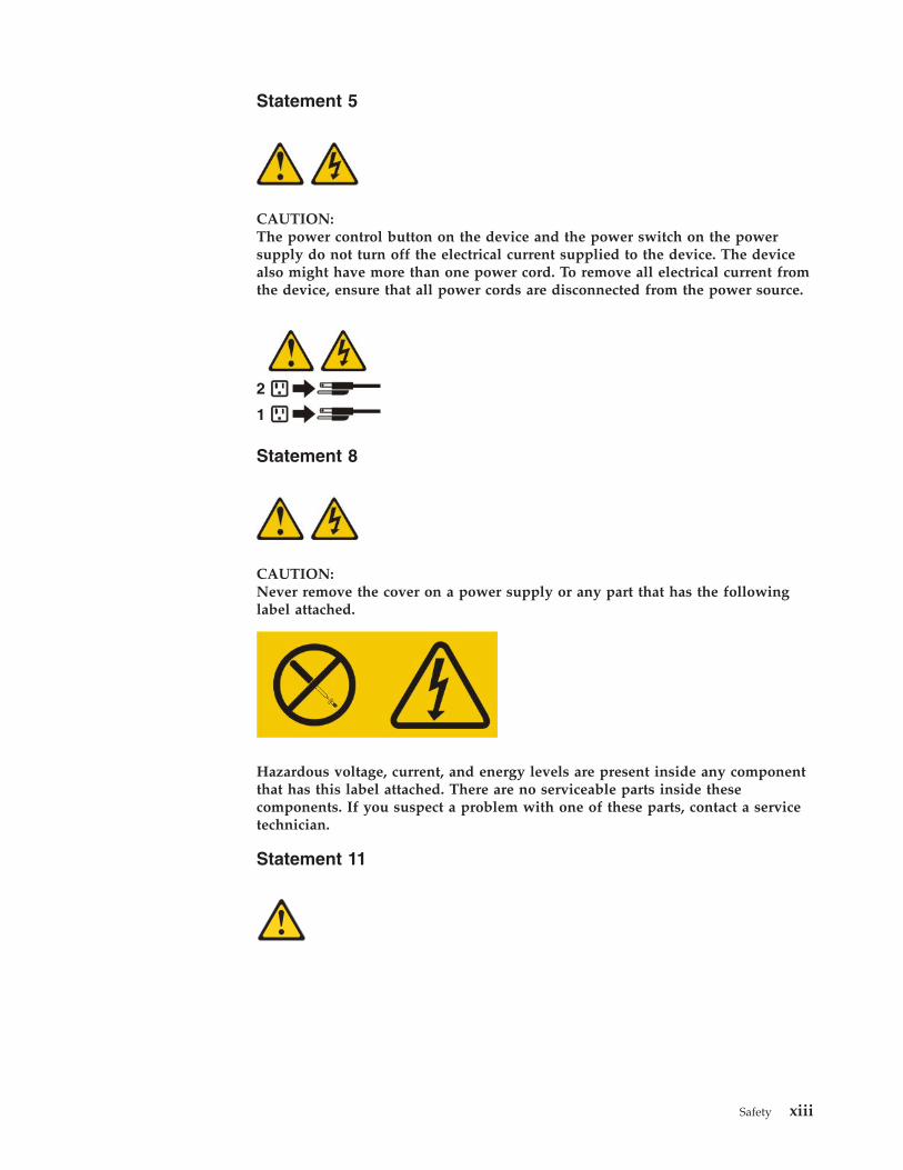
Statement 5
CAUTION:The power control button on the device and the power switch on the powersupply do not turn off the electrical current supplied to the device. The devicealso might have more than one power cord. To remove all electrical current fromthe device, ensure that all power cords are disconnected from the power source.
Statement 8
CAUTION:Never remove the cover on a power supply or any part that has the followinglabel attached.
Hazardous voltage, current, and energy levels are present inside any componentthat has this label attached. There are no serviceable parts inside thesecomponents. If you suspect a problem with one of these parts, contact a servicetechnician.
Statement 11
Safety xiii
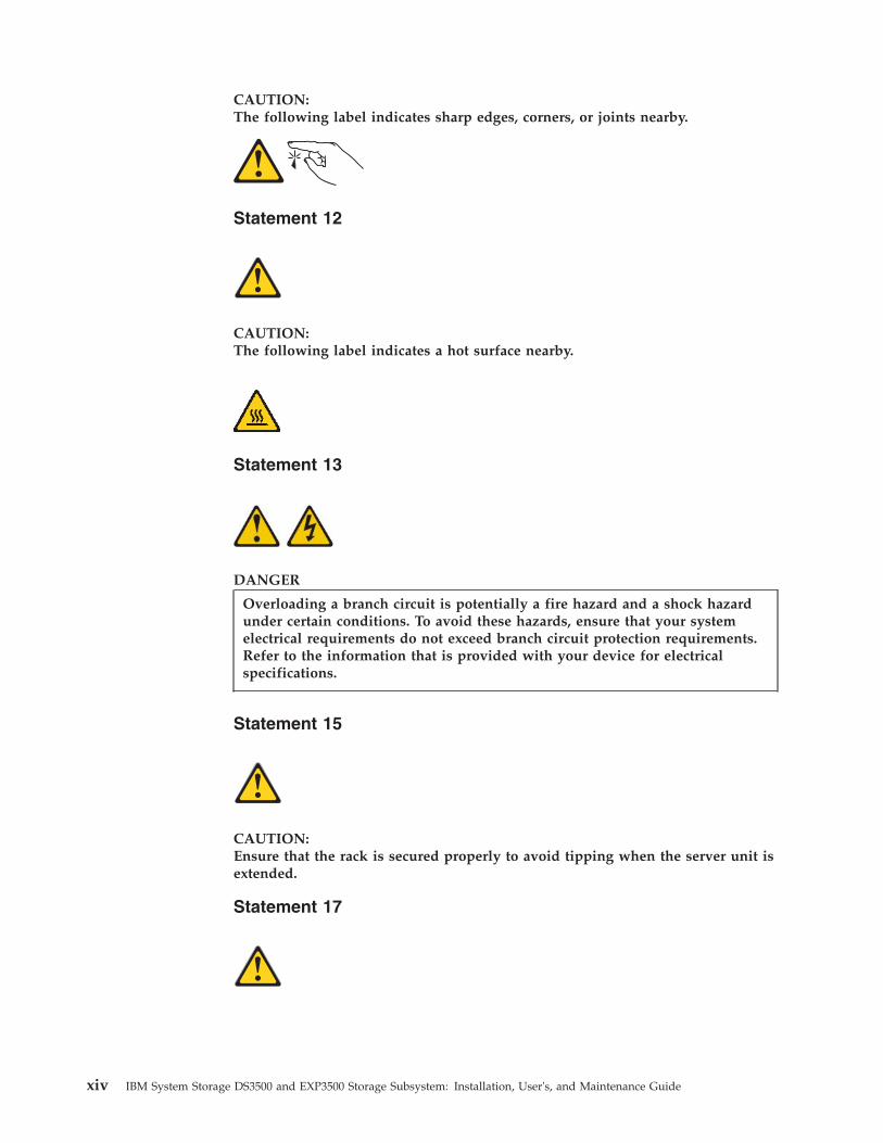
CAUTION:The following label indicates sharp edges, corners, or joints nearby.
Statement 12
CAUTION:The following label indicates a hot surface nearby.
Statement 13
DANGER
Overloading a branch circuit is potentially a fire hazard and a shock hazardunder certain conditions. To avoid these hazards, ensure that your systemelectrical requirements do not exceed branch circuit protection requirements.Refer to the information that is provided with your device for electricalspecifications.
Statement 15
CAUTION:Ensure that the rack is secured properly to avoid tipping when the server unit isextended.
Statement 17
xiv IBM System Storage DS3500 and EXP3500 Storage Subsystem: Installation, User's, and Maintenance Guide

CAUTION:The following label indicates moving parts nearby.
Statement 26
CAUTION:Do not place any object on top of rack-mounted devices.
Statement 29
CAUTION:This equipment is designed to permit the connection of the earthed conductor ofthe dc supply circuit to the earthing conductor at the equipment. If thisconnection is made, all of the following conditions must be met:
v This equipment shall be connected directly to the dc supply system earthingelectrode conductor or to a bonding jumper from an earthing terminal bar orbus to which the dc supply system earthing electrode conductor is connected.
v This equipment shall be located in the same immediate area (such as, adjacentcabinets) as any other equipment that has a connection between the earthedconductor of the same dc supply circuit and the earthing conductor, and alsothe point of earthing of the dc system. The dc system shall not be earthedelsewhere.
v The dc supply source shall be located within the same premises as thisequipment.
v Switching or disconnecting devices shall not be in the earthed circuitconductor between the dc source and the point of connection of the earthingelectrode conductor.
Statement 34
Safety xv

CAUTION:To reduce the risk of electric shock or energy hazards:
v This equipment must be installed by trained service personnel in arestricted-access location, as defined by the NEC and IEC 60950-1, FirstEdition, The Standard for Safety of Information Technology Equipment.
v Connect the equipment to a reliably grounded safety extra low voltage (SELV)source. An SELV source is a secondary circuit that is designed so that normaland single fault conditions do not cause the voltages to exceed a safe level (60V direct current).
v Incorporate a readily available approved and rated disconnect device in thefield wiring.
v See the specifications in the product documentation for the requiredcircuit-breaker rating for branch circuit overcurrent protection.
v Use copper wire conductors only. See the specifications in the productdocumentation for the required wire size.
v See the specifications in the product documentation for the required torquevalues for the wiring-terminal nuts.
Statement 37
DANGER
When you populate a rack cabinet, adhere to the following guidelines:
v Always lower the leveling pads on the rack cabinet.
v Always install the stabilizer brackets on the rack cabinet.
v Always install the heaviest devices in the bottom of the rack cabinet.
v Do not extend multiple devices from the rack cabinet simultaneously,unless the rack-mounting instructions direct you to do so. Multiple devicesextended into the service position can cause your rack cabinet to tip.
v If you are not using the IBM 9308 rack cabinet, securely anchor the rackcabinet to ensure its stability.
Attention: This product is suitable for use on an IT power distribution systemwhose maximum phase to phase voltage is 240 V under any distribution faultcondition.
Power and cabling information for NEBS (NetworkEquipment-Building System) GR-1089-CORE
The following comments apply to IBM storage devices that have been designatedas conforming to NEBS (Network Equipment-Building System) GR-1089-CORE.
The equipment is suitable for installation at:v Network telecommunications facilitiesv Locations where the NEC (National Electrical Code) applies.
xvi IBM System Storage DS3500 and EXP3500 Storage Subsystem: Installation, User's, and Maintenance Guide

CAUTION:Intra-building wiring (cabling) must be shielded and grounded at each endwhen used with the storage device.
Note:
v The intra-building ports of this equipment are suitable for connection tointra-building or unexposed wiring or cabling only. The intra-building ports ofthis equipment must not be metallically connected to the interfaces that connectto the OSP (outside plant) or its wiring. These interfaces are designed for use asintra-building interfaces only (Type 2 or Type 4 ports as described inGR-1089-CORE, issue 5 or latest revision) and require isolation from the exposedOSP cabling. The addition of primary protectors is not sufficient protection toconnect these interfaces metallically to OSP wiring.
v The ac-powered system does not require the use of an external surge protectiondevice (SPD).
v The dc-powered system employs an isolated DC return (DC-I) design. The DCbattery return terminal shall not be connected to the chassis or frame ground.
v The storage device (dc power) is intended to be installed in a Common BondingNetwork (or mesh network) as described in GR-1089-CORE, Issue 5 or latestrevision.
Safety xvii

xviii IBM System Storage DS3500 and EXP3500 Storage Subsystem: Installation, User's, and Maintenance Guide
Chapter 1. Introduction
This section contains information about the operating specifications, features, andcomponents of the IBM System Storage DS3500 storage subsystem and the IBMSystem Storage EXP3500 storage enclosure.
Note: For Ethernet Interfaces: DS3500 storage subsystem is not intended to beconnected directly or indirectly by any means whatsoever to interfaces of publictelecommunication networks.
The DS3500 storage subsystem and EXP3500 storage enclosure consist of thefollowing models:v DS3512 storage subsystemv DS3524 storage subsystemv EXP3512 storage enclosurev EXP3524 storage enclosure
This section also includes an inventory checklist and information about bestpractices and product updates for your DS3500 storage subsystem and EXP3500storage enclosure.
If firmware and documentation updates are available, you can download themfrom the IBM Web site. The DS3500 storage subsystem and EXP3500 storageenclosure might have features that are not described in the documents that areshipped with the device. Documents might be updated occasionally to includeinformation about those features, or technical updates might be available, whichare not included in the DS3500 storage subsystem and EXP3500 storage enclosuredocuments.
To check for updates, complete the following steps:1. Go to http://www.ibm.com/servers/storage/support/.2. On the “Support for System Storage® and TotalStorage products” page, under
Select your product, in the Product family field, select Disk systems.3. In the Product field, select DS3500 or EXP3500.4. Click Go.5. Select the following options:
v For firmware updates, click the Download tab.v For documentation updates, click the Install and use tab.
Note: Changes are made periodically to the IBM Web site. Procedures for locatingfirmware and documentation might vary slightly from what is described in thisdocument.
The DS3500 storage subsystem and EXP3500 storage enclosure have limitedwarranty. For more information about the terms of warranty, see the WarrantyInformation document that comes with the device.
Record information about the DS3500 storage subsystem and EXP3500 storageenclosure in “Storage subsystem and controller information record” on page 184.You will need this information if you have to call for service.
© Copyright IBM Corp. 2010, 2013 1
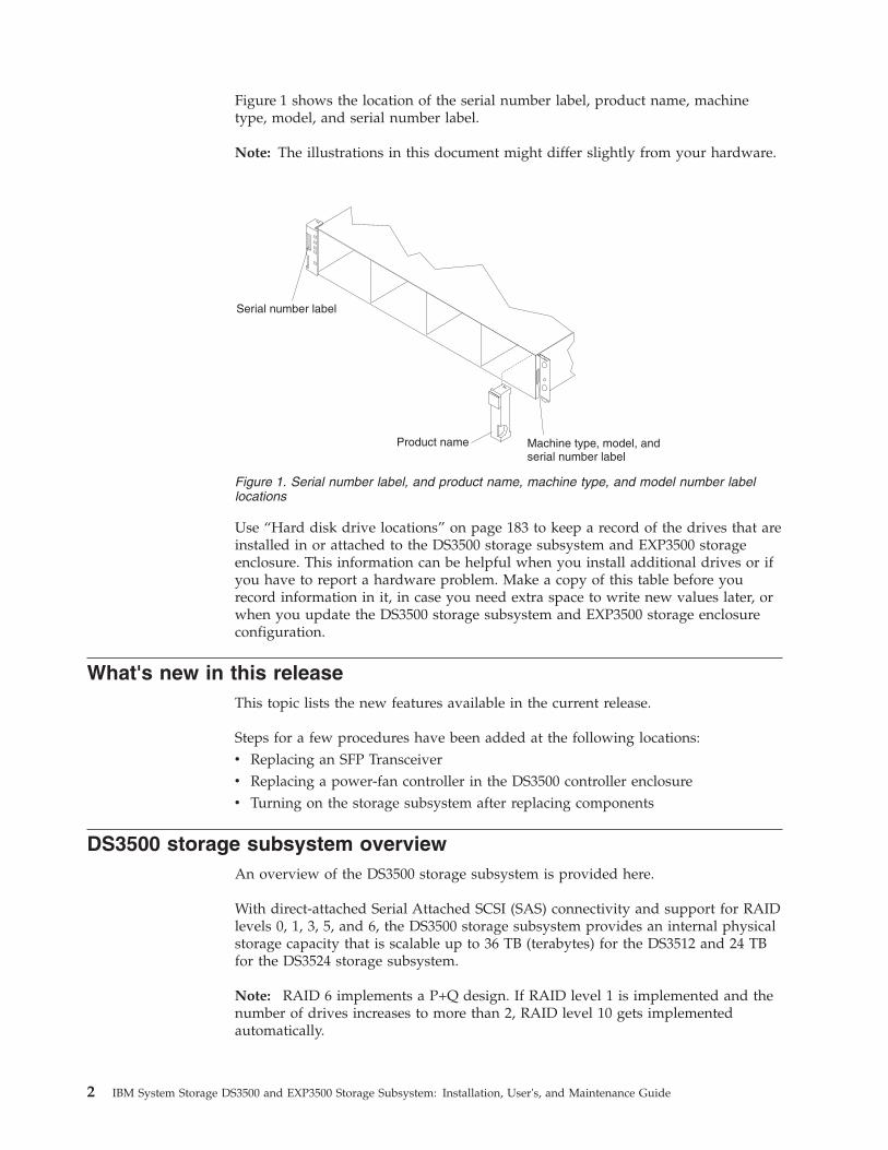
Figure 1 shows the location of the serial number label, product name, machinetype, model, and serial number label.
Note: The illustrations in this document might differ slightly from your hardware.
Use “Hard disk drive locations” on page 183 to keep a record of the drives that areinstalled in or attached to the DS3500 storage subsystem and EXP3500 storageenclosure. This information can be helpful when you install additional drives or ifyou have to report a hardware problem. Make a copy of this table before yourecord information in it, in case you need extra space to write new values later, orwhen you update the DS3500 storage subsystem and EXP3500 storage enclosureconfiguration.
What's new in this releaseThis topic lists the new features available in the current release.
Steps for a few procedures have been added at the following locations:v Replacing an SFP Transceiverv Replacing a power-fan controller in the DS3500 controller enclosurev Turning on the storage subsystem after replacing components
DS3500 storage subsystem overviewAn overview of the DS3500 storage subsystem is provided here.
With direct-attached Serial Attached SCSI (SAS) connectivity and support for RAIDlevels 0, 1, 3, 5, and 6, the DS3500 storage subsystem provides an internal physicalstorage capacity that is scalable up to 36 TB (terabytes) for the DS3512 and 24 TBfor the DS3524 storage subsystem.
Note: RAID 6 implements a P+Q design. If RAID level 1 is implemented and thenumber of drives increases to more than 2, RAID level 10 gets implementedautomatically.
Serial number label
Product name Machine type, model, andserial number label
Figure 1. Serial number label, and product name, machine type, and model number labellocations
2 IBM System Storage DS3500 and EXP3500 Storage Subsystem: Installation, User's, and Maintenance Guide
DS3500 is a 2U rack-mountable storage subsystem that supports up to tworedundant, dual-active RAID storage controllers. The DS3500 storage subsystemships with two 6 Gbps x4 SAS host ports and a single 6 Gbps x4 SAS expansionport per controller. Each controller contains 1 GB of cache memory that can beupgraded to 2 GB. Each controller supports installation of the following host portadapters:v 6 Gbps SASv 8 Gbps FCv 1 Gbps iSCSIv 10 Gbps iSCSI
When attached to EXP3500 storage enclosures, the DS3500 storage subsystem canbe expanded to support 96 drives. This configuration can be expanded to 192drives when using the 96-192 drive expansion upgrade. The DS3500 storagesubsystem and EXP3500 storage enclosures support configurations of 6 Gbps SAS,Near Line (NL) SAS, Solid State Disk (SSD), 6 Gbps SAS Full Disk Encryption(FDE) disk drives, or a mix of disk drives. You must purchase the Full DiskEncryption (FDE) option so that you can use FDE.
Advanced DS3500 storage management, copy service options, and optionaladvanced disaster recovery functions are available for the DS3500, includingFlashCopy®, VolumeCopy, and Enhanced Remote Mirroring.
Note: Enhanced Remote Mirroring is supported on the dual-controller DS3500models only.
Depending on the model, the DS3524 storage subsystems are shipped with eitherac or dc (-48V dc) power supply and fan units.
DS3524 storage subsystems that are equipped with dc power supply and fan units(1746 model C4T) supports both NEBS level 3/Telco operating environments andstandard Information Technology (IT) and office environments.
DS3512 and DS3524 storage subsystems that are equipped with ac power supplyand fan units support both NEBS level 3/Telco operating environments andstandard IT and office environments.
The IBM System Storage DS Storage Manager version 10 software is also availablefor the DS3500 storage subsystem. This storage-management software is designedto help centralize storage management, simplify partitioning of the DS3500 seriesstorage into as many as 128 virtual servers, and strategically allocate storagecapacity to maximize storage space.
Using the hot-swap features, you can remove and replace SAS drives, powersupplies, and controllers (in a dual-controller storage subsystem).
EXP3500 storage enclosure overviewAn overview of the EXP3500 storage subsystem is provided here.
The EXP3500 is a 2U rack-mountable storage enclosure that is equipped with asingle environmental services module (ESM), which can be expanded to dualredundant ESM when you install the optional ESM kit. The EXP3512 storageenclosure supports up to 12 drives and the EXP3524 storage enclosure supports upto 24 drives.
Chapter 1. Introduction 3

Depending on the model, the EXP3500 storage enclosures are shipped with eitherac or dc (-48V dc) power supply and fan units.
EXP3500 storage enclosures that are equipped with ac power supply and fan units(1746 models E2A and E4A) support both NEBS level 3/Telco operatingenvironments, and standard IT and office environments. EXP3524 storageenclosures that are equipped with dc power supply and fan units (1746 model E4Tonly) also support both NEBS level 3/Telco operating environments, and standardInformation Technology (IT) and office environments.
Notices and statements in this documentThe caution and danger statements in this document are also in the multilingualIBM Systems Safety Notices document, which is in the Documentation folder on theIBM System Storage DS3500 Support DVD. Each statement is followed by a referencenumber that you can use to locate the corresponding statement in your languagein the IBM Systems Safety Notices document.
The following notices and statements are used in this document:v Note: These notices provide important tips, guidance, or advice.v Important: These notices provide information or advice that might help you
avoid inconvenient or problem situations.v Attention: These notices indicate potential damage to programs, devices, or data.
An attention notice is placed just before the instruction or situation in whichdamage might occur.
v Caution: These statements indicate situations that can be potentially hazardousto you. A caution statement is placed just before the description of a potentiallyhazardous procedure step or situation.
v Danger: These statements indicate situations that can be potentially lethal orextremely hazardous to you. A danger statement is placed just before thedescription of a potentially lethal or extremely hazardous procedure step orsituation.
Features and operating specificationsThe features and operating specifications of the DS3500 storage subsystem arediscussed here.
Table 1 on page 5 contains a summary of the features and operating specificationsof the DS3500 storage subsystem and EXP3500 storage enclosure. Depending onthe model, some features might not be available, or some specifications might notapply.
4 IBM System Storage DS3500 and EXP3500 Storage Subsystem: Installation, User's, and Maintenance Guide

Table 1. Features and operating specifications
General:
v Modular components– High-capacity disk drives– (DS3500) RAID storage
controller modules– (EXP3500) environmental
services modules (ESMs)– Power supplies with built-in
fans
v Technology
– Supports disk subsystemtechnology
– Redundant data storage, powerand cooling system, (DS3500)SAS disk controllers, and(EXP3500) ESMs
– Hot-swap technology for drives,power supplies, (EXP3500)ESMs, and (DS3500) controllers
– (DS3500) Host port adapter.Each controller supports onehost port adapter. Support for:- 6 Gbps SAS- 8 Gbps FC- 1 Gbps iSCSI- 10 Gbps iSCSI
v User interface
– Built-in power, activity, and faultLEDs, identification labeling oncomponents, rear LEDs, andconnectors
– Easy-to-replace drives, powersupplies with built-in fans, andcontrollers
Power supply with built-in fans:
v Two hot-swap 585-watt (100 - 240V ac) standard
v Provides redundant power
Size:
v DS3512 and EXP3512:
– Height: 8.6 cm (3.4 in.)
– Depth: 54.0 cm (21.3 in.)
– Width: 44.9 cm (17.7 in.)
– (DS3512) Weight: Singlecontroller: 17.2 kg (38.0 lb) Dualcontroller: 18.5 kg (40.7 lb)
– (EXP3512) Weight: 16.9 kg (37.3lb)
v DS3524 and EXP3524:
– Height: 8.8 cm (3.5 in.)
– Depth: 48.7 cm (19.2 in.)
– Width: 44.9 cm (17.7 in.)
– (DS3524) Weight: Singlecontroller: 20.2 kg (44.5 lb) Dualcontroller: 21.4 kg (47.2 lb)
– (EXP3524) Weight: 19.9 kg (43.8lb)
Environment:v Air temperature:
– On: 10° to 35°C (50.0° to 95°F);altitude: 30.5 (100 ft) below to3000 m (9840 ft) above sea level;temperature change: 10°C (18°F)per hour
– Off: -10° to 50°C (14.0° to120.0°F); maximum altitude: 3000m (9840 ft); temperature change:15°C (27.0°F) per hour
v Humidity:– On: 20% to 80%– Off: 10% to 90%– Maximum dew point: 26°C (79°F)– Maximum humidity gradient:
10% per hour
Heat output:
Approximate heat output in Britishthermal units (Btu) per hour:v Minimum configuration: 205 Btu (60
watts)v Maximum configuration 1235 Btu
(361 watts)
Hard disk drives:v DS3512 and EXP3512: 12 LFF
3.5–inch 6 Gbpsv DS3524 and EXP3524: 24 SFF
2.5–inch 6 Gbps
Drive type: SAS, NL SAS, and SSD
Storage controllers:
(DS3500) SAS interface: Three 26-pin,mini-SAS connectors per controller
ESMs:
(EXP3500) SAS interface: Three26-pin, mini-SAS connectors per ESM
Acoustical noise emissions:
v DS3512 and EXP3512 fullypopulated with 12 drives
– Sound power (idling): 6.2 bels
– Sound power (operating): 6.2bels
– Sound pressure (idling): 62dBA
– Sound pressure (operating): 62dBA
v DS3524 and EXP3524 fullypopulated with 24 drives
– Sound power (idling): 6.4 bels
– Sound power (operating): 6.4bels
– Sound pressure (idling): 64dBA
– Sound pressure (operating): 64dBA
Electrical input (ac models):v Sine-wave input (50 - 60 Hz)
requiredv Input voltage low range:
– Minimum: 90 V ac– Maximum: 140 V ac
v Input voltage high range:– Minimum: 200 V ac– Maximum: 264 V ac
v Approximate input kilovolt-amperes(kVA):– Minimum: 0.06 kVA– Maximum: 0.38 kVA
Electrical input (dc models):v Input voltage range:
– Minimum: -42 V dc– Nominal: -48 V dc– Maximum: -60 V dc
v Operating current: 16 A to 11.2 A
Chapter 1. Introduction 5
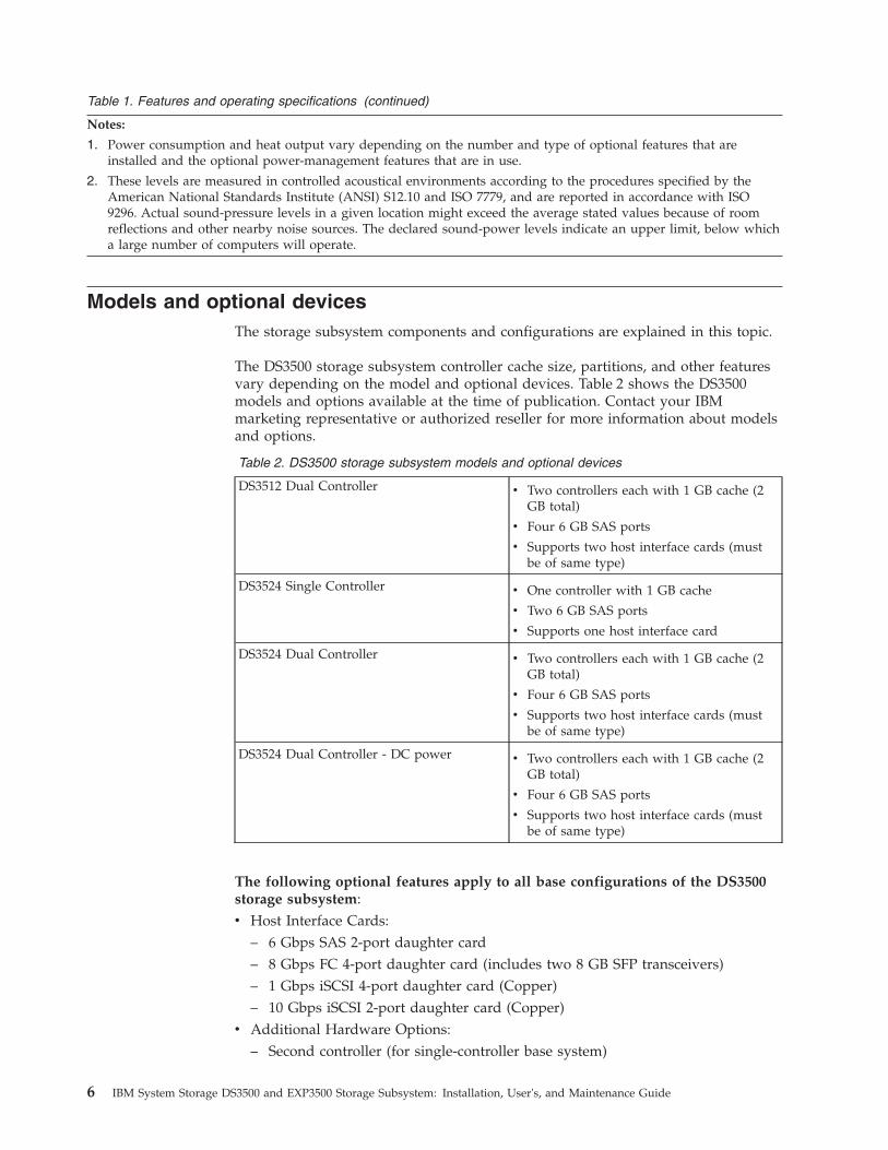
Table 1. Features and operating specifications (continued)
Notes:
1. Power consumption and heat output vary depending on the number and type of optional features that areinstalled and the optional power-management features that are in use.
2. These levels are measured in controlled acoustical environments according to the procedures specified by theAmerican National Standards Institute (ANSI) S12.10 and ISO 7779, and are reported in accordance with ISO9296. Actual sound-pressure levels in a given location might exceed the average stated values because of roomreflections and other nearby noise sources. The declared sound-power levels indicate an upper limit, below whicha large number of computers will operate.
Models and optional devicesThe storage subsystem components and configurations are explained in this topic.
The DS3500 storage subsystem controller cache size, partitions, and other featuresvary depending on the model and optional devices. Table 2 shows the DS3500models and options available at the time of publication. Contact your IBMmarketing representative or authorized reseller for more information about modelsand options.
Table 2. DS3500 storage subsystem models and optional devices
DS3512 Dual Controller v Two controllers each with 1 GB cache (2GB total)
v Four 6 GB SAS ports
v Supports two host interface cards (mustbe of same type)
DS3524 Single Controller v One controller with 1 GB cache
v Two 6 GB SAS ports
v Supports one host interface card
DS3524 Dual Controller v Two controllers each with 1 GB cache (2GB total)
v Four 6 GB SAS ports
v Supports two host interface cards (mustbe of same type)
DS3524 Dual Controller - DC power v Two controllers each with 1 GB cache (2GB total)
v Four 6 GB SAS ports
v Supports two host interface cards (mustbe of same type)
The following optional features apply to all base configurations of the DS3500storage subsystem:v Host Interface Cards:
– 6 Gbps SAS 2-port daughter card– 8 Gbps FC 4-port daughter card (includes two 8 GB SFP transceivers)– 1 Gbps iSCSI 4-port daughter card (Copper)– 10 Gbps iSCSI 2-port daughter card (Copper)
v Additional Hardware Options:– Second controller (for single-controller base system)
6 IBM System Storage DS3500 and EXP3500 Storage Subsystem: Installation, User's, and Maintenance Guide
– 8 Gbps FC SFP transceiver pair– 2 GB cache upgrade (quantity one for single controller, two for dual
controller)v Premium feature options:
– Turbo performance (requires dual controllers)– Full Disk Encryption (FDE)– Can add up to 192 drives in the storage subsystem (See Note 1)
– FlashCopy Logical Drive– Other Premium key feature options; these premium features can be activated
using IBM DS Storage Manager 10 controller firmware 7.84 and later:- Performance Read Cache- Disaster Recovery Option
v Enhanced Global Mirroringv Enhanced Remote Mirroring
- Backup & Restore Optionv Enhanced FlashCopy
- Super Keyv Performance Read Cachev Enhanced Global Mirroringv Enhanced Remote Mirroringv Enhanced FlashCopy
Note:
1. To obtain this optional capability, you must purchase a 96 to 192 driveexpansion premium feature.
Operating-system supportThis topic discusses the operating systems are supported for the DS3500 storagesubsystem.
The following operating systems are supported for host servers that have mappedLUNs created in the DS3500 storage subsystem with storage enclosures:v IBM AIX®
v IBM Linux on POWER® (LoP)v Microsoft Windows Server 2003v Microsoft Windows Server 2008v Microsoft Windows Server 2012v Red Hat® Enterprise Linuxv SuSE Linux Enterprise Serverv VMware ESX Serverv Oracle Solaris
For additional host operating-system support, see the latest Storage Managersoftware readme file and the IBM DS3000 series products interoperability matrix athttp://www.ibm.com/systems/storage/disk/.
Chapter 1. Introduction 7
Product updatesIf you need to update your DS3500 storage subsystem, follow the steps below.
Important: To keep your storage subsystem up-to-date with the latest firmwareand other product updates, register the storage subsystem for technical supportnotifications. Go to http://www.ibm.com/servers/storage/support/disk/. Fromthe menu at the top of the page, click My IBM and select My Technical Support.On the next page, click register now.
Download the latest version of the Storage Manager software, DS3500 storagesubsystem controller firmware, DS3500 series storage enclosure firmware, anddrive firmware when you initially install the storage subsystem and when productupdates become available.
To receive product updates, complete the following steps:1. After you have registered, type your user ID and password to log in to the site.
The “My notifications for technical support” page opens.2. From the Subscribe tab, click Storage disk systems.3. Click the box next to the product you want to receive information about.4. Click Continue.5. Under Notify me by, click e-mail.6. Click the Submit button to complete the notifications process.
Best practices guidelinesThis topic provides guidelines on best practices during the usage of the DS3500storage subsystem.
To ensure optimal operation of your system, follow these best practices:v Ensure that the storage subsystem is in an optimal state before you shut it
down. Never turn off the power if any amber LED is lit; be sure to resolve anyerror conditions before you shut down the storage subsystem.
v Back up the data on your storage drives periodically.v To maintain power redundancy, connect the DS3500 storage subsystem and
EXP3500 storage enclosure right and left power supplies to two independentexternal power circuits through ac power distribution units (PDUs) inside a rackor directly into external receptacles. This ensures that all devices in theconfiguration have power when only one power circuit is available. In addition,having all the right or all the left power cables connected to the same powercircuit enables the devices in the configuration to power-on simultaneouslyduring an unattended restoration of power.
Note: Do not overload the circuits that power your storage subsystem andstorage enclosures. Use additional pairs of ac PDUs. See Table 1 on page 5 forinformation about storage subsystem power requirements. Contact thetechnical-support representative for additional information.
v Save the storage subsystem profile before any planned system shutdown or afterany system additions, removals, or modifications (including firmware updates,logical drive creations, storage partitioning definitions, hardware changes, andso on). For instructions to save the storage subsystem profile for DS StorageManager V10.77 or earlier, see the IBM System Storage DS® Storage ManagerVersion 10 Installation and Host Support Guide. For DS Storage Manager V10.83 or
8 IBM System Storage DS3500 and EXP3500 Storage Subsystem: Installation, User's, and Maintenance Guide
later, see IBM System Storage DS Storage Manager Version 10.8 Installation and HostSupport Guide. Save the profile in a location other than in the logical drives thatare created for the DS3500 storage subsystem and EXP3500 storage enclosure.
v During any maintenance or attended power-on procedure, carefully follow thepower-on sequence that is described in “Turning on the storage subsystem” onpage 82. Ensure that each component of the storage subsystem is powered-on inthe correct order during this entire power-on procedure to ensure that thecontroller will be able to optimally access all of the storage subsystems.
v The storage subsystem supports simultaneous power-on to the systemcomponents. However, you must always follow the power-on sequence that isdescribed in “Turning on the storage subsystem” on page 82 during anyattended power-on procedure.
v A storage subsystem in an optimal state should recover automatically from anunexpected shutdown and unattended simultaneous restoration of power tosystem components. After power is restored, call your IBM technical-supportrepresentative if any of the following conditions occur:– The storage subsystem logical drives and subsystems do not display in the
Storage Manager graphical user interface.– The storage subsystem logical drives and subsystems are not online.– The storage subsystem logical drives and subsystems seem to be degraded.
v When using dc models equipped with dc power supply and fan units, install thedc disconnect/breaker device as described in “Cabling the DS3500 and EXP3500dc power supplies” on page 78.Attention:
– The disconnect device (circuit breaker) must be rated at 20 A.– Ensure that only 12 AWG or larger copper conductor wires are used for all of
the wiring between the DS3500 or EXP3500 dc power connectors and the dcpower source.
DS3500 storage subsystem and EXP3500 storage enclosurecomponents
The DS3500 storage subsystem and EXP3500 storage enclosures have removablecomponents, as described in this topic.
The DS3500 storage subsystem and EXP3500 storage enclosures have the followingremovable components. These components, called customer replaceable units(CRUs), are accessible from the front or rear of the storage subsystem.v (DS3512 and EXP3512) Up to 12 LFF 3.5–inch 6 Gbps SAS or NL SAS drives and
drive filler panels.v (DS3524 and EXP3524) Up to 24 SFF 2.5–inch 6 Gbps SAS, NL SAS, or SSD
drives and drive filler panels.v (DS3512 and DS3524) Up to two controllers. Each controller supports the
installation one of the following optional host port adapters:– 6 Gbps SAS– 8 Gbps FC– 1 Gbps iSCSI– 10 Gbps iSCSI
v (EXP3512 and EXP3524) Up to two ESM modules.v Two ac power supply and fan units (machine type 1746 models C2A, E2A, C4A,
and E4A).
Chapter 1. Introduction 9

v Two dc power supply and fan units (machine type 1746 models C4T and E4T).
Disk drives and bezelsAn in-depth look at how disk drives and bezels are set up in the DS3500 storagesubsystem.
The hot-swap drive bays that are accessible from the front of the DS3512 storagesubsystem and EXP3512 storage enclosure are shown in Figure 2. The hot-swapdrive bays that are accessible from the front of the DS3524 storage subsystem andEXP3524 storage enclosure are shown in Figure 3.
Hot-swap driveYou can install up to 12 hot-swap SAS or NL SAS drives in the DS3512storage subsystem and EXP3512 storage enclosure. You can install up to 24hot-swap SAS or NL SAS drives in the DS3524 storage subsystem andEXP3524 storage enclosure.
Filler panelThe DS3500 storage enclosure and EXP3500 storage enclosure have fillerpanels in the empty drive bays. Before you install a disk drive, remove thefiller panel and save it for future use. Each of the drive bays must containeither a filler panel or a drive.
Left-side bezelThe left-side bezel contains the LEDs, as shown in the followingillustration. For a description of the LEDs, see “Front LEDs” on page 89.
Hot-swap hard disk drive Filler panel
Bezels
Figure 2. DS3512 storage subsystem and EXP3512 storage enclosure hot-swap drive baysand bezels
Figure 3. DS3524 storage subsystem and EXP3524 storage enclosure hot-swap drive baysand bezels
10 IBM System Storage DS3500 and EXP3500 Storage Subsystem: Installation, User's, and Maintenance Guide

Right-side bezel and bottom shelfThe right-side bezel and bottom shelf contain the drive identificationinformation. Figure 5 shows the right-side bezel of the DS3512 storagesubsystem and EXP3512 storage enclosure. Figure 6 shows the bottom shelfof the DS3524 storage subsystem and EXP3524 storage enclosure.
The drives are preinstalled in drive enclosures. Install drives in the drive bays onthe front of the storage subsystem or storage enclosure. When a drive is installed,the drive and enclosure bay designation is set automatically. The hardwareaddresses are based on the enclosure ID setting on the controller and on thephysical locations of the drives.
There are no serviceable parts in a drive assembly. If it fails, the whole driveassembly, along with the drive, bezel, and enclosure, must be replaced. When you
Power-on LED
System locator LED
System error LED
Overtemperature LED
Standby power LED
Figure 4. Left-side bezel
Drives 1 - 4
Drives 5 - 8
Drives 9 - 12
Figure 5. Right-side bezel (DS3512 and EXP3512)
1 2 3 4 5 6 7 8 9 10 11 12 13 14 15 16 17 18 19 20 21 22 23 24
Drives 1 - 24
Figure 6. Bottom shelf (DS3524 and EXP3524)
Chapter 1. Introduction 11

replace a drive, ensure that you order the correct drive. Using an unsupporteddrive can cause the drive to be locked out by the controller firmware.
Attention:
1. After you remove a drive from a bay, wait for 70 seconds to allow the drive tospin down before you replace or reseat the drive. Failure to do so might causeunpredictable results.
2. Never hot-swap a drive when its associated green activity LED or amber faultLED is flashing. Hot-swap a drive only when its associated amber fault LED islit continuously or when the drive is inactive and its associated green activityLED is not flashing.
Note: If the drive that you want to remove is not in a failed or bypass state, usethe Storage Manager software either to place the drive in a failed state or to placethe subsystem that is associated with the drive (or drives) in an offline state, beforeyou remove the drive from the enclosure.
ControllersThe DS3500 storage subsystem controllers are discussed in this topic.
The DS3500 storage subsystem comprises one or two controllers. When the DS3500storage subsystem has two controllers, the controllers are redundant and can behot-swapped. The controllers contain the storage subsystem control logic, interfaceports, and LEDs. Each controller contains the following ports:v Two 6 Gbps SAS host portsv One SAS drive port to connect EXP3500 storage enclosuresv Two Ethernet ports for subsystem managementv Support for one optional host port adapter:
– Two-port 6 Gbps SAS– Four-port 8 Gbps FC– Four-port 1 Gbps iSCSI– Two-port 10 Gbps iSCSI
The Ethernet ports consist of the following default IP addresses:Port 1 on controller A is 192.168.128.101Port 2 on controller A is 192.168.129.101Port 1 on controller B is 192.168.128.102Port 2 on controller B is 192.168.129.102
The subnet mask for both Ethernet ports is 255.255.255.0.
Attention: When a DS3500 storage subsystem has two controllers, the controllersmust be identical to each other in hardware (host port adapter and cache size) andfirmware. If you install a host port adapter in one controller, you must install anidentical host port adapter in the other controller.
The storage management software automatically sets the enclosure ID for thecontrollers. You can change the enclosure ID through the Storage Manager softwareonly. There are no switches on the DS3500 chassis to manually set the enclosure ID.Both controller enclosure IDs are identical under normal operating conditions.
Figure 7 on page 13 shows a single-controller storage subsystem without anoptional host port adapter installed. See “Cabling the DS3500 storage subsystem”on page 31 for illustrations of the storage subsystem with optional host port
12 IBM System Storage DS3500 and EXP3500 Storage Subsystem: Installation, User's, and Maintenance Guide

adapters installed in the controllers.
Note: IBM DS Storage Manager password reset: Password reset clears thepassword to log in to the IBM DS Storage Manager. Press this button if you haveforgotten the password.
Environmental service modulesThe EXP3500 storage enclosure comprises a single environmental service module(ESM). An optional ESM is available for redundant configurations.
If the controller connected to the ESM supports more than one EXP3500 storageenclosure per physical port, you can connect two or more EXP3500 storageenclosures by chaining them together. For information about connecting anEXP3500 storage enclosure to a DS3500 storage subsystem, see “Connecting storageenclosures to the DS3500” on page 48.
Figure 8 shows an EXP3512 storage enclosure containing one ESM and a fillerpanel over the blank ESM bay.
AC power supply and fan unitsThe DS3500 storage subsystem (models DS3512-C2A and DS3524-C4A) andEXP3500 storage enclosure (models EXP3512-E2A and EXP3524-E4A) each havetwo removable ac power supplies.
Each ac power supply has two fans. The four fans pull air through the drives fromfront to back across the drives. The fans provide redundant cooling, which meansthat if one fan fails, the remaining fans continue to provide sufficient cooling tooperate the storage subsystem or storage enclosure. If one power supply is turned
Hot-swap power supplies
RAID controller A Filler panelPassword reset
dg1fy
035
Figure 7. Rear view, single-controller model (shown without an optional host port adapter)
Hot-swap power supplies
Filler panelESM
1 2
ESM
Figure 8. Rear view, single ESM model storage enclosure
Chapter 1. Introduction 13
off or malfunctions, the other power supply maintains electrical power to thestorage subsystem or storage enclosure. To preserve the optimal airflow, do notremove a failed power supply from the chassis until you are ready to replace itwith a new power supply.
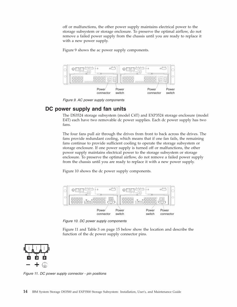
Figure 9 shows the ac power supply components.
DC power supply and fan unitsThe DS3524 storage subsystem (model C4T) and EXP3524 storage enclosure (modelE4T) each have two removable dc power supplies. Each dc power supply has twofans.
The four fans pull air through the drives from front to back across the drives. Thefans provide redundant cooling, which means that if one fan fails, the remainingfans continue to provide sufficient cooling to operate the storage subsystem orstorage enclosure. If one power supply is turned off or malfunctions, the otherpower supply maintains electrical power to the storage subsystem or storageenclosure. To preserve the optimal airflow, do not remove a failed power supplyfrom the chassis until you are ready to replace it with a new power supply.
Figure 10 shows the dc power supply components.
Figure 11 and Table 3 on page 15 below show the location and describe thefunction of the dc power supply connector pins.
Powerswitch
Powerconnector
Powerswitch
Powerconnector
Figure 9. AC power supply components
Powerswitch
Powerconnector
Powerswitch
Powerconnector
Figure 10. DC power supply components
Figure 11. DC power supply connector - pin positions
14 IBM System Storage DS3500 and EXP3500 Storage Subsystem: Installation, User's, and Maintenance Guide

Table 3. DC power supply connector - pin descriptions
Number Description
1 Pin 1: - 48 V dc
2 Pin 2: POS RTN
3 Pin 3: GND
Battery unitsEach controller contains 1024 MB of cache memory (minimum). It also contains asealed, rechargeable lithium ion battery that maintains data in the cache so that itcan be transferred to flash memory if power fails.
Figure 12 shows the locations of the battery and memory cache DIMM in thecontroller.
The battery chargers in the power supplies perform a battery learn test when thestorage subsystem is started for the first time and at a scheduled intervalthereafter. Data caching starts after the battery tests are completed.
The condition of the battery is indicated by an LED on the rear of the controller(see “Controller LEDs” on page 90 for the location of the battery fault LED andconditions that the LED indicates). You can also check the status of the batteryusing the Storage Manager client software.
Software and hardware compatibility and upgradesThe latest controller firmware, NVSRAM firmware, ESM firmware, and drivefirmware must be installed to ensure optimal functionality, manageability, andreliability.
Software and firmware support code upgradesTo enable support for the DS3500 storage subsystem, you must ensure that thesystem software and firmware are of the latest versions. To find the latest StorageManager software, controller firmware, NVSRAM, ESM firmware, and drivefirmware, check the firmware readme files.
Battery connector
Captive fastener
Memory cache battery
Memorycache DIMM
Host adapteror filler panel
Figure 12. Battery unit
Chapter 1. Introduction 15
The DS3500 was initially shipped with controller firmware version 7.70.16.01. Withcontroller firmware version 7.77.xx.xx, the following capabilities and support areavailable:v Standard feature extended capabilities added with controller firmware version
7.77.xx.xx:– The number of supported logical drives per subsystem is increased to 512
from 256.– The number of logical drives that can be assigned to a host partition is
increased to 256 from 32.v Premium feature extended capabilities added with controller firmware version
7.77.xx.xx:– The number of drives per subsystem can be increased to 192 from 96. To
obtain this optional capability, you must purchase a 96 to 192 drive expansionpremium feature.
– The number of host partitions supported per subsystem can be increased to128 from 64. To obtain this optional support, you must purchase theappropriate host partition upgrade premium feature for the currently enabled4, 8, 16, 32 or 64 host partitions.
– The number of FlashCopy logical drives per subsystem is increased to 256from 64. To obtain this capability, you must purchase a FlashCopy premiumfeature. No additional purchase is required.
– The number of VolumeCopy logical drives per subsystem is increased to 256.To obtain this optional capability, you must purchase a VolumeCopy premiumfeature. No additional purchase is required.
– The number of remote mirroring logical drives can be increased to 16 from 8.To obtain this optional support, you must purchase an 8 to 16 mirrorsupgrade premium feature in addition to the standard remote mirroringpremium feature.
v Hardware support added with controller firmware version 7.77.xx.xx:– 10 Gbps iSCSI host card– DS3524 model with DC power supplies
v The controller firmware version 7.83.xx.xx supports the following features:– Dynamic disk pooling– Thin provisioning– Enhanced FlashCopy– ALUA fail-over method
v The controller firmware version 7.84.xx.xx supports the following features:– Disaster Recovery Option (Enhanced FlashCopy)– Backup & Restore Option (Remote Mirroring and Enhanced Remote
Mirroring)– Performance Read Cache– Super Key (this key activates all features)
v In addition to supporting the above features, controller firmware version7.86.xx.xx supports the following hard disk feature:– T10 Protection Information (T10 PI or T10PI).
For instructions to install the DS Storage Manager V10.77 or earlier, see the IBMSystem Storage DS Storage Manager Version 10 Installation and Host Support Guide. Forinstructions to install the DS Storage Manager V10.83 or later, see the IBM SystemStorage DS Storage Manager Version 10.8 Installation and Host Support Guide.
16 IBM System Storage DS3500 and EXP3500 Storage Subsystem: Installation, User's, and Maintenance Guide
Determining firmware levelsTo determine the firmware levels of the DS3500 storage subsystem, the connectedstorage enclosures, and the installed drives, use the Storage Manager software thatis used to manage the DS3500 storage subsystem.1. In the Subsystem Management window, click the Summary tab.2. In the Status section, click Storage Subsystem Profile. The Storage Subsystem
Profile window opens.3. Click the All tab and scroll through the Profile For Storage Subsystem to
locate the following information:
Note: The Profile For Storage Subsystem contains profile information for theentire subsystem. Therefore, you might have to scroll through a large amount ofinformation to locate the firmware version numbers.
DS3500 Storage Server
v Firmware versionv NVSRAM version
Hard Disk Drives
v Firmware version
Drive Enclosure
v ESM firmware version
SpecificationsSpecifications of the DS3500 storage subsystem are covered in this topic.
The specifications of the DS3500 storage subsystem and EXP3500 storage enclosureare listed in Table 1 on page 5. This section provides additional site specificationsfor the DS3500 storage subsystem and EXP3500 storage enclosure. Before youinstall the storage subsystem, you must either check that the planned installationsite meets these requirements, or prepare the site so that it meet theserequirements. Preparations might include area, environmental, and electricalrequirements for DS3500 storage subsystem and EXP3500 storage enclosureinstallation, service, and operation.
Area requirementsThe floor space at the installation site must support the weight of the storagesubsystem and associated equipment; provide sufficient space to install, operate,and service the storage subsystem; and provide sufficient ventilation to providefree flow of air to the unit.
DimensionsThe dimensions of the DS3500 storage subsystem is explained in this topic.
Figure 13 on page 18 shows the dimensions of the DS3512 storage subsystem andEXP3512 storage enclosure, which conforms to the 19-inch rack standard.
Chapter 1. Introduction 17
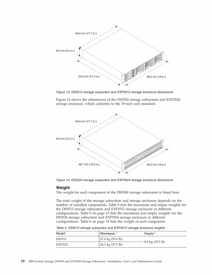
Figure 14 shows the dimensions of the DS3524 storage subsystem and EXP3524storage enclosure, which conforms to the 19-inch rack standard.
WeightThe weight for each component of the DS3500 storage subsystem is listed here.
The total weight of the storage subsystem and storage enclosure depends on thenumber of installed components. Table 4 lists the maximum and empty weights forthe DS3512 storage subsystem and EXP3512 storage enclosure in differentconfigurations. Table 5 on page 19 lists the maximum and empty weights for theDS3524 storage subsystem and EXP3524 storage enclosure in differentconfigurations. Table 6 on page 19 lists the weight of each component.
Table 4. DS3512 storage subsystem and EXP3512 storage enclosure weights
Model Maximum 1 Empty 2
DS3512 27.0 kg (59.6 lb)8.4 kg (18.5 lb)
EXP3512 26.3 kg (57.9 lb)
48.2 cm (19 in.)
44.9 cm (17.7 in.)
8.6 cm (3.4 in.)
54.0 cm (21.3 in.)
Figure 13. DS3512 storage subsystem and EXP3512 storage enclosure dimensions
48.2 cm (19 in.)
44.9 cm (17.7 in.)
8.8 cm (3.5 in.)
48.7 cm (19.2 in.)
Figure 14. DS3524 storage subsystem and EXP3524 storage enclosure dimensions
18 IBM System Storage DS3500 and EXP3500 Storage Subsystem: Installation, User's, and Maintenance Guide
Table 4. DS3512 storage subsystem and EXP3512 storage enclosure weights (continued)
Model Maximum 1 Empty 2
1 Chassis with dual controller or ESMs and 12 drives.
2 Chassis without power supplies, controllers or ESMs, and drive filler panels.
Table 5. DS3524 storage subsystem and EXP3524 storage enclosure weights
Model Maximum 1 Empty 2
DS3524 with ac powersupply and fan units
25.9 kg (57.1 lb)
10.7 kg (23.6 lb)
DS3524 with dc powersupply and fan units
25.85 kg (56.99 lb)
EXP3524 with ac powersupply and fan units
25.2 kg (55.5 lb)
EXP3524 with dc powersupply and fan units
25.15 kg (55.45 lb)
1 Chassis with dual controller or ESMs and 24 drives.
2 Chassis without power supplies, controllers or ESMs, and drive filler panels.
Table 6. DS3500 component weights
Unit Weight
2.5–inch drive 0.25 kg (0.55 lb)
3.5–inch drive 0.78 kg (1.72 lb)
AC power supply with fan 2.50 kg (5.31 lb)
DC power supply with fan 2.36 kg (5.21 lb)
Controller (including cache battery backupand no host port adapter)
2.05 kg (4.52 lb)
Fibre channel host daughter card .08 kg (.18 lb)
iSCSI host daughter card .05 kg (.11 lb)
SAS host daughter card .07 kg (.15 lb)
Battery .15 kg (.33 lb)
ESM 1.75 kg (3.86 lb)
Temperature and humidityThe temperature and humidity requirements to operate the DS3500 storagesubsystem are specified in this topic.
Table 7 on page 20 lists the acceptable temperature and humidity ranges for thestorage subsystem in typical Information Technology (IT) or office environments.
Chapter 1. Introduction 19

Table 7. Temperature and humidity requirements for storage subsystems in an InformationTechnology (IT) or office environment
Condition Parameter Requirement
Temperature (storagesubsystem On)
Operating range 10° to 35°C (50.0° to 95°F)
Altitude 30.5 (100 ft) below to 3000 m(9840 ft) above sea level
Maximum rate of change 10°C (18°F) per hour
Relative humidity (storagesubsystem On)
Operating range 20% to 80%
Maximum dew point 26°C (79°F)
Maximum humidity gradient 10% per hour
Temperature (storagesubsystem Off)
Operating range -10° to 50°C (14.0° to 120.0°F)
Maximum altitude 3000 m (9840 ft)
Maximum rate of change 15°C (27.0°F) per hour
Relative humidity (storagesubsystem Off)
Operating range 10% to 90%
Maximum dew point 26°C (79°F)
Maximum humidity gradient 10% per hour
Note:
1. The non-operating environment must not exceed the environment limits for more than60 days.
2. The storage environment must not exceed the environment limits for more than oneyear.
3. Substantial deviations from the suggested operating range, in either direction, ifsustained for extended periods of time, will expose the unit to greater risk of failurefrom external causes.
Table 8 lists temperature and humidity ranges for the storage subsystem in aNEBS/ETSI compliant environment.
Table 8. Temperature and humidity requirements for storage subsystems in a NEBS/ETSIcompliant environment
Condition Parameter Requirement
Temperature1 Operating range 5° - 40° C (41° - 104° F)
Short-term2 -5° - 50° C (23° - 122° F)
Maximum rate of change 30° C (54° F) per hour
Relative humidity1 (nocondensation)
Operating range 5% to 85%
Short-term2 5% to 90% (not to exceed0.024 kg water/kg of dry air)
Note:
1. In a NEBS/ETSI compliant environment, conditions are measured at a location 1.5 m (59in.) above the floor and 400 mm (15.8 in.) in front of the equipment.
2. Short-term refers to a period of not more than 96 consecutive hours and a total of notmore than 15 days in one year. (This refers to a total of 360 hours in any given year, butno more than 15 occurrences during that one-year period.)
Electrical requirementsThe electrical requirements to operate the DS3500 storage subsystem are specifiedin this topic.
20 IBM System Storage DS3500 and EXP3500 Storage Subsystem: Installation, User's, and Maintenance Guide

Consider the following information when you prepare the installation site:v Protective ground: Site wiring must include a protective ground connection to
the ac power source.
Note: Protective ground is also known as safety ground or chassis ground.v Circuit overloading: Power circuits and associated circuit breakers must provide
sufficient power and overload protection. To prevent possible damage to theunit, isolate its power source from large switching loads (such as airconditioning motors, elevator motors, and factory loads).
v Power failures: If a total power failure occurs, the unit automatically performs apower-on recovery sequence without operator intervention after power isrestored.
Site wiring and powerThe site wiring and power requirements to operate the DS3500 storage subsystemare specified in this topic.
The DS3500 storage subsystem (models DS3512-C2A and DS3524-C4A) andEXP3500 storage enclosure (models EXP3512-E2A and EXP3524-E4A) are equippedwith redundant ac power supply and fan units. The storage subsystem ac powersupplies are wide-ranging units that automatically accommodate voltages to the acpower source. The power supplies operate within the range of 90 V ac to 264 V ac,at a minimum frequency of 50 Hz and a maximum frequency of 60 Hz. The powersupplies meet standard voltage requirements for operation both inside the U.S.A.and outside the U.S.A. They use standard industrial wiring with line-to-neutral orline-to-line power connections. The ac power supplies have C14 power inlets.
Power requirements for models equipped with ac power supplies are shown inTable 9.
Table 9. DS3500 ac power requirements
Low range High range
Nominal voltage 90 V ac to 140 V ac 200 V ac to 264 V ac
Frequency (Hz) 50 to 60 Hz 50 to 60 Hz
Approximate inputkilovolt-amperes (kVA)
Minimum 0.06 kVA to maximum 0.38 kVA
The DS3524 model C4T storage subsystem and EXP3524 model E4T storageenclosure are equipped with redundant dc power supply and fan units. Thestorage subsystem dc power supplies are wide-ranging units that automaticallyaccommodate voltages to the dc power source. The dc power supplies operatewithin the range of -42 V dc to -60 V dc. The dc power supplies require a reliablygrounded safety extra-low voltage SELV source and an approved and rated 20 Adisconnect device for the -48 V line.
Power requirements for models equipped with dc power supplies are shown inTable 10.
Table 10. DS3500 dc power requirements
Requirement
Operating voltage -42 V to -60 V
Nominal voltage -48 V
Chapter 1. Introduction 21

Table 10. DS3500 dc power requirements (continued)
Requirement
Operating current 16 A to 11.2 A
Rated disconnect device (circuit-breaker) 20 A
Power recoveryAfter normal power is restored after a total ac or dc power failure, the storagesubsystem performs power-on recovery procedures automatically without operatorintervention.
Power cords and receptaclesThe specifications of power cords and receptacles required to operate the DS3500storage subsystem are listed in this topic.
Storage subsystems equipped with ac power supply and fan units come with twoac jumper cords that are used to connect to the rack PDU. You must purchase thepower cords that are applicable for use in a typical receptacle in your country. See“Power cords” on page 179 for more information.
Storage subsystems equipped with dc power supply and fan units come with twodc jumper cables that are used to connect to the site -48 V dc power source. Thesupplied dc jumper cables have 10 AWG copper conductor wires. 12 AWG orlarger copper conductor wires must be used for all of the wiring between theDS3500 or EXP3500 dc power connectors and the dc power source. See the“DS3524 storage subsystem and EXP3524 storage enclosure parts listing” on page177 for more information.
Heat output, airflow, and coolingThe heat output, airflow, cooling configurations requirements, and best practices tooperate the DS3500 storage subsystem are specified in this topic.
Air enters at the front of the DS3500 storage subsystem and EXP3500 storageenclosure and leaves at the back. Allow at least 30 inches in front of the DS3500storage subsystem and EXP3500 storage enclosure and at least 24 inches at the rearfor service clearance, proper ventilation, and heat dissipation.
When racks that contain many DS3500 storage subsystems and EXP3500 storageenclosures are to be installed together, the following requirements must be met toensure that the devices are adequately cooled:v Air enters at the front of the rack and leaves at the back. To prevent the air that
is leaving the rack from entering the intake of another piece of equipment, youmust position the racks in alternate rows, back-to-back and front-to-front. Thisarrangement is known as “cold aisle/hot aisle” and is shown in Figure 15 onpage 23.
v Where racks are in rows, each rack must touch the rack that is next to it toreduce the amount of hot air that can flow around from the back of the rack intothe intakes of the storage enclosures that are in that rack. Use Suite Attach Kitsto completely seal any gaps that remain between the racks. For details aboutSuite Attach Kits, contact your IBM marketing representative or authorizedreseller.
v Where racks are in rows front-to-front or back-to-back, gaps of at least 122 cm(48 in.) must separate the rows across the cold aisle (see Figure 15 on page 23).
22 IBM System Storage DS3500 and EXP3500 Storage Subsystem: Installation, User's, and Maintenance Guide
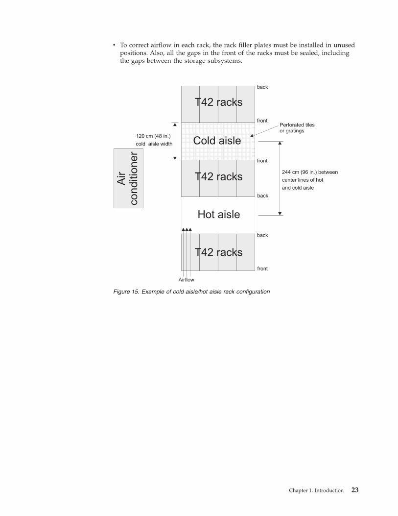
v To correct airflow in each rack, the rack filler plates must be installed in unusedpositions. Also, all the gaps in the front of the racks must be sealed, includingthe gaps between the storage subsystems.
120 cm (48 in.)
cold aisle width
244 cm (96 in.) between
center lines of hot
and cold aisle
Perforated tilesor gratings
back
back
T42 racks
T42 racks
T42 racks
Hot aisle
Air
co
nd
itio
ne
r
back
front
front
front
Airflow
Cold aisle
Figure 15. Example of cold aisle/hot aisle rack configuration
Chapter 1. Introduction 23

24 IBM System Storage DS3500 and EXP3500 Storage Subsystem: Installation, User's, and Maintenance Guide

Chapter 2. Installing the storage subsystem and storageenclosure
This section provides instructions for installing the DS3500 storage subsystem andthe EXP3500 storage enclosure in a rack.
To install the DS3500 storage subsystem in a rack, see Chapter 2, “Installing thestorage subsystem and storage enclosure.” To install the EXP3500 storage enclosurein a rack, see “Installing the EXP3500 storage enclosure” on page 29.
Before you begin the installation, review the safety information in “Safety” on pageix and “Handling static-sensitive devices” on page 27.
Installing the DS3500 storage subsystemThis section provides instructions for installing the DS3500 storage subsystem in arack.
Inventory checklistGuidelines on verifying the inventory checklist is listed here.
After you unpack the DS3500 storage subsystem, ensure that you have thefollowing items. Depending on your order, your shipping box might containadditional items that are not on the list.v Hardware
– Hard disk drives or drive filler panels:- DS3512 (12)- DS3524 (24)
– Storage controllers (up to 2)– AC power supply and fan units (2) (models C2A, E2A, C4A, and E4A)– DC power supply and fan units (2) (models C4T and E4T)– AC power cables (2 jumper line cords) (models C2A, E2A, C4A, and E4A)– DC power jumper cables (2) (models C4T and E4T)– Rack installation hardware kit:
- Support rails (2) (right and left assembly)- M5 black hex-head slotted screws (8)- M5 Washers (6)- Small diameter spacers (8) (these come installed, four in each rail)- Large diameter spacers (8)- M4 pan-head screws (2)
Attention: The DS3500 storage subsystem ac power models do not haveregion-specific power cords. You must obtain the IBM-approved ac power cordsfor your region. The DS3500 and EXP3500 dc power models do not have the 20A rated disconnect device (circuit-breaker) that is required for the -48V DCpower connection. See “Power cords” on page 179 for the IBM-approved acpower cords for your region.
v Software and documentation
© Copyright IBM Corp. 2010, 2013 25
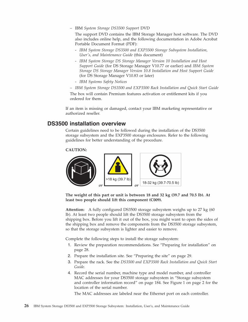
– IBM System Storage DS3500 Support DVDThe support DVD contains the IBM Storage Manager host software. The DVDalso includes online help, and the following documentation in Adobe AcrobatPortable Document Format (PDF):- IBM System Storage DS3500 and EXP3500 Storage Subsystem Installation,
User's, and Maintenance Guide (this document)- IBM System Storage DS Storage Manager Version 10 Installation and Host
Support Guide (for DS Storage Manager V10.77 or earlier) and IBM SystemStorage DS Storage Manager Version 10.8 Installation and Host Support Guide(for DS Storage Manager V10.83 or later)
- IBM Systems Safety Notices
– IBM System Storage DS3500 and EXP3500 Rack Installation and Quick Start Guide
The box will contain Premium features activation or entitlement kits if youordered for them.
If an item is missing or damaged, contact your IBM marketing representative orauthorized reseller.
DS3500 installation overviewCertain guidelines need to be followed during the installation of the DS3500storage subsystem and the EXP3500 storage enclosures. Refer to the followingguidelines for better understanding of the procedure.
CAUTION:
or
>18 kg (39.7 lb)
or18-32 kg (39.7-70.5 lb)
The weight of this part or unit is between 18 and 32 kg (39.7 and 70.5 lb). Atleast two people should lift this component (C009).
Attention: A fully configured DS3500 storage subsystem weighs up to 27 kg (60lb). At least two people should lift the DS3500 storage subsystem from theshipping box. Before you lift it out of the box, you might want to open the sides ofthe shipping box and remove the components from the DS3500 storage subsystem,so that the storage subsystem is lighter and easier to remove.
Complete the following steps to install the storage subsystem:1. Review the preparation recommendations. See “Preparing for installation” on
page 28.2. Prepare the installation site. See “Preparing the site” on page 29.3. Prepare the rack. See the DS3500 and EXP3500 Rack Installation and Quick Start
Guide.4. Record the serial number, machine type and model number, and controller
MAC addresses for your DS3500 storage subsystem in “Storage subsystemand controller information record” on page 184. See Figure 1 on page 2 for thelocation of the serial number.The MAC addresses are labeled near the Ethernet port on each controller.
26 IBM System Storage DS3500 and EXP3500 Storage Subsystem: Installation, User's, and Maintenance Guide
5. Install and secure the DS3500 chassis and components in the rack. See theDS3500 and EXP3500 Rack Installation and Quick Start Guide.
6. Install the storage enclosure in the rack, if you are installing one or morestorage enclosures. Follow the instructions in the DS3500 and EXP3500 RackInstallation and Quick Start Guide.
7. Cable the DS3500 storage subsystem to the storage enclosures. See“Connecting storage enclosures to the DS3500” on page 48.
8. Complete one of the following cabling tasks to enable management of theDS3500 configuration:v If you are using out-of-band management, cable the DS3500 Ethernet ports
to either the management workstation or the host.v If you are using in-band management, cable the DS3500 hosts to the host
bus adapters (HBAs) in the hosts. See “Connecting iSCSI hosts to theDS3500” on page 70.
9. Connect the power cables. See “Cabling the DS3500 and EXP3500 ac powersupplies” on page 77 for models equipped with ac power supply and fanunits or “Cabling the DS3500 and EXP3500 dc power supplies” on page 78 formodels equipped with dc power supply and fan units.
10. Power on the storage enclosure and the DS3500 storage subsystem, using theprocedure in “Turning on the storage subsystem” on page 82.
11. Install the DS Storage Manager host software on the management workstation(for out-of-band management) or on the host (for in-band management).For instructions to install the DS Storage Manager V10.77 or earlier, see theIBM System Storage DS Storage Manager Version 10 Installation and Host SupportGuide. For instructions to install the DS Storage Manager V10.83 or later, seethe IBM System Storage DS Storage Manager Version 10.8 Installation and HostSupport Guide.
12. Check configuration using the Storage Manager host software.13. Review and complete the procedures in “Performing the health check process”
on page 81.
Handling static-sensitive devicesGuidelines for the handling of static-sensitive devices, such as the DS3500 storagesubsystem and the EXP3500 storage enclosures is provided.
Attention: Static electricity can damage the storage subsystem and otherelectronic devices. To avoid damage, keep static-sensitive devices in theirstatic-protective packages until you are ready to install them.
To reduce the possibility of electrostatic discharge, observe the followingprecautions:v Limit movement, so that static electricity does not build up around you.v Handle the device carefully, holding it by its edges or its frame.v Do not touch solder joints, pins, or exposed printed circuitry.v Do not leave the device in a place where other devices can cause damage.v While the device is still in its static-protective package, touch it to an unpainted
metal part of the system unit for at least 2 seconds. This drains static electricityfrom the package and from your body.
Chapter 2. Installing the storage subsystem and storage enclosure 27
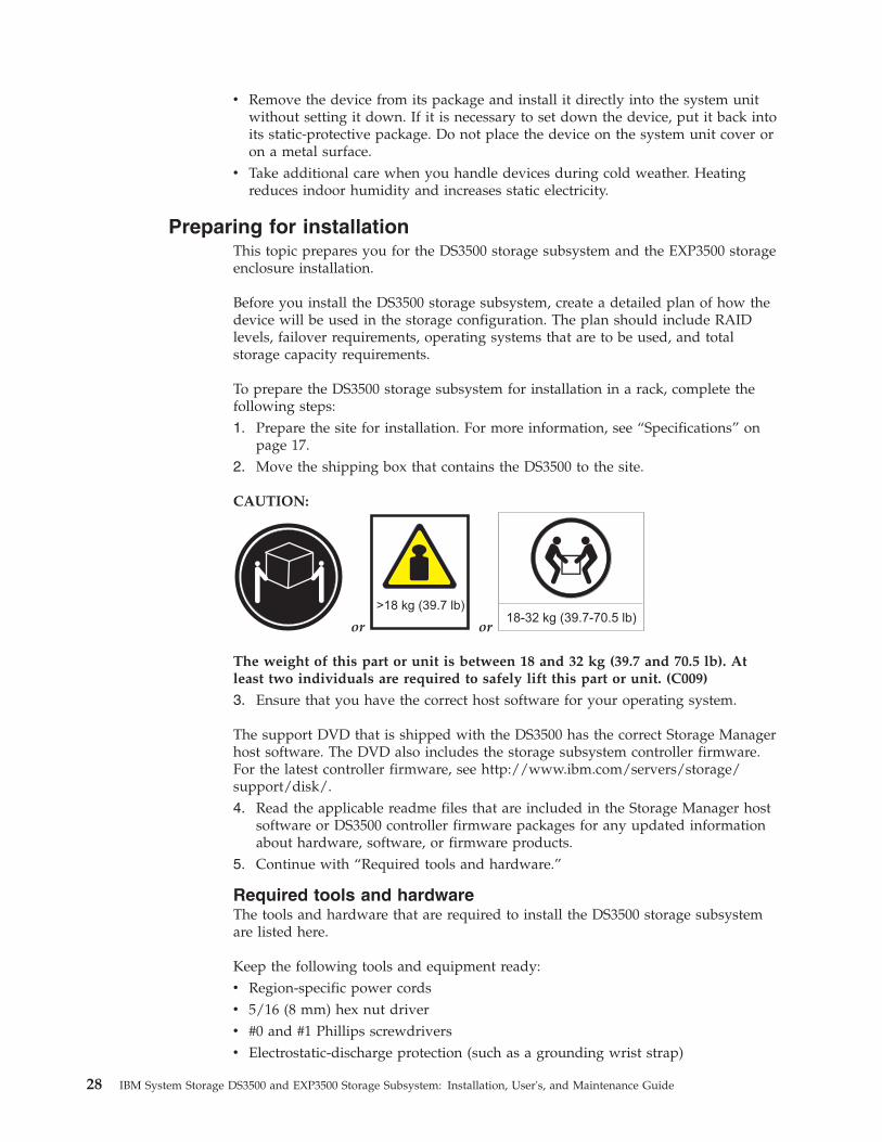
v Remove the device from its package and install it directly into the system unitwithout setting it down. If it is necessary to set down the device, put it back intoits static-protective package. Do not place the device on the system unit cover oron a metal surface.
v Take additional care when you handle devices during cold weather. Heatingreduces indoor humidity and increases static electricity.
Preparing for installationThis topic prepares you for the DS3500 storage subsystem and the EXP3500 storageenclosure installation.
Before you install the DS3500 storage subsystem, create a detailed plan of how thedevice will be used in the storage configuration. The plan should include RAIDlevels, failover requirements, operating systems that are to be used, and totalstorage capacity requirements.
To prepare the DS3500 storage subsystem for installation in a rack, complete thefollowing steps:1. Prepare the site for installation. For more information, see “Specifications” on
page 17.2. Move the shipping box that contains the DS3500 to the site.
CAUTION:
or
>18 kg (39.7 lb)
or18-32 kg (39.7-70.5 lb)
The weight of this part or unit is between 18 and 32 kg (39.7 and 70.5 lb). Atleast two individuals are required to safely lift this part or unit. (C009)
3. Ensure that you have the correct host software for your operating system.
The support DVD that is shipped with the DS3500 has the correct Storage Managerhost software. The DVD also includes the storage subsystem controller firmware.For the latest controller firmware, see http://www.ibm.com/servers/storage/support/disk/.4. Read the applicable readme files that are included in the Storage Manager host
software or DS3500 controller firmware packages for any updated informationabout hardware, software, or firmware products.
5. Continue with “Required tools and hardware.”
Required tools and hardwareThe tools and hardware that are required to install the DS3500 storage subsystemare listed here.
Keep the following tools and equipment ready:v Region-specific power cordsv 5/16 (8 mm) hex nut driverv #0 and #1 Phillips screwdriversv Electrostatic-discharge protection (such as a grounding wrist strap)
28 IBM System Storage DS3500 and EXP3500 Storage Subsystem: Installation, User's, and Maintenance Guide

v Rack power jumper cordsv Rack-mounting hardwarev Ethernet interface cables and cable straps (depending on configuration)v SAS cables (depending on configuration)v Fibre Channel cables, interface cables, and cable straps (depending on
configuration)v SFP modules (depending on configuration)
Preparing the siteThis section lists the floor space requirements and weight information for theDS3500. For information about interface cables and connections, see Chapter 3,“Cabling the storage subsystem and storage enclosure,” on page 31.
The floor area at the installation site must have:v Sufficient space to install the DS3500 storage subsystemv Enough stability to support the weight of the fully configured DS3500 storage
subsystem and associated devices (see “Weight” on page 18).
Ensure that all requirements, such as floor space, air conditioning, and electricalservice, are met. Other site preparation activities include:v Ensuring that there is enough room to move around the rack and install the
modules.v Installing uninterruptible-power-supply devices.v Installing, if applicable, host servers with host bus adapters (HBAs), switches, or
other devices.v Routing interface cables from the HBA ports in the hosts or switches to the
installation area.v Routing main power cords to the installation area.
Continue with “Installing the DS3500 storage subsystem in a rack.”
Installing the DS3500 storage subsystem in a rackTo install the DS3500 in a rack, follow the instructions in the DS3500 and EXP3500Rack Installation and Quick Start Guide. Then, continue with Chapter 3, “Cabling thestorage subsystem and storage enclosure,” on page 31.
Installing the EXP3500 storage enclosureThis section provides instructions for installing the EXP3500 storage enclosure in arack. The EXP3500 connects to a DS3500 storage subsystem.
Inventory checklistAfter you unpack the EXP3500 storage enclosure, ensure that you have thefollowing items. Depending on your order, the shipping box might containadditional materials that are not in the following list.v Hardware:
– Hard disk drives or drive filler panels:- EXP3512 (12)- EXP3524 (24)
– ESMs (up to 2)
Chapter 2. Installing the storage subsystem and storage enclosure 29

– Power supplies (2)– Power cables (2 jumper line cords)– Rack installation hardware kit:
- Support rails (2) (right and left assembly)- M5 black hex-head slotted screws (8)- M5 Washers (6)- Small diameter spacers (8) (these come installed, four in each rail)- Large diameter spacers (8)- M4 pan-head screws (2)
v Printed documents:
– IBM System Storage DS3500 and EXP3500 Rack Installation and Quick Start Guide
v Online documents:
– IBM System Storage DS3500 and EXP3500 Storage Subsystem Installation, User's,and Maintenance Guide (this document)
– IBM Systems Safety Notices
All documents are available on the IBM Documentation CD or from the IBMsupport Web site at http://www.ibm.com/servers/storage/support/.
Installing the EXP3500 storage enclosure in a rackYou can install the EXP3500 storage subsystem in an Electronic IndustriesAssociation (EIA) 310 standard rack. For complete rack installation instructions, seeIBM System Storage DS3500 and EXP3500 Rack Installation and Quick Start Guide.
30 IBM System Storage DS3500 and EXP3500 Storage Subsystem: Installation, User's, and Maintenance Guide

Chapter 3. Cabling the storage subsystem and storageenclosure
This section provides information and instructions for cabling the DS3500 storagesubsystem and the EXP3500 storage enclosure.
To cable the DS3500 storage subsystem, see “Cabling the DS3500 storagesubsystem.” To cable the EXP3500 storage enclosure, see “Cabling the EXP3500storage enclosure” on page 45.
Cabling the DS3500 storage subsystemThe section provides information and instructions for cabling the DS3500 storagesubsystem. After the storage subsystem is installed in its permanent location, youmust cable it to hosts, drives, and other external devices, depending on thehardware configuration.
Controller connectors (with Fibre Channel host port adapters)Figure 16 shows the optional Fibre Channel host port adapter installed in bothcontrollers on the rear panel of the DS3500 storage subsystem.
Fibre Channel host portsEach Fibre Channel host port supports a small-form-factor pluggable (SFP)transceiver and is capable of operating at 8 Gbps, 4 Gbps, or 2 Gbps.
Drive expansion portThe drive expansion port is an x4 multilane SAS port. Connect a SAS cableto this port and to a drive storage enclosure.
Controller connectors (with 1 Gbps iSCSI host port adapters)Figure 17 on page 32 shows the optional 1 Gbps iSCSI host port adapter installedin both controllers on the rear panel of the DS3500 storage subsystem.
Serial port
Ethernet ports
SAS host port 1
SAS host port 2 Fibre channel host port 3
Controller A
Fibre channel host port 4
Fibre channel host port 5
Fibre channel host port 6
Seven-segmentnumeric display
Controller B
dg1fy
065
Password Reset
Password Reset
Drive expansion port
Figure 16. Dual-controller DS3500 storage subsystem ports and controllers (with optionalFibre Channel host port adapter)
© Copyright IBM Corp. 2010, 2013 31

1 Gbps iSCSI host portsThe 1 Gbps iSCSI host ports are auto-negotiated 100/1000 Mbps Ethernetports that support iSCSI offload. The host ports also provide support forboth Internet Protocol version 4 (IPv4) and IPv6, and have the advancednetworking functions of jumbo frames, IEEE 802.1p, and virtual local areanetwork (VLAN) support.
Drive expansion portThe drive expansion port is an x4 multilane SAS port. Connect a SAS cableto this port and to a drive storage enclosure.
Controller connectors (with 10 Gbps iSCSI host port adapters)Figure 18 shows the optional 10 Gbps iSCSI host port adapter installed in bothcontrollers on the rear panel of the DS3500 storage subsystem.
10 Gbps iSCSI host portsThe 10 Gbps iSCSI host ports are auto-negotiated 1/10Gbps Ethernet portsthat support iSCSI offload. The host ports also provide support for both
Serial port
Ethernet ports
SAS host port 1
SAS host port 2 iSCSI host port 3
Controller A
Seven-segmentnumeric display
Controller B
dg1fy
070
Password Reset
Password Reset
Drive expansion port
iSCSI host port 4
iSCSI host port 5
iSCSI host port 6
Figure 17. Dual-controller DS3500 storage subsystem ports and controllers (with optionaliSCSI host port adapter)
e35i0
010
Controller A
Serial port
Ethernet ports
SAS host port 1
SAS host port 2 10 Gbps iSCSI port 3
10 Gbps iSCSI port 4
Drive expansion port
Controller B
Seven-segmentnumeric display
Powerconnector
Powerswitch
Powerconnector
Powerswitch
Passwordreset
Passwordreset
Figure 18. Dual-controller DS3500 storage subsystem ports and controllers (with optional 10iSCSI host port adapter)
32 IBM System Storage DS3500 and EXP3500 Storage Subsystem: Installation, User's, and Maintenance Guide
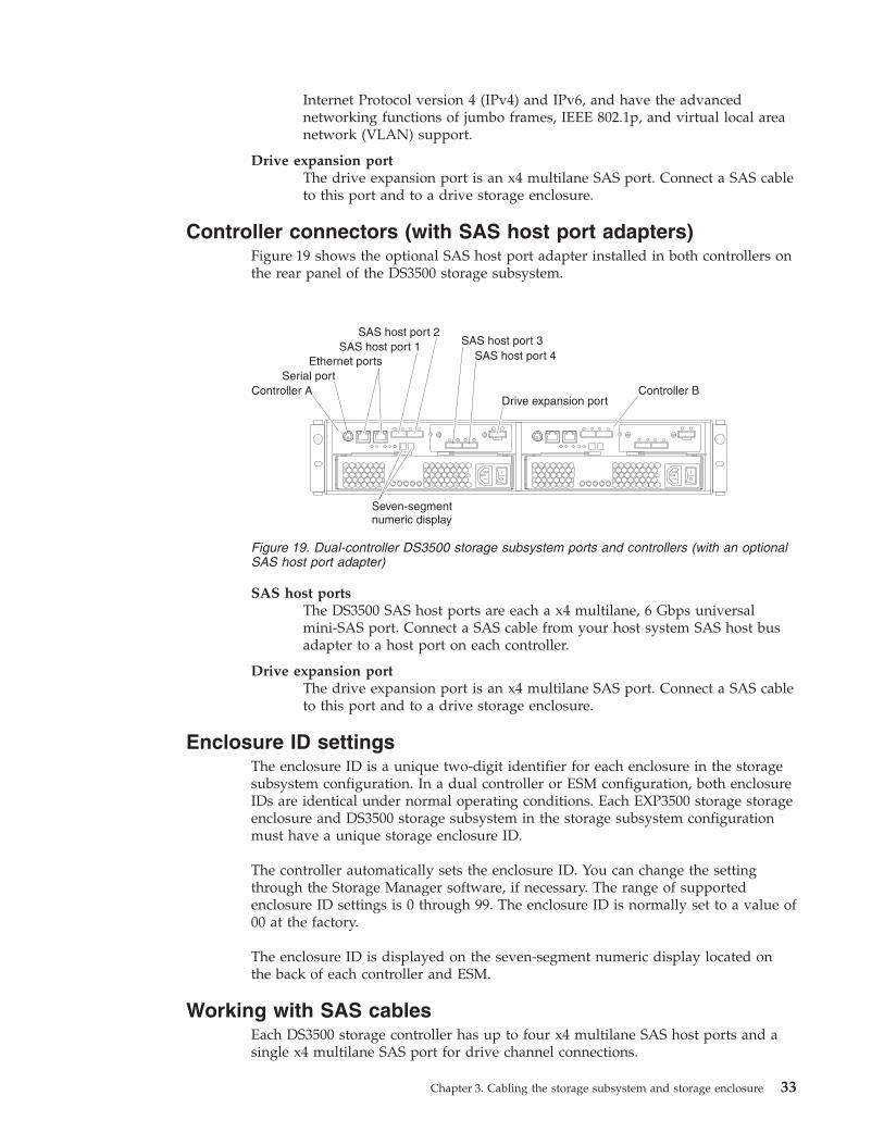
Internet Protocol version 4 (IPv4) and IPv6, and have the advancednetworking functions of jumbo frames, IEEE 802.1p, and virtual local areanetwork (VLAN) support.
Drive expansion portThe drive expansion port is an x4 multilane SAS port. Connect a SAS cableto this port and to a drive storage enclosure.
Controller connectors (with SAS host port adapters)Figure 19 shows the optional SAS host port adapter installed in both controllers onthe rear panel of the DS3500 storage subsystem.
SAS host portsThe DS3500 SAS host ports are each a x4 multilane, 6 Gbps universalmini-SAS port. Connect a SAS cable from your host system SAS host busadapter to a host port on each controller.
Drive expansion portThe drive expansion port is an x4 multilane SAS port. Connect a SAS cableto this port and to a drive storage enclosure.
Enclosure ID settingsThe enclosure ID is a unique two-digit identifier for each enclosure in the storagesubsystem configuration. In a dual controller or ESM configuration, both enclosureIDs are identical under normal operating conditions. Each EXP3500 storage storageenclosure and DS3500 storage subsystem in the storage subsystem configurationmust have a unique storage enclosure ID.
The controller automatically sets the enclosure ID. You can change the settingthrough the Storage Manager software, if necessary. The range of supportedenclosure ID settings is 0 through 99. The enclosure ID is normally set to a value of00 at the factory.
The enclosure ID is displayed on the seven-segment numeric display located onthe back of each controller and ESM.
Working with SAS cablesEach DS3500 storage controller has up to four x4 multilane SAS host ports and asingle x4 multilane SAS port for drive channel connections.
Serial portEthernet ports
SAS host port 1SAS host port 2
SAS host port 3
Controller A
SAS host port 4
Drive expansion port
Seven-segmentnumeric display
Controller B
Figure 19. Dual-controller DS3500 storage subsystem ports and controllers (with an optionalSAS host port adapter)
Chapter 3. Cabling the storage subsystem and storage enclosure 33
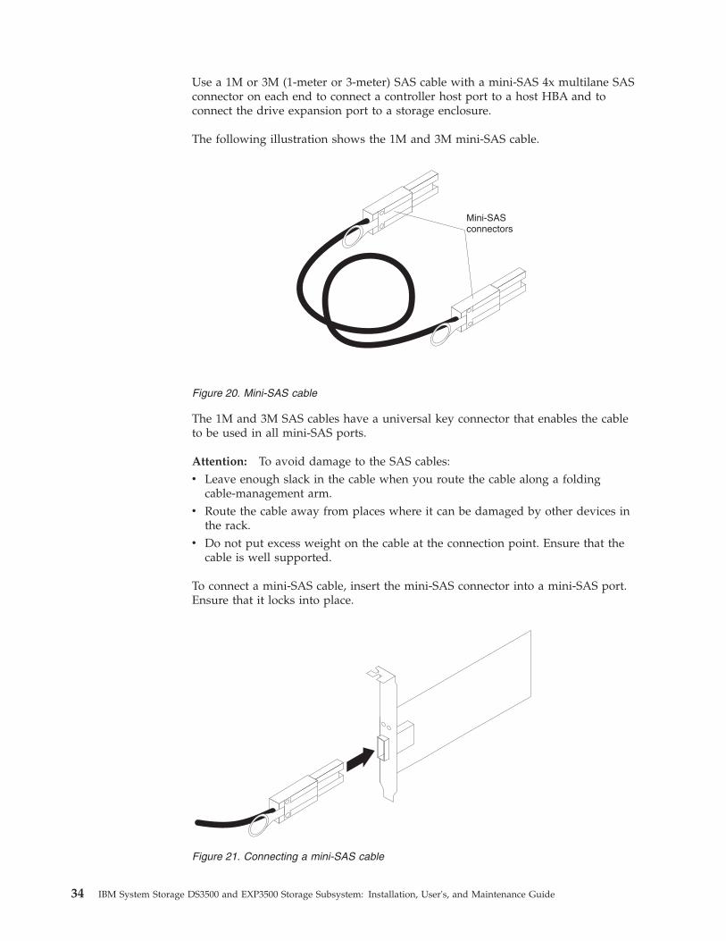
Use a 1M or 3M (1-meter or 3-meter) SAS cable with a mini-SAS 4x multilane SASconnector on each end to connect a controller host port to a host HBA and toconnect the drive expansion port to a storage enclosure.
The following illustration shows the 1M and 3M mini-SAS cable.
The 1M and 3M SAS cables have a universal key connector that enables the cableto be used in all mini-SAS ports.
Attention: To avoid damage to the SAS cables:v Leave enough slack in the cable when you route the cable along a folding
cable-management arm.v Route the cable away from places where it can be damaged by other devices in
the rack.v Do not put excess weight on the cable at the connection point. Ensure that the
cable is well supported.
To connect a mini-SAS cable, insert the mini-SAS connector into a mini-SAS port.Ensure that it locks into place.
Mini-SASconnectors
Figure 20. Mini-SAS cable
Figure 21. Connecting a mini-SAS cable
34 IBM System Storage DS3500 and EXP3500 Storage Subsystem: Installation, User's, and Maintenance Guide
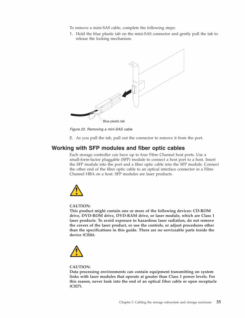
To remove a mini-SAS cable, complete the following steps:1. Hold the blue plastic tab on the mini-SAS connector and gently pull the tab to
release the locking mechanism.
2. As you pull the tab, pull out the connector to remove it from the port.
Working with SFP modules and fiber optic cablesEach storage controller can have up to four Fibre Channel host ports. Use asmall-form-factor pluggable (SFP) module to connect a host port to a host. Insertthe SFP module into the port and a fiber optic cable into the SFP module. Connectthe other end of the fiber optic cable to an optical interface connector in a FibreChannel HBA on a host. SFP modules are laser products.
CAUTION:This product might contain one or more of the following devices: CD-ROMdrive, DVD-ROM drive, DVD-RAM drive, or laser module, which are Class 1laser products. To avoid exposure to hazardous laser radiation, do not removethe covers of the laser product, or use the controls, or adjust procedures otherthan the specifications in this guide. There are no serviceable parts inside thedevice (C026).
CAUTION:Data processing environments can contain equipment transmitting on systemlinks with laser modules that operate at greater than Class 1 power levels. Forthis reason, never look into the end of an optical fiber cable or open receptacle(C027).
Blue plastic tab
Figure 22. Removing a mini-SAS cable
Chapter 3. Cabling the storage subsystem and storage enclosure 35

Handling fiber optic cablesAttention: To avoid damage to the fiber optic cables:v Do not route the cable along a folding cable-management arm.v For devices on slide rails, leave enough slack in the cables so that they do not
bend to a diameter of less than 76 mm (3 in), or a radius less than 38 mm (1.5in) when extended, or become pinched when retracted.
v Route the cable away from places where it can be damaged by other devices inthe rack cabinet.
v Do not use plastic cable ties instead of the provided cable straps.v Do not overtighten the cable straps or bend the cables to a diameter of less than
76 mm (3 in) or a radius less than 38 mm (1.5 in).v Do not put excess weight on the cable at the connection point. Ensure that the
cable is well supported.v The recommended maximum cable lengths are as follows:
– 2 Gbps: 300 m (984 ft.) of 50/125 um fiber, 150 m (492 ft.) of 62.5/125 umfiber
– 4 Gbps: 150 m (492 ft.) of 50/125 um fiber, 70 m (230 ft.) of 62.5/125 um fiber– 8 Gbps: 50 m (164 ft.) of 50/125 um fiber, 35 m (115 ft.) of 62.5/125 um fiber
v Recommended maximum lengths of OM2 category Fibre Channel cable are asfollows:– 4 Gbps: 150 m (492 ft.) of 50/125 um fiber, 300 m (984 ft.) of 62.5/125 um
fiber– 8 Gbps: 50 m (164 ft.) of 50/125 um fiber, 150 m (492 ft.) of 62.5/125 um fiber
Installing SFP modulesThe storage subsystem requires SFP modules. SFP modules convert electricalsignals to optical signals that are required for Fibre Channel transmission to andfrom controllers. After you install the SFP modules, you use fiber optic cables toconnect the storage subsystem to other Fibre Channel devices.
Review the following information before installing SFP modules and fiber opticcables:v Use only short-wave SFP modules. Do not mix long-wave and short-wave SFP
modules on a single storage subsystem. Use the Storage Manager Client to viewthe Storage Subsystem Profile to ensure that you are not mixing long-wave andshort-wave SFP modules.Attention: Do not use long-wave SFP modules or Gigabit Interface Converters(GBICs) in any of the Fibre Channel ports in the storage subsystem controllers.(Long-wave SFP modules and GBICs are not supported in the storage subsystemor any of the attached storage enclosures.
v The SFP module housing has an integral guide key that is designed to preventyou from inserting the SFP module incorrectly.
v Use minimal pressure when inserting an SFP module into a Fibre Channel port.Forcing the SFP module into a port could cause damage to the SFP module or tothe port.
v You can insert or remove the SFP module while the port is powered on.v The operational or redundant loop performance is not affected when you install
or remove an SFP module.v You must insert the SFP module into a port before you connect the fiber optic
cable.
36 IBM System Storage DS3500 and EXP3500 Storage Subsystem: Installation, User's, and Maintenance Guide
v You must remove the fiber optic cable from the SFP module before you removethe SFP module from the port. See “Removing SFP modules” on page 38 formore information.
v The speed of the SFP module determines the maximum operating speed of theFibre Channel port in which the SFP module is installed. For example, a 2-GbpsSFP module that is connected to a 4-Gbps-capable port will limit the speed ofthat port to a maximum of 2 Gbps.Attention: Check the IBM part number, option number, and FRU part numberof the SFP module to identify its speed. There are no physical features thatdistinguish an 8 Gbps, 4 Gbps, or 2 Gbps SFP module from each other.
CAUTION:This product might contain one or more of the following devices: CD-ROMdrive, DVD-ROM drive, DVD-RAM drive, or laser module, which are Class 1laser products. To avoid exposure to hazardous laser radiation, do not removethe covers of the laser product, or use the controls, or adjust procedures otherthan the specifications in this guide. There are no serviceable parts inside thedevice (C026).
CAUTION:Data processing environments can contain equipment transmitting on systemlinks with laser modules that operate at greater than Class 1 power levels. Forthis reason, never look into the end of an optical fiber cable or open receptacle(C027).
Attention: When you handle static-sensitive devices, take precautions to avoiddamage from static electricity. For details about handling static-sensitive devices,see “Handling static-sensitive devices” on page 27.
To install an SFP module, complete the following steps:1. Remove the SFP module from its static-protective package.2. Remove the protective cap from the SFP module, as shown in Figure 23 on
page 38. Save the protective cap for future use.
Chapter 3. Cabling the storage subsystem and storage enclosure 37
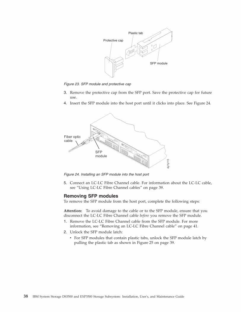
3. Remove the protective cap from the SFP port. Save the protective cap for futureuse.
4. Insert the SFP module into the host port until it clicks into place. See Figure 24.
5. Connect an LC-LC Fibre Channel cable. For information about the LC-LC cable,see “Using LC-LC Fibre Channel cables” on page 39.
Removing SFP modulesTo remove the SFP module from the host port, complete the following steps:
Attention: To avoid damage to the cable or to the SFP module, ensure that youdisconnect the LC-LC Fibre Channel cable before you remove the SFP module.1. Remove the LC-LC Fibre Channel cable from the SFP module. For more
information, see “Removing an LC-LC Fibre Channel cable” on page 41.2. Unlock the SFP module latch:
v For SFP modules that contain plastic tabs, unlock the SFP module latch bypulling the plastic tab as shown in Figure 25 on page 39.
Protective cap
SFP module
Plastic tab
Figure 23. SFP module and protective cap
SFPmodule
Fiber opticcable
dg1fy
115
Figure 24. Installing an SFP module into the host port
38 IBM System Storage DS3500 and EXP3500 Storage Subsystem: Installation, User's, and Maintenance Guide

v For SFP modules that contain wire tabs, unlock the SFP module latch bypulling the wire latch as shown in Figure 26.
3. With the SFP module latch in the unlocked position, remove the SFP module.v For SFP modules that contain plastic tabs, slide the SFP module out of the
port.v For SFP modules that contain wire tabs, grasp the wire latch and pull the
SFP module out of the port.4. Replace the protective cap on the SFP module.5. Place the SFP module into a static-protective package.6. Replace the protective cap on the host port.
Using LC-LC Fibre Channel cablesThe LC-LC Fibre Channel cable is a fibre optic cable that you use to connect FibreChannel ports to one of the following devices:v An SFP module installed in a Fibre Channel switch portv A Fibre Channel host bus adapter port (optical interface connector)
See Figure 27 on page 40 for an illustration of the LC-LC Fibre Channel cable.
For more information, see the documentation that was shipped with the LC-LCFibre Channel cable.
Protective cap
SFP module
10
Plastic tab
Figure 25. Unlocking the SFP module latch - plastic variety
Protectivecap
SFPmodule
90
Wiretab
Figure 26. Unlocking the SFP module latch - wire variety
Chapter 3. Cabling the storage subsystem and storage enclosure 39

Connecting an LC-LC cable to an SFP module:To connect an LC-LC Fibre Channel cable to an SFP module, complete thefollowing steps.
CAUTION:This product might contain one or more of the following devices: CD-ROMdrive, DVD-ROM drive, DVD-RAM drive, or laser module, which are Class 1laser products. To avoid exposure to hazardous laser radiation, do not removethe covers of the laser product, or use the controls, or adjust procedures otherthan the specifications in this guide. There are no serviceable parts inside thedevice (C026).
CAUTION:Data processing environments can contain equipment transmitting on systemlinks with laser modules that operate at greater than Class 1 power levels. Forthis reason, never look into the end of an optical fiber cable or open receptacle(C027).
1. Read the information in “Handling fiber optic cables” on page 36.2. If necessary, remove the protective cap from the SFP module, as shown in
Figure 23 on page 38. Save the protective cap for future use.3. Remove the two protective caps from one end of the LC-LC cable, as shown in
Figure 28 on page 41. Save the protective caps for future use.
Figure 27. LC-LC Fibre Channel cable
40 IBM System Storage DS3500 and EXP3500 Storage Subsystem: Installation, User's, and Maintenance Guide

4. Carefully insert the open end of the LC-LC cable into an SFP module that isinstalled in the storage subsystem. The cable connector is keyed for correctinstallation. Holding the connector, push in the cable until it clicks into place,as shown in Figure 29.
5. Remove the two protective caps from the other end of the LC-LC cable. Savethe protective caps for future use.
6. Connect this end of the LC-LC cable to one of the following devices:v An SFP module that is installed in a Fibre Channel switch portv A Fibre Channel host bus adapter port
Removing an LC-LC Fibre Channel cable:To remove an LC-LC Fibre Channel cable, complete the following steps.
Attention: To avoid damaging the LC-LC cable or SFP module, ensure that youobserve the following precautions:v Press and hold the lever to release the latches before you remove the cable from
the SFP module.v Ensure that the levers are in the released position when you remove the cable.v Do NOT grasp the SFP module plastic tab when you remove the cable.1. At the end of the LC-LC cable that connects into the SFP module or host bus
adapter, press down and hold the lever to release the latches, as shown in
Protective cap
Fiber-opticcable
Figure 28. Removing fiber optic cable protective caps
Figure 29. Inserting an LC-LC Fibre Channel cable into an SFP module
Chapter 3. Cabling the storage subsystem and storage enclosure 41
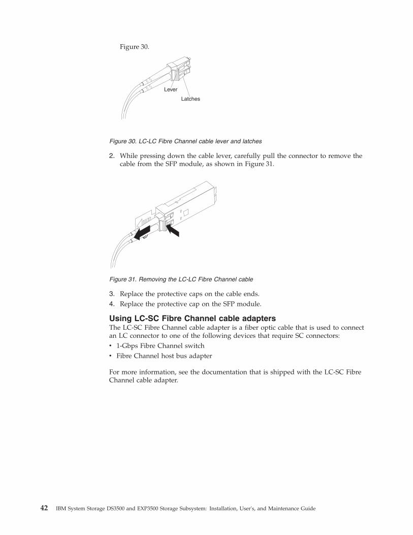
Figure 30.
Lever
Latches
2. While pressing down the cable lever, carefully pull the connector to remove thecable from the SFP module, as shown in Figure 31.
3. Replace the protective caps on the cable ends.4. Replace the protective cap on the SFP module.
Using LC-SC Fibre Channel cable adaptersThe LC-SC Fibre Channel cable adapter is a fiber optic cable that is used to connectan LC connector to one of the following devices that require SC connectors:v 1-Gbps Fibre Channel switchv Fibre Channel host bus adapter
For more information, see the documentation that is shipped with the LC-SC FibreChannel cable adapter.
Figure 30. LC-LC Fibre Channel cable lever and latches
Figure 31. Removing the LC-LC Fibre Channel cable
42 IBM System Storage DS3500 and EXP3500 Storage Subsystem: Installation, User's, and Maintenance Guide

The following sections include the procedures for correctly connecting andremoving an LC-SC Fibre Channel cable.
CAUTION:This product might contain one or more of the following devices: CD-ROMdrive, DVD-ROM drive, DVD-RAM drive, or laser module, which are Class 1laser products. To avoid exposure to hazardous laser radiation, do not removethe covers of the laser product, or use the controls, or adjust procedures otherthan the specifications in this guide. There are no serviceable parts inside thedevice (C026).
CAUTION:Data processing environments can contain equipment transmitting on systemlinks with laser modules that operate at greater than Class 1 power levels. Forthis reason, never look into the end of an optical fibre cable or open receptacle(C027).
Connecting an LC-SC cable adapter to a device:To connect an LC-SC Fibre Channel cable adapter to a device, complete thefollowing steps:1. Read the information in “Handling fiber optic cables” on page 36.2. Connect one end of an LC-LC cable to an SFP module in the DS3500. For
instructions, see “Using LC-LC Fibre Channel cables” on page 39.3. Remove the two protective caps from the LC connector end of the LC-SC cable
adapter as shown in Figure 33 on page 44. Save the protective caps for futureuse.
LC connector
SC connector
Figure 32. LC-SC Fibre Channel cable adapter
Chapter 3. Cabling the storage subsystem and storage enclosure 43

4. Carefully insert the other end of the LC-LC cable into the LC connector end ofthe LC-SC cable adapter as shown in Figure 34. Push in the connector until itclicks into place.
5. If you are connecting the storage subsystem to a 1-Gbps Fibre Channel switchor Fibre Channel host bus adapter, connect the SC connector end of the LC-SCcable adapter to a Gigabit Interface Converter (GBIC) that is installed in the1-Gbps Fibre Channel switch or Fibre Channel host bus adapter. For moreinformation about connecting to these devices, see the documentation that isshipped with the device.
Removing an LC-LC cable from an LC-SC cable adapter:To remove an LC-LC cable from an LC-SC cable adapter, complete the followingsteps.
Attention: To avoid damaging the LC-LC cable, ensure that you press and holdthe lever to release the latches before you remove the cable from an LC-SC cableadapter. When removing the cable from the SFP module, ensure that you do notgrasp the SFP module plastic tab.1. At the end of the cable that connects into the LC connector end of the LC-SC
cable adapter, press down and hold the lever to release the latches. Figure 35 onpage 45 shows the location of the lever and latches.
Figure 33. Removing the LC-SC cable adapter protective caps
Figure 34. Connecting an LC-LC cable into the LC-SC cable adapter
44 IBM System Storage DS3500 and EXP3500 Storage Subsystem: Installation, User's, and Maintenance Guide

2. Carefully pull the connector to remove it. Ensure that you grasp the connectorand not the cable when removing the LC-LC cable from the LC-SC cableadapter as shown in Figure 36.
3. Replace the protective caps on the cable ends.
Cabling the EXP3500 storage enclosureThe EXP3500 storage enclosure contains an ESM that enables you to connect theEXP3500 storage enclosure to a DS3500 storage subsystem. If you are attaching theEXP3500 to a dual controller DS3500 storage subsystem, you must add a secondESM to the EXP3500 storage enclosure to provide a redundant drive path.
ESM connectorsFigure 37 shows the connectors on the ESM.
SAS In 1Connect a SAS cable to this connector and to either an IBM SAS controlleror the SAS Out (↓) connector of another EXP3500.
Lever
Latches
Figure 35. LC-LC Fibre Channel cable lever and latches
Figure 36. Removing the LC-LC Fibre Channel cable from an LC-SC Fibre Channel cableadapter
1 2
ESM
SAS in connector 1 SAS in connector 2 SAS out connector
Figure 37. ESM connectors
Chapter 3. Cabling the storage subsystem and storage enclosure 45

SAS In 2Connect a SAS cable to this connector and to either an IBM SAS controlleror the SAS Out (↓) connector of another EXP3500.
SAS OutConnect a SAS cable to this connector and to the SAS In (↑) connector ofanother EXP3500.
Note: Each ESM contains two SAS In connectors. You can use either SAS Inconnector, but only one SAS In connector can be used at a time.
Single-ESM configurationThe DS3500 storage controller supports more than one EXP3500 storage enclosureper drive expansion port. You can connect two or more EXP3500 storage enclosuresby chaining them together. To connect a controller to one or more EXP3500 storageenclosures that have one ESM each, complete the following steps:1. Connect one EXP3500 storage enclosure to the controller:
a. Connect one end of a SAS cable to the drive expansion port on thecontroller.
b. Connect the other end to one of the In (↑) SAS connectors on the ESM inthe EXP3500 storage enclosure.
2. Connect a second EXP3500 storage enclosure to the first EXP3500 storageenclosure:a. Connect one end of a SAS cable to the Out (↓) SAS connector on the ESM of
the EXP3500 storage enclosure that you just connected.b. Connect the other end of the SAS cable to one of the In (↑) SAS connectors
on the ESM on the next EXP3500 storage enclosure.c. Repeat steps 2a and 2b for each EXP3500 storage enclosure that you add.
Dual-ESM configurationThe EXP3500 storage enclosure comes with one ESM. If your DS3500 storagesubsystem is a dual controller configuration, it supports redundant drive paths.You must install a second ESM. See “Installing an additional ESM” on page 157before attaching any EXP3500 storage enclosures.
Dual-ESM configuration with a single EXP3500 storage enclosure:
46 IBM System Storage DS3500 and EXP3500 Storage Subsystem: Installation, User's, and Maintenance Guide

To connect controllers A and B to one EXP3500 storage enclosure that has twoESMs, complete the following steps:1. Connect the EXP3500 storage enclosure to controller A:
a. Connect one end of a SAS cable to controller A.b. Connect the other end of the SAS cable to one of the In (↑) SAS connectors
on the left ESM in the EXP3500 storage enclosure.2. Connect the EXP3500 storage enclosure to controller B:
a. Connect one end of a SAS cable to controller B.b. Connect the other end of the SAS cable to one of the In (↑) SAS connectors
on the right ESM in the EXP3500 storage enclosure.
Dual-ESM configuration with two or more EXP3500 storage enclosures:The DS3500 controllers support more than one EXP3500 storage enclosure perphysical port, so multiple EXP3500 storage enclosures can be connected bychaining them together.
To connect DS3500 controllers A and B to multiple EXP3500 storage enclosures thathave two ESMs each, complete the following steps:1. Connect one EXP3500 storage enclosure to controller A:
a. Connect one end of a SAS cable to the drive expansion port on the DS3500controller A.
Chapter 3. Cabling the storage subsystem and storage enclosure 47

b. Connect the other end of the SAS cable to one of the In (↑) SAS connectorson the left ESM in the EXP3500 storage enclosure.
2. Connect the left ESM of the EXP3500 storage enclosure to the next EXP3500storage enclosure in the chain:a. Connect one end of a SAS cable to the Out (↓) SAS connector on the left
ESM of the EXP3500 storage enclosure that you just connected.b. Connect the other end of the SAS cable to one of the In (↑) SAS connectors
on the left ESM in the next EXP3500 storage enclosure in the chain.c. Repeat steps 2a and 2b for each EXP3500 storage enclosure that you add.
3. Connect the last EXP3500 storage enclosure in the chain to controller B:a. Connect one end of a SAS cable to the drive expansion port on the DS3500
controller B.b. Connect the other end of the SAS cable to one of the In (↑) SAS connectors
on the right ESM in the last EXP3500 storage enclosure of the chain thatyou created.
4. In reverse order (last in chain to first in chain), connect the right ESMs in theEXP3500 storage enclosures in the chain:a. Connect one end of a SAS cable to the Out (↓) SAS connector on the right
ESM of the EXP3500 storage enclosure that you just connected.b. Connect the other end of the SAS cable to one of the In (↑) SAS connectors
on the right ESM of the previous EXP3500 storage enclosure in the chain.c. Repeat steps 2a and 2b until you connect the right ESM of the first EXP3500
storage enclosure in step 2 to the right ESM of the EXP3500 storageenclosure in step 1 on page 47.
Connecting storage enclosures to the DS3500The DS3500 supports either the EXP3512 or the EXP3524 storage enclosure. TheDS3500 supports up to 192 drives (with controller firmware 7.77.xx.xx and later) or96 drives (with controller firmware 7.75.xx.xx and earlier).
The total number of storage enclosures supported varies depending on the modelof DS3500 storage subsystem and EXP3500 storage enclosure. See the followingtables Table 11 and Table 12 on page 49.
Table 11 shows the maximum number of EXP3512 and EXP3524 storage enclosuresthat can be attached to either a DS3512 or a DS3524 storage subsystem, and notexceed 192 total disk drives with controller firmware level 7.77.xx.xx and later. Anycombination of EXP3512 or EXP3524 storage enclosures can be attached to aDS3512 or a DS3524 as long as the total number of disk drives does not exceed192.
Table 11. Maximum number of EXP3512 and EXP3524 storage enclosures with controllerfirmware level 7.77.xx.xx and later
DS3512 DS3524
Storageenclosures
Quantity Storageenclosures
Quantity
EXP3512 15 14 13 12 EXP3524 7 6 5 4
EXP3524 0 0 1 1 EXP3512 0 2 5 6
or or
48 IBM System Storage DS3500 and EXP3500 Storage Subsystem: Installation, User's, and Maintenance Guide

Table 11. Maximum number of EXP3512 and EXP3524 storage enclosures with controllerfirmware level 7.77.xx.xx and later (continued)
DS3512 DS3524
EXP3512 11 10 9 8 EXP3524 3 2 1
EXP3524 2 2 3 3 EXP3512 8 10 12
or
EXP3512 7 6 5 4
EXP3524 4 4 5 5
or
EXP3512 3 2 1
EXP3524 6 6 7
Table 12 shows the maximum number of EXP3512 and EXP3524 storage enclosuresthat can be attached to either a DS3512 or a DS3524 storage subsystem and notexceed the 96 total disk drives with controller firmware level 7.75.xx.xx and earlier.Any combination of EXP3512 or EXP3524 storage enclosures can be attached to aDS3512 or a DS3524 as long as the total number of disk drives does not exceed 96.
Table 12. Maximum number of EXP3512 and EXP3524 storage enclosures with controllerfirmware level 7.75.xx.xx and earlier
DS3512 DS3524
Storageenclosures
Quantity Storageenclosures
Quantity
EXP3512 7 5 3 1 EXP3524 3 2 1 0
EXP3524 0 1 2 3 EXP3512 0 2 4 6
Redundant drive channel pairEach storage controller on the DS3500 has a drive expansion channel that containsan x4 SAS port. The storage enclosures that are connected to this connector form adrive channel. You can install a maximum of 96 drives in one drive channel. In adual-controller DS3500, one drive channel from each controller combines to form aredundant drive-channel pair.
Figure 38 on page 50 shows an example of a redundant drive-channel pair. If anycomponent of the drive channel fails, the controllers can still access the storageenclosures in the redundant drive-channel pair.
Note: In storage enclosures that are connected to a dual-controller storagesubsystem, you must install the optional second ESM to support dual redundantdrive paths.
Chapter 3. Cabling the storage subsystem and storage enclosure 49

Connecting storage enclosures to a storage subsystemTo connect storage enclosures to the storage subsystem, complete the followingsteps:1. Follow the instructions in the IBM System Storage DS3500 and EXP3500 Rack
Installation and Quick Start Guide for the storage enclosure and the rackinstallation instructions to set up and mount the storage enclosures.
2. Select a cabling topology applicable to the number of ESMs in the storageenclosures that you will connect to the DS3500. “DS3500 storage subsystemdrive cabling topologies” describes the recommended schemes for cablingstorage enclosures with one ESM or two ESMs to the DS3500 and to each other(if you are connecting more than one storage enclosure).
3. Follow the cabling diagram for the selected topology.4. If required, set unique enclosure IDs for all storage enclosures that are cabled to
the DS3500. For information about setting the enclosure ID, see the IBM SystemStorage DS Storage Manager Version 10 Installation and Host Support Guide (for DSStorage Manager V10.77 or earlier) and IBM System Storage DS Storage ManagerVersion 10.8 Installation and Host Support Guide (for DS Storage Manager V10.83or later).
The DS3500 storage subsystem locates the drives in the storage enclosures afteryou power-on the configuration. Always turn on the storage enclosures first andthen turn on the DS3500. After you have powered-on the configuration, use theStorage Manager software to check the status of the new drives, correct any errors,and configure the new drives.
DS3500 storage subsystem drive cabling topologiesThis section contains the preferred cabling topologies for cabling storage enclosuresto the DS3500 storage subsystem:
Figure 38. Example of a redundant drive path
50 IBM System Storage DS3500 and EXP3500 Storage Subsystem: Installation, User's, and Maintenance Guide

v “One single-controller DS3500 and one or more storage enclosures”v “One dual-controller DS3500 and one storage enclosure”v “One dual-controller DS3500 and two storage enclosures” on page 52v “One dual-controller DS3500 and up to eight storage enclosures” on page 52
If one of these topologies is suitable for the hardware and application in yourbusiness setup, complete the cabling connections as shown in the illustrations. Ifyou have a setup other than the ones shown in these examples, use these examplesas a starting point for creating your specific topology.
Note: In storage enclosures that are connected to a dual-controller storagesubsystem, you must install the optional second ESM to support dual redundantdrive paths.
One single-controller DS3500 and one or more storage enclosures:To cable one single-controller DS3500 to one or more single-ESM storageenclosures, connect them as shown in Figure 39.
Note: In storage enclosures that are connected to a dual-controller storagesubsystem, you must install the optional second ESM to support dual redundantdrive paths, and must use one of the dual-controller topologies that are describedin this section.
One dual-controller DS3500 and one storage enclosure:To cable a dual-controller DS3500 to a storage enclosure, connect them as shown inFigure 40 on page 52.
Figure 39. One single-controller DS3500 and multiple single-ESM storage enclosures
Chapter 3. Cabling the storage subsystem and storage enclosure 51

One dual-controller DS3500 and two storage enclosures:To cable a dual-controller DS3500 and two storage enclosures, connect them asshown in Figure 41.
One dual-controller DS3500 and up to eight storage enclosures:To cable a dual-controller DS3500 and up to eight storage enclosures, connect themas shown in Figure 42 on page 53.
Figure 40. A dual-controller DS3500 and a storage enclosure
Figure 41. A dual-controller DS3500 and two storage enclosures
52 IBM System Storage DS3500 and EXP3500 Storage Subsystem: Installation, User's, and Maintenance Guide

Adding a storage enclosure to a running dual-controllerconfigurationComplete the following steps to add storage enclosures to a runningdual-controller DS3500 storage subsystem.
Note: Ensure that each storage enclosure has two ESMs before you connect it to adual-controller DS3500 storage subsystem. The second ESM must be purchasedseparately. Contact your IBM marketing representative or authorized reseller formore information about purchasing a second ESM. For more information aboutinstalling a second ESM, see the Installation Guide that is shipped with the storageenclosure.1. Ensure that the DS3500 storage subsystem status is Optimal in the Storage
Manager software.
Figure 42. A dual-controller DS3500 and eight storage enclosures
Chapter 3. Cabling the storage subsystem and storage enclosure 53

2. Use the storage enclosure Rack Installation Instructions document to installthe new storage enclosure in the rack.
3. Connect the power cables to the new storage enclosure.4. Power on the storage enclosure.5. Connect one end of a Serial Attached SCSI (SAS) cable to the Drive expansion
port on Controller A in the DS3500 storage subsystem.6. Connect the other end of the SAS cable to either of the In ports on the left
ESM in the storage enclosure.7. Connect one end of a second SAS cable to the Drive expansion port on
Controller B in the DS3500 storage subsystem.8. Connect the other end of the second SAS cable to the In port on the right ESM
in the storage enclosure.9. Wait until the storage subsystem status is Optimal in the Storage Manager
software before proceeding to step 10.10. Add the drives to the storage enclosure. Ensure that you wait for at least 30
seconds for the Storage Manager software to recognize each newly addeddrive before you install another drive.To add additional storage enclosures after the first storage enclosure isconnected to a dual-controller DS3500 storage subsystem, complete thefollowing steps:a. Ensure that the storage subsystem status is Optimal in the Storage
Manager software.b. Use the storage enclosure Rack Installation Instructions document to install
the new storage enclosure in the rack.c. Connect the power cables to the new storage enclosure.d. Power on the storage enclosure.e. Connect one end of a Serial Attached SCSI (SAS) cable to the In port on
the left ESM in the storage enclosure that is being added to theconfiguration.
f. Connect the other end of the SAS cable to the Out port on the left ESM inthe last storage enclosure in the configuration (this storage enclosure isdirectly connected to the Drive expansion port on controller A of theDS3500).
Note: The above step is true only for the configuration of the EXP3500storage subsystem expansion unit. For DS3500 storage subsystemdual-controller connections go to the next step.
g. On the last storage enclosure in the configuration, disconnect the SAScable from the In port on the right ESM and connect it to the In port onthe right ESM on the new storage enclosure that is being added to theconfiguration.
Note: When the SAS cable is disconnected in step 7, a loss of pathredundancy occurs and an error message is displayed in the StorageManager Recovery Guru. Ignore this error message. The redundant path isrestored in step h after the SAS cable is connected.
h. Connect a SAS cable to the Out port on the right ESM of the new storageenclosure and connect the other end to either of the In port on the rightESM in the storage enclosure that was previously connected to controller Bof the DS3500.
54 IBM System Storage DS3500 and EXP3500 Storage Subsystem: Installation, User's, and Maintenance Guide

i. Wait until the storage subsystem status is Optimal in the Storage Managersoftware before proceeding to step 10.
j. Add the drives to the storage enclosure. Make sure that you wait for atleast 30 seconds for the Storage Manager software to recognize each newlyadded drive before you install another drive.
Upgrading a single-controller to a dual-controller when thereis no attached EXP3500 enclosure
If you are upgrading a single-controller DS3500 storage subsystem to adual-controller DS3500 storage subsystem and there are no EXP3500 storageenclosures attached to the DS3500 storage subsystem, see “Installing a controller”on page 107.
Upgrading a single-controller to a dual-controller when thereis one or more EXP3500 enclosures attached to the storagesubsystem
Before you upgrade the DS3500 storage subsystem from a single-controller to adual-controller, ensure that you purchase:v a second environmental services module (ESM) for each EXP3500 storage
enclosure that is attached to the DS3500 storage subsystem. You will install thesecond ESM during this procedure.
v the SAS cables that are required to create a redundant drive enclosure path.
To upgrade a single-controller DS3500 storage subsystem to a dual-controllerDS3500 storage subsystem when there are EXP3500 storage enclosures attached tothe DS3500, complete the following steps:1. Turn off the DS3500 storage subsystem and all attached EXP3500 storage
enclosures.2. Install a second controller in the DS3500 storage subsystem by using the
instructions in “Installing a controller” on page 107.3. Install a second ESM in each EXP3500 that is connected to the DS3500 storage
subsystem:a. Read the safety information on page “Safety” on page ix and “Best practices
guidelines” on page 8.b. Remove the ESM filler panel from the rightmost ESM bay of the EXP3500.
On the left side of the ESM filler panel, press the orange release tab to theright just enough to release the handle (no more than 6 mm [0.25 in.]) asyou turn the handle upward. Using the handle, gently slide the ESM fillerpanel out of the EXP3500. Save the ESM filler panel for future use.
c. Hold the new ESM so that the handle is fully extended.d. Gently slide the ESM into the bay until it stops. Turn the handle downward
into the closed position until it clicks.4. For dual-controller models, connect SAS cables to create a redundant
drive-channel path from the DS3500 controllers to the EXP3500 ESMs using theinformation provided in “DS3500 storage subsystem drive cabling topologies”on page 50,
Connecting secondary interface cablesThis section applies to direct (out-of-band) management configurations only. Ifyour configuration uses host-agent (in-band) management, skip this section.
Chapter 3. Cabling the storage subsystem and storage enclosure 55
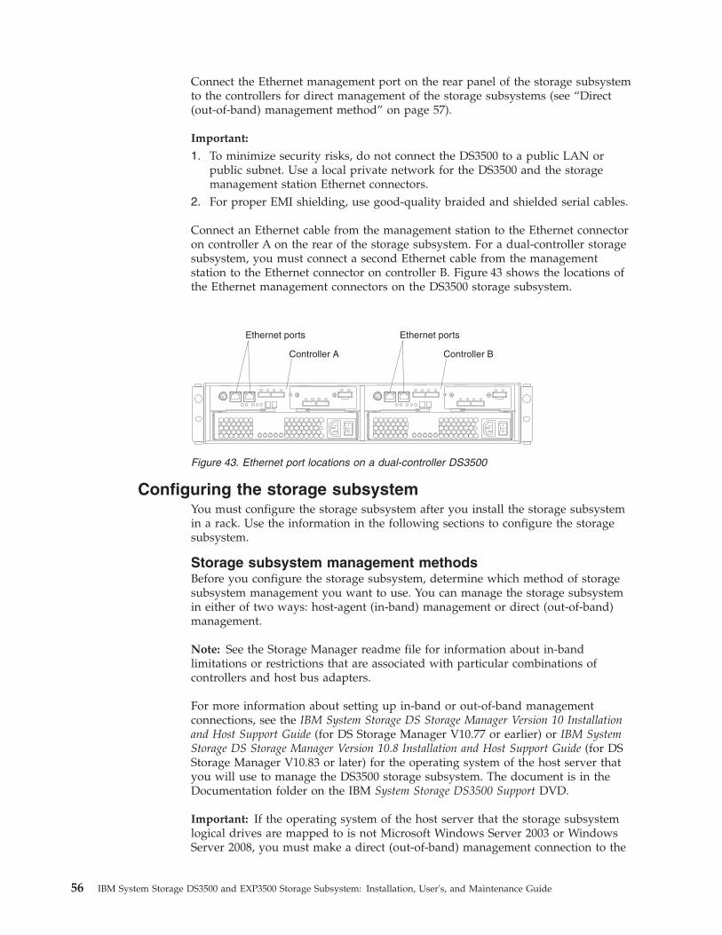
Connect the Ethernet management port on the rear panel of the storage subsystemto the controllers for direct management of the storage subsystems (see “Direct(out-of-band) management method” on page 57).
Important:
1. To minimize security risks, do not connect the DS3500 to a public LAN orpublic subnet. Use a local private network for the DS3500 and the storagemanagement station Ethernet connectors.
2. For proper EMI shielding, use good-quality braided and shielded serial cables.
Connect an Ethernet cable from the management station to the Ethernet connectoron controller A on the rear of the storage subsystem. For a dual-controller storagesubsystem, you must connect a second Ethernet cable from the managementstation to the Ethernet connector on controller B. Figure 43 shows the locations ofthe Ethernet management connectors on the DS3500 storage subsystem.
Configuring the storage subsystemYou must configure the storage subsystem after you install the storage subsystemin a rack. Use the information in the following sections to configure the storagesubsystem.
Storage subsystem management methodsBefore you configure the storage subsystem, determine which method of storagesubsystem management you want to use. You can manage the storage subsystemin either of two ways: host-agent (in-band) management or direct (out-of-band)management.
Note: See the Storage Manager readme file for information about in-bandlimitations or restrictions that are associated with particular combinations ofcontrollers and host bus adapters.
For more information about setting up in-band or out-of-band managementconnections, see the IBM System Storage DS Storage Manager Version 10 Installationand Host Support Guide (for DS Storage Manager V10.77 or earlier) or IBM SystemStorage DS Storage Manager Version 10.8 Installation and Host Support Guide (for DSStorage Manager V10.83 or later) for the operating system of the host server thatyou will use to manage the DS3500 storage subsystem. The document is in theDocumentation folder on the IBM System Storage DS3500 Support DVD.
Important: If the operating system of the host server that the storage subsystemlogical drives are mapped to is not Microsoft Windows Server 2003 or WindowsServer 2008, you must make a direct (out-of-band) management connection to the
Ethernet ports
Controller A
Ethernet ports
Controller B
Figure 43. Ethernet port locations on a dual-controller DS3500
56 IBM System Storage DS3500 and EXP3500 Storage Subsystem: Installation, User's, and Maintenance Guide
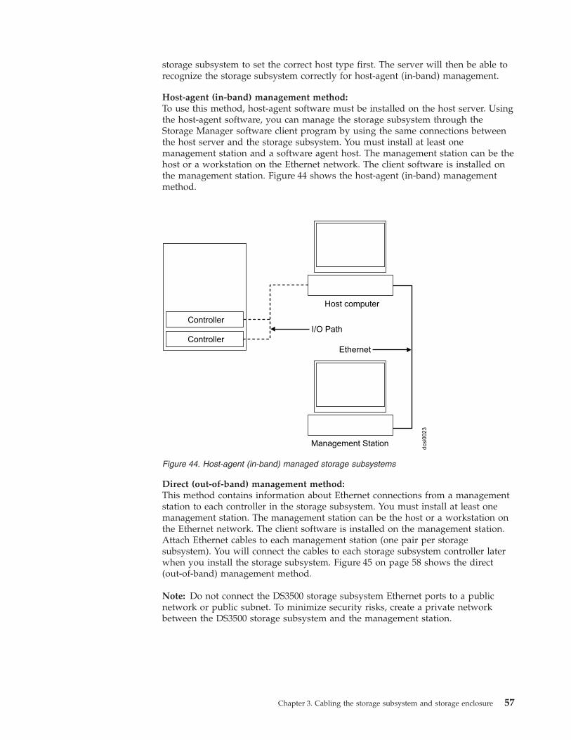
storage subsystem to set the correct host type first. The server will then be able torecognize the storage subsystem correctly for host-agent (in-band) management.
Host-agent (in-band) management method:To use this method, host-agent software must be installed on the host server. Usingthe host-agent software, you can manage the storage subsystem through theStorage Manager software client program by using the same connections betweenthe host server and the storage subsystem. You must install at least onemanagement station and a software agent host. The management station can be thehost or a workstation on the Ethernet network. The client software is installed onthe management station. Figure 44 shows the host-agent (in-band) managementmethod.
Direct (out-of-band) management method:This method contains information about Ethernet connections from a managementstation to each controller in the storage subsystem. You must install at least onemanagement station. The management station can be the host or a workstation onthe Ethernet network. The client software is installed on the management station.Attach Ethernet cables to each management station (one pair per storagesubsystem). You will connect the cables to each storage subsystem controller laterwhen you install the storage subsystem. Figure 45 on page 58 shows the direct(out-of-band) management method.
Note: Do not connect the DS3500 storage subsystem Ethernet ports to a publicnetwork or public subnet. To minimize security risks, create a private networkbetween the DS3500 storage subsystem and the management station.
dcsi0
023
Controller
Controller
Host computer
Management Station
I/O Path
Ethernet
Figure 44. Host-agent (in-band) managed storage subsystems
Chapter 3. Cabling the storage subsystem and storage enclosure 57

Installing the storage subsystem configurationBefore attempting to attach hosts to the storage subsystem, ensure that the hostsystems and host bus adapters (HBAs) are installed correctly and updated with thelatest firmware and drivers.
Note: Use the correct HBA firmware and device driver. For the latest supportedHBAs and device drivers, consult the readme that is shipped with the DS3500controller firmware. See the documentation that is shipped with the HBA forinstallation requirements and procedures.
For a SAS attached host, attach a SAS cable to each HBA. Continue with“Connecting SAS hosts to the DS3500” on page 59 to connect the other end of eachcable to a controller.
Figure 45. Direct (out-of-band) managed storage subsystems
58 IBM System Storage DS3500 and EXP3500 Storage Subsystem: Installation, User's, and Maintenance Guide

For a Fibre Channel attached host, attach a fibre channel cable to each HBA.Continue with “Connecting Fibre Channel hosts to the DS3500” on page 64 toconnect the other end of each cable to the controller.
For an iSCSI attached host, attach an Ethernet cable to each host. Continue with“Connecting iSCSI hosts to the DS3500” on page 70 to connect the other end ofeach cable to the controller.
Connecting SAS hosts to the DS3500The DS3500 can support up to 28 hosts when attached to the SAS ConnectivityModule for IBM BladeCenter®, and up to four hosts in a direct attached hostenvironment. The number of supported hosts depends on the number of host portsinstalled on the controller. To protect against the loss of any one path from the hostservers to the DS3500 storage subsystem, use redundant host connections.
Note: In a single-controller storage subsystem, the DS3500 ships with four storagepartitions by default. For additional storage partitions, purchase an optionalStorage Partition Premium Feature upgrade. Contact your IBM reseller ormarketing representative for more information.
To connect a SAS host bus adapter (HBA) to the storage subsystem, complete thefollowing steps:1. Connect a SAS cable from the controller host port to the SAS HBA that is in the
host. Figure 19 on page 33 shows the location of the host ports.2. Create a redundant host connection:
v If the storage subsystem is a single-controller storage subsystem, connect aSAS cable from the second SAS HBA to another host port on the controller.You can create a maximum of one redundant host connection to asingle-controller storage subsystem.
v If the storage subsystem is a dual-controller storage subsystem, connect aSAS cable from the second SAS HBA to a host port on the other controller.You can create a maximum of three redundant host connections to adual-controller storage subsystem.
See “Direct-attached single-controller connections” on page 65 and “Direct-attacheddual-controller connections” on page 67 for illustrations of host connections.
Starting with controller firmware version 7.77.xx.xx and later, the DS3500 alsosupports host connections via SAS switch. See “Single-controller anddual-controller connections via SAS switch” on page 62 for illustrations of hostconnections to the DS3500 SAS host port via SAS switch.
Note: For information about supported SAS switch models, SAS HBAs, andoperating-system version requirements for SAS switch connection environments,see the interoperability matrix at http://www.ibm.com/systems/support/storage/ssic/.
Direct-attached single-controller connections:The following illustration shows a direct-attached SAS connection to a single hostHBA.
Chapter 3. Cabling the storage subsystem and storage enclosure 59
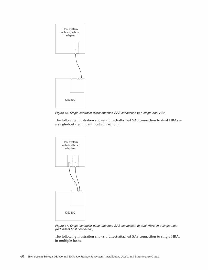
The following illustration shows a direct-attached SAS connection to dual HBAs ina single-host (redundant host connection).
The following illustration shows a direct-attached SAS connection to single HBAsin multiple hosts.
Host systemwith single host
adapter
DS3500
Figure 46. Single-controller direct-attached SAS connection to a single-host HBA
Host systemwith dual host
adapters
DS3500
Figure 47. Single-controller direct-attached SAS connection to dual HBAs in a single-host(redundant host connection)
60 IBM System Storage DS3500 and EXP3500 Storage Subsystem: Installation, User's, and Maintenance Guide

Direct-attached dual-controller connections:The following illustration shows a direct-attached SAS connection from eachcontroller to a single HBA in the same host (redundant host connection).
The following illustration shows multiple redundant direct-attached SAS hostconnections. This configuration is also the configuration to use for a dual-nodehost configuration.
Host systemwith single host
adapter
DS3500
Host systemwith single host
adapter
Figure 48. Single-controller direct-attached SAS connection to single HBAs in multiple hosts
Host systemwith dual host
adapters
DS3500
dg1fy
403
Figure 49. Dual-controller direct-attached SAS connection to two HBAs in the same host(redundant host connection)
Chapter 3. Cabling the storage subsystem and storage enclosure 61
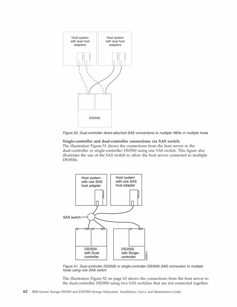
Single-controller and dual-controller connections via SAS switch:The illustration Figure 51 shows the connections from the host server to thedual-controller or single-controller DS3500 using one SAS switch. This figure alsoillustrates the use of the SAS switch to allow the host server connected to multipleDS3500s.
The illustration Figure 52 on page 63 shows the connections from the host server tothe dual-controller DS3500 using two SAS switches that are not connected together.
Host systemwith dual host
adapters
DS3500
Host systemwith dual host
adapters
Figure 50. Dual-controller direct-attached SAS connections to multiple HBAs in multiple hosts
SAS switch
Host systemwith one SAShost adapter
Host systemwith one SAShost adapter
DS3500with Dual-controller
DS3500with Single-controller
e35i0
011
Figure 51. Dual-controller DS3500 or single-controller DS3500 SAS connection to multiplehosts using one SAS switch
62 IBM System Storage DS3500 and EXP3500 Storage Subsystem: Installation, User's, and Maintenance Guide
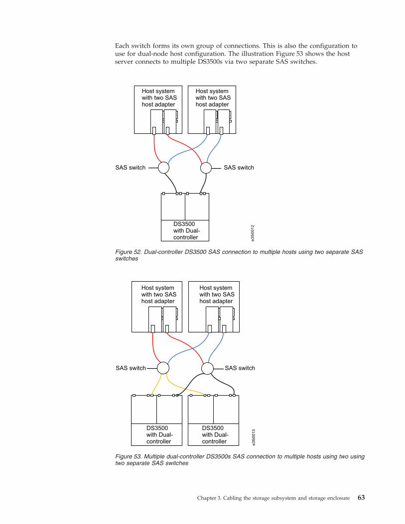
Each switch forms its own group of connections. This is also the configuration touse for dual-node host configuration. The illustration Figure 53 shows the hostserver connects to multiple DS3500s via two separate SAS switches.
SAS switch SAS switch
Host systemwith two SAShost adapter
Host systemwith two SAShost adapter
DS3500with Dual-controller
e35i0
012
Figure 52. Dual-controller DS3500 SAS connection to multiple hosts using two separate SASswitches
SAS switch SAS switch
Host systemwith two SAShost adapter
Host systemwith two SAShost adapter
e35i0
013DS3500
with Dual-controller
DS3500with Dual-controller
Figure 53. Multiple dual-controller DS3500s SAS connection to multiple hosts using two usingtwo separate SAS switches
Chapter 3. Cabling the storage subsystem and storage enclosure 63
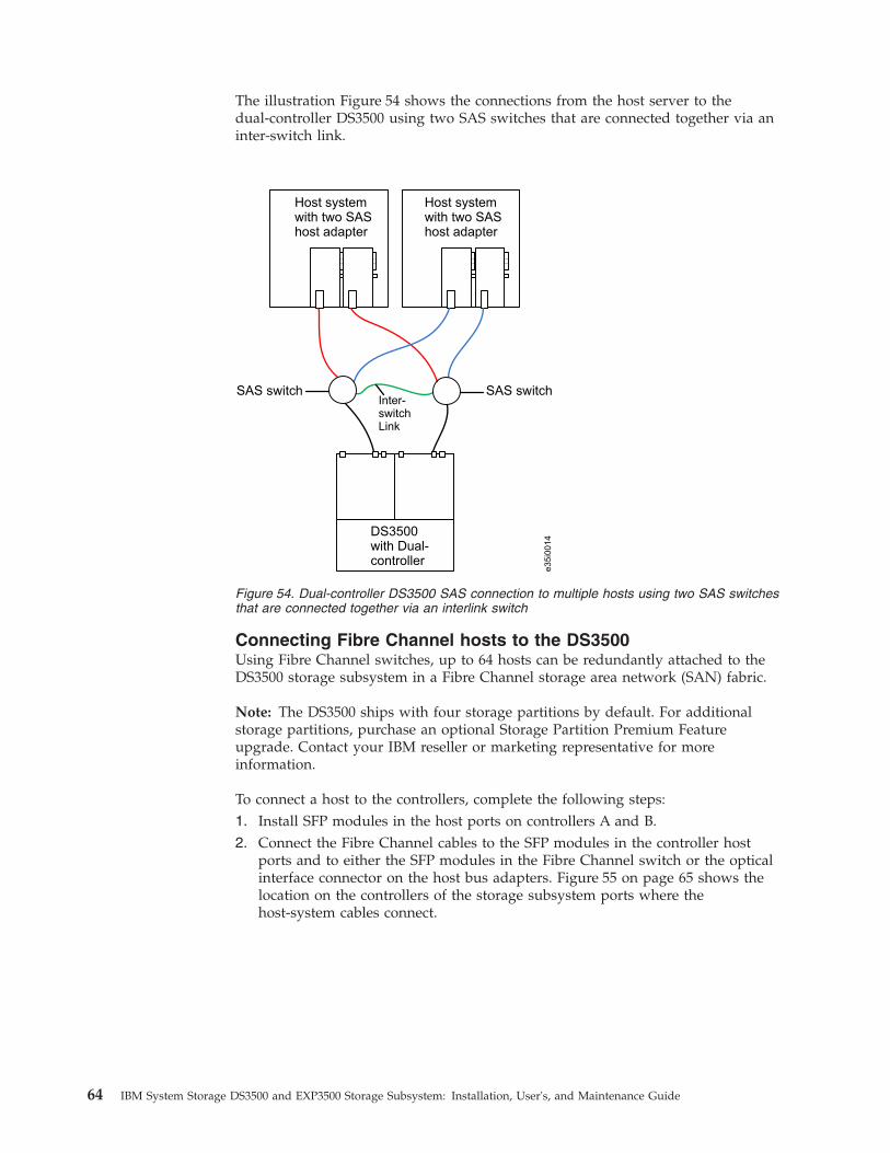
The illustration Figure 54 shows the connections from the host server to thedual-controller DS3500 using two SAS switches that are connected together via aninter-switch link.
Connecting Fibre Channel hosts to the DS3500Using Fibre Channel switches, up to 64 hosts can be redundantly attached to theDS3500 storage subsystem in a Fibre Channel storage area network (SAN) fabric.
Note: The DS3500 ships with four storage partitions by default. For additionalstorage partitions, purchase an optional Storage Partition Premium Featureupgrade. Contact your IBM reseller or marketing representative for moreinformation.
To connect a host to the controllers, complete the following steps:1. Install SFP modules in the host ports on controllers A and B.2. Connect the Fibre Channel cables to the SFP modules in the controller host
ports and to either the SFP modules in the Fibre Channel switch or the opticalinterface connector on the host bus adapters. Figure 55 on page 65 shows thelocation on the controllers of the storage subsystem ports where thehost-system cables connect.
DS3500with Dual-controller
SAS switch SAS switch
Host systemwith two SAShost adapter
Host systemwith two SAShost adapter
Inter-switchLink
e35i0
014
DS3500with Dual-controller
Figure 54. Dual-controller DS3500 SAS connection to multiple hosts using two SAS switchesthat are connected together via an interlink switch
64 IBM System Storage DS3500 and EXP3500 Storage Subsystem: Installation, User's, and Maintenance Guide
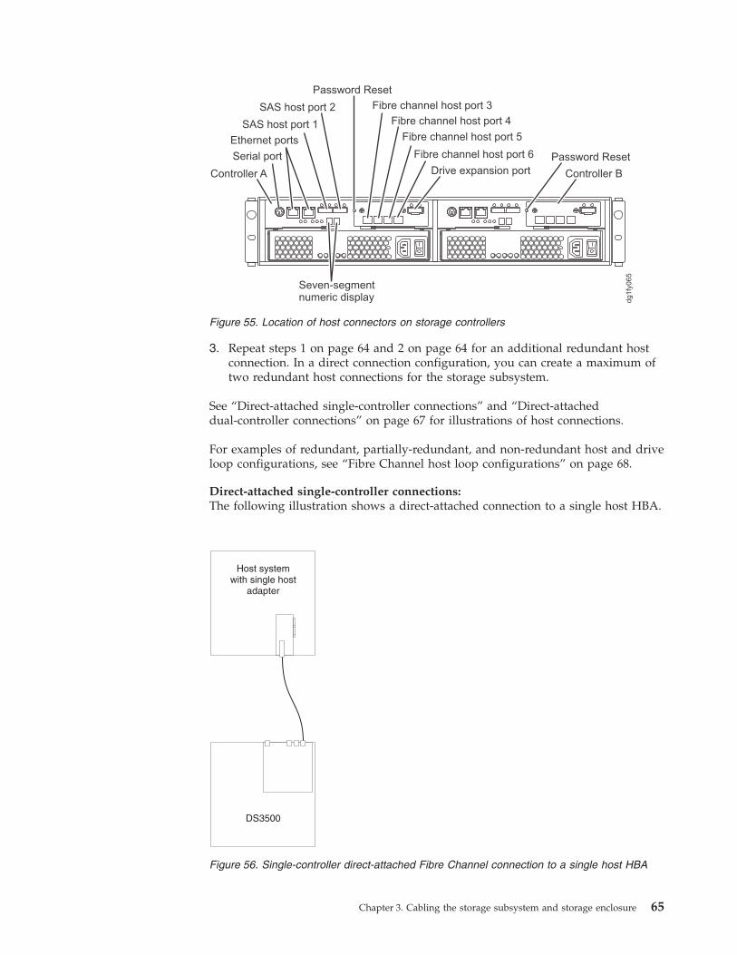
3. Repeat steps 1 on page 64 and 2 on page 64 for an additional redundant hostconnection. In a direct connection configuration, you can create a maximum oftwo redundant host connections for the storage subsystem.
See “Direct-attached single-controller connections” and “Direct-attacheddual-controller connections” on page 67 for illustrations of host connections.
For examples of redundant, partially-redundant, and non-redundant host and driveloop configurations, see “Fibre Channel host loop configurations” on page 68.
Direct-attached single-controller connections:The following illustration shows a direct-attached connection to a single host HBA.
Serial port
Ethernet ports
SAS host port 1
SAS host port 2 Fibre channel host port 3
Controller A
Fibre channel host port 4
Fibre channel host port 5
Fibre channel host port 6
Seven-segmentnumeric display
Controller B
dg1fy
065
Password Reset
Password Reset
Drive expansion port
Figure 55. Location of host connectors on storage controllers
Host systemwith single host
adapter
DS3500
Figure 56. Single-controller direct-attached Fibre Channel connection to a single host HBA
Chapter 3. Cabling the storage subsystem and storage enclosure 65
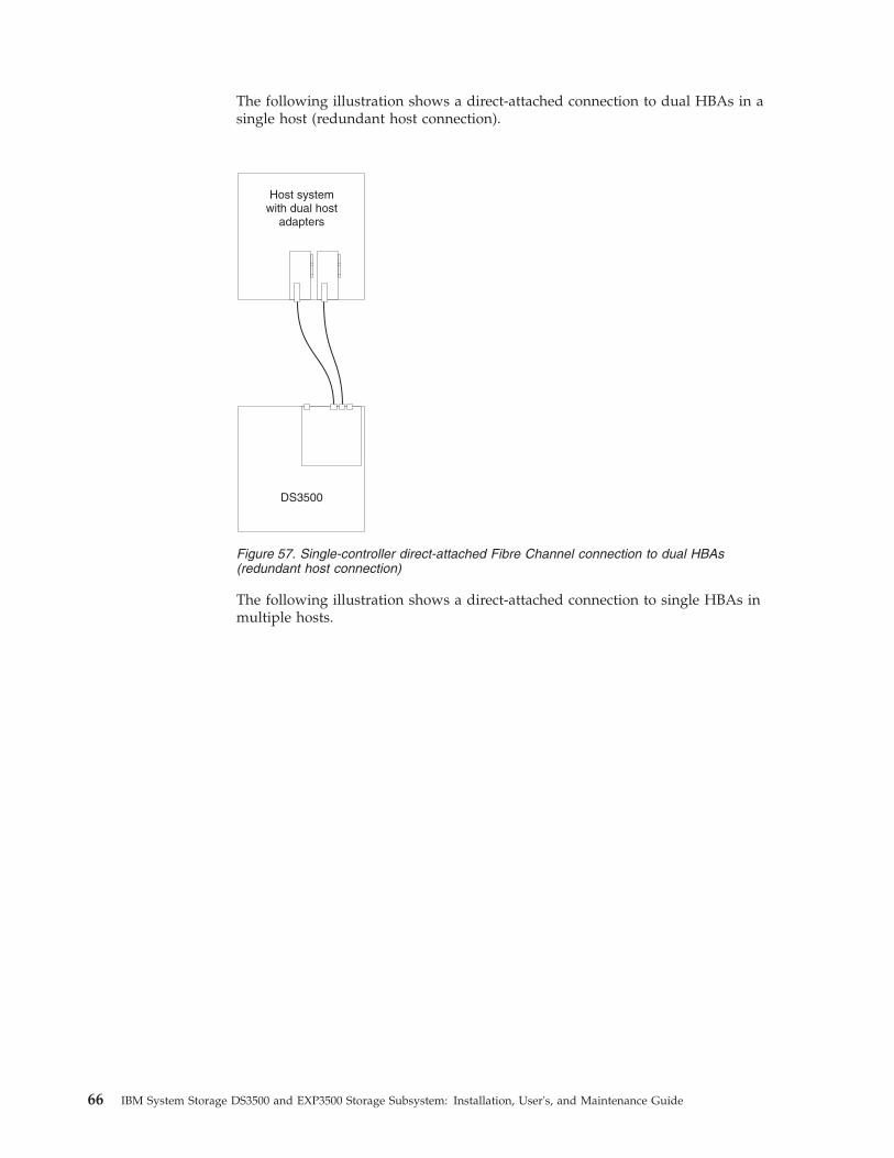
The following illustration shows a direct-attached connection to dual HBAs in asingle host (redundant host connection).
The following illustration shows a direct-attached connection to single HBAs inmultiple hosts.
Host systemwith dual host
adapters
DS3500
Figure 57. Single-controller direct-attached Fibre Channel connection to dual HBAs(redundant host connection)
66 IBM System Storage DS3500 and EXP3500 Storage Subsystem: Installation, User's, and Maintenance Guide

Direct-attached dual-controller connections:The following illustration shows a direct-attached connection from each controllerto a single HBA in the same host (redundant host connection).
The following illustration shows multiple redundant direct-attached hostconnections.
Host systemwith single host
adapter
DS3500
Host systemwith single host
adapter
Figure 58. Single-controller direct-attached Fibre Channel connection to single HBAs inmultiple hosts
Host systemwith dual host
adapters
DS3500
dg1fy
403
Figure 59. Dual-controller direct-attached Fibre Channel connection to two HBAs in the samehost (redundant host connection)
Chapter 3. Cabling the storage subsystem and storage enclosure 67
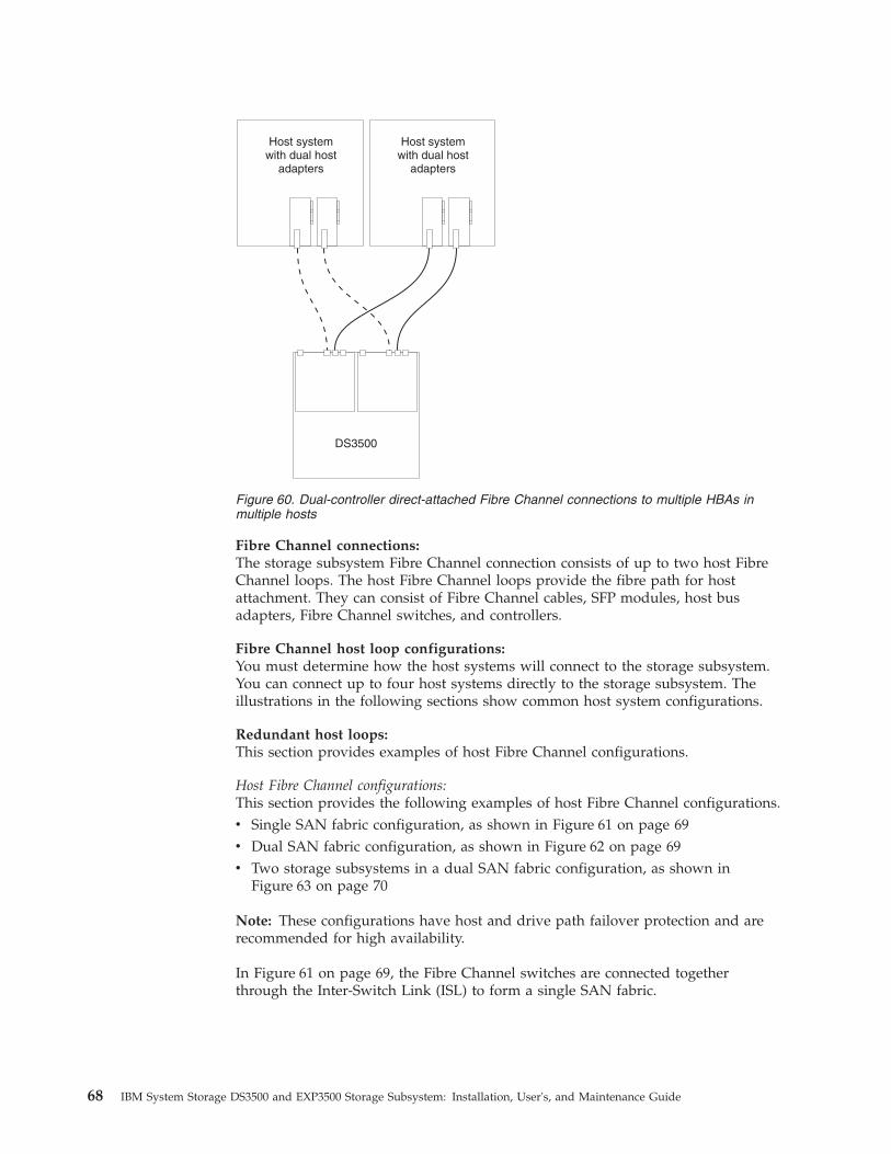
Fibre Channel connections:The storage subsystem Fibre Channel connection consists of up to two host FibreChannel loops. The host Fibre Channel loops provide the fibre path for hostattachment. They can consist of Fibre Channel cables, SFP modules, host busadapters, Fibre Channel switches, and controllers.
Fibre Channel host loop configurations:You must determine how the host systems will connect to the storage subsystem.You can connect up to four host systems directly to the storage subsystem. Theillustrations in the following sections show common host system configurations.
Redundant host loops:This section provides examples of host Fibre Channel configurations.
Host Fibre Channel configurations:This section provides the following examples of host Fibre Channel configurations.v Single SAN fabric configuration, as shown in Figure 61 on page 69v Dual SAN fabric configuration, as shown in Figure 62 on page 69v Two storage subsystems in a dual SAN fabric configuration, as shown in
Figure 63 on page 70
Note: These configurations have host and drive path failover protection and arerecommended for high availability.
In Figure 61 on page 69, the Fibre Channel switches are connected togetherthrough the Inter-Switch Link (ISL) to form a single SAN fabric.
Host systemwith dual host
adapters
DS3500
Host systemwith dual host
adapters
Figure 60. Dual-controller direct-attached Fibre Channel connections to multiple HBAs inmultiple hosts
68 IBM System Storage DS3500 and EXP3500 Storage Subsystem: Installation, User's, and Maintenance Guide
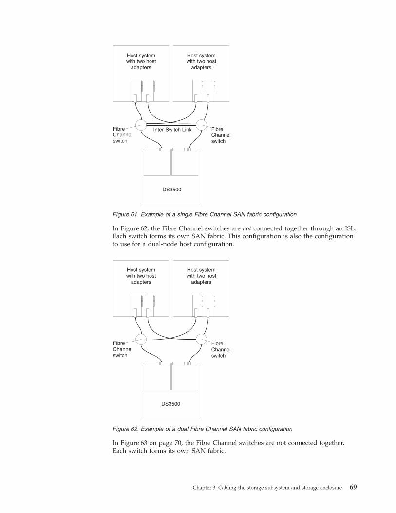
In Figure 62, the Fibre Channel switches are not connected together through an ISL.Each switch forms its own SAN fabric. This configuration is also the configurationto use for a dual-node host configuration.
In Figure 63 on page 70, the Fibre Channel switches are not connected together.Each switch forms its own SAN fabric.
Host systemwith two host
adapters
Host systemwith two host
adapters
FibreChannelswitch
FibreChannelswitch
Inter-Switch Link
DS3500
Figure 61. Example of a single Fibre Channel SAN fabric configuration
Host systemwith two host
adapters
Host systemwith two host
adapters
FibreChannelswitch
FibreChannelswitch
DS3500
Figure 62. Example of a dual Fibre Channel SAN fabric configuration
Chapter 3. Cabling the storage subsystem and storage enclosure 69
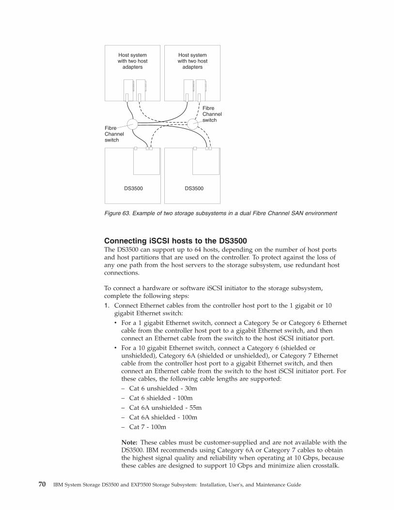
Connecting iSCSI hosts to the DS3500The DS3500 can support up to 64 hosts, depending on the number of host portsand host partitions that are used on the controller. To protect against the loss ofany one path from the host servers to the storage subsystem, use redundant hostconnections.
To connect a hardware or software iSCSI initiator to the storage subsystem,complete the following steps:1. Connect Ethernet cables from the controller host port to the 1 gigabit or 10
gigabit Ethernet switch:v For a 1 gigabit Ethernet switch, connect a Category 5e or Category 6 Ethernet
cable from the controller host port to a gigabit Ethernet switch, and thenconnect an Ethernet cable from the switch to the host iSCSI initiator port.
v For a 10 gigabit Ethernet switch, connect a Category 6 (shielded orunshielded), Category 6A (shielded or unshielded), or Category 7 Ethernetcable from the controller host port to a gigabit Ethernet switch, and thenconnect an Ethernet cable from the switch to the host iSCSI initiator port. Forthese cables, the following cable lengths are supported:– Cat 6 unshielded - 30m– Cat 6 shielded - 100m– Cat 6A unshielded - 55m– Cat 6A shielded - 100m– Cat 7 - 100m
Note: These cables must be customer-supplied and are not available with theDS3500. IBM recommends using Category 6A or Category 7 cables to obtainthe highest signal quality and reliability when operating at 10 Gbps, becausethese cables are designed to support 10 Gbps and minimize alien crosstalk.
Host systemwith two host
adapters
Host systemwith two host
adapters
FibreChannelswitch
FibreChannelswitch
DS3500 DS3500
Figure 63. Example of two storage subsystems in a dual Fibre Channel SAN environment
70 IBM System Storage DS3500 and EXP3500 Storage Subsystem: Installation, User's, and Maintenance Guide

The quality of Category 6 cables can vary between different manufacturersand even different manufactured lots. Please contact your IBM representativeor reseller if you require any clarifications.
Figure 17 on page 32 shows the host ports.2. Create a redundant host connection:
v If the storage subsystem is a single-controller storage subsystem, connect anEthernet cable from the second host port on the controller to a gigabitEthernet switch.
v If the storage subsystem is a dual-controller storage subsystem, connect anEthernet cable from the host port on the other controller on the storagesubsystem to a gigabit Ethernet switch.
Note: Do not configure any two interfaces on the same subnet. If you are usingDHCP on more than one interface, multiple interfaces can end up on the samesubnet. Direct iSCSI connections from the host to the storage subsystem are notsupported.
For illustrations of host connections, see “Single-controller iSCSI connections” and“Dual-controller iSCSI configurations” on page 73.
Single-controller iSCSI connections:The following illustration shows a single controller storage subsystem that isattached to a single host. This configuration has no redundancy.
A system with dual iSCSI ports can provide enhanced performance compared to asystem that uses only one iSCSI port.
The following illustration is an example of a host that uses multiple ports attachedto a single-controller configuration. This configuration provides some pathredundancy.
1 Gigabit/10 GigabitEthernet switch
Host systemwith one iSCSI
connector
DS3500
e35i0
001
Figure 64. Single-host, single-controller iSCSI configuration
Chapter 3. Cabling the storage subsystem and storage enclosure 71

The following illustration is an example of multiple single-port host systems thatare connected to a single-controller DS3500 using multiple connections.
For host configurations, the following illustration is an example of a multiple-host,multiple-port, single-controller, and redundant-path configuration.
DS3500
Host systemwith two iSCSI
connectors
e35i0
002
1 Gigabit/10 GigabitEthernet switch
Figure 65. Multiple-port, single-controller iSCSI configuration
DS3500
Host systemwith one iSCSI
connector
Host systemwith one iSCSI
connector
e35i0
003
1 Gigabit/10 GigabitEthernet switch
Figure 66. Multiple single-port hosts, single-controller iSCSI configuration
72 IBM System Storage DS3500 and EXP3500 Storage Subsystem: Installation, User's, and Maintenance Guide
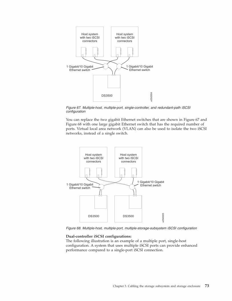
You can replace the two gigabit Ethernet switches that are shown in Figure 67 andFigure 68 with one large gigabit Ethernet switch that has the required number ofports. Virtual local area network (VLAN) can also be used to isolate the two iSCSInetworks, instead of a single switch.
Dual-controller iSCSI configurations:The following illustration is an example of a multiple port, single-hostconfiguration. A system that uses multiple iSCSI ports can provide enhancedperformance compared to a single-port iSCSI connection.
DS3500
Host systemwith two iSCSI
connectors
Host systemwith two iSCSI
connectors
1 Gigabit/10 GigabitEthernet switch
1 Gigabit/10 GigabitEthernet switch
e35i0
004
Figure 67. Multiple-host, multiple-port, single-controller, and redundant-path iSCSIconfiguration
DS3500
Host systemwith two iSCSI
connectors
Host systemwith two iSCSI
connectors
DS3500
1 Gigabit/10 GigabitEthernet switch
1 Gigabit/10 GigabitEthernet switch
e35i0
005
Figure 68. Multiple-host, multiple-port, multiple-storage-subsystem iSCSI configuration
Chapter 3. Cabling the storage subsystem and storage enclosure 73

For host configurations, the following illustration is an example of a multiple-host,multiple-port, and redundant path and controller configuration.
You can replace the two gigabit Ethernet switches that are shown in Figure 70 withone large gigabit Ethernet switch that has the required number of ports. Virtuallocal area network (VLAN) can also be used to isolate the two iSCSI networks,instead of a single switch.
Figure 71 on page 75 shows an example of a multiple-host, multiple-port, andmultiple-fabric (Fibre Channel or iSCSI, and SAS) configuration.
Host systemwith two iSCSI
connectors
DS3500
1 Gigabit/10 GigabitEthernet switch
e35i0
006
Figure 69. Single-host, multiple-port, dual-controller iSCSI configuration
DS3500
Host systemwith two iSCSI
connectors
Host systemwith two iSCSI
connectors
1 Gigabit/10 GigabitEthernet switch
1 Gigabit/10 GigabitEthernet switch
e35i0
007
Figure 70. Multiple-host, multiple-port, dual-controller iSCSI configuration
74 IBM System Storage DS3500 and EXP3500 Storage Subsystem: Installation, User's, and Maintenance Guide

Overview of installing an IBM BladeCenter configuration toconnect to a DS3500
This section contains an overview of and guidelines for installing an IBMBladeCenter configuration to connect to a DS3500.
Before you install the BladeCenter configuration:v Ensure that the BladeCenter chassis, blade server, SAS connectivity module, and
SAS expansion card are supported. Go to http://www.ibm.com/servers/storage/support/disk/, select the link for the DS3500, and see theinteroperability matrix.
v Ensure that an Advanced Management Module is installed in the BladeCenterchassis. The latest level of management-module firmware is available athttp://www.ibm.com/bladecenter/.
v For the latest SAS connectivity module firmware, SAS expansion card firmware,blade server BIOS code, and device drivers, see http://www.ibm.com/systems/support/.
Installing the BladeCenter configurationTo install the IBM BladeCenter SAS Expansion Card (CFFv), IBM BladeCenter SASConnectivity Module, and blade server, complete the following steps:1. Install an IBM BladeCenter SAS Expansion Card (CFFv) in each blade server
that you want to connect to the DS3500. See the documentation that is shippedwith the SAS expansion card for installation requirements and procedures.
2. Install the blade servers in the BladeCenter chassis. See the documentation thatis shipped with the blade server for installation requirements and procedures.
DS3500
Host with dualfibre shannel or
iSCSI ports
Host with dualSAS HBAs
Fibre Channelor
1 Gigabit/10 GigabitEthernet switch
e35i0
008
FibreChannel oriSCSI ports
SAS ports
SAS ports
FibreChannel oriSCSI ports
Figure 71. Example of a multiple-host, multiple-port, and multiple-fabric (Fibre Channel oriSCSI, and SAS) configuration
Chapter 3. Cabling the storage subsystem and storage enclosure 75
3. Install the IBM BladeCenter SAS Connectivity Modules in the I/O bays inBladeCenter unit. See the documentation that comes with the SAS connectivitymodules for installation requirements and procedures.
4. Go to “Connecting BladeCenter hosts to the DS3500.”
Connecting BladeCenter hosts to the DS3500The dual-controller DS3500 comes with two SAS host connectors on eachcontroller, enabling up to 28 blade servers in two BladeCenter units to beredundantly connected to the storage subsystem.
To protect against the loss of any one path from the host blade servers to theDS3500, use redundant host connections.
To connect a SAS expansion card that is installed in a blade server to the DS3500,complete the following steps:1. Connect a SAS cable from the SAS host connector on the DS3500 storage
controller to any SAS port on an IBM BladeCenter SAS Connectivity Module,which is installed in a BladeCenter unit (port 3 is recommended).
2. To create a redundant host connection, connect a SAS cable from a second SASconnectivity module to a host connector on the other controller in the DS3500.You can create a maximum of two redundant host connections in adual-controller DS3500, one connection each from the blade center to theDS3500 controller host port as shown in Figure 72 on page 77.Attention: You can connect only one DS3500 to the BladeCenter SASConnectivity Module. No other external devices can be connected to the SASconnectivity module.
3. (Optional) For additional storage, connect EXP3500 storage enclosures to theDS3500. See the illustration to configure storage enclosures inFigure 38 on page50.
Figure 72 on page 77 shows an example of a DS3500 that is connected to oneBladeCenter unit.
76 IBM System Storage DS3500 and EXP3500 Storage Subsystem: Installation, User's, and Maintenance Guide

Cabling the DS3500 and EXP3500 ac power suppliesTo connect the DS3500 and EXP3500 ac power-supply cords, complete thefollowing steps:1. Connect a power cord to a power supply in the DS3500 or EXP3500.2. Attach the power cord to the strain relief guide.3. Repeat steps 1 and 2 for the second power supply.4. Connect the other end of each power cord to a correctly grounded electrical
receptacle. For maximum protection against power loss, connect each of thetwo power supplies to a different power source.
Figure 72. Example of a DS3500 that is connected to a BladeCenter unit
Chapter 3. Cabling the storage subsystem and storage enclosure 77
Cabling the DS3500 and EXP3500 dc power suppliesStatement 29
CAUTION:This equipment is designed to enable the connection of the earthed conductor ofthe dc supply circuit to the earthing conductor at the equipment. If thisconnection is made, all of the following conditions must be met:
v This equipment must be connected directly to the dc supply system earthingelectrode conductor or to a bonding jumper from an earthing terminal bar orbus to which the dc supply system earthing electrode conductor is connected.
v This equipment must be located in the same immediate area (such as adjacentcabinets) as any other equipment that has a connection between the earthedconductor of the same dc supply circuit and the earthing conductor, and alsothe point of earthing of the dc system. The dc system shall not be earthedelsewhere.
v The dc supply source must be located within the same premises as thisequipment.
v Switching or disconnecting devices must not be in the earthed circuitconductor between the dc source and the point of connection of the earthingelectrode conductor.
Statement 34
CAUTION:To reduce the risk of electric shock or energy hazards:
v This equipment must be installed by trained service personnel in arestricted-access location, as defined by the NEC and IEC 60950-1, FirstEdition, The Standard for Safety of Information Technology Equipment.
v Connect the equipment to a reliably grounded safety extra low voltage (SELV)source. An SELV source is a secondary circuit that is designed so that normaland single fault conditions do not cause the voltages to exceed a safe level (60V direct current).
v Incorporate a readily available approved and rated disconnect device in thefield wiring.
v See the specifications in the product documentation for the requiredcircuit-breaker rating for branch circuit overcurrent protection.
v Use copper wire conductors only. See the specifications in the productdocumentation for the required wire size.
v See the specifications in the product documentation for the required torquevalues for the wiring-terminal nuts.
To connect the DS3500 and EXP3500 dc power-supply cables, complete thefollowing steps:1. Ensure that the power on-off switch on both of the dc power supply and fan
units in the chassis are in the off position.
78 IBM System Storage DS3500 and EXP3500 Storage Subsystem: Installation, User's, and Maintenance Guide
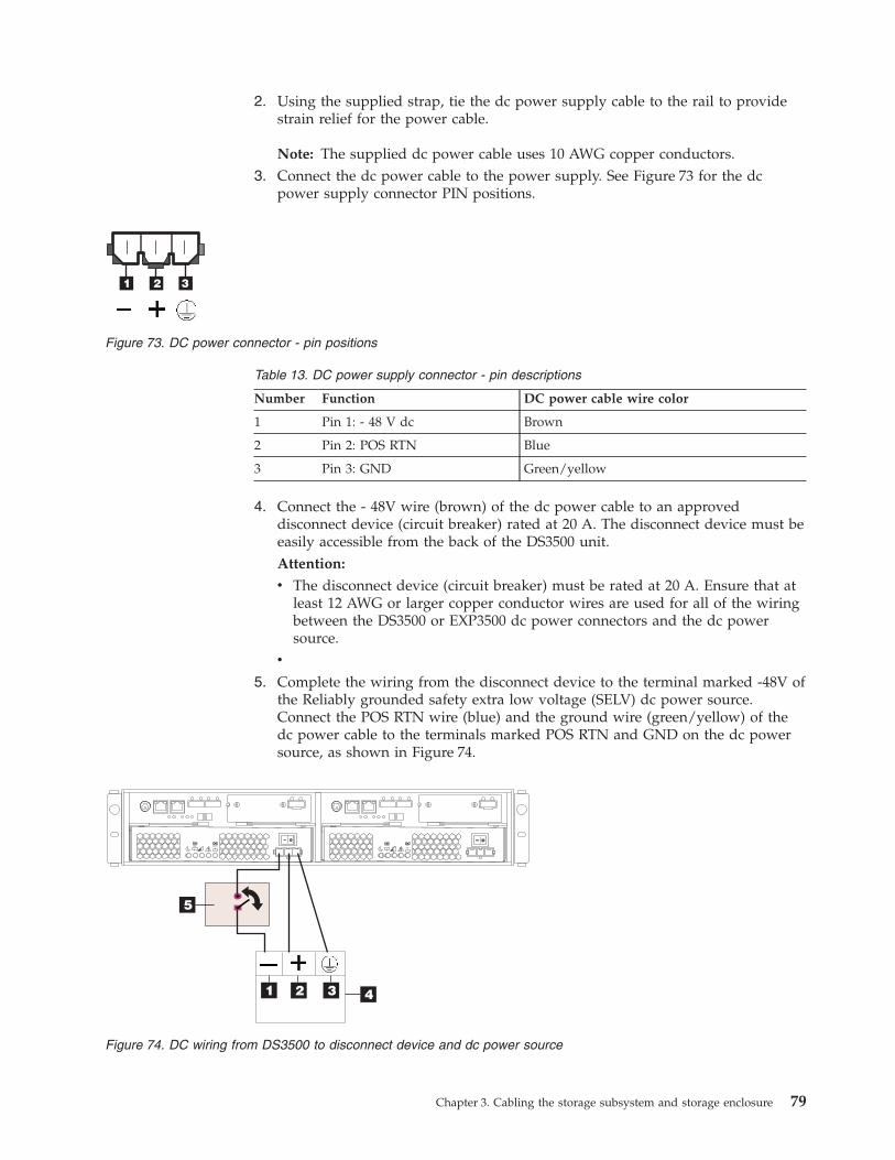
2. Using the supplied strap, tie the dc power supply cable to the rail to providestrain relief for the power cable.
Note: The supplied dc power cable uses 10 AWG copper conductors.3. Connect the dc power cable to the power supply. See Figure 73 for the dc
power supply connector PIN positions.
Table 13. DC power supply connector - pin descriptions
Number Function DC power cable wire color
1 Pin 1: - 48 V dc Brown
2 Pin 2: POS RTN Blue
3 Pin 3: GND Green/yellow
4. Connect the - 48V wire (brown) of the dc power cable to an approveddisconnect device (circuit breaker) rated at 20 A. The disconnect device must beeasily accessible from the back of the DS3500 unit.Attention:
v The disconnect device (circuit breaker) must be rated at 20 A. Ensure that atleast 12 AWG or larger copper conductor wires are used for all of the wiringbetween the DS3500 or EXP3500 dc power connectors and the dc powersource.
v
5. Complete the wiring from the disconnect device to the terminal marked -48V ofthe Reliably grounded safety extra low voltage (SELV) dc power source.Connect the POS RTN wire (blue) and the ground wire (green/yellow) of thedc power cable to the terminals marked POS RTN and GND on the dc powersource, as shown in Figure 74.
Figure 73. DC power connector - pin positions
Figure 74. DC wiring from DS3500 to disconnect device and dc power source
Chapter 3. Cabling the storage subsystem and storage enclosure 79
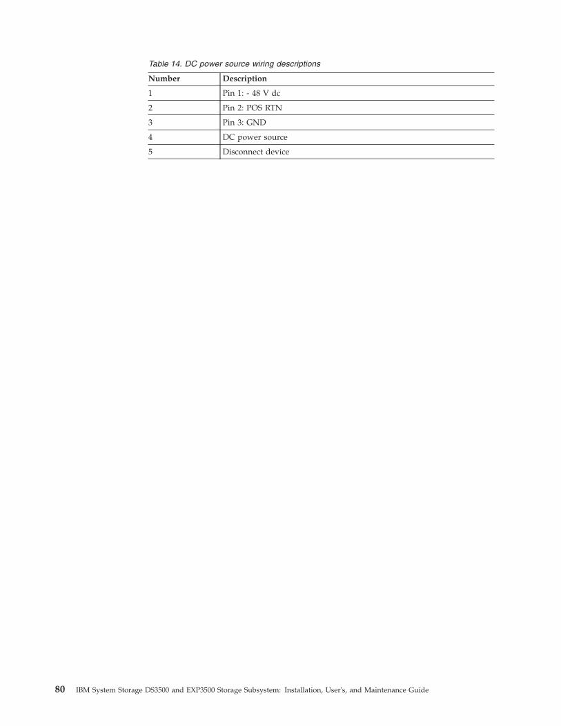
Table 14. DC power source wiring descriptions
Number Description
1 Pin 1: - 48 V dc
2 Pin 2: POS RTN
3 Pin 3: GND
4 DC power source
5 Disconnect device
80 IBM System Storage DS3500 and EXP3500 Storage Subsystem: Installation, User's, and Maintenance Guide

Chapter 4. Operating the storage subsystem and storageenclosure
This section describes operating procedures for the storage subsystem and storageenclosure.
To ensure optimal operation of the storage subsystem and storage enclosure, see“Best practices guidelines” on page 8.
Performing the health check processUse the health check process to help you verify and maintain the optimalperformance of the storage configuration. The information that you collect in thesesteps also helps provide IBM Service with important information that is neededduring a service call.
Perform the following health check tasks after the initial configuration of thestorage subsystem and after all configuration sessions.1. Monitor the Recovery Guru in the Storage Manager software for any obvious
storage subsystem errors or problem conditions.2. Gather and save the following storage subsystem event logs for review by IBM
Service. These event logs should be gathered periodically for regular healthcheck monitoring regardless of the state of the Recovery Guru. (You can collectall these logs at once and compress them into a single file by clicking theSupport tab and then Gather Support Information in the SubsystemManagement window.)v DS3500 storage subsystem management event log (MEL)v Storage Subsystem Profile or DS3500 Profilev SAS PHY error logIn addition, you should also collect event logs for the host servers that havemapped logical drives from the storage subsystem.Attention: Save these event-log files to a server disk that will remainaccessible in the event of a DS3500 storage configuration failure. Do not savethese event log files only to a LUN in the DS3500 storage subsystem.
3. Use the Storage Subsystem Profile or DS3500 Profile to ensure that thefollowing firmware levels are at the latest versions:v Controller firmwarev ESM firmwarev Drive firmwareIf the firmware is not up-to-date, upgrade the firmware and software to thelatest level that is applicable to the storage configuration. See “Software andhardware compatibility and upgrades” on page 15 for information about whereto find the latest firmware and software.Attention: You must resolve Recovery Guru errors or problems before youupgrade firmware.Save the storage subsystem profile before you perform any controller or ESMfirmware upgrades. Save the storage subsystem profile and all .cfg files to aserver disk that will remain accessible in the event of a DS3500 storageconfiguration failure.
© Copyright IBM Corp. 2010, 2013 81
4. Use the Storage Subsystem Profile or DS3500 Profile to ensure that thefollowing functions are enabled:v For all DS3500 models, enable Media Scan both at the controller level and at
the LUN level.v For all DS3500 models, enable the read/write cache. In addition, use the
Storage Subsystem Profile to ensure that cache is matched between thecontrollers.
Set a regular schedule of periodic health check evaluations to keep the firmwarelevels current and to preserve optimal data access and performance.
Hardware inspectionIn addition to the health check process, regular hardware inspection andmaintenance helps to support the optimal performance of the storageconfiguration. Periodically inspect the components of the storage configuration.
For best results, follow these guidelines:v Maintain an up-to-date storage subsystem profile for the storage configuration.
Save the profile to a server disk that will remain accessible in case of a DS3500storage configuration failure. Do not save the profile only to a LUN in thestorage subsystem.
v Develop a change-management plan. The plan should include schedules forupdating subsystem firmware and server host software.
Note: Some updates might require storage subsystem downtime.v Use applicable IBM-approved cables for all situations. Note in the configuration
documentation whether any cables are not IBM-approved.v Create and maintain a cabling diagram of the current configuration. Keep this
diagram updated as you make configuration changes, and keep the cablingdiagram available for review.
v Create and maintain a list of other components that are being used within thecabling diagram (such as the host system and other attached devices).
v Ensure that all controllers and ESMs are correctly seated.v Ensure that all drives are correctly seated.v Ensure that cables are managed correctly.v Ensure proper air flow and temperature for all components in the storage
configuration.
You can find details about many of these inspection and maintenanceresponsibilities in other sections of this document.
In addition to these inspection and maintenance responsibilities, conduct trainingfor staff that support storage configurations. Although training is not a part of thehealth check process, training reduces the potential for configuration problems andcontributes to the correct operation of the system.
Turning on the storage subsystemThis section contains instructions for turning on the storage subsystem undernormal situations. “Turning off the storage subsystem” on page 95 containsinstructions for turning off the storage subsystem under normal and emergencysituations. When you turn on and turn off the storage subsystem, be sure to use
82 IBM System Storage DS3500 and EXP3500 Storage Subsystem: Installation, User's, and Maintenance Guide
the startup sequence that is described in this section. If you are turning on thestorage subsystem after an emergency shutdown or power outage, see “Restoringpower after an unexpected shutdown” on page 98.
The following procedure addresses two situations:v The entire storage subsystem has been shut down (the main circuit breakers for
the rack are off).v Some storage enclosures are being powered-on while others remain online (the
main circuit breakers for the rack are on). You might encounter this if you areadding a storage enclosure to increase storage capacity.Attention:
1. Repeatedly turning the power off and on without waiting for the drives tospin down can damage the drives. Always wait at least 70 seconds after youturn off the power before you turn it on again.
2. If you are connecting a power cord to a storage subsystem or storageenclosure, turn off both of its power switches first. If the main circuit breakeris off, ensure that both power switches are off on each storage enclosure inthe rack before you turn on the main circuit breakers.
1. Are the main circuit breakers turned on?v Yes: Turn off both power switches on each enclosure that you intend to
connect to the power.v No: Turn off both power switches on all enclosures in the storage subsystem.
2. Ensure that all power cords are connected.
Note: If the power cords are not connected, turn off both power switches on allmodules in the configuration before you connect power cords or turn on themain circuit breakers.
3. If the main circuit breakers are turned off, turn them on.Attention: You must turn on power to each attached storage enclosure beforeyou turn on power to the storage subsystem so that the controllers recognize alldrives in the configuration during the startup process.
4. If you have enclosures with dc power supplies, turn on the disconnect devicethat you installed on the -48V line in “Cabling the DS3500 and EXP3500 dcpower supplies” on page 78.
5. Turn on both power switches on the rear of each storage enclosure that isattached to the storage subsystem. While each storage enclosure powers up, thegreen and amber LEDs on the front and rear of the storage enclosure turn onand off intermittently. Depending on the configuration, it can take severalminutes for each storage enclosure to power-on.Check the LEDs on the front and rear of all the storage enclosures. Ensure thatno amber LEDs are lit on any of the storage enclosures.
6. Turn on both power switches on the rear of the storage subsystem. Figure 75 onpage 84 shows the locations of the ac power switches. Figure 76 on page 84shows the locations of the dc power switches.
Chapter 4. Operating the storage subsystem and storage enclosure 83

Depending on the number of storage enclosures in the configuration, thestorage subsystem might take up to 10 minutes to fully power-on. While eachstorage enclosure powers-on, the green and amber LEDs on the front and rearof the storage enclosure turn on and off intermittently. The cache batterybackup self-test might take up to an additional 15 minutes to be completed.During this time, the LEDs on the front and rear of the storage subsystemmight flash intermittently.
7. Determine the status of all storage subsystems and components in theconfiguration by completing the following steps:a. Check all LEDs on each component in the storage enclosures. Ensure that
all the LEDs show normal status. For more information about LED statusfor storage enclosures, see “Checking the LEDs” on page 88.
b. Check all LEDs on each component in the storage subsystem. Ensure thatall the LEDs show normal status. For information about LED status, seeChapter 6, “Solving problems,” on page 161.
c. Open the Subsystem Management window, and display the status of thestorage subsystem.
8. Are the LEDs indicating normal operation, and is the status Optimal on all theconfiguration components?v Yes: The procedure is complete.v No: Go to step 9.
9. Diagnose and correct the fault by completing the following steps:a. Run the Storage Manager Recovery Guru by clicking Recovery Guru in the
Subsystem Management window toolbar.b. Complete the recovery procedure.
If the Recovery Guru directs you to replace a failed component, use theindividual LEDs on the storage subsystem to locate the specific failedcomponent. For troubleshooting procedures, see Chapter 6, “Solvingproblems,” on page 161.
c. When the recovery procedure is completed, select Recheck in the RecoveryGuru. This action runs the Recovery Guru again to make sure that theproblem is corrected.
d. If the problem remains, contact your IBM technical-support representative.
Powerswitch
Powerconnector
Powerswitch
Powerconnector
Figure 75. Power-supply switches and connectors for DS3500 ac models
Powerswitch
Powerconnector
Powerswitch
Powerconnector
Figure 76. Power-supply switches and connectors for DS3500 dc models
84 IBM System Storage DS3500 and EXP3500 Storage Subsystem: Installation, User's, and Maintenance Guide

Installing the Storage Manager ClientFor instructions to install the Storage Manager software, see the IBM System StorageDS Storage Manager Version 10 Installation and Host Support Guide (for DS StorageManager V10.77 or earlier) or the IBM System Storage DS Storage Manager Version10.8 Installation and Host Support Guide (for DS Storage Manager V10.83 or later) forthe applicable operating system. The document is in the Documentation folder onthe IBM System Storage DS3500 Support DVD. Use that document and the onlinehelp to configure the logical drives, partitions, and so on for the controllers. Followthe instructions in the operating-system documentation to make the new logicaldrives accessible to the operating system. Do not proceed with the configurationsetup until you have completed the Storage Manager installation.
Assemble any additional items in preparation for software installation. These itemsmight include the following items:v HBA device driversv Controller firmwarev IP addresses for controllers (for out-of-band management only)v Additional documentation for hosts, HBAs, and storage enclosures
Save the storage subsystem profile before any planned system shutdown or afterany system additions, removals, or modifications (including firmware updates,logical drive creations, storage partitioning definitions, hardware changes, and soon). For instructions to save the storage subsystem profile, see the IBM SystemStorage DS Storage Manager Version 10 Installation and Host Support Guide (for DSStorage Manager V10.77 or earlier) or the IBM System Storage DS Storage ManagerVersion 10.8 Installation and Host Support Guide (for DS Storage Manager V10.83 orlater) for your operating system. Save the profile in a location other than thelogical drives that are created for the storage subsystem.
Always see the readme file that is included with the DS3500 Storage Subsystemfirmware package (whether the firmware is accessed by the Web or a CD) for anyspecial requirements or restrictions that apply to that firmware version.
Note: Be sure to install the Storage Manager event monitoring service to enablecontinuous monitoring of the status of the storage subsystem. For moreinformation about the importance of this information, see “Monitoring statusthrough software.”
Monitoring status through softwareUse the Storage Manager software to monitor the status of the storage subsystem.Run the software constantly, and check it frequently.
Note:
1. You can monitor only storage subsystems that are within the managementdomain of the storage-management software.
2. If you have not installed the Storage Manager Event Monitor service as part ofthe storage-management software installation, the Storage Manager EnterpriseManagement window must remain open. (If you close the window, you willnot receive any alert notifications from the managed storage subsystems.)For more information, see the Enterprise Management online help.
Chapter 4. Operating the storage subsystem and storage enclosure 85

Important: For instructions to install the DS Storage Manager software, see theIBM System Storage DS Storage Manager Version 10 Installation and Host SupportGuide (for DS Storage Manager V10.77 or earlier) or the IBM System Storage DSStorage Manager Version 10.8 Installation and Host Support Guide (for DS StorageManager V10.83 or later) for the applicable operating system. The document is inthe Documentation folder on the IBM System Storage DS3500 Support DVD.
To download the latest version of the Storage Manager software, controllerfirmware, NVSRAM firmware, and the latest ESM firmware, go tohttp://www.ibm.com/servers/storage/support/disk/.
The Storage Manager software provides the best way to diagnose and repairstorage-subsystem failures. The software can help you:v Determine the nature of the failurev Locate the failed componentv Determine the recovery procedures to repair the failure
Amber (needs attention) LEDs do not necessarily indicate which component hasfailed or must be replaced or which type of recovery procedure you must perform.In some cases (such as when a drive exceeds its Predictive Failure Analysis [PFA]threshold), the amber LED is not lit. Only the Storage Manager software can detectthe failure.
For example, the recovery procedure for a PFA flag (impending drive failure) on adrive varies depending on the drive status (hot spare, unassigned, RAID level,current logical drive status, and so on). Depending on the circumstances, a PFAflag on a drive can indicate a high risk of data loss (if the drive is in a RAID 0logical drive) or a minimal risk (if the drive is unassigned). Only the StorageManager software can identify the risk level and provide the necessary recoveryprocedures.
Note: For PFA flags, the system-error LED and drive status LEDs are not lit, sochecking the LEDs will not notify you of the failure, even if the risk of data loss ishigh.
Recovering from a storage-subsystem failure might require you to performprocedures other than replacing the component (such as backing up the logicaldrive). The Storage Manager software provides these procedures.
Attention: Not following the software-recovery procedures can result in data loss.In addition, always replace a failing component as soon as possible to minimizeadditional failures that might occur, causing loss of data access.
Firmware updatesAttention: Save the storage subsystem profile before you perform any controlleror ESM firmware upgrades. Save the profile and all configuration (.cfg) files to aserver disk that will remain accessible in the event of a DS3500 storageconfiguration failure. Do not save these files only to a LUN in the storagesubsystem.
To ensure the optimal operation of the storage subsystem and its attached storageenclosures, the ESM firmware, controller firmware, drive firmware, and theNVSRAM firmware must be up-to-date. Go to http://www.ibm.com/servers/storage/support/disk/ to get the latest updates.
86 IBM System Storage DS3500 and EXP3500 Storage Subsystem: Installation, User's, and Maintenance Guide

Always see the readme files that are included with the firmware packages for themost up-to-date information about firmware prerequisites, firmware updateinstructions, download-sequence information, and host I/O restrictions, if any.Apply the necessary updates before you configure the storage subsystem arraysand logical drives. Subscribe to My Support for automatic notifications of firmwareor Storage Manager software updates or any important information about theDS3500 storage subsystems (see “Product updates” on page 8).
Attention: Failure to observe the limitations, prerequisites, sequences, anddependencies in the readme file might result in a loss of data access.
Unless the readme file contains special requirements for the sequence in which youupgrade firmware, perform firmware upgrades in the following sequence:1. ESM firmware for the storage enclosures2. Controller firmware3. Controller NVSRAM4. Drive firmware
Troubleshooting the storage subsystemThe Storage Manager software is the best way to monitor the storage subsystem,diagnose a problem, and recover from a hardware failure. Run the StorageManager software continuously, and frequently check the configuration status.
To check the status of and identify a problem with the storage subsystem, completethe following steps. If a problem has occurred, use the Storage Manager softwareand the LEDs on the storage subsystem to help locate a failed component.1. Open the Subsystem Management window.2. Click the Summary tab, and view the status of the storage subsystem.3. Does any storage subsystem have a Needs Attention status?
v Yes: Go to step 4.v No: All components are Optimal. Go to step 5.
4. Click Recovery Guru on the toolbar. Perform the procedure in the RecoveryGuru to correct the problem. The Recovery Guru might direct you to replacethe failed component. If so, go to step 5.Attention: If the fault requires you to power-off an attached storage enclosure,you might have to cycle the power on the DS3500 storage subsystem and allremaining storage enclosures that are connected to the storage subsystem.Contact your IBM technical-support representative before you power-off anyattached storage enclosures.
5. Check the LEDs on the front and the rear of the storage enclosure. A green LEDindicates a normal status; an amber LED indicates a hardware fault.
6. Is an amber LED lit?v Yes: Locate and troubleshoot the failed components. See “Checking the
LEDs” on page 88.v No: You are finished with this procedure. If you are still experiencing a
problem with the storage subsystem, create, save, and print a storagesubsystem profile, and contact your IBM technical-support representative forassistance. When the recovery procedure is completed, select Recheck in theRecovery Guru to run the Recovery Guru again to ensure that the problem iscorrected.
Chapter 4. Operating the storage subsystem and storage enclosure 87
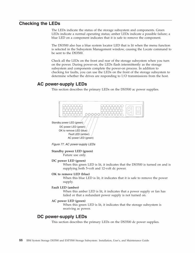
Checking the LEDsThe LEDs indicate the status of the storage subsystem and components. GreenLEDs indicate a normal operating status; amber LEDs indicate a possible failure; ablue LED on a component indicates that it is safe to remove the component.
The DS3500 also has a blue system locator LED that is lit when the menu functionis selected in the Subsystem Management window, causing the Locate command tobe sent to the DS3500.
Check all the LEDs on the front and rear of the storage subsystem when you turnon the power. During power-on, the LEDs flash intermittently as the storagesubsystem and components complete the power-on process. In addition tochecking for faults, you can use the LEDs on the front of the storage subsystem todetermine whether the drives are responding to I/O transmissions from the host.
AC power-supply LEDsThis section describes the primary LEDs on the DS3500 ac power supplies.
Standby power LED (green)Future use only.
DC power LED (green)When this green LED is lit, it indicates that the DS3500 is turned on and issupplying both 5-volt and 12-volt dc power.
OK to remove LED (blue)When this blue LED is lit, it indicates that it is safe to remove the powersupply.
Fault LED (amber)When this amber LED is lit, it indicates that a power supply or fan hasfailed or that a redundant power supply is not turned on.
AC power LED (green)When this green LED is lit, it indicates that the storage subsystem isreceiving ac power.
DC power-supply LEDsThis section describes the primary LEDs on the DS3500 dc power supplies.
Fault LED (amber)AC power LED (green)
OK to remove LED (blue)
DC power LED (green)
Standby power LED (green)
Figure 77. AC power-supply LEDs
88 IBM System Storage DS3500 and EXP3500 Storage Subsystem: Installation, User's, and Maintenance Guide
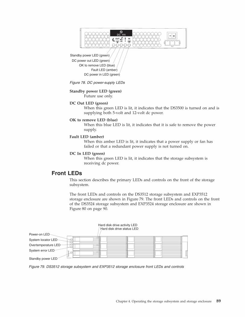
Standby power LED (green)Future use only.
DC Out LED (green)When this green LED is lit, it indicates that the DS3500 is turned on and issupplying both 5-volt and 12-volt dc power.
OK to remove LED (blue)When this blue LED is lit, it indicates that it is safe to remove the powersupply.
Fault LED (amber)When this amber LED is lit, it indicates that a power supply or fan hasfailed or that a redundant power supply is not turned on.
DC In LED (green)When this green LED is lit, it indicates that the storage subsystem isreceiving dc power.
Front LEDsThis section describes the primary LEDs and controls on the front of the storagesubsystem.
The front LEDs and controls on the DS3512 storage subsystem and EXP3512storage enclosure are shown in Figure 79. The front LEDs and controls on the frontof the DS3524 storage subsystem and EXP3524 storage enclosure are shown inFigure 80 on page 90.
Fault LED (amber)DC power in LED (green)
OK to remove LED (blue)
DC power out LED (green)
Standby power LED (green)
Figure 78. DC power-supply LEDs
Hard disk drive activity LED
Power-on LED
System locator LED
System error LED
Overtemperature LED
Standby power LED
Hard disk drive status LED
Figure 79. DS3512 storage subsystem and EXP3512 storage enclosure front LEDs and controls
Chapter 4. Operating the storage subsystem and storage enclosure 89

Power-on LED (green)LED is lit, it indicates that the power supply is turned on and is supplyingboth 5-volt and 12-volt dc power.
System locator LED (blue)This blue LED can be lit by the Storage Manager software to aid invisually locating the storage subsystem.
Overtemperature LED (amber)When this amber LED is lit, it indicates that the storage subsystem is in anover temperature condition.
System error LED (amber)When this amber LED is lit, it indicates that the unit has a fault, such as ina power supply, controller, or drive.
Standby power LED (green)Future use only.
Drive activity LED (green)Each drive has an activity LED. When this green LED is flashing, itindicates drive activity.
Drive status LED (amber)Each drive has a status LED. When this amber LED is lit continuously, itindicates a drive failure. When it is flashing, it indicates that the controlleris identifying or rebuilding an array/disk pool.
Controller LEDsThis section describes the controller LEDs on the rear of the storage subsystem.
Power-on LED
System locator LED
System error LED
Overtemperature LED
Standby power LED
Hard diskdrive statusLED (amber)
Hard diskdrive activityLED (green) d
g1fy
091
Figure 80. DS3524 storage subsystem and EXP3524 storage enclosure front LEDs
90 IBM System Storage DS3500 and EXP3500 Storage Subsystem: Installation, User's, and Maintenance Guide

Ethernet speed LEDWhen this LED is lit, it indicates that the Ethernet speed between thecontroller and the management workstation is 1000 Mbps. When this LEDis off, it indicates that the Ethernet speed is 100 Mbps.
Ethernet activity LEDWhen this LED is lit, it indicates that the link is established between thecontroller and the management workstation. When this LED is flashing,there is activity between the controller and the management workstation.When this LED is off, no link is established between the controller and themanagement workstation.
SAS link service action LED (amber)When this LED is lit, it indicates a problem with the SAS link that requiresservice action. The normal condition of this LED is off.
SAS link up LED (green)When this LED is lit, it indicates that the link is established between thecontroller and a host. When this LED is flashing, it indicates activity on thelink. When this LED is off, no link is established.
Cache active LED (green)When this LED is lit, it indicates that battery backup has been enabled anddata is in the memory cache. When this LED is flashing, cache offload is inprocess. When this LED is off, caching is turned off and no data is in thememory cache.
Fault LED (amber)When this LED is lit, it indicates that a fault has occurred in the controllerand the controller must be replaced. The normal condition of this LED isoff.
OK to remove LED (blue)When this LED is lit, it indicates that it is safe to remove the controllerfrom the DS3500; no activity is taking place, and no data remains in thememory cache. The normal condition of this LED is off.
Battery charging LED (green)When this LED is lit, the battery is fully charged. When this LED isflashing, the battery is charging. When this LED is off, the battery eitherfailed or has been removed from the controller.
Figure 81. Controller LEDs
Chapter 4. Operating the storage subsystem and storage enclosure 91

Battery fault LED (amber)When this LED is lit, it indicates that the battery fails to hold a charge andshould be replaced. The normal condition of this LED is off.
iSCSI activity LED (green)When this LED is lit, it indicates that the link is established with thecontroller. When this LED is flashing, there is activity on this port. Whenthis LED is off, no link is established with this port.
iSCSI speed LED (amber)When this LED is lit, it indicates that the port is operating at 1000 Mbps.When this LED is off, it indicates that the speed of the port is 100 Mbps.
If the optional Fibre Channel host port adapter is installed in the controller, thehost port adapter contains four additional Fibre Channel host connectors withLEDs.
Fibre Channel speed LEDs 2 Gbps and 4 GbpsThese LEDs in combination indicate the speed of the Fibre Channel hostport.
Table 15. Fibre Channel port LEDs
2 Gbps LED 4 Gbps LED Host port speed
On Off 2 Gbps
Off On 4 Gbps
On On 8 Gbps
Off Off No SFP module is present or the SFPmodule is faulty
iSCSIactivityLED
iSCSIspeedLED
Figure 82. iSCSI host port adapter LEDs
Figure 83. Fibre Channel host port adapter LEDs
92 IBM System Storage DS3500 and EXP3500 Storage Subsystem: Installation, User's, and Maintenance Guide
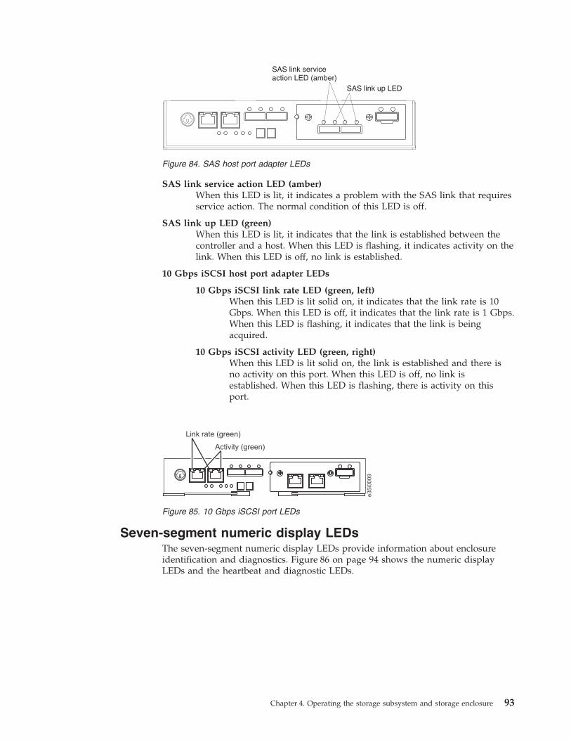
SAS link service action LED (amber)When this LED is lit, it indicates a problem with the SAS link that requiresservice action. The normal condition of this LED is off.
SAS link up LED (green)When this LED is lit, it indicates that the link is established between thecontroller and a host. When this LED is flashing, it indicates activity on thelink. When this LED is off, no link is established.
10 Gbps iSCSI host port adapter LEDs
10 Gbps iSCSI link rate LED (green, left)When this LED is lit solid on, it indicates that the link rate is 10Gbps. When this LED is off, it indicates that the link rate is 1 Gbps.When this LED is flashing, it indicates that the link is beingacquired.
10 Gbps iSCSI activity LED (green, right)When this LED is lit solid on, the link is established and there isno activity on this port. When this LED is off, no link isestablished. When this LED is flashing, there is activity on thisport.
Seven-segment numeric display LEDsThe seven-segment numeric display LEDs provide information about enclosureidentification and diagnostics. Figure 86 on page 94 shows the numeric displayLEDs and the heartbeat and diagnostic LEDs.
SAS link serviceaction (amber)LED
SAS link up LED
Figure 84. SAS host port adapter LEDs
e35i0
009
Activity (green)
Link rate (green)
Figure 85. 10 Gbps iSCSI port LEDs
Chapter 4. Operating the storage subsystem and storage enclosure 93

When you turn on the power to the storage or storage enclosure, the numericdisplay LEDs cycle through various codes as the controller or ESM firmware startsto boot. If the diagnostic LED is illuminated and the heartbeat LED is turned off, itindicates that diagnostic information is displayed on the numeric display. Whenthe controller completes the boot process and is operating normally, the diagnosticLED turns off, the heartbeat LED flashs, and the numeric display changes to showthe enclosure identification (enclosure ID) for that individual enclosure.
If an error occurs during the boot process and the Needs Attention LED is on, thenumeric display shows diagnostic information as sequence of 2-digit diagnosticcode. The number of time each 2-digit code is displayed during a sequence is fixedand under hardware control. Each sequence minimally consists of a two-digitcategory code, followed by a two-digit detail code that is specific to the category.Longer sequences can be displayed if more than one event is to be reported. Thisnominally consists of a series of category-detail sequences with a delimiterbetween each category-detail sequence. The entire display goes blank at the end ofthe sequence (all segments off, the diagnostic light off), and then the sequencerepeats.
For more information about the diagnostic codes and their possible causes, see“Seven-segment display sequence codes and their causes” on page 169.
ESM LEDsThis section describes the ESM LEDS. Figure 87 on page 95 shows the LEDs on theESM.
A
D
BF
CE
G
SSD 1
D
A
EC
FB
G
SSD 2
DP
DP
Diagnostic Light
Heartbeat Light
Lower DigitUpper Digit
dcsi0
038
Figure 86. Numeric display LEDs
94 IBM System Storage DS3500 and EXP3500 Storage Subsystem: Installation, User's, and Maintenance Guide

Link fault LED (amber)When this amber LED is lit, it indicates that the link through the SAS cableis not successful.
Link up LED (green)When this green LED is lit, it indicates that the link through the SAS cableis successful.
OK to remove LED (blue)This LED is supported only when the EXP3500 is attached to a DS3500controller. Do not remove the ESM unless this blue LED is lit.
Fault LED (amber)When this amber LED is lit, it indicates that the ESM has failed.
Power-on LED (green)When this green LED is lit, it indicates that the ESM is receiving power.
Turning off the storage subsystemThe DS3500 is designed to run continuously. After you turn it on, do not turn itoff. Turn off the power only in the following situations:v Instructions in a hardware or software procedure require that you turn off the
power.v An IBM technical-support representative instructs you to turn off the power.v A power outage or emergency situation occurs, see “Restoring power after an
unexpected shutdown” on page 98.
Attention: Except in an emergency, never turn off the power if any amber (needsattention) LEDs are lit. Correct the fault before you turn off the power. Use theStorage Manager software and the amber LEDs to check the overall status of theDS3500. All LEDs should be green on the front of the storage subsystem. If theyare not, use the Storage Manager software to diagnose the problem so that theDS3500 will power-on correctly later.
(L003)
1 2
ESM
Link fault LED(amber)
Link up LED(green)
OK to remove LED(blue) Fault LED
(amber)
Power-on LED(green)
Link fault LED(amber)
Link up LED(green)
Seven-segmentnumeric display
Figure 87. ESM LEDs
Chapter 4. Operating the storage subsystem and storage enclosure 95
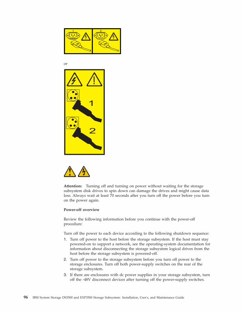
1 2
or
!
1
2
Attention: Turning off and turning on power without waiting for the storagesubsystem disk drives to spin down can damage the drives and might cause dataloss. Always wait at least 70 seconds after you turn off the power before you turnon the power again.
Power-off overview
Review the following information before you continue with the power-offprocedure:
Turn off the power to each device according to the following shutdown sequence:1. Turn off power to the host before the storage subsystem. If the host must stay
powered-on to support a network, see the operating-system documentation forinformation about disconnecting the storage subsystem logical drives from thehost before the storage subsystem is powered-off.
2. Turn off power to the storage subsystem before you turn off power to thestorage enclosures. Turn off both power-supply switches on the rear of thestorage subsystem.
3. If there are enclosures with dc power supplies in your storage subsystem, turnoff the -48V disconnect devices after turning off the power-supply switches.
96 IBM System Storage DS3500 and EXP3500 Storage Subsystem: Installation, User's, and Maintenance Guide
4. Turn off power to other supporting devices (for example, managementstations).
Note: You do not have to perform this step if you are servicing only thestorage subsystem.
To turn off power to one or more storage subsystems for a planned shutdown,complete the steps in the following procedure. To turn off power for an unplannedshutdown, see “Restoring power after an unexpected shutdown” on page 98.Figure 75 on page 84 shows the locations of the power switches on a storagesubsystem.
Before you proceed, use the Storage Manager software to determine the status ofthe system components and special instructions. The operating-system softwaremight require you to perform other procedures before you turn off the power.1. Stop all I/O activity to each storage subsystem.2. Determine the status of all storage subsystems and components in the
configuration by completing the following steps:a. Check all LEDs on each component in the storage enclosures. Ensure that
all the LEDs show normal status.b. Check all LEDs on each component in the storage subsystem. Ensure that
all the LEDs show normal status.c. Review the status of the configuration in the Subsystem Management
window by clicking the Summary tab.The status is either Optimal or Needs Attention.
3. Do the LEDs indicate normal operation, and is the status Optimal on allconfiguration components?v Yes: Go to step 5.v No: Go to step 4.
4. To diagnose and correct the fault, complete the following steps:a. Run the Recovery Guru by clicking Recovery Guru in the toolbar in the
Subsystem Management window.b. Complete the recovery procedure.
If the Recovery Guru directs you to replace a failed component, use theindividual LEDs to locate the failed component.
c. When the recovery procedure is completed, click Recheck in the RecoveryGuru. This action runs the Recovery Guru again to make sure that theproblem is corrected.
d. If the problem has not been corrected, contact your IBM technical-supportrepresentative. Do not turn off power until all problems are corrected.
5. Check the cache active LED, and ensure that it is offIf the cache active LED is lit, the cache contains data. Wait for the data to clearfrom cache memory before you turn off the power.
6. Check the LEDs on the storage enclosures to ensure that all drive activityLEDs are off.If one or more LEDs are flashing, data is being written to or from the drives.Wait for all activity LEDs to stop flashing.
7. Turn off the ac power switch on the rear of each controller in the storagesubsystem.
Chapter 4. Operating the storage subsystem and storage enclosure 97
Note: Until the power switch on each controller is turned off, power remainsturned on for both controllers.
8. Turn off both power switches on the rear of each storage enclosure in theconfiguration.
9. If there are enclosures with dc power supplies in your configuration, turn offthe -48V disconnect devices after turning off the power-supply switches.
10. After you perform the necessary maintenance procedures, turn on the power,using the procedure in “Turning on the storage subsystem” on page 82.
Performing an emergency shutdownAttention: Emergency situations might include fire, flood, extreme weatherconditions, or other hazardous circumstances. If a power outage or emergencysituation occurs, always turn off all power switches on all computing equipment.This helps to safeguard your equipment from potential damage due to electricalsurges when power is restored. If the storage subsystem loses power unexpectedly,it might be due to a hardware failure in the power system or in the midplane.
To shut down the system during an emergency, complete the following steps:1. If you have time, stop all I/O activity to the storage subsystem by shutting
down the host or disconnecting the storage subsystem logical drives throughthe host.
2. Check the LEDs. Make note of any amber LEDs that are lit so that you cancorrect the problem when you turn on the power again.
3. Turn off all power-supply switches, starting with the storage subsystem firstand followed by the storage enclosures. Then, disconnect the power cables fromthe storage subsystem.
4. If there are enclosures with dc power supplies in your storage subsystem, turnoff the -48V disconnect devices after turning off the power-supply switches.
Restoring power after an unexpected shutdownTo restore power to the storage subsystem in a configuration after an unplannedshutdown, complete the following steps.
DANGER
Never turn on any equipment when there is evidence of fire, water, orstructural damage.
1. After the emergency situation is over or power is restored, visually check thestorage subsystem for damage. Is there evidence of damage to any of thestorage subsystem components, cables, or equipment that is attached to thestorage subsystem?v Yes: Do not continue with this procedure. Contact your IBM
technical-support representative for assistance. Depending on the currentservice agreements, you might have to return the equipment to the factory orlocal service center for repair.
v No: Go to step 2 on page 99.
98 IBM System Storage DS3500 and EXP3500 Storage Subsystem: Installation, User's, and Maintenance Guide

Attention: To avoid potential data loss, ensure that the storage subsystemand storage enclosure power switches are turned off before you reset circuitbreakers in the rack. Resetting circuit breakers after an emergency situationwhile the storage subsystem and storage enclosure power switches areturned on can cause data loss, because the configuration components mightnot be powered-on in the correct sequence. See “Turning on the storagesubsystem” on page 82 for details about the correct power-on sequence.
2. After you check the storage subsystem for damage, ensure that the powerswitches are off; then connect the DS3500 power cables, if required.
3. Check the system documentation of the hardware devices that you want toturn on and determine the correct startup sequence.Be sure to turn on all of the storage enclosures and make sure that no ESM orpower-supply fault LEDs are lit before you turn on the storage subsystem.In addition, consider the following items:v The storage subsystem supports simultaneous power-on of the system
components; however, always check the system documentation of thehardware devices that you want to turn on and determine the correct startupsequence.
v A storage subsystem in an optimal state recovers automatically from anunexpected shutdown and unattended simultaneous restoration of power tosystem components. After power is restored, contact your IBMtechnical-support representative if any of the following conditions occur:– The storage subsystem logical drives and subsystems are not displayed in
the Storage Manager graphical user interface.– The storage subsystem logical drives and subsystems do not come online.– The storage subsystem logical drives and subsystems seem to be
degraded.4. Turn on the power to each device, according to the startup sequence.5. If there are enclosures with dc power supplies in your storage subsystem, turn
on the -48V disconnect devices before turning on the power-supply switches.6. Turn on both of the power-supply switches on the DS3500. The green LEDs on
the front and the rear of the DS3500 should remain lit. If other amber LEDs arelit, see Chapter 6, “Solving problems,” on page 161.
Recovering from an overheated power supplyEach storage subsystem contains two power supplies. Each power supply containsa built-in temperature sensor to prevent the power supply from overheating.Under normal operating conditions, with an ambient air temperature range of 10°Cto 40°C (50°F to 104°F), the fans in the power supplies maintain a suitableoperating temperature inside the module.
If the internal temperature reaches 65°C (149°F), the power supply shuts downautomatically. If both power supplies shut down because of overheating, thestorage subsystem has no power, and all LEDs are off.
The following factors can cause the power supplies to overheat:v An unusually high room temperaturev Fan failures in the power suppliesv Defective circuitry in a power supplyv Blocked air ventsv Failures in other devices in the configuration or rack
Chapter 4. Operating the storage subsystem and storage enclosure 99
If a fan failure causes overheating, the system-error LED and overtemperatureLEDs on the storage subsystem are lit. The fault LED on the power supply mightalso be lit. “Checking the LEDs” on page 88 shows the location of the LEDs on theDS3500.
If the storage subsystem temperature exceeds 45°C (113°F), the storagemanagement software displays a Needs Attention icon in the SubsystemManagement window. If the air temperature inside the rack reaches 65°C (149°F),the power supplies automatically shut down. If event monitoring is enabled andevent notification is configured, the software issues two critical-problemnotifications.v If one power supply shuts down, the storage management software displays a
Needs Attention status in the Subsystem Management window.v If both power supplies shut down, the storage subsystem shuts down, and the
storage management software displays a Not Responding status in theSubsystem Management window.Attention: To prevent damage to the storage subsystem components when thepower supplies automatically shut down, immediately remove all rack panels tohelp reduce the rack air temperature.
To resume normal operation after a power-supply shutdown, complete thefollowing steps:1. Did you use the procedure “Troubleshooting the storage subsystem” on page
87 to identify an overheating problem?v Yes: Go to step 2.v No: Perform the procedure in “Troubleshooting the storage subsystem” on
page 87 to ensure that the power supplies have shut down because of anoverheating problem, and then go to step 2.
2. Stop I/O activity to the storage subsystem and all attached storage enclosures.3. Take all or some of the following measures to alleviate the overheating
problem:v Remove all panels from the rack immediately.v Use external fans to cool the area.v Shut down the power to the storage enclosure, using the procedure that is
described in “Performing an emergency shutdown” on page 98.4. Wait for the air in and around the storage subsystem to cool.
After the temperature inside the power supplies drops to below 65°C (149°F),the storage subsystem is capable of power-on recovery without operatorintervention. After the air has cooled, the power supplies should turn onautomatically. If the power supplies restart automatically, the controllers willreset and return to normal operation.
5. Did the power supplies restart automatically?v Yes: Go to step 8 on page 101.v No: Go to step 6.
6. Turn off both power switches on the DS3500 (see Figure 75 on page 84) andthen power-off all connected storage enclosures. Wait 1 minute and then turnon power to all connected storage enclosures.While a storage enclosure powers-on, the LEDs on the front and the rear ofthe enclosure flash intermittently. Depending on your configuration, thestorage enclosure can take between 20 seconds and several minutes topower-on.
100 IBM System Storage DS3500 and EXP3500 Storage Subsystem: Installation, User's, and Maintenance Guide
Note: If there are enclosures with dc power supplies in your storagesubsystem, ensure that the -48V disconnect devices are turned on and areworking.
7. Turn on both power switches on the rear of the storage subsystem. SeeFigure 75 on page 84A storage subsystem can take 10 seconds to power-on and up to 15 minutesfor the battery self-test to be completed. During this time, the LEDs on thefront and the rear of the DS3500 flash intermittently.
8. Check the LEDs on the front and rear of the storage subsystem and eachattached storage enclosure (a green LED indicates a normal status; an amberLED indicates a hardware fault); then, check the subsystem status in theSubsystem Management window.a. Open the Subsystem Management window for the storage subsystem.b. Click the Summary tab and review the status of the configuration.
The status is either Optimal or Needs Attention.9. Does each module (controller, power supply, ESM) display green status LEDs
only, and is the status Optimal for each module component?v Yes: Go to step 11.v No: Go to step 10.
10. Diagnose and correct the fault.a. To run the Recovery Guru, click Recovery Guru in the toolbar in the
Subsystem Management window.b. Complete the recovery procedure.
If the Recovery Guru directs you to replace a failed component, locate andtroubleshoot that component. See “Checking the LEDs” on page 88.
c. When the procedure is completed, select Recheck in the Recovery Guru.This runs the Recovery Guru again to ensure that the problem is corrected.
d. If the problem remains, contact your IBM technical-support representative.11. Replace the bezel on the storage enclosure, if applicable.
Cache memory and cache batteryEach storage controller in the DS3500 storage subsystem contains 1 GB or 2 GB ofcache memory to store read and write operations. In a dual controllerconfiguration, both controllers in the DS3500 must have the same amount of cachememory. The battery unit contains enough charge to back up the cached data ineach controller to a flash drive in the event of a DS3500 power failure.
Cache memoryCache memory is memory on the storage controller that is used for intermediatestorage of read and write data on the DS3500 controllers. Using cache memory canincrease system performance. The data for a read operation from the host might bein the cache memory from a previous operation (thus eliminating the need toaccess the drive itself), and a write operation is completed when it is written to thecache, rather than to the drives.
The controller has a cache active LED that indicates the current status of the cache.The LED is lit when there is data in the cache, and it is off when there is no datain the cache.
Chapter 4. Operating the storage subsystem and storage enclosure 101

If caching is enabled and the cache active LED is not lit during I/O activity, itindicates one of the following conditions:v The cache memory from either controller A or controller B has failedv The cache sizes in controller A and controller B are not the samev The battery has failed
Note: Always use the Storage Manager client to check the cache memory settingsbefore you assume that a hardware failure has occurred.
See “Controller LEDs” on page 90 for the location of the cache active LED on acontroller.
Controller cache batteryThe backup battery unit provides power to back up the cache memory of eachcontroller onto flash drives in the event of a power failure. Each battery unitcontains a sealed, rechargeable SMART lithium ion battery.
CAUTION:The battery is a lithium ion battery. To avoid possible explosion, do not burn.Exchange only with the IBM-approved part. Recycle or discard the battery asinstructed by local regulations. In the United States, IBM has a process for thecollection of this battery. For information, call 1-800-426-4333. Have the IBM partnumber for the battery unit available when you call. (C007)
Replace the battery units in the DS3500 when they are identified as failing by theStorage Manager Subsystem Management window, or when the battery fault LEDslight. See “Controller LEDs” on page 90 for the location of the battery fault LED.
Replace only the battery unit that is indicated as failed by the LEDs or in theStorage Manager Subsystem Management window. In a dual controllerconfiguration, you do not need to replace both battery units when the Battery faultLEDs indicate that only one battery unit has failed. Each controller has a greenBattery charging LED that indicates the status of the battery unit.v The LED is on when the battery is fully chargedv The LED flashes when the battery is charging or performing a self-testv The LED is off when the battery or the battery charger has failed or is missing
Cache battery learn cycleThe battery performs a learn cycle the first time the storage subsystem is turnedon, and again every eight weeks thereafter, to assess the charge capacity of thebattery. If the battery fails the learn cycle or takes too much time to reach fullcharge, the Battery charging LED turns off, the Battery fault LED turns on and theStorage Manager identifies the battery as failed.
The learn cycle takes up to three hours. During this time, the cache will be active ifthe battery is in optimal condition. If the learn cycle is interrupted, the currentlearn cycle will be terminated and the battery will perform a new learn cycle at thenext scheduled interval (eight weeks from the current learn cycle). A learn cycle
102 IBM System Storage DS3500 and EXP3500 Storage Subsystem: Installation, User's, and Maintenance Guide

interruption is caused by removing the battery from the controller chassis, resettingthe power to the storage subsystem, or if a storage enclosure or battery overheats.
Data caching starts after the battery is charged to the programmed voltage level,which occurs when the storage subsystem power is first turned on, when a newbattery is installed to replace a failed battery, or when the subsystem power isturned on after months of inactivity.
Attention: Write caching is suspended while a battery pack is either charging orself-testing.
Chapter 4. Operating the storage subsystem and storage enclosure 103

104 IBM System Storage DS3500 and EXP3500 Storage Subsystem: Installation, User's, and Maintenance Guide

Chapter 5. Replacing components
This section contains information about replacing the storage subsystem andstorage enclosure components and installing optional devices.
Attention: To avoid overheating the storage enclosure and causing damage to itscomponents, replace failed parts within 10 minutes. The Recovery Guru in theStorage Manager software identifies failed parts.
Do not remove the failed part from the storage enclosure until you:v Review the replacement procedure for the failed part in this guide.v Locate screw drivers or any other hand tools that you might need to replace the
failed part.v Receive the replacement part and are ready to install it in the enclosure.
OK to remove LEDThis section describes the different indications of the OK to remove LED.
Before you begin, ensure that you wear an anti-static wrist strap.
Each controller, ESM, and power supply has a blue OK to remove LED. Thepurpose of the OK to remove LED is to help ensure that a component is notremoved before it is safe to do so. Do not remove any component unless thecomponent OK to remove LED is lit.
Attention
If you remove a controller, ESM, or power supply when the OK to remove LED isnot lit, a loss of data availability can result. If an amber LED is lit and theassociated OK to remove LED is not lit, you must perform additional diagnosticsbefore you can remove the indicated component. Use the Recovery Guruinstructions in the Subsystem Management window or see the applicablecomponent replacement instructions in this section for the additional diagnosticsthat are required in this case.
The OK to remove LED automatically turns on or off as conditions change. Wait atleast 2 minutes after you replace a component for the storage subsystem torecognize the new component and update the LED status. In most cases, when asingle component fails, the OK to remove LED stays lit when the amber LED is litfor the component.
Working with controllersThis section describes how to remove a controller, remove and install a cover,install a controller, replace a controller, and dispose of the system-board battery onthe controller.
Before you begin, ensure that you wear an anti-static wrist strap.
© Copyright IBM Corp. 2010, 2013 105
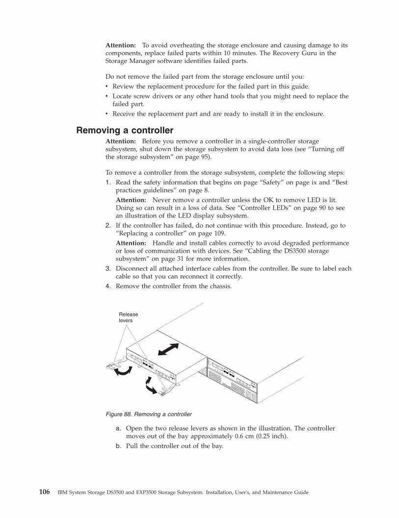
Attention: To avoid overheating the storage enclosure and causing damage to itscomponents, replace failed parts within 10 minutes. The Recovery Guru in theStorage Manager software identifies failed parts.
Do not remove the failed part from the storage enclosure until you:v Review the replacement procedure for the failed part in this guide.v Locate screw drivers or any other hand tools that you might need to replace the
failed part.v Receive the replacement part and are ready to install it in the enclosure.
Removing a controllerAttention: Before you remove a controller in a single-controller storagesubsystem, shut down the storage subsystem to avoid data loss (see “Turning offthe storage subsystem” on page 95).
To remove a controller from the storage subsystem, complete the following steps:1. Read the safety information that begins on page “Safety” on page ix and “Best
practices guidelines” on page 8.Attention: Never remove a controller unless the OK to remove LED is lit.Doing so can result in a loss of data. See “Controller LEDs” on page 90 to seean illustration of the LED display subsystem.
2. If the controller has failed, do not continue with this procedure. Instead, go to“Replacing a controller” on page 109.Attention: Handle and install cables correctly to avoid degraded performanceor loss of communication with devices. See “Cabling the DS3500 storagesubsystem” on page 31 for more information.
3. Disconnect all attached interface cables from the controller. Be sure to label eachcable so that you can reconnect it correctly.
4. Remove the controller from the chassis.
a. Open the two release levers as shown in the illustration. The controllermoves out of the bay approximately 0.6 cm (0.25 inch).
b. Pull the controller out of the bay.
Releaselevers
Figure 88. Removing a controller
106 IBM System Storage DS3500 and EXP3500 Storage Subsystem: Installation, User's, and Maintenance Guide

DANGER
Electrical voltage and current from power cables are hazardous. Toavoid a shock hazard, always place electrical equipment on dry,static-free level surfaces. Never turn on any electrical equipment whenthere is evidence of fire, water, or structural damage.
c. Place the controller on a dry, static-free level surface.
Attention: After you remove a controller, wait 70 seconds before you reseat orreplace the controller. Failure to do so might cause unpredictable results.
Removing and installing a coverTo remove a cover from a controller, complete the following steps:1. Read the safety information that begins on page “Safety” on page ix and “Best
practices guidelines” on page 8.2. Press on the two release buttons and slide the cover toward the rear of the
controller.
3. Remove the cover and save it for future use.
To install a cover on a controller, complete the following steps:1. Read the safety information that begins on page “Safety” on page ix and “Best
practices guidelines” on page 8.2. Align the cover on the controller and slide it toward the front of the controller
to install it.
Installing a controllerUse this procedure to install a second controller. The second controller is controllerB. If the storage subsystem contains only one controller, that controller is controllerA.
Attention: Ensure that the two controllers have the same host port adapter,DIMM size, and options. An incompatible controller will be placed in a lockoutstate by the other controller.
Releasebuttons
Figure 89. Removing the cover
Chapter 5. Replacing components 107

To install a controller in the storage subsystem, complete the following steps:1. Read the safety information that begins on page “Safety” on page ix and “Best
practices guidelines” on page 8.2. Remove the existing storage subsystem using IBM System Storage DS Storage
Manager.3. Install new dual-controller NVSRAM firmware on controller A. For
instructions to download the NVSRAM firmware, see the IBM System StorageDS Storage Manager Version 10 Installation and Host Support Guide (for DSStorage Manager V10.77 or earlier) or the IBM System Storage DS StorageManager Version 10.8 Installation and Host Support Guide (for DS StorageManager V10.83 or later).
Note: Obtain the latest dual-controller NVSRAM firmware fromhttp://www.ibm.com/servers/storage/support/disk/.
4. Start the command-line interface; then, enter the following command tochange controller A from simplex (single-controller) mode to duplex(dual-controller) mode:Smcli ctlr_A_IP_address -c "set storageSubsystem redundancyMode=duplex;"
5. Shut down the storage subsystem, and then start it again (see “Turning on thestorage subsystem” on page 82). If controller A was successfully converted toduplex mode, the Recovery Guru reports an alternate controller missingerror message. If the error message is not reported, reinstall the newdual-controller NVSRAM firmware on controller A and repeat steps 4 through5.
6. Unpack the new controller. Save all packing materials in case you have toreturn a controller.
7. Ensure that both controllers have the same host port adapter, DIMM size, andoptions.
8. If controller A contains an optional host port adapter, install an identicaloptional host port adapter in the new controller. See “Installing an optionalhost port adapter or replacing a failed host port adapter” on page 116 forinstructions.
9. Remove the controller filler panel from the bay:a. Open the two release levers. The filler panel moves out of the bay
approximately 0.6 cm (0.25 inch).b. Pull the filler panel out of the bay.c. Place the filler panel in a safe place for future use.
10. Install the new controller.
Note: The following illustration shows installing controller A. Be sure toinstall the new controller in the rightmost bay, as controller B.
108 IBM System Storage DS3500 and EXP3500 Storage Subsystem: Installation, User's, and Maintenance Guide
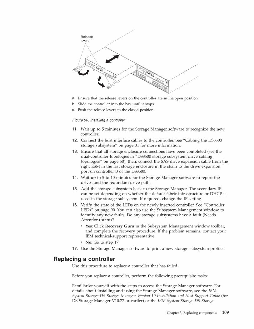
11. Wait up to 5 minutes for the Storage Manager software to recognize the newcontroller.
12. Connect the host interface cables to the controller. See “Cabling the DS3500storage subsystem” on page 31 for more information.
13. Ensure that all storage enclosure connections have been completed (see thedual-controller topologies in “DS3500 storage subsystem drive cablingtopologies” on page 50); then, connect the SAS drive expansion cable from theright ESM in the last storage enclosure in the chain to the drive expansionport on controller B of the DS3500.
14. Wait up to 5 to 10 minutes for the Storage Manager software to report thedrives and the redundant drive path.
15. Add the storage subsystem back to the Storage Manager. The secondary IPcan be set depending on whether the default fabric infrastructure or DHCP isused in the storage subsystem. If required, change the IP setting.
16. Verify the state of the LEDs on the newly inserted controller. See “ControllerLEDs” on page 90. You can also use the Subsystem Management window toidentify any new faults. Do any storage subsystems have a fault (NeedsAttention) status?v Yes: Click Recovery Guru in the Subsystem Management window toolbar,
and complete the recovery procedure. If the problem remains, contact yourIBM technical-support representative.
v No: Go to step 17.17. Use the Storage Manager software to print a new storage subsystem profile.
Replacing a controllerUse this procedure to replace a controller that has failed.
Before you replace a controller, perform the following prerequisite tasks:
Familiarize yourself with the steps to access the Storage Manager software. Fordetails about installing and using the Storage Manager software, see the IBMSystem Storage DS Storage Manager Version 10 Installation and Host Support Guide (forDS Storage Manager V10.77 or earlier) or the IBM System Storage DS Storage
Releaselevers
a. Ensure that the release levers on the controller are in the open position.
b. Slide the controller into the bay until it stops.
c. Push the release levers to the closed position.
Figure 90. Installing a controller
Chapter 5. Replacing components 109
Manager Version 10.8 Installation and Host Support Guide (for DS Storage ManagerV10.83 or later) for the applicable host operating system. The document is in theDocumentation folder on the IBM System Storage DS3500 Support DVD.
Important:
Obtain the following information about your storage subsystem and components:v Determine whether you have a single-controller storage subsystem or a
dual-controller storage subsystem. For details, see “DS3500 storage subsystemoverview” on page 2. See Figure 7 on page 13 for an illustration of asingle-controller storage subsystem.
v See the topic “Checking the LEDs” on page 88 to understand how to check thestatus lights on the LED panel.
v Check the MAC addresses of the host ports after replacing the controller and/orthe host port interface adapter. If you need to change the MAC address, updatethe servers or switches in the configuration.
Attention:
v Ensure that both power supplies are connected and powered-on and no amberLEDs are lit. If the status of either of the power supplies is not Optimal, replacethat power supply before you proceed with the controller replacementprocedure.
v If you are replacing a failed controller, you need to determine the capacity of theDIMM it contains. There are two methods to determine the capacity of theDIMM in a failed controller:– When you remove the failed controller you can look at the label on the
DIMM to see if it is a 1 GB or 2 GB DIMM.– Use the Storage Manager Client. You can view the controller cache size either
on the controller properties screen (found in the Physical tab) or by viewingthe storage subsystems profile. Refer to the IBM System Storage DS StorageManager 10 Installation and Host Support Guide for your host operating system,for guidance on how to install the Storage Manager Client program, and tomake Management connections to the Storage subsystems after its installation.Also, refer to the illustrations for reference.
To replace a controller in a storage subsystem, complete the following steps:1. Read the safety information that begins on page “Safety” on page ix and “Best
practices guidelines” on page 8. See “Checking the LEDs” on page 88 for anillustration of the LED panel.
2. Use the Storage Manager software to print a storage subsystem profile. SeeChapter 4, “Operating the storage subsystem and storage enclosure,” on page81 for more information.v In a dual-controller storage subsystem, move the logical drive ownership to
the other controller.v If the controller that you are replacing is still operating, move the failed
controller to the offline state.
Attention: Never remove a controller unless the OK to remove LED is lit.Doing so can result in a loss of data.
3. Locate the failed controller by checking the amber LEDs on the controllers inthe storage subsystem.
110 IBM System Storage DS3500 and EXP3500 Storage Subsystem: Installation, User's, and Maintenance Guide

4. If you have a single controller storage subsystem, skip this step and go to step5. For a dual controller storage subsystem, follow these instructions:v Is the OK TO REMOVE LED lit? If Yes, go to step 5v If No, another component might require attention before you can remove
the controller. Run the Storage Manager Recovery Guru to identify andcorrect any additional failures. To open Recovery Guru, click the Supporttab in the Subsystem Management window. See “Troubleshooting thestorage subsystem” on page 87 topic for information about using theRecovery Guru.If there are no additional failures, proceed with step 5 to replace thecontroller.
Attention: Static electricity can damage the storage subsystem and otherelectronic devices. To avoid damage, keep static-sensitive devices in theirstatic-protective packages until you are ready to install them.
5. Unpack the new controller. Save all packing materials in case you have toreturn the new controller.
6. Determine whether the replacement controller will be controller A orcontroller B (controller A is installed in the left controller bay; controller B isinstalled in the right controller bay), and then apply the controller labels forhost ports and drive expansion ports to the replacement controller. In asingle-controller storage subsystem, the new controller will go into the sameslot, as the old one. The controller labels and instructions are included withthe replacement controller. Ensure that the labels are aligned correctly and donot cover any connectors or LEDs.Attention: Handle and install cables correctly to avoid degradedperformance or loss of communication with devices. See “Cabling the DS3500storage subsystem” on page 31 for more information.
7. Disconnect all attached interface cables from the failed controller. Ensure thatyou label each cable so that you can reconnect it correctly to the newcontroller.
8. In a single-controller storage subsystem, shut down the storage subsystem (see“Turning off the storage subsystem” on page 95 for the correct sequence ofsteps). See Figure 7 on page 13 for an example of a single-controller StorageSubsystem.
9. Remove the controller from the chassis.
Releaselevers
Figure 91. Removing and replacing a controller
Chapter 5. Replacing components 111

a. Open the two release levers as shown in the illustration. The controllermoves out of the bay approximately 0.6 cm (0.25 inch).
b. Pull the controller out of the bay.DANGER
Electrical voltage and current from power cables are hazardous. Toavoid a shock hazard, always place electrical equipment on dry,static-free level surfaces. Never turn on any electrical equipmentwhen there is evidence of fire, water, or structural damage.
c. Place the controller on a dry, static-free level surface.
Attention: The DS3500 replacement controller ships with a temporary filler.Place the temporary filler in the controller chassis bay after the failedcontroller is removed, to maintain proper airflow and cooling.
10. Remove the cover (see “Removing and installing a cover” on page 107).11. Remove the battery from the failed controller.
a. Loosen the blue captive fastener till you can move the battery in thedirection that is indicated by the arrow.
b. Slide the battery unit out of the controller in the direction that is indicatedby the arrow.
c. Set the battery aside.12. Remove the cache backup flash memory device from the controller and install
in the new controller.a. Release the flash memory device by gently pushing the memory farther
into the slot. The slot will release the flash memory device and push theflash memory device out of the slot.
b. Carefully pull the flash memory device free from the slot.c. Install the cache battery backup flash memory device into the empty slot
location of the new controller by pressing the flash memory device into theslot until the flash memory is fully seated.
The following figure shows the location of the cache backup flash memorydevice on the controller board.
Battery connector
Captive fastener
Memory cache battery
Figure 92. Removing the battery unit from the controller
112 IBM System Storage DS3500 and EXP3500 Storage Subsystem: Installation, User's, and Maintenance Guide

13. If the capacity of the DIMM in the controller that you removed is more than1024 MB, complete the following steps to transfer the DIMM to the newcontroller:a. Remove the 1024 MB DIMM from the new controller and set it aside (see
“Replacing the memory cache DIMM” on page 150 for instructions).b. Insert the DIMM into the new controller (see “Installing the DIMM” on
page 152 for instructions).14. Install the battery from step 11 on page 112 into the new controller:
a. Slide the battery into the controller until the connector pins of the batteryare firmly affixed to the battery connector of the controller.
b. Turn the captive fastener clockwise to secure the battery in place.15. Install the cover (see “Removing and installing a cover” on page 107)
Attention: Remove the temporary filler before you install the replacementcontroller.
16. Install the new controller.a. Ensure that the release levers on the controller are in the OPEN position.b. Slide the controller into the bay until it stops.c. Push the release levers to the CLOSED position.
17. Connect the cables that you disconnected in step 7 on page 111.18. (Single-controller only) Turn on the storage subsystem (see “Turning on the
storage subsystem” on page 82).
dcsi0
015
Cache backupflash memorydevice
Figure 93. Cache backup flash memory device
Chapter 5. Replacing components 113

19. Wait up to 5 minutes for the Storage Manager software to detect the newcontroller.
20. Complete any remaining RECOVERY GURU procedures for controllerreplacement.
21. Check the LEDs on the new controller to ensure that the controller is fullyoperational.
22. Use the Subsystem Management window to check the status of allcomponents in the storage subsystem.v If the new controller is online and the Subsystem Management window
indicates normal operation, go to step 25.v If the new controller is online and the Subsystem Management window
indicates a problem status, go to “Troubleshooting the storage subsystem”on page 87.
v If the new controller is offline, continue with step 23.23. If the newly inserted controller is in an offline state, see the Storage Manager
online help for instructions on bringing the controller online. If necessary,open the Subsystem Management window and place the controller online;select the offline controller and click Advanced > Recovery > Place controlleronline.
24. Verify the state of the LEDs on the newly inserted controller. See “ControllerLEDs” on page 90. You can also use the Subsystem Management window toidentify any new faults. Do any storage subsystems have a fault (NeedsAttention) status?v Yes: Click Recovery Guru in the Subsystem Management window toolbar,
and complete the recovery procedure. If the problem remains, contact yourIBM technical-support representative.
v No: Go to step 25.25. Use the Storage Manager software to print a new storage subsystem profile.26. Check the WWIDs or the MAC addresses of the host ports after replacing the
controller and/or the host port interface adapter. If you need to change anyWWID or MAC address, update the servers or switches in the configuration.
27. You may have to reboot your system to remove LUNs information associatedwith the WWID of the controller you removed.
Removing and disposing of the system-board lithium batteryWhen you disassemble the storage subsystem for disposal, use the information inthis section to locate, remove, and dispose of the lithium batteries that are on thesystem boards in controller A and controller B.
Statement 2
CAUTION:When replacing the lithium battery, use only an equivalent type batteryrecommended by the manufacturer. If your system has a module containing alithium battery, replace it only with the same module type made by the samemanufacturer. The battery contains lithium and can explode if not properly used,handled, or disposed of.
114 IBM System Storage DS3500 and EXP3500 Storage Subsystem: Installation, User's, and Maintenance Guide
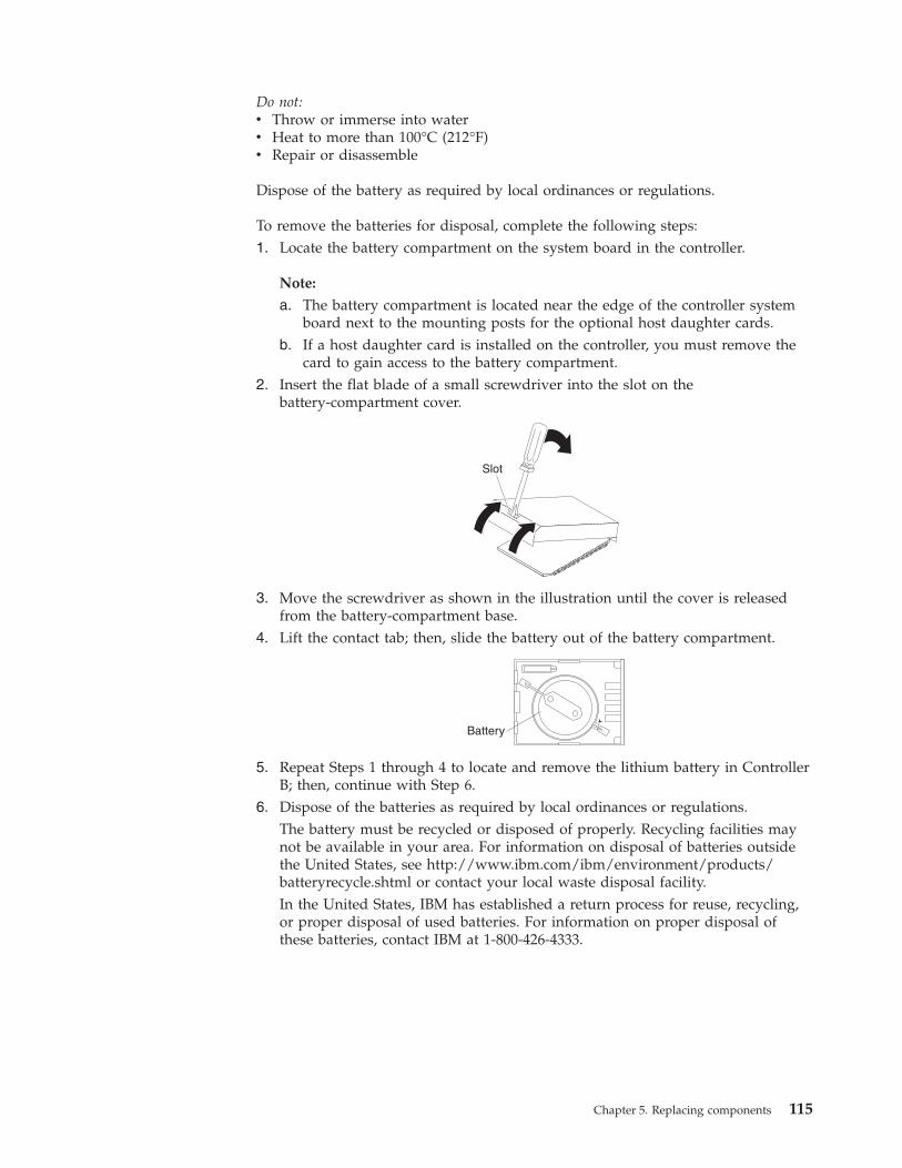
Do not:v Throw or immerse into waterv Heat to more than 100°C (212°F)v Repair or disassemble
Dispose of the battery as required by local ordinances or regulations.
To remove the batteries for disposal, complete the following steps:1. Locate the battery compartment on the system board in the controller.
Note:
a. The battery compartment is located near the edge of the controller systemboard next to the mounting posts for the optional host daughter cards.
b. If a host daughter card is installed on the controller, you must remove thecard to gain access to the battery compartment.
2. Insert the flat blade of a small screwdriver into the slot on thebattery-compartment cover.
Slot
3. Move the screwdriver as shown in the illustration until the cover is releasedfrom the battery-compartment base.
4. Lift the contact tab; then, slide the battery out of the battery compartment.
Battery
5. Repeat Steps 1 through 4 to locate and remove the lithium battery in ControllerB; then, continue with Step 6.
6. Dispose of the batteries as required by local ordinances or regulations.The battery must be recycled or disposed of properly. Recycling facilities maynot be available in your area. For information on disposal of batteries outsidethe United States, see http://www.ibm.com/ibm/environment/products/batteryrecycle.shtml or contact your local waste disposal facility.In the United States, IBM has established a return process for reuse, recycling,or proper disposal of used batteries. For information on proper disposal ofthese batteries, contact IBM at 1-800-426-4333.
Chapter 5. Replacing components 115
Installing an optional host port adapter or replacing a failed host portadapter
Attention: If you install a host port adapter in a controller and the storagesubsystem contains two controllers, you must ensure that an identical host portadapter is installed in the other controller.
Before you begin, ensure that you wear an anti-static wrist strap.
To install a host port adapter, complete the following steps.
Attention: When you add a host port adapter to an existing configuration thesubsystem must be powered off, and you must schedule maintenance time toperform this task offline. To prevent data loss, you must shut down the storagesubsystem before you remove the controller from the chassis. For the correctshutdown sequence, see “Turning off the storage subsystem” on page 95. However,you do not have to power off the subsystem when replacing a failed host portadapter in a dual controller subsystem.1. Read the safety information that begins on page “Safety” on page ix and “Best
practices guidelines” on page 8.2. If you are replacing a failed host port adapter, skip to the next step.
Otherwise, turn off the storage subsystem (see “Turning off the storagesubsystem” on page 95).
3. Label all of the cables that are connected to the controller, then disconnectthose cables.
4. Remove the controller from the chassis.
116 IBM System Storage DS3500 and EXP3500 Storage Subsystem: Installation, User's, and Maintenance Guide

1. Top Cover Latch Buttons2. HIC Thumbscrews3. Host Interface Card4. HIC Interface Connector5. HIC Subplate6. Zero Insertion Force (ZIF) Socket7. Front Bezel
Figure 94. Sequence of removing controller components
Chapter 5. Replacing components 117

a. Open the two release levers as shown in the illustration. The controllermoves out of the bay approximately 0.6 cm (0.25 inch).
b. Pull the controller out of the bay.DANGER
Electrical voltage and current from power cables are hazardous. Toavoid a shock hazard, always place electrical equipment on dry,static-free level surfaces. Never turn on any electrical equipmentwhen there is evidence of fire, water, or structural damage.
c. Place the controller on a dry, static-free level surface.5. Remove the cover (see “Removing and installing a cover” on page 107).6. If no host port adapter is installed, skip to the next step. Otherwise, release
the four captive thumbscrews that hold the host port adapter to the controllerboard. Then, remove the host port adapter by lift it slightly upward to releaseit from the board connector, and pull it away from the front of the controllermodule.
7. If you are replacing a failed host port adapter, skip to the next step.Otherwise, remove the two screws from the cover plate. Flip the top edge ofthe cover plate outward to release the alignment tab and remove the coverplate from the controller.
Releaselevers
Figure 95. Removing a controller
118 IBM System Storage DS3500 and EXP3500 Storage Subsystem: Installation, User's, and Maintenance Guide

8. Touch the static-protective package that contains the host port adapter to anyunpainted metal surface on the storage subsystem; then, remove the adapterfrom the package.
9. If you are replacing a failed host port adapter, skip to the next step.Otherwise, install the host port cover that comes with the optional host portadapter.a. Place the alignment tab/edge inside the host port cutout.b. Secure the host port cover with two screws.
10. Align the host port adapter as shown in the following illustration. The hostport will protrude slightly from the host port cover. Because the host portcover cutout is a tight fit, you must apply slight pressure to get the portconnectors through the cutout.
Host port adapterfiller panel
Screws
Alignment tab dg1fy
160
Figure 96. Removing the host port adapter filler panel
Chapter 5. Replacing components 119

11. Ensure that the host port adapter connector and the controller board connectorare aligned. Do not force fit, but use slight pressure to press the card in theconnector. Then, tighten the four captive fasteners.
12. Install the cover (see “Removing and installing a cover” on page 107).13. Insert the controller into the chassis.
a. Ensure that the release levers on the controller are in the open position.b. Slide the controller into the bay until it stops.c. Push the release levers to the closed position.
14. Reconnect the cables that you disconnected in step 3 on page 116.15. If you are replacing a failed host port adapter operation in a dual-controller
subsystem, skip to the next step. Otherwise, if a second controller exists,repeat the preceding steps for the second controller beginning with 3 on page116.
16. Turn on the storage subsystem (see “Turning on the storage subsystem” onpage 82).
17. Wait up to 5 minutes for the Storage Manager software to recognize thecontroller.
18. Check the LEDs on the controller to ensure that the controller is fullyoperational.
19. Use the Subsystem Management window to check the status of allcomponents in the storage subsystem.v If the controller is online and the Subsystem Management window indicates
normal operation, go to step 22 on page 121.v If the controller is online and the Subsystem Management window indicates
a problem status, go to “Troubleshooting the storage subsystem” on page87.
v If the controller is offline, continue with step 20.20. If the newly inserted controller is in an offline state, see the Storage Manager
online help for instructions on bringing the controller online. If necessary,
e35i0
015Screws
Figure 97. Installing a host port adapter
120 IBM System Storage DS3500 and EXP3500 Storage Subsystem: Installation, User's, and Maintenance Guide
open the Subsystem Management window and place the controller online;select the offline controller and click Advanced → Recovery → Place controlleronline.
21. Verify the state of the LEDs on the newly inserted controller. See “ControllerLEDs” on page 90. You can also use the Subsystem Management window toidentify any new faults. Do any storage subsystems have a fault (NeedsAttention) status?v Yes: Click Recovery Guru in the Subsystem Management window toolbar,
and complete the recovery procedure. If the problem remains, contact yourIBM technical-support representative.
v No: Go to step 22.22. Use the Storage Manager software to print a new storage subsystem profile.23. Check the WWIDs or the MAC addresses of the host ports after replacing the
controller and/or the host port interface adapter. If you need to change anyWWID or MAC address, update the servers or switches in the configuration.
Working with hot-swap drivesThis section explains how you can increase the storage subsystem capacity byadding more drives or by replacing existing drives with ones that have a largercapacity.
Before you begin, complete the following tasks:v Read the safety information that begins on page “Safety” on page ix and
“Handling static-sensitive devices” on page 27.v Ensure that the current system configuration is working correctly.v Back up all important data before you make changes to data storage devices.v Ensure that you wear an anti-static wrist strap.
Before you install or remove drives, review the following information:v Filler panels: A storage subsystem contains filler panels in the unused drive
bays. Before you install new drives, you must remove these filler panels. Savethe filler panels for future use. For proper cooling and EMC protection, each baymust always contain either a filler panel or a hot-swap drive.
v Drives:
– The DS3500 supports the following drives:- Up to 12 LFF 3.5–inch 6 Gbps SAS or NL SAS drives (DS3512 and
EXP3512)- Up to 24 SFF 2.5–inch 6 Gbps SAS, NL SAS, or SSD drives (DS3524 and
EXP3524)– For optimum performance, never insert a drive into the storage subsystem
without first confirming the drive firmware level. Contact your IBMtechnical-support representative for information about supported drivefirmware levels.
– Use of unsupported drives can cause the storage subsystem to fail.– After you remove a drive, wait 70 seconds before you replace or reseat the
drive to allow the drive to spin down. Failure to do so might causeunpredictable results.
v Drive labels: A label is provided on the front of each drive. Use this label torecord the location information for each drive before you remove it. Be sure tokeep a record of the drives and their corresponding bays. Also, record the
Chapter 5. Replacing components 121

location information in “Hard disk drive locations” on page 183. If you install adrive in the wrong bay, you might lose data.
v Drive LEDs: Each drive enclosure has two associated LEDs, a green activityLED and an amber status LED. These LEDs indicate the status for that drive.The drive LEDs on the DS3512 storage subsystem and EXP3512 storageenclosure are shown in Figure 98. The drive LEDs on the DS3524 storagesubsystem and EXP3524 storage enclosure are shown in Figure 99.
Drive activity LED (green)When this LED flashes, it indicates that there is activity to the drive.
Drive status LED (amber)When this LED flashes, it indicates that the drive has been identified bythe software. When this LED is lit and not flashing, it indicates that thedrive has failed.
v Hot-swap hardware: The storage subsystem contains hardware that enables youto replace a failed drive without turning off the storage subsystem. You cancontinue to operate the storage subsystem while a drive is being removed orinstalled. These drives are known as hot-swap drives.
Removing a hard disk driveTo remove a hot-swap drive, complete the following steps.
Note: The drive comes installed in a drive enclosure. Do not attempt to detach thedrive from the enclosure.
Attention: Handle drives gently and do not stack them. Follow all precautionsfor static-sensitive devices.1. Use “Hard disk drive locations” on page 183 to record the location and identify
the drives. Record this information so that you can replace the drives in thesame bays from which you removed them.
Hard disk drive activity LEDHard disk drive status LED
Figure 98. DS3512 storage subsystem and EXP3512 storage enclosure drive LEDs
Hard diskdrive statusLED (amber)
Hard diskdrive activityLED (green) d
g1fy
171
Figure 99. DS3524 storage subsystem and EXP3524 storage enclosure drive LEDs
122 IBM System Storage DS3500 and EXP3500 Storage Subsystem: Installation, User's, and Maintenance Guide

2. Read the safety information that begins on page “Safety” on page ix and “Bestpractices guidelines” on page 8.Attention: Never remove a drive when its green activity LED is flashing.Remove a drive only when its amber status LED is lit (not flashing), when thedrive is inactive (activity LED is off), or when the storage subsystem is turnedoff.
3. (DS3512 and EXP3512) Remove the drive.
a. Press the latch on the end of the enclosure handle to release it, then pull outthe enclosure handle to the open position.
b. Pull the drive approximately 12 mm (0.5 in.) out of the bay and wait 70seconds to allow the drive to spin down and the storage subsystemcontroller to recognize that a drive is removed from the configuration.
4. (DS3524 and EXP3524) Remove the drive.
Drive tray
Tray handle
Latch
Hard disk drive
Figure 100. Removing a drive from a DS3512 or EXP3512
Chapter 5. Replacing components 123
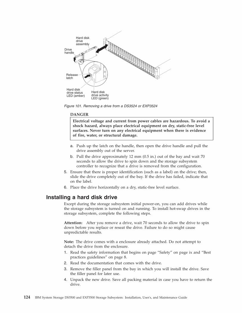
DANGER
Electrical voltage and current from power cables are hazardous. To avoid ashock hazard, always place electrical equipment on dry, static-free levelsurfaces. Never turn on any electrical equipment when there is evidenceof fire, water, or structural damage.
a. Push up the latch on the handle, then open the drive handle and pull thedrive assembly out of the server.
b. Pull the drive approximately 12 mm (0.5 in.) out of the bay and wait 70seconds to allow the drive to spin down and the storage subsystemcontroller to recognize that a drive is removed from the configuration.
5. Ensure that there is proper identification (such as a label) on the drive; then,slide the drive completely out of the bay. If the drive has failed, indicate thaton the label.
6. Place the drive horizontally on a dry, static-free level surface.
Installing a hard disk driveExcept during the storage subsystem initial power-on, you can add drives whilethe storage subsystem is turned on and running. To install hot-swap drives in thestorage subsystem, complete the following steps.
Attention: After you remove a drive, wait 70 seconds to allow the drive to spindown before you replace or reseat the drive. Failure to do so might causeunpredictable results.
Note: The drive comes with a enclosure already attached. Do not attempt todetach the drive from the enclosure.1. Read the safety information that begins on page “Safety” on page ix and “Best
practices guidelines” on page 8.2. Read the documentation that comes with the drive.3. Remove the filler panel from the bay in which you will install the drive. Save
the filler panel for later use.4. Unpack the new drive. Save all packing material in case you have to return the
drive.
System Storage
Hard diskdrive statusLED (amber)
Hard diskdriveassembly
Drivehandle
Releaselatch
Hard diskdrive activityLED (green)
Figure 101. Removing a drive from a DS3524 or EXP3524
124 IBM System Storage DS3500 and EXP3500 Storage Subsystem: Installation, User's, and Maintenance Guide

5. (DS3512 and EXP3512) Install the drive.
a. Press the latch on the end of the drive enclosure handle to release it, thenpull out the enclosure handle to the open position.
b. Slide the drive all the way into the empty bay until the drive stops.c. Push the enclosure handle into the closed (latched) position.
6. (DS3524 and EXP3524) Install the drive.
a. Push up the latch on the handle to release it then, pull out the enclosurehandle to the open position.
b. Slide the drive all the way into the empty bay until the drive stops.c. Push the enclosure handle into the closed (latched) position.
Drive tray
Tray handle
Latch
Hard disk drive
Figure 102. Installing a drive in a DS3512 or EXP3512
System Storage
Hard diskdrive statusLED (amber)
Hard diskdriveassembly
Drivehandle
Releaselatch
Hard diskdrive activityLED (green)
Figure 103. Installing a drive in a DS3524 or EXP3524
Chapter 5. Replacing components 125
7. If you are installing additional drives, wait at least 30 seconds before youinstall each drive.
Replacing a hot-swap driveDrive problems include any malfunctions that delay, interrupt, or preventsuccessful I/O activity between the hosts and the drives in the storage subsystem.This includes transmission problems between the host controllers and the drives.This section explains how to replace a failed drive.
Note: If you want to remove a drive that is not in a failed or bypass state, alwaysuse the Storage Manager software either to place the drive in a failed state or toplace the subsystem that is associated with the drive (or drives) in an offline statebefore you remove the drive from the storage subsystem.
Attention: Failure to replace a drive in its correct bay might result in loss of data.If you are replacing a drive that is part of a configured subsystem and logicaldrive, be sure to install the replacement drive in the correct bay. See the hardwareand software documentation that comes with the DS3500 to determine whetherthere are restrictions regarding drive configurations.
To replace a hot-swap drive, complete the following steps:1. Read the safety information that begins on page “Safety” on page ix and “Best
practices guidelines” on page 8.2. Use the Storage Manager software to print a new storage system profile.3. Determine the location of the drive that you want to remove.
Attention: Never hot-swap a drive when its associated green activity LED isflashing. Hot-swap a drive only when its associated amber status LED is lit andnot flashing.
4. Remove the drive (see “Removing a hard disk drive” on page 122).5. Unpack the new drive. Save all packing material in case you have to return the
drive.
Note: Use “Hard disk drive locations” on page 183 to ensure that you replacethe drive into the correct bay.
6. Install the new drive (see “Installing a hard disk drive” on page 124).7. Check the drive LEDs:
v When a drive is ready for use, the green activity LED is lit and the amberstatus LED is off.
v If the amber status LED is lit and is not flashing, remove the drive from theunit and wait 70 seconds; then, install the drive again.
8. Ensure that the drive is shown in the Subsystem Management window.
Note: If you are replacing more than one drive, replace only one drive at a time.
Replacing multiple drivesThis section provides guidelines for upgrading the drives in the storage subsystem.Read the software documentation and this entire section to determine whether youshould use this procedure, use a modified version of this procedure, or use adifferent procedure that is provided by the operating system.
Note:
126 IBM System Storage DS3500 and EXP3500 Storage Subsystem: Installation, User's, and Maintenance Guide
1. Instructions that are provided with the software supersede any instructions andinformation in this document.
2. Use “Hard disk drive locations” on page 183 to ensure that you replace thedrives into the correct bays.
Attention: After you remove a drive, wait 70 seconds to allow the drive to spindown before you replace or reseat the drive. Failure to do so might causeunpredictable results.
There are two methods for upgrading drives:v Replacing all the drives at the same time
This method requires that you back up the data on the affected drives and thenturn off the DS3500 storage subsystem.Attention: Turn off the DS3500 storage subsystem before you turn off theattached storage enclosures.After you replace all the drives, you must reconfigure the new drives andrestore data from backup. See the procedure in “Replacing all drives at the sametime” on page 128.This is the safest way to exchange drives without losing data. However, thismethod might take a long time to complete because of the backup,reconfiguration, and restoration processes. In addition, other users are not ableto use the storage subsystem (or any storage enclosures attached to the storagesubsystem) until you finish the procedure. You must use this method on RAID 0logical drives.
v Replacing the drives one at a time
In this method, you manually fail each drive, replace it, and wait for the systemto restore data to the new drive before you install the next drive. After youinstall the new drives, you can configure them to make the additional drivespace available. See the procedure in “Replacing the drives one at a time” onpage 130.Using this method, you can replace the drives while the storage enclosures andthe DS3500 are running, eliminating the downtime that is required if you replaceall the drives at once. However, this method is more risky because you can losedata if the drive restoration or storage subsystem reconfiguration process fails.In addition, the reconstruction process might take a long time. This methodworks only on redundant logical drives (RAID 1, 3, 5, or 6). You cannot use thismethod with any drives that contains RAID 0 logical drives.Consider backing up your data if you use this method. This safeguards yourdata if the restoration and reconfiguration process fails or the new drivemalfunctions.
The method that you use depends on the following considerations:v Which method most closely matches the recommended drive upgrade procedure
that is provided in the operating-system or storage-management softwaredocumentation.
v Which RAID level is used on the affected drives (RAID 0 requires you to replaceall the drives at the same time).
v How much downtime is acceptable as you swap the drives.v The number of drives in an subsystem. Replacing drives one at a time is better
suited to subsystems that consist of three to five drives. If you have more than10 drives, consider replacing all drives at the same time.
Chapter 5. Replacing components 127

v How much risk of losing data is acceptable. Because the subsystem is in adegraded state during the RAID subsystem reconstruction and copyback processas result of replacing a drive in the subsystem, any new drive failure will causethe subsystem to fail (causing a loss of data availability and even a loss of data).The duration of the reconstruction and copyback process can be quite long,depending on the size of the RAID subsystem.
v How extensively the data will be changed while the subsystem is in a degradedstate during the RAID subsystem reconstruction and copyback process as aresult of replacing a drive in the subsystem. The more extensive the datachanges are, the more work that will have to be performed to restore the data inthe event that the subsystem fails because an additional drive fails while thesubsystem is in a degraded state.
Replacing all drives at the same timeUse this procedure to replace all drives at the same time. You must use thismethod if you are upgrading drives that contain RAID 0 logical drives. All thedata that is currently on the drives is lost when you replace the drives; therefore,you must back up all data that is currently on the drives. This procedure alsorequires you to turn off the storage enclosures and the DS3500, which makes thestorage subsystem (and any attached storage enclosures) inaccessible to otherusers.
Attention: After you remove a drive, wait 70 seconds to allow the drive to spindown before you replace or reseat the drive. Failure to do so might causeunpredictable results.
To replace all the drives at the same time, complete the following steps:1. Read the following information:
v The information in “Replacing multiple drives” on page 126, particularlythe paragraphs that explain the differences between the two possibleupgrade procedures
v The information in the software documentation about drive upgrades andinstallation
v The documentation that comes with the new drivesRead all precautionary notes, kit instructions, and other information. Kitinstructions often contain the most current information about the drives andtheir installation, plus upgrade or servicing procedures. Compare the kitinstructions with this procedure to determine whether you must modify thisprocedure.
2. Use the Storage Manager software to check the status of the DS3500. Correctany problems that are reported.
3. Perform a complete backup of the drives that you are replacing.You need the backup to restore data on the drives later in this procedure.Attention: When you handle static-sensitive devices, take precautions toavoid damage from static electricity. For details about handling static-sensitivedevices, see “Handling static-sensitive devices” on page 27.
128 IBM System Storage DS3500 and EXP3500 Storage Subsystem: Installation, User's, and Maintenance Guide

DANGER
Electrical voltage and current from power cables are hazardous. To avoida shock hazard, always place electrical equipment on dry, static-free levelsurfaces. Never turn on any electrical equipment when there is evidenceof fire, water, or structural damage.
4. Unpack the new drives. Set the drives on a dry, static-free level surface, awayfrom magnetic fields. Save the packing material and documentation in caseyou have to return the drives.
5. Complete the following steps:a. Stop all I/O activity to the storage subsystem and attached storage
enclosures.b. Ensure that all of the green drive activity LEDs on the front of the storage
subsystem (and on all attached storage enclosures) are not flashing.c. Ensure that the green cache active LEDs are off. See “Controller LEDs” on
page 90 for the location of the cache active LEDs.d. If applicable, use the operating-system software to disconnect the storage
subsystem logical drives from the host before you power-off the storagesubsystem.
Attention: To turn off all power to the storage subsystem, you must turn offboth power-supply switches and disconnect both power cords. Use theprocedure in step 6 for the correct shutdown sequence.
6. Turn off the power to each device according to the following shutdownsequence:a. Turn off power to the host before you turn off power to the storage
subsystem. If the host must stay powered-on to support a network, see theoperating-system documentation for information about disconnecting thestorage subsystem logical drives from the host before the storagesubsystem is powered-off.
b. Turn off power to the storage subsystem before you turn off power to thestorage enclosures. Turn off both power-supply switches on the rear of thestorage subsystem.
c. Turn off power to other supporting devices (for example, managementstations or Ethernet switches).
7. Use the procedures in “Replacing a hot-swap drive” on page 126 to removethe drives that you want to replace. Use the procedures in “Installing a harddisk drive” on page 124 to install the new drives in the storage subsystem.
8. After you install all the new drives, check the system documentation for thehardware devices that you intend to power-on, and then determine the correctstartup sequence. Use the following power-on sequence, where applicable:a. Turn on the power to the supporting devices (for example, Ethernet
switches and management stations) before you turn off power to thestorage subsystem.
b. Turn on the storage enclosures before the storage subsystem. Thecontrollers might not recognize the correct configuration if the drives arepowered-on after the storage subsystem. For instructions for powering-onthe storage subsystem, see the storage subsystem documentation.
c. Turn on the power to the storage subsystem; then, restart or turn on thepower to the host.
9. Turn on the power to each device, according to the power-on sequence in step8. To turn on power to the storage subsystem and the storage enclosures, turn
Chapter 5. Replacing components 129
on the power-supply switches on the rear of the storage subsystem. You mustturn on both power-supply switches to take advantage of the redundantpower supplies.
10. Check the green drive activity LEDs and the amber drive fault LEDs abovethe new drives.Ensure that the drive activity LEDs are lit and the drive fault LEDs are off.
Note: The drive fault LEDs might flash intermittently while the drives spinup.v If a drive activity LED is off, the drive might not be installed correctly.
Remove the drive, wait 70 seconds, and then reinstall it.v If the drive fault LED stays lit or the drive activity LED stays off, the new
drive might be faulty. See the Storage Manager software for problemdetermination.
11. Use the Storage Manager software to configure the new drives. See theStorage Manager software online help for detailed instructions.
12. Restore the data from backup to all the drives.
Replacing the drives one at a timeUse this procedure to replace all the drives one at a time. You cannot use thisprocedure on RAID 0 logical drives (use the procedure in “Replacing all drives atthe same time” on page 128).
Note: If hot spares are assigned in the storage subsystem, you might want tounassign the hot spares while you perform this procedure. If you do not,reconstruction might start on the hot spare before you insert the new drive. Thedata on the new drive is still rebuilt, but the process takes longer for each drive.Remember to reassign the hot spares when you are finished with this procedure.
Attention: After you remove a drive, wait 70 seconds to allow the drive to spindown before you replace or reseat the drive. Failure to do so might causeunpredictable results.
To replace the drives one at a time, complete the following steps:1. Read the following information:
v “Replacing multiple drives” on page 126, particularly the paragraphs thatexplain the differences between the two possible upgrade procedures
v Your software documentation about drive upgrades and installationv The documentation that comes with the new drives
Read all precautionary notes, kit instructions, and other information. Kitinstructions often contain the most current information about the drives andtheir installation, plus upgrade or servicing procedures. Compare the kitinstructions with this procedure to determine whether you must modify thisprocedure.
2. Use the Storage Manager software to check the status of the unit. Correct anyproblems that are reported.
3. Back up the data in the subsystems and logical drives that are configured,using the drives that you are replacing.Attention: When you handle static-sensitive devices, take precautions toavoid damage from static electricity. For details about handling static-sensitivedevices, see “Handling static-sensitive devices” on page 27.
130 IBM System Storage DS3500 and EXP3500 Storage Subsystem: Installation, User's, and Maintenance Guide
DANGER
Electrical voltage and current from power cables are hazardous. To avoida shock hazard, always place electrical equipment on dry, static-free levelsurfaces. Never turn on any electrical equipment when there is evidenceof fire, water, or structural damage.
4. Unpack the new drives. Set the drives on a dry, static-free level surface, awayfrom magnetic fields. Save the packing material and documentation in caseyou have to return the drives.
5. Use the Storage Manager software to ensure that the subsystem that wasdefined using these drives is in Optimal (not Degraded) state before youmanually fail the first drive that you want to replace. If the subsystem is in aDegraded state, use the recovery procedures to bring the subsystem into theoptimal state.Ensure that:v You fail only one drivev The software status display shows a Failed status for the applicable drivev The amber drive fault LED (on the front bezel below the drive) is lit
Attention: Removing the wrong drive can cause data loss. Ensure that youremove only the failed drive. A lit drive fault LED indicates the failed drive.
If you remove an active drive accidentally, wait at least 70 seconds and thenreinstall it. Because you have failed two drives in a RAID subsystem, thesubsystem might be marked as failed by the controller. This subsystem willnot be available to the host for I/O. See the Storage Manager software forfurther recovery instructions. Do not attempt to replace any drives until thesubsystem is brought back to Optimal state.
6. Use the procedures in “Replacing a hot-swap drive” on page 126 to removethe failed drive. Use the procedures in “Installing a hard disk drive” on page124 to install the new drives in the storage subsystem.The new drive automatically reconstructs the data after you install it in thedrive bay.During data reconstruction, the amber drive fault LED might be lit for a fewminutes and then turn off when the green drive activity LED begins flashing.A flashing drive activity LED indicates that data reconstruction is in progress.
Note: If the storage subsystem has active hot spares, data might not startcopying to the new drive until the data is reconstructed on the hot spare. Thisincreases the time that is required to complete the procedure.
7. Check the green drive activity LED and the amber drive fault LED on each ofthe new drives.Ensure that the drive activity LEDs are lit and the drive fault LEDs are off.
Note: The drive fault LEDs might flash intermittently while the drives spinup.v If the drive activity LED is off, the drive might not be installed correctly.
Remove the drive, wait 70 seconds, and then reinstall it.v If the drive fault LED stays lit or the drive activity LED stays off, the new
drive might be faulty or might be an uncertified drive. Use the Storage
Chapter 5. Replacing components 131
Manager software for problem determination. In the case of an uncertifieddrive, ensure that the drive options or drive FRU part number is correct forthe storage subsystem.
8. Use the Storage Manager software to monitor the status of the new drive andthe progress of the data reconstruction. Wait for data reconstruction to finish(the drive activity LED stops flashing).
Note: The drive activity LED continues to flash after reconstruction is finishedif there is I/O activity to that drive. In that case, use the host software todetermine whether the data reconstruction is finished.
9. When reconstruction is finished on the new drive, repeat step 5 on page 131through step 8 for each additional drive that you want to install.
10. Use the Storage Manager software to configure the additional space on thenew drives.
Replacing an ac power supply
(L003)
1 2
or
!
1
2
The power supplies are customer replaceable units (CRUs) and do not requirepreventive maintenance. Use only the supported power supplies for the storagesubsystem.
132 IBM System Storage DS3500 and EXP3500 Storage Subsystem: Installation, User's, and Maintenance Guide

Each power supply has a built-in sensor that detects the following conditions:v Over-voltagev Over-currentv Overheated power supply
If any of these conditions occurs, one or both power supplies will shut down. Ifthe power remains off (does not automatically restart), ensure that the environmentis optimal (no overheating has occurred, all electrical receptacles are working, andso on). For more information, see “Restoring power after an unexpectedshutdown” on page 98.
If both power supplies fail or if the power supplies cannot maintain an internaltemperature below 65°C (149°F), the power supplies will automatically shut down(an overtemperature condition). If this occurs, you must cool the storage subsystemand restart it. See “Restoring power after an unexpected shutdown” on page 98.
Attention: The fans in the power supplies draw in fresh air and force out hot air.The power supplies are hot-swappable and redundant; however, if the fans in onepower supply fail, you must replace the entire failed power supply within 72hours to maintain redundancy and optimum cooling. Do not remove the failedpower supply until you have the replacement power supply. When you do removethe failed power supply, be sure to install the second power supply within 10minutes to prevent any overheating due to the interruption to the air flow thatcools the storage subsystem.
Do not run the storage subsystem without adequate ventilation and cooling,because it might cause damage to the internal components and circuitry.
To replace a power supply, complete the following steps.
Attention: To prevent damage to the storage subsystem components fromoverheating, replace a failed power supply within 10 minutes of removal. Ifreplacing it will take longer than 10 minutes, stop all I/O activity to the storagesubsystem and turn off the power until you complete the replacement. Do notremove the failed power supply from the storage enclosure until you:v Review the replacement procedure in this section.v Have the replacement power supply and are ready to install it in the enclosure.
(L001)
1. If necessary, use the Storage Manager software to print a storage systemprofile.
2. Read the safety information that begins on page “Safety” on page ix and “Bestpractices guidelines” on page 8.
Chapter 5. Replacing components 133
3. Did the Recovery Guru direct you to replace a failed power supply?v Yes: Go to step 4.v No: Run the Recovery Guru to identify the failed component, and then go
to step 4.4. Unpack the new power supply. Save all packing material in case you have to
return the failed power supply.
Note: The new power supply comes with an instruction sheet and label sheet.The instruction sheet provides instructions for placing the correct labels on thepower supply to mark the LEDs correctly. The label sheet contains the peel-offlabels that you actually place on the power supply.
5. Using the information on the instruction sheet, place the labels on the powersupply to correctly mark the LEDs.
6. Turn off the power switch on the new unit.7. Check the fault LED to locate the failed power supply. If a fault is detected,
the amber fault LED is lit.8. Ensure that the OK to remove LED is lit. Do not remove the power supply if
the LED is off. For more information about the OK to remove LED, see “OKto remove LED” on page 105.
134 IBM System Storage DS3500 and EXP3500 Storage Subsystem: Installation, User's, and Maintenance Guide

DANGER
When working on or around the system, observe the followingprecautions:
Electrical voltage and current from power, telephone, and communicationcables are hazardous. To avoid a shock hazard:
v Connect power to this unit only with the provided power cord. Do notuse the provided power cord for any other product.
v Do not open or service any power supply assembly.
v Do not connect or disconnect any cables or perform installation,maintenance, or reconfiguration of this product during an electricalstorm.
v The product might be equipped with multiple power cords. To removeall hazardous voltages, disconnect all power cords.
v Connect all power cords to a properly wired and grounded electricaloutlet. Ensure that the outlet supplies proper voltage and phaserotation according to the system rating plate.
v Connect any equipment that will be attached to this product toproperly wired outlets.
v When possible, use one hand only to connect or disconnect signalcables.
v Never turn on any equipment when there is evidence of fire, water, orstructural damage.
v Disconnect the attached power cords, telecommunications systems,networks, and modems before you open the device covers, unlessinstructed otherwise in the installation and configuration procedures.
v Connect and disconnect cables as described in the followingprocedures when installing, moving, or opening covers on this productor attached devices.
To disconnect:
a. Turn off everything (unless instructed otherwise).
b. Remove the power cords from the outlets.
c. Remove the signal cables from the connectors.
d. Remove all cables from the devices.
To connect:
a. Turn off everything (unless instructed otherwise).
b. Attach all cables to the devices.
c. Attach the signal cables to the connectors.
d. Attach the power cords to the outlets.
e. Turn on the devices.
(D005a)
9. Turn off the power switch and disconnect the power cord from the failedpower supply.
10. Remove the power supply from the bay
Chapter 5. Replacing components 135

a. Open the two release levers as shown in the illustration. The controllermoves out of the bay approximately 0.6 cm (0.25 inch).
b. Slide the power supply out of the bay and set it aside.
DANGER
Electrical voltage and current from power cables are hazardous. To avoida shock hazard, always place electrical equipment on dry, static-free levelsurfaces. Never turn on any electrical equipment when there is evidenceof fire, water, or structural damage.
11. Place the replacement power supply on a dry, static-free level surface.12. Ensure that the release levers on the power supply are in the open position.13. Slide the power supply into the bay until it stops.14. Push the release levers to the closed position.15. Connect the power cord and turn on the power.16. Check the power and fault LEDs on the new unit.17. According to the status of the power and fault LEDs, use one of the following
procedures:v The fault LED is lit and the ac and dc power LEDs are off: The new unit
might be installed incorrectly. The power-supply switch might not beturned on. The power cord connector might not be fully inserted into thepower receptacle or the power-supply ac socket. There might not be anypower to the receptacle that the power supply is connected to. The powercord might be faulty. Go to step 18.
v The fault and ac power LEDs are lit but the dc power LED is off: Thepower supply is faulty. Turn off the power switch and contact your IBMtechnical-support representative for a replacement power supply.
v The ac and dc power LEDs are lit but the fault LED is off: Go to step 19on page 137.
18. Perform the following task or tasks to solve the problem:v Ensure that the power switch is turned to the on position.v Ensure that there is power at the ac outlet and no circuit breaker has
tripped.
Power supply
Releaselevers
Figure 104. Replacing a power supply
136 IBM System Storage DS3500 and EXP3500 Storage Subsystem: Installation, User's, and Maintenance Guide

v Ensure that the power cord is working and fully seated into the electricalreceptacle and the power supply ac connector.
v Reinstall the power supply.If these tasks do not solve the problem, contact your IBM technical-supportrepresentative.
19. Complete any remaining Recovery Guru procedures, if needed.20. Check the status of each component in the storage subsystem.21. Are any amber LEDs lit on any of the components?
v Yes : Click Recovery Guru in the Subsystem Management window toolbarand complete the recovery procedure. If a problem is still indicated, contactyour IBM technical-support representative.
v No: Go to step 22.22. Create, save, and print a new storage subsystem profile.
Replacing a dc power supplyStatement 29
CAUTION:This equipment is designed to permit the connection of the earthed conductor ofthe dc supply circuit to the earthing conductor at the equipment. If thisconnection is made, all of the following conditions must be met:
v This equipment shall be connected directly to the dc supply system earthingelectrode conductor or to a bonding jumper from an earthing terminal bar orbus to which the dc supply system earthing electrode conductor is connected.
v This equipment shall be located in the same immediate area (such as, adjacentcabinets) as any other equipment that has a connection between the earthedconductor of the same dc supply circuit and the earthing conductor, and alsothe point of earthing of the dc system. The dc system shall not be earthedelsewhere.
v The dc supply source shall be located within the same premises as thisequipment.
v Switching or disconnecting devices shall not be in the earthed circuitconductor between the dc source and the point of connection of the earthingelectrode conductor.
Statement 34
Chapter 5. Replacing components 137
CAUTION:To reduce the risk of electric shock or energy hazards:
v This equipment must be installed by trained service personnel in arestricted-access location, as defined by the NEC and IEC 60950-1, FirstEdition, The Standard for Safety of Information Technology Equipment.
v Connect the equipment to a reliably grounded safety extra low voltage (SELV)source. An SELV source is a secondary circuit that is designed so that normaland single fault conditions do not cause the voltages to exceed a safe level (60V direct current).
v Incorporate a readily available approved and rated disconnect device in thefield wiring.
v See the specifications in the product documentation for the requiredcircuit-breaker rating for branch circuit overcurrent protection.
v Use copper wire conductors only. See the specifications in the productdocumentation for the required wire size.
v See the specifications in the product documentation for the required torquevalues for the wiring-terminal nuts.
The dc power supplies are customer replaceable units (CRUs) and do not requirepreventive maintenance. Use only the supported dc power supplies for the storagesubsystem.
Each dc power supply has a built-in sensor that detects the following conditions:v Over-voltagev Over-currentv Overheated power supply
If any of these conditions occurs, one or both power supplies will shut down. Ifthe power remains off (does not automatically restart), ensure that the environmentis optimal (no overheating has occurred, the dc power source is working, and soon). For more information, see “Restoring power after an unexpected shutdown”on page 98.
If both dc power supplies fail or if the power supplies cannot maintain an internaltemperature below 65°C (149°F), the power supplies will automatically shut down(an overtemperature condition). If this occurs, you must cool the storage subsystemand restart it. See “Restoring power after an unexpected shutdown” on page 98.
Attention: The fans in the dc power supplies draw in fresh air and force out hotair. The dc power supplies are hot-swappable and redundant; however, if the fansin one power supply fail, you must replace the entire failed power supply within72 hours to maintain redundancy and optimum cooling. Do not remove the failedpower supply until you have the replacement power supply. When you do removethe failed power supply, be sure to install the second power supply within 10minutes to prevent any overheating due to the interruption to the air flow thatcools the storage subsystem.
Do not run the storage subsystem without adequate ventilation and cooling,because it might cause damage to the internal components and circuitry.
Before you begin, ensure that you wear an anti-static wrist strap.
To replace a dc power supply, complete the following steps.
138 IBM System Storage DS3500 and EXP3500 Storage Subsystem: Installation, User's, and Maintenance Guide
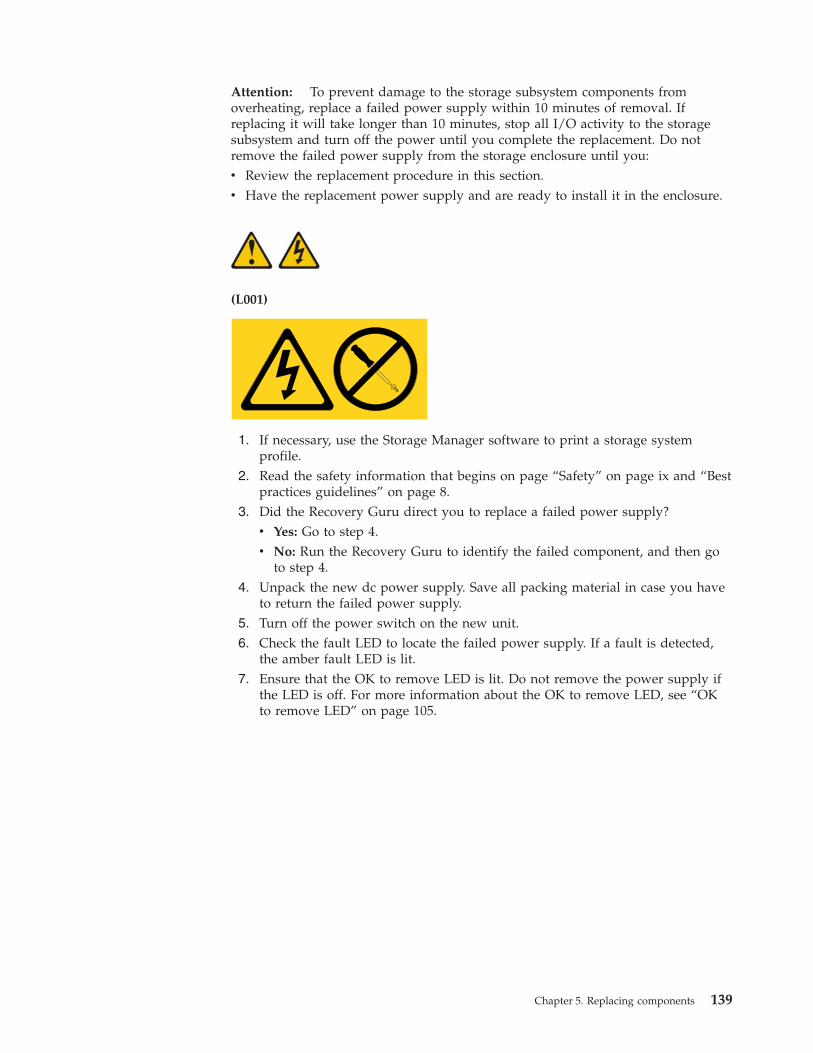
Attention: To prevent damage to the storage subsystem components fromoverheating, replace a failed power supply within 10 minutes of removal. Ifreplacing it will take longer than 10 minutes, stop all I/O activity to the storagesubsystem and turn off the power until you complete the replacement. Do notremove the failed power supply from the storage enclosure until you:v Review the replacement procedure in this section.v Have the replacement power supply and are ready to install it in the enclosure.
(L001)
1. If necessary, use the Storage Manager software to print a storage systemprofile.
2. Read the safety information that begins on page “Safety” on page ix and “Bestpractices guidelines” on page 8.
3. Did the Recovery Guru direct you to replace a failed power supply?v Yes: Go to step 4.v No: Run the Recovery Guru to identify the failed component, and then go
to step 4.4. Unpack the new dc power supply. Save all packing material in case you have
to return the failed power supply.5. Turn off the power switch on the new unit.6. Check the fault LED to locate the failed power supply. If a fault is detected,
the amber fault LED is lit.7. Ensure that the OK to remove LED is lit. Do not remove the power supply if
the LED is off. For more information about the OK to remove LED, see “OKto remove LED” on page 105.
Chapter 5. Replacing components 139
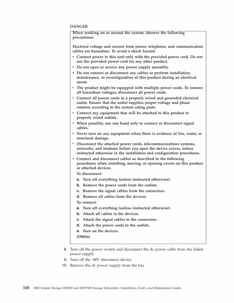
DANGER
When working on or around the system, observe the followingprecautions:
Electrical voltage and current from power, telephone, and communicationcables are hazardous. To avoid a shock hazard:
v Connect power to this unit only with the provided power cord. Do notuse the provided power cord for any other product.
v Do not open or service any power supply assembly.
v Do not connect or disconnect any cables or perform installation,maintenance, or reconfiguration of this product during an electricalstorm.
v The product might be equipped with multiple power cords. To removeall hazardous voltages, disconnect all power cords.
v Connect all power cords to a properly wired and grounded electricaloutlet. Ensure that the outlet supplies proper voltage and phaserotation according to the system rating plate.
v Connect any equipment that will be attached to this product toproperly wired outlets.
v When possible, use one hand only to connect or disconnect signalcables.
v Never turn on any equipment when there is evidence of fire, water, orstructural damage.
v Disconnect the attached power cords, telecommunications systems,networks, and modems before you open the device covers, unlessinstructed otherwise in the installation and configuration procedures.
v Connect and disconnect cables as described in the followingprocedures when installing, moving, or opening covers on this productor attached devices.
To disconnect:
a. Turn off everything (unless instructed otherwise).
b. Remove the power cords from the outlets.
c. Remove the signal cables from the connectors.
d. Remove all cables from the devices.
To connect:
a. Turn off everything (unless instructed otherwise).
b. Attach all cables to the devices.
c. Attach the signal cables to the connectors.
d. Attach the power cords to the outlets.
e. Turn on the devices.
(D005a)
8. Turn off the power switch and disconnect the dc power cable from the failedpower supply.
9. Turn off the -48V disconnect device.10. Remove the dc power supply from the bay
140 IBM System Storage DS3500 and EXP3500 Storage Subsystem: Installation, User's, and Maintenance Guide

a. Open the two release levers as shown in the illustration. The controllermoves out of the bay approximately 0.6 cm (0.25 inch).
b. Slide the dc power supply out of the bay and set it aside.
DANGER
Electrical voltage and current from power cables are hazardous. To avoida shock hazard, always place electrical equipment on dry, static-free levelsurfaces. Never turn on any electrical equipment when there is evidenceof fire, water, or structural damage.
11. Place the replacement dc power supply on a dry, static-free level surface.12. Ensure that the release levers on the power supply are in the open position.13. Slide the dc power supply into the bay until it stops.14. Push the release levers to the closed position.15. Connect the dc power cable and turn on the -48 V disconnect device, then;
turn on the power-supply switch.16. Check the power and fault LEDs on the new unit.17. According to the status of the power and fault LEDs, use one of the following
procedures:v The fault LED is lit and the dc power in and dc power out power LEDs
are off: The new unit might be installed incorrectly. The power-supplyswitch might not be turned on. The dc power cable might not be fullyinserted into the power connector. The disconnect device might be turnedoff or inoperative. The dc power source might be turned off or inoperative.The dc power cable might be faulty. Go to step 18.
v The fault and dc power in LEDs are lit but the dc power out LED is off:The power supply is faulty. Turn off the power switch and contact yourIBM technical-support representative for a replacement power supply.
v The dc power in and dc power out LEDs are lit but the fault LED is off:Go to step 19 on page 142.
18. Perform the following task or tasks to solve the problem:v Ensure that the power switch is turned to the on position.v Ensure that there is power at the dc source and no disconnect device has
tripped.
Power supply
Releaselevers
Figure 105. Replacing a power supply
Chapter 5. Replacing components 141
v Ensure that the power cable is working and fully seated into the dc powerconnector.
v Ensure that the dc power cable is properly connected to the dc powersource.
v Reinstall the power supply.If these tasks do not solve the problem, contact your IBM technical-supportrepresentative.
19. Complete any remaining Recovery Guru procedures, if needed.20. Check the status of each component in the storage subsystem.21. Are any amber LEDs lit on any of the components?
v Yes : Click Recovery Guru in the Subsystem Management window toolbarand complete the recovery procedure. If a problem is still indicated, contactyour IBM technical-support representative.
v No: Go to step 22.22. Create, save, and print a new storage subsystem profile.
Replacing a power-fan controller in the DS3500 controller-driveenclosure
Use one of these procedures to replace a failed power-fan controller in the DS3500controller-drive enclosure. If your storage subsystem uses AC power, use theprocedure on for AC power-fan. If your storage subsystem uses DC power, use theprocedure for DC power-fan.
Replacing an AC power-fan controller in the DS3500controller-drive enclosure
Note: You may refer to “Replacing an ac power supply” on page 132 foradditional information and safety precautions.
Before you begin, gather anti-static protection and a replacement AC power-fancontroller.
Attention: Possible equipment damage – You must replace the power-fancontroller within three minutes after removing the failed power-fan controller toprevent the possibility of overheating the equipment.
You can determine whether you have a failed power-fan controller in two ways:v The Recovery Guru directs you to replace a failed power-fan controller.v You locate the failed power-fan controller by checking the Power-Fan Service
Action Required LED.
Attention: Possible hardware damage – To prevent electrostatic discharge damageto the enclosure, use proper anti-static protection when handling enclosurecomponents.1. If possible, use the storage management software to create, save, and print a
new storage subsystem profile.2. Did the Recovery Guru direct you to replace a failed power-fan controller?
v Yes – Go to step 3.v No – Run the Recovery Guru to identify the failed component, and go to
step 3.
142 IBM System Storage DS3500 and EXP3500 Storage Subsystem: Installation, User's, and Maintenance Guide

3. Put on anti-static protection.4. Unpack the new power-fan controller.
a. Set the new power-fan controller on a flat, static-free surface near thecontroller-drive enclosure.
b. Save all the packing materials in case you need to return the power-fancontroller.
5. Ensure that the Power switch on the new power-fan controller is turned off.6. Check the Power-Fan Service Action Required LEDs on the controller-drive
enclosures to locate the failed power-fan controller.
If a fault is detected, the amber Power-Fan Service Action Required LED is on.If you can safely remove the power-fan controller, the blue Power-Fan ServiceAction Allowed LED is on.CAUTION:Risk of electrical shock – Before removing or installing a power supply,turn off the power switch, and unplug the power cord.
7. Turn off the Power switch on the power-fan controller that has failed.
8. Remove the plastic strain relief from the power cord.9. Unplug the power cord from the failed power-fan controller.
10. Remove the power-fan controller from the controller-drive enclosure.a. Rotate the latches to disengage the power-fan controller.b. Use the latches as handles to pull the power-fan controller out of the
controller-drive enclosure.
Fault LED (amber)AC power LED (green)
OK to remove LED (blue)
DC power LED (green)
Standby power LED (green)
Figure 106. AC power-supply LEDs
Powerswitch
Powerconnector
Powerswitch
Powerconnector
Figure 107. Power-supply switches and connectors for DS3500 AC models
Chapter 5. Replacing components 143

11. Ensure that the Power switch on the replacement power-fan controller isturned off, and plug in the power cord.
12. Slide the replacement power-fan controller all the way into the controller-driveenclosure. Rotate the latches towards the center to lock the power-fancontroller into place.
13. Attach the plastic strain relief to the power cord, and ensure that it fits snuglyup against the power-fan controller.
14. Turn on the Power switch on the new power-fan controller.15. Check the Power-Fan Output DC Power LED, the Power-Fan Input AC Power
LED, and the Power-Fan Service Action Required LED on the new power-fancontroller.
16. Based on the LED status, perform one of these actions:v The Power-Fan Output DC Power LED and the Power-Fan Input AC Power
LED are on and the Power-Fan Service Action Required LED is off – Go tostep 18.
v The Power-Fan Output DC Power LED and the Power-Fan Input AC PowerLED are off or the Power-Fan Service Action Required LED is on – Checkthat the power-fan controller is installed correctly. Reinstall the power-fancontroller. Go to step 17.
17. Did this action correct the problem?v Yes – Go to step 18.v No – If the problem is not resolved, contact your Customer and Technical
Support representative.18. Complete any remaining Recovery Guru procedures, if needed.19. Using the LEDs and the storage management software, check the status of all
of the enclosures in the storage subsystem.20. Does any component have a Needs Attention status?
v Yes – Click the Recovery Guru toolbar button in the SubsystemManagement Window, and complete the recovery procedure. If the problemis not resolved, contact your Customer and Technical Supportrepresentative.
v No – Go to step 21.21. Remove the anti-static protection
Power supply
Releaselevers
Figure 108. Replacing a power supply
144 IBM System Storage DS3500 and EXP3500 Storage Subsystem: Installation, User's, and Maintenance Guide

22. Create, save, and print a new storage subsystem profile.
Replacing a DC power-fan controller in the DS3500controller-drive enclosure
Before you start to replace the power-fan controller in the controller-driveenclosure, gather anti-static protection and a replacement DC power-fan controller.
Attention: Possible equipment damage – You must replace the power-fancontroller within three minutes after removing the failed power-fan controller toprevent the possibility of overheating the equipment.
You can determine whether you have a failed power-fan controller in two ways:v The Recovery Guru directs you to replace a failed power-fan controller.v You locate the failed power-fan controller by checking the Power-Fan Service
Action Required LED.
Attention: Possible hardware damage – To prevent electrostatic discharge damageto the enclosure, use proper anti-static protection when handling enclosurecomponents.1. If possible, use the storage management software to create, save, and print a
new storage subsystem profile.2. Did the Recovery Guru direct you to replace a failed power-fan controller?
v Yes – Go to step 3.v No – Run the Recovery Guru to identify the failed component, and go to
step 3.3. Put on anti-static protection.4. Unpack the new power-fan controller.
a. Set the new power-fan controller on a flat, anti-static surface near thecontroller-drive enclosure.
b. Save all the packing materials in case you need to return the power-fancontroller.
5. Ensure that the Power switch on the new power-fan controller is turned off.6. Check the Power-Fan Service Action Required LEDs on the controller-drive
enclosures to locate the failed power-fan controller.
CAUTION:Risk of electrical shock – Before removing or installing a power supply,turn off the power switch, and unplug the power cord.
Fault LED (amber)DC power in LED (green)
OK to remove LED (blue)
DC power out LED (green)
Standby power LED (green)
Figure 109. DC power-supply LEDs
Chapter 5. Replacing components 145
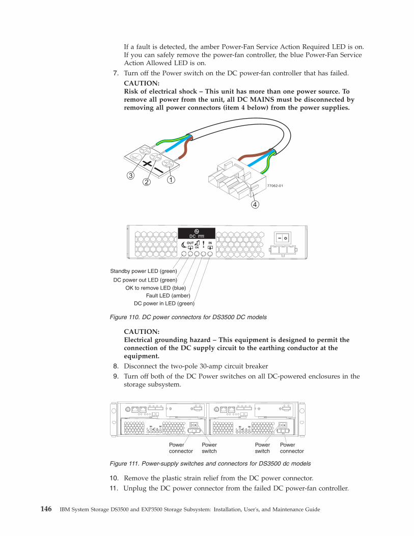
If a fault is detected, the amber Power-Fan Service Action Required LED is on.If you can safely remove the power-fan controller, the blue Power-Fan ServiceAction Allowed LED is on.
7. Turn off the Power switch on the DC power-fan controller that has failed.CAUTION:Risk of electrical shock – This unit has more than one power source. Toremove all power from the unit, all DC MAINS must be disconnected byremoving all power connectors (item 4 below) from the power supplies.
CAUTION:Electrical grounding hazard – This equipment is designed to permit theconnection of the DC supply circuit to the earthing conductor at theequipment.
8. Disconnect the two-pole 30-amp circuit breaker9. Turn off both of the DC Power switches on all DC-powered enclosures in the
storage subsystem.
10. Remove the plastic strain relief from the DC power connector.11. Unplug the DC power connector from the failed DC power-fan controller.
Fault LED (amber)DC power in LED (green)
OK to remove LED (blue)
DC power out LED (green)
Standby power LED (green)
Figure 110. DC power connectors for DS3500 DC models
Powerswitch
Powerconnector
Powerswitch
Powerconnector
Figure 111. Power-supply switches and connectors for DS3500 dc models
146 IBM System Storage DS3500 and EXP3500 Storage Subsystem: Installation, User's, and Maintenance Guide
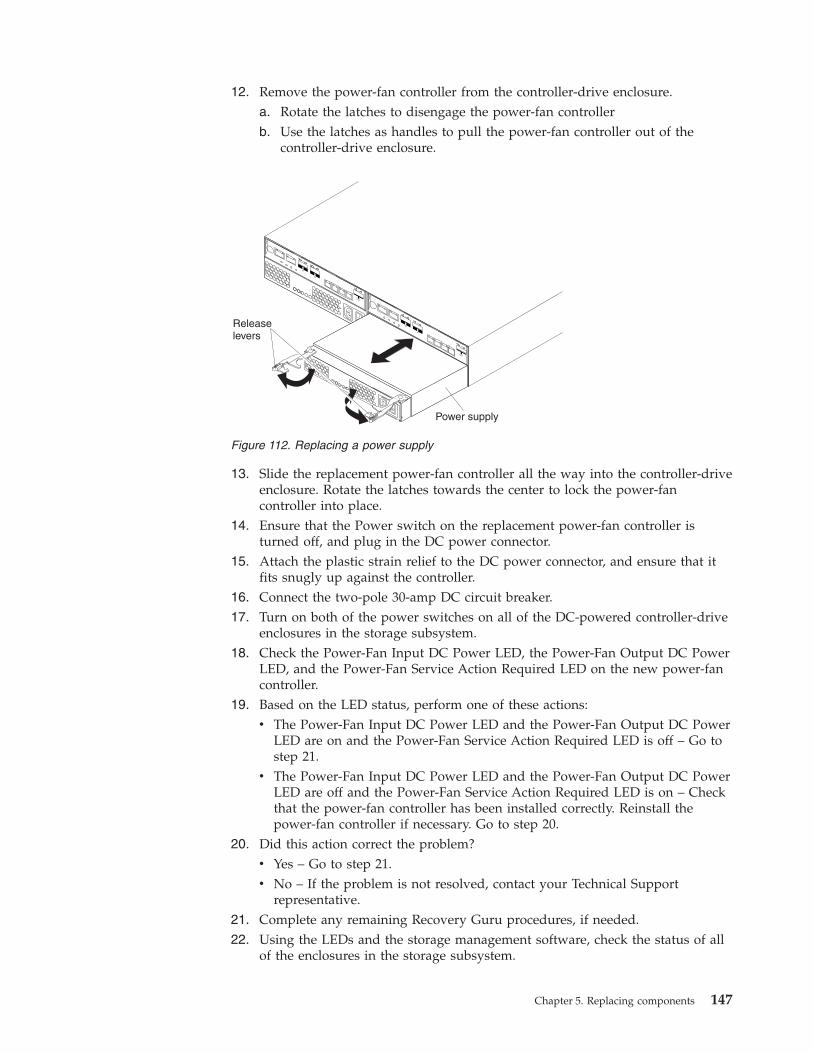
12. Remove the power-fan controller from the controller-drive enclosure.a. Rotate the latches to disengage the power-fan controllerb. Use the latches as handles to pull the power-fan controller out of the
controller-drive enclosure.
13. Slide the replacement power-fan controller all the way into the controller-driveenclosure. Rotate the latches towards the center to lock the power-fancontroller into place.
14. Ensure that the Power switch on the replacement power-fan controller isturned off, and plug in the DC power connector.
15. Attach the plastic strain relief to the DC power connector, and ensure that itfits snugly up against the controller.
16. Connect the two-pole 30-amp DC circuit breaker.17. Turn on both of the power switches on all of the DC-powered controller-drive
enclosures in the storage subsystem.18. Check the Power-Fan Input DC Power LED, the Power-Fan Output DC Power
LED, and the Power-Fan Service Action Required LED on the new power-fancontroller.
19. Based on the LED status, perform one of these actions:v The Power-Fan Input DC Power LED and the Power-Fan Output DC Power
LED are on and the Power-Fan Service Action Required LED is off – Go tostep 21.
v The Power-Fan Input DC Power LED and the Power-Fan Output DC PowerLED are off and the Power-Fan Service Action Required LED is on – Checkthat the power-fan controller has been installed correctly. Reinstall thepower-fan controller if necessary. Go to step 20.
20. Did this action correct the problem?v Yes – Go to step 21.v No – If the problem is not resolved, contact your Technical Support
representative.21. Complete any remaining Recovery Guru procedures, if needed.22. Using the LEDs and the storage management software, check the status of all
of the enclosures in the storage subsystem.
Power supply
Releaselevers
Figure 112. Replacing a power supply
Chapter 5. Replacing components 147

23. Does any component have a Needs Attention status?v Yes – Click the Recovery Guru toolbar button in the Subsystem
Management Window, and complete the recovery procedure. If the problemis not resolved, contact your Technical Support representative.
v No – Go to step 24.24. Remove the anti-static protection.25. Create, save, and print a new storage subsystem profile.
Replacing a batteryThe controller in the storage subsystem contains a rechargeable battery backup unitthat provides power to back up the cache memory onto flash drives in the event ofa power failure. Each battery unit contains a sealed, rechargeable SMART lithiumion battery. The cache battery is the only replaceable battery in the storagesubsystem.
Use the following procedure if the Storage Manager software instructs you toreplace the battery because the current battery has failed. You can also use theStorage Manager software to check the status of the battery. Because write-cachingis disabled when the battery fails, replace the failed battery as soon as possible tominimize any performance impact due to the disabling of the write-cachingfunction.
Attention: When you handle static-sensitive devices, take precautions to avoiddamage from static electricity. For details about handling static-sensitive devices,see “Handling static-sensitive devices” on page 27.
Attention: To avoid overheating the storage enclosure and causing damage to itscomponents, replace failed parts within 10 minutes. The Recovery Guru in theStorage Manager software identifies failed parts.
Do not remove the failed part from the storage enclosure until you:v Review the replacement procedure for the failed part in this guide.v Locate screw drivers or any other hand tools that you might need to replace the
failed part.v Receive the replacement part and are ready to install it in the enclosure.
Before you begin, ensure that you wear an anti-static wrist strap.
To replace a battery unit, complete the following steps:1. Use the Storage Manager software to print a storage subsystem profile.2. Read the safety information that begins on page “Safety” on page ix and “Best
practices guidelines” on page 8.3. Locate the controller that contains the failed battery unit (see “Controller
LEDs” on page 90).Attention: Before you remove a controller in a single-controller DS3500, shutdown the DS3500 to avoid data loss (see “Turning off the storage subsystem”on page 95).
4. Remove the controller from the chassis.
148 IBM System Storage DS3500 and EXP3500 Storage Subsystem: Installation, User's, and Maintenance Guide

a. Open the two release levers as shown in the illustration. The controllermoves out of the bay approximately 0.6 cm (0.25 inch).
b. Pull the controller out of the bay.DANGER
Electrical voltage and current from power cables are hazardous. Toavoid a shock hazard, always place electrical equipment on dry,static-free level surfaces. Never turn on any electrical equipmentwhen there is evidence of fire, water, or structural damage.
c. Place the controller on a dry, static-free level surface.5. Remove the cover (see “Removing and installing a cover” on page 107).6. Place the controller on a flat surface.7. Remove the failed battery unit from the controller.
a. Loosen the blue captive fastener until the battery can move in the directionthat is indicated by the arrow.
b. Slide the battery unit out of the controller in the direction that is indicatedby the arrow.
c. Dispose of the battery as required by local ordinances or regulations. Formore information, see the IBM Systems Environmental Notices and User'sGuide on the IBM Support DVD.
Releaselevers
Figure 113. Removing a controller
Battery connector
Captive fastener
Memory cache battery
Figure 114. Removing a battery unit from the controller
Chapter 5. Replacing components 149
DANGER
Electrical voltage and current from power cables are hazardous. To avoida shock hazard, always place electrical equipment on dry, static-free levelsurfaces. Never turn on any electrical equipment when there is evidenceof fire, water, or structural damage.
8. Unpack the new battery unit. Set the new battery unit on a dry, static-freelevel surface.Save all packing materials in case you have to return the new battery unit.
9. Insert the new battery unit into the controller chassis:a. Slide the battery pack into the controller until the battery-pack connector
pins are firmly seated in the controller battery connector.b. Tighten the captive fastener to secure the battery pack in place.
10. Install the cover (see “Removing and installing a cover” on page 107).11. Insert the controller into the chassis.
a. Ensure that the release levers on the controller are in the open position.b. Slide the controller into the bay until it stops.c. Push the release levers to the closed position.
After you replace a controller cache battery, reset the battery age timer. Forinformation about resetting the batter age timer, see the Storage Manager softwareonline help.
Replacing the memory cache DIMMAttention: To avoid damage to the DIMM, you must first remove the memorycache battery and wait the required time period before you install or remove theDIMM. Follow the instructions in this procedure exactly.
Attention: To avoid overheating the storage enclosure and causing damage to itscomponents, replace failed parts within 10 minutes. The Recovery Guru in theStorage Manager software identifies failed parts.
Do not remove the failed part from the storage enclosure until you:v Review the replacement procedure for the failed part in this guide.v Locate screw drivers or any other hand tools that you might need to replace the
failed part.v Receive the replacement part and are ready to install it in the enclosure.
Before you begin, ensure that you wear an anti-static wrist strap.
Use these procedures if you are replacing a failed DIMM or if you are removingand installing the DIMM as directed in “Replacing a controller” on page 109.
The following illustration shows the location of the memory cache DIMM.
150 IBM System Storage DS3500 and EXP3500 Storage Subsystem: Installation, User's, and Maintenance Guide
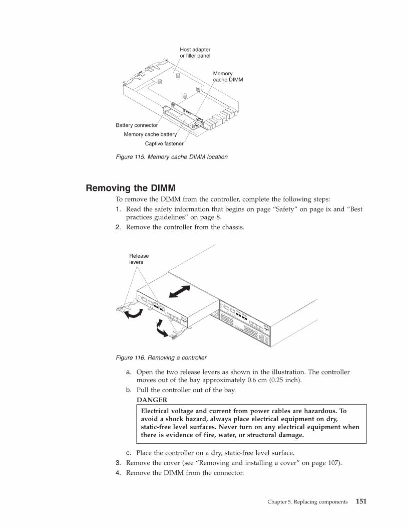
Removing the DIMMTo remove the DIMM from the controller, complete the following steps:1. Read the safety information that begins on page “Safety” on page ix and “Best
practices guidelines” on page 8.2. Remove the controller from the chassis.
a. Open the two release levers as shown in the illustration. The controllermoves out of the bay approximately 0.6 cm (0.25 inch).
b. Pull the controller out of the bay.DANGER
Electrical voltage and current from power cables are hazardous. Toavoid a shock hazard, always place electrical equipment on dry,static-free level surfaces. Never turn on any electrical equipment whenthere is evidence of fire, water, or structural damage.
c. Place the controller on a dry, static-free level surface.3. Remove the cover (see “Removing and installing a cover” on page 107).4. Remove the DIMM from the connector.
Battery connector
Captive fastener
Memory cache battery
Memorycache DIMM
Host adapteror filler panel
Figure 115. Memory cache DIMM location
Releaselevers
Figure 116. Removing a controller
Chapter 5. Replacing components 151
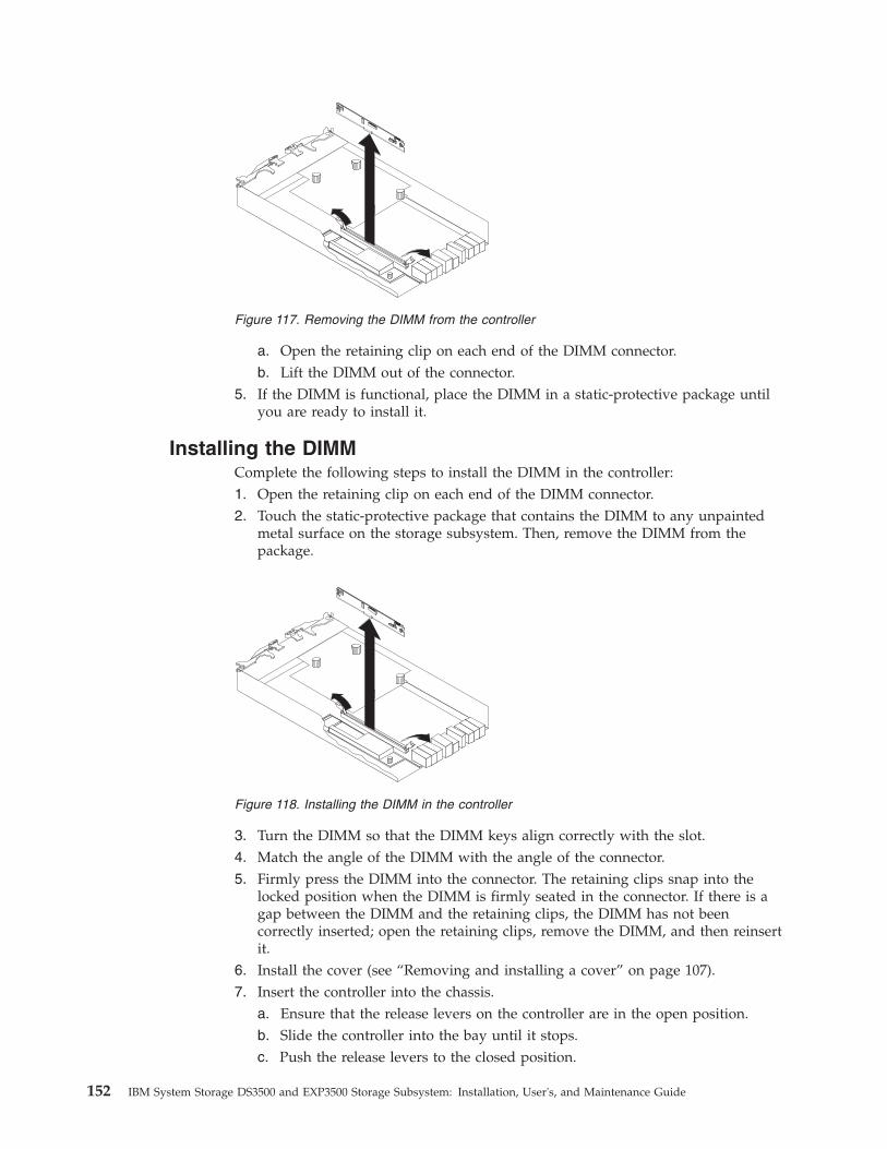
a. Open the retaining clip on each end of the DIMM connector.b. Lift the DIMM out of the connector.
5. If the DIMM is functional, place the DIMM in a static-protective package untilyou are ready to install it.
Installing the DIMMComplete the following steps to install the DIMM in the controller:1. Open the retaining clip on each end of the DIMM connector.2. Touch the static-protective package that contains the DIMM to any unpainted
metal surface on the storage subsystem. Then, remove the DIMM from thepackage.
3. Turn the DIMM so that the DIMM keys align correctly with the slot.4. Match the angle of the DIMM with the angle of the connector.5. Firmly press the DIMM into the connector. The retaining clips snap into the
locked position when the DIMM is firmly seated in the connector. If there is agap between the DIMM and the retaining clips, the DIMM has not beencorrectly inserted; open the retaining clips, remove the DIMM, and then reinsertit.
6. Install the cover (see “Removing and installing a cover” on page 107).7. Insert the controller into the chassis.
a. Ensure that the release levers on the controller are in the open position.b. Slide the controller into the bay until it stops.c. Push the release levers to the closed position.
Figure 117. Removing the DIMM from the controller
Figure 118. Installing the DIMM in the controller
152 IBM System Storage DS3500 and EXP3500 Storage Subsystem: Installation, User's, and Maintenance Guide

Attention: After you remove a controller, wait 70 seconds before you reseat orreplace the controller. Failure to do so might cause unpredictable results.
Turning on the storage subsystem after replacing components
Note: This section talks about turning on the storage subsystem after makingchanges to the hardware. For instructions to turn on the storage subsystem for thefirst time, refer to “Turning on the storage subsystem” on page 82.1. Bring the controller online.
Use either the GUI (first bullet) or the CLI (second bullet) to bring thecontroller online.v In the Subsystem Management Window, right-click the picture of the
controller, and then select Advanced >> Place >> Online.v Select option set controller [(a | b)] availability=online;
v
2. Look at the LEDs on the controller to ensure that the controller is bootingcorrectly.The seven-segment display shows the sequence OS+ Sd+ blank- to indicate thatthe controller is performing Start-of-day (SOD) processing. After the controllersuccessfully completes rebooting, the seven-segment display shows theenclosure ID matching the seven-segment display on the second controller.After this time, you can discover the controller by using the storagemanagement software.
3. Based on the LED status, perform one of these actions:v All of the Service Action Required LEDs are off, and the Subsystem
Management Window indicates an Optimal status – Go to step 5.v Any of the controller-drive enclosure’s Service Action Required LEDs are on,
or the Controller Service Action Required LED is on – Check that thecontroller has been installed correctly. Reinstall the controller if necessary. Goto step 4.
4. Did this action correct the problem?v Yes – Go to step 5.v No – If the problem is not resolved, contact your Technical Support
representative.5. Using the LEDs and the storage management software, check the status of all
of the enclosures in the storage subsystem.6. Does any component have a Needs Attention status?
v Yes – Click the Recovery Guru toolbar button in the Subsystem ManagementWindow, and complete the recovery procedure. If the problem is notresolved, contact your Technical Support representative.
Power-on LED
System locator LED
System error LED
Overtemperature LED
Standby power LED
Hard diskdrive statusLED (amber)
Hard diskdrive activityLED (green) d
g1
fy0
91
Figure 119. DS3524 storage subsystem and EXP3524 storage enclosure front LEDs
Chapter 5. Replacing components 153
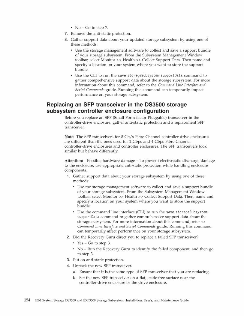
v No – Go to step 7.7. Remove the anti-static protection.8. Gather support data about your updated storage subsystem by using one of
these methods:v Use the storage management software to collect and save a support bundle
of your storage subsystem. From the Subsystem Management Windowtoolbar, select Monitor >> Health >> Collect Support Data. Then name andspecify a location on your system where you want to store the supportbundle.
v Use the CLI to run the save storageSubsystem supportData command togather comprehensive support data about the storage subsystem. For moreinformation about this command, refer to the Command Line Interface andScript Commands guide. Running this command can temporarily impactperformance on your storage subsystem.
Replacing an SFP transceiver in the DS3500 storagesubsystem controller enclosure configuration
Before you replace an SPF (Small Form-factor Pluggable) transceiver in thecontroller-drive enclosure, gather anti-static protection and a replacement SFPtransceiver.
Note: The SFP transceivers for 8-Gb/s Fibre Channel controller-drive enclosuresare different than the ones used for 2 Gbps and 4 Gbps Fibre Channelcontroller-drive enclosures and controller enclosures. The SFP transceivers looksimilar but behave differently.
Attention: Possible hardware damage – To prevent electrostatic discharge damageto the enclosure, use appropriate anti-static protection while handling enclosurecomponents.1. Gather support data about your storage subsystem by using one of these
methods:v Use the storage management software to collect and save a support bundle
of your storage subsystem. From the Subsystem Management Windowtoolbar, select Monitor >> Health >> Collect Support Data. Then, name andspecify a location on your system where you want to store the supportbundle.
v Use the command line interface (CLI) to run the save storageSubsystemsupportData command to gather comprehensive support data about thestorage subsystem. For more information about this command, refer toCommand Line Interface and Script Commands guide. Running this commandcan temporarily affect performance on your storage subsystem.
2. Did the Recovery Guru direct you to replace a failed SFP transceiver?v Yes – Go to step 3.v No – Run the Recovery Guru to identify the failed component, and then go
to step 3.3. Put on anti-static protection.4. Unpack the new SFP transceiver.
a. Ensure that it is the same type of SFP transceiver that you are replacing.b. Set the new SFP transceiver on a flat, static-free surface near the
controller-drive enclosure or the drive enclosure.
154 IBM System Storage DS3500 and EXP3500 Storage Subsystem: Installation, User's, and Maintenance Guide

c. Save all the packing materials in case you need to return the SFPtransceiver.
5. To locate a failed SFP transceiver in the DS3500 controller-drive enclosure,look at the Host Link LEDs on the rear of the controllers. Both Host LinkLEDs for a particular port are off if an SFP transceiver fails.
v If both Host LEDs are off for a particular port – You must replace the SFPtransceiver. Go to step 6.
v If at least one Host LED is on for a particular port – The SFP transceiver isfunctional. The Host LEDs indicate a channel speed of 2 Gbps, 4 Gbps, or 8Gbps.
Attention: Potential degraded performance – To prevent degradedperformance, do not twist, fold, pinch, or step on fiber-optic cables. Do notbend the fiber-optic cables tighter than a 5 CM (2 INCH.) radius.
Note: The Controller Service Action Required LED comes on whenever a lossof a path occurs. The storage management software’s enclosure Componentinformation dialog provides both channel information and port information tohelp you identify the components that are in the path.
6. If it is present, disconnect the fiber-optic cable from the failed SFP transceiver.
7. Remove the failed SFP transceiver from the interface port. Refer to theprocedure for “Removing SFP modules” on page 38
Figure 120. Controller LEDs
SFPmodule
Fiber opticcable
dg1fy
115
Figure 121. Installing an SFP module into the host port
Chapter 5. Replacing components 155

8. Install the new SFP transceiver into the interface port.9. Reconnect the fiber-optic cable.
10. Look at the Host Link LEDs, the Expansion (Drive) LEDs, and the ServiceAction Required LEDs on any controller-drive enclosure.
11. Complete any Recovery Guru procedures, as needed.12. Using the LEDs and the storage management software, check the status of all
of the enclosures in the storage subsystem.13. Does any component have a Needs Attention status?
v Yes – Click the Recovery Guru toolbar button in the SubsystemManagement Window, and complete the recovery procedure. If the problemis not resolved, contact your Technical Support representative.
v No – Go to step 14.14. Remove the anti-static protection.15. Gather support data about your updated storage subsystem by using one of
these methods:v Use the storage management software to collect and save a support bundle
of your storage subsystem. From the Subsystem Management Windowtoolbar, select Monitor >> Health >> Collect Support Data. Then, name andspecify a location on your system where you want to store the supportbundle.
v Use the CLI to run the save storageSubsystem supportData command togather comprehensive support data about the storage subsystem. For moreinformation about this command, refer to Command Line Interface and ScriptCommands. Running this command can temporarily affect performance onyour storage subsystem.
Replacing the bezelsThis section describes how to remove and install the bezels.
Before you begin, ensure that you wear an anti-static wrist strap.
Removing the bezels
To remove either the left or right bezel, complete the following steps:
Right bezel
Left bezel
Handles
Figure 122. Removing the bezels
156 IBM System Storage DS3500 and EXP3500 Storage Subsystem: Installation, User's, and Maintenance Guide

1. If the storage subsystem is on a table or other flat surface, elevate the storagesubsystem front slightly or extend the front over the table edge.
2. Grasp the handle on the front of the bezel and pull until the bezel is clear ofthe bottom tab on the chassis flange.
3. Lift the bezel off the chassis flange.
Installing the bezelsTo install either the left or right bezel, complete the following steps:1. Fit the cutout that is on the top of the bezel over the tab on the chassis flange.2. Rotate the bezel down until it snaps into place. Ensure that the inside surface
of the bezel is flush with the chassis.
Working with environmental service modulesThis section describes how to add or replace an ESM.
Attention: To avoid overheating the storage enclosure and causing damage to itscomponents, replace failed parts within 10 minutes. The Recovery Guru in theStorage Manager software identifies failed parts.
Do not remove the failed part from the storage enclosure until you:v Review the replacement procedure for the failed part in this guide.v Locate screw drivers or any other hand tools that you might need to replace the
failed part.v Receive the replacement part and are ready to install it in the enclosure.
Before you begin, ensure that you wear an anti-static wrist strap.
Installing an additional ESMThe storage enclosure comes with one environmental services module (ESM). Ifyour controller supports redundant drive paths (see the documentation that comeswith the controller or the device that contains the controller), you can install asecond ESM.
To install a second ESM, complete the following steps:1. Read the safety information that begins on page “Safety” on page ix and “Best
practices guidelines” on page 8.2. Remove the ESM filler panel from the rightmost ESM bay:
a. Open the two release levers. The ESM filler panel moves out of the bayapproximately 0.6 cm (0.25 inch).
b. Slide the ESM filler panel out of the bay and set it aside.
DANGER
Electrical voltage and current from power cables are hazardous. To avoid ashock hazard, always place electrical equipment on dry, static-free levelsurfaces. Never turn on any electrical equipment when there is evidence offire, water, or structural damage.
3. Place the ESM on a dry, static-free level surface.4. Ensure that the release levers on the ESM are in the open position.5. Slide the ESM into the bay until it stops.
Chapter 5. Replacing components 157

6. Push the release levers to the closed position.7. Connect the SAS cable or cables to the ESM. See Chapter 3, “Cabling the
storage subsystem and storage enclosure,” on page 31 for more information.
Replacing an ESMIf you are replacing the only ESM in the EXP3500 storage enclosure, you must turnoff power to the storage enclosure before you replace the ESM. See “Turning offthe storage subsystem” on page 95 or see the documentation that comes with yourcontroller for additional information and instructions.
To replace an ESM, complete the following steps:1. Read the safety information that begins on page “Safety” on page ix and “Best
practices guidelines” on page 8.2. If the EXP3500 storage enclosure contains only one ESM, turn off the power to
the storage enclosure. See “Turning off the storage subsystem” on page 95 orsee the documentation that comes with your controller for additionalinformation and instructions.
3. Disconnect the cable from the ESM.4. Open the two release levers. The ESM moves out of the bay approximately 0.6
cm (0.25 inch).
5. Slide the ESM out of the bay and set it aside.6. Ensure that the release levers on the ESM are in the open position.7. Slide the ESM into the bay until it stops.8. Push the release levers to the closed position.9. Connect the cable to the ESM.
10. Turn on the power. For more information, see “Turning on the storagesubsystem” on page 82.
11. Go to http://www.ibm.com/servers/storage/support/ to check for ESM codeupdates. For more information, see the download instructions on page 1.
Releaselevers
ESM
1
2
ESM
Figure 123. Removing an environmental service module
158 IBM System Storage DS3500 and EXP3500 Storage Subsystem: Installation, User's, and Maintenance Guide

Replacing a midplane assemblyThe midplane assembly must be replaced only by a trained service provider.
Before you begin, ensure that you wear an anti-static wrist strap.
To replace the midplane assembly, complete the following steps.
Attention: To prevent data loss, you must shut down the storage subsystem orstorage enclosure before you begin the procedure to replace the midplaneassembly.1. Read the safety information that begins on page “Safety” on page ix and “Best
practices guidelines” on page 8.2. (DS3512 and DS3524) Turn off the storage subsystem (see “Turning off the
storage subsystem” on page 95).3. Remove the drives (see “Removing a hard disk drive” on page 122).4. Remove the power supplies (see “Replacing an ac power supply” on page
132).5. (DS3512 and DS3524) Remove the controllers (see “Removing a controller” on
page 106).6. (EXP3512 and EXP3524) Remove the ESMs (see “Replacing an ESM” on page
158).7. (DS3512 AND EXP3512) Replace the midplane assembly.
a. Loosen the four captive screws at the rear of the chassis.b. Remove the failed midplane from the chassis and insert the replacement
midplane.c. Tighten the four captive screws.
8. (DS3524 AND EXP3524) Replace the midplane assembly.
Midplaneassembly
Captivescrews
Figure 124. Replacing the midplane assembly in a DS3512 or EXP3512
Chapter 5. Replacing components 159

a. Remove the six screws from the sides of the chassis.b. Remove the failed midplane from the chassis and insert the replacement
midplane.c. Secure with the six screws.
9. (EXP3512 and EXP3524) Reinstall the ESMs (see “Replacing an ESM” on page158).
10. (DS3512 and DS3524) Reinstall the controllers (see “Installing a controller” onpage 107).
11. Label the cable connections and disconnect the cables from the enclosure.12. Reinstall the power supplies (see “Replacing an ac power supply” on page
132).13. Reinstall the drives (see “Installing a hard disk drive” on page 124).14. Reconnect the cables to the controllers or the ESMs.15. (DS3512 and DS3524) Turn on the storage subsystem (see “Turning on the
storage subsystem” on page 82).16. Check the LEDs to ensure that the storage subsystem or storage enclosure is
fully operational (see “Checking the LEDs” on page 88).
Figure 125. Replacing the midplane assembly in a DS3524 or EXP3524
160 IBM System Storage DS3500 and EXP3500 Storage Subsystem: Installation, User's, and Maintenance Guide
Chapter 6. Solving problems
This section contains information to help you solve some of the problems that youmight have with the storage subsystem or storage enclosure. It describes theproblem indicators, error messages, and suggested actions.
Solving problems in the DS3500 storage subsystemFor instructions for obtaining service and technical assistance for the storagesubsystem and other IBM products, see Appendix B, “Getting help and technicalassistance,” on page 187.
Use the LEDs, the diagnostics and test information, the symptom-to-FRU index,and the connected server Hardware Maintenance Manual or Problem Determinationand Service Guide to diagnose problems.
Use Table 16 on page 162 and the Storage Manager Recovery Guru to diagnosestorage subsystem problems and component failures and find solutions toproblems that have definite symptoms. Do not depend solely on Table 16 on page162 for a replacement decision.
© Copyright IBM Corp. 2010, 2013 161
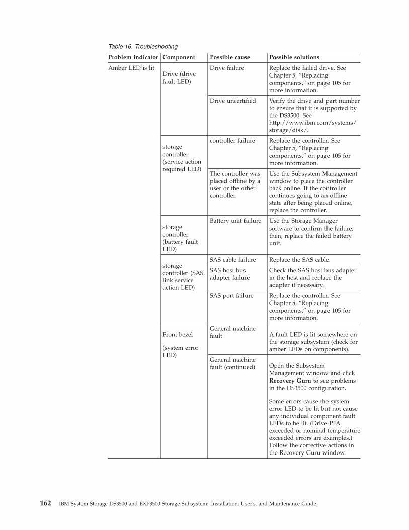
Table 16. Troubleshooting
Problem indicator Component Possible cause Possible solutions
Amber LED is litDrive (drivefault LED)
Drive failure Replace the failed drive. SeeChapter 5, “Replacingcomponents,” on page 105 formore information.
Drive uncertified Verify the drive and part numberto ensure that it is supported bythe DS3500. Seehttp://www.ibm.com/systems/storage/disk/.
storagecontroller(service actionrequired LED)
controller failure Replace the controller. SeeChapter 5, “Replacingcomponents,” on page 105 formore information.
The controller wasplaced offline by auser or the othercontroller.
Use the Subsystem Managementwindow to place the controllerback online. If the controllercontinues going to an offlinestate after being placed online,replace the controller.
storagecontroller(battery faultLED)
Battery unit failure Use the Storage Managersoftware to confirm the failure;then, replace the failed batteryunit.
storagecontroller (SASlink serviceaction LED)
SAS cable failure Replace the SAS cable.
SAS host busadapter failure
Check the SAS host bus adapterin the host and replace theadapter if necessary.
SAS port failure Replace the controller. SeeChapter 5, “Replacingcomponents,” on page 105 formore information.
Front bezel
(system errorLED)
General machinefault A fault LED is lit somewhere on
the storage subsystem (check foramber LEDs on components).
General machinefault (continued) Open the Subsystem
Management window and clickRecovery Guru to see problemsin the DS3500 configuration.
Some errors cause the systemerror LED to be lit but not causeany individual component faultLEDs to be lit. (Drive PFAexceeded or nominal temperatureexceeded errors are examples.)Follow the corrective actions inthe Recovery Guru window.
162 IBM System Storage DS3500 and EXP3500 Storage Subsystem: Installation, User's, and Maintenance Guide

Table 16. Troubleshooting (continued)
Problem indicator Component Possible cause Possible solutions
Amber LED is lit(continued)
storagecontroller faultLED (serviceaction LEDmay also be lit)
Unsupportedcontroller
Controller configurations do notmatch. Check that host daughtercard and cache memory are thesame in both controllers.
Front panel Fibre Channelconnection Check that the CRUs are
properly installed. If no amberLEDs are lit, suspect failure ofthe SFP module. Verify thefailure using the StorageManager Client.
If all Fibre Channel connectionsfailed, suspect failure of the FibreChannel host daughter card.
SAS connectionCheck the SAS connection toverify that the CRUs are properlyinstalled.
If the SAS port LED is off,suspect failure of the SAS hostdaughter card.
iSCSI connectionCheck the iSCSI connection toverify that the CRUs are properlyinstalled.
If the iSCSI port LED is off,check the Ethernet cable or verifythe link speed.
If all the iSCSI port LEDs are off,suspect failure of the iSCSI hostdaughter card.
Battery fault Battery unit failure Verify the failure using theStorage Manager Client andreplace the failed battery.
Amber LED is litand green LED isoff
Power supply
(Amber faultLED is lit andboth powerLEDs are notlit)
The power switch isturned off or thereis an ac or dcpower sourcefailure.
Replace the failed power supplyor turn on all power-supplyswitches. If this is a dc powersupply, check the disconnectdevice to ensure that it isworking and is in the onposition.
Chapter 6. Solving problems 163
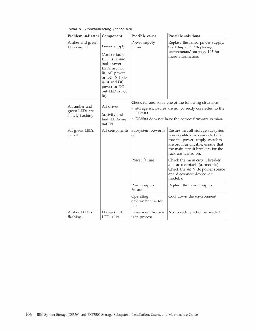
Table 16. Troubleshooting (continued)
Problem indicator Component Possible cause Possible solutions
Amber and greenLEDs are lit Power supply
(Amber faultLED is lit andboth powerLEDs are notlit, AC poweror DC IN LEDis lit and DCpower or DCout LED is notlit)
Power supplyfailure
Replace the failed power supply.See Chapter 5, “Replacingcomponents,” on page 105 formore information.
All amber andgreen LEDs areslowly flashing
All drives
(activity andfault LEDs arenot lit)
Check for and solve one of the following situations:
v storage enclosures are not correctly connected to theDS3500.
v DS3500 does not have the correct firmware version.
All green LEDsare off
All components Subsystem power isoff
Ensure that all storage subsystempower cables are connected andthat the power-supply switchesare on. If applicable, ensure thatthe main circuit breakers for therack are turned on.
Power failure Check the main circuit breakerand ac receptacle (ac models).Check the -48 V dc power sourceand disconnect device (dcmodels).
Power-supplyfailure
Replace the power supply.
Operatingenvironment is toohot
Cool down the environment.
Amber LED isflashing
Drives (faultLED is lit)
Drive identificationis in process
No corrective action is needed.
164 IBM System Storage DS3500 and EXP3500 Storage Subsystem: Installation, User's, and Maintenance Guide

Table 16. Troubleshooting (continued)
Problem indicator Component Possible cause Possible solutions
One or moregreen LEDs areoff
Power supplies Power cable isdisconnected orswitches are turnedoff
Ensure that the power cables areconnected (ac or dc) and that thedisconnect device (dc only) andthe power-supply switches areturned on.
All drives Midplane failure Replace the DS3500. Contactyour IBM technical-supportrepresentative.
Severalcomponents
Hardware failure Replace the affected components.If this does not correct theproblem, replace the controllers.Contact your IBMtechnical-support representative.
The DS3500 was notpowered-on, or allSAS cableconnectionsbetween the storageenclosures and theDS3500 storagesubsystem failed.
Perform one of the followingactions:
v Power-on the storagesubsystem.
v Ensure that the SAS cableconnections between thestorage enclosures and theDS3500 storage subsystem aremade.
Front panel Power supplyproblem
Ensure that the power cables areconnected and that the powersupplies are turned on.
Hardware failure If any other LEDs are lit, replacethe midplane. Contact your IBMtechnical-support representative.
Green LED isflashing slowly(once every 2seconds)
Drives The DS3500 was notpowered-on, or allSAS connectionsbetween the storageenclosures and theDS3500 storagesubsystem havefailed.
Perform one of the followingactions:
v Power-on the storagesubsystem.
v Ensure that the SASconnections between thestorage enclosures and theDS3500 storage subsystem aremade.
v Ensure that all the storageenclosures in the same channelpair have the same enclosurespeed setting.
Chapter 6. Solving problems 165
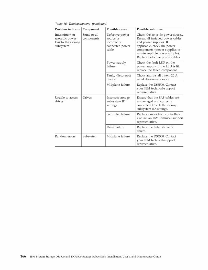
Table 16. Troubleshooting (continued)
Problem indicator Component Possible cause Possible solutions
Intermittent orsporadic powerloss to the storagesubsystem
Some or allcomponents
Defective powersource orincorrectlyconnected powercable
Check the ac or dc power source.Reseat all installed power cablesand power supplies. Ifapplicable, check the powercomponents (power supplies oruninterruptible power supply).Replace defective power cables.
Power supplyfailure
Check the fault LED on thepower supply. If the LED is lit,replace the failed component.
Faulty disconnectdevice
Check and install a new 20 Arated disconnect device.
Midplane failure Replace the DS3500. Contactyour IBM technical-supportrepresentative.
Unable to accessdrives
Drives Incorrect storagesubsystem IDsettings
Ensure that the SAS cables areundamaged and correctlyconnected. Check the storagesubsystem ID settings.
controller failure Replace one or both controllers.Contact an IBM technical-supportrepresentative.
Drive failure Replace the failed drive ordrives.
Random errors Subsystem Midplane failure Replace the DS3500. Contactyour IBM technical-supportrepresentative.
166 IBM System Storage DS3500 and EXP3500 Storage Subsystem: Installation, User's, and Maintenance Guide
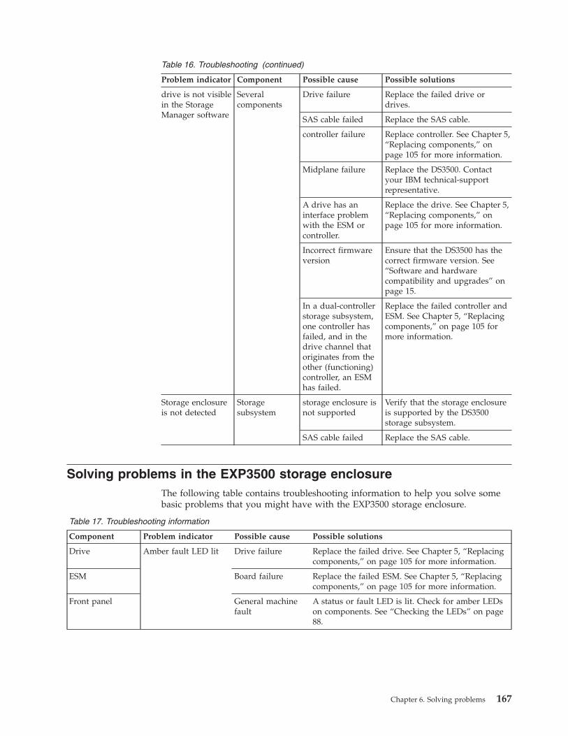
Table 16. Troubleshooting (continued)
Problem indicator Component Possible cause Possible solutions
drive is not visiblein the StorageManager software
Severalcomponents
Drive failure Replace the failed drive ordrives.
SAS cable failed Replace the SAS cable.
controller failure Replace controller. See Chapter 5,“Replacing components,” onpage 105 for more information.
Midplane failure Replace the DS3500. Contactyour IBM technical-supportrepresentative.
A drive has aninterface problemwith the ESM orcontroller.
Replace the drive. See Chapter 5,“Replacing components,” onpage 105 for more information.
Incorrect firmwareversion
Ensure that the DS3500 has thecorrect firmware version. See“Software and hardwarecompatibility and upgrades” onpage 15.
In a dual-controllerstorage subsystem,one controller hasfailed, and in thedrive channel thatoriginates from theother (functioning)controller, an ESMhas failed.
Replace the failed controller andESM. See Chapter 5, “Replacingcomponents,” on page 105 formore information.
Storage enclosureis not detected
Storagesubsystem
storage enclosure isnot supported
Verify that the storage enclosureis supported by the DS3500storage subsystem.
SAS cable failed Replace the SAS cable.
Solving problems in the EXP3500 storage enclosureThe following table contains troubleshooting information to help you solve somebasic problems that you might have with the EXP3500 storage enclosure.
Table 17. Troubleshooting information
Component Problem indicator Possible cause Possible solutions
Drive Amber fault LED lit Drive failure Replace the failed drive. See Chapter 5, “Replacingcomponents,” on page 105 for more information.
ESM Board failure Replace the failed ESM. See Chapter 5, “Replacingcomponents,” on page 105 for more information.
Front panel General machinefault
A status or fault LED is lit. Check for amber LEDson components. See “Checking the LEDs” on page88.
Chapter 6. Solving problems 167

Table 17. Troubleshooting information (continued)
Component Problem indicator Possible cause Possible solutions
All components All green LEDs off The EXP3500 isturned off
Ensure that all power cables are connected and thatthe power is on. If applicable, ensure that the maincircuit breakers for the rack are turned on.
ac or dc powerfailure
Check the main circuit breaker and ac outlet (acmodels). Check the -48 V dc power source anddisconnect device (dc models).
Power-supplyfailure
Replace the power supply. See Chapter 5,“Replacing components,” on page 105 for moreinformation.
Midplane failure Contact your IBM technical-support representative.
Drives Amber fault LEDflashing
Drive rebuild oridentity in process
No action is required.
Power supply -ac
Amber fault LED lit;green dc power LEDoff
Power supplyfailure; powersupply turned off
If the power-supply switch is on, turn off thepower supply and then turn it on again. If thecondition remains, replace the power supply.
Power supply -ac
Amber fault LED lit;green ac power LEDoff
No ac power topower supply
Check the ac power cord or breaker.
v If ac power is good at the source, replace thepower cord.
v If the power supply has failed, replace the powersupply.
Power supply -dc
Amber fault LED lit;green dc power outLED off
Power supplyfailure; powersupply turned off
If the power-supply switch is on, turn off thepower supply and then turn it on again. If thecondition remains, replace the power supply.
Power supply -dc
Amber fault LED lit;green dc power inLED off
No -48 V dc powerto power supply
Check the dc power cable or disconnect device.
v If dc power is good at the source, replace the dcpower cable or the 20 A disconnect device.
v If the dc power cable and the disconnect deviceare working properly, replace the power supply.
ESM Link fault amber LEDlit
SAScommunicationfailure
1. Reconnect the SAS cable.
2. Replace the SAS cable.
3. If the LED is still lit, replace either the ESM orthe controller or device into which the other endof the SAS cable is connected.
One or moredrives
One or more greenLEDs off
No activity to thedrives
No action is required.
All drives No activity to thedrives
No action is required.
Damaged or looseSAS cables
Check the SAS cables and connections.
ESM failure Use the controller management software to checkthe drive status. Replace the ESM.
Midplane failure Contact your IBM technical-support representative.
Front panel Power supply Ensure that the cables are connected and the powersupplies are turned on.
Hardware failure If any other LEDs are lit, contact your IBMtechnical-support representative.
168 IBM System Storage DS3500 and EXP3500 Storage Subsystem: Installation, User's, and Maintenance Guide

Table 17. Troubleshooting information (continued)
Component Problem indicator Possible cause Possible solutions
Some or allcomponents
Intermittent orsporadic power loss
Defective ac or dcpower source orpartially connectedpower cord
1. Check the ac or dc power source.
2. Secure all installed power cables and powersupplies.
3. If applicable, check the power components(power supplies, uninterruptible power supply,and so on).
4. Replace defective power cables.
Power-supplyfailure
Check for a fault LED on the power supply andreplace the failed power supply. See “Checking theLEDs” on page 88.
Midplane failure Contact your IBM technical-support representative.
Drives Unable to access anydrives
SAS cable 1. Ensure that the SAS cables are undamaged andcorrectly connected.
2. Replace the cables.
ESM failure Contact your IBM technical-support representative.
Subsystem Random errors Midplane failure Contact your IBM technical-support representative.
Seven-segment display sequence codes and their causesIf an error occurs during the controller or ESM boot process and the NeedsAttention LED is on, the numeric display shows diagnostic information as asequence of 2-digit diagnostic code. The following figure shows the seven-segmentalphanumeric characters.
Figure 126. Seven-segment alphanumeric characters
Chapter 6. Solving problems 169
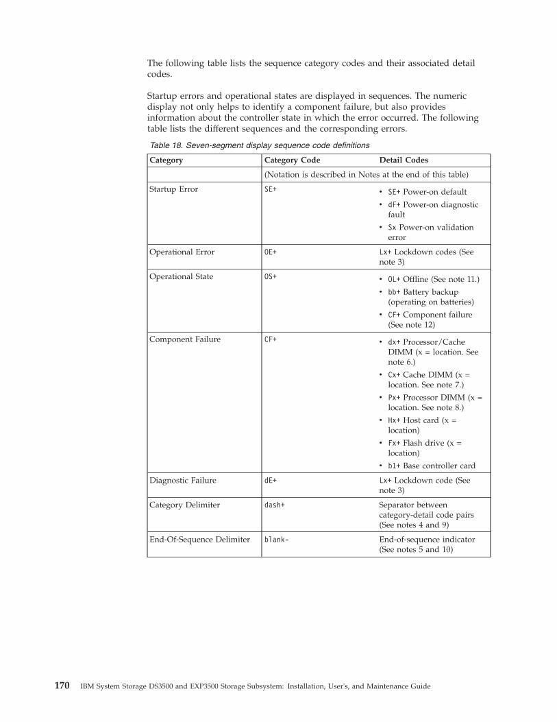
The following table lists the sequence category codes and their associated detailcodes.
Startup errors and operational states are displayed in sequences. The numericdisplay not only helps to identify a component failure, but also providesinformation about the controller state in which the error occurred. The followingtable lists the different sequences and the corresponding errors.
Table 18. Seven-segment display sequence code definitions
Category Category Code Detail Codes
(Notation is described in Notes at the end of this table)
Startup Error SE+ v SE+ Power-on default
v dF+ Power-on diagnosticfault
v Sx Power-on validationerror
Operational Error OE+ Lx+ Lockdown codes (Seenote 3)
Operational State OS+ v OL+ Offline (See note 11.)
v bb+ Battery backup(operating on batteries)
v CF+ Component failure(See note 12)
Component Failure CF+ v dx+ Processor/CacheDIMM (x = location. Seenote 6.)
v Cx+ Cache DIMM (x =location. See note 7.)
v Px+ Processor DIMM (x =location. See note 8.)
v Hx+ Host card (x =location)
v Fx+ Flash drive (x =location)
v b1+ Base controller card
Diagnostic Failure dE+ Lx+ Lockdown code (Seenote 3)
Category Delimiter dash+ Separator betweencategory-detail code pairs(See notes 4 and 9)
End-Of-Sequence Delimiter blank- End-of-sequence indicator(See notes 5 and 10)
170 IBM System Storage DS3500 and EXP3500 Storage Subsystem: Installation, User's, and Maintenance Guide

Table 18. Seven-segment display sequence code definitions (continued)
Category Category Code Detail Codes
Notes:
1. xy+ Indicates that the diagnostic LED is lit.
2. xy- Indicates that the diagnostic LED is turned off.
3. Lx+ Lockdown codes (See Table 20 on page 172)
4. dash+ All segments are off except the middle segments and the diagnostic light is on.
5. blank- All segments are off and the diagnostic light is off.
6. dx+ Used when there is a single memory system for processor and data cache.
7. Cx+ Used when there are separate processor and data cache memory systems.
8. Px+ Used when there are separate processor and data cache memory systems.
9. Category-Detail separator is used when there is more than one category-detail pair inthe sequence. For examples, see Table 19
10. End-of-sequence indicator is automatically inserted by hardware at the end of thesequence. Example: SE+ 88+ blank- (repeat)
11. If an enclosure ID is being displayed, this sequence is programmed to display. Thecontroller is then held in reset.
12. The enclosure ID is nominally displayed during normal operation. This operationalstate is displayed if an internal controller component failure occurs while thecontroller is online. An additional detail code identifies the failed component asdefined for the Component Failure category. This sequence will continue to displayeven if the controller is later placed offline (held in reset) to service the failedcomponent.
Table 19. Repeating sequences on the seven-segment display and corresponding errors
Repeating Sequence Startup and Operational Error
Controller power-on failure:
SE+ 88+ blank- v Initial phase of normal power-oncontroller insertion
v Insertion of a controller while held inreset
Operational failure:
xy- (static controller enclosure ID) Normal operation, where xy is the ID of theenclosure
OS+ Sd+ blank- During start-of-day (SOD) processing that isprocessing when the controller reaches afully powered-up state
OS+ OL+ blank- Controller is placed in reset while displayingthe enclosure ID
OS+ bb+ blank- Controller is operating on batteries (cachebackup)
OS+ OH+ blank- The processor temperature exceeds thewarning level
Component failure when the controller is operational:
OS+ CF+ HX+ blank- The host interface card failed
OS+ CF+ Fx+ blank- The flash drive failed
Power-on diagnostic failure:
SE+ dF+ blank- Failure of a component that is not a fieldreplaceable unit is detected
Chapter 6. Solving problems 171

Table 19. Repeating sequences on the seven-segment display and correspondingerrors (continued)
Repeating Sequence Startup and Operational Error
SE+ dF+ dash+ CF+ dx+ blank- Failure of a processor DIMM or a cachememory DIMM is detected
SE+ dF+ dash+ CF+ Hx+ blank Failure of a host interface card is detected
SE+ LC+ dash+ CF+ Fx+ blank- An incorrect number of cache backupdevices are detected
Controller is suspended and no other errors to report:
OE+ Lu+ blank- All lockdown conditions, where Lu is thelockdown code as shown in the table ofdiagnostic codes
Controller is suspended because of component errors:
OE+ L2+ dash+ CF+ CX+ blank- Persistent processor or cache DIMM ECCerrors are detected
Controller is suspended as a result of persistent cache backup configuration errors:
OE+ LC+ blank- During cache restore, the write-protectswitch is set
OE+ LC+ dd+ blank- The memory size is changed with invaliddata in the flash drives
Controller is suspended as a result of diagnostic errors:
dE+ L2+ dash+ CF+ Cx + blank- A cache memory diagnostic failure isdetected
dE+ L3+ dash+ CF+ b1 + blank- A base controller diagnostic failure isdetected
dE+ L3+ dash+ CF+ b2 + blank- A base controller IOC diagnostic failure isdetected
The following tables list the ESM diagnostic codes.
Table 20. Controller numeric display diagnostic codes
Value Description
L0 Mismatched controller board ID
L1 Missing interconnect controller
L2 Persistent memory errors
L3 Persistent hardware errors
L4 Persistent data protection errors
L5 ACS failure
L6 Unsupported host card
L7 Submodel identifier not set or mismatched
L8 Memory configuration error
L9 Link speed mismatch
LA Reserved
LB Host card configuration error
LC Persistent cache backup configuration error
LD Mixed cache memory DIMMs
172 IBM System Storage DS3500 and EXP3500 Storage Subsystem: Installation, User's, and Maintenance Guide

Table 20. Controller numeric display diagnostic codes (continued)
Value Description
LE Uncertified cache memory DIMM sizes
LF Lockdown with limited SYMbol support
LH Controller firmware mismatch
Table 21. ESM numeric display diagnostic codes
Value Description
_ _ ESM Boot Diagnostic is running
88 This ESM is being held in Reset by the otherESM
AA ESM-A application is booting up
bb ESM-B application is booting up
L0 Mismatched ESM types
L2 Persistent memory errors
L3 Persistent hardware errors
L9 Over Temperature
LL Cannot read midplane EEPROMs
LP Missing Drive Port Mapping table
Ln ESM not valid for enclosure
H2 Invalid/Incomplete Configuration
LF Lockdown with limited SYMbol support
LH Controller firmware mismatch
H3 Maximum Reboot Attempts Exceeded
H4 Cannot Communicate with Other ESM
H5 Midplane Harness Failure
H6 Firmware Failure
H9 Non-Catastrophic HW. ESM operational, butin a degraded mode
J0 Incompatible module
Chapter 6. Solving problems 173

174 IBM System Storage DS3500 and EXP3500 Storage Subsystem: Installation, User's, and Maintenance Guide
Chapter 7. Parts listing, DS3500 storage subsystem andEXP3500 storage enclosure
The replaceable components that are available for the DS3500 storage subsystemand EXP3500 storage enclosure are described in this section.
To check for an updated parts listing on the Web, complete the following steps:1. Go to http://www.ibm.com/servers/storage/support/.2. On the “Support for System Storage and TotalStorage products” page, under
Select your product, in the Product family field, select Disk systems.3. In the Product field, select IBM System Storage DS3500.4. Click Go.5. For documentation updates, click the Install/Use tab.
Replaceable componentsReplaceable components are of three types:v Tier 1 customer replaceable unit (CRU): Replacement of Tier 1 CRUs is your
responsibility. If IBM installs a Tier 1 CRU at your request, you will be chargedfor the installation.
v Tier 2 customer replaceable unit: You may install a Tier 2 CRU yourself orrequest IBM to install it, at no additional charge, under the type of warrantyservice that is designated for your server.
v Field replaceable unit (FRU): FRUs must be installed only by trained servicetechnicians.
For information about the terms of the warranty and getting service and assistance,see the Warranty Information document that comes with the storage subsystem andstorage enclosure.
DS3512 storage subsystem and EXP3512 storage enclosure partslisting
Figure 127 on page 176 and the following table provide a parts listing for theDS3512 storage subsystem and EXP3512 storage enclosure.
© Copyright IBM Corp. 2010, 2013 175
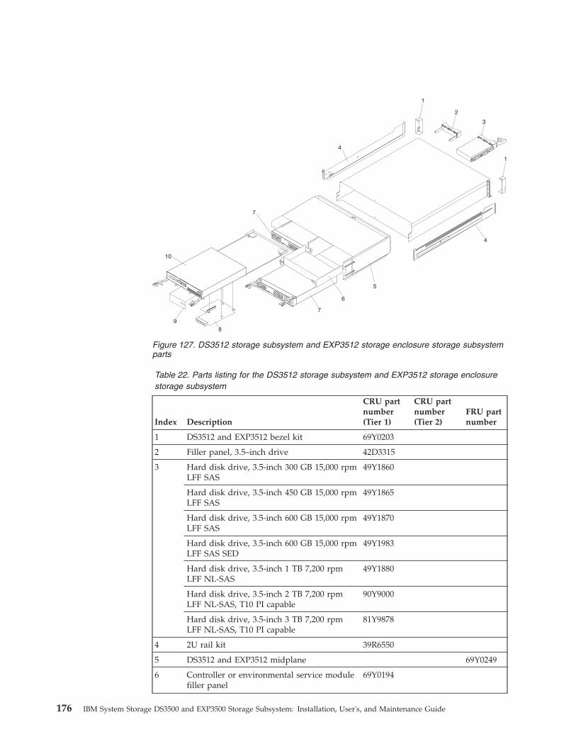
Table 22. Parts listing for the DS3512 storage subsystem and EXP3512 storage enclosurestorage subsystem
Index Description
CRU partnumber(Tier 1)
CRU partnumber(Tier 2)
FRU partnumber
1 DS3512 and EXP3512 bezel kit 69Y0203
2 Filler panel, 3.5–inch drive 42D3315
3 Hard disk drive, 3.5-inch 300 GB 15,000 rpmLFF SAS
49Y1860
Hard disk drive, 3.5-inch 450 GB 15,000 rpmLFF SAS
49Y1865
Hard disk drive, 3.5-inch 600 GB 15,000 rpmLFF SAS
49Y1870
Hard disk drive, 3.5-inch 600 GB 15,000 rpmLFF SAS SED
49Y1983
Hard disk drive, 3.5-inch 1 TB 7,200 rpmLFF NL-SAS
49Y1880
Hard disk drive, 3.5-inch 2 TB 7,200 rpmLFF NL-SAS, T10 PI capable
90Y9000
Hard disk drive, 3.5-inch 3 TB 7,200 rpmLFF NL-SAS, T10 PI capable
81Y9878
4 2U rail kit 39R6550
5 DS3512 and EXP3512 midplane 69Y0249
6 Controller or environmental service modulefiller panel
69Y0194
Figure 127. DS3512 storage subsystem and EXP3512 storage enclosure storage subsystemparts
176 IBM System Storage DS3500 and EXP3500 Storage Subsystem: Installation, User's, and Maintenance Guide
Table 22. Parts listing for the DS3512 storage subsystem and EXP3512 storage enclosurestorage subsystem (continued)
Index Description
CRU partnumber(Tier 1)
CRU partnumber(Tier 2)
FRU partnumber
7 DS3500 Power Supply Unit 00W1521
8 Host interface adapter, 6 Gbps SAS 2-port 69Y2840
Host interface adapter, 8 Gbps FC 4-port 69Y2841
Host interface adapter, 1 Gbps iSCSI 4-port 69Y2842
Host interface adapter, 10 Gbps iSCSI 2-port 81Y9943
9 Filler panel, host port adapter 69Y2897
10 Controller with 1 GB DIMM, no host portexpansion adapter, no backup batterymodule.
00Y5008
DIMM, 2 GB cache memory 69Y2843
Flash memory, cache backup, 8 GB 90Y8691
Backup battery module 69Y2926
IBM 1-meter mini-SAS cable 39R6530
IBM 3-meter mini-SAS cable 39R6532
Service cable 13N1932
Power cord, rack jumper, 2.8-meter 39M5377
Miscellaneous rack mounting hardware kit 39R6551
Environmental service module 69Y0189
8 GB shortwave SFP transceiver 49Y4123
DS3524 storage subsystem and EXP3524 storage enclosure partslisting
Figure 128 on page 178 and the following table provide a parts listing for theDS3524 storage subsystem and EXP3524 storage enclosure.
Chapter 7. Parts listing, DS3500 storage subsystem and EXP3500 storage enclosure 177
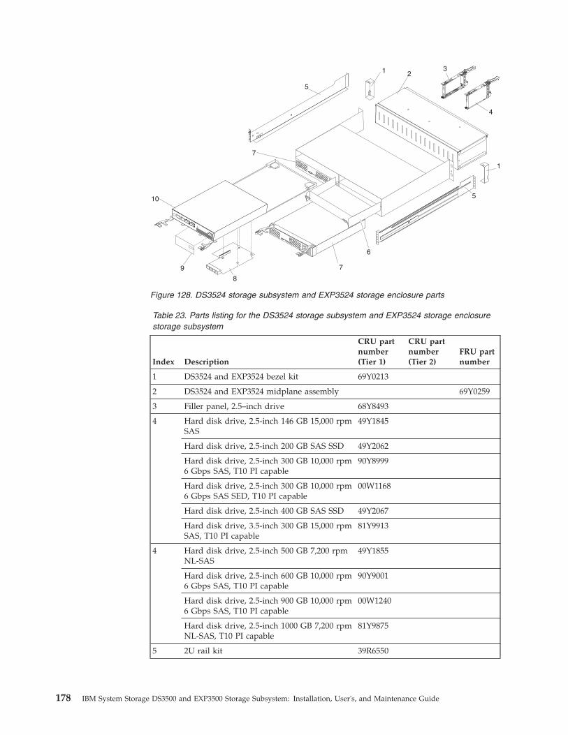
Table 23. Parts listing for the DS3524 storage subsystem and EXP3524 storage enclosurestorage subsystem
Index Description
CRU partnumber(Tier 1)
CRU partnumber(Tier 2)
FRU partnumber
1 DS3524 and EXP3524 bezel kit 69Y0213
2 DS3524 and EXP3524 midplane assembly 69Y0259
3 Filler panel, 2.5–inch drive 68Y8493
4 Hard disk drive, 2.5-inch 146 GB 15,000 rpmSAS
49Y1845
Hard disk drive, 2.5-inch 200 GB SAS SSD 49Y2062
Hard disk drive, 2.5-inch 300 GB 10,000 rpm6 Gbps SAS, T10 PI capable
90Y8999
Hard disk drive, 2.5-inch 300 GB 10,000 rpm6 Gbps SAS SED, T10 PI capable
00W1168
Hard disk drive, 2.5-inch 400 GB SAS SSD 49Y2067
Hard disk drive, 3.5-inch 300 GB 15,000 rpmSAS, T10 PI capable
81Y9913
4 Hard disk drive, 2.5-inch 500 GB 7,200 rpmNL-SAS
49Y1855
Hard disk drive, 2.5-inch 600 GB 10,000 rpm6 Gbps SAS, T10 PI capable
90Y9001
Hard disk drive, 2.5-inch 900 GB 10,000 rpm6 Gbps SAS, T10 PI capable
00W1240
Hard disk drive, 2.5-inch 1000 GB 7,200 rpmNL-SAS, T10 PI capable
81Y9875
5 2U rail kit 39R6550
Figure 128. DS3524 storage subsystem and EXP3524 storage enclosure parts
178 IBM System Storage DS3500 and EXP3500 Storage Subsystem: Installation, User's, and Maintenance Guide
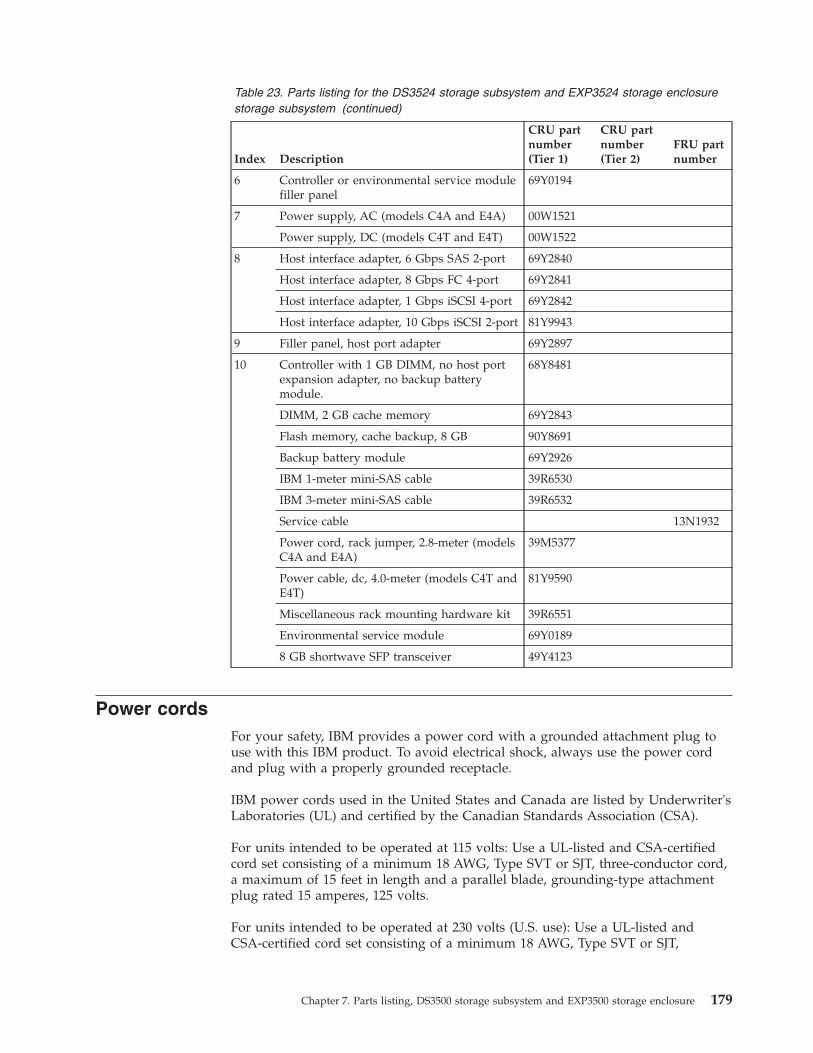
Table 23. Parts listing for the DS3524 storage subsystem and EXP3524 storage enclosurestorage subsystem (continued)
Index Description
CRU partnumber(Tier 1)
CRU partnumber(Tier 2)
FRU partnumber
6 Controller or environmental service modulefiller panel
69Y0194
7 Power supply, AC (models C4A and E4A) 00W1521
Power supply, DC (models C4T and E4T) 00W1522
8 Host interface adapter, 6 Gbps SAS 2-port 69Y2840
Host interface adapter, 8 Gbps FC 4-port 69Y2841
Host interface adapter, 1 Gbps iSCSI 4-port 69Y2842
Host interface adapter, 10 Gbps iSCSI 2-port 81Y9943
9 Filler panel, host port adapter 69Y2897
10 Controller with 1 GB DIMM, no host portexpansion adapter, no backup batterymodule.
68Y8481
DIMM, 2 GB cache memory 69Y2843
Flash memory, cache backup, 8 GB 90Y8691
Backup battery module 69Y2926
IBM 1-meter mini-SAS cable 39R6530
IBM 3-meter mini-SAS cable 39R6532
Service cable 13N1932
Power cord, rack jumper, 2.8-meter (modelsC4A and E4A)
39M5377
Power cable, dc, 4.0-meter (models C4T andE4T)
81Y9590
Miscellaneous rack mounting hardware kit 39R6551
Environmental service module 69Y0189
8 GB shortwave SFP transceiver 49Y4123
Power cordsFor your safety, IBM provides a power cord with a grounded attachment plug touse with this IBM product. To avoid electrical shock, always use the power cordand plug with a properly grounded receptacle.
IBM power cords used in the United States and Canada are listed by Underwriter'sLaboratories (UL) and certified by the Canadian Standards Association (CSA).
For units intended to be operated at 115 volts: Use a UL-listed and CSA-certifiedcord set consisting of a minimum 18 AWG, Type SVT or SJT, three-conductor cord,a maximum of 15 feet in length and a parallel blade, grounding-type attachmentplug rated 15 amperes, 125 volts.
For units intended to be operated at 230 volts (U.S. use): Use a UL-listed andCSA-certified cord set consisting of a minimum 18 AWG, Type SVT or SJT,
Chapter 7. Parts listing, DS3500 storage subsystem and EXP3500 storage enclosure 179
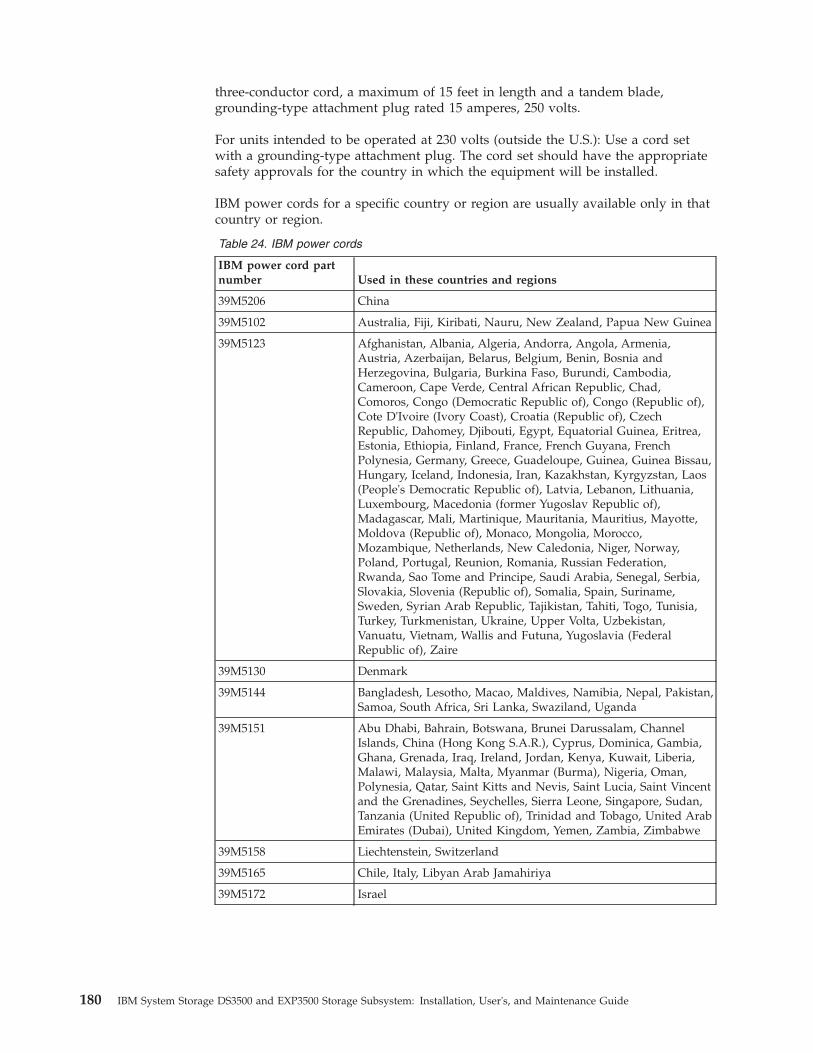
three-conductor cord, a maximum of 15 feet in length and a tandem blade,grounding-type attachment plug rated 15 amperes, 250 volts.
For units intended to be operated at 230 volts (outside the U.S.): Use a cord setwith a grounding-type attachment plug. The cord set should have the appropriatesafety approvals for the country in which the equipment will be installed.
IBM power cords for a specific country or region are usually available only in thatcountry or region.
Table 24. IBM power cords
IBM power cord partnumber Used in these countries and regions
39M5206 China
39M5102 Australia, Fiji, Kiribati, Nauru, New Zealand, Papua New Guinea
39M5123 Afghanistan, Albania, Algeria, Andorra, Angola, Armenia,Austria, Azerbaijan, Belarus, Belgium, Benin, Bosnia andHerzegovina, Bulgaria, Burkina Faso, Burundi, Cambodia,Cameroon, Cape Verde, Central African Republic, Chad,Comoros, Congo (Democratic Republic of), Congo (Republic of),Cote D'Ivoire (Ivory Coast), Croatia (Republic of), CzechRepublic, Dahomey, Djibouti, Egypt, Equatorial Guinea, Eritrea,Estonia, Ethiopia, Finland, France, French Guyana, FrenchPolynesia, Germany, Greece, Guadeloupe, Guinea, Guinea Bissau,Hungary, Iceland, Indonesia, Iran, Kazakhstan, Kyrgyzstan, Laos(People's Democratic Republic of), Latvia, Lebanon, Lithuania,Luxembourg, Macedonia (former Yugoslav Republic of),Madagascar, Mali, Martinique, Mauritania, Mauritius, Mayotte,Moldova (Republic of), Monaco, Mongolia, Morocco,Mozambique, Netherlands, New Caledonia, Niger, Norway,Poland, Portugal, Reunion, Romania, Russian Federation,Rwanda, Sao Tome and Principe, Saudi Arabia, Senegal, Serbia,Slovakia, Slovenia (Republic of), Somalia, Spain, Suriname,Sweden, Syrian Arab Republic, Tajikistan, Tahiti, Togo, Tunisia,Turkey, Turkmenistan, Ukraine, Upper Volta, Uzbekistan,Vanuatu, Vietnam, Wallis and Futuna, Yugoslavia (FederalRepublic of), Zaire
39M5130 Denmark
39M5144 Bangladesh, Lesotho, Macao, Maldives, Namibia, Nepal, Pakistan,Samoa, South Africa, Sri Lanka, Swaziland, Uganda
39M5151 Abu Dhabi, Bahrain, Botswana, Brunei Darussalam, ChannelIslands, China (Hong Kong S.A.R.), Cyprus, Dominica, Gambia,Ghana, Grenada, Iraq, Ireland, Jordan, Kenya, Kuwait, Liberia,Malawi, Malaysia, Malta, Myanmar (Burma), Nigeria, Oman,Polynesia, Qatar, Saint Kitts and Nevis, Saint Lucia, Saint Vincentand the Grenadines, Seychelles, Sierra Leone, Singapore, Sudan,Tanzania (United Republic of), Trinidad and Tobago, United ArabEmirates (Dubai), United Kingdom, Yemen, Zambia, Zimbabwe
39M5158 Liechtenstein, Switzerland
39M5165 Chile, Italy, Libyan Arab Jamahiriya
39M5172 Israel
180 IBM System Storage DS3500 and EXP3500 Storage Subsystem: Installation, User's, and Maintenance Guide
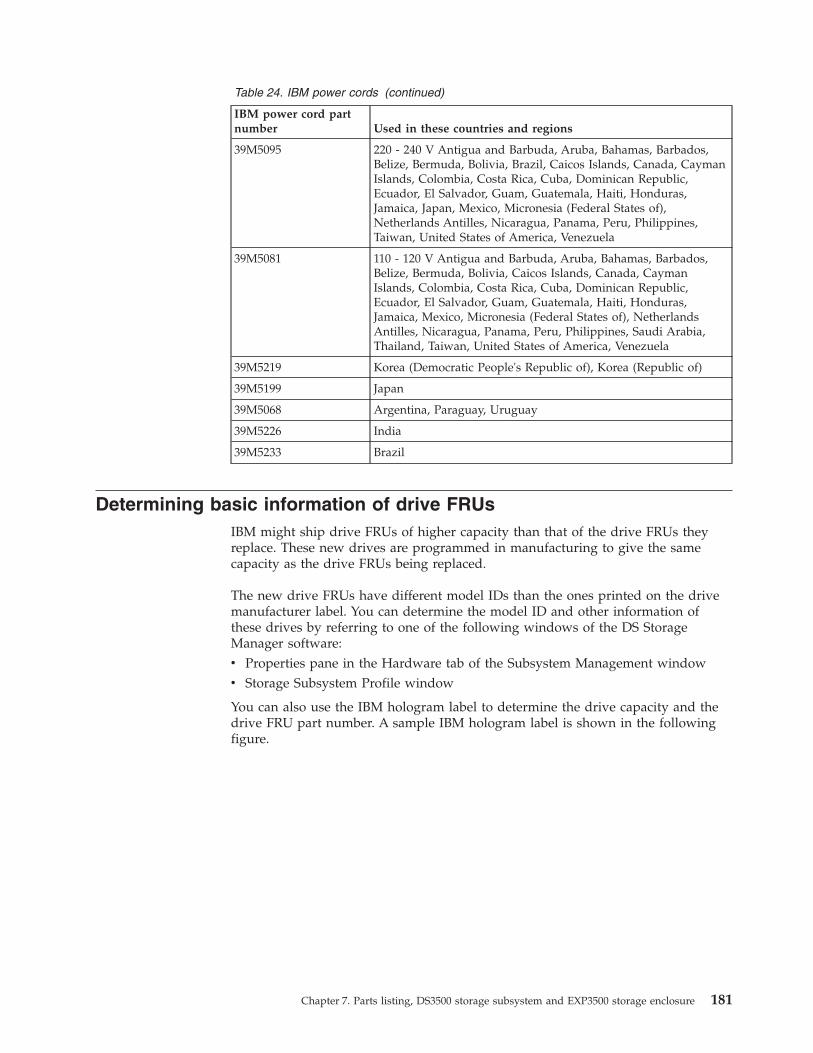
Table 24. IBM power cords (continued)
IBM power cord partnumber Used in these countries and regions
39M5095 220 - 240 V Antigua and Barbuda, Aruba, Bahamas, Barbados,Belize, Bermuda, Bolivia, Brazil, Caicos Islands, Canada, CaymanIslands, Colombia, Costa Rica, Cuba, Dominican Republic,Ecuador, El Salvador, Guam, Guatemala, Haiti, Honduras,Jamaica, Japan, Mexico, Micronesia (Federal States of),Netherlands Antilles, Nicaragua, Panama, Peru, Philippines,Taiwan, United States of America, Venezuela
39M5081 110 - 120 V Antigua and Barbuda, Aruba, Bahamas, Barbados,Belize, Bermuda, Bolivia, Caicos Islands, Canada, CaymanIslands, Colombia, Costa Rica, Cuba, Dominican Republic,Ecuador, El Salvador, Guam, Guatemala, Haiti, Honduras,Jamaica, Mexico, Micronesia (Federal States of), NetherlandsAntilles, Nicaragua, Panama, Peru, Philippines, Saudi Arabia,Thailand, Taiwan, United States of America, Venezuela
39M5219 Korea (Democratic People's Republic of), Korea (Republic of)
39M5199 Japan
39M5068 Argentina, Paraguay, Uruguay
39M5226 India
39M5233 Brazil
Determining basic information of drive FRUsIBM might ship drive FRUs of higher capacity than that of the drive FRUs theyreplace. These new drives are programmed in manufacturing to give the samecapacity as the drive FRUs being replaced.
The new drive FRUs have different model IDs than the ones printed on the drivemanufacturer label. You can determine the model ID and other information ofthese drives by referring to one of the following windows of the DS StorageManager software:v Properties pane in the Hardware tab of the Subsystem Management windowv Storage Subsystem Profile window
You can also use the IBM hologram label to determine the drive capacity and thedrive FRU part number. A sample IBM hologram label is shown in the followingfigure.
Chapter 7. Parts listing, DS3500 storage subsystem and EXP3500 storage enclosure 181
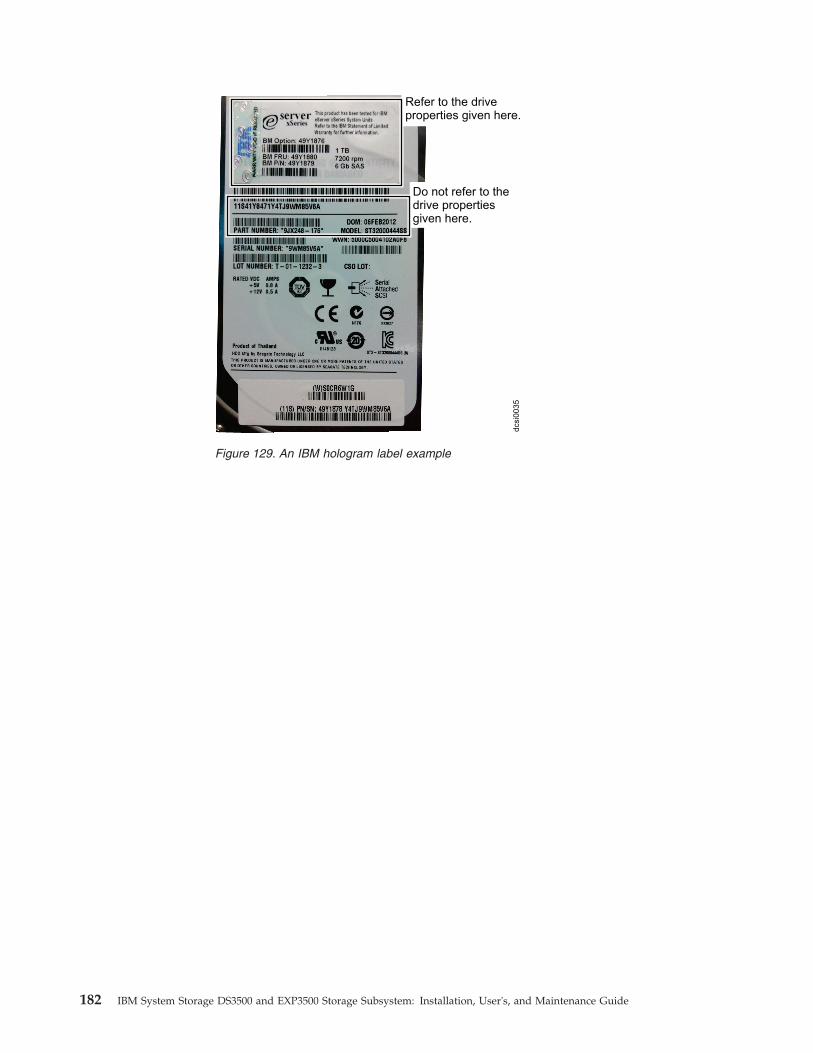
Do not refer to thedrive propertiesgiven here.
Refer to the driveproperties given here.
dcsi0
035
Figure 129. An IBM hologram label example
182 IBM System Storage DS3500 and EXP3500 Storage Subsystem: Installation, User's, and Maintenance Guide

Appendix A. Records
Whenever you add optional devices to the DS3500 storage subsystem or EXP3500storage enclosure, be sure to update the information in this appendix. Accurate,up-to-date records make it easier to add other devices and provide needed datawhenever you contact your IBM technical-support representative.
Identification numbersRecord and retain the following information.
Table 25. Product identification record
Product name IBM System Storage DS3500 or EXP3500
Machine type 1746
Model number
Serial number
The serial number is on the label in the vertical recess on the left bezel. The serialnumber is also on the left chassis flange and on the rear of the chassis. A label thatincludes the machine type, model, and serial number is on the top front rightchassis corner.
Hard disk drive locationsUse Table 26 on page 184 to keep a record of the drives that are installed in orattached to the DS3500 or EXP3500. This information can be helpful when youinstall additional drives or if you have to report a hardware problem. Make a copyof this table before you record information in it, in case you need extra space towrite new values later, or when you update the configuration.
Serial number label
Product name Machine type, model, andserial number label
Figure 130. Serial number location on the DS3500
© Copyright IBM Corp. 2010, 2013 183

Table 26. Drive location information record
Drive location Drive part and model number Drive serial number
Bay 1
Bay 2
Bay 3
Bay 4
Bay 5
Bay 6
Bay 7
Bay 8
Bay 9
Bay 10
Bay 11
Bay 12
Bay 13
Bay 14
Bay 15
Bay 16
Bay 17
Bay 18
Bay 19
Bay 20
Bay 21
Bay 22
Bay 23
Bay 24
Storage subsystem and controller information recordTable 27 provides a data sheet for recording storage subsystem names,management types, Ethernet hardware addresses, and IP addresses. Make a copyof this table and complete the information for your storage subsystems andcontrollers. Use the information to set up the BOOTP table for the network serverand the host or Domain Name System (DNS) table. The information is also helpfulif you add storage subsystems after initial installation. See the Storage Managerdocumentation for detailed instructions for obtaining the information. For a sampleinformation record, see Table 28 on page 185.
Table 27. Storage subsystem and controller information record
Storagesubsystem name
Managementmethod
Controller Ethernet and IPaddresses, and host name
Host IP addressand host name
Controller A Controller B
184 IBM System Storage DS3500 and EXP3500 Storage Subsystem: Installation, User's, and Maintenance Guide

Table 27. Storage subsystem and controller information record (continued)
Storagesubsystem name
Managementmethod
Controller Ethernet and IPaddresses, and host name
Host IP addressand host name
Controller A Controller B
Table 28 shows a sample information record. This network contains storagesubsystems that are managed by using both the direct-management andhost-agent-management method.
Table 28. Sample information record
Storagesubsystem name
Managementmethod
Controller Ethernet and IPaddresses, and host name
Host IP addressand host name
Controller A Controller B
Finance Direct HardwareEthernet address= 00a0b8020420
HardwareEthernet address= 00a0b80000d8
IP address =192.168.128.101
IP address =192.168.128.102
Host = Denver_a Host = Denver_b
Engineering Host-agent IP address =192.168.2.22
Host = Atlanta
Appendix A. Records 185

186 IBM System Storage DS3500 and EXP3500 Storage Subsystem: Installation, User's, and Maintenance Guide
Appendix B. Getting help and technical assistance
If you need help, service, or technical assistance or just want more informationabout IBM products, you will find a wide variety of sources available from IBM toassist you.
Use this information to obtain additional information about IBM and IBMproducts, determine what to do if you experience a problem with your IBM systemor optional device, and determine whom to call for service, if it is necessary.
Before you callBefore you call, ensure that you have taken these steps to try to solve the problemyourself.
If you believe that you require IBM to perform warranty service on your IBMproduct, the IBM service technicians will be able to assist you more efficiently ifyou prepare before you call.v Check for updated firmware and operating-system device drivers for your IBM
product. The IBM Warranty terms and conditions state that you, the owner ofthe IBM product, are responsible for maintaining and updating all software andfirmware for the product (unless it is covered by an additional maintenancecontract). Your IBM service technician will request that you upgrade yoursoftware and firmware if the problem has a documented solution within asoftware upgrade.You can obtain the latest downloads for your IBM product fromhttp://www.ibm.com/support/fixcentral/systemx/groupView?query.productGroup=ibm%2FSystemx ..
v If you have installed new hardware or software in your environment, checkhttp://www.ibm.com/systems/info/x86servers/serverproven/compat/us/ toensure that the hardware and software is supported by your IBM product.
v Use the troubleshooting information in your system documentation, and use thediagnostic tools that come with your IBM product. Information about diagnostictools is in the Problem Determination and Service Guide on the IBM DocumentationCD that comes with your product.
v Go to http://www.ibm.com/systems/support/ to check for information to helpyou solve the problem.
v Gather the following information to provide to IBM service. This data will helpIBM service quickly provide a solution to your problem and ensure that youreceive the level of service for which you might have contracted.– Hardware and Software Maintenance agreement contract numbers, if
applicable– Machine type number (IBM 4-digit machine identifier)– Model number– Serial number– Current system UEFI (or BIOS) and firmware levels– Other pertinent information such as error messages and logs
v Go to http://www.ibm.com/support/electronic/ to submit an Electronic ServiceRequest. Submitting an Electronic Service Request will start the process of
© Copyright IBM Corp. 2010, 2013 187
determining a solution to your problem by making the pertinent informationavailable to IBM service quickly and efficiently. IBM service technicians can startworking on your solution as soon as you have completed and submitted anElectronic Service Request.
Using the documentationInformation about your IBM system and preinstalled software, if any, or optionaldevice is available in the documentation that comes with the product. Thatdocumentation can include printed documents, online documents, readme files,and help files.
See the troubleshooting information in your system documentation for instructionsfor using the diagnostic programs. The troubleshooting information or thediagnostic programs might tell you that you need additional or updated devicedrivers or other software. IBM maintains pages on the World Wide Web where youcan get the latest technical information and download device drivers and updates.To access these pages, go to http://www.ibm.com/systems/support/ .
You can find the most up-to-date information for System x® products athttp://www.ibm.com/systems/x/ .
Getting help and information from the World Wide WebOn the World Wide Web, up-to-date information about IBM systems, optionaldevices, services, and support is available at http://www.ibm.com/systems/support/ .
You can find the most up-to-date product information for System x products athttp://www.ibm.com/systems/x/ .
Software service and supportThrough IBM Support Line, you can get telephone assistance, for a fee, with usage,configuration, and software problems with your IBM products.
For more information about Support Line and other IBM services, seehttp://www.ibm.com/services/us/index.wss or see http://www.ibm.com/planetwide/ for support telephone numbers. In the U.S. and Canada, call1-800-IBM-SERV (1-800-426-7378).
Hardware service and supportYou can receive hardware service through your IBM reseller or IBM Services.
To locate a reseller authorized by IBM to provide warranty service, go tohttp://www.ibm.com/partnerworld/ and click Find Business Partners on theright side of the page. For IBM support telephone numbers, seehttp://www.ibm.com/planetwide/ . In the U.S. and Canada, call 1-800-IBM-SERV(1-800-426-7378).
In the U.S. and Canada, hardware service and support is available 24 hours a day,7 days a week. In the U.K., these services are available Monday through Friday,from 9 a.m. to 6 p.m.
188 IBM System Storage DS3500 and EXP3500 Storage Subsystem: Installation, User's, and Maintenance Guide
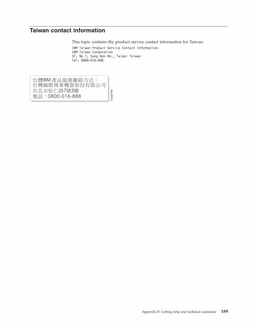
Taiwan contact information
This topic contains the product service contact information for Taiwan.IBM Taiwan Product Service Contact Information:IBM Taiwan Corporation3F, No 7, Song Ren Rd., Taipei TaiwanTel: 0800-016-888
f2c0
07
90
Appendix B. Getting help and technical assistance 189

190 IBM System Storage DS3500 and EXP3500 Storage Subsystem: Installation, User's, and Maintenance Guide

Notices
This information was developed for products and services offered in the U.S.A.
IBM may not offer the products, services, or features discussed in this document inother countries. Consult your local IBM representative for information on theproducts and services currently available in your area. Any reference to an IBMproduct, program, or service is not intended to state or imply that only that IBMproduct, program, or service may be used. Any functionally equivalent product,program, or service that does not infringe any IBM intellectual property right maybe used instead. However, it is the user's responsibility to evaluate and verify theoperation of any non-IBM product, program, or service.
IBM may have patents or pending patent applications covering subject matterdescribed in this document. The furnishing of this document does not grant youany license to these patents. You can send license inquiries, in writing, to:
IBM Director of LicensingIBM CorporationNorth Castle DriveArmonk, NY 10504-1785U.S.A.
The following paragraph does not apply to the United Kingdom or any othercountry where such provisions are inconsistent with local law:INTERNATIONAL BUSINESS MACHINES CORPORATION PROVIDES THISPUBLICATION "AS IS" WITHOUT WARRANTY OF ANY KIND, EITHEREXPRESS OR IMPLIED, INCLUDING, BUT NOT LIMITED TO, THE IMPLIEDWARRANTIES OF NON-INFRINGEMENT, MERCHANTABILITY OR FITNESSFOR A PARTICULAR PURPOSE. Some states do not allow disclaimer of express orimplied warranties in certain transactions, therefore, this statement may not applyto you.
This information could include technical inaccuracies or typographical errors.Changes are periodically made to the information herein; these changes will beincorporated in new editions of the publication. IBM may make improvementsand/or changes in the product(s) and/or the program(s) described in thispublication at any time without notice.
Any references in this information to non-IBM Web sites are provided forconvenience only and do not in any manner serve as an endorsement of those Websites. The materials at those Web sites are not part of the materials for this IBMproduct and use of those Web sites is at your own risk.
IBM may use or distribute any of the information you supply in any way itbelieves appropriate without incurring any obligation to you.
Any performance data contained herein was determined in a controlledenvironment. Therefore, the results obtained in other operating environments mayvary significantly. Some measurements may have been made on development-levelsystems and there is no guarantee that these measurements will be the same ongenerally available systems. Furthermore, some measurements may have been
© Copyright IBM Corp. 2010, 2013 191
estimated through extrapolation. Actual results may vary. Users of this documentshould verify the applicable data for their specific environment.
Information concerning non-IBM products was obtained from the suppliers ofthose products, their published announcements or other publicly available sources.IBM has not tested those products and cannot confirm the accuracy ofperformance, compatibility or any other claims related to non-IBM products.Questions on the capabilities of non-IBM products should be addressed to thesuppliers of those products.
All statements regarding IBM's future direction or intent are subject to change orwithdrawal without notice, and represent goals and objectives only.
All IBM prices shown are IBM's suggested retail prices, are current and are subjectto change without notice. Dealer prices may vary.
This information is for planning purposes only. The information herein is subject tochange before the products described become available.
This information contains examples of data and reports used in daily businessoperations. To illustrate them as completely as possible, the examples include thenames of individuals, companies, brands, and products. All of these names arefictitious and any similarity to the names and addresses used by an actual businessenterprise is entirely coincidental.
If you are viewing this information softcopy, the photographs and colorillustrations may not appear.
TrademarksIBM, the IBM logo, and ibm.com® are trademarks or registered trademarks ofInternational Business Machines Corp., registered in many jurisdictions worldwide.Other product and service names might be trademarks of IBM or other companies.A current list of IBM trademarks is available on the web at Copyright andtrademark information at www.ibm.com/legal/copytrade.shtml.
Adobe, the Adobe logo, PostScript, and the PostScript logo are either registeredtrademarks or trademarks of Adobe Systems Incorporated in the United States,and/or other countries.
Intel, Intel logo, Intel Inside, Intel Inside logo, Intel Centrino, Intel Centrino logo,Celeron, Intel Xeon, Intel SpeedStep, Itanium, and Pentium are trademarks orregistered trademarks of Intel Corporation or its subsidiaries in the United Statesand other countries.
Linux is a registered trademark of Linus Torvalds in the United States, othercountries, or both.
Microsoft, Windows, Windows NT, and the Windows logo are trademarks ofMicrosoft Corporation in the United States, other countries, or both.
UNIX is a registered trademark of The Open Group in the United States and othercountries.
Java and all Java-based trademarks and logos are trademarks or registeredtrademarks of Oracle and/or its affiliates.
192 IBM System Storage DS3500 and EXP3500 Storage Subsystem: Installation, User's, and Maintenance Guide

Important notesProcessor speed indicates the internal clock speed of the microprocessor; otherfactors also affect application performance.
This product is not intended to be connected directly or indirectly by any meanswhatsoever to interfaces of public telecommunications networks, nor is it intendedto be used in a public services network.
CD or DVD drive speed is the variable read rate. Actual speeds vary and are oftenless than the possible maximum.
When referring to processor storage, real and virtual storage, or channel volume,KB stands for 1024 bytes, MB stands for 1,048,576 bytes, and GB stands for1,073,741,824 bytes.
When referring to hard disk drive capacity or communications volume, MB standsfor 1,000,000 bytes, and GB stands for 1,000,000,000 bytes. Total user-accessiblecapacity can vary depending on operating environments.
Maximum internal hard disk drive capacities assume the replacement of anystandard hard disk drives and population of all hard disk drive bays with thelargest currently supported drives that are available from IBM.
Maximum memory might require replacement of the standard memory with anoptional memory module.
IBM makes no representation or warranties regarding non-IBM products andservices that are ServerProven®, including but not limited to the implied warrantiesof merchantability and fitness for a particular purpose. These products are offeredand warranted solely by third parties.
IBM makes no representations or warranties with respect to non-IBM products.Support (if any) for the non-IBM products is provided by the third party, not IBM.
Some software might differ from its retail version (if available) and might notinclude user manuals or all program functionality.
Particulate contaminationAttention: Airborne particulates (including metal flakes or particles) and reactivegases acting alone or in combination with other environmental factors such ashumidity or temperature might pose a risk to the device that is described in thisdocument.
Risks that are posed by the presence of excessive particulate levels orconcentrations of harmful gases include damage that might cause the device tomalfunction or cease functioning altogether. This specification sets forth limits forparticulates and gases that are intended to avoid such damage. The limits must notbe viewed or used as definitive limits, because numerous other factors, such astemperature or moisture content of the air, can influence the impact of particulatesor environmental corrosives and gaseous contaminant transfer. In the absence ofspecific limits that are set forth in this document, you must implement practicesthat maintain particulate and gas levels that are consistent with the protection ofhuman health and safety. If IBM determines that the levels of particulates or gasesin your environment have caused damage to the device, IBM may condition
Notices 193
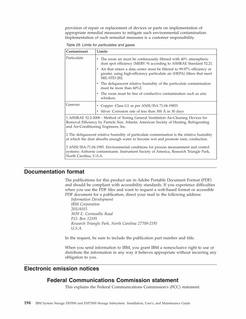
provision of repair or replacement of devices or parts on implementation ofappropriate remedial measures to mitigate such environmental contamination.Implementation of such remedial measures is a customer responsibility.
Table 29. Limits for particulates and gases
Contaminant Limits
Particulate v The room air must be continuously filtered with 40% atmosphericdust spot efficiency (MERV 9) according to ASHRAE Standard 52.21.
v Air that enters a data center must be filtered to 99.97% efficiency orgreater, using high-efficiency particulate air (HEPA) filters that meetMIL-STD-282.
v The deliquescent relative humidity of the particulate contaminationmust be more than 60%2.
v The room must be free of conductive contamination such as zincwhiskers.
Gaseous v Copper: Class G1 as per ANSI/ISA 71.04-19853
v Silver: Corrosion rate of less than 300 Å in 30 days
1 ASHRAE 52.2-2008 - Method of Testing General Ventilation Air-Cleaning Devices forRemoval Efficiency by Particle Size. Atlanta: American Society of Heating, Refrigeratingand Air-Conditioning Engineers, Inc.
2 The deliquescent relative humidity of particulate contamination is the relative humidityat which the dust absorbs enough water to become wet and promote ionic conduction.
3 ANSI/ISA-71.04-1985. Environmental conditions for process measurement and controlsystems: Airborne contaminants. Instrument Society of America, Research Triangle Park,North Carolina, U.S.A.
Documentation formatThe publications for this product are in Adobe Portable Document Format (PDF)and should be compliant with accessibility standards. If you experience difficultieswhen you use the PDF files and want to request a web-based format or accessiblePDF document for a publication, direct your mail to the following address:
Information DevelopmentIBM Corporation205/A0153039 E. Cornwallis RoadP.O. Box 12195Research Triangle Park, North Carolina 27709-2195U.S.A.
In the request, be sure to include the publication part number and title.
When you send information to IBM, you grant IBM a nonexclusive right to use ordistribute the information in any way it believes appropriate without incurring anyobligation to you.
Electronic emission notices
Federal Communications Commission statementThis explains the Federal Communications Commission's (FCC) statement.
194 IBM System Storage DS3500 and EXP3500 Storage Subsystem: Installation, User's, and Maintenance Guide

This equipment has been tested and found to comply with the limits for a Class Adigital device, pursuant to Part 15 of the FCC Rules. These limits are designed toprovide reasonable protection against harmful interference when the equipment isoperated in a commercial environment. This equipment generates, uses, and canradiate radio frequency energy and, if not installed and used in accordance withthe instruction manual, might cause harmful interference to radio communications.Operation of this equipment in a residential area is likely to cause harmfulinterference, in which case the user will be required to correct the interference athis own expense.
Properly shielded and grounded cables and connectors must be used in order tomeet FCC emission limits. IBM is not responsible for any radio or televisioninterference caused by using other than recommended cables and connectors, or byunauthorized changes or modifications to this equipment. Unauthorized changesor modifications could void the user's authority to operate the equipment.
This device complies with Part 15 of the FCC Rules. Operation is subject to thefollowing two conditions: (1) this device might not cause harmful interference, and(2) this device must accept any interference received, including interference thatmight cause undesired operation.
Industry Canada compliance statementThis Class A digital apparatus complies with Canadian ICES-003.
Cet appareil numérique de la classe A est conform à la norme NMB-003 duCanada.
Australia and New Zealand Class A StatementAttention: This is a Class A product. In a domestic environment this productmight cause radio interference in which case the user might be required to takeadequate measures.
European Union Electromagnetic Compatibility DirectiveThis product is in conformity with the protection requirements of European Union(EU) Council Directive 2004/108/EC on the approximation of the laws of theMember States relating to electromagnetic compatibility. IBM cannot acceptresponsibility for any failure to satisfy the protection requirements resulting from anon-recommended modification of the product, including the fitting of non-IBMoption cards.
Attention: This is an EN 55022 Class A product. In a domestic environment thisproduct might cause radio interference in which case the user might be required totake adequate measures.
Responsible Manufacturer:
International Business Machines Corp.New Orchard RoadArmonk, New York 10504914-499-1900
European community contact:
Notices 195

IBM Deutschland GmbHTechnical Regulations, Department M372IBM-Allee 1, 71139 Ehningen, GermanyTele: +49 7032 15 2941
e-mail: [email protected]
Germany Electromagnetic compatibility directiveDeutschsprachiger EU Hinweis: Hinweis für Geräte der Klasse A EU-Richtliniezur Elektromagnetischen Verträglichkeit
Dieses Produkt entspricht den Schutzanforderungen der EU-Richtlinie2004/108/EG zur Angleichung der Rechtsvorschriften über die elektromagnetischeVerträglichkeit in den EU-Mitgliedsstaaten und hält die Grenzwerte der EN 55022Klasse A ein.
Um dieses sicherzustellen, sind die Geräte wie in den Handbüchern beschrieben zuinstallieren und zu betreiben. Des Weiteren dürfen auch nur von der IBMempfohlene Kabel angeschlossen werden. IBM übernimmt keine Verantwortung fürdie Einhaltung der Schutzanforderungen, wenn das Produkt ohne Zustimmung derIBM verändert bzw. wenn Erweiterungskomponenten von Fremdherstellern ohneEmpfehlung der IBM gesteckt/eingebaut werden.
EN 55022 Klasse A Geräte müssen mit folgendem Warnhinweis versehen werden:
"Warnung: Dieses ist eine Einrichtung der Klasse A. Diese Einrichtung kann imWohnbereich Funk-Störungen verursachen; in diesem Fall kann vom Betreiberverlangt werden, angemessene Mabnahmen zu ergreifen und dafüraufzukommen."
Deutschland: Einhaltung des Gesetzes über die elektromagnetischeVerträglichkeit von Geräten
Dieses Produkt entspricht dem "Gesetz über die elektromagnetische Verträglichkeitvon Geräten (EMVG)." Dies ist die Umsetzung der EU-Richtlinie 2004/108/EG inder Bundesrepublik Deutschland.
Zulassungsbescheinigung laut dem Deutschen Gesetz über dieelektromagnetische Verträglichkeit von Geräten (EMVG) (bzw. der EMC EGRichtlinie 2004/108/EG) für Geräte der Klasse A
Dieses Gerät ist berechtigt, in übereinstimmung mit dem Deutschen EMVG dasEG-Konformitätszeichen - CE - zu führen.
Verantwortlich für die Einhaltung der EMV Vorschriften ist der Hersteller:International Business Machines Corp.New Orchard RoadArmonk,New York 10504Tel: 914-499-1900
Der verantwortliche Ansprechpartner des Herstellers in der EU ist:
IBM Deutschland GmbHTechnical Regulations, Abteilung M372IBM-Allee 1, 71139 Ehningen, GermanyTele: +49 7032 15 2941e-mail: [email protected]
196 IBM System Storage DS3500 and EXP3500 Storage Subsystem: Installation, User's, and Maintenance Guide

Generelle Informationen:
Das Gerät erfüllt die Schutzanforderungen nach EN 55024 und EN 55022 KlasseA.
Japan Voluntary Control Council for Interference (VCCI) ClassA Statement
Japan Electronics and Information Technology IndustriesAssociation (JEITA) Statement (less than or equal to 20 A perphase)
Korean Communications Commission (KCC) Class AStatement
Russia Electromagnetic Interference (EMI) Class A Statement
jjieta
1
rusem
i
Notices 197

People's Republic of China Class A Electronic Emissionstatement
Taiwan Class A compliance statement
198 IBM System Storage DS3500 and EXP3500 Storage Subsystem: Installation, User's, and Maintenance Guide

Index
Aac power connector 13ac power LED 88ac power recovery 22ac power supply
cabling 77connector 13described 13LEDs 88switch 13
ac power supply specifications 4ac power switch 13accessible documentation 194airflow 13, 14, 22area requirements 17assistance, getting 187attention notices 4
Bbattery
LEDs 102overview 15replacing 102, 148
bays, drive 10, 89, 121best practices 8bezels
drive labels 11LEDs 10, 89replacing 156
BladeCenter configuration, installing 75
Ccabling 45cabling the ac power supply 77cabling the dc power supply 78cabling the DS3500
connecting host to controller 76cabling the storage subsystem
connecting host to controller 59, 64,70
connecting power 48connecting secondary interface
cables 55connecting storage enclosures 48topologies 50
cache batterySee battery 102
cache memorycache active LED 101size of 101
caution statements 4chaining the EXP3500 storage
enclosures 45, 46, 47checking the LEDs 88codes
category 169detail 169
componentsbattery 15controllers 9drives 9, 121host port adapter 12power supplies 9weights 18
configuration, installing aBladeCenter 75
configuration, installing the storagesubsystem 58
contamination, particulate andgaseous 193
controllercache battery 102cache memory 101connecting Ethernet cable to 55connecting host to 59, 64, 70, 76description 12DIMM 101host port adapter 12information record 184LEDs 90location 12replacing 109sample information record 184
controllers, dualhost port adapter 12must be identical 12requirements 12
Controllers, working with 105cooling 22customer replaceable units (CRUs) 9,
175removing a drive 122replacing the battery 148replacing the controllers 109
Ddanger statements 4data sheet 184data sheet, sample 184dc in LED 88dc power connector 14dc power LED 88dc power recovery 22dc power supply
cabling 78connector 14described 14replacing 137switch 14
DC power supplyLEDs 88
dc power switch 14devices, installing and replacing 105diagnostic code 169dimensions 4direct management method 57
documentationusing 188
documentation format 194documentation inventory 26drive
removal 122replacing all at same time 126, 128replacing one at a time 126, 130
drive labels 121drive LEDs
activity LED 121status LED 121
drive path, redundant 45, 46, 47drive, hard disk
no hot-swapping when LEDs lit 12replacing all at same time 126, 128replacing one at a time 126, 130working with 121
DS3500cache memory and cache battery 101configuring 56dimensions 17health check process 81installing the configuration 58
DS3500 storage subsystemSolving problems 161
DS3500 storage subsystem overview 2DS3512 storage subsystem parts
listing 175DS3524 storage subsystem parts
listing 177
Eelectrical input specifications 4electrical requirements 21Electronic emission notices 194emergency shutdown 98enclosure ID 33
automatic 33setting 33
Environmental service modules, workingwith 157
environmental specifications 4ESM
connectors 45LEDs 94replacing 158
Ethernetcabling 26connection to management station 55connectors 12, 56
EXP3500chaining 46
EXP3500 storage enclosurechaining 45, 47Overview 3
EXP3500 storage enclosure, overview 3EXP3512 storage enclosure parts
listing 175
© Copyright IBM Corp. 2010, 2013 199
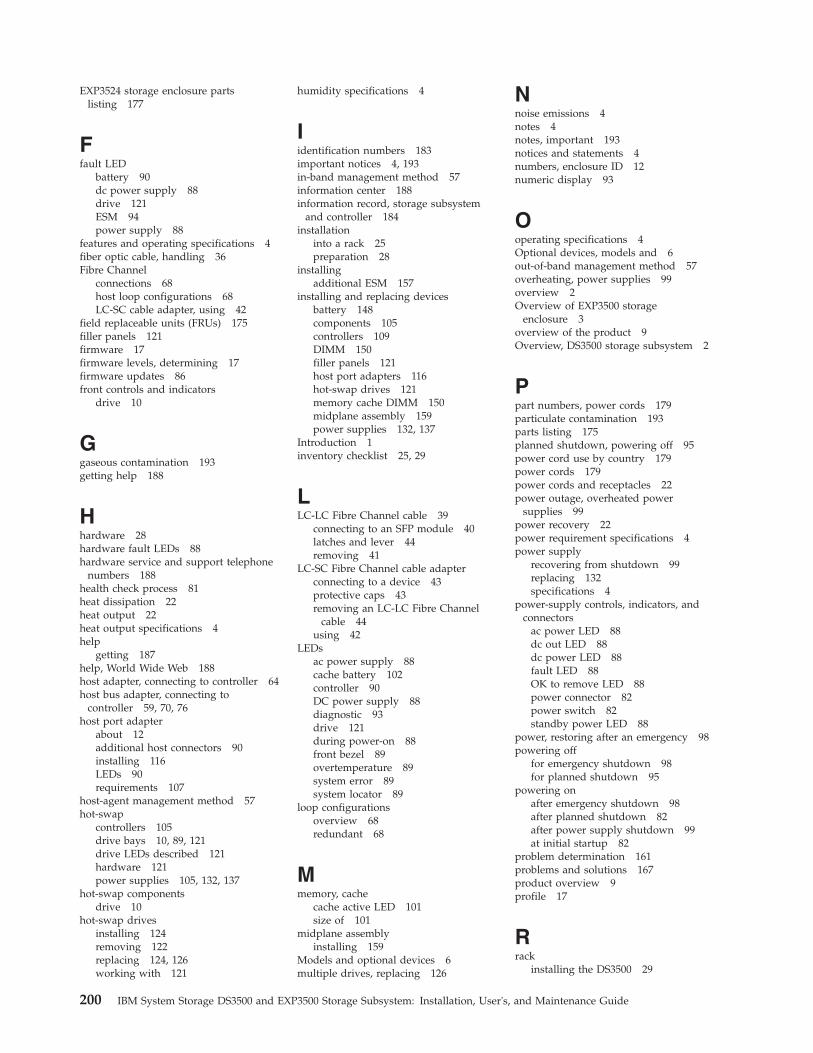
EXP3524 storage enclosure partslisting 177
Ffault LED
battery 90dc power supply 88drive 121ESM 94power supply 88
features and operating specifications 4fiber optic cable, handling 36Fibre Channel
connections 68host loop configurations 68LC-SC cable adapter, using 42
field replaceable units (FRUs) 175filler panels 121firmware 17firmware levels, determining 17firmware updates 86front controls and indicators
drive 10
Ggaseous contamination 193getting help 188
Hhardware 28hardware fault LEDs 88hardware service and support telephone
numbers 188health check process 81heat dissipation 22heat output 22heat output specifications 4help
getting 187help, World Wide Web 188host adapter, connecting to controller 64host bus adapter, connecting to
controller 59, 70, 76host port adapter
about 12additional host connectors 90installing 116LEDs 90requirements 107
host-agent management method 57hot-swap
controllers 105drive bays 10, 89, 121drive LEDs described 121hardware 121power supplies 105, 132, 137
hot-swap componentsdrive 10
hot-swap drivesinstalling 124removing 122replacing 124, 126working with 121
humidity specifications 4
Iidentification numbers 183important notices 4, 193in-band management method 57information center 188information record, storage subsystem
and controller 184installation
into a rack 25preparation 28
installingadditional ESM 157
installing and replacing devicesbattery 148components 105controllers 109DIMM 150filler panels 121host port adapters 116hot-swap drives 121memory cache DIMM 150midplane assembly 159power supplies 132, 137
Introduction 1inventory checklist 25, 29
LLC-LC Fibre Channel cable 39
connecting to an SFP module 40latches and lever 44removing 41
LC-SC Fibre Channel cable adapterconnecting to a device 43protective caps 43removing an LC-LC Fibre Channel
cable 44using 42
LEDsac power supply 88cache battery 102controller 90DC power supply 88diagnostic 93drive 121during power-on 88front bezel 89overtemperature 89system error 89system locator 89
loop configurationsoverview 68redundant 68
Mmemory, cache
cache active LED 101size of 101
midplane assemblyinstalling 159
Models and optional devices 6multiple drives, replacing 126
Nnoise emissions 4notes 4notes, important 193notices and statements 4numbers, enclosure ID 12numeric display 93
Ooperating specifications 4Optional devices, models and 6out-of-band management method 57overheating, power supplies 99overview 2Overview of EXP3500 storage
enclosure 3overview of the product 9Overview, DS3500 storage subsystem 2
Ppart numbers, power cords 179particulate contamination 193parts listing 175planned shutdown, powering off 95power cord use by country 179power cords 179power cords and receptacles 22power outage, overheated power
supplies 99power recovery 22power requirement specifications 4power supply
recovering from shutdown 99replacing 132specifications 4
power-supply controls, indicators, andconnectors
ac power LED 88dc out LED 88dc power LED 88fault LED 88OK to remove LED 88power connector 82power switch 82standby power LED 88
power, restoring after an emergency 98powering off
for emergency shutdown 98for planned shutdown 95
powering onafter emergency shutdown 98after planned shutdown 82after power supply shutdown 99at initial startup 82
problem determination 161problems and solutions 167product overview 9profile 17
Rrack
installing the DS3500 29
200 IBM System Storage DS3500 and EXP3500 Storage Subsystem: Installation, User's, and Maintenance Guide

rack (continued)site preparation 28
recordsdrive locations 183identification numbers 183
redundant drive channel pair 49redundant drive path 45, 46, 47redundant host loops 68replacement parts 175replacing
ESM 158replacing components
battery 148bezels 156controller 109dc power supply 137hot-swap drives 124power supply 132Service Action Allowed Status
LED 105required tools 28restoring power
after an emergency 98after planned shutdown 82after power supply shutdown 99after unplanned shutdown 98
Ssafety ixsafety statements ix, xsafety, static-sensitive devices 27sample information record, storage
subsystem and controller 184sequence codes 169service and support
before you call 187hardware 188software 188
seven-segment numeric display 169shutdown, emergency 98site preparation 29size 4small-form-factor pluggable (SFP) module
connecting an LC-LC Fibre Channelcable 40
important information about 36protective cap 38removal 38removing an LC-LC cable 41static-protective package 37
software and firmware upgrades 15software service and support telephone
numbers 188Solving problems
DS3500 storage subsystem 161specifications 17specifications, DS3500 4standby power LED 88startup sequence 82statements and notices 4static-sensitive devices, handling 27storage enclosure
connecting to storage subsystem 48turning on before storage
subsystem 128
Storage Managerinstalling 85using to monitor storage subsystem
status 85storage manager software and hardware
compatibility 15storage subsystem
ac power supply 13airflow 13, 14checking status 88dc power supply 14enclosure ID 12fans 13, 14fault LEDs 88identification numbers 183information record 184performing an emergency
shutdown 98records 183restoring power after an
emergency 98sample information record 184startup sequence 82troubleshooting 87turning off 95turning on 82
storage subsystem configuration,installing 58
storage subsystem profile 9Storage Subsystem Profile 17
TT10 PI 15T10PI 15temperature and humidity 19temperature specifications 4temperature, maximum 99tools 28trademarks 192troubleshooting 161, 167
no power 99overheating problem 99procedure 87
TroubleshootingDS3500 storage subsystem 161
turning off powerfor emergency shutdown 98for planned shutdown 95
turning on powerafter emergency shutdown 98after power supply shutdown 99at initial startup 82
Uupgrades, support code 15user controls 12
Wweight 4wiring and power 21Working with controllers 105Working with environmental service
modules 157
Index 201

202 IBM System Storage DS3500 and EXP3500 Storage Subsystem: Installation, User's, and Maintenance Guide

����
Part Number: 46W6890
Printed in USA
GA32-0952-06
(1P)
P/N:
46W6
890