installation, start-up and service instructions · installation, start-up and service instructions...
TRANSCRIPT

50HJ008-014Single-Package Rooftop
Electric Cooling Units
Installation, Start-Up andService Instructions
CONTENTS
PageSAFETY CONSIDERATIONS ...................... 1INSTALLATION ................................ 1-46Step 1 -- Provide Unit Support ................... 1• ROOF CURB• SLAB MOUNT• ALTERNATE UNIT SUPPORTStep 2 -- Field Fabricate Ductwork ............... 2Step 3 -- Install Condensate Drain Line
and External Trap .............................. 2Step 4 -- Rig and Place Unit ..................... 4• POSITIONINGStep 5 -- Make Electrical Connections ........... 7• FIELD POWER SUPPLY• FIELD CONTROL WIRING• HEAT ANTICIPATOR SETTINGSStep 6 -- Adjust Factory-Installed
Options ....................................... 12• HUMIDI-MIZER TM ADAPTIVE DEHUMIDIFICA-
TION SYSTEM• DISCONNECT SWITCH• CONVENIENCE OUTLET• NOVAR CONTROLS• MANUAL OUTDOOR-AIR DAMPER• PREMIERLINK r_'_CONTROL• OPTIONAL ECONOMI$ER IV AND ECONOMI$ER2• ECONOMI$ER IV STANDARD SENSORS• ECONOMI$ER IV CONTROL MODESStep 7 -- Adjust Evaporator-Fan Speed ......... 25PRE-START-UP .................................. 43
START-UP .................................... 43-47SERVICE ..................................... 47-51TROUBLESHOOTING ......................... 52-55INDEX ........................................... 56START-UP CHECKLIST ........................ CL-I
SAFETY CONSIDERATIONS
Installation and sel-,Ticingof air-conditioning equipment canbe hazardous due to system pressure and electric_d compo-nents. Only trained and qualified service personnel shouldinstall, repair, or service ai>conditioning equipment.
Untrained personnel can perform basic maintenance func-tions of cleaning coils and filters and replacing filters. All otheroperations should be performed by trained service personnel.When working on ai>conditioning equipment, observe precau-tions in the literature, tags and labels attached to the unit, andother safety precautions that may apply.
Follow all safety codes. Wear safety glasses and workgloves. Use quenching cloth for unbmzing operations. Havefire extinguisher available for all brazing operations.
Ensure voltage listed on unit data plate agrees with electri-c;d supply provided for the unit.
Before performing service or maintenance operations onunit, turn off main power switch to unit and install lockouttag. Electric_d shock could cause personal injury.
INSTALLATION
Unit is shipped in the vertical configuration. To convert tohorizont_dconfiguration, remove side duct opening covers. Us-ing the same screws, install covers on vertical duct openingswith the insulation-side down. Seals around duct openingsmust be tight. See Fig. 1.
Step 1 -- Provide Unit Support
ROOF CURB -- Assemble and install accesso U roof curb inaccor&mce with instructions shipped with curb. See Fig. 2.Inst_dl insulation, cant strips, roofing felt, and counter flashingas shown. Dmtwork must be attached to curb. If electric or
control power is to be routed through the basepan, attach theaccessory thru-the-bottom service connections to the basepanin accordance with the accessory instalhttion instructions. Con-nections must be installed before unit is set on roof curb.
IMPORTANT: The gasketing of the unit to the roof curbis critical for a watertight seal. Install gasket suppliedwith the roof curb as shown in Fig. 2. Improperlyapplied gasket can _dso result in air leaks and poor unitperformance.
Curb should be level. This is necessary for unit drain tofunction properly. Unit leveling tolerances are shown in Fig. 3.Refer to Accessory Roof Curb [nstalhttion Instructions foradditional infomtation as required.
SLAB MOUNT (Horizontal Units Only) -- Provide a levelconcrete slab that extends a minimum of 6 in. beyond unitcabinet. Inst_dl a grovel apron in front of condenser coil air inletto prevent grass and foliage from obstructing airflow.
NOTE: Horizontal units may be inst_dled on a roof curb ifrequired.
ALTERNATE UNIT SUPPORT -- When the curb or adaptercannot be used, support unit with sleeper rails using unit curbor adapter support area. If sleepers cannot be used, support thelong sides of the unit with a minimum of 3 equally spaced4-in. x 4-in. pads on each side.
Manufacturer reserves the right to discontinue, or change at any time, specifications or designs without notice and without incurring obligations.
Catalog No. 04-53500015-01 Printed in U.S.A. Form 50HJ-32SI Pg 1 9-05 Replaces: 50HJ-28SI

REMOVABLEHORIZONTALRETURNDUCTOPENINGCOVER
\\
\\
\
\_i REMOVABLE HORIZONTAL
SUPPLY DUCT OPENING COVER
Fig. 1 -- Horizontal Conversion Panels
Step 2 -- Field Fabricate Ductwork -- On verticaldischarge units, secme all ducts to roof curb and buildingstructure. Do not connect du_work to unit. For horizontal appli-cations, field-supplied flanges should be attached to horizontaldischarge openings and all ductwork attached to the flanges. In-sulate and weatherproof _dl external ductwork, joints, and roofopenings with counter flashing and mastic in accor&mce withapplicable codes.
Ducts passing through an unconditioned space must beinsulated and coveled with a vapor btu'riel:
If a plenum return is used on a vertical unit, the returnshould be ducted through the roof deck to comply with applica-ble fire codes.
A minimum clearance to combustibles is not requiredaround ductwork on vertical discharge units. On horizontal dis-charge units, a minimum clearance of 1 in. is required for thet]l_t 12 in. of ductwork. Cabinet return-air static pressme (anegative condition) should not exceed 0.30 in. wg with econo-mizel: or 0.45 in. wg without economizer
Step 3 -- Install Condensate Drain Line andExternal Trap -- Condensate drain connections are locat-ed at the bottom and end of the unit. Unit discharge connec-tions do not determine the use of drain connections;either diain connection can be used in vertic_fl or horizont_d
applications.
When using the standard end di'tfin connection, make surethe plug (red) in the alternate bottom connection is tight beforeinst_dling the unit.
To use the bottom drain connection for a roof curb installa-
tion, relocate the factory-installed plug (red) fi_Jm the bottomconnection to the end connection. See Fig. 4. The piping for thecondensate dnfin and external trap can be completed after theunit is in place. The center drain plug looks like a star connec-tion, however it can be removed with a l/2-in, socket diiveextension.
All units must have an extern_fl trap for condensate diain-age. Install a trap at least 4-in. deep and protect against freeze-up. If di'ain line is installed downsheam from the external trap,pitch the line away from the 50HJ unit at 1 in. per 10 1l of ran.Do not use a pipe size smaller than the unit connection (3/4 in.).See Fig. 5.

CONNECTOR D ALl" ACCESSORYPKG ACCY B C DRAIN GAS POWER CONTROL PWR
HOLE
CRBTMPWROO1A01 s/%" Sl4" [19] NPT
CRBTMPWROO2A01 [19] NPT 1V4" [31.7] V2" V2"CRBTMPWROO3A01 2'-87/16" 1'-1015/16" 1s/4" 1/2"
[827] [583] [44.5] [12.7] NPT 3/4"[19] NPT [12.7] [12.7]NPT NPT
CRBTMPWROO4A01 [191/4'N'PT 1V4" [31.7]
D' 3"[763
II
O' 3" I[75] I
Ell](BOLT HEADS]
O' O 711G"Ell]
(DOLTAIADS)
61
I
",,'_..?_.j - -_
k "* / i
/RETURN AIOPENING
SUPPLY AIR
OPENING "C"
4'
2" B 15/15[?BG]O'
[7B]
4" O 13/15"
[1240]
I-D o/,,
I
fI- .....II
II 3' 3 5/8"I [lOO5]
'1I
I
I
i, iii
!
O' O 7/1B"Ell]
(DOLT HEADS)
O' O 7/16"
(BO_TZEADS)
O" 0 I/4"[7]
L
8SUPPLY AIR ET AI
VIEW "A-A"
GASKET(SUPPLIED WITH CURB]
DUCT
[FIELD SUPPLIED)
I#
II
I
I
II
#
I#
II
I GAS SERVICEPLATE
I (SEE NOTEI
• m
$
II
1
HEAD OF BOLT TO DE ONINSIDE OF FLANGE
RIGID INSULATION(FIELD SUPPLIED)
O" 2 l/B"[54]
1" D 3/16"
[513]
(INSIDE]
ROOF CURB "A" UNIT
ACCESSORY 1"-2" [356] SIZECRRFCURBOO3A01 50HJ
CRRFCURBOO4A01 2 -0 610 008-014
NOTES:
1. Roof curb accessory is shipped disassembled.2. Insulated panels: 1-in. thick polyurethane foam, 1s/4 Ib
density.3. Dimensions in [ ] are in millimeters,4. Roof curb: 16-gage steel.5. Attach ductwork to curb (flanges of duct rest on curb).6. Service clearance 4 ft on each side,
7. _ Direction of airflow,
8. Connector packages CRBTMPWROO1A01 and 2A01are for thru-the-curb gas type. PackagesCRBTMPWROO3A01 and 4A01 are for the thru-the-bottom type gas connections.
TYPICAL (4) SIDES
FLA5HING
(FIELD SUPPLIED]
FELT(FIELD 5UPPLIED)
STRIPSUPPLIED)
MATERIAL
(FIELD SUPPLIED]
TYP
o.3(2;T]-,, ""
o
5ECT]ON "C C"
SCALE 1:4
o
OPENING FOR BASEPANENTRY SERVICE (SEE NOTE #D)
[2DO]NOTE #2
O' 4 5/1G"[110]
:INSIDE)
2 3/8"
EB1]_5]
I
I
I
I
I
O" 1[4B]
,_ VIEW "B"(TYP. ALL CORNERS]
O" 1"
[25]
[7G]
II
A" l 3/4"[1284]
5" 8"[ID81]
NOTE: CAMBR[DGEPORT "SURE LOCK" CORNER
FASTENING DEVICE IS ACCEPTABLE
ALTERNATE CONSTRUCTION.

Step 4- Rig and Place Unit- Inspect unit for trans-portation &tmage. File any ckdm with transportation agency.Keep unit upright and do not drop. Spreader b;us are not re-quired if top crating is left on unit. Rollers may be used tomove unit across a roof. Level by using unit frame as a refer-ence. See Table 1 for additional information. Operating weightis shown in Table 1 and Fig. 6.
Lifting holes are provided in base fails as shown in Fig. 6and 7. Refer to rigging instructions on unit.POSITIONING -- Maintain clearance around and above unit
to provide proper aidlow and service access. See Fig. 7.
Position unit on roof curb so that the following clearancesare maintained: I/4-in. clearance between the roof curb and thebase rail inside the front and rear. 0.0 clearance between theroof curb and the base rail inside on the duct end of the unit.This will result in the distance between the roof curb and the
base rail inside on the condenser end of the unit being approxi-mately equal to Fig. 2, section C-C.
Do not install unit in an irldoor lo_zaion. Do not locate unitair inlet near exhaust vents or other sources of contaminatedaic
Although unit is weatherproof, guard against water fromhigher level runoff and overhangs.
_ILLOWABLE DIFFERENCEA ¢
a (in.)
A-B [ B-C [ A-C0.5 1.0 1.0
Fig. 3 -- Unit Leveling Tolerances
After unit is in position, remove polyethylene shippingwrapper and rigging skid.
HORIZONTAL DRAIN PLUGDRAIN OUTLET
NOTE: Drain plug is shown in factory-installed position.
Fig. 4- Condensate Drain Location
MINIMUM PITCHONE IN PER BASE
10 FT ()F LINE _ RAIL 2" MIN
\ OPENVENT
TO ROOF-
DRAIN I [ _L_ SEE
NOTE
ROOFCURB
DRAIN PLUG
NOTE: Trap should be deep enough to offset maximum unit static dif-ference. A 4-in. trap is recommended.
Fig. 5 -- Condensate Drain Piping Details
IPOSITION ALL SEAL STRIPS
IN PLACE BEFORE INSTALLINGUNIT ON ROOF CURB AS
(914-1371) CLOSETOTHISENDAS POSSIBLE
36" -54"
_/_I,EE DETAIL DUCT ENI_
\
/"
"DETAIL A"
NOTES:1, Dimension in ( ) is in millimeters.2, Hook rigging shackles through holes in base rail, as shown in detail "A," Holes 50HJ
in base rails are centered around the unit center of gravity. Use wooden topskid when rigging to prevent rigging straps from damaging unit. 008
3. Unit weights do not include economizer. See Table 1 for economizer weights,4, Weights include base unit without the Humidi-MiZer TM adaptive dehumidifica- 009
tion system, See Table 1 for unit operating weights with the Humidi-MiZer 012
system, 014
OPERATINGWEIGHT
Ib kg
755 343
895 406
915 415
930 422
A
in.
77.42
77.42
77.42
77.42
mm in,
1967 41.5
1967 41.5
1967 41.5
1967 41.5
B
mm
1054
1054
1054
1054
C
in.
42,12
50,12
50,12
50,12
mrll
1070
1273
1273
1273
All panels must be in place when rigging.
Fig. 6 -- Rigging Details

UNIT STD. UNIT ECONOMISERI_ VERT. ECONIVWEIGHT WEIGHT W/ P.E. WEIGHT CORNER WEIGHT (A)LB KG LB KG LB KG LB KG
50HJO08 755 342 75 34.1 145 65.9 164 74
50NJOO9 B95 406 195 88
50HJ012 815 415 188 80
50HJ014 830 422 202 82
CORNER WEIGHT (B)
LB KG
140 84
155 75
170 77
172 78
CORNER WEIGHT (C)
LB KG
208 94
247 112
252 114
25B 118
CORNER WEIGHT (D)
LB KG
243 110
288 131
284 134
300 13B
"H"
FT IN. MM
2" 0 7/8" 632
2' 10 7/8" 885
2' 10 7/8" 885
• 2 7/8" 378
FT IN.
3" 5 5/18"
4" 1 5/18"
4" 1 5/16'
4" 1 5/16'
"K"
MM FT IN. MM
1050 2" 9 11/16" 856
1253 3" 0 3/8" 924
1253 3" 0 3/8" 924
1253 3" 0 3/8" 824
NOTES;
I1 DIMENSIONS IN [ ] ARE IN MILLIMETERS.
2. _CENTER OF GRAVITY.
3. _ DIRECTION OF AIR FLOW.
4, DUCTWORK TO BE ATTACHED TO ACCESSORY ROOF CURB ONLY.
S. MINIMUM CLEARANCE (LOCAL COOE5 OR JURISDICTION MAYPREVAIL):
o. BOTTOM TO COMBUSTIBLE SURFACES (WHEN NOT USINC CURB)
0 INCHES, ON HORIZONTAL DISCHARGE UNITS WITH ELECTRICHEAT l INCH CLEARANCE TO DUCTWORK FOR l FOOT.
b. CONDENSER COIL, FOR PROPER AIR FLOW, 3B INCHESONE SIDE, 12 INCHES THE OTHER. THE SIDE GETT]NC THECREATER CLEARANCE IS OPTIONAL.
e. OVERHEAD, €O INCHES TO ASSURE PROPER CONDENSER FANOPERATION.
d. BETWEEN UNITS, CONTROL BOX SIDE, 42 IN. PER NEC.e. BETWEEN UNIT AND UNGROUNDED SURFACES, CONTROL BOX
SIDE, 36 IN. PER NEC.F. BETWEEN UNIT ANO BLOCK OR CONCRETE WALLS ANO OTHER
GROUNDED SURFACES, CONTROL 30X SLOE, 42 IN. PER NEC.
g. HORIZONTAL SUPPLY AND RETURN END, 0 INCHES WHEN THEALTERNATE CONDENSATE DRAIN IS USED.
3, W[TH THE EXCEPTION OF THE CLEARANCE FOR THE CONDENSER
COIL AS STATED IN NOTES 5o, b, ANO c, A REMOVABLEFENCE OR BARR[CAOE REQUIRES NO CLEARANCE,
7. UNITS MAY BE INSTALLED ON COMBUSTIBLE FLOORS MADE
FROM WOOD OR CLASS A, 3, OR C ROOF COVER[NC MATERIAL.
B, THE VERTICAL CENTER OF GRAVITY I8 1" 7 1/2"[495] FOR
00B, 2" 0"[610] FOR 009, 012 AND 014 UP FROM THEBOTTOM OF THE BASE RAIL.
DIA. [22] FIELD CONTROL WIRING HOLE
3/4" 14 NPT CONDENSATE DRAIN
LEFTSIDE
REAR
FILTER/ECONOMIZER_ ACCESS PANEL_CONDENSER
COIL 3" 8
'L _1°91)CORNER "A'_ _/ 8
°14' 9 3/4" ALT. CONDENSATE
[14B?] DRAIN OPENING
_0 IN BASEPAN• 7 1/2"_ _-SEE NOTE #B
O' 9 7/8" [113.5]
[251.4]
ELECTRICAL DISCONNECT LOCATION
1_ _0;E'1;373::; ] 3"
[973
i---q
O' 4EllS] 4" 5 7/BC
O' 2 9/18 _ E135B]
EB5] TYP
LEFT SIDE
OUTSIDE AIRS S
I ' 4 3/B" [1025] O' 3 9/16"
_F/pEoCwOEb ROMEIX_HEARuIVTAND _ _ [90]
ECONOMISER IV HOOD
O" 3 1/3"[79]
1' 10 1/4" ESC5]
F/ ECONOMISER IV
I_CORNER "B"
I I
I RETURN AIR OPENING IVERTICAL
I I
E-- F I
I ISUPPLY
I AIR I
I OPENING I
I VERTICAL I
I I
I I
I I
BOTTOM POWER CHART,THESE HOLES REQ'D FOR USE
WITH ACCESSORY PACKAGESCRBTMPWROO1A01, 2A01
THREAOEO WIRE REQ'O HOLECONOUIT SIZE USE SIZES [MAX.)
1/2" ACC. ?/8"[22.2]
11/4" [002) POWER_ 1 3/4"[44.431/2" 24V ?/8"[22.2]
3/4" (001) pOWER_ 1 1/8"[28.43
SELECT E[THER 3/4" OR 1W4"
FOR POWER_ OEPENOING ON WIRE SIZE.
RETURN AIR
__43o_/4"RIGHT SIDE
2" 0 3/8"[819]
[146]
[ 7] ] I _ ] FRONT_3' 4 1/4"_
[1022]7" 3 3/B"
[22193
_1 [355]
L=O" B3/
[2083
O' 0 3/B"[I0]
CONTROL BOX
COMPRE550R ACCE55 PANEL
INDOOR FAN MOTOR,BLOWER AND ELECTRIC
HEAT ACCE55 PANEL
FORK TRUCK SLOTS
O' 2 1/4" [57]
(TYP 3 PLACES)
FRONT
5UPPLY AIR
0' 3 1/8" _CORNER "C"[79]
O' 7 5/16--[185]
I SUPPLY AIR \
I OPENING II HORIZONTAL
h II
3" I"[940]
E352]
3LOCKOFFPANEL
2" 1" EB353
FILTER ACCE55 PANEL(DISPOSABLE FILTER5)
DO r---nVIEW S S
0"[0.03]
VERTICAL
O" 4 " ECDNOM[$ER IV
[lOIS W/ POWER EXHAUST
5/8"[320] FILTER ACCESS PANEL
FILTERS)
t2" 1"[B35]
I OUTSIDE AIR
[144]
OUTSIDE 8 / I_ RELIEF DI5CWARGEOFPANEL R IGHT S IDESUPPLY AIR / RETURN AIR
LE 5TO, CONDENSATE DRAIN
Fig. 7- Base Unit Dimensions

Table1 -- Physical Data
UNIT 50HJ
NOMINAL CAPACITY (tons)
OPERATING WEIGHT (Ib)UnitEconoMi$er IVHumidi-MiZer TM Adaptive Dehumidification SystemRoof Curb
COMPRESSORQuantityOil (oz) (each compressor)
REFRIGERANT TYPEExpansion DeviceOperating Charge (Ib-oz)Standard Unit
Circuit 1Circuit 2
000+ 000+ t 0.71/2 81/2 10 121/2
755 895 915 I 930
75 75 75 ] 7544 51 51 51
143 143 143 143
Scroll
2 I 2 I 2 I 253 53 50 60
R-22Acutrol TM Metering Device
7-10 9- 8 9-6 9-88- 2 8-13 10-9 9-5
16-0 16-816-8 17-8
Propeller Type
Unit with Humidi-MiZer Adaptive Dehumidification SystemRows..,Fins/in,Total Face Area (sq ft)
EVAPORATOR FANSize (in.)Nominal Cfm -- Standard
Maximum Continuous BhpStandardHigh Static
Motor Frame
Fan Rpm RangeStandard
High StaticMotor Bearing TypeMaximum Fan RpmMotor Pulley Pitch Diameter A]B (in.)
StandardHigh Static
Nominal Motor Shaft Diameter (in,)Fan Pulley Pitch Diameter (in.)
StandardHigh Static
Belt -- Quantity..,Type...Length (in.)StandardHigh Static
Pulley Center Line Distance (in.)Speed Change per Full Turn ofMovable Pulley Flange (rpm)
Standard
High StaticMovable Pulley Maximum Full TurnsFrom Closed Position
StandardHigh Static
Factory Setting -- Full Turns OpenFactory Speed Setting (rpm)
StandardHigh Static
Fan Shaft Diameter at Pulley (in.)
HIGH-PRESSURE SWITCH (psig)Standard Compressor Internal Relief (Differential)CutoutReset (Auto.)
LOSS-OF-CHARGE/LOW=PR ESS UR E
SWITCH (Liquid Line) (psig)CutoutReset (Auto.)
FREEZE-PROTECTION THERMOSTATOpens (F)Closes (F)
OUTDOOR-AIR INLET SCREENS
RETURN-AIR FILTERSQuantity,.,Size (in,)
LEGEND
Bhp -- Brake Horsepower
Unit With Humidi-MiZer Adaptive Dehumidification SystemCircuit 1 18-0 15-3Circuit 2 13-6 16-6
CONDENSER FANQuantity..,Diameter (in.) 2...22 2...22 2...22 I 2...22
Nominal Cfm 6500 6500 7000 I 7000Motor Hp...Rpm V4..A 100 1/4...11O0 1/4_.11O0 V4...11O0Watts Input (Total) 650 650 650 650
CONDENSER COIL High-Efficiency Enhanced Copper Tubes, Lanced Aluminum Fins
Rows..,Fins/in, 2_.17 I 2...17 I 2_.17 I 2_.17Total Face Area (sq ft) 20.5 25.0 25.0 25.0
EVAPORATOR COIL High-Efficiency Enhanced Copper Tubes, Aluminum Double-Wavy Fins, Face Split
Standard Unit I
Rows...Finslin, 3_.15 4...15 4_.15 4..A5Total Face Area (sq ft) 8.9 11.1 11.1 11.1
2_.17 2,..17 2_.17 2_,176.3 8,4 8.4 8.4
Centrifugal Type, Belt Drive15 x 15 15 x 15 15 x 15 15 x 153000 3400 4000 5000
2.904.20
56
840-1085860-1080
Ball2100
3.4/4.44.0/5.0
V8
7.08.0
1 ...A-.481 ...A-.53
16.75-19.25
5O60
555
84O860
1
2.904.20
56
840-1085860-1080
Ball2100
3.4/4.44.0/5.0
7&
7.08.0
1_.A...511_.A._53
16.75-19.25
555
84086O
1
3,705,25
56
860-1080830-1130
Ball2100
4.0/5.02.8/3.8
7&
8.05.8
1...A...531 ..BX...45
15.85-17.50
456O
565
860890
1
5.25
56
830-1130
Ball2100
2.8/3.8
7/s
5.8
1.,.BX..,48
15.85-17,50
60
6
5
887
1
450 _+5042832O
7_+322_+5
30_+545_+5
Cleanable. Screen size and quantity varies with option selected.
Throwaway4...16 x 20 x2 I 4...20 x 20 x 2 I 4...20x20x2 I 4._20 x 20 x 2
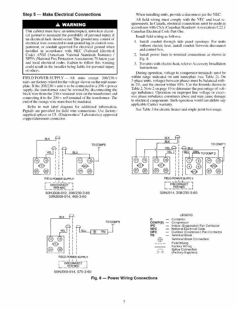
Step 5 -- Make Electrical Connections
Unit cabinet must have an uninterrupted, unbroken electri-cal ground to minimize the possibility of personal inju U ifan electrical fault should occm: This ground may consist ofelectrical wire connected to unit ground lug in control com-partment, or conduit approved for electrical ground wheninstalled in accordance with NEC (National Electric_dCode) ANSI (American National Standards Institute) /NFPA (National Fire Protection Association) 70-latest yetuand local electrical codes. Failure to follow this warningcould result in the installer being liable for personal inju Uof others.
FIELD POWER SUPPLY -- All units except 208/230-vunits are factory-wired for the voltage shown on the unit name-plate. If the 208/230-v unit is to be connected to a 208-v powersupply, the transformer must be rewired by disconnecting theblack wire from the 230-v terminal wire on the transformer and
connecting it to the 200-v red terminal of the transfonnel: Theend of the orange wire must then be insulated.
Refer to unit label diagram for additiomfl infonnation.Pigtails are provided for field wire connections. Use factory-supplied splices or UL (Underwriters' Laboratories) approvedcopper/_duminum connector
When inst_dling units, provide a disconnect per the NEC.
All field wiring must comply with the NEC and local re-quirements. In Canada, electrical connections must be made inaccor&mce with CSA (Canadian Stan&_rds Association) C22.1Canadian Electric_d Code Part One.
Install field wiring as follows:
1. Inst_dl conduit through side panel openings. For unitswithout electric heat, install conduit between disconnectand control box.
2. Inst_dl power lines to terminal connections as shown inFig. 8.
3. For units with electric heat, refer to Accessory InstallationInstructions.
During operation, voltage to compressor terminals must bewithin range indicated on unit nmneplate (see Table 2). On3-phase units, voltages between phases must be balanced with-in 2%, and the current within 10%. Use the formula shown inTable 2, Note 2 on page 10 to determine the percentage of volt-age imbalance. Operation on improper line voltage or exces-sive phase imbalance constitutes abuse and may cause damageto electric_d components. Such operation would inv_didate anyapplicable Cturier warranty.
See Table 3 for electric heater and single point box usage.
BLK @
TO COMPS
BLU
FIELD POWER SUPPLYI j, L
[ DISCONNECT li I[ PER NEC j
50HJ008-012, 208/230-3-6050HJ008-014, 460-3-60
BLK @BLK Ii
j YEL _ I
TO COMP 1
BLU
FIELD POWER SUPPLYt t t
r 1I DISCONNECT IL PER NEC ._j
50H J014, 208/230-3-60
TO COMPS
(D TB2 j
C
COMP(S) --IFCNECOFCTB
@
FIELD POWER SUPPLY
F 3I DISCONNECT IL PER NEC _d
50HJ008-014,575-3-60
Fig. 8 -- Power Wiring Connections
LEGEND
ContactorCompressorIndoor (Evaporator) Fan ContactorNational Electrical CodeOutdoor (Condenser) Fan ContactorTerminal BlockTerminal Block Connection
Field WiringFactory WiringSplice Connection(Factory-Supplied)

UNIT NOMINAL IFMV-PH-Hz TYPE
STD
206/230-3-60
HIGHSTATIC
STD60HJO08
460-3-60
HIGHSTATIC
STD
575-3-60
HIGHSTATIC
STD
208/230-3-60
HIGHSTATIC
60HJO09
STD
460-3-60
HIGHSTATIC
See page 10 for legend and notes.
Table 2 -- Electrical Data
VOLTAGE COMP NO. 1 COMP NO. 2 ELECTRIC HEATERRANGE
CONV OFM OFM IFM
OUTLET Min Max RLA LRA RLA LRA OTY FLA FLA NominalkW* FLA
NO 187 254 12.4 88.0 12.4 88.0 2
7.8/10.4
1.4 7.5 12.0/16.016.6/24.8
24.0/32.031.8/42.4
YES 187 254 12.4 88.0 12.4 88.0 2
7.8/10.4
1.4 7.5 12.0/16.016.6/24.6
24.0/32.031.8/42.4
NO 167 254 12.4 88.0 12.4 88.0 2
718/1014
1.4 10.6 12.0/16.018.6/24.8
24.0/32.031.8/42.4
YES 167 254 12.4 88.0 12.4 88.0 2
7.8/10.4
1.4 10.6 12.0/16.016.6/24.8
24.0/32.031.8/42.4
NO 414 508 6.4 44.0 6.4 44.0 2 0.7 3.4
13.9
16.527.8
33.041.7
YES 414 508 6.4 44.0 6.4 44.0 2 0.7 3.4
13.9
16.527.8
33.041.7
NO 414 508 6.4 44.0 6.4 44.0 2 0.7 4.8
13.9
16.527.8
33.041.7
YES 414 508 6.4 44.0 6.4 44.0 2 0.7 4.8
13.9
16.527.8
33.041.7
NO 518 632 4.8 34.0 4.8 34.0 2 0.7 3.4 17.0
34.0
YES 518 632 4.8 34.0 4.8 34.0 2 0.7 3.4 17.034.0
NO 518 632 4.8 34.0 4.8 34.0 2 0.7 4.8 17.0
34.0
YES 518 632 4.8 34.0 4.8 34.0 2 0.7 4.8 17.0
34.0
NO 167 254 13.4 105.0 13.1 105.0 2
7.8/10.4
1.4 7.5 12.0/16.018.6/24.8
24.0/32.031.8/42.4
YES 187 254 13.4 105.0 13.1 105.0 2
718/1014
1.4 7.5 12.0/16.018.6/24.8
24.0/32.031.8/42.4
NO 167 254 13.4 105.0 13.1 105.0 2
718/1014
1.4 10.6 12.0/16.018.6/24.8
24.0/32.031.8/42.4
YES 167 254 13.4 105.0 13.1 105.0 2
7.8/10.4
1.4 10.6 12.0/16.016.6/24.8
24.0/32.031.8/42.4
POWER SUPPLY DISCONNECT
Fuse SlZEf
orMCA HACR MOCP FLA LRA
-- -- 21.513.9 16.7 25.1
NO 414 508 7.4 55.0 7.4 55.0 2 0.7 3.4 16.5 19.8 29.127.8 33.4 46.0
33.0 39.7 53.941.7 50.2 66.9
-- -- 24.213.9 16.7 28.5
YES 414 508 7.4 55.0 7.4 55.0 2 0.7 3.4 16.5 19.8 31.827.8 33.4 48.7
33.0 39.7 56.641.7 50.2 69.6
-- -- 22.913.9 16.7 26.9
NO 414 508 7.4 55.0 7.4 55.0 2 0.7 4.8 16.5 19.8 30.827.8 33.4 47.8
33.0 39.7 55.641.7 50.2 68.7
-- -- 25.613.9 16.7 30.3
YES 414 508 7.4 55.0 7.4 55.0 2 0.7 4.8 16.5 19.8 33.527.8 33.4 50.5
33.0 39.7 58.341.7 50.2 71.4
-- 40/ 40 242/242-- 40/ 40 242/242
-- 47/ 53 242/24280/ 90 68/ 77 242/242
100/110 85/ 97 242/242125/150 110/126 242/242
-- 46/ 46 247/247-- 46/ 46 247/247
60/ 70 53/ 58 247/24780/ 90 74/ 83 247/247
100/125 91/103 247/247125/150 116/131 247/247
-- 44/ 44 267/267-- 44/ 44 267/267
60/ 70 51/ 56 267/26780/ 90 72/ 81 267/267
100/110 89/101 267/267125/150 114/129 267/267
-- 49/ 49 271/271-- 49/ 49 271/271
70/ 70 56/ 62 271/27190/100 77/ 86 271/271
110/125 94/106 271/271150/150 119/135 271/271
-- 20 121-- 23 121
-- 27 121-- 42 121
-- 50 12170 62 121
-- 23 123-- 26 123
-- 29 123-- 45 123
-- 52 12370 64 123
-- 22 133-- 25 134
-- 28 134-- 44 134
-- 51 13470 63 134
-- 24 135-- 27 136
-- 31 136-- 46 136
-- 54 13680 66 136
-- 15 94-- 22 95
-- 41 95
-- 17 96
-- 24 96-- 43 96
-- 17 104-- 23 104
-- 42 104
-- 19 106
-- 25 106-- 44 106
-- 42/ 42 276/276-- 42/ 42 276/276
-- 47/ 53 276/27680/ 90 68/ 77 276/276
100/110 85/ 97 276/276110/150 110/126 276/276
-- 48/ 48 281/281-- 48/ 48 281/281
60/ 70 53/ 58 281/28180/ 90 74/ 83 281/281
100/125 91/103 281/281125/150 116/131 281/281
-- 46/ 46 301/301-- 46/ 46 301/301
60/ 70 51/ 56 301/30180/ 90 72/ 81 301/301
100/110 89/101 301/301125/150 114/129 301/301
-- 51/ 51 305/305-- 51/ 51 305/305
-- 70/ 70 56/ 62 305/305-- 90/100 77/ 86 305/305
-- 110/125 94/106 305/305-- 150/150 119/135 305/305
20 -- 23 14320 -- 23 143
20 -- 27 14350 -- 42 143
60 -- 50 143-- 70 62 143
20 -- 25 14520 -- 26 145
35 -- 29 14550 -- 45 145
60 -- 52 145-- 70 64 145
20 -- 24 15520 -- 25 156
35 -- 28 15650 -- 44 156
60 -- 51 156-- 70 63 156
20 -- 27 15735 -- 27 158
35 -- 31 15860 -- 46 158
60 -- 54 158-- 80 66 158
Bkr
--/-- 38.2/ 38.2 45/4521.7/ 25.0 38.2/ 40.6 45/45
33.4/ 38.5 51.1/ 57.5 60/6051.7/ 59.7 74.0/ 84.0 --
66.7/ 77.0 92.8/105.6 --88.4/102.0 119.9/136.9 --
--/-- 44.2/ 44.2 50/5021.7/ 25.0 44.2/ 45.6 50/50
33.4/ 38.5 56.1/ 62.5 --51.7/ 59.7 79.0/ 89.0 --
66.7/ 77.0 97.8/110.6 --88.4/102.0 124.9/141.9 --
--/-- 41.3/ 41.3 45/4521.7/ 25.0 41.3/ 44.5 50/50
33.4/ 38.5 54.9/ 61.4 --51.7/ 59.7 77.9/ 87.8 --
66.7/ 77.0 96.6/109.5 --88.4/102.0 123.7/140.8 --
--/-- 47.3/ 47.3 50/5021.7/ 25.0 47.3/ 49.5 60/60
33.4/ 38.5 59.9/ 66.4 --51.7/ 59.7 82.9/ 92.8 --
66.7/ 77.0 101.6/114.5 --88.4/102.0 128.7/145.8 --
-- 19.2 2016.7 25.1 20
19.8 29.1 2033.4 46.0 50
39.7 53.9 6050.2 66.9 --
-- 21.9 2016.7 28.5 20
19.8 31.8 3533.4 48.7 50
39.7 56.6 6050.2 69.6 --
-- 20.6 2016.7 26.9 20
19.8 30.8 3533.4 47.8 50
39.7 55.6 6050.2 68.7 --
-- 23.3 2016.7 30.3 35
19.8 33.5 3533.4 50.5 60
39.7 58.3 6050.2 71.4 --
-- 14.6 2016.4 23.8 20
32.7 44.3 45
-- 16.8 20
16.4 26.5 2032.7 44.3 45
-- 15.8 2016.4 25.2 20
32.7 45.7 50
-- 17.9 20
16.4 27.9 2032.7 45.7 50
--/-- 40.2/ 40.2 45/4521.7/ 25.0 40.2/ 40.6 45/45
33.4/ 38.5 51.1/ 57.5 60/6051.7/ 59.7 74.0/ 84.0 --
66.7/ 77.0 92.8/105.6 --88.4/102.0 119.9/136.9 --
--/-- 46.2/ 46.2 50/5021.7/ 25.0 46.2/ 46.2 50/50
33.4/ 38.5 56.1/ 62.5 --51.7/ 59.7 79.0/ 89.0 --
66.7/ 77.0 97.8/110.6 --88.4/102.0 124.9/141.9 --
--/-- 43.3/ 43.3 50/5021.7/ 25.0 43.3/ 44.5 50/50
33.4/ 38.5 54.9/ 61.4 --51.7/ 59.7 77.9/ 87.8 --
66.7/ 77.0 96.6/109.5 --88.4/102.0 123.7/140.8 --
--/-- 49.3/ 49.3 60/6021.7/ 25.0 49.3/ 49.5 60/60
33.4/ 38.5 59.9/ 66.451.7/ 59.7 82.9/ 92.8
66.7/ 77.0 101.6/114.588.4/102.0 128.7/145.8

Table 2 -- Electrical Data (cont)
UNIT
5OH J009
(cont)
50HJ012
50HJ014
VOLTAGE COMP NO. 1 COMP NO, 2 ELECTRIC HEATERRANGE
NOMINAL IFM CONV OFM OFM IFM
V-PH-Hz TYPE OUTLET OTY FLA FLA Nominal FLAMin Max RLA LRA RLA LRA kW*
575-3-60
208/230-3-60
460-3-60
575-3-60
NO 518 632 6.4 44.0 6.4 44.0 2 0.7 3.4 17J_
STD 34.0
YES 518 632 6.4 44.0 6.4 44.0 2 0.7 3.4 17J_
34.0
NO 518 632 6.4 44.0 6.4 44.0 2 0.7 3.4 17J_
HIGH 34.0STATIC
YES 518 632 6.4 44.0 6.4 44.0 2 0.7 4.8 17-J_
34.0
POWER SUPPLY DISCONNECT
Fuse SIZEt
or MOCPMCA HACR FLA LRA
Bkr
-- 18.2 20 -- 19 11416.4 23.8 20 -- 22 115
32.7 44.3 45 -- 41 115
-- 20.4 25 -- 21 116
16.4 26.5 25 -- 24 11632.7 46.9 50 -- 43 116
-- 18.2 20 -- 19 11416.4 23.8 20 -- 22 115
32.7 44.3 45 -- 41 115
-- 21.5 25 -- 22 126
16.4 27.9 25 -- 25 12632.7 48.3 50 -- 44 126
--/-- 53.0/ 53.0 60/60 -- 56/ 56 341/341
208/230-3-60 STD
460-3-60 STD
575-3-60 STD
7.8/10.4 21.7/ 25.0 53.0/ 53.0 60/60 -- 56/ 56 341/341
NO 187 254 17.6 125.0 17.6 125.0 2 1.4 10.6 12.0/16.0 33.4/ 38.5 54.9/ 61.4 -- 60/ 70 56/ 56 341/34124.0/32.0 66.7/ 77.0 96.6/109.5 -- 100/110 89/101 341/341
31.8/42.4 88.4/102.0 123.7/140.8 -- 125/150 114/129 341/341
STD 37.5/50.0 104.2/120.3 143.5/133.5 -- 150/150 132/151 341/341
-- --/-- 59.0/ 59.0 70/70 -- 61/ 61 345/3457.8/10.4 21.7/ 25.0 59.0/ 59.0 -- 70/ 70 61/ 61 345/345
YES 187 254 17.6 125.0 17.6 125.0 2 1.4 10.6 12.0/16.0 33.4/ 38.5 59.9/ 66.4 -- 70/ 70 61/ 62 345/34524.0/32.0 66.7/ 77.0 101.6/114.5 -- 110/125 94/106 345/345
31.8/42.4 88.4/102.0 128.7/145.8 -- 150/150 119/135 345/34537.5/50.0 104.2/120.3 148.5/137.5 -- 150/150 138/156 345/345
-- --/-- 57.4/ 57.4 70/70 -- 61/ 61 364/3647.8/10.4 21.7/ 25.0 57.4/ 57.4 -- 70/ 70 61/ 61 364/364
NO 187 254 17.6 125.0 17.6 125.0 2 1.4 15.0 12.0/16.0 33.4/ 38.5 60.4/ 66.9 -- 70/ 80 61/ 62 364/36424.0/32.0 66.7/ 77.0 102.1/115.0 -- 110/125 94/106 364/364
31.8/42.4 88.4/102.0 129.2/146.3 -- 150/150 119/135 364/364HIGH 37.5/50.0 104.2/120.3 149.0/139.0 -- 150/175 137/156 364/364
STATIC __ --/-- 63.4/ 63.4 70/70 -- 66/ 66 369/369
7.8/10.4 21.7/ 25.0 63.4/ 63.4 -- 70/ 70 66/ 66 369/369
YES 187 254 17.6 125.0 17.6 125.0 2 1.4 15.0 12.0/16.0 33.4/ 38.5 65.4/ 71.9 -- 80/ 80 66/ 67 369/36924.0/32.0 66.7/ 77.0 107.1/120.0 -- 110/125 99/111 369/369
31.8/42.4 88.4/102.0 134.2/151.3 -- 150/175 124/140 369/36937.5/50.0 104.2/120.3 154.0/143.0 -- 175/175 143/161 369/369
-- -- 24.9 20 -- 26 17013.9 16.7 26.9 20 -- 26 171
NO 414 508 8.3 62.5 8.3 62.5 2 0.7 4.8 16.5 19.8 30.8 35 -- 28 17133.0 39.7 55.6 60 -- 51 171
41.7 50.2 68.7 -- 70 63 171
STD 50.0 60.1 66.1 -- 80 75 171
-- -- 27.6 20 -- 29 17213.9 16.7 30.3 35 -- 29 173
YES 414 508 8.3 62.5 8.3 62.5 2 0.7 4.8 16.5 19.8 33.5 35 -- 31 17333.0 39.7 58.3 60 -- 54 173
41.7 50.2 71.4 -- 80 66 17350.0 60.1 70.1 -- 80 77 173
-- -- 27.5 20 -- 28 18213.9 16.7 30.1 35 -- 29 182
NO 414 508 8.3 62.5 8.3 62.5 2 0.7 7.4 16.5 19.8 34.1 40 -- 31 18233.0 39.7 58.9 60 -- 54 182
41.7 50.2 71.9 -- 80 66 182HIGH 50.0 60.1 69.4 -- 80 78 182
STATIC __ __ 30.2 35 -- 32 184
13.9 16.7 33.5 40 -- 32 184
YES 414 508 8.3 62.5 8.3 62.5 2 0.7 7.4 16.5 19.8 36.8 40 -- 34 18433.0 39.7 61.6 -- 70 57 184
41.7 50.2 74.6 -- 80 69 18450.0 60.1 73.4 -- 80 80 184
-- -- 19.1 25 -- 20 136
NO 518 632 6.3 50.0 6.3 50.0 2 0.7 4.8 17.0 16.4 25.2 25 -- 23 13634.0 32.7 45.7 50 -- 42 136
STD 51.0 49.1 53.9 60 -- 61 136
-- -- 21.3 25 -- 22 138
YES 518 632 6.3 50.0 6.3 50.0 2 0.7 4.8 17.0 16.4 27.9 25 -- 25 13834.0 32.7 48.3 50 -- 44 13851.0 49.1 56.5 60 -- 63 138
-- -- 21.2 25 -- 23 145
NO 518 632 6.3 50.0 6.3 50.0 2 0.7 7.4 17.0 16.4 27.8 25 -- 26 14634.0 32.7 48.3 50 -- 44 146
HIGH 51.0 49.1 56.5 -- 70 63 146
STATIC __ __ 23.4 25 -- 25 147
YES 518 632 6.3 50.0 6.3 50.0 2 0.7 7.4 17.0 16.4 30.5 35 -- 28 14834.0 32.7 50.9 60 -- 46 14851.0 49.1 59.1 -- 70 65 148
-- --/-- 60.6/ 60.6 70/70 -- 64/ 64 426/4267.8/10.4 21.7/ 25.0 60.6/ 60.6 -- 70/ 70 64/ 64 426/426
NO 187 254 19.0 156.0 19.0 156.0 2 1.4 15.0 12.0/16.0 33.4/ 38.5 60.4/ 66.9 -- 70/ 80 64/ 64 426/42624.0/32.0 66.7/ 77.0 102.1/115.0 -- 110/125 94/106 426/426
31.8/42.4 88.4/102.0 129.2/146.3 -- 150/150 119/135 426/42637.5/50.0 104.2/120.3 149.0/139.0 -- 150/175 137/156 426/426
-- --/-- 66.6/ 66.6 70/70 -- 70/ 70 431/4317.8/10.4 21.7/ 25.0 66.6/ 66.6 -- 70/ 70 70/ 70 431/431
YES 187 254 19.0 156.0 19.0 156.0 2 1.4 15.0 12.0/16.0 33.4/ 38.5 65.4/ 71.9 -- 80/ 80 70/ 70 431/43124.0/32.0 66.7/ 77.0 107.1/120.0 -- 110/125 99/111 431/431
31.8/42.4 88.4/102.0 134.2/151.3 -- 150/175 124/140 431/43137.5/50.0 104.2/120.3 154.0/143.0 -- 175/175 143/161 431/431
-- -- 29.1 35 -- 31 19713.9 16.7 30.1 35 -- 31 197
NO 414 508 9.0 70.0 9.0 70.0 2 0.7 7.4 16.5 19.8 34.1 40 -- 31 19733.0 39.7 58.9 60 -- 54 197
41.7 50.2 71.9 -- 80 66 19750.0 60.1 69.4 -- 80 78 197
-- -- 31.8 35 -- 33 19913.9 16.7 33.5 40 -- 33 199
YES 414 508 9.0 70.0 9.0 70.0 2 0.7 7.4 16.5 19.8 36.8 40 -- 34 19933.0 39.7 61.6 -- 70 57 199
41.7 50.2 74.6 -- 80 69 19950.0 60.1 73.4 -- 80 80 199
-- -- 23.7 30 -- 25 153
NO 518 632 7.4 54.0 7.4 54.0 2 0.7 7.4 17.0 16.4 27.8 30 -- 26 15434.0 32.7 48.3 50 -- 44 15451.0 49.1 56.5 -- 70 63 154
-- -- 25.9 30 -- 27 155
YES 518 632 7.4 54.0 7.4 54.0 2 0.7 7.4 17.0 16.4 30.5 35 -- 28 15534.0 32.7 50.9 60 -- 46 15551.0 49.1 59.1 -- 70 65 155
See page 10 for legend and notes.

LEGEND AND NOTES FOR TABLE 2
LEGEND
FLA -- Full Load AmpsHACR -- Heating, Air Conditioning and RefrigerationIFM Indoor (Evaporator) Fan MotorLRA -- Locked Rotor AmpsMCA -- Minimum Circuit AmpsMOCP -- Maximum Overcurrent ProtectionNEC -- National Electrical Code
OFM -- Outdoor (Condenser) Fan MotorRLA Rated Load Amps
*Heater capacity (kW) is based on heater voltage of 208, 240, 480, and 575-v. Ifpower distribution voltage varies from rated heater voltage, heater kW will varyaccordingly.
1-Used to determine minimum disconnect per NEC.
NOTES:1. In compliance with NEC requirements for multimetor and combination load
equipment (refer to NEC Articles 430 and 440), the evercurrent protectivedevice for the unit shall be fuse or HACR breaker.
2. Unbalanced 3-Phase Supply VoltageNever operate a motor where a phase imbalance in supply voltage is greaterthan 2%. Use the following formula to determine the percent of voltageimbalance.
% Voltage Imbalance
max voltage deviation from average voltage= 100x
average voltage
Example: Supply voltage is 460-3-60.
C US
AB=452vBC = 464 vAC = 455 v
Average Voltage = 452 + 464 + 4553
1371=--
3
= 457
Determine maximum deviation from average voltage.(AB) 457 - 452 = 5 v(BC) 464 - 457 = 7 v(AC) 457 - 455 = 2 v
Maximum deviation is 7 v.
Determine percent of voltage imbalance.
7% Voltage Imbalance = 100 x 45"_'_-
= 1.53%
This amount of phase imbalance is satisfactory as it is below the maximumallowable 2%.
I IMPORTANT: If the sup£1y voltage phase imbalance is more than 2%, con- Itact your local electric utility company immediately. I3. Non-fused disconnect switch cannot be used when rooftop unit electrical rat-
ings exceed 80 amps.
Table 3 -- Electric Heater Usage
ACCESSORY HEATER ACCESSORY SINGLE POINT BOXUNIT VOLTAGE ACCESORY PART NUMBER PART NUMBER50HJ (60 Hz) kW CRHEATER---A00 CRSINGLE---A00
7.8/ 9.6/10.4 017 006
208/230/240 12.0/14.7/16.0 010 006
(3 phase) 18.6/22.8/24.8 011 00724.0/29.4/32.0 012 00731.8/39.0/42.4 012+017 009
008 12.8/13.9 016 006480/480 15.2/16.5 013 006(3 phase) 25.6/27.8 014 006
30.4/33.0 015 00638.4/41.7 014+018 008
575 17.0 018 006(3 phase) 34.0 019 006
7.8/ 9.6/10.4 017 011
208/230/240 12.0/14.7/16.0 010 011
(3 phase) 18.6/22.8/24.8 011 01224.0/29.4/32.0 012 01231.8/39.0/42.4 012+017 015
009 12.8/13.9 016 011480/480 15.2/16.5 013 011(3 phase) 25.6/27.8 014 011
30.4/33.0 015 01138.4/41.7 014+018 014
575 17.0 018 011(3 phase) 34.0 019 011
7.8/ 9.6/10.4 017 011
208/230/240 12.0/14.7/16.0 010 012
(3 phase) 24.0/29.4/32.0 012 01231.8/38.9/42.4 012+017 01537.5/46.0/50.0 010+012 015
12.8/13.9 016 011012 480/480 15.2/16.5 013 011
(3 phase) 30.4/33.0 015 01138.4/41.7 014+018 01446.0/50.0 013+015 014
575 17.0 018 011(3 phase) 34.0 019 011
51.0 018+019 014
7.8/ 9.6/10.4 017 012
208/230/240 12.0/14.7/16.0 010 012(3 phase) 24.0/29.4/32.0 012 012
31.8/38.9/42.4 012+017 01537.5/46.0/50.0 010+012 015
12.8/13.9 016 011
014 480/480 15.2/16.5 013 011
(3 phase) 30.4/33.0 015 01138.4/41.7 014+018 01446.0/50.0 013+015 014
575 17.0 018 011
(3 phase) 34.0 019 01451.0 018+019 014
NOTES:
1. The rated heater voltage is 240, 480, and 575 v. If power distribution voltage varies from rated heater voltage, heater kW vary accordingly.2. To determine heater kW at voltages other than those shown in table, use the following formula:
Heater kW new = Heater kW rated x (unit power distribution voltage / rated heater voltage) 2As an example:For a 16 kW heater rated at 240 v with a power distribution voltage of 215 vkW new = 16 kW (215/240) 2kW new = 12.8 kW (rating at 215 v)
10

FIELD CONTROL WIRING-- Install a Cartier-approvedaccessory thermostat assembly according to installationinstructions included with the accessory. Ix_cate thennostatassembly on a solid wall in the conditioned space to sense aver-age temperature in accordance with thermostat installationinstructions.
Route thermostat cable or equivalent single leads of coloredwire from subbase terminals to low-voltage connections onunit (shown in Fig. 9A or9B) as described in Steps 1 through 4below.
NOTE: For wire runs up to 50 ft, use no. 18 AWG (AmericanWire Gage) insulated wire (35 C minimum). For 51 to 75 ft,use no. 16 AWG insulated wire (35 C minimum). For over75 ft, use no. 14 AWG insulated wire (35 C minimum). Allwire larger than no. 18 AWG cannot be directly connected tothe thermostat and will require a junction box and splice at thethermostat.
1. If mounted on a roof curb and electric¢fl power is to berun through the basepan, an accessory thru-the-bottomconnection kit is required. This is available through theloc_fl C_urier distributol: This kit is required to ensure areliable water-tight connection.
2. If unit is mounted on roof curb and accessory thin-the-bottom service connections are used, route wire throughconnections.
3. Pass control wires through the hole provided on unit (seeconnection D in Connection Sizes table in Fig. 7).
4. Feed wire through the raceway built into the corner postto the 24-v barrier located on the left side of the controlbox. See Fig. 10. The raceway provides the UL requiredcle_uance between the high-voltage and low-voltagewiring.
5. Connect thermostat wires to screw terminals of low-
voltage connector (see Fig. 9A or 9B).
NOTE: If thin-the-bottom power connections are used refer tothe accessory installation instructions for information on powerwiring. Refer to Fig. 7 for drilling holes in basepan.HEAT ANTICIPATOR SETTINGS -- For units with electricheat, set heat anticipator settings as shown in Table 4.
COOL STAGE 1
FAN
HEAT STAGE 1
COOL STAGE 2
HEAT STAGE 2
24 VAC HOT
24 VAC COM
N/A
OUTDOOR AIR
SENSOR
Y1/W2 - - - I - R
IG= - G
I
W/W1- - 7 I _ Y1
I IY/Y2 - - f - V - Y2
i
O/W2- _ _- -i- - W1I___1
R ...... J " W2
IPD/X
$1
S2
WIRECONNECTIONSTOLOW-VOLTAGESECTION(CONNECTIONBOARD)
THERMOSTAT DIPSWlTCH SETTINGS
ON
A B C D
LEGEND
Field Wiring
NOTE: Underlined letter indicates active thermostat output whenconfigured for A/C operation,
Fig. 9A -- Low-Voltage Connections(Standard Controls)
CONTROL
CONNECTION
BOARD
(_--24 VAC .... -,--,--,.?_',
_--RMTOCC--" ,_
CMPSAFE- "½
(_"-FSD .......... "
_"-SFS .............
NOT USED
THERMOSTAT CONTROL
CONN ECTION
BOARD
........
........
Fig. 9B -- Low Voltage Connections(Units with PremierLink TM Controls)
CONNECTIONBOARD
FACTORY-INSTALLEDDISCONNECT(OPTION)
RACEWAY
COMPRESSORNO, 2
COMPRESSORNO, 1
CONVENIENCEOUTLET(OPTION)
HOLE INENDPANEL
I
Fig. 10 -- Field Control Wiring Raceway
11

Table 4 -- Heat Anticipator Settings
UNIT
50HJ
208/230
ConfigurationHeater
2-StagekW* 1-Stage
Stage 1 Stage210.4, 16.0 0.3 NA NA
24.8, 32.0 0.6 0.3 0.3
42.4, 50.0 0.9 0.6 0.3
HeaterkW*
13.9, 16.5
27.8, 33.0
41.7, 50.0
UNIT VOLTAGE460
Configuration
2-Stage1-Stage
Stage 1 Stage2
0.3 NA NA
0.6 0.3 0.3
575
ConfigurationHeater
2-StagekW* 1-Stage
Stage 1 Stage 2
17.0, 34.0 0.3 NA NA
51.0 0.6 0.3 0.3
*Heater capacity (kW) is based on heater voltage of 240 v, 480 v or 575 v. If power distribution voltage to unit varies from ratedheater voltage, heater kW will vary accordingly.
Step 6 -- Adjust Factory-Installed OptionsHUMIDI-MIZER TM ADAPTIVE DEHUMIDIFICATION
SYSTEM -- Humidi-MiZer adaptive dehumidification system
operation can be controlled by field installation of a Cmrier-approved humidistat (Fig. 11). To install the humidistat:
NOTE: A light commercial Thennidistat TM control (Fig. 12)can be used instead of a humidistat if desired. The Thermidis-
tat control includes a thermostat find a humidistat. The humi-
distat is normally used in applications where a temperature
sensor is already provided (units wifll PremierLink TM control).
1. Route humidistat cable through hole provided in unit cor-
ner post.
2. Feed wires through the raceway built into the corner postto the 24-v bmrier located on the left side of the control
box. See Fig. 10. The raceway provides the UL-mquimd
clearance between high find low-voltage wiring.
3. Use a wire nut to connect humidistat cable into low-
voltage wiring as shown in Fig. 13.
To install a Thermidistat TM device:
1. Route Thermidistat cable through file hole provided in
unit comer post.
2. Feed the wires through the raceway built into the cornerpost to the 24-v barrier located on the left side of the con-
trol box. See Fig. 10. Tile raceway provides the UL-
required clearance between high and low voltage wiring.
3. A field-supplied relay must be installed between theThermidistat device and the Humidi-MiZer circuit
(recommended relay: HN612KK324). The relay coil isconnected between the DEHUM output find C (common)
of the unit. Refer to Fig. 14. The relay controls theHumidi-MiZer solenoid valve and must be wired be-
tween the Humidi-MiZer fuse and the low-pressureswitch. Refer to the installation instructions included with
the Cmrier Light Commercial Thermidistat device formore information.
DISCONNECT SWITCH -- The optional disconnect switch
is non-fused. The switch has the capability of being locked inplace for safety purposes.
Oo
,J
Fig. 11 -- Accessory Field-Installed Humidistat
7?
Fig. 12- Light Commercial Thermidistat Device
12

CBCRDHRDSVHRHULPSLSVLTLOTB
BLK BLU
_]RAN
CB _YEL
3.2 ._z,ff_-- RD --
LTL0 HR] L_•_:_ PNK_O-PNK_ (_ BRN BLK _BLK l
CR1 BRN--_T'-"i_u/k I I__pNK_ I r__v:o _ LSV2
LEGEND / / tt_'_ ORNtz_ORN-I
-- Circuit Breaker TRAN -- Transformer _"" T I_ ssv2-- Cooling Relay F_, Field S lice __BLU,--J i._-- Dehumidify Relay _ P / [ps2 J-- Discharge Solenoid Valve O Terminal (Unmarked) O"I_--BLU'_)'_O----BLU TB-- Heater Relay-- Humidistat • Splice _ooo+--
-- Low Pressure Switch Factory Wiring-- Liquid Solenoid Valve-- Low Temperature Lockout Field Control Wiring-- Terminal Block
Fig. 13 -- Typical Humidi-MiZer TM Adaptive Dehumidification SystemHumidistat Wiring (208/230-v Unit Shown)
LCT
_ IllTTTT
TTSrATWlRES
......
I R1
ROOF TOP UNIT
/
LEGEND
CB -- Circuit BreakerLCT -- Light Commercial Thermidistat TM DeviceLLSV -- Liquid Line Solenoid ValveLTLO -- Low Temperature Lockout
3.2 AMPS
PiNK, _ , _RE_D_ 24V
PINK L_J PINK . FROMHUMIDI-MIZERSYSTEMLLSV
HUMIDI-MIZERSYSTEM
Fig. 14 -- Typical Rooftop Unit with Humidi-MiZer Adaptive Dehumidification SystemWiring with Thermidistat Device
13

CONVENIENCE OUTLET -- An optional convenience out-let provides power for rooftop use. For maintenance personnelsafety, the convenience outlet power is off when the unit dis-connect is off. Adjacent unit outlets may be used for servicetools. An optional "Hot Outlet" is available from the factory asa special order item.
NOVAR CONTROLS -- Optional Novtu controls (ETM3051 ) are available for replacement or new construction jobs.MANUAL OUTDOOR-AIR DAMPER --The outdoor-airhood and screen are attached to the basepan at the bottom ofthe unit for shipping.
Assemblz;.:
1. Determine quantity of ventilation required for building.Record amount for use in Step 8.
2. Remove filter access panel by raising panel and swingingpanel outward. Panel is now disengaged from track andcan be removed. No tools are required to remove the filteraccess panel. Remove outdoor-tdr opening panel. Savepanels and screws. See Fig. 15.
3. Sepm'ate hood and screen from basepan by removing thescrews and brackets securing them. Save all screws anddiscard brackets.
4. Replace outdoor air opening panel.
5. Place hood on front of outdoor air opening panel. SeeFig. 16 for hood details. Secure top of hood with the6 screws removed in Step 3. See Fig. 17.
6. Remove and save 8 sclews (4 on each side) from sides ofthe manual outdoor-air dmnper
7. Align sclew holes on hood with screw holes on side ofmanual outdoor-air dampel: See Fig. 16 and 17. Securehood with 8 sclews from Step 6.
8. Adjust minimum position setting of the damper blade byadjusting the manu_d outdoor-air adjustment screws onthe front of the damper blade. Slide blade vertic_dly untilit is in the appropriate position detemfined by Fig. 18.Tighten screws.
9. Remove and save screws cunently on sides of hood. In-sert screen. Secure screen to hood using the screws. SeeFig. 17.
10. Replace filter access panel. Ensure filter access panelslides along the tracks and is securely engaged.
FILTERACCESSPANEL
OUTDOOR AirOPENINGPANEL
SCREWS(SIDE)
MANUALOUTDOOR-AIRADJUSTMENTSCREWS DAMPER
BLADE
Fig. 15 -- Damper Panel with ManualOutdoor-Air Damper Installed
HOOD TOP SCREWS(HIDDEN)
SCREWSSCREEN HOLDERS)
HOOD SIDES AND TOP-ASSEMBLED
HOODSIDE
Fig. 16- Outdoor-Air Hood Details
II[[tlllllll[t
Fig. 17 -- Optional Manual Outdoor-AirDamper with Hood Attached
PREMIERLIN K TM CONTROL -- The PmmierLink control-ler is compatible with Canier Comfort Network® (CCN) de-vices. This control is designed to allow users the access andability to change factory-defined settings, thus expanding thefunction of the standiud unit control board. Carder's diagnosticstandard tier display tools such as Navigato( r_'_or ScrollingMarquee can be used with the PremierLink controller
The PremierLink controller (see Fig, 19 and 20) requires theuse of a Cmrier electronic thermostat or a CCN connection fortime broadcast to initiate its internal timeclock. This is neces-sary for broadcast of time of day fimctions (occupied/ unoccu-pied). No sensors me supplied with the field-mounted Premier-Link control. The factory-installed PremierLink control in-cludes only the supply-air sensor (SAT) and the outdoor airtemperature sensor ((-)AT) as standmd. An indoor air quality(CO2) sensor can be added as an option. Refer to Table 5 forsensor usage. Refer to Fig. 21 for PremierLink controllerwiring. The PremierLink control may be mounted in thecontrol panel or an area below the control panel.
14

NOTE: PremierLink TM controller versions 1.3 and later am
shipped in Sensor mode. If used with a thermostat, the Pre-mierLink controller must be configured to Thennostat mode.
Install the Supply Air Temperature (SAT) Sensor -- When
the unit is supplied with a factory-mounted PremierLink con-
trol, the supply-air temperature (SAT) sensor (33ZCSENSAT)
is factory-supplied and wired. The wiring is muted from the
PmmierLink control over the control box, through a grommet,into the fan section, down _flong the back side of the fan, and
along the fan deck over to the supply-air opening.
The SAT probe is wire-tied to the supply-air opening (on the
horizontal opening end) in its shipping position. Remove the
sensor for installation. Re-position the sensor in the flange of
the supply-air opening or in the supply air duct (as required by
loc_fl codes). Drill or punch a I/2-in. hole in the flange or duct.
Use two field-supplied, self-drilling screws to secure the sensor
probe in a horizontal orientation.
NOTE: The sensor must be mounted in the dischmge airstmamdownstremn of the cooling coil and any heating devices. Be
sure the probe tip does not come in contact with any of the unitor heat surfaces.
Outdoor Air Temperature (OAT) Sensor -- When the unit is
supplied with a factory-mounted PmmierLink control, theoutdoor-air temperature (OAT) sensor is factory-supplied andwired.
Install the Indoor Air Quality (CO__) Sensor -- Mount the
optional indoor air quality (CO2) sensor according to manufac-
turer specifications.
1.0
0.8
LLIr¢D 0669
/////,/
0 2 4 8 10 12
_., 0.4
z 0.2
OUTDOOR AIRFLOW (cfm x 100)
Fig. 18 -- Outdoor Air Damper Position Setting
A separate field-supplied transformer must be used to pow-er the CO2 sensoc
Wire the CO2 sensor to the COM and IAQI terminals of J5on the PremierLink controllel: Refer to the PremierLink Instal-
lation, Start-up, and Configuration Instructions for detailedwiring and configuration information.
OUTPUTS
Fig. 19 -- PremierLink Controller
15

PREMIERLINK
CONTROL
©O
HINGEDDOORPANEL
( -;Fig. 20 -- PremierLink TM Controller (Installed)
Table 5 -- PremierLink Sensor Usage
OUTDOOR AIR RETURN AIR OUTDOOR AIR RETURN AIRAPPLICATION TEMPERATURE SENSOR TEMPERATURE SENSOR ENTHALPY SENSOR ENTHALPY SENSOR
Differential Dry Bulb
Temperature with Required --PremierLink* Included --(PremierLink HH79NZ017 33ZCT55SPT -- --
requires 4-20 mA or Equivalent
Actuator)
Single Enthalpy with
PremierLink* Included -- Required --(PremierLink Not Used -- HH57AC077 or --
requires 4-20 mA equivalentActuator)
Differential Enthalpywith PremierLink* Required -- Required --
(PremierLink Included -- -- HH57AC077 or HH57AC078 orrequires 4-20 mA Not Used equivalent equivalent
Actuator)
*PremierLink control requires Supply Air Temperature sensor 33ZCSENSAT andOutdoor Air Temperature sensor HH79NZ017 -- included with factory-installed PremierLink control;field-supplied and field-installed with field-installed PremierLink control.
NOTES:
1. CO2 Sensors (Optional):33ZCSENCO2 -- Room sensor (adjustable). Aspirator box is required for duct mounting of the sensor.33ZCASPCO2 -- Aspirator box used for duct-mounted CO2 room sensor.33ZCT55CO2 -- Space temperature and CO2 room sensor with override.33ZCT56CO2 -- Space temperature and CO2 room sensor with override and set point.
2. All units include the following Standard Sensors:Outdoor-Air Sensor -- 50HJ540569 -- Opens at 67 F, closes at 52 F, not adjustable.Mixed-Air Sensor- HH97AZ001 -- (PremierLink control requires Supply Air Temperature sensor 33ZCSENSATand Outdoor Air Temperature Sensor HH79NZ017)Compressor Lockout Sensor -- 50HJ540570 -- Opens at 35 F, closes at 50 R
]6

[ L BLK i
i REO, !
, i
RETURN AIRENTHALPY
SENSOR
BLK ..............................................................................................
LEGEND
COMMS -- CommunicationsOAT -- Outdoor Air Temperature SensorPWR -- Power
RTU -- Rooftop UnitSAT -- Supply Air Temperature SensorTB -- Terminal Block
7 ql_cBnN _._j
8 /]]_ X
RTU Terminal
Board
Fig. 21 -- Typical PremierLink TM Controls Wiring
Enthalpy Sensors and Control -- The enthfflpy control(HH57AC077) is supplied as a field-installed accessory to beused with the EconoMi$er2 damper control option. The out-door air enthalpy sensor is pall of file enfllalpy control. Theseparate field-installed accessory return air enthalpy sensor(HH57AC078) is required for differential enthalpy control.
NOTE: Tile enthalpy control must be set to the "D" setting fordiffelential enthalpy control to won properly.
The enthalpy control receives the indoor and returnenthalpy from the outdoor find return fdr enthalpy sensors findprovides a &y contact switch input to the PremierLink TM
controllel: Ix)cate the controller in place of an existing econo-mizer controller or near the actuator The mounting plate maynot be needed if existing bracket is used.
A closed contact indicates that outside air is preferred to thereturn all: An open contact indicates that file economizershould remain fit minimum position.
Outdoor Air Enthalpy Sensor/Enthalpy Controller(HH57AC077) -- To wile the outdoor air enthalpy sensor.perform file following (see Fig. 22 and 23):
NOTE: The outdoor air sensor can be removed from the backof file enthalpy controller and mounted remotely.
1. Use a 4-conductor. 18 or 20 AWG cable to connect theenthalpy control to the PlemierLink controller and powertransforme_:
2. Connect the following 4 wires from the wire harnesslocated in rooftop unit to the enthfdpy controller:
a. Connect the BRN wire to the 24 vac terminal (TRI)on enthalpy control and to pin 1 on 12-pin harness.
b. Connect the RED wire to the 24 vac GND terminal(TR) on enthalpy sensor and to pin 4 on 12-pinharness.
c. Connect the GRAY/ORN wire to J4-2 on Premier-Link controller and to terminal (3) on enthalpysensol:
d. Connect the GRAY/RED wire to J4-1 on Premier-Link controller and to terminal (2) on enthalpy sensol:
NOTE: If installing in a Carrier roollop, use the two gray wiresprovided from the control section to the economizer to connectPremierLink controller to termimds 2 and 3 on enthalpy sensol:
Return Air Enthalpy Sensor -- Mount the return-air enthalpysensor (HH57AC078) in the return-air duct. The return airsensor is wired to the enthalpy controller (HH57AC077). Theoutdoor enthalpy changeover set point is set fit the controllel:
To wire the return air enthalpy sensor, perform the follow-ing (see Fig. 22):
1. Use a 2-conductor, 18 or 20 AWC_ twisted pair cable toconnect the return air enthalpy sensor to the enthalpycontroller.
2. At the enthalpy control remove the factory-installedresistor from the (SR) find (+) terminals.
3. Connect the field-supplied RED wire to (+) spadeconnector on the return air enthfdpy sensor and the (SR+)terminal on file enthalpy controllel: Connect file BLKwire to (S) spade connector on the return air enthfdpysensor and the (SR) termimd on file enthalpy controllel:
17

ENTHALPY CONTROLLERRED
A(_C TR [-_ltRl[_- BRNsorh +[3SRi-h+D-iq
LED
I
GRAY/ORN
_WIRE HARNESS
GRAY/RED JIN UNIT
(OUTDOORIAIR
ENTHALPYBLK SENSOR)RED
[] S (RETURN AIR
[_ + ENTHALPY
m SENSOR
NOTES:1. Remove factory-installed jumper across SR and + before connecting
wires from return air sensor.2. Switches shown in high outdoor air enthalpy state. Terminals 2 and 3
close on low outdoor air enthalpy relative to indoor air enthalpy.3. Remove sensor mounted on back of control and locate in outside
airstream.
Fig. 22 -- Outdoor and Return Air Sensor WiringConnections for Differential Enthalpy Control
HH57AC077ENTHALPYCONTROLANDOUTDOOR AIRENTHALPY SENSOR
© O
HH57AC078 ENTHALPY SENSOR(USEDWITH ENTHALPYCONTROL FORDIFFERENTIAL ENTHALPYOPERATION)
÷'
€ €MOUNTING PLATE
4;
Fig. 23 -- Differential Enthalpy Control,Sensor and Mounting Plate (33AMKITENT006)
OPTIONAL ECONOMI$ER IV AND ECONOMI$ER2 --
See Fig. 24 for EconoMiSer IV component locations. SeeFig. 25 for EconoMi$er2 component locations.
NOTE: These instructions are for installing the optiomdEconoMi$er IV and EconoMiSer2 only. Refer to the accessoryEconoMiSer [V or EconoMi$er2 inst_fllation instructions whenfield installing an EconoMiSer IV or EconoMiSer2 accessory.
1. To remove the existing unit filter access panel, raise thepanel and swing the bottom outw_ud. Tile panel is nowdisengaged from the track and can be removed. SeeFig. 26.
2. The box with the economizer hood components isshipped in the compartment behind the economizet: TheEconoMiSer IV controller is mounted on top of theEconoMi$er IV in the position shown in Fig. 24. The op-tional EconoMiSer2 with 4 to 20 mA actuator signal con-trol does not include the EconoMiSer IV controller To te-move the component box from its shipping position, re-move the screw holding the hood box bracket to the topof the economizet: Slide the hood box out of the unit. SeeFig. 27.
IMPORTANT: If the power exhaust accessory is to be ]instzdled on the unit, the hood shipped with the unit will not Ibe used and must be discarded. Save the aluminum filterfor use in the power exhaust hood assembly.
[_ ECONOMI$ER IV
_------___ /'CONTROLLER
WlRING_J'_ / OUTSIDE AIR
HARNESS ^ _ / _TEMPERATURE SENSORLOW AMBIENTSENSOR
ACTUATOR__ i
....................................................................i 0
Fig. 24 -- EconoMi$er IV Component Locations
ECONOMI:PLUG
OUTDOORAIR HOOD
BRACKET
BAROMETRICRELIEFDAMPER
GEAR DRIVENDAMPER
Fig. 25 -- EconoMi$er2 Component Locations
FILTER ACCESS PANEL
INDOOR COIL ACCESS PANEL
Fig. 26 -- Typical Access Panel Locations
HOOD BOX
/
I ! 1/
// //
I/ 7t
lit /
i1 i t/
t ! ! 0
/t tt
i
Fig. 27 -- Hood Box Removal
18
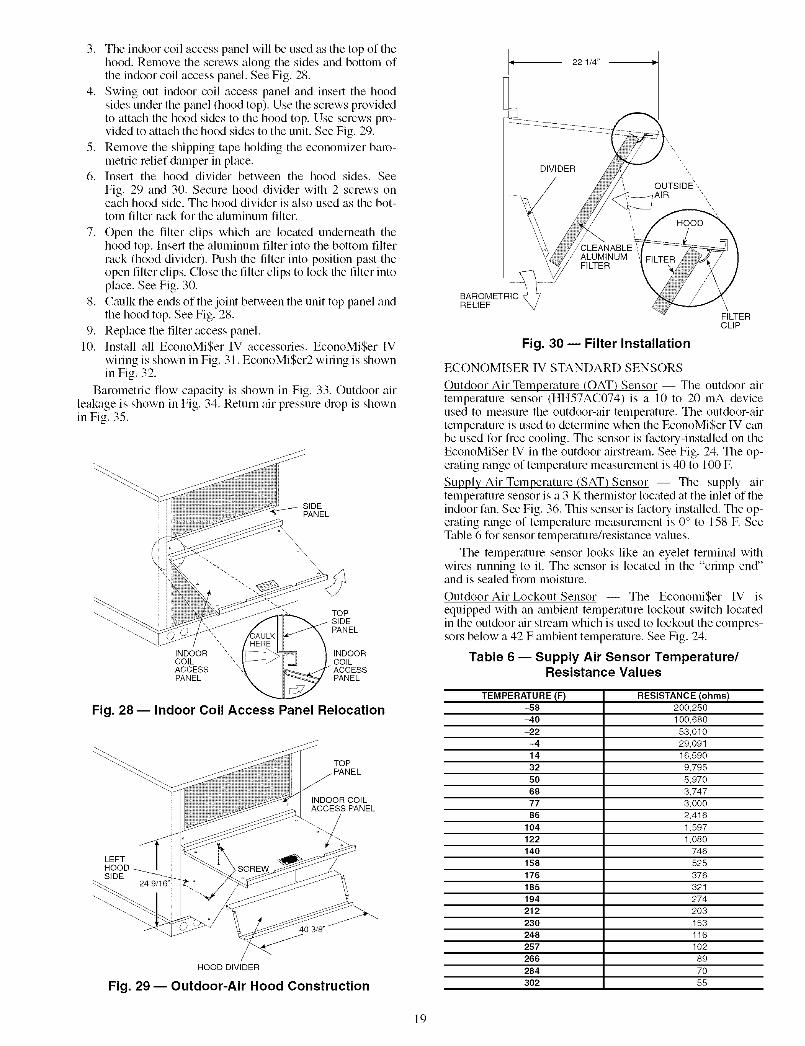
3. The indoor coil access panel will be used as the top of thehood. Remove the screws along the sides and bottom ofthe indoor coil access panel. See Fig. 28.
4. Swing out indoor coil access panel and insert the hoodsides under the panel (hood top). Use the sclews providedto attach the hood sides to the hood top. Use screws pro-vided to attach the hood sides to the unit. See Fig. 29.
5. Remove the shipping tape holding the economizer baro-metric relief &lmper in place.
6. Insert the hood divider between the hood sides. SeeFig. 29 and 30. Secure hood divider with 2 screws oneach hood side. The hood divider is also used as the bot-tom filter rock for file aluminum filter.
7. Open the filter clips which are located underneath thehood top. Insert the aluminum filter into the bottom filterrack (hood divider). Push file filter into position past theopen filter clips. Close the filter clips to lock file filter intoplace. See Fig. 30.
8. Caulk the ends of the joint between the unit top panel andthe hood top. See Fig. 28.
9. Replace the filter access panel.10. Install all EconoMi$er IV accessories. EconoMi$er IV
wiring is shown in Fig. 31. EconoMi$er2 wiring is shownin Fig. 32.
Barometric flow capacity is shown in Fig. 33. Outdoor airleakage is shown in Fig. 34. Return air pressure c_h-opis shownin Fig. 35.
SIDEPANEL
INDOORCOILACCESSPANEL
TOP
PANEL
INDOORCOIL
PANEL
Fig. 28 -- Indoor Coil Access Panel Relocation
LEFT
SIDE
TOP
/ PANEL/
INDOOR COILACCESS PANEL
HOOD DIVIDER
Fig. 29 -- Outdoor-Air Hood Construction
BAROMETRICRELIEF _/
ALUMINUMFILTER
Fig. 30 -- Filter Installation
FILTERCLIP
ECONOMISER IV STANDARD SENSORS
Outdoor Air Temperature (OAT) Sensor -- The outdoor airtemperature sensor (HH57AC074) is a 10 to 20 mA deviceused to measure the outdoor-air temperature. The outdoor-airtemperature is used to determine when the EconoMiSer IV canbe used for free cooling. The sensor is factory-installed on theEconoMi$er IV in the outdoor airstream. See Fig. 24. The op-erating range of temperature measurement is 40 to 100 E
Supply Air Temperature (SAT) Sensor -- The supply airtemperature sensor is a 3 K thermistor located at the inlet of theindoor fan. See Fig. 36. This sensor is factory installed. The op-erating range of temperature measurement is 0 ° to 158 E SeeTable 6 for sensor temperature/resistance values.
The temperature sensor looks like an eyelet terminal withwires running to it. The sensor is located in the "crimp end"and is sealed from moisture.
Outdoor Air Lockout Sensor -- The EconomiSer IV isequipped with an mnbient temperature lockout switch locatedin the outdoor air stream which is used to lockout the compres-sors below a 42 F ambient temperature. See Fig. 24.
Table 6 -- Supply Air Sensor Temperature/Resistance Values
TEMPERATURE (F) RESISTANCE (ohms)
-58 200,250
-40 100,680
-22 53,010
-4 29,091
14 16,590
32 9,795
50 5,970
68 3,747
77 3,000
86 2,416
104 1,597
122 1,080140 746
158 525
176 376
185 321
194 274
212 203
230 153
248 116
257 102
266 89
284 70
302 55
19

(FIELD
ACCESSORY]REMOTE M[_
POSITION POT
]AO S[NSOR
i
oar TEMP/ [
[NTBALPY SENSOR
B£K--RED--
(FIELO ACCESSORY)RAT/ERTHALPY SENSOR
LEGEND
DCV-- Demand Controlled VentilationIAQ -- Indoor Air QualityLA -- Low Ambient Lockout Device
OAT-- Outdoor-Air TemperaturePOT-- PotentiometerRAT-- Return-Air Temperature
FOR OCCUPANCY CONTROLREPLACE JUMPER WITH
/ FIELD-SUPPLIED TIME CLOCK
-- _ XH ZCO_OMISZR II 4 I I
:1TI MI} +
OP[_Pc1 ' ]- - - I [] MA> _
_SO{ _ [_j SE] YZL_
B C_ A_D _ FIELD SPL,CE
PL6-R
(NOT t_SEO}
_OT t_SEO]
FIELD SPLICE
TA_
TO PWR EXHAUSTACCESSORY
Potentiometer Defaults Settings:Power Exhaust MiddleMinimum Pos. Fully ClosedDCV Max. MiddleDCV Set MiddleEnthalpy C Setting
NOTES:
BRN 4_
(_OT USED}
GRY 5_
ORG 9_
1. 620 ohm, 1 watt 5% resistor should be removed only when using differentialenthalpy or dry bulb.
2. If a separate field-supplied 24 v transformer is used for the IAQ sensor powersupply, it cannot have the secondary of the transformer grounded.
3. For field-installed remote minimum position POT, remove black wire jumperbetween P and P1 and set control minimum position POT to the minimumposition.
Fig. 31 -- EconoMi$er IV Wiring
NOTE 1
NOTE3
J50HJ540573ACTUATORASSEMBLY
°RUN
DIRECT DRIVEACTUATOR
BLACK
500 OHM
RESISTOR'?
I
I
.o_1_I
+e- I
I
I
OPTIONAL 002SENSOR 4 - 20 mA
OUTPUT
IIIiI
.... J
VIOLET
PINK
RED
okU>-
WHITE
4
3
5
2
8
6
7
1
10
11
9
12
ECONOMISER2 PLUG
NOTES:1. Switch on actuator must be in run position for economizer to operate.2. PremierLinM M control requires that the standard 50HJ540569 outdoor-air sensor be replaced by either the CROASENRO01A00 dry bulb sen-
sor or HH57A077 enthalpy sensor.3. 50HJ540573 actuator consists of the 50HJ540567 actuator and a harness with 500-ohm resistor.
Fig. 32 -- EconoMi$er2 with 4 to 20 mA Control Wiring
20

2& 2500P_z 2000
1500o_
1000
_o500
i0
z o0.05 0.15 0.25
o,u_ STATIC PRESSURE (in. wg)
Fig. 33 -- Barometric Relief Flow Capacity
-- 30
25
20o_
15
kU
u_ 10
_om 5O
_z 00.13 0.20 0.22 0.25 0.30 0.35 0.40 0.45 0.50
O STATIC PRESSURE (in. wg)Lt-
Fig. 34 -- Outdoor Air Damper Leakage
6000 _
3o00 :: ::© 2000
lOO_z
0 ' i , i , r , i , r , i , i
jO 0.05 0.10 0.15 0.20 0.25 0.30 0.35u_
STATIC PRESSURE (in. wg)
Fig. 35 -- Return Air Pressure Drop
SUPP_ AIRTEMPERATURESENSORMOUNTINGLOCATION
SUPPLY AIRTEMPERATURESENSOR
Fig. 36 -- Supply Air Sensor Location
21
ECONOMISER IV CONTROL MODES
IMPORTANT: The optional EconoMiSer2 does notinclude a controllec The EconoMiSer2 is operated by a 4 to20 mA sign_fl from an existing field-supplied controller(such as PremierLink TM control). See Fig. 32 for wiringinformation.
Determine the EconoMiSer IV control mode before set up ofthe control. Some modes of operation may require different sen-sors. Refer to Table 7. The EconoMiSer IV is supplied from thefactoly with a supply air temperature sensor and an outdoor airtemperature sensor This allows for operation of theEconoMiSer IV with outdoor air dry bulb changeover control.Additional accessories can be added to allow for different typesof changeover control and operation of the EconoMiSer IV andunit.
Table 7 -- EconoMi$er IV Sensor Usage
APPLICATION
Outdoor AirDry Bulb
DifferentialDry Bulb
Single Enthalpy
DifferentialEnthalpy
CO2 for DCVControl using aWall-MountedCO2 SensorCO2 for DCV
Control using aDuct-MountedCO2 Sensor
ECONOMI$ER IV WITH OUTDOOR AIRDRY BULB SENSOR
Accessories Required
None. The outdoor air dry bulb sensoris factory installed.
CRTEMPSN002A00*
HH57AC078
HH57AC078and
CRENTDIF004A00*
33ZCSENCO2
33ZCSENCO21- I_ Iand CRCBDIOX005A001-t
33ZCASPCO2**
*CRENTDIF004A00 and CRTEMPSN002A00 accessories are used onmany different base units. As such, these kits may contain parts thatwill not be needed for installation.
t33ZCSENCO2 is an accessory CO2 sensor.**33ZCASPCO2 is an accessory aspirator box required for duct-
mounted applications.1-tCRCBDIOX005A00 is an accessory that contains both 33ZCSENCO2
and 33ZCASPCO2 accessories.
Outdoor DLy Bulb Changeover -- The standard controller isshipped from the facto/'?" configured for outdoor chy bulbchangeover control. The outdoor air and supply air temperaturesensors tue included as stan&ud. For this control mode, theoutdoor temperature is compared to an adjustable set pointselected on the control. If the outdoor-air temperature is abovethe set point, the EconoMiSer IV will adjust the outdoor air&Lmpers to minimum position. If the outdoor-air temperature isbelow the set point, the position of the outdoor air dampers willbe controlled to provide free cooling using outdoor _dc Whenin this mode, the LED next to the free cooling set point potenti-ometer will be on. The changeover temperature set point iscontrolled by the flee cooling set point potentiometer locatedon the control. See Fig. 37. The sc_de on the potentiometer is A,B, C, and D. See Fig. 38 for the corresponding temperaturechangeover values.
Differential Dry Bulb Control -- For differential dry bulbcontrol the standard outdoor chy bulb sensor is used in conjunc-tion with an additional accessory dry bulb sensor (part numberCRTEMPSN002A00). The accessoq sensor must be mountedin the return airstream. See Fig. 39. Wiring is provided in theEconoMiSer IV wiring haness. See Fig. 31.
In this mode of operation, the outdoor air temperature iscompared to the return air temperature and the lower tempera-ture air stream is used for cooling. When using this mode ofchangeover control, turn the enthalpy setpoint potentiometerfully clockwise to the D setting. See Fig. 37.

FAN SET POINT
WHEN EXHAUSTCONTACT IS MADE
POSITION SETTING
DEMAND CONTROLVENTILATION SET POINT
LED LIGHTSDEMAND CONTROL
VENTILATION INPUTIS ABOVE SET POINT
VENTILATION SET POINT
LED LIGHTS WHENOUTDOOR AIR IS
SUITABLE FOR
FREE COOLINGENTHALPY
CHANGEOVER SET POINT
Fig. 37 -- EconoMi$er IV Controller Potentiometerand LED Locations
19I
LED ON
18-17
] 6- -- - LED OFF
15
<E14
13
12
11
10
94O
LED ON
LED O;
45 50 55 60 65 70 75 80
DEGREES FAHRENHEIT
LED ON- --
LED OFF _%._I
85 90 95 100
Fig. 38 -- Outdoor Air Temperature ChangeoverSet Points
ECONOMI$ER_
ECONOMI$ERR7
y CONTROLLER
Fig. 39 -- Return Air Temperature orEnthalpy Sensor Mounting Location
Outdoor Enthalpy Changeover -- For enthalpy control, ac-cessory enth_dpy sensor (part number HH57AC078) is re-quired. Replace the standard outdoor dry bulb temperature
sensor with the accessory enthalpy sensor in the same mount-ing location. See Fig. 24. When the outdoor air enth_dpy risesabove the outdoor enthalpy changeover set point, the outdoor-air damper moves to its minimum position. The outdoorenthalpy changeover set point is set with the outdoor enth_dpyset point potentiometer on the EconoMi$er [V controllel: Theset points are A, B, C, and I). See Fig. 40. The factory-installed620-ohln jumper must be in place across terminals SR and SR+on the EconoMiSer IV controllel: See Fig. 24 and 41.
Differential Enthalpy Control -- For differential enth_dpycontrol, the EconoMiSer IV controller uses two enthalpy sen-sors (HH57AC078 and CRENTI)IF004A00), one in the out-side air and one in the return air duct. The EconoMiSer IVcontroller comptues the outdoor air enthalpy to the return airenthalpy to determine EconoMiSer IV use. The controllerselects the lower enth_dpy air (return or outdoor) for cooling.For example, when the outdoor air has a lower enthalpy thanthe return air. the EconoMiSer IV opens to bring in outdoor airfor free cooling.
Replace the standard outside air din bulb temperature sen-sor with the accessory enthalpy sensor in the same mountinglocation. See Fig. 24. Mount the return air enthalpy sensor inthe return air duct. See Fig. 39. Wiring is provided in theEconoMiSer IV wiring harness. See Fig. 31. The outdoor en-thalpy changeover set point is set with the outdoor enthalpy setpoint potentiometer on the EconoMiSer IV controllel: Whenusing this mode of changeover control, turn the enth_dpy set-point potentiometer fully clockwise to the I) setting.
Indoor Air Quality (IAQ) Sensor Input -- The IAQ inputcan be used for demand control ventilation control based on thelevel of CO2 measured in the space or return air duct.
Mount the accessory IAQ sensor according to manufacturerspecifications. The IAQ sensor should be wired to the AQ andAQI terminals of the controller Adjust the I)CV potentiome-ters to correspond to the DCV voltage output of the indoor airqu_dity sensor at the user-determined set point. See Fig. 42.
If a separate field-supplied transformer is used to power theIAQ sensor, the sensor must not be grounded or theEconoMiSer IV control bo_ud will be &imaged.
Exhaust Set Point Adjustment -- The exhaust set point willdetermine when the exhaust fan runs based on &tmper position(if accessory power exhaust is installed). The set point is modi-fied with the Exhaust Fan Set Point (EXH SET) potentiometer.See Fig. 37. The set point represents the damper position abovewhich the exhaust fans will be turned on. When there is a callfor exhaust, the EconoMi$er IV controller provides a 45 _+15second delay before exhaust fan activation to allow the damp-ers to open. This delay allows the &tmper to reach the appro-priate position to avoid unnecessary fan overload.
Minimum Position Control -- There is a minimum dmnperposition potentiometer on the EconoMiSer IV controllel: SeeFig. 37. The minimum dmnper position maintains the mini-mum airflow into the building during the occupied period.
When using demand ventilation, the minimum &tmper po-sition represents the minimum ventilation position for VOC(volatile organic compound) ventilation requirements. Themaximum demand ventilation position is used for fully occu-pied ventilation.
When demand ventilation control is not being used, theminimum position potentiometer should be used to set the oc-cupied ventilation position. The maximum demand ventilationposition should be turned fully clockwise.
Adjust the minimum position potentiometer to _dlow theminimum amount of outdoor air. as required by local codes, toenter the building. Make minimum position adjustments withfit least 10 F temperature difference between the outdoor andreturn-air temperatures.
22

CONTROL CONTROL POINTCURVE APPROX. °F (_C)
AT 50% RH
A 73 (23)
B 70 (21)
C 67 (19)D 63 (17)
85 90 95 100 105 110
(29) (32) (35) (38) (41) (43)
/
_HIGH UMIT
\ i CURVE40 45 50 55 60 65 70 75 80 85 90 95 100 105 110(4) (7) (10) (13) (16) (18) (21) (24) (27) (29) (32) (35) (38) (41) (43)
APPROXIMATE DRY BULB TEMPERATURE-- °F (°C)
Fig. 40 -- Enthalpy Changeover Set Points
_[_7N1 N_] 2v_0Sv tEXH .........................
/ P1nEx<>|_-1T1 r_l _Pos
|U TU opo.L _ DCV
IN?' Noov©INs°+N 2v 07I _ soLI
sR___lB c
Fig. 41 -- EconoMi$er IV Control
T Rr_-] T_
24T_24 VacVac COMHO
2
5
......"--], 4
F Fr'_'_ EF1
6OOO
5000
Zg 4000
3000EZ© 2000Ow
Z 1000<
0
CO2 SENSOR MAX RANGE SEqq-ING
2 3 4 5 6 7 8
DAMPER VOLTAGE FOR MAX VENTILATION RATE
Fig. 42 -- 002 Sensor Maximum Range Setting
23

Todeterminetheminimumpositionsetting,performthefollowingprocedure:
1. Calculatetheappropriatemixedairtemperatureusingthefollowingformula:
OA RA(Tox l-Tiff) +(TRx _ )=TMTo=Outdoor-AirTemperatureOA=PercentofOutdoorAirTR=Return-AirTemperatureRA=PercentofReturnAirTM=Mixed-AirTemperature
Asanexample,if localcodesrequire10%outdoor_drduringoccupiedconditions,outdoor-airtemperatureis60IF.andreturn-airtemperatureis75F.(60x.10)+(75x.90)=73.5F
2. DisconnectthesupplyairsensorfiomterminalsT andTI.
3. Ensurethatthefactory-installedjumperisinplaceacrossterminalsPandPI.If remotedamperpositioningisbeingused,makesurethattheterminalsarewiredaccordingtoFig.31andthattheminimumpositionpotentiometeristurnedfullyclockwise.
4. Connect24vacacrossterminalsTRandTRI.5. Carelifllyadjusttheminimumpositionpotentiometer
untilthemeasuredsupplyairtemperaturematchesthecalculatedvalue.
6. ReconnectthemixedairsensortoterminalsTandTI.RemotecontroloftheEconoMiSerIV &unperisdesirable
whenrequiringadditiomdtemportuyventilation.If afield-suppliedremotepotentiometer(Honeywellpartnumber$963B1128)is wiredto theEconoMiSerIV controllel;theminimumpositionofthe&_mpercanbecontrolledfromare-motelocation.
Tocontroltheminimumdamperpositionlemotely,removethefactory-installedjumperonthePandPI terminalsontheEconoMiSerIVcontrollel:Wirethefield-suppliedpotentiome-tertothePandPIterminalsontheEconoMi$erIVcontroller.SeeFig.41.Damper Movement -- Damper movement from full open tofull closed (or vice vel:sa) takes 21/: minutes.
Thermostats -- The EconoMiSer IV control woNs with con-
ventional thermostats that have a YI (cool stage 1), Y2 (coolstage 2), WI (heat stage 1), W2 (heat stage 2), and G (fan). TheEconoMiSer IV control does not support space temperaturesenso_:s. Connections are made at the thermostat terminal con-nection board located in the main control box.
Occupancy Control -- The factory default configuration forthe EconoMiSer IV control is occupied mode. Occupied statusis provided by the black jumper from termimd TR to termimdN. When unoccupied mode is desired, install a field-suppliedtimeclock function in place of the jumper between TR and N.See Fig. 31. When the timeclock contacts are closed, theEconoMi$er IV control will be in occupied mode. When thetimeclock contacts are open (removing the 24-v sign;d fi_)mterminal N), the EconoMi$er IV will be in unoccupied mode.
Demand Controlled Ventilation (DCV) -- When using theEconoMiSer IV for demand controlled ventilation, there aresome equipment selection criteria which should be considered.When selecting the heat capacity and cool capacity of theequipment, the maximum ventilation rate must be evaluated fordesign conditions. The maximum dmnper position must be cal-culated to provide the desired fresh aic
Typically the maximum ventilation rate will be about 5 to10% more than the typical cfm required per person, using nor-mal outside air design criteria.
A proportional anticipatory strategy should be taken withthe following conditions: a zone with a large area, varied occu-pancy, and equipment that cannot exceed the required ventila-tion rate at design conditions. Exceeding the required ventila-tion rate means the equipment can condition air at a maximumventilation rate that is greater than the required ventilation ratefor maximum occupancy. A proportional-anticipatory strategywill cause the fresh air supplied to increase as the room CO2level increases even though the CO2 set point has not beenreached. By the time the CO2 level reaches the set point, thedamper will be at maximum ventilation and should maintainthe set point.
In order to have the CO2 sensor control the economizerdamper in this manner, th:st determine the damper voltage out-put for minimum or base ventilation. Base ventilation is theventilation required to remove contmninants during unoccu-pied periods. The following equation may be used to determinethe percent of outside-air entering the building for a givendamper position. For best results there should be at least a10 degree difference in outside and return-air temperatures.
OA + (TR x RA(To x 1----0-0-) 1--"0"0--) = TM
To = Outdoor-Air TemperatureOA = Percent of Outdoor Air
TR = Return-Air TelnperatureRA = Percent of Return Air
TM = Mixed-Air Temperature
Once base ventilation has been determined, set the mini-mum damper position potentiometer to the correct position.
The same equation can be used to determine the occupied ormaximum ventilation rate to the building. For example, an out-put of 3.6 volts to the actuator provides a base ventilation rateof 5% and an output of 6.7 volts provides the maximum venti-lation rate of 20% (or base plus 15 cfin per person). Use Fig. 42to determine the maximum setting of the CO: sensoc For ex-ample, a 1100 ppm set point relates to a 15 cfm per person de-sign. Use the 1100 ppm curve on Fig. 42 to find the point whenthe CO2 sensor output will be 6.7 volts. Line up the point on thegraph with the left side of the chart to determine that the rangeconfiguration for the COz sensor should be 1800 ppm. TheEconoMiSer IV controller will output the 6.7 volts fiom theCOe sensor to the actuator when the CO2 concentration in thespace is at 1100 ppm. The DCV set point may be left at 2 voltssince the CO2 sensor voltage will be ignored by theEconoMiSer IV controller until it rises above the 3.6 volt set-
ting of the minimum position potentiomete_:
Once the fully occupied dmnper position has been deter-mined, set the maximum dmnper demand control ventilationpotentiometer to this position. Do not set to the maximum posi-tion as this can result in over-ventilation to the space and poten-tial high-humidity levels.
CO, Sensor Configuration --The CO2 sensor has presetstandard voltage settings that can be selected anytime after thesensor is powered up. See Table 8.
Use setting 1 or 2 for Cartier equipment. See Table 8.1. Press Clear and Mode buttons. Hold at least 5 seconds
until the sensor enters the Edit mode.
2. Press Mode twice. The STDSET Menu will appem:
3. Use the Up/Down button to select the preset numbel: SeeTable 8.
4. Press Enter to lock in the selection.
5. Press Mode to exit and resume norm_d operation.
24

ThecustomsettingsoftileCO2 sensor can be changed any-time ariel the sensor is energized. Follow the steps below tochange the non-stan&ud settings:
1. Press Clear and Mode buttons. Hold at least 5 secondsuntil the sensor enters the Edit mode.
2. Press Mode twice. The STDSET Menu will appear
3. Use the Up/Down button to toggle to the NONSTD menuand press Entec
4. Use the Up/Down button to toggle through each of thenine variables, starting with Altitude, until the desired set-ting is reached.
5. Press Mode to move through the variables.
6. Pless Enter to lock in the selection, then press Mode tocontinue to the next vtuiable.
Dehumidification of Fresh Air with DCV Control -- Infor-mation from ASHRAE indicates that the largest humidity loadon any zone is the fresh air introduced. For some applications,a device such as a 62AQ energy recovery unit is added to re-duce the moisture content of the fresh air being brought into thebuilding when the enthalpy is high. In most cases, the norm_dheating and cooling processes are more than adequate to re-move the humidity loads for most commerci_fl applications.
If norlnal rooftop heating and cooling opelation is not ade-quate for the outdoor humidity level, an enelgy recovery unitand/or a dehumidification option should be considered.
Step 7 -- Adjust Evaporator-Fan Speed -- Ad-just evaporator-fan rpm to meet jobsite conditions.
For units with electric heat, required minimum cfln is 2250for 50HJ008,009 and 3000 for 50HJ012 and 014. See Table 9for exceptions.
UNIT
50HJ012and 014
50HJ008-014
Table 9 -- Minimum RequiredAirflow Exceptions
UNITVOLTAGE
208/230
208_30
460
575
HEATERkW
42.4
50.0
50.0
17.0
34.0
UNITCONFIG-URATION
Horizontal
Horizontal
Horizontalor Vertical
Horizontalor Vertical
REQUIREDMINIMUM
CFM
3200
3200
3200
2800
2350
Tables 10 and 11 show fan rpm at motor pulley settings orstan&ud and high-static motors. Tables 12 and 13 showevaporator-fan motor data. See Tables 14 and 15 and Fig. 43for accessory and option static pressure diops. Refer toTables 16-29 to determine fan speed settings.
Fan motor pulleys are factory set for speed shown inTable 1.
To change fan speeds:
1. Shut offunit power supply and install lockout tag.
2. Ix_osen belt by loosening fan motor mounting nuts. SeeFig. 44 and 45.
3. Ix_osen movable pulley flange setscrew (see Fig. 46).
4. Screw movable flange toward fixed flange to increaserpm or away from fixed flange to decrease rpm. Increas-ing fan rpm increases load on motol: Do not exceed max-imum speed specified in Table 1.
5. Set movable flange at nearest keyway of pulley hub andtighten setscrew. (See Table 1 for speed change for eachlull turn of pulley flange.)
Table 8 -- CO2 Sensor Standard Settings
ANALOGEQUIPMENT OUTPUTSETTING
1
2
3
4
5
6
7
8
9
Interface w/StandardBuilding Control System
Economizer
Health & Safety
Parking/Air Intakes/Loading Docks
OUTPUT
Proportional
Proportional
Exponential
Proportional
Proportional
Exponential
Exponential
Proportional
Proportional
VENTILATIONRATE
(cfm/Person)
Any
Any
Any
15
20
15
2O
0-10V4-20 mA
2-10V7-20 mA
0-10V4-20 mA
0-10V4-20 mA
0-10V4-20 mA
0-10V4-20 mA
0-10V4-20 mA
0-10V4-20 mA
0-10V4-20 mA
CO2CONTROLRANGE
(ppm)
0-2000
0-2000
0-2000
0-1100
0- 900
0-1100
0- 900
0-9999
0-2000
OPTIONALRELAY SETPOINT
(ppm)
1000
1000
1100
1100
900
1100
900
5000
7OO
LEGEND
ppm -- Parts Per Million
RELAYHYSTERESIS
(ppm)
50
50
50
50
50
50
50
50O
50
25

0.35
(.9
o_
UJC3
0.3
0.25
0.2
0.15
0.1
0.05
0
0
i i i i
1000 2000 3000 4000 5000 8000
CFM
• 7.5 ton
-)4* 8.5, 10& 12.5ton
Fig. 43 -- Humidi-MiZer TM Adaptive Dehumidification System Static Pressure Drop (in. wg)
To align fan and motor pulleys:
1. L/oosenfan pulley setsclews.
2. Slide fan pulley along fan shaft.
3. Make angular alignment bymounting plate.
To adjust belt tension:1.
2.
loosening motor flom
Ix_osen fan motor mounting nuts.
Sizes 008, 009 -- Slide motor mounting plate away fromfan scroll for proper belt tension (l/2-in. deflection with 8 to10 lb of force) and tighten mounting nuts (see Fig. 44).
Sizes 012, 014 -- Slide motor mounting plate downwardto tighten belt tension. Secure motor mounting plate nuts.See Fig. 45. Use 1/2-in. deflection with 10 lb of force.
Adjust bolt and nut on mounting plate to secure motor infixed position.
i-i (i (r,_ ' ,
di : o ®®R._ L:, o O©©
MOTORMOUNTINGPLATE NUTS(HIDDEN)
MOTOR MOUNTINGPLATE NUTS
Fig. 44 -- Typical Belt-Drive Motor Mounting forSizes 008, 009
Fig. 45 -- Typical Belt-Drive Motor Mounting forSizes 012, 014
__STRAIGHT EDGE MUST
II Itl th__ BEPARALLEL
....... _AAFTLSEML UST BE
SINGLE-GROOVE
Fig. 46 -- Evaporator-Fan Pulley Adjustment
MOVABLEFLANGE
SETSCREWS_
FIXED FLANGE
26

Table 10 -- Fan Rpm at Motor Pulley Setting*; Standard Motor/Drive
UNIT MOTOR PULLEY TURNS OPEN50HJ 0 112 1 1112 2 21/2 3 31/2 4 41/2 5 51/2
008,009 1085 1060 1035 1010 985 960 935 910 890 865 840 --012 1080 1060 1035 1015 990 970 950 925 905 880 860 --
014 1130 1112 1087 1062 1037 1012 987 962 987 912 887 862
*Approximate fan rpm shown.
6
830
Table 11 -- Fan Rpm at Motor Pulley Setting*; High-Static Motor/Drive
UNIT MOTOR PULLEY TURNS OPEN50HJ 0 112 1 1112 2 21/2 3 31/2 4 41/2 5 51/2008 1080 1025 1007 988 970 952 933 915 897 878 860 --
009 1080 1025 1007 988 970 952 933 915 897 878 860 --012 1130 1112 1087 1062 1037 1012 987 962 937 912 887 862
*Approximate fan rpm shown.
6
830
UNIT UNIT50HJ PHASE
008,009 Three
012 Three
014 Three
Table 12 -- Evaporator-Fan Motor Data -- Standard Motor
MAXIMUM MAXIMUMCONTINUOUS BHP* OPERATING WA'I-FS*
2.90
3.70
2615
3775
44OO5.25
UNIT VOLTAGE
208_30
460
575
208/230
460
575
208/230
460
575
LEGEND
BHP -- Brake Horsepower
*Extensive motor and electrical testing on these units ensures that the full horsepower and watts range ofthe motors can be utilized with confidence, Using the fan motors up to the ratings shown in this table willnot result in nuisance tripping or premature motor failure. Unit warranty will not be affected.
MAXIMUMAMP DRAW
8.6
3.9
3.9
12.2
5.5
5.5
17.3
8.5
8.5
27

UNIT UNIT50HJ PHASE
008,009 Three
012 Three
LEGEND
BHP -- Brake Horsepower
Table 13- Evaporator-Fan Motor Data- High-Static Motors
MAXIMUM MAXIMUMCONTINUOUS BHP* OPERATING WATTS*
4.20 3775
440O5.25
UNIT VOLTAGE
208/230
46O
575208/230
46O
575
MAXIMUMAMP DRAW
12.2
5.5
5.5
17.3
8.5
8.5
*Extensive motor and electrical testing on these units ensures that the full horsepower and watts range ofthe motors can be utilized with confidence. Using the fan motors up to the ratings shown in this table willnot result in nuisance tripping or premature motor failure. Unit warranty will not be affected.
Table 14 -- Accessory/FlOP EconoMi$er IV and EconoMi$er2 Static Pressure* (in. wg)
COMPONENT
Vertical EconoMi$er IV and EconoMi$er 2
Horizontal EconoMi$er IV and EconoMi$er 2
LEGEND
FlOP -- Factory-Installed Option
*The static pressure must be added to external static pressure. The sum and the evaporator entering-aircfm should be used in conjunction with the Fan Performance tables to determine indoor blower rpm andwatts.
Table 15 --Accessory Electric HeatersStatic Pressure Drop (in. wg) -- 50HJ008-014
COMPONENT
1 Heater Module
2 Heater Modules
6000
0.155
0.21
GENERAL FAN PERFORMANCE NOTES
NOTES:1. Extensive motor and electrical testing on these units ensures that
the full range of the motor can be utilized with confidence. Usingthe fan motors up to the ratings shown will not result in nuisancetripping or premature motor failure. Unit warranty will not beaffected. For additional information on motor performance refer toEvaporator-Fan Motor Data, Tables 12 and 13.
2. Values include losses for filters, unit casing, and wet coils. SeeTables 14 and 15 and Fig. 43 for accessory/FlOP static pressureinformation.
3. Use of a field-supplied motor may affect wire sizing. ContactCarrier representative to verify.
4. Interpolation is permissible. Do not extrapolate.
28

Table 16 -- Fan Performance 50HJ008 -- Vertical Discharge Units; Standard Motor (Belt Drive)*
AIRFLOWCFM
225023002400250025502600270028002900300031003200330034003500360037003750
EXTERNAL STATIC PRESSURE (in. wg)0.2 0.4 0.6 0.8 1.0
Rpm Bhp Watts Rpm Bhp Watts Rpm Bhp Watts Rpm Bhp Watts Rpm Bhp Watts511 0.53 492 591 0.73 680 660 0.95 885 722 1.19 1106 779 1.44 1342519 0.56 518 597 0.76 709 666 0.98 916 727 1.22 1140 784 1.48 1378534 0.61 571 611 0.82 768 678 1.05 982 739 1.30 1210 795 1.56 1453550 0.67 629 624 0.89 832 690 1.13 1051 750 1.38 1285 805 1.64 1533558 0.71 660 631 0.93 866 697 1.17 1088 756 1.42 1324 811 1.69 1574565 0.74 691 638 0.97 901 703 1.21 1125 762 1.46 1365 816 1.73 1617581 0.81 758 652 1.04 974 716 1.29 1204 774 1.55 1449 828 1.83 1707597 0.89 829 667 1.13 1051 729 1.38 1287 786 1.65 1538 839 1.93 1801613 0.97 905 681 1.22 1133 742 1.48 1376 799 1.75 1632 851 2.04 1900630 1.06 985 696 1.31 1220 756 1.58 1469 811 1.86 1731 863 2.15 2004646 1.15 1071 711 1.41 1313 770 1.68 1568 824 1.97 1835 875 2.27 2114663 1.25 1162 726 1.51 1411 784 1.79 1672 837 2.09 1944 888 2.39 2229679 1.35 1259 741 1.62 1514 798 1.91 1781 851 2.21 2060 900 2.52 2351696 1.46 1361 756 1.74 1623 812 2.03 1896 864 2.34 2181 913 2.66 2478713 1.58 1469 772 1.86 1737 827 2.16 2017 878 2.48 2308 926 2.80 2610729 1.70 1583 787 1.99 1857 841 2.30 2144 892 2.62 2441 -- -- --746 1.83 1703 803 2.13 1985 856 2.44 2277 906 2.77 2580 -- -- --755 1.89 1766 811 2.20 2051 864 2.52 2346 913 2.84 2653 -- -- --
AIRFLOWCFM
225023002400250025502600270028002900300031003200330034003500360037003750
EXTERNAL STATIC PRESSURE (in. wg)1.2 1.4 1.6 1.8 2.0
Rpm Bhp Watts Rpm Bhp Watts Rpm Bhp Watts Rpm Bhp Watts Rpm Bhp Watts832 1.71 1592 882 1.99 1855 928 2.29 2131 973 2.59 2420 --837 1.75 1630 886 2.03 1896 933 2.33 2174 977 2.64 2463 --847 1.83 1710 896 2.12 1980 942 2.43 2262 986 2.74 2556 --857 1.92 1794 905 2.22 2069 951 2.52 2355 995 2.84 2653 --862 1.97 1838 910 2.27 2114 956 2.58 2403 999 2.90 2704 --867 2.02 1884 915 2.32 2162 961 2.63 2453 --878 2.12 1978 926 2.42 2261 971 2.74 2556 --889 2.23 2077 936 2.54 2365 981 2.86 2664 --
m m m
m m m
m m m
900 2.34 2181 947 2.65 2474 .......912 2.46 2290 958 2.78 2588 .......923 2.58 2406 969 2.90 2708 .......935 2.71 2526 .........947 2.84 2652 .........
LEGEND
Bhp -- Brake Horsepower Input to FanWatts -- Input Watts to Motor
*Motor drive range: 840 to 1085 rpm. All other rpms require field-supplied drive.
m m
m m
m m
m m
m m
m m
m m
m m
m m
m m
m m
m m m
m m m
m m m
m m m
m m m
m m m
NOTES:1. Boldface indicates field-supplied drive is required.2. Maximum continuous bhp is 2.90.3. See page 28 for general fan performance notes.
29

Table 17 -- Fan Performance 50HJ008 -- Vertical Discharge Units; High-Static Motor (Belt Drive)*
AIRFLOWCFM
225023002400250025502600270028002900300031003200330034003500360037003750
EXTERNAL STATIC PRESSURE (in. wg)0.2 0.4 0.6 0.8 1.0
Rpm Bhp Watts Rpm Bhp Watts Rpm Bhp Watts Rpm Bhp Watts Rpm Bhp Watts511 0.53 492 591 0.73 680 660 0.95 885 722 1.19 1106 779 1.44 1342519 0.56 518 597 0.76 709 666 0.98 916 727 1.22 1140 784 1.48 1378534 0.61 571 611 0.82 768 678 1.05 982 739 1.30 1210 795 1.56 1453550 0.67 629 624 0.89 832 690 1.13 1051 750 1.38 1285 805 1.64 1533558 0.71 660 631 0.93 866 697 1.17 1088 756 1.42 1324 811 1.69 1574565 0.74 691 638 0.97 901 703 1.21 1125 762 1.46 1365 816 1.73 1617581 0.81 758 652 1.04 974 716 1.29 1204 774 1.55 1449 828 1.83 1707597 0.89 829 667 1.13 1051 729 1.38 1287 786 1.65 1538 839 1.93 1801613 0.97 905 681 1.22 1133 742 1.48 1376 799 1.75 1632 851 2.04 1900630 1.06 985 696 1.31 1220 756 1.58 1469 811 1.86 1731 863 2.15 2004646 1.15 1071 711 1.41 1313 770 1.68 1568 824 1.97 1835 875 2.27 2114663 1.25 1162 726 1.51 1411 784 1.79 1672 837 2.09 1944 888 2.39 2229679 1.35 1259 741 1.62 1514 798 1.91 1781 851 2.21 2060 900 2.52 2351696 1.46 1361 756 1.74 1623 812 2.03 1896 864 2.34 2181 913 2.66 2478713 1.58 1469 772 1.86 1737 827 2.16 2017 878 2.48 2308 926 2.80 2610729 1.70 1583 787 1.99 1857 841 2.30 2144 892 2.62 2441 939 2.95 2749746 1.83 1703 803 2.13 1985 856 2.44 2277 906 2.77 2580 953 3.10 2894755 1.89 1766 811 2.20 2051 864 2.52 2346 913 2.84 2653 959 3.18 2969
AIRFLOWCFM
225023002400250025502600270028002900300031003200330034003500360037003750
Bhp -- Brake Horsepower Input to FanWatts -- Input Watts to Motor
*Motor drive range: 860 to 1080 rpm. All other rpms require field-supplied drive.
EXTERNAL STATIC PRESSURE (in. wg)1.2 1.4 1.6 1.8 2.0
Rpm Bhp Watts Rpm Bhp Watts Rpm Bhp Watts Rpm Bhp Watts Rpm Bhp Watts832 1.71 1592 882 1.99 1855 928 2.29 2131 973 2.59 2420 1015 2.92 2720837 1.75 1630 886 2.03 1896 933 2.33 2174 977 2.64 2463 1020 2.97 2766847 1.83 1710 896 2.12 1980 942 2.43 2262 986 2.74 2556 1028 3.07 2861857 1.92 1794 905 2.22 2069 951 2.52 2355 995 2.84 2653 1037 3.18 2962862 1.97 1838 910 2.27 2114 956 2.58 2403 999 2.90 2704 1041 3.23 3014867 2.02 1884 915 2.32 2162 961 2.63 2453 1004 2.95 2755 1045 3.29 3068878 2.12 1978 926 2.42 2261 971 2.74 2556 1013 3.07 2862 1055 3.41 3180889 2.23 2077 936 2.54 2365 981 2.86 2664 1023 3.19 2975 1064 3.54 3297900 2.34 2181 947 2.65 2474 991 2.98 2778 1033 3.32 3094 1073 3.67 3419912 2.46 2290 958 2.78 2588 1001 3.11 2897 1043 3.45 3217 1083 3.80 3547923 2.58 2406 969 2.90 2708 1012 3.24 3022 1053 3.59 3347 1093 3.95 3682935 2.71 2526 980 3.04 2834 1023 3.38 3152 1064 3.73 3482 1103 4.10 3821947 2.84 2652 992 3.18 2966 1034 3.53 3289 1075 3.89 3623 -- -- --959 2.99 2785 1003 3.33 3103 1045 3.68 3432 1086 4.04 3771 -- -- --972 3.13 2923 1015 3.48 3246 1057 3.84 3581 ......984 3.29 3068 1027 3.64 3396 1068 4.01 3736 ......997 3.45 3218 1040 3.81 3553 1080 4.18 3897 ......
1004 3.64 3296 1046 3.90 3633 .........
LEGEND NOTES:1. Boldface indicates field-supplied drive is required.2. Maximum continuous bhp is 4.20.3. See page 28 for general fan performance notes.
30

Table 18 -- Fan Performance 50HJ009 -- Vertical Discharge Units; Standard Motor (Belt Drive)*
AIRFLOWCFM
2500260027002800290030003100320033003400350036003700380039004000410042004300
EXTERNAL STATIC PRESSURE (in. wg)0.2 0.4 0.6 0.8 1.0
Rpm Bhp Watts Rpm Bhp Watts Rpm Bhp Watts Rpm Bhp Watts Rpm Bhp Watts489 0.41 386 564 0.54 506 629 0.67 625 688 0.80 745 741 0.93 866502 0.45 424 576 0.59 548 640 0.72 672 697 0.85 797 750 0.99 923515 0.50 465 587 0.64 594 650 0.77 723 707 0.91 852 760 1.05 982529 0.55 508 599 0.69 642 661 0.83 776 718 0.98 910 769 1.12 1044542 0.59 555 611 0.74 693 672 0.89 832 728 1.04 970 779 1.19 1109556 0.65 604 623 0.80 748 684 0.95 891 738 1.11 1034 789 1.26 1177569 0.70 656 636 0.86 805 695 1.02 953 749 1.18 1100 799 1.34 1249583 0.76 712 648 0.93 865 707 1.09 1018 760 1.26 1170 809 1.42 1323597 0.83 770 661 1.00 929 718 1.17 1086 771 1.33 1244 820 1.50 1401611 0.89 832 674 1.07 996 730 1.24 1158 782 1.42 1320 831 1.59 1483625 0.96 898 687 1.14 1066 742 1.32 1233 794 1.50 1400 841 1.68 1567639 1.04 967 700 1.22 1140 754 1.41 1312 805 1.59 1484 852 1.78 1656654 1.11 1040 713 1.31 1218 767 1.50 1395 817 1.69 1571 863 1.87 1748668 1.20 1116 726 1.39 1299 779 1.59 1481 828 1.78 1662 874 1.98 1844683 1.28 1197 739 1.48 1385 792 1.69 1572 840 1.88 1758 886 2.08 1943697 1.37 1281 753 1.58 1474 804 1.79 1666 852 1.99 1857 897 2.20 2048712 1.47 1370 766 1.68 1567 817 1.89 1764 864 2.10 1960 909 2.31 2155726 1.57 1462 780 1.79 1665 830 2.00 1866 876 2.22 2067 920 2.43 2268741 1.67 1559 794 1.89 1767 843 2.12 1973 889 2.34 2179 932 2.58 2384
AIRFLOWCFM
2500260027002800290030003100320033003400350036003700380039004000410042004300
Bhp -- Brake Horsepower Input to FanWatts -- Input Watts to Motor
*Motor drive range: 840 to 1085 rpm. All other rpms require field-supplied drive.
EXTERNAL STATIC PRESSURE (in. wg)1.2 1.4 1.6 1.8 2.0
Rpm Bhp Watts Rpm Bhp Watts Rpm Bhp Watts Rpm Bhp Watts Rpm Bhp Watts791 1.06 988 837 1.19 1112 881 1.33 1236 922 1.48 1362 962 1.60 1490799 1.12 1049 845 1.26 1177 889 1.40 1306 930 1.54 1436 969 1.68 1568808 1.19 1113 854 1.34 1245 897 1.48 1378 938 1.82 1513 977 1.77 1648817 1.26 1179 863 1.41 1316 905 1.58 1454 946 1.71 1592 985 1.88 1732827 1.34 1249 872 1.49 1390 914 1.84 1532 954 1.80 1675 993 1.95 1819836 1.42 1322 881 1.57 1467 923 1.73 1613 963 1.89 1761 1001 2.05 1909846 1.50 1398 890 1.68 1547 932 1.82 1698 972 1.98 1849 1010 2.15 2002856 1.58 1477 899 1.75 1631 941 1.92 1786 980 2.08 1942 1018 2.25 2099866 1.67 1559 909 1.84 1718 950 2.01 1878 989 2.19 2038 1027 2.36 2199876 1.76 1645 919 1.94 1808 980 2.12 1972 998 2.29 2137 1036 2.47 2303886 1.86 1734 929 2.04 1902 989 2.22 2071 1008 2.40 2240 1045 2.58 2410897 1.96 1827 939 2.14 2000 979 2.33 2173 1017 2.52 2347 1054 2.70 2521907 2.08 1924 949 2.25 2101 989 2.44 2279 1027 2.63 2457 1063 2.83 2638918 2.17 2025 959 2.37 2207 999 2.56 2389 1036 2.76 2571 -- -- --929 2.28 2130 970 2.48 2316 1009 2.68 2502 1046 2.88 2690 -- -- --940 2,40 2238 980 2,61 2429 1019 2,81 2620 ......951 2.52 2351 991 2.73 2547 .........962 2,65 2468 1002 2,86 2668 .........973 2.78 2589 ............
LEGEND NOTES:1. Boldface indicates field-supplied drive is required.2. Maximum continuous bhp is 2.90.3. See page 28 for general fan performance notes.
3]

Table 19 -- Fan Performance 50HJ009 -- Vertical Discharge Units; High-Static Motor (Belt Drive)*
AIRFLOWCFM
2500260027002800290030003100320033003400350036003700380039004000410042004300
EXTERNAL STATIC PRESSURE (in. wg)0.2 0.4 0.6 0.8 1.0
Rpm Bhp Watts Rpm Bhp Watts Rpm Bhp Watts Rpm Bhp Watts Rpm Bhp Watts489 0.41 386 564 0.54 506 629 0.67 625 688 0.80 745 741 0.93 866502 0.45 424 576 0.59 548 640 0.72 672 697 0.85 797 750 0.99 923515 0.50 465 587 0.64 594 650 0.77 723 707 0.91 852 760 1.05 982529 0.55 508 599 0.69 642 661 0.83 776 718 0.98 910 769 1.12 1044542 0.59 555 611 0.74 693 672 0.89 832 728 1.04 970 779 1.19 1109556 0.65 604 623 0.80 748 684 0.95 891 738 1.11 1034 789 1.26 1177569 0.70 656 636 0.86 805 695 1.02 953 749 1.18 1100 799 1.34 1249583 0.76 712 648 0.93 865 707 1.09 1018 760 1.26 1170 809 1.42 1323597 0.83 770 661 1.00 929 718 1.17 1086 771 1.33 1244 820 1.50 1401611 0.89 832 674 1.07 996 730 1.24 1158 782 1.42 1320 831 1.59 1483625 0.96 898 687 1.14 1066 742 1.32 1233 794 1.50 1400 841 1.68 1567639 1.04 967 700 1.22 1140 754 1.41 1312 805 1.59 1484 852 1.78 1656654 1.11 1040 713 1.31 1218 767 1.50 1395 817 1.69 1571 883 1.87 1748668 1.20 1116 726 1.39 1299 779 1.59 1481 828 1.78 1662 874 1.98 1844683 1.28 1197 739 1.48 1385 792 1.69 1572 840 1.88 1758 886 2.08 1943697 1.37 1281 753 1.58 1474 804 1.79 1666 852 1.99 1857 897 2.20 2048712 1.47 1370 766 1.68 1567 817 1.89 1764 864 2.10 1960 909 2.31 2155726 1.57 1462 780 1.79 1665 830 2.00 1866 876 2.22 2067 920 2.43 2268741 1.67 1559 794 1.89 1767 843 2.12 1973 889 2.34 2179 932 2.58 2384
AIRFLOWCFM
2500260027002800290030003100320033003400350036003700380039004000410042004300
Bhp -- Brake Horsepower Input to FanWatts -- Input Watts to Motor
*Motor drive range: 860 to 1080 rpm. All other rpms require field-supplied drive.
EXTERNAL STATIC PRESSURE (in. wg)1.2 1.4 1.6 1.8 2.0
Rpm Bhp Watts Rpm Bhp Watts Rpm Bhp Watts Rpm Bhp Watts Rpm Bhp Watts791 1.06 988 837 1.19 1112 881 1.33 1238 922 1.48 1362 982 1.60 1490799 1.12 1049 845 1.26 1177 889 1.40 1306 930 1.54 1436 969 1.68 1568808 1.19 1113 854 1.34 1245 897 1.48 1378 938 1.62 1513 977 1.77 1648817 1.26 1179 863 1.41 1316 905 1.56 1454 946 1.71 1592 985 1.86 1732827 1.34 1249 872 1.49 1390 914 1.64 1532 954 1.80 1675 993 1.95 1819836 1.42 1322 881 1.57 1467 923 1.73 1613 983 1.89 1761 1001 2.05 1909846 1.50 1398 890 1.66 1547 932 1.82 1698 972 1.98 1849 1010 2.15 2002856 1.58 1477 899 1.75 1631 941 1.92 1788 980 2.08 1942 1018 2.25 2099866 1.67 1559 909 1.84 1718 950 2.01 1878 989 2.19 2038 1027 2.36 2199876 1.76 1645 919 1.94 1808 980 2.12 1972 998 2.29 2137 1036 2.47 2303886 1.88 1734 929 2.04 1902 989 2.22 2071 1008 2.40 2240 1045 2.58 2410697 1.96 1827 939 2.14 2000 979 2.33 2173 1017 2.52 2347 1054 2.70 2521907 2.06 1924 949 2.25 2101 989 2.44 2279 1027 2.63 2457 1063 2.83 2636918 2.17 2025 959 2.37 2207 999 2.58 2389 1038 2.78 2571 1073 2.95 2755929 2.28 2130 970 2.48 2316 1009 2.68 2502 1046 2.88 2690 1082 3.09 2877940 2.40 2238 980 2.61 2429 1019 2.81 2620 1056 3.02 2812 1092 3.22 3004951 2.52 2351 991 2.73 2547 1029 2.94 2743 1088 3.15 2939 1102 3.36 3136962 2.65 2468 1002 2.86 2668 1040 3.08 2869 1076 3.29 3070 1112 3.51 3271973 2.78 2589 1013 3.00 2794 1050 3.22 2999 1087 3.44 3205 1122 3.66 3411
LEGEND NOTES:1. Boldface indicates field-supplied drive is required.2. Maximum continuous bhp is 4.20.3. See page 28 for general fan performance notes.
32

Table 20 -- Fan Performance 50HJ012 -- Vertical Discharge Units; Standard Motor (Belt Drive)*
AIRFLOWCFM
3O0031003200330034003500360037003800390040004100420043004400450046004700480049005000
EXTERNAL STATIC PRESSURE (in. wg)0.2 0.4 0.6 0.8 1.0
Rpm Bhp Watts Rpm Bhp Watts Rpm Bhp Watts Rpm Bhp Watts Rpm Bhp Watts556 0.65 604 623 0.80 748 684 0.95 891 738 1.11 1034 789 1.26 1177569 0.70 656 636 0.86 805 695 1.02 953 749 1.18 1100 799 1.34 1249583 0.76 712 648 0.93 865 707 1.09 1018 760 1.26 1170 809 1.42 1323597 0.83 770 661 1.00 929 718 1.17 1086 771 1.33 1244 820 1.50 1401611 0.89 832 674 1.07 996 730 1.24 1158 782 1.42 1320 831 1.59 1483625 0.96 898 687 1.14 1066 742 1.32 1233 794 1.50 1400 841 1.68 1567639 1.04 967 700 1.22 1140 754 1.41 1312 805 1.59 1484 852 1.78 1656654 1.11 1040 713 1.31 1218 767 1.50 1395 817 1.69 1571 863 1.87 1748668 1.20 1116 726 1.39 1299 779 1.59 1481 828 1.78 1662 874 1.98 1844683 1.28 1197 739 1.48 1385 792 1.69 1572 840 1.88 1758 886 2.08 1943697 1.37 1281 753 1.58 1474 804 1.79 1666 852 1.99 1857 897 2.20 2048712 1.47 1370 766 1.68 1567 817 1.89 1764 864 2.10 1960 909 2.31 2155726 1.57 1462 780 1.79 1665 830 2.00 1866 876 2.22 2067 920 2.43 2268741 1.67 1559 794 1.89 1767 843 2.12 1973 889 2.34 2179 932 2.58 2384755 1.78 1660 807 2.01 1873 856 2.23 2084 901 2.48 2295 944 2.89 2505770 1.89 1766 821 2.13 1984 869 2.38 2200 914 2.59 2415 956 2.82 2630785 2.01 1876 835 2.25 2099 882 2.49 2320 926 2.72 2541 988 2.96 2760800 2.14 1991 849 2.38 2219 895 2.62 2445 939 2.86 2670 980 3.10 2895815 2.26 2111 863 2.51 2344 909 2.76 2575 952 3.01 2805 993 3.25 3034829 2.40 2235 877 2.65 2473 922 2.91 2709 965 3.18 2944 1005 3.41 3178844 2.54 2365 891 2.80 2608 936 3.08 2849 978 3.31 3089 1018 3.57 3328
AIRFLOWCFM
3O0031003200330034003500360037003800390040004100420043004400450046004700480049005000
EXTERNAL STATIC PRESSURE (in. wg)1.2 1.4 1.6 1.8 2.0
Rpm Bhp Watts Rpm Bhp Watts Rpm Bhp Watts Rpm Bhp Watts Rpm Bhp Watts836 1.42 1322 881 1.57 1467 923 1.73 1613 983 1.89 1761 1001 2.05 1909846 1.50 1398 890 1.68 1547 932 1.82 1698 972 1.98 1849 1010 2.15 2002856 1.58 1477 899 1.75 1631 941 1.92 1786 980 2.08 1942 1018 2.25 2099866 1.67 1559 909 1.84 1718 950 2.01 1878 989 2.19 2038 1027 2.36 2199876 1.78 1645 919 1.94 1808 980 2.12 1972 998 2.29 2137 1038 2.47 2303886 1.86 1734 929 2.04 1902 989 2.22 2071 1008 2.40 2240 1045 2.58 2410897 1.96 1827 939 2.14 2000 979 2.33 2173 1017 2.52 2347 1054 2.70 2521907 2.08 1924 949 2.25 2101 989 2.44 2279 1027 2.63 2457 1063 2.83 2638918 2.17 2025 959 2.37 2207 999 2.58 2389 1038 2.76 2571 1073 2.95 2755929 2.28 2130 970 2.48 2316 1009 2.68 2502 1046 2.88 2690 1082 3.09 2877940 2.40 2238 980 2.61 2429 1019 2.81 2620 1056 3.02 2812 1092 3.22 3004951 2.52 2351 991 2.73 2547 1029 2.94 2743 1066 3.15 2939 1102 3.36 3136982 2.65 2468 1002 2.88 2668 1040 3.08 2869 1076 3.29 3070 1112 3.51 3271973 2.78 2589 1013 3.00 2794 1050 3.22 2999 1087 3.44 3205 1122 3.66 3411985 2.91 2715 1024 3.14 2924 1061 3.36 3134 1097 3.59 3345 -- -- --996 3.05 2845 1035 3.28 3059 1072 3.51 3274 ......
1008 3.20 2979 1046 3.43 3199 1083 3.67 3418 ......1020 3.34 3119 1058 3.58 3343 .........1032 3.50 3263 ............1044 3.66 3413 ............
LEGEND
Bhp -- Brake Horsepower Input to FanWatts -- Input Watts to Motor
*Motor drive range: 860 to 1080 rpm. All other rpms require field-supplied drive.
NOTES:1. Boldface indicates field-supplied drive is required.2. Maximum continuous bhp is 3.70.3. See page 28 for general fan performance notes.
33

Table 21 -- Fan Performance 50HJ012 -- Vertical Discharge Units; High-Static Motor (Belt Drive)*
AIRFLOWCFM
300031003200330034003500360037003800390040004100420043004400450046004700480049005000
EXTERNAL STATIC PRESSURE (in. wg)0.2 0.4 0.6 0.8 1.0
Rpm Bhp Watts Rpm Bhp Watts Rpm Bhp Watts Rpm Bhp Watts Rpm Bhp Watts556 0.65 604 623 0.80 748 684 0.95 891 738 1.11 1034 789 1.26 1177569 0.70 656 636 0.86 805 695 1.02 953 749 1.18 1100 799 1.34 1249583 0.76 712 648 0.93 865 707 1.09 1018 760 1.26 1170 809 1.42 1323597 0.83 770 661 1.00 929 718 1.17 1086 771 1.33 1244 820 1.50 1401611 0.89 832 674 1.07 996 730 1.24 1158 782 1.42 1320 831 1.59 1483625 0.96 898 687 1.14 1066 742 1.32 1233 794 1.50 1400 841 1.68 1567639 1.04 967 700 1.22 1140 754 1.41 1312 805 1.59 1484 852 1.78 1656654 1.11 1040 713 1.31 1218 767 1.50 1395 817 1.69 1571 863 1.87 1748668 1.20 1116 726 1.39 1299 779 1.59 1481 828 1.78 1662 874 1.98 1844683 1.28 1197 739 1.48 1385 792 1.69 1572 840 1.88 1758 886 2.08 1943697 1.37 1281 753 1.58 1474 804 1.79 1666 852 1.99 1857 897 2.20 2048712 1.47 1370 766 1.68 1567 817 1.89 1764 864 2.10 1960 909 2.31 2155726 1.57 1462 780 1.79 1665 830 2.00 1868 876 2.22 2067 920 2.43 2268741 1.67 1559 794 1.89 1767 843 2.12 1973 889 2.34 2179 932 2.58 2384755 1.78 1660 807 2.01 1873 856 2.23 2084 901 2.46 2295 944 2.69 2505770 1.89 1766 821 2.13 1984 869 2.36 2200 914 2.59 2415 956 2.82 2630785 2.01 1876 835 2.25 2099 882 2.49 2320 926 2.72 2541 988 2.98 2760800 2.14 1991 849 2.38 2219 895 2.62 2445 939 2.86 2670 980 3.10 2895815 2.26 2111 863 2.51 2344 909 2.76 2575 952 3.01 2805 993 3.25 3034829 2.40 2235 877 2.65 2473 922 2.91 2709 985 3.16 2944 1005 3.41 3178844 2.54 2365 891 2.80 2608 936 3.06 2849 978 3.31 3089 1018 3.57 3328
AIRFLOWCFM
300031003200330034003500360037003800390040004100420043004400450046004700480049005000
Bhp -- Brake Horsepower Input to FanWatts -- Input Watts to Motor
*Motor drive range: 830 to 1130 rpm. All other rpms require field-supplied drive.
EXTERNAL STATIC PRESSURE (in. wg)1.2 1.4 1.6 1.8 2.0
Rpm Bhp Watts Rpm Bhp Watts Rpm Bhp Watts Rpm Bhp Watts Rpm Bhp Watts836 1.42 1322 881 1.57 1467 923 1.73 1613 963 1.89 1761 1001 2.05 1909846 1.80 1398 890 1.66 1547 932 1.82 1698 972 1.98 1849 1010 2.15 2002856 1.58 1477 899 1.75 1631 941 1.92 1786 980 2.08 1942 1018 2.25 2099866 1.67 1559 909 1.84 1718 950 2.01 1878 989 2.19 2038 1027 2.36 2199876 1.76 1645 919 1.94 1808 960 2.12 1972 998 2.29 2137 1036 2.47 2303886 1.86 1734 929 2.04 1902 969 2.22 2071 1008 2.40 2240 1045 2.58 2410897 1.96 1827 939 2.14 2000 979 2.33 2173 1017 2.52 2347 1054 2.70 2521907 2.06 1924 949 2.25 2101 989 2.44 2279 1027 2.63 2457 1063 2.83 2636918 2.17 2025 959 2.37 2207 999 2.56 2389 1036 2.76 2571 1073 2.95 2755929 2.28 2130 970 2.48 2316 1009 2.68 2502 1046 2.88 2690 1082 3.09 2877940 2.40 2238 980 2.61 2429 1019 2.81 2620 1056 3.02 2812 1092 3.22 3004951 2.52 2351 991 2.73 2547 1029 2.94 2743 1066 3.15 2939 1102 3.36 3136962 2.65 2468 1002 2.86 2668 1040 3.08 2869 1076 3.29 3070 1112 3.51 3271973 2.78 2589 1013 3.00 2794 1050 3.22 2999 1087 3.44 3205 1122 3.66 3411985 2.91 2715 1024 3.14 2924 1061 3.36 3134 1097 3.59 3345 1132 3.81 3555996 3.05 2845 1035 3.28 3059 1072 3.51 3274 1108 3.74 3489 1142 3.97 3704
1008 3.20 2979 1048 3.43 3199 1083 3.67 3418 1118 3.90 3638 1152 4.14 38571020 3.34 3119 1058 3.58 3343 1094 3.83 3567 1129 4.07 3792 1163 4.31 40161032 3.50 3263 1069 3.74 3492 1105 3.99 3721 1140 4.24 3950 1174 4.48 41791044 3.66 3413 1081 3.91 3648 1117 4.16 3880 1151 4.41 4113 1184 4.66 43471056 3.82 3566 1093 4.08 3805 1128 4.34 4044 1162 4.59 4282 1195 4.85 4520
LEGEND NOTES:1. Boldface indicates field-supplied drive is required.2. Maximum continuous bhp is 5.25.3. See page 28 for general fan performance notes.
.34

Table 22 -- Fan Performance 50HJ014 -- Vertical Discharge Units; Standard Motor (Belt Drive)*
AIRFLOWCFM
37OO38003900400041004200430044004500460047004800490050005100520053005400550056005700580059006000610062006300
EXTERNAL STATIC PRESSURE (in. wg)0.2 0.4 0.6 0.8 1.0
Rpm Bhp Watts Rpm Bhp Watts Rpm Bhp Watts Rpm Bhp Watts Rpm Bhp Watts654 1.11 1040 713 1.31 1218 767 1.50 1395 817 1.69 1571 663 1.67 1748668 1.20 1116 726 1.39 1299 779 1.59 1481 828 1.78 1662 874 1.98 1844683 1.28 1197 739 1.48 1385 792 1.69 1572 840 1.88 1758 886 2.08 1943697 1.37 1281 753 1.58 1474 804 1.79 1666 852 1.99 1857 897 2.20 2048712 1.47 1370 766 1.68 1567 817 1.89 1764 864 2.10 1960 909 2.31 2155726 1.57 1462 780 1.79 1665 830 2.00 1866 876 2.22 2067 920 2.43 2268741 1.67 1559 794 1.89 1767 843 2.12 1973 889 2.34 2179 932 2.56 2384755 1.78 1660 807 2.01 1873 856 2.23 2084 901 2.46 2295 944 2.69 2505770 1.89 1766 821 2.13 1984 869 2.36 2200 914 2.59 2415 956 2.82 2630785 2.01 1876 835 2.25 2099 882 2.49 2320 926 2.72 2541 968 2.96 2760800 2.14 1991 849 2.38 2219 895 2.62 2445 939 2.86 2670 980 3.10 2895815 2.26 2111 863 2.51 2344 909 2.76 2575 952 3.01 2805 993 3.25 3034829 2.40 2235 877 2.65 2473 922 2.91 2709 965 3.16 2944 1005 3.41 3178844 2.54 2365 891 2.80 2608 936 3.06 2849 978 3.31 3089 1018 3.57 3328859 2.68 2499 906 2.95 2747 949 3.21 2994 991 3.47 3238 1030 3.73 3483874 2.83 2640 920 3.10 2892 963 3.37 3143 1004 3.64 3393 1043 3.91 3642889 2.99 2784 934 3.26 3042 977 3.54 3298 1017 3.81 3553 1056 4.08 3807904 3.15 2936 949 3.43 3198 990 3.71 3459 1030 3.99 3719 1068 4.27 3977920 3.32 3092 963 3.60 3359 1004 3.89 3625 1044 4.17 3890 1081 4.45 4153935 3.49 3253 977 3.78 3525 1018 4.07 3796 1057 4.36 4066 1094 4.65 4335950 3.67 3421 992 3.97 3698 1032 4.26 3974 1070 4.56 4249 1107 4.85 4522965 3.85 3594 1006 4.16 3876 1046 4.46 4157 1084 4.76 4436 1120 5.06 4715980 4.05 3773 1021 4.35 4060 1060 4.66 4346 1098 4.97 4630 -- -- --995 4.24 3958 1036 4.56 4250 1074 4.87 4541 1111 5.18 4831 -- -- --
1011 4.45 4149 1050 4.77 4446 1088 5.09 4742 ......1026 4.66 4347 1065 4.99 4649 .........1041 4.88 4550 ............
AIRFLOWCFM
37O038003900400041004200430044004500460047004800490050005100520053005400550056005700580059006000610062006300
EXTERNAL STATIC PRESSURE (in. wg)1.2 1.4 1.6 1.8 2.0
Rpm Bhp Watts Rpm Bhp Watts Rpm Bhp Watts Rpm Bhp Watts Rpm Bhp Watts907 2.06 1924 949 2.25 2101 989 2.44 2279 1027 2.63 2457 1063 2.83 2636918 2.17 2025 959 2.37 2207 999 2.56 2389 1036 2.76 2571 1073 2.95 2755929 2.28 2130 970 2.48 2316 1009 2.68 2502 1046 2.88 2690 1082 3.09 2877940 2.40 2238 980 2.61 2429 1019 2.81 2620 1056 3.02 2812 1092 3.22 3004951 2.52 2351 991 2.73 2547 1029 2.94 2743 1066 3.15 2939 1102 3.36 3136962 2.65 2468 1002 2.86 2668 1040 3.08 2869 1076 3.29 3070 1112 3.51 3271973 2.78 2589 1013 3.00 2794 1050 3.22 2999 1087 3.44 3205 1122 3.66 3411985 2.91 2715 1024 3.14 2924 1061 3.36 3134 1097 3.59 3345 1132 3.81 3555996 3.05 2845 1035 3.28 3059 1072 3.51 3274 1108 3.74 3489 1142 3.97 3704
1008 3.20 2979 1046 3.43 3199 1083 3.67 3418 1118 3.90 3638 1152 4.14 38571020 3.34 3119 1058 3.58 3343 1094 3.83 3567 1129 4.07 3792 1163 4.31 40161032 3.50 3263 1069 3.74 3492 1105 3.99 3721 1140 4.24 3950 1174 4.48 41791044 3.66 3413 1081 3.91 3646 1117 4.16 3880 1151 4.41 4113 1184 4.66 43471056 3.82 3566 1093 4.08 3805 1128 4.34 4044 1162 4.59 4282 1195 4.85 45201068 4.00 3726 1104 4.26 3969 1139 4.52 4212 1173 4.78 4456 1206 5.04 46991080 4.17 3891 1116 4.44 4139 1151 4.70 4386 1185 4.97 4634 --1093 4.35 4060 1128 4.63 4314 1163 4.90 4566 1196 5.17 4819 --1105 4.54 4236 1140 4.82 4494 1174 5.10 4751 --
m m
m m
1118 4.74 4417 1152 5.02 4679 .........1130 4.94 4603 ............
LEGEND
Bhp -- Brake Horsepower Input to FanWatts -- Input Watts to Motor
*Motor drive range: 830 to 1130 rpm. All other rpms require field-supplied drive.
NOTES:1. Boldface indicates field-supplied drive is required.2. Maximum continuous bhp is 5.25.3. See page 28 for general fan performance notes.
35

Table 23 -- Fan Performance 50HJ008 -- Horizontal Discharge Units; Standard Motor (Belt Drive)*
AIRFLOWCFM
225023002400250025502600270028002900300031003200330034003500360037003750
EXTERNAL STATIC PRESSURE (in. wg)0.2 0.4 0.6 0.8 1.0
Rpm Bhp Watts Rpm Bhp Watts Rpm Bhp Watts Rpm Bhp Watts Rpm Bhp Watts465 0.43 402 555 0.64 596 629 0.86 802 694 1.10 1021 753 1.34 1252471 0.45 421 560 0.66 618 634 0.89 828 699 1.13 1050 757 1.38 1283483 0.49 461 571 0.71 665 644 0.94 881 708 1.19 1109 766 1.45 1348495 0.54 503 581 0.77 715 654 1.01 937 717 1.26 1171 775 1.52 1416501 0.56 526 587 0.79 740 659 1.04 967 722 1.29 1204 779 1.56 1452507 0.59 549 592 0.82 767 664 1.07 996 727 1.33 1237 784 1.60 1488519 0.64 597 603 0.88 823 674 1.14 1059 737 1.40 1306 793 1.68 1563532 0.70 649 614 0.95 882 684 1.21 1125 746 1.48 1378 803 1.76 1641544 0.75 703 625 1.01 944 695 1.28 1194 756 1.56 1453 812 1.85 1723557 0.82 761 637 1.08 1009 705 1.36 1266 766 1.64 1533 822 1.94 1808570 0.88 823 648 1.16 1079 716 1.44 1342 776 1.73 1615 831 2.03 1897583 0.95 888 660 1.23 1151 727 1.53 1422 787 1.82 1702 841 2.13 1991596 1.03 957 672 1.32 1228 738 1.61 1506 797 1.92 1792 851 2.24 2088609 1.10 1030 684 1.40 1308 749 1.71 1593 808 2.02 1887 861 2.35 2188622 1.19 1106 696 1.49 1392 760 1.81 1685 818 2.13 1985 872 2.46 2294635 1.27 1187 708 1.59 1481 771 1.91 1781 829 2.24 2088 882 2.58 2403649 1.36 1272 720 1.69 1573 783 2.02 1881 840 2.35 2195 892 2.70 2517655 1.41 1316 726 1.74 1621 789 2.07 1932 845 2.41 2250 897 2.76 2575
AIRFLOWCFM
225023002400250025502600270028002900300031003200330034003500360037003750
EXTERNAL STATIC PRESSURE (in. wg)1.2 1.4 1.6 1.8 2.0
Rpm Bhp Watts Rpm Bhp Watts Rpm Bhp Watts Rpm Bhp Watts Rpm Bhp Watts806 1.60 1494 856 1.87 1747 903 2.15 2009 947 2.45 2282 988 2.75 2564811 1.64 1528 860 1.91 1784 907 2.20 2048 950 2.49 2323 992 2.80 2607819 1.71 1599 868 1.99 1859 915 2.28 2129 958 2.58 2410 1000 2.89 2698828 1.79 1672 877 2.08 1938 923 2.37 2214 966 2.68 2499 -- -- --832 1.83 1710 881 2.12 1979 927 2.42 2258 971 2.73 2545 -- -- --836 1.88 1749 885 2.17 2021 931 2.47 2302 975 2.78 2592 -- -- --845 1.96 1830 894 2.26 2107 940 2.57 2394 983 2.88 2689 -- -- --854 2.05 1914 903 2.36 2197 948 2.67 2488 ......864 2.15 2002 912 2.46 2290 957 2.77 2587 ......873 2.24 2093 921 2.56 2388 966 2.89 2691 ......882 2.35 2189 930 2.67 2489 .........892 2.45 2288 939 2.78 2595 .........901 2.56 2391 948 2.90 2704 .........911 2.68 2499 ............921 2.80 2610 ............
LEGEND
Bhp -- Brake Horsepower Input to FanWatts -- Input Watts to Motor
*Motor drive range: 840 to 1085 rpm. All other rpms require field-supplied drive.
NOTES:1. Boldface indicates field-supplied drive is required.2. Maximum continuous bhp is 2.90.3. See page 28 for general fan performance notes.
36

Table 24 -- Fan Performance 50HJ008 -- Horizontal Discharge Units; High-Static Motor (Belt Drive)*
AIRFLOWCFM
225023002400250025502600270028002900300031003200330034003500360037003750
EXTERNAL STATIC PRESSURE (in. wg)0.2 0.4 0.6 0.8 1.0
Rpm Bhp Watts Rpm Bhp Watts Rpm Bhp Watts Rpm Bhp Watts Rpm Bhp Watts465 0.43 402 555 0.64 596 629 0.86 802 694 1.10 1021 753 1.34 1252471 0.45 421 560 0.66 618 634 0.89 828 699 1.13 1050 757 1.38 1283483 0.49 461 571 0.71 665 644 0.94 881 708 1.19 1109 766 1.45 1348495 0.54 503 581 0.77 715 654 1.01 937 717 1.26 1171 775 1.52 1416501 0.56 526 587 0.79 740 659 1.04 967 722 1.29 1204 779 1.56 1452507 0.59 549 592 0.82 767 664 1.07 996 727 1.33 1237 784 1.60 1488519 0.64 597 603 0.88 823 674 1.14 1059 737 1.40 1306 793 1.68 1563532 0.70 649 614 0.95 882 684 1.21 1125 746 1.48 1378 803 1.76 1641544 0.75 703 625 1.01 944 695 1.28 1194 756 1.56 1453 812 1.85 1723557 0.82 761 637 1.08 1009 705 1.36 1266 766 1.64 1533 822 1.94 1808570 0.88 823 648 1.16 1079 716 1.44 1342 776 1.73 1615 831 2.03 1897583 0.95 888 660 1.23 1151 727 1.53 1422 787 1.82 1702 841 2.13 1991596 1.03 957 672 1.32 1228 738 1.61 1506 797 1.92 1792 851 2.24 2088609 1.10 1030 684 1.40 1308 749 1.71 1593 808 2.02 1887 861 2.35 2188622 1.19 1106 696 1.49 1392 760 1.81 1685 818 2.13 1985 872 2.48 2294635 1.27 1187 708 1.59 1481 771 1.91 1781 829 2.24 2088 882 2.58 2403649 1.36 1272 720 1.69 1573 783 2.02 1881 840 2.35 2195 892 2.70 2517655 1.41 1316 726 1.74 1621 789 2.07 1932 845 2.41 2250 897 2.76 2575
AIRFLOWCFM
225023002400250025502600270028002900300031003200330034003500360037003750
Bhp -- Brake Horsepower Input to FanWatts -- Input Watts to Motor
*Motor drive range: 860 to 1080 rpm. All other rpms require field-supplied drive.
EXTERNAL STATIC PRESSURE (in. wg)1.2 1.4 1.6 1.8 2.0
Rpm Bhp Watts Rpm Bhp Watts Rpm Bhp Watts Rpm Bhp Watts Rpm Bhp Watts806 1.60 1494 856 1.87 1747 903 2.15 2009 947 2.45 2282 988 2.75 2564811 1.64 1528 860 1.91 1784 907 2.20 2048 950 2.49 2323 992 2.80 2607819 1.71 1599 868 1.99 1859 915 2.28 2129 958 2.58 2410 1000 2.89 2698828 1.79 1672 877 2.08 1938 923 2.37 2214 986 2.88 2499 1008 3.00 2793832 1.83 1710 881 2.12 1979 927 2.42 2258 971 2.73 2545 1012 3.05 2842836 1.88 1749 885 2.17 2021 931 2.47 2302 975 2.78 2592 1016 3.10 2891845 1.96 1830 894 2.28 2107 940 2.57 2394 983 2.88 2689 1024 3.21 2993854 2.05 1914 903 2.38 2197 948 2.67 2488 991 2.99 2790 1032 3.32 3099864 2.15 2002 912 2.48 2290 957 2.77 2587 1000 3.10 2894 1041 3.44 3209873 2.24 2093 921 2.58 2388 986 2.89 2691 1008 3.22 3003 1049 3.58 3323882 2.35 2189 930 2.87 2489 975 3.00 2798 1017 3.34 3115 1057 3.69 3441892 2.45 2288 939 2.78 2595 984 3.12 2909 1026 3.47 3233 1066 3.82 3564901 2.58 2391 948 2.90 2704 993 3.24 3024 1035 3.60 3353 1075 3.98 3690911 2.68 2499 958 3.02 2817 1002 3.37 3144 1044 3.73 3479 1084 4.10 3821921 2.80 2610 967 3.15 2935 1011 3.50 3268 1053 3.87 3608 -- -- --931 2.92 2726 977 3.28 3057 1021 3.64 3396 1062 4.01 3743 -- -- --941 3.05 2847 987 3.41 3184 1030 3.78 3529 1071 4.16 3882 -- -- --946 3.12 2908 992 3.48 3249 1035 3.86 3597 ......
LEGEND NOTES:1. Boldface indicates field-supplied drive is required.2. Maximum continuous bhp is 4.20.3. See page 28 for general fan performance notes.
.37

Table 25 -- Fan Performance 50HJ009 -- Horizontal Discharge Units; Standard Motor (Belt Drive)*
AIRFLOWCFM
2500260027002800290030003100320033003400350036003700380039004000410042004300
EXTERNAL STATIC PRESSURE (in. wg)0.2 0.4 0.6 0.8 1.0
Rpm Bhp Watts Rpm Bhp Watts Rpm Bhp Watts Rpm Bhp Watts Rpm Bhp Watts462 0.37 348 541 0.50 467 614 0.64 594 681 0.78 728 744 0.93 868474 0.41 381 551 0.54 505 622 0.68 635 688 0.83 773 750 0.98 916486 0.45 417 561 0.58 545 630 0.73 679 695 0.88 820 756 1.04 967498 0.49 456 571 0.63 587 639 0.78 725 702 0.93 870 762 1.09 1020510 0.53 497 581 0.68 632 648 0.83 774 710 0.99 922 768 1.15 1076523 0.58 541 592 0.73 680 657 0.88 825 718 1.05 977 775 1.22 1135536 0.63 587 603 0.78 730 666 0.94 879 726 1.11 1035 783 1.28 1196549 0.68 637 614 0.84 783 676 1.00 936 735 1.17 1096 790 1.35 1260562 0.74 689 626 0.90 839 686 1.07 996 743 1.24 1159 798 1.42 1328575 0.80 744 637 0.96 898 696 1.14 1059 752 1.31 1226 806 1.50 1398588 0.86 802 649 1.03 961 707 1.21 1125 762 1.39 1296 815 1.58 1472601 0.93 864 661 1.10 1026 717 1.28 1194 771 1.47 1369 823 1.66 1548614 1.00 929 673 1.17 1095 728 1.36 1267 781 1.55 1445 832 1.75 1629628 1.07 997 685 1.25 1167 739 1.44 1343 791 1.64 1525 841 1.84 1712641 1.15 1069 697 1.33 1243 750 1.53 1423 801 1.72 1608 850 1.93 1799655 1.23 1144 709 1.42 1322 761 1.61 1506 812 1.82 1695 860 2.03 1890668 1.31 1223 722 1.51 1405 773 1.71 1593 822 1.92 1786 870 2.13 1984682 1.40 1305 734 1.60 1492 784 1.80 1683 833 2.02 1880 880 2.23 2082696 1.49 1392 747 1.70 1582 796 1.91 1777 844 2.12 1979 890 2.34 2184
AIRFLOWCFM
2500260027002800290030003100320033003400350036003700380039004000410042004300
Bhp -- Brake Horsepower Input to FanWatts -- Input Watts to Motor
*Motor drive range: 840 to 1085 rpm. All other rpms require field-supplied drive.
EXTERNAL STATIC PRESSURE (in. wg)1.2 1.4 1.6 1.8 2.0
Rpm Bhp Watts Rpm Bhp Watts Rpm Bhp Watts Rpm Bhp Watts Rpm Bhp Watts804 1.09 1013 861 1.25 1164 915 1.41 1319 967 1.59 1479 1017 1.76 1642809 1.14 1065 864 1.31 1219 918 1.48 1378 969 1.65 1541 1018 1.83 1708813 1.20 1119 869 1.37 1277 921 1.54 1439 972 1.72 1606 1021 1.90 1776819 1.26 1176 873 1.43 1337 925 1.61 1503 975 1.79 1673 1023 1.98 1847824 1.32 1235 878 1.50 1400 929 1.68 1569 978 1.87 1742 1026 2.06 1920830 1.39 1298 883 1.57 1466 934 1.76 1638 982 1.95 1815 1029 2.14 1996837 1.46 1363 889 1.65 1534 938 1.83 1710 986 2.03 1891 1033 2.23 2075843 1.53 1431 894 1.72 1606 944 1.91 1785 991 2.11 1969 1037 2.31 2157850 1.61 1502 901 1.80 1680 949 2.00 1863 996 2.20 2051 1041 2.40 2242858 1.69 1576 907 1.88 1758 955 2.09 1944 1001 2.29 2135 1046 2.50 2331865 1.77 1653 914 1.97 1838 961 2.18 2029 1007 2.38 2223 1051 2.60 2422873 1.86 1733 921 2.06 1922 967 2.27 2116 1012 2.48 2314 1056 2.70 2516881 1.95 1816 928 2.16 2010 974 2.37 2207 1019 2.58 2409 1062 2.80 2615889 2.04 1904 936 2.25 2100 981 2.47 2302 1025 2.69 2507 -- -- --898 2.14 1995 944 2.35 2195 988 2.57 2399 1032 2.80 2608 -- -- --907 2.24 2089 952 2.46 2293 996 2.68 2501 ......916 2.35 2187 960 2.57 2395 1004 2.80 2607 ......925 2.45 2289 969 2.68 2500 .........934 2.57 2395 978 2.80 2610 .........
LEGEND NOTES:1. Boldface indicates field-supplied drive is required.2. Maximum continuous bhp is 2.90.3. See page 28 for general fan performance notes.
.38
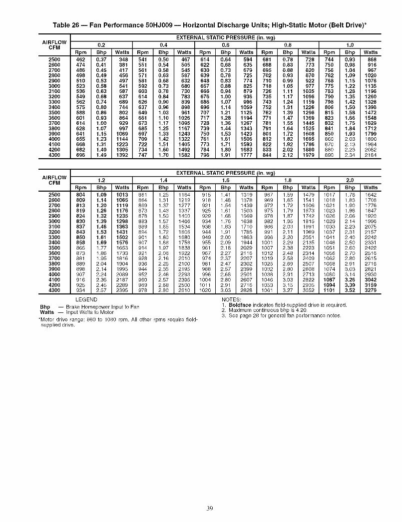
Table 26 -- Fan Performance 50HJ009 -- Horizontal Discharge Units; High-Static Motor (Belt Drive)*
AIRFLOWCFM
2500260027002800290030003100320033003400350036003700380039004000410042004300
EXTERNAL STATIC PRESSURE (in. wg)0.2 0.4 0.6 0.8 1.0
Rpm Bhp Watts Rpm Bhp Watts Rpm Bhp Watts Rpm Bhp Watts Rpm Bhp Watts462 0.37 348 541 0.50 467 614 0.64 594 681 0.78 728 744 0.93 868474 0.41 381 551 0.54 505 622 0.68 635 688 0.83 773 750 0.98 916486 0.45 417 561 0.58 545 630 0.73 679 695 0.88 820 756 1.04 967498 0.49 456 571 0.63 587 639 0.78 725 702 0.93 870 762 1.09 1020510 0.53 497 581 0.68 632 648 0.83 774 710 0.99 922 768 1.15 1076523 0.58 541 592 0.73 680 657 0.88 825 718 1.05 977 775 1.22 1135536 0.63 587 603 0.78 730 666 0.94 879 726 1.11 1035 783 1.28 1196549 0.68 637 614 0.84 783 676 1.00 936 735 1.17 1096 790 1.35 1260562 0.74 689 626 0.90 839 686 1.07 996 743 1.24 1159 798 1.42 1328575 0.80 744 637 0.96 898 696 1.14 1059 752 1.31 1226 806 1.50 1398588 0.86 802 649 1.03 961 707 1.21 1125 762 1.39 1296 815 1.58 1472601 0.93 864 661 1.10 1026 717 1.28 1194 771 1.47 1369 823 1.66 1548614 1.00 929 673 1.17 1095 728 1.36 1267 781 1.55 1445 832 1.75 1629628 1.07 997 685 1.25 1167 739 1.44 1343 791 1.64 1525 841 1.84 1712641 1.15 1069 697 1.33 1243 750 1.53 1423 801 1.72 1608 850 1.93 1799655 1.23 1144 709 1.42 1322 761 1.61 1506 812 1.82 1695 860 2.03 1890668 1.31 1223 722 1.51 1405 773 1.71 1593 822 1.92 1786 870 2.13 1984682 1.40 1305 734 1.60 1492 784 1.80 1683 833 2.02 1880 880 2.23 2082696 1.49 1392 747 1.70 1582 796 1.91 1777 844 2.12 1979 890 2.34 2184
AIRFLOWCFM
2500260027002800290030003100320033003400350036003700380039004000410042004300
Bhp -- Brake Horsepower Input to FanWatts -- Input Watts to Motor
*Motor drive range: 860 to 1080 rpm. All other rpms require field-supplied drive.
EXTERNAL STATIC PRESSURE (in. wg)1.2 1.4 1.6 1.8 2.0
Rpm Bhp Watts Rpm Bhp Watts Rpm Bhp Watts Rpm Bhp Watts Rpm Bhp Watts804 1.09 1013 861 1.25 1164 915 1.41 1319 987 1.59 1479 1017 1.78 1642809 1.14 1065 864 1.31 1219 918 1.48 1378 989 1.65 1541 1018 1.83 1708813 1.20 1119 869 1.37 1277 921 1.54 1439 972 1.72 1608 1021 1.90 1778819 1.26 1176 873 1.43 1337 925 1.81 1503 975 1.79 1673 1023 1.98 1847824 1.32 1235 878 1.50 1400 929 1.88 1569 978 1.87 1742 1026 2.06 1920830 1.39 1298 883 1.57 1466 934 1.76 1638 982 1.95 1815 1029 2.14 1996837 1.46 1363 889 1.65 1534 938 1.83 1710 986 2.03 1891 1033 2.23 2075843 1.53 1431 894 1.72 1606 944 1.91 1785 991 2.11 1969 1037 2.31 2157850 1.61 1502 901 1.80 1680 949 2.00 1863 996 2.20 2051 1041 2.40 2242858 1.69 1576 907 1.88 1758 955 2.09 1944 1001 2.29 2135 1046 2.50 2331865 1.77 1653 914 1.97 1838 981 2.18 2029 1007 2.38 2223 1051 2.60 2422873 1.88 1733 921 2.08 1922 987 2.27 2116 1012 2.48 2314 1056 2.70 2516881 1.95 1816 928 2.16 2010 974 2.37 2207 1019 2.58 2409 1062 2.80 2615889 2.04 1904 936 2.25 2100 981 2.47 2302 1025 2.69 2507 1088 2.91 2718898 2.14 1995 944 2.35 2195 988 2.57 2399 1032 2.80 2608 1074 3.03 2821907 2.24 2089 952 2.48 2293 996 2.68 2501 1038 2.91 2713 1080 3.14 2930916 2.35 2187 960 2.57 2395 1004 2.80 2607 1046 3.03 2822 1087 3.26 3042925 2.45 2289 969 2.68 2500 1011 2.91 2716 1053 3.15 2935 1094 3.39 3159934 2.57 2395 978 2.80 2610 1020 3.03 2828 1061 3.27 3052 1101 3.52 3279
LEGEND NOTES:1. Boldface indicates field-supplied drive is required.2. Maximum continuous bhp is 4.20.3. See page 28 for general fan performance notes.
39

Table 27 i Fan Performance 50HJ012 i Horizontal Discharge Units; Standard Motor (Belt Drive)*
AIRFLOWCFM
300031003200330034003500360037003800390040004100420043004400450046004700480049005000
EXTERNAL STATIC PRESSURE (in. wg)0.2 0.4 0.6 0.8 1.0
Rpm Bhp Watts Rpm Bhp Watts Rpm Bhp Watts Rpm Bhp Watts Rpm Bhp Watts523 0.58 541 592 0.73 680 657 0.88 825 718 1.05 977 775 1.22 1135536 0.63 587 603 0.78 730 666 0.94 879 726 1.11 1035 783 1.28 1196549 0.68 637 614 0.84 783 676 1.00 936 735 1.17 1096 790 1.35 1260562 0.74 689 626 0.90 839 686 1.07 996 743 1.24 1159 798 1.42 1328575 0.80 744 637 0.96 898 696 1.14 1059 752 1.31 1226 806 1.50 1398588 0.86 802 649 1.03 961 707 1.21 1125 762 1.39 1296 815 1.58 1472601 0.93 864 661 1.10 1026 717 1.28 1194 771 1.47 1369 823 1.66 1548614 1.00 929 673 1.17 1095 728 1.36 1267 781 1.55 1445 832 1.75 1629628 1.07 997 685 1.25 1167 739 1.44 1343 791 1.64 1525 841 1.84 1712641 1.15 1069 697 1.33 1243 750 1.53 1423 801 1.72 1608 850 1.93 1799655 1.23 1144 709 1.42 1322 761 1.61 1506 812 1.82 1695 860 2.03 1890668 1.31 1223 722 1.51 1405 773 1.71 1593 822 1.92 1786 870 2.13 1984682 1.40 1305 734 1.60 1492 784 1.80 1683 833 2.02 1880 880 2.23 2082696 1.49 1392 747 1.70 1582 796 1.91 1777 844 2.12 1979 890 2.34 2184710 1.59 1482 760 1.80 1677 808 2.01 1876 855 2.23 2081 900 2.46 2290723 1.69 1577 773 1.90 1775 820 2.12 1978 866 2.35 2187 910 2.57 2400737 1.80 1675 785 2.01 1877 832 2.24 2085 877 2.46 2297 921 2.70 2514751 1.91 1778 798 2.13 1984 844 2.35 2195 889 2.59 2412 932 2.82 2633765 2.02 1885 812 2.25 2095 856 2.48 2310 900 2.71 2531 942 2.95 2756779 2.14 1996 825 2.37 2210 869 2.61 2430 912 2.85 2654 953 3.09 2883793 2.26 2112 838 2.50 2330 881 2.74 2554 923 2.98 2782 965 3.23 3014
AIRFLOWCFM
300031003200330034003500360037003800390040004100420043004400450046004700480049005000
Bhp -- Brake Horsepower Input to FanWatts -- Input Watts to Motor
*Motor drive range: 860 to 1080 rpm. All other rpms require field-supplied drive.
EXTERNAL STATIC PRESSURE (in. wg)1.2 1.4 1.6 1.8 2.0
Rpm Bhp Watts Rpm Bhp Watts Rpm Bhp Watts Rpm Bhp Watts Rpm Bhp Watts830 1.39 1298 883 1.57 1466 934 1.76 1638 982 1.95 1815 1029 2.14 1996837 1.46 1363 889 1.65 1534 938 1.83 1710 986 2.03 1891 1033 2.23 2075843 1.53 1431 894 1.72 1606 944 1.91 1785 991 2.11 1969 1037 2.31 2157850 1.61 1502 901 1.80 1680 949 2.00 1863 996 2.20 2051 1041 2.40 2242858 1.69 1576 907 1.88 1758 955 2.09 1944 1001 2.29 2135 1046 2.50 2331865 1.77 1653 914 1.97 1838 961 2.18 2029 1007 2.38 2223 1051 2.60 2422873 1.86 1733 921 2.06 1922 967 2.27 2116 1012 2.48 2314 1056 2.70 2516881 1.95 1816 928 2.16 2010 974 2.37 2207 1019 2.58 2409 1062 2.80 2615889 2.04 1904 936 2.25 2100 981 2.47 2302 1025 2.69 2507 1068 2.91 2716898 2.14 1995 944 2.35 2195 988 2.57 2399 1032 2.80 2608 1074 3.03 2821907 2.24 2089 952 2.46 2293 996 2.68 2501 1038 2.91 2713 1080 3.14 2930916 2.35 2187 960 2.57 2395 1004 2.80 2607 1046 3.03 2822 1087 3.26 3042925 2.45 2289 969 2.68 2500 1011 2.91 2716 1053 3.15 2935 1094 3.39 3159934 2.57 2395 978 2.80 2610 1020 3.03 2828 1061 3.27 3052 1101 3.52 3279944 2.69 2504 986 2.92 2723 1028 3.16 2946 1068 3.40 3173 1108 3.65 3403954 2.81 2618 996 3.05 2840 1037 3.29 3067 1076 3.54 3297 -- -- --963 2.93 2736 1005 3.18 2962 1045 3.42 3192 1085 3.67 3426 -- -- --974 3.07 2858 1014 3.31 3088 1054 3.56 3322 ......984 3.20 2985 1024 3.45 3219 .........994 3.34 3116 1034 3.60 3353 .........
1005 3.49 3251 ............
LEGEND NOTES:1. Boldface indicates field-supplied drive is required.2. Maximum continuous bhp is 3.70.3. See page 28 for general fan performance notes.
4O

Table 28 -- Fan Performance 50HJ012 -- Horizontal Discharge Units; High-Static Motor (Belt Drive)*
AIRFLOWCFM
3O0031003200330034003500360037003800390040004100420043004400450046004700480049005000
EXTERNAL STATIC PRESSURE (in. wg)0.2 0.4 0.6 0.8 1.0
Rpm Bhp Watts Rpm Bhp Watts Rpm Bhp Watts Rpm Bhp Watts Rpm Bhp Watts523 0.58 541 592 0.73 680 657 0.88 825 718 1.05 977 775 1.22 1135536 0.63 587 603 0.78 730 666 0.94 879 726 1.11 1035 783 1.28 1196549 0.68 637 614 0.84 783 676 1.00 936 735 1.17 1096 790 1.35 1260562 0.74 689 626 0.90 839 686 1.07 996 743 1.24 1159 798 1.42 1328575 0.80 744 637 0.96 898 696 1.14 1059 752 1.31 1226 806 1.50 1398588 0.86 802 649 1.03 961 707 1.21 1125 762 1.39 1296 815 1.58 1472601 0.93 864 661 1.10 1026 717 1.28 1194 771 1.47 1369 823 1.66 1548614 1.00 929 673 1.17 1095 728 1.36 1267 781 1.55 1445 832 1.75 1629628 1.07 997 685 1.25 1167 739 1.44 1343 791 1.64 1525 841 1.84 1712641 1.15 1069 697 1.33 1243 750 1.53 1423 801 1.72 1608 850 1.93 1799655 1.23 1144 709 1.42 1322 761 1.61 1506 812 1.82 1695 860 2.03 1890668 1.31 1223 722 1.51 1405 773 1.71 1593 822 1.92 1786 870 2.13 1984682 1.40 1305 734 1.60 1492 784 1.80 1683 833 2.02 1880 880 2.23 2082696 1.49 1392 747 1.70 1582 796 1.91 1777 844 2.12 1979 890 2.34 2184710 1.59 1482 760 1.80 1677 808 2.01 1876 855 2.23 2081 900 2.46 2290723 1.69 1577 773 1.90 1775 820 2.12 1978 866 2.35 2187 910 2.57 2400737 1.80 1675 785 2.01 1877 832 2.24 2085 877 2.46 2297 921 2.70 2514751 1.91 1778 798 2.13 1984 844 2.35 2195 889 2.59 2412 932 2.82 2633765 2.02 1885 812 2.25 2095 856 2.48 2310 900 2.71 2531 942 2.95 2756779 2.14 1996 825 2.37 2210 869 2.61 2430 912 2.85 2654 953 3.09 2883793 2.26 2112 838 2.50 2330 881 2.74 2554 923 2.98 2782 965 3.23 3014
AIRFLOWCFM
3O0031003200330034003500360037003800390040004100420043004400450046004700480049005000
Bhp -- Brake Horsepower Input to FanWatts -- Input Watts to Motor
*Motor drive range: 830 to 1130 rpm. All other rpms require field-supplied drive.
EXTERNAL STATIC PRESSURE (in. wg)
1.2 1.4 1.6 1.8 2.0
Rpm Bhp Watts Rpm Bhp Watts Rpm Bhp Watts Rpm Bhp Watts Rpm Bhp Watts
830 1.39 1298 883 1.57 1466 934 1.76 1638 982 1.95 1815 1029 2.14 1996837 1.46 1363 889 1.65 1534 938 1.83 1710 986 2.03 1891 1033 2.23 2075843 1.53 1431 894 1.72 1606 944 1.91 1785 991 2.11 1969 1037 2.31 2157850 1.61 1502 901 1.80 1680 949 2.00 1863 996 2.20 2051 1041 2.40 2242858 1.69 1576 907 1.88 1758 955 2.09 1944 1001 2.29 2135 1046 2.50 2331865 1.77 1653 914 1.97 1838 961 2.18 2029 1007 2.38 2223 1051 2.60 2422873 1.86 1733 921 2.06 1922 967 2.27 2116 1012 2.48 2314 1056 2.70 2516881 1.95 1816 928 2.16 2010 974 2.37 2207 1019 2.58 2409 1062 2.80 2615889 2.04 1904 936 2.25 2100 981 2.47 2302 1025 2.69 2507 1068 2.91 2716898 2.14 1995 944 2.35 2195 988 2.57 2399 1032 2.80 2608 1074 3.03 2821907 2.24 2089 952 2.46 2293 996 2.68 2501 1038 2.91 2713 1080 3.14 2930916 2.35 2187 960 2.57 2395 1004 2.80 2607 1046 3.03 2822 1087 3.26 3042925 2.45 2289 969 2.68 2500 1011 2.91 2716 1053 3.15 2935 1094 3.39 3159934 2.57 2395 978 2.80 2610 1020 3.03 2828 1061 3.27 3052 1101 3.52 3279944 2.69 2504 986 2.92 2723 1028 3.16 2946 1068 3.40 3173 1108 3.65 3403954 2.81 2618 996 3.05 2840 1037 3.29 3067 1076 3.54 3297 1115 3.79 3531963 2.93 2736 1005 3.18 2962 1045 3.42 3192 1085 3.67 3426 1123 3.93 3664974 3.07 2858 1014 3.31 3088 1054 3.56 3322 1093 3.82 3560 1131 4.08 3801984 3.20 2985 1024 3.45 3219 1063 3.71 3456 1102 3.96 3697 1139 4.23 3943994 3.34 3116 1034 3.60 3353 1073 3.85 3594 1111 4.12 3839 1148 4.38 4088
1005 3.49 3251 1044 3.74 3492 1082 4.01 3737 1119 4.27 3986 1156 4.55 4238
LEGEND NOTES:
1. Boldface indicates field-supplied drive is required.2. Maximum continuous bhp is 5.25.3. See page 28 for general fan performance notes.
4!

Table 29 -- Fan Performance 50HJ014 -- Horizontal Discharge Units; Standard Motor (Belt Drive)*
AIRFLOWCFM
370038003900400041004200430044004500460047004800490050005100520053005400550056005700580059006000610062006300
EXTERNAL STATIC PRESSURE (in. wg)0.2 0.4 0.6 0.8 1.0
Rpm Bhp Watts Rpm Bhp Watts Rpm Bhp Watts Rpm Bhp Watts Rpm Bhp Watts614 1.00 929 673 1.17 1095 728 1.36 1267 781 1.55 1445 832 1.75 1629628 1.07 997 685 1.25 1167 739 1.44 1343 791 1.64 1525 841 1.84 1712641 1.15 1069 697 1.33 1243 750 1.53 1423 801 1.72 1608 850 1.93 1799655 1.23 1144 709 1.42 1322 761 1.61 1506 812 1.82 1695 860 2.03 1890668 1.31 1223 722 1.51 1405 773 1.71 1593 822 1.92 1786 870 2.13 1984682 1.40 1305 734 1.60 1492 784 1.80 1683 833 2.02 1880 880 2.23 2082696 1.49 1392 747 1.70 1582 796 1.91 1777 844 2.12 1979 890 2.34 2184710 1.59 1482 760 1.80 1677 808 2.01 1876 855 2.23 2081 900 2.46 2290723 1.69 1577 773 1.90 1775 820 2.12 1978 866 2.35 2187 910 2.57 2400737 1.80 1675 785 2.01 1877 832 2.24 2085 677 2.46 2297 921 2.70 2514751 1.91 1778 798 2.13 1984 844 2.35 2195 889 2.59 2412 932 2.82 2633765 2.02 1885 812 2.25 2095 856 2.48 2310 900 2.71 2531 942 2.95 2756779 2.14 1996 825 2.37 2210 869 2.61 2430 912 2.85 2654 953 3.09 2883793 2.26 2112 838 2.50 2330 881 2.74 2554 923 2.98 2782 965 3.23 3014807 2.39 2232 851 2.63 2455 894 2.88 2682 935 3.13 2914 976 3.38 3150821 2.53 2357 864 2.77 2584 906 3.02 2815 947 3.27 3050 987 3.53 3292835 2.67 2487 878 2.91 2718 919 3.17 2953 959 3.42 3193 999 3.69 3437850 2.81 2622 891 3.06 2856 932 3.32 3096 971 3.58 3339 1010 3.85 3588864 2.96 2762 905 3.22 3000 945 3.48 3242 984 3.74 3491 1022 4.01 3743878 3.12 2906 918 3.38 3148 958 3.64 3396 996 3.91 3648 1034 4.19 3903892 3.28 3055 932 3.54 3302 971 3.81 3554 1008 4.09 3810 1045 4.36 4069907 3.44 3211 945 3.71 3461 984 3.99 3716 1021 4.26 3976 1057 4.55 4240921 3.61 3370 959 3.89 3626 997 4.17 3885 1033 4.45 4149 1069 4.74 4416935 3.79 3536 973 4.07 3795 1010 4.35 4059 1046 4.64 4326 1082 4.93 4598949 3.98 3707 987 4.26 3970 1023 4.54 4238 1059 4.84 4510 1094 5.13 4785964 4.16 3883 1000 4.45 4151 1036 4.74 4422 1071 5.04 4698 -- -- --978 4.36 4066 1014 4.65 4337 1050 4.95 4613 1084 5.25 4892 -- -- --
AIRFLOWCFM
37OO38003900400041004200430044004500460047004800490050005100520053005400550056005700580059006000610062006300
EXTERNAL STATIC PRESSURE (in. wg)1.2 1.4 1.6 1.8 2.0
Rpm Bhp Watts Rpm Bhp Watts Rpm Bhp Watts Rpm Bhp Watts Rpm Bhp Watts881 1.95 1816 928 2.16 2010 974 2.37 2207 1019 2.58 2409 1062 2.80 2615889 2.04 1904 936 2.25 2100 981 2.47 2302 1025 2.69 2507 1068 2.91 2716898 2.14 1995 944 2.35 2195 988 2.57 2399 1032 2.80 2608 1074 3.03 2821907 2.24 2089 952 2.46 2293 996 2.68 2501 1038 2.91 2713 1080 3.14 2930916 2.35 2187 960 2.57 2395 1004 2.80 2607 1046 3.03 2822 1087 3.26 3042925 2.45 2289 969 2.68 2500 1011 2.91 2716 1053 3.15 2935 1094 3.39 3159934 2.57 2395 978 2.80 2610 1020 3.03 2828 1061 3.27 3052 1101 3.52 3279944 2.69 2504 986 2.92 2723 1028 3.16 2946 1068 3.40 3173 1108 3.65 3403954 2.81 2618 996 3.05 2840 1037 3.29 3067 1076 3.54 3297 1115 3.79 3531963 2.93 2736 1005 3.18 2962 1045 3.42 3192 1085 3.67 3426 1123 3.93 3664974 3.07 2858 1014 3.31 3088 1054 3.56 3322 1093 3.82 3560 1131 4.08 3801984 3.20 2985 1024 3.45 3219 1063 3.71 3456 1102 3.96 3697 1139 4.23 3943994 3.34 3116 1034 3.60 3353 1073 3.85 3594 1111 4.12 3839 1148 4.38 4088
1005 3.49 3251 1044 3.74 3492 1082 4.01 3737 1119 4.27 3986 1156 4.55 42381015 3.64 3391 1054 3.90 3636 1092 4.17 3885 1129 4.44 4137 1165 4.71 43931026 3.79 3536 1064 4.06 3784 1101 4.33 4037 1138 4.60 4293 1174 4.88 45531037 3.95 3685 1075 4.22 3938 1111 4.50 4194 1147 4.78 4454 1183 5.06 47181048 4.12 3840 1085 4.39 4096 1121 4.67 4356 1157 4.95 4619 1192 5.24 48861059 4.29 3999 1096 4.57 4259 1132 4.85 4523 1167 5.14 4790 -- -- --1070 4.46 4163 1106 4.75 4427 1142 5.03 4695 ......1082 4.65 4333 1117 4.93 4601 1152 5.22 4872 ......1093 4.83 4508 1128 5.13 4779 .........1105 5.03 4688 ............1116 5.23 4873 ............
LEGEND
Bhp -- Brake Horsepower Input to FanWatts -- Input Watts to Motor
*Motor drive range: 830 to 1130 rpm. All other rpms require field-supplied drive.
NOTES:1. Boldface indicates field-supplied drive is required.2. Maximum continuous bhp is 5.25.3. See page 28 for general fan performance notes.
42

PRE-START-UP NOTE: Ensure wiling does not contact any refiigerant tubing.
Failure to observe the following warnings could result inserious pel_onal injuu:
1. Follow recognized safety practices and wear protec-tive goggles when checking or servicing refi'igerantsystem.
2. Do not operate compressor or provide any electricpower to unit unless compressor terminal cover is inplace and secured.
3. Do not remove complessor terminal cover until allelectrical sources ale disconnected and properlytagged.
4. Relieve all plessure from system before touching ordisturbing anything inside terminal box if refiigerantleak is suspected around complessor terminals. Useaccepted methods to recover refiigemnt.
5. Never attempt to repair soldered connection while re-fiigemnt system is under pressme.
6. Do not use torch to remove any component. Systemcontains oil and refrigerant under pressure. To lemovea component, wear protective goggles and proceed asfollows:
a. Shut off electrical power to unit and installlockout tag.
b. Relieve all pressure from system using bothhigh and low-pressure ports. Use acceptedmethods to recover refrigerant.
c. Cut component connection tubing with tubingcutter and remove component from unit.
d. Carefully unsweat remaining tubing stubswhen necessary. Oil can ignite when exposed totorch flame.
Proceed as follows to inspect and prepare the unit for initkflstart-up:
1. Remove _dl access panels.2. Read and follow instructions on all WARNING. CAU-
TION, and INFORMATION labels attached to orshipped with unit.
3. Make the following inspections:
a. Inspect for shipping and handling damages such asbroken lines, loose parts, or disconnected wires.
b. Inspect for oil at all refiigerant tubing connectionsand on unit base. Detecting oil generally indicatesa refrigerant leak. Leak-test all refrigerant tubingconnections using electronic leak detector, halidetorch, or liquid-soap solution.
c. Inspect all field-wiring and factou-wiring connec-tions. Be sure that connections are completed andtight.
d. Inspect coil fins. If damaged during shipping andhandling, carefully straighten fins with a fin comb.
4. Verify the following:
a. Make sure that condenser-fan blades are correctlypositioned in fan orifice. Refer to Condenser-FanAdjustment section on page 48 for more details.
b. Make sure that air filters are in place.
c. Make sure that condensate drain trap is filled withwater to ensure proper drainage.
d. Make sure that all tools and miscellaneous loose
parts have been removed.
e. Make sure that the start-up checklist has been per-formed and filled out.
START-UP
Unit Preparation- Make sure that unit has been in-stalled in accordance with these inst_dlafion instructions and
applicable codes.
Return-Air Filters- Make sure conect filters are in-
stalled in unit (see Table 1). Do not operate unit without return-_6r filters.
Outdoor-Air Inlet Screens -- Outdoor-air inlet screensmust be in place before operating unit.
Compressor Mounting -- Compressorsme internallyspring mounted. Do not loosen or remove compressor hold-down bolts.
Internal Wiring- Check all electrical connections inunit control boxes; tighten as required.
Refrigerant Service Ports-- Each refrigerant sys-tem has 4 Schmder-type service gage ports: one on the suctionline, one on the liquid line, and 2 on the compressor dischtugeline. Be sure that caps on the ports are tight.
High Flow Valves- Two high flow refiigerant valves;ue located on the compressor hot gas and suction tubes. L;ugeblack plastic caps distinguish these valves with o-rings locatedinside the caps. These valves can not be accessed for service inthe field. Ensure the plastic caps are in place and tight or thepossibility of refrigerant leakage could occm:
Compressor Rotation -- On 3-phaseunits, it is impor-tant to be certain the scroll compressor is rotating in the properdirection. To determine whether or not compressor is rotatingin the proper direction:
1. Connect service gages to suction and disch_uge plessurefittings.
2. Energize the compressoc
3. The suction pressure should drop and the disch;uge pres-sure should rise, as is normal on any st;u't-up.
If the suction pressure does not diop and the discharge pres-sure does not rise to normal levels:
1. Note that the evaporator fan is probably also rotating inthe wrong direction.
2. Turn off power to the unit and install lockout tag.
3. Reverse any two of the unit power leads.
4. Turn on power to the unit.
The suction and discharge pressure levels should now moveto their norm_d start-up levels.
NOTE: When the compressor is rotating in the wrong dilec-tion, the unit makes an elevated level of noise and does notprovide heating or cooling.
Compressor damage will occur if rotation is not immedi-ately corrected.
Cooling -- To start unit, turn on main power supply. Setsystem selector switch at COOL position and fan switch atAUTO position. Adjust thermostat to a setting below roomtemperature. Compressor starts on closure of contactol:
Check unit charge. Refer to Refiigerant Charge section onpage 48.
Reset thermostat at a position above room temperature.Compressor will shut off.
43

TOSHUTOFFUNIT-- SetsystemselectorswitchatOFFposition.Resettingthermostatatapositionaboveroomtem-peratureshutsunitofftemporarilyuntilspacetemperatureex-ceedsthermostatsetting.Units_ueequippedwithCycle-LOCTM protection device. Unit shuts down on any safety tripand remains off; an indicator light on the thermostat comes on.Check reason for safety trip.
Compressor restart is accomplished by manual reset at thethermostat by turning the selector switch to OFF position andthen ON position.
Heating (If Accessory Heater is Installed) -- Tost;ut unit, turn on main power supply.
Set thermostat at HEAT position and a setting above roomtemperature, and set fan at AUTO position.
First stage of thermostat energizes the fi_st-stage electricheater elements; second stage energizes second-stage electricheater elements. Check heating effects at air supply grille(s).
If accessory electric heaters do not energize, reset limitswitch (located on evaporator-fan scroll) by pressing button lo-cated between terminals on the switch.
TO SHUT OFF UNIT -- Set system selector switch at OFFposition. Resetting heating selector lever below room tempera-ture temporarily shuts unit off until space temperature f;dls be-low thermostat setting.
Safety Relief- A soil solder joint in the suction lineat the loss-of-charge/low-pressme switch fitting providesplessure relief under abnormal temperature and pressureconditions.
Ventilation (Continuous Fan) -- Set fan and systemselector switches at ON and OFF positions, respectively.Evaporator fan operates continuously to provide constant aircirculation.
Operating SequenceCOOLING. UNITS WITHOUT ECONOMIZER -- Whenthe thermostat calls for cooling, terminals G and YI zue ener-gized. The indoor (evaporator) fan contactor (IFC) and com-pressor contactor no. 1 (CI) _ue energized and the evaporator-fan motor, compressor no. 1, and condenser fans start. The con-denser-fan motors run continuously while unit is in cooling. Ifthe thermostat calls for a second stage of cooling by energizingY2, compressor contactor no. 2 (C2) is energized and compres-sor no. 2 starts.
HEATING. UNITS WITHOUT ECONOMIZER (If Acces-sory Heater is Installed) -- Upon a call for heating throughterminal WI, IFC and heater contactor no. 1 (HCI) are ener-gized. On units equipped for 2 stages of heat, when additionalheat is needed, HC2 is energized through W2.COOLING UNITS WITH ECONOMISER IV -- When free
cooling is not available, the compressors will be controlled bythe zone thermostat. When free cooling is available, theoutdoor-air &unper is modulated by the EconoMiSer IV con-trol to provide a 50 to 55 F supply-air temperature into thezone. As the supply-air temperature fluctuates above 55 orbelow 50 E the dampers will be modulated (open or close) tobring the supply-air temperature back within the set pointlimits.
For EconoMi$er IV operation, there must be a thermostatc_dl for the fan (G). This will move the damper to its minimumposition during the occupied mode.
Above 50 F supply-air temperature, the &tmpers will modu-htte from 100% open to the minimum open position. From 50 Fto 45 F supply-air temperature, the &Lmpers will maintain atthe minimum open position. Below 45 F the dampers will becompletely shut. As the supply-air temperature rises, the damp-ers will come back open to the minimum open position oncethe supply air temperature rises to 48 E
If optional power exhaust is installed, as the outdoor-airdamper opens and closes, the power exhaust fans will be ener-gized and deenergized.
If field-installed accessory CO2 sensors are connected to theEconoMi$er IV control, a demand controlled ventilation strate-
gy will begin to operate. As the CO2 level in the zone increasesabove the CO2 set point, the minimum position of the damperwill be increased proportionally. As the CO2 level decreasesbecause of the inclease in fresh air. the outdoor-air damper willbe proportionally closed. Damper position will follow the high-er demand condition fiom DCV mode or free cooling mode.
Damper movement from full closed to full open (or vicevel_a) will take between 11/2and 21/2 minutes.
If fiee cooling can be used as determined from the appropri-ate changeover command (switch, dq bulb, enthalpy curve,differential &y bulb, or differential enthalpy), a call for cooling(YI closes at the thermostat) will cause the control to modulatethe &tmpel_ open to maintain the supply air temperatme setpoint at 50 to 55 E
As the supply-air temperature drops below the set pointrange of 50 to 55 E the control will modulate the outdoor-airdampel_ closed to maintain the proper supply-air temperature.
HEATING, UNITS WITH ECONOMI$ER IV -- When theroom temperature calls for heat, the heating controls are ener-gized as described in the Heating, Units Without Economizersection. When the thermostat is satisfied, the economizerdamper moves to the minimum position.
COOLING, UNITS WITH ECONOMI$ER2, PREMIER-LINK TM CONTROL AND A THERMOSTAT -- When free
cooling is not avaihtble, the compressols will be controlled bythe PremierLink control in response to the YI and Y2 inputsfrom the thermostat.
The PremierLink control will use the following informationto determine if free cooling is available:
• Indoor fan has been on for at least 30 seconds.
• The SPT, SAT. and OAT inputs must have valid readings.• OAT must be less than 75 F.• OAT must be less than SPT.• Enthalpy must be LOW (may be jumpered if an enthalpy
sensor not available).• Economizer position is NOT forced.
Pre-cooling occurs when thele is no call from the therlnostatexcept G Pre-cooling is defined as the economizer modulatesto provide 70 F supply ail:
When free cooling is available the PremierLink control willcontrol the compressors and economizer to provide a supply-air temperature determined to meet the YI and Y2 calls fromthe thermostat using the following three routines. The threecontrol routines are based on OAT.
The 3 routines tue based on OAT where:
SASP = Supply Air Set Point
DXCTLO = Dilect Expansion Cooling Lockout Set PointP1D = Proportional Integral
Routine 1 (OAT < DXCTLO)• YI energized - economizer maintains a SASP =
(SATLOI + 3).• Y2 energized - economizer maintains a SASP =
(SATLO2 + 3).
Routine 2 (DXCTLO < OAT < 68 F)
• If only YI energized, the economizer maintains a SASP= (SATLOI + 3).
• If SAT > SASP + 5 and economizer position > 80%,economizer will go to minimum position for 3 minutes oruntil SAT > 68 IF.
• First stage of mechanical cooling will be energized.• Integrator resets.
44

• EconomizeropensagainandcontrolstocunentSASPafterstageoneonfor90seconds.
• WithYI andY2 energizedEconomizermaintainsanSASP=SATLO2+3.
• If SAT> SASP+ 5 andeconomizerposition>80%,economizerwill gotominimumpositionfor3minutesoruntilSAT>68IF.
• If compressoroneisonthensecondstageofmechanicalcoolingwill beenergized.Otherwisethefirststagewillbeenelgized.
• Integratorresets.• Economizeropensagainandcontrolsto SASPafter
stageoneonfor90seconds.Routine3(OAT>68)
• Economizerisopened100%.• Compressors 1 and 2 are cycled based on YI and Y2
using minimum on and off times and watching the sup-ply air temperature as compared to SATLOI andSATLO2 set points.
If optional power exhaust is inst¢flled, as the outdoor-airdamper opens and closes, the power exhaust fans will be ener-gized and deenergized.
If field-installed accessory CO2 sensors are connected to thePremierLink TM control, a P1D-controlled demand ventilationstrategy will begin to operate. As the CO2 level in file zoneincreases above the CO2 set point, the minimum position of thedamper will be increased proportionally. As the CO2 leveldecreases because of the increase in fresh air, the outdoor-airdamper will be proportionally closed.
HEATING. UNITS WITH ECONOMISER2, PREMIERLINKCONTROL AND A THERMOSTAT -- When the thermostat
cMls for heating, terminal WI is energized. The PremierLinkcontrol will move the economizer damper to the minimumposition if there is a call for G and closed if fllere is a call forWl without G The IFC and heater contactor no. 1 (HCI) areenergized.
On units equipped for two stages of heat, when additionalheat is needed, W2 is energized and the electric heatel_ providethe additional heat. When the thermostat is satisfied and WI is
deenergized, the IFM stops after a 45-second time-off delayunless G is still maintained.
COOLING. UNITS WITH ECONOMI$ER2, PREMIER-LINK CONTROL AND A ROOM SENSOR -- When freecooling is not available, the compressolx will be controlled bythe PremierLink controller using a PID Enor reduction calcula-tion as indicated by Fig. 47.
The PremierLink controller will use the following informa-tion to determine if fiee cooling is available:
• Indoor fan has been on for at least 30 seconds.• The SPT. SAT. and OAT inputs must have valid readings.• OAT must be less than 75 F.• OAT must be less than SPY'.
• Enthalpy must be LOW (may be jumpered if andenthalpy sensor is not available).
• Economizer position is NOT forced.
When free cooling is available, the outdoor-air dmnper ispositioned through the use of a Proportional Integral (PID)control process to provide a calculated supply-air temperatureinto the zone. The supply air will maintain the space tempera-ture between the heating and cooling set points as indicated inFig. 48.
The PremierLink control will integrate the compressorsstages with the economizer based on similar logic as the threeroutines listed in the previous section. The SASP will float upand down based on the error reduction calculations that com-
pine space temperature and space set point.
When outdoor-air temperature conditions require the econo-mizer to close for a compressor stage-up sequence, the
economizer control integrator is reset to zero after the stage-upsequence is completed. This prevents the supply-air tempera-ture from diopping too quickly and creating a freeze conditionthat would make the compressor turn off prematmely.
The high space set point is used for DX (direct expansion)cooling control, while the economizer space set point is acalculated v_due between the heating and cooling set points.The economizer set point will always be at least one degreebelow the cooling set point, allowing for a smooth transitionfrom mechanical cooling with economizer assist, back toeconomizer cooling as the cooling set point is achieved.The compressors may be used for initial cooling then thePremierLink controller will modulate the economizer using anerror reduction calculation to hold the space temperaturebetween the heating and cooling set points. See Fig. 48.
The controller uses the following conditions to determineeconomizer cooling:
• Enthalpy is Low• SAT reading is available• OAT reading is available• SPT reading is available• OAT < SPT• Economizer Position is NOT forced
If any of the above conditions are not met, the economizersubmaster reference (ECSR) is set to maximum limit and the&tmper moves to minimum position. The operating sequenceis complete. The ECSR is recalculated every 30 seconds.
If an optional power exhaust is installed, as the outdoor-air&tmper opens and closes, the power exhaust fans will beenergized and deenergized.
ku 757
_: 734££
724-
714
Lu 704on< 694
o) 68 J
TEMPERATURECONTROL
TIME
...... SET POINT
_TEMPERATURE
NOTE: PremierLink control performs smart staging of 2 stages of DXcooling and up to 3 stages of heat.
Fig. 47 -- DX Cooling TemperatureControl Example
LU
LUo
09
TEMPERATURE CONTROL
75,
74t 73
72 ......... _ .......................................... COOL SETPOINTI
\ / --TEMPERATUREI704 ........ _ ............................. HEAT SETPOINT ]
694
68 iTIME
Fig. 48 -- Economizer TemperatureControl Example
45

If field-installed accessory CO2 sensors ale connected tothe PremierLink TM control, a PID-controlled demand ventila-tion strategy will begin to operate. As the CO2 level in the zoneincreases above the CO2 set point, the minimum position of thedmnper will be increased proportionally. As the CO2 leveldecreases because of the increase in fiesh all: the outdoor-airdmnper will be proportionally closed.
HEATING. UNIT WITH ECONOMISER2, PREM[ERLINKCONTROL AND A ROOM SENSOR -- Every 40 secondsthe controller will calculate the required heat stages (maximumof 3) to maintain supply-air temperature (SAT) if the followingqualifying conditions are met:
• Indoor fan has been on for at least 30 seconds.• COOL mode is not active.• OCCUPIED, TEMR COMPENSATED START or
HEAT mode is active.
• SAT reading is available.• Fire shutdown mode is not active.
If all of the above conditions are met, the number of heatstages is calculated; otherwise the required number of heatstages will be set to 0.
If the PremierLink controller determines that heat stages tuerequired, the economizer damper will be moved to minimumposition if occupied and closed if unoccupied.
Staging should be as follows:
If Heating PID STAGES=2
• HEAT STAGES=I (50% capacity) will energize HSI• HEAT STAGES=2 (100% capacity) will energize HS2
If Heating PID STAGES=3 and AUXOUT = HS3
• HEAT STAGES=I (33% capacity) will energize HSI• HEAT STAGES=2 (66% capacity) will energize HS2• HEAT STAGES=3 (100% capacity) will energize HS3
UNITS WITH HUMIDI-MIZER TM ADAPTIVE DEHU-MIDIFICATION SYSTEM
Normal Design Cooling Operation -- When the rooftop op-erates under the normal sequence of operation, the compressol_will cycle to maintain indoor conditions. See Fig. 49.
The Humidi-MiZer adaptive dehumidification system in-cludes a factory-installed MotormastelN) low ambient controlto keep the head and suction pressure high, allowing norm_fldesign cooling mode operation down to 0° IF.
Subcooling Mode -- When subcooling mode is initiated, thiswill energize (close) the liquid line solenoid valve (LLSV)forcing the hot liquid refrigerant to enter into the subcoolingcoil (see Fig. 50).
As the hot liquid refrigerant passes through the subcoolinJreheat dehumidification coil, it is exposed to the cold supplyairflow coming fllrough the evaporator coil. The liquid is fur-ther subcooled to a temperature approaching the evaporatorleaving-air temperature. The liquid then entel_ a thermostaticexpansion valve (TXV) where the liquid drops to a lowerpressure. The TXV does not have a plessure drop great enoughto change the liquid to a 2-phase fluid, so the liquid then entersthe Acutrol TM device at the evaporator coil.
The liquid enters the evaporator coil at a temperature lowerthan in standm'd cooling operation. This lower temperatme in-creases the latent capacity of the rooftop unit. The refrigerantpasses through the evaporator and is turned into a vapor. Theair passing over the evaporator coil will become colder thanduring normal operation. Howevel: as this same air passes overthe subcooling coil, it will be slightly warmed, p_utially leheat-ing the all:
Subcooling mode operates only when the outside-air tem-peratme is w_umer than 40 E A factory-installed temperatureswitch located in the condenser section will lock out subcool-
ing mode when the outside temperature is cooler than 40 E
LPS /
Fig. 49 -- Humidi-MiZer Normal DesignCooling Operation
/
LPS
Fig. 50 -- Humidi-MiZer Subcooling ModeOperation
The scroll compmssol_ are eqm pped with crankcase heatersto provide protection for the compressors due to the additiomflrefrigerant charge required by the subcooling/reheat coil.
When in subcooling mode, there is a slight decrease in sys-tem total gross capacity (5% less), a lower gross sensiblecapacity (20% less), and a greatly increased latent capacity (upto 40% more).
Hot Gas Reheat Mode -- When the humidity levels in thespace lequire humidity control, a hot gas solenoid wdve (spe-cific to hot gas reheat mode only) will open to bypass a portionof hot gas refrigerant around file condenser coil (see Fig. 51 ).
This hot gas will mix with liquid refrigerant leaving the con-denser coil and flow to the subcoolingheheat dehumidificationcoil. Now the conditioned air coming off the evaporator will becooled and dehumidified, but will be warmed to neutral condi-tions (72 F to 75 F) by the subcooling/reheat dehumidificationcoil.
NOTE: The 50HJ008-014 rooftop units can operate one circuitin subcooling mode and one circuit in hot gas reheat mode orboth circuits in hot gas reheat mode, or both in norm_d designcooling mode.
46
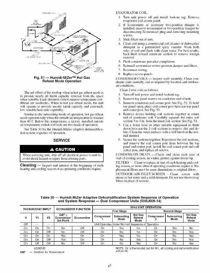
-/\ crosse
VALVE / tSV
Fig. 51 -- Humidi-MiZer TM Hot GasReheat Mode Operation
The net effect of the rooftop when in hot gas reheat mode is
to provide nearly _dl latent capacity removal from the spacewhen sensible loads diminish (when outdoor temperature con-
ditions are moderate). When in hot gas reheat mode, the unit
will operate to provide mostly latent capacity and extremelylow sensible heat ratio capability.
Similm" to the subcooling mode of operation, hot gas reheat
mode operates only when file outside air temperature is warmer
than 40 E Below this temperature, a factory installed outside
air temperature switch will lock out this mode of operation.
See Table 30 for the Humidi-MiZer adaptive dehumidifica-
tion system sequence of operation.
SERVICE
When servicing unit, shut off all electfic:d power to unit toavoid shock hazard or injury from rotating parts.
Cleaning --Inspect unit interior at the beginning of eachheating and cooling season or as operating conditions require.
EVAPORATOR COIL
1. Turn unit power off and install lockout tag. Removeew_porator coil access panel.
2. If Economizer or accessory two-position dalnper isinstalled, remove economizer or two-position dalnper bydisconnecting Economizer plug and removing mountingscrews.
3. Slide filters out of unit.
4. Clean coil using a commercial coil cleaner or dishwasherdetergent in a pressurized spray canister Wash bothsides of coil and flush with clean watel: For best results,back-flush toward return-air section to remove foreignmaterial.
5. Flush condensate pan after completion.
6. Reinstall economizer or two-position damper and filters.
7. Reconnect wiring.
8. Replace access panels.
CONDENSER COILS- Inspect coils monthly. Clean con-denser coils annually, and as required by location and outdoor-air conditions.
Clean 2-row coils as follows:
1. Turn off unit power and install lockout tag.
2. Remove top panel screws on condenser end of unit.
3. Remove condenser coil corner post. See Fig. 52. To holdtop panel open, place coil comer post between top paneland center post. See Fig. 53.
4. Remove device holding coil sections together at returnend of condenser coil. Carefully separate the outer coilsection 3 to 4 in. from the inner coil section. See Fig. 54.
5. Use a water hose or other suitable equipment to flushdown between the 2 coil sections to remove dirt and de-bris. Clean the outer surfaces with a stiff brush in file nor-mal mannel:
6. Secure the sections togethel: Reposifion the coil sections,and remove the coil corner post from between the toppanel and center post. Install the coil corner post and coilcenter post, and replace all screws.
CONDENSATE DRAIN- Check and clean each year atstart of cooling season. In winter, protect against freeze-up.
FILTERS -- Clean or replace at st_u-tof each heating and cool-ing season, or morn often if operating conditions require it. Re-placement filters must be same dimensions as original filters.OUTDOOR-AIR INLET SCREEN -- Clean screen with
steam or hot water and a mild detergent. Do not use throwawayfilters in place of screens.
Table 30 -- Humidi-MiZer Adaptive Dehumidification System Sequence of Operationand System Response- Dual Compressor Units (50HJ008-14)
THERMOSTAT INPUT ECONOMIZER FUNCTION
OAT
m m
On On
On OffOn OnOn OffOff Off
LEGEND
-- Outdoor Air Temperature
50HJ UNIT OPERATION
First Stage Second Stage
Subcooling Hot Gas Compressor SubcoolingReheat Mode
OAT < Hot GasH Y1 Y2 Economizer Economizer Compressor Reheat
Set Point 1 Mode Mode 2 Mode
Off Unit Operates Under Normal Sequence of OperationOn No Off On Yes No On Yes No
On No Off On Yes No On No Yes
On Yes On On Yes No On No YesOn Yes On On No Yes On No Yes
On No Off On No Yes On No Yes
NOTE: On a thermostat call for W1, all cooling and dehumidificationwill be off.
47

TOP REMOVE CONDENSER CONTROLBOX
PANEL SCREWS FAN CORNER POST
\
COILCENTERPOST
REMOVE
SCREWS
CONDENSER REMOVECOILCOIL CORNER POST
Fig. 52 -- Cleaning Condenser Coil
COILCORNER
POST
CENTER BAFFLE TOP PANEL
CONDENSER COIL
Fig. 53 -- Propping Up Top Panel
TOP VIEWTOPPANEL
CONDENSER
COIL
INNER COIL
CENTER
BAFFLE
4" OUTER COIL
CLEAN SECTION
RETURN END
Fig. 54 -- Separating Coil Sections
Lubrication
COMPRESSORS -- Each colnpressor is charged with correctamount ofoil from the factory.
FAN MOTOR BEARINGS -- Fan motor bearings am per-manemly lubricated. No further lubrication of condenser-fan orevaporator-fan motors is required.
Condenser-Fan Adjustment (Fig. 56)I. Shut off unit power supply and install lockout tag.2. Remove condenser-fan assembly (grille. motor, motor
cover, and fan) and loosen fan hub setscrews.
3. Adjust fan height as shown in Fig. 55.4. Tighten setscrews and replace condenser-fan assembly.
UNIT I FAN HEIGHT
VOLTAGE I "A" (in.)208/230 v 2.75
460 v and 575 v 3.50
Fig. 55 -- Condenser-Fan Adjustment
Belt/Pulley Adjustment- Inspect once each seasonor sooner if conditions winrant, verifying that belt tension andpulley alignment are correct. Replace belt if required.
EconoMiSer IV Adjustment -- Refer to OptionalEconoMi$er IV and EconoMiSer2 section on page 18.
Refrigerant Charge -- Amount of refiigemnt chmge islisted on unit nameplate (also refer to Table 1). Refer to CmrierStan&trd Service Techniques Manual, Chapter 1, Refiigemntssection.
Unit panels must be in place when unit is operating duringchm'ging procedure.
NO CHARGE -- Use standard evacuating techniques. Afterew_cuating system, weigh in the specified amount of refiiger-ant (refer to Table 1).
LOW CHARGE COOLING -- Use Cooling Chm'ging Charts,Fig. 56-59. Vary refrigerant until the conditions of the appropri-ate ch_ut are met. Note that charging charts are different fiomthe type normally used. Charts are based on charging the unitsto the correct superheat for the various operating conditions.Accurate pressure gage and temperature sensing device are re-quired. Connect the pressure gage to the service port on thesuction line. Mount the temperature sensing device on the suc-tion line and insulate it so that outdoor ambient temperaturedoes not affect the reading. Indoor-air cfin must be within thenorm_d operating range of the unit.
HUMIDI-MIZER TM SYSTEM CHARGING -- The systemchm'ge for units with the Humidi-MiZer adaptive dehumidifi-cation system is greater than that of the stan&u'd unit alone.The chmge for units with this option is indicated on the unitnameplate diawing. Also refer to Fig. 60-62. To charge sys-tems using the Humidi-MiZer a&tptive dehumidificationsystem, fully evacuate, recover, and recharge the system to thenameplate specified chmge level. To check or adjust refrigerantchmge on systems using the Humidi-MiZer a&_ptive dehumid-ification system, charge per Fig. 60-62.
NOTE: When using the dmrging charts, it is important thatonly the subcooling/reheat dehumidification coil liquid linesolenoid valve be energized. The subcooling/reheat dehumidi-fication coil liquid line solenoid valve MUST be energized touse the charging charts and the outdoor motor speed controllerjumpered to run the fan at full speed.
The charts reference a liquid pressure (psig) and temperatureat a point between the condenser coil and the subcooling/reheatdehumidification coil. A tap is provided on the unit to measureliquid pressure entering the subcoolingheheat dehumidificationcoil.
IMPORTANT: The subcooling mode chmging charts(Fig. 60-62) are to be used ONLY with units having theoptional Humidi-MiZer subcooling option. DO NOT usestandmd chmls (Fig. 56-59) for units with Humidi-MiZeroption, and DO NOT use Fig. 60-62 for standmd units.
48

TOUSECOOLINGCHARGINGCHARTS,STANDARDUNITS-- Takethe outdoor ambient temperature and lead thesuction pressure gage. Refer to appropriate chart to determinewhat the suction temperature should be. If suction temperatureis high, add refrigerant. If suction temperature is low. careiullyrecover some of the charge. Recheck the suction pressure aschtuge is adjusted.
EXAMPLE (Fig. 56):Circuit 1
Outdoor Temperature ............................ 85 FSuction Pressure .............................. 70 psigSuction Temperature should be ..................... 46 F
(Suction Temperature may vary _+5° E)TO USE COOLING CHARGING CHARTS, UNITSWITH HUMIDI-MIZER TM ADAPTIVE DEHUMIDIFICA-
TION SYSTEM -- Refer to the charts (Fig. 60-62) to deter-mine the proper leaving condenser pressure and temperature.
EXAMPLE: (Fig. 60)
Circuit 1Leaving Condenser Pressure ..................... 300 psigLeaving Condenser Temperature .................... 117 F
NOTE: When using the charging charts, it is important thatonly the subcooling/reheat dehumidification coil liquid linesolenoid valve be energized. The subcooling/reheat dehumidi-fication coil liquid line solenoid valve MUST be energized touse the charging challs and the outdoor motor speed controllerjumpered to run the fan at full speed.
Replacement Parts -- A complete list of replacementparts may be obtained from any Carrier distributor uponrequest.
CIRCUITNO.1 I CIRCUITNO.26091o_ ,,,,,,,,,,,,,, ,,,,, _ooo. 6e9loc',',',',',','.',', ',',',',1111111111 II
I I I I I I I I I I I I I I I I I TI:_
621 N- ljiii,,i,,,,,, i,,_r 105"5115_i 621 9C IiIiI IIi_ Ii111III IIIIIIIIIIII INJ" 115,,llIlll '_'_ los
5s2.o--: ,,,,,,,,,,, , ,,, ,_,-r, 8S 'g'i" "-'__ -'_' _" ss2 0 ll"IlIll II '''_''_'_',, ,-,._ ,._.._r, _8 ; I I I I I,, ,."t_f']J...r, ]..4"-1, 7S 24 _ '1I I }_'l_l I. _I I_ I I II I I II I ._rl
'"""'_'_ _" _ ll"',Illl 11""''--""I'",,,,_,,,_ ss-I'VI IJ_rl
4_o- -_4e_ o I',III'"',,,, "_'"'i i i i-.z_r _ , i _ i i..._ m,i,t 55 13
L ,,,,,,,,,,-r,, ,_-_ lllII'"' '''r'-_'_''''_-I ! I I I IJ_l_l I l I l_l_rl I I
i i L,,,I,_
- ,,,,,,'_"_",I',',',',I ',1111 - '""_" ''''"'""'"_a46 - ,,,,,,,,,,,,, ,,,,, IIIIIIIII IIIIIII',II',III ',I
_ ,,,,,,,,,,,,, ,,,,, _4s_oll:ll,,lll 111111111
_6 4o- IIIIIIIIIIIII I',lll 2?6 4611',IIII11 ,,,,,,,,, ,,I I I I I I I I I I I I I I I I I I I I I I I I I I I I I I I I I I I I I I I I I I I
I I I I I I I I I I I I I I I I I I I I I I I I I I I I I I I I I I I I I I I I I I II I I I I I I I I I I I I I I I I I I I I I I I I I I I I I I I I I I I I I I I I I I
_o?_o- llllllllllIll IIIII _o__clllllIlll llllllllllIlll III I I I I I I I I I I I I I I I I I,,,,,,,,,,,,, ,,,,, lllllIlll IIIIIIIIIIIIII III I I I I I I I I I I I I l I I I I I I I I I I I I I I I I I I I I I I I l l I I I I
llllllIllllll iilIol IIIIIIIII IIIIIIIIIIIIII II4'o _o 6'o _o _'o 4'0 _o 6'o 7'o do_o _ __I_TION I_NI_ T!_PERMI_E (.F) SUCTION LINE TB4PERATUgE (,F}
_I::TION LINE TE)IPIEI_TI_E {'C) SUCTION LINE TEMPERATURE {'C)
Fig, 56 -- Cooling Charging Charts, Standard 50HJO08
i I21 27
758 110
689 100
_621 90
ss2 _po
lu -J
_345 _'50
276 40
iiiiiiii! , i o12S 52
IIlll''"' .. _,,7_L 2s! ! ! !! fill. -_._.rl l l - 75 24
'''"IIlll,,_>,,_ as isII rll iJ_4 _
I]I]II '''_, _ ,glli[II IIII I III _ IIII l
iiii i III',I,. IIIll
I I I I I I I II I I I I I I ] I I I I
I]]III ]JillIIIIII llll]
I I I I I I I II I I t I I I I I I ! !
]{III '"", , '1'"20 30 40 50 60 70 80
SUCTION LINE TEMPERATURE ('F)I I I I I I I --
-6 -1 4 10 16 21 27SUCTION LINE TEMPERATURE ('C)
Fig. 57 -- Cooling Charging Charts, Standard 50HJO09
49

CIRCUIT NO. 1
,o_: ..:.,:,,::.,,:iiit!ltillI,, ,. _._o.I I I I I I I t I.JfL."lrl IJ _'
s21 90 I I',"',IIIIIII'''y'_''_',,I I I_f! I _l.,i I'1
I I I I I I I I I I I l I_ I I.,,I_Ii,,_l"I I
s_,_ I i ll,,,,,,,,,,,,_,,..,,,IJJ11 I I I l I I.,t_'] I J,,,11 I_ I I L,,,t,"
I I I I I I I I.,1_1 L.,,!"I I 1,.+'€"1 I I t _ 6S 18
_.- _o-!,: :,.,..,, ,.__, ,-._,,.-_,_l I I_ I I I I I I
,. 1 I I II,,.,.-__+...,__.,..+._,,,,,,,, ,is ?41'1 t_60 i I I I I li.i--t_ I I I i i I 11 1 II
1_11 I 11 11 I I I
_34<._o _ :IIIIIIIIIIIIIII,,IIIII '
_:IIII{IIIIIIIIIIII 1
""""""""""=:'"" iiil,o, iiIil]i!!iiiiiiiiii', ',','" ""'"""A'"'A'"'A' 'A"'_o 3'o 4'o
SUCTION LINE TEHPERATURE ('F)1 I I I I I
-6 -I 4 10 16 21 27SUCTION LINE TB'IPERATURE ('C)
CIRCUIT NO. 2
6891 . _- _' O_Hl_p
621 80 1913_
i552 80 85•.__o 75
414 ,,,,,,,,_,,,-_+-_-,,,,,,,,,,,,,,III_ n_n_nii_rJ_Jt_illiilliliii-' ',II',I',II',IIIII',IIIIII]IIIII]IIII
_34spc ',', ',',', ',I I I I ',',', ',', ',',', ',', ',I ', ',',', ',', ',I I I
'° iEiilEiiiiiiiiiiiiiii lllllllllll]lllllll',llllllll',lllt{lll]l
_o?3cli',IIIIIIIIIIIIIIIIIIIIIIIIIIIIIiiiiiiiiiiiiii!iiiiiiiiiiiiiiiiiIIIII II llllllll',llllllilllollllJol70 _ 4'o 7o do
SUCTION LINE TETtPERATURE ('F)
I --1 t I
SUCTION LII_ TELqP_ATU_E {'C)
Fig. 58 -- Cooling Charging Charts, Standard 50HJ012
7O 80
I 1 I
-6 -1 4 10 16 21 27SUCTION LINE TEXTURE ['C)
Fig. 59 -- Cooling Charging Charts, Standard 50HJ014
5O

COOLING MODE CHARGING CHART7,5 TON BOHZ
(APPLICABLE ONLY WHEN COIL1% IN SUBCOOIING MODE)
OUIDOOR FAN HUSf BE OPERAIING
/(aU}R PRESLUR: iAV!NG CON} NSER (PS/R)
NOTE: When using the charging charts, it is important that only thesubcooling/reheat dehumidification coil liquid line solenoid valve beenergized. The subcooling/reheat dehumidification coil liquid linesolenoid valve MUST be energized to use the charging charts andthe outdoor motor speed controller jumpered to run the fan at fullspeed.
Fig. 60 -- Cooling Charging Chart, 50HJ008With Optional Humidi-MiZer TM Adaptive
Dehumidification System
COOLI_ _ CHARGING CHART8.5 g 10 TON 80HZ
(A>PI JDABLE ONLY WIfN COIL 19 IN 5UBDOOL N6 MODE)
OUIDOOR :AN HUSI BE OPERA[ NG
+dHHHHHH_3C
ll!!!lll!!ll B'fADD _ R 8 _F ABOV URYE
_ i c_
5o _oo i o _oo 2_o _0_ 3 o
LIQUID PRESSURE LEAVING CONDENSER (PSIG)
NOTE: When using the charging charts, it is important that only thesubcooling/reheat dehumidification coil liquid line solenoid valve beenergized. The subcooling/reheat dehumidification coil liquid linesolenoid valve MUST be energized to use the charging charts andthe outdoor motor speed controller jumpered to run the fan at fullspeed.
Fig. 61 --Cooling Charging Chart, 50HJ009,012With Optional Humidi-MiZer Adaptive
Dehumidification System
COOLING MODE CHARGING CHART12,5 TON BOIIZ
(API:>I IDAB ONLY W N COX IS IN _L CO0 ING MODE)
OU DOOR AN MUST DE OPERAIING
_ _3o
_ ]oo
o
LIQUID PRESSURE LEAVING CONDENSER (PSIG}
NOTE: When using the charging charts, it is important that only thesubcooling/reheat dehumidification coil liquid line solenoid valve beenergized. The subcooling/reheat dehumidification coil liquid linesolenoid valve MUST be energized to use the charging charts andthe outdoor motor speed controller jumpered to run the fan at fullspeed.
Fig. 62 -- Cooling Charging Chart, 50HJ014With Optional Humidi-MiZer Adaptive
Dehumidification System
51

TROUBLESHOOTING
Unit Troubleshooting -- Refer to Tables 31-33.
Table 31 -- Humidi-MiZer TM Adaptive Dehumidification System Subcooling Mode Service Analysis
PROBLEM
Subcooling Mode (Liquid Reheat)Will Not Energize.
Low System Capacity,
CAUSE
No power to control transformer fromevaporator-fan motor.No power from control transformer to liquid linesolenoid valve.
Liquid line solenoid valve will not operate.
Liquid line solenoid valve will not open.
Low refrigerant charge or frosted evaporator coil.
Loss of Compressor Superheat Thermostatic expansion valve (TXV).Conditions with Subcooling/ReheatDehumidification Coil Energized.
Table 32 -- Humidi-MiZer Adaptive Dehumidification System Hot Gas Reheat Mode Service Analysis
PROBLEM
Reheat Mode Will Not Energize.
REMEDY
Check power source and evaporator-fan relay. Ensure allwire connections are tight.
1. Fuse open; check fuse. Ensure continuity of wiring.2. Low-pressure switch open. Cycle unit off and allow low-
pressure switch to reset. Replace switch if it will notclose.
3. Transformer bad; check transformer.
1. Solenoid coil defective; replace.2. Solenoid valve stuck open; replace.
Valve is stuck closed; replace valve.
1. Check charge amount. Charge per Fig. 60-62.2. Evaporator coil frosted; check and replace low-
pressure switch if necessary.
1. Check TXV bulb mounting, and secure tightly to suc-tion line.
2. Replace TXV if stuck open or closed.
Loss of Compressor SuperheatConditions with SubcoolingtReheatDehumidification Coil Energized,
Excessive Superheat,
CAUSENo power to control transformer fromevaporator-fan motor.No power from control transformer to hot gasline solenoid valve.
Hot gas line solenoid valve will not operate.
Low refrigerant charge or frosted evaporator coil.
Thermostatic expansion valve (TXV).
Liquid line solenoid valve will not operate.Hot gas line solenoid valve will not close.
REMEDY
Check power source and evaporator-fan relay. Ensure allwire connections are tight.
1. Fuse open; check fuse. Ensure continuity of wiring.2. Low-pressure switch open. Cycle unit off and allow low-
pressure switch to reset. Replace switch if it will notclose.
3. Transformer bad; check transformer.
1. Solenoid coil defective; replace.2. Solenoid valve stuck closed; replace.
1. Check charge amount. Charge per Fig. 60-62.2. Evaporator coil frosted; check and replace low-
pressure switch if necessary.
1. Check TXV bulb mounting, and secure tightly to suc-tion line.
2. Replace TXV if stuck open or closed.
Valve is stuck; replace valve.
Valve is stuck; replace valve.
52

Table 33 -- Cooling Troubleshooting
PROBLEM CAUSE REMEDY
Compressor(s) and Power failure. Call power company.Condenser Fan Fuse blown or circuit breaker tripped. Replace fuse or reset circuit breaker.Will Not Start.
Defective thermostat, contactor, transformer, Replace component.control relay.
Insufficient line voltage. Determine cause and correct.
Incorrect or faulty wiring. Check wiring diagram and rewire correctly.
Thermostat setting too high. Lower thermostat setting below room temperature.
High pressure switch tripped. See problem "Excessive head pressure."
Low pressure switch tripped. Check system for leaks, repair, and recharge.
Freeze-up protection thermostat tripped. See problem "Suction pressure too low."
Compressor(s) Will Not Faulty wiring or loose connections in compressor Check wiring and repair or replace.Start but Condenser Fan circuit.
Runs. Compressor motor(s) burned out, seized, or internal Determine cause. Replace compressor(s).overload open.
Defective overload. Determine cause and replace.
One leg of 3-phase power dead. Replace fuse or reset circuit breaker. Determine cause.
Compressor(s) Cycles Refrigerant overcharge or undercharge. Recover refrigerant, evacuate system, and recharge(Other Than Normally to nameplate.Satisfying Thermostat). Defective compressor. Replace and determine cause.
Insufficient line voltage. Determine cause and correct.Blocked condenser. Determine cause and correct.
Defective overload. Determine cause and replace.
Defective thermostat. Replace thermostat.
Faulty condenser-fan motor(s) or capacitor. Replace.
Restriction in refrigerant system. Locate restriction and remove.
Compressor(s) Operates Dirty air filter. Replace filter.Continuously. Unit undersized for load. Decrease load or increase unit size.
Thermostat set too low. Reset thermostat.
Low refrigerant charge. Locate leak, repair, and recharge.
Leaking valves in compressor. Replace compressor.
Air in system. Recover refrigerant, evacuate system, and recharge.
Condenser coil dirty or restricted. Clean coil or remove restriction.
Scroll Compressor(s) Compressor(s) rotating in the wrong direction. Reverse the 3-phase power leads as described inMakes Excessive Noise. Start-Up section, page 43.
Excessive Head Pressure. Dirty air filter. Replace filter.
Dirty condenser coil. Clean coil.
Refrigerant overcharged. Remove excess refrigerant.
Air in system. Recover refrigerant, evacuate system to 500 microns,and recharge.
Condenser air restricted or air short-cycling. Determine cause and correct.
Head Pressure Too Low. Low refrigerant charge. Check for leaks, repair, and recharge.
Compressor valves leaking. Replace compressor(s).
Restriction in liquid tube. Remove restriction.
Excessive Suction High heat load. Check for source and eliminate.Pressure. Compressor valves leaking. Replace compressor(s).
Refrigerant overcharged. Recover excess refrigerant.
Suction Pressure Too Low. Dirty air filter. Replace filter.
Low refrigerant charge. Check for leaks, repair, and recharge.
Metering device or low side restricted. Remove source of restriction.
Insufficient evaporator airflow. Increase air quantity. Check filter and replace ifnecessary.
Temperature too low in conditioned area. Reset thermostat.
Field-installed filter drier restricted. Replace.
Outdoor ambient temperature below 25 R Install low-ambient kit.
Compressor No. 2 Unit in economizer mode. Proper operation; no remedy necessary.Will Not Run.
53

EconoMiSer IV Troubleshooting -- See Table 34for EconoMi$er IV logic.
A functional view of the EconoMi$er IV is shown in Fig.63. Typical settings, sensor ranges, and jumper positions tuealso shown. An EconoMi$er IV simulator program is availablefiom Carrier to help with EconoMi$er IV training and trouble-shooting.
ECONOMI$ER IV PREPARATION -- This procedure isused to prepare the EconoMi$er IV for troubleshooting. Notroubleshooting or testing is done by performing the followingprocedme.
NOTE: This procedure requires a 9-v battely, 1.2 kilo-ohmresistol: and a 5.6 kilo-ohm resistor which are not suppliedwith the EconoMi$er IV.
IMPORTANT: Be sure to record the positions of all poten- ]tiometers before starting troubleshooting. 11. Disconnect power at TR and TRI. All LEDs should be
off. Exhaust fan contacts should be open.2. Disconnect device at P and PI.
3. Jumper P to PI.4. Disconnect wires at T and TI. Place 5.6 kilo-ohm resistor
across T and TI.
5. Jumper TR to 1.
6. Jumper TR to N.7. If connected, remove sensor from terminals So and +.
Connect 1.2 kilo-ohm 4074EJM checkout resistor acrossterminals So and +.
8. Put 620-ohm resistor across terminals SR and +.
9. Set minimum position, DCV set point, and exhaustpotentiometers fully CCW (counterclockwise).
10. Set DCV maximum position potentiometer fully CW(clockwise).
11. Set enthalpy potentiometer to D.
12. Apply power (24 vac) to terminals TR and TRI.DIFFERENTIAL ENTHALPY-- To check differential
enthalpy:
1. Make sure EconoMiSer IV preparation procedure hasbeen performed.
2. Place 620-ohm resistor across So and +.
3. Place 1.2 kilo-ohm resistor across SR and +. The FreeCool LED should be lit.
4. Remove 620-ohm resistor across So and +. The FreeCool LED should turn off.
5. Return EconoMiSer IV settings and wiring to normalafter completing troubleshooting.
SINGLE ENTHALPY -- To check single enthalpy:
1. Make sure EconoMiSer IV preparation procedure hasbeen performed.
2. Set the enthalpy potentiometer to A (fully CCW). TheFree Cool LED should be lit.
3. Set the enth_dpy potentiometer to D (fully CW). The FreeCool LED should turn off.
4. Return EconoMiSer IV settings and wiring to normalafter completing troubleshooting.
DCV (Demand Controlled Ventilation) AND POWEREXHAUST -- To check DCV and Power Exhaust:
1. Make sure EconoMiSer IV preparation procedure hasbeen performed.
2. Ensure terminals AQ and AQI _ue open. The LED forboth DCV and Exhaust should be off. The actuator
should be lhlly closed.
3. Connect a 9-v battery to AQ (positive node) and AQl(negative node). The LED for both DCV and Exhaustshould turn on. The actuator should chive to between 90and 95% open.
4. Turn the Exhaust potentiometer CW until the ExhaustLED turns off. The LED should turn off when the
potentiometer is approximately 90%. The actuator shouldremain in position.
5. Turn the DCV set point potentiometer CW until the DCVLED turns off. The DCV LED should turn off when thepotentiometer is approximately 9 v. The actuator shoulddrive fully closed.
6. Turn the DCV and Exhaust potentiometers CCW untilthe Exhaust LED turns on. The exhaust contacts willclose 30 to 120 seconds after the Exhaust LED turns on.
7. Return EconoMi$er IV settings and wiring to normalafter completing troubleshooting.
DCV MINIMUM AND MAXIMUM POSITION -- To checkthe DCV minimum and maximum position:
1. Make sure EconoMiSer IV prep_uation procedure hasbeen performed.
2. Connect a 9-v battery to AQ (positive node) and AQI(negative node). The DCV LED should turn on. Theactuator should chive to between 90 and 95% open.
3. Turn the DCV Maximum Position potentiometer to mid-point. The actuator should drive to between 20 and 80%open.
4. Turn the DCV Maximum Position potentiometer to lhllyCCW. The actuator should drive fully closed.
5. Turn the Minimum Position potentiometer to midpoint.The actuator should chive to between 20 and 80% open.
6. Tnrn the Minimum Position Potentiometer lhlly CW. Theactuator should drive fully open.
7. Remove the jumper from TR and N. The actuator shoulddrive fully closed.
8. Return EconoMiSer IV settings and wiring to norm_dafter completing troubleshooting.
SUPPLY-AIR INPUT -- To check supply-air input:
1. Make sure EconoMi$er IV prepmation procedure hasbeen performed.
2. Set the Enthalpy potentiometer to A. The Free Cool LEDturns on. The actuator should drive to between 20 and
80% open.
3. Remove the 5.6 kilo-ohm lesistor and jumper T to TI.The actuator should chive lhlly open.
4. Remove the jumper across T and TI. The actuator shoulddrive fully closed.
5. Return EconoMiSer IV settings and wiring to norm;dafter completing troubleshooting.
ECONOMISER IV TROUBLESHOOTING COMPLE-TION -- This procedure is used to return the EconoMiSer IVto operation. No troubleshooting or testing is done by perform-ing the following procedure.
1. Disconnect power at TR and TRI.
2. Set enthalpy potentiometer to previous setting.
3. Set DCV maximum position potentiometer to previoussetting.
4. Set minimum position, DCV set point, and exhaustpotentiometers to previous settings.
5. Remove 620-ohm resistor from terminals SR and +.
6. Remove 1.2 kilo-ohm checkout resistor from terminalsSo and +. If used, reconnect sensor from terminals So and+.
7. Remove jumper from TR to N.
54

8. RemovejumperfiomTRtoI.9. Remove5.6kilo-ohmresistorflomTandTl.Reconnect
wilesatTandTI.
l0. RemovejumperfiomPtoPl.Reconnectdevicea PandPI.
11.Applypower(24vac)toterminalsTRandTRI.
Table 34 -- EconoMi$er IV Input/Output Logic
Demand ControlVentilation (DCV)
Below set(DCV LED Off)
Above set(DCV LED On)
INPUTS
Enthalpy* Compressor
Outdoor Return Y1 Y2 Stage Stage1 2
High Low On On On On(Free Cooling LED Off) On Off On Off
Off Off Off Off
Low High On On On Off(Free Cooling LED On) On Off Off Off
Off Off Off Off
High Low On On On On(Free Cooling LED Off) On Off On Off
Off Off Off Off
Low High On On On Off(Free Cooling LED On) On Off Off Off
Off Off Off Off
*For single enthalpyenthalpy to the ABCD
tPower at N terminal determines Occupied/Unoccupied24 vac (Occupied), no power (Unoccupied).
**Modulation is based on the supply air sensor signal.ttModulation is based on the DCV signal.
OUTPUTS
N Terminalt
Occupied Unoccupied
Damper
Minimum position Closed
Modulating** (between min.3osition and full-open)
Minimum positionModulatingl-t (between min.3osition and DCV maximum)
Modulating***
Modulating** (betweenclosed and full-open)
Closed
Modulatingtl- (betweenclosed and DCVmaximum)
Modulating$$t
control, the module compares outdoorset point.
setting:
***Modulation is based on the greater of DCV and supply air sensorsignals, between minimum position and either maximum position(DCV) or fully open (supply air signal).
tttModulation is based on the greater of DCV and supply air sen-sor signals, between closed and either maximum position (DCV)or fully open (supply air signal).
Fig. 63 -- EconoMi$er IV Functional View
55

Access panels 18Barometric flow capacity 21Carrier Comfort Network 14
ChaNing chart, refrigerant 49-51Clearance 2CO2 sensor
Configuration 24Settings 23, 25
CompressorLubrication 48
Mounting 43Ro'mtion 4.3
Condensate drain
Cleaning 47Location 2, 4
Condenser coil 6
Cleaning 47Condenser fan 6
Adjustment 48Control circuit
Wiring 11Wiring raceway 11
Convenience outlet 14Demand control ventilation 24Dehumidification 25
Dimensions 5Ductwork 2EconoMi$er2 18-20
4 to 20 mA control 20
Wiring 20EconoMi$er IV 18-25
Adjustments 48Components ]8Control mode 21
Inputs and outputs 55Troubleshooting 5-4,55Wiring 20
Electrical connections 7Electrical data 8-10
Enthalpy changeover set points 23Ew_porator coil 6
Cleaning 47Evaporator fan motor 6Lobrication 48Motor data 2Z 28Perfornmnce 29-42
Pulley adjustment 26Pulley setting 6, 27Speed 6
Factory-installed optionsConvenience outlet 14Disconnect switch 12EconoMi$er2 18-20EconoMi$er IV 18-25
Humidi-MiZer TM adaptivedehumidification system 12
Manual outdoor air damper 14Novar controls 14PremierLink TM controls 14-17
Filter
Cleaning 47Installation 19Size 6
Freeze protection themlostat 6Heat anticipator settings 11, 12High flow wdves 43
High pressure switch 6Horizontalunits 1, 2
Humidi-MiZeff xl adaptivedehumidification system 12, 26, 46, 47, ,52
Humidistat 12
Indoor air quality sensor 15, 22Low pressure switch 6Manual outdoor :fir damper 14
INDEX
MountingCompressor 43Unit 4
Non-fused disconnect switch 12Novar controls 14
Operating sequenceCooling 44EconoMi$er2 44-46EconoMi$er IV 44
Heating 44Humidi-MiZer TM adaptive
dehumidification system 46, 47Outdoor air hood 14, 19Outdoor air temperature sensor I5, 19Outdoor air inlet screens
Cleaning 47Physical data 6Power supply
Wiring 7PremierLink controller 14-17
Enthalpy sensors 17Pressure, drop
Economizer 28Electric heat 28
HumidbMiZer TM adaptivedehumidification system 27
Pressure switches
High pressure 6Low pressure 6
Pre-start-np 4.3Refrigerant
Charge 6, 48, 49Type 6
Refrigerant serqce ports 43Replacement parts 49Return air filter 6, 43Return air temperature sensor 22Rigging unit 4Roof curb
Assembly 1Dimensions 3
Connector package 3Leveling tolerances 4Weight 6
Safety considerations 1Safety relief 44Service 47-51
Service ports 43Slab mount 1
Start-up 4.3-47Start-up checklist (_Z-1Supply-air temperature sensor 1.5,19Thermidistat TM device 12Thermostat 11
Troubleshooting .52-.5.5Weight
Corner 5
EconoMi$er+ .5, 6
Humidi-MiZer TM adaptivedehumidification system 6
Unit 4-6
Wiring4 to 20 mA control 20EconoMi$er2 20EconoMi$er IV 20
Humidi-MiZer adaptive
dehumidification system 13Power connections 7PremierLink control 17Thermostat 11
56

SERVICE TRAINING
Packaged Service Training programs are an excellent way to increase your knowledge of the equipmentdiscussed in this manual, including:
• Unit Familiarization
• Installation Overview
• Maintenance
• Operating Sequence
A l_u'ge selection of product, theory, and skills programs are available, using popul_u video-based formatsand materials. All include video and/or slides, plus companion book.
Classroom Service Training which includes "hands-on" experience with file products in our labs canmean increased confidence that really pays dividends in faster troubleshooting and fewer callbacks. Coursedescriptions and schedules are in our catalog.
CALL FOR FREE CATALOG 1-800-644-5544
[ I Packaged Service Training [ I Classroom Service Training
Copyright 2005 Carrier Corporation
Manufacturer reserves the right to discontinue, or change at any time, specifications or designs without notice and without incurring obligations.
Catalog No. 04-53500015-01 Printed in U.S.A. Form 50HJ-32SI Pg 58 9-05 Replaces: 50HJ-28SI

START-UP CHECKLIST(Remove and Store in Job File)
PRELIMINARY INFORMATION
MODEL NO.:
DATE:
BUILDING LOCATION:
SERIAL NO.:
TECHNICIAN:
II. PRE-START-UP (insert checkmark in box as each item is completed)
[] VERIFY JOBSITE VOLTAGE AGREES WITH VOLTAGE LISTED ON RATING PLATE
[] VERIFY THAT CONDENSATE CONNECTION IS INSTALLED PER INSTALLATION INSTRUCTIONS
[] CHECK THAT ALL ELECTRICAL CONNECTIONS AND TERMINALS ARE TIGHT
[] CHECK THAT RETURN (INDOOR SECTION) AIR FILTERS ARE CLEAN AND IN PLACE
[] VERIFY THAT UNIT INSTALLATION IS LEVEL
[] CHECK FAN WHEEL AND PROPELLER FOR LOCATION IN HOUSING AND ORIFICE AND CHECK THATSETSCREW IS TIGHT
[] CHECK PULLEY ALIGNMENT AND BELT TENSION PER INSTALLATION INSTRUCTIONS
[] CHECK TO ENSURE THAT ELECTRICAL WIRING IS NOT IN CONTACT WITH REFRIGERANT LINES OR SHARPMETAL EDGES
III. START-UP
ELECTRICAL
SUPPLY VOLTAGE LI -L2
CIRCUIT 1 COMPRESSOR AMPS LI
CIRCUIT 2 COMPRESSOR AMPS LI
EVAPORATOR FAN AMPS LI
L2-L3 L3 -L 1
L2 L3
L2 L3
L2 L3
TEMPERATURES
OUTDOOR-AIR TEMPERATURE
RETURN-AIR TEMPERATURE
COOLING SUPPLY AIR
DB WB
DB WB
DB WB
PRESSURES
REFRIGERANT SUCTION, CIRCUIT I PSIG AT
REFRIGERANT SUCTION, CIRCUIT 2 PSIG AT
REFRIGERANT DISCHARGE, CIRCUIT 1 PSIG AT
REFRIGERANT DISCHARGE, CIRCUIT 2 PSIG AT
F (AT SERVICE PORT)
F (AT SERVICE PORT)
F (CONDENSER LIQUID LINE OUTLET TUBE)
F (CONDENSER LIQUID LINE OUTLET TUBE)
[] VERIFY THAT 3-PHASE SCROLL COMPRESSOR IS ROTATING IN THE CORRECT DIRECTION
[] VERIFY REFRIGERANT CHARGE USING CHARGING CHARTS ON PAGES 49-51.
Copyright 2005 Carrier Corporation
Manufacturer reserves the right to discontinue, or change at any time, specifications or designs without notice and without incurring obligations.
Book 1 14 Catalog No, 04-53500015-01 Printed in U.S.A, Form 50HJ-32SI Pg CL-1 9-05 Replaces: 50HJ-28SI
Tab 1b 16b
LU
2:m
c_LUI--
rm
Z
o,<
Do
U3zm
rmU3
C3
(9Z
o<
o