installation, start-up and service instructions - cul-techcul-tech.com/documents/48tf,tm...
TRANSCRIPT

Manufacturer reserves the right to discontinue, or change at any time, specifications or designs without notice and without incurring obligations.Catalog No. 04-53480015-01 Printed in U.S.A. Form 48T-6SI Pg 1 9-05 Replaces: 48T-4SIBook 1 4
Tab 1a 6a
Installation, Start-Up andService Instructions
CONTENTSPage
SAFETY CONSIDERATIONS . . . . . . . . . . . . . . . . . . . . . . 1INSTALLATION . . . . . . . . . . . . . . . . . . . . . . . . . . . . . . . . 1-62Step 1 — Provide Unit Support . . . . . . . . . . . . . . . . . . . 1• ROOF CURB• ALTERNATE UNIT SUPPORT• SLAB MOUNTStep 2 — Field Fabricate Ductwork . . . . . . . . . . . . . . . 2Step 3 — Install External Trap for
Condensate Drain . . . . . . . . . . . . . . . . . . . . . . . . . . . . . . 2Step 4 — Rig and Place Unit . . . . . . . . . . . . . . . . . . . . . 4• POSITIONINGStep 5 — Install Flue Hood . . . . . . . . . . . . . . . . . . . . . . 12Step 6 — Install Gas Piping . . . . . . . . . . . . . . . . . . . . . 12Step 7 — Make Electrical Connections . . . . . . . . . . 12• FIELD POWER SUPPLY• FIELD CONTROL WIRING• HEAT ANTICIPATOR SETTINGSStep 8 — Adjust Factory-Installed Options . . . . . . 18• CONVENIENCE OUTLET• NOVAR CONTROLS• MANUAL OUTDOOR-AIR DAMPER• PREMIERLINK™ CONTROL• OPTIONAL ECONOMI$ER IV AND ECONOMI$ER2• ECONOMI$ER IV STANDARD SENSORS• ECONOMI$ER IV CONTROL MODESStep 9 — Adjust Evaporator-Fan Speed . . . . . . . . . 30PRE-START-UP . . . . . . . . . . . . . . . . . . . . . . . . . . . . . . . . . . 63START-UP . . . . . . . . . . . . . . . . . . . . . . . . . . . . . . . . . . . . 63-67SERVICE . . . . . . . . . . . . . . . . . . . . . . . . . . . . . . . . . . . . . 67-74TROUBLESHOOTING. . . . . . . . . . . . . . . . . . . . . . . . . 75-79INDEX . . . . . . . . . . . . . . . . . . . . . . . . . . . . . . . . . . . . . . . . . . . 80START-UP CHECKLIST . . . . . . . . . . . . . . . . . . . . . . . .CL-1
SAFETY CONSIDERATIONS
Installation and servicing of air-conditioning equipment canbe hazardous due to system pressure and electrical compo-nents. Only trained and qualified service personnel shouldinstall, repair, or service air-conditioning equipment.
Untrained personnel can perform basic maintenance func-tions of cleaning coils and filters and replacing filters. All otheroperations should be performed by trained service personnel.When working on air-conditioning equipment, observe precau-tions in the literature, tags and labels attached to the unit, andother safety precautions that may apply.
Follow all safety codes. Wear safety glasses and workgloves. Use quenching cloth for unbrazing operations. Havefire extinguishers available for all brazing operations.
INSTALLATION
Unit is shipped in the vertical discharge configuration. Toconvert to horizontal configuration, remove screws from sideduct opening covers and remove covers. Using the samescrews, install covers on vertical duct openings with the insula-tion side down. Seals around duct openings must be tight. SeeFig. 1.
Confirm before installation of unit that voltage, amperageand circuit protection requirements listed on unit data plateagree with power supply provided.
Step 1 — Provide Unit SupportROOF CURB — Assemble and install accessory roof curb inaccordance with instructions shipped with curb. See Fig. 2. In-stall insulation, cant strips, roofing felt, and counter flashing asshown. Ductwork must be attached to curb. If gas or electricalconnections are to be routed through the curb, attach the acces-sory thru-the-curb service connection plate to the roof curb inaccordance with the accessory installation instructions. Con-nections must be installed before unit is set in roof curb.
Disconnect gas piping from unit when leaktesting at pressure greater than 1/2 psig. Pres-sures greater than 1/2 psig will cause gas valvedamage resulting in hazardous condition. Ifgas valve is ever subjected to pressure greaterthan 1/2 psig, it must be replaced before use.When pressure testing field-supplied gas pip-ing at pressures of 1/2 psig or less, a unit con-nected to such piping must be isolated bymanually closing the gas valve(s).
Before performing service or maintenance operations onunit, turn off main power switch to unit, install lockout tag.Ensure voltage listed on unit data plate agrees with electri-cal supply provided for the unit. Electrical shock couldcause personal injury.
IMPORTANT: The gasketing of the unit to the roof curb iscritical for a watertight seal. Install gasket supplied with theroof curb as shown in Fig. 2. Improperly applied gasket canalso result in air or water leaks and poor unit performance.
48TF,TM008-014Single-Package Rooftop
Gas Heating/Electric Cooling Units

2
Curb should be level. Unit leveling tolerances are shown inFig. 3. This is necessary for unit drain to function properly. Re-fer to Accessory Roof Curb Installation Instructions for addi-tional information as required.
If gas or electrical connections are to be routed through thebottom of the unit, attach accessory thru-the-bottom serviceconnections to the basepan in accordance with the accessoryinstallation instructions.ALTERNATE UNIT SUPPORT — When the curb or adaptercannot be used, support unit with sleepers using unit curb oradapter support area. If sleepers cannot be used, support longsides of unit with a minimum of three 4-in. x 4-in. pads, 2 at thecorners and one at the unit’s center of gravity. If more than3 pads are used, equally space the pads along the sides of theunit.SLAB MOUNT (Horizontal Units Only) — Provide a levelconcrete slab that extends a minimum of 6 in. beyond unit cab-inet. Install a 6-in. gravel apron in front of condenser coil airinlet to prevent grass and foliage from obstructing airflow.NOTE: Horizontal units may be installed on a roof curb ifrequired.
Step 2 — Field Fabricate Ductwork — Secure allducts to roof curb and building structure on vertical units. Do notconnect ductwork to unit. For horizontal applications, field-supplied flanges should be attached to horizontal dischargeopenings and all ductwork secured to the flanges. Insulate andweatherproof all external ductwork, joints, and roof openingswith counter flashing and mastic in accordance with applicablecodes.
Ducts passing through an unconditioned space must be in-sulated and covered with a vapor barrier.
If a plenum return is used on a vertical unit, the returnshould be ducted through the roof deck to comply with applica-ble fire codes.
A minimum clearance is not required around ductwork.Cabinet return-air static pressure (a negative condition) shouldnot exceed 0.35 in. wg with economizer or 0.45 in. wg withouteconomizer.
These units are designed for a minimum heating operationcontinuous return-air temperature of 50 F (dry bulb), or an in-termittent operation down to 45 F (dry bulb), such as whenused with a night set-back thermostat.
To operate at lower return-air temperatures, a field-suppliedoutdoor-air temperature control must be used to initiate bothstages of heat when the temperature is below 45 F. Indoor com-fort may be compromised when these lower air temperaturesare used with insufficient heating temperature rise.
Step 3 — Install External Trap for CondensateDrain — The unit’s 3/4-in. condensate drain connections arelocated on the bottom and side of the unit. Unit discharge con-nections do not determine the use of drain connections; eitherdrain connection can be used with vertical or horizontalapplications.
When using the standard side drain connection, make surethe plug (Red) in the alternate bottom connection is tight beforeinstalling the unit.
To use the bottom drain connection for a roof curb installa-tion, relocate the factory-installed plug (Red) from the bottomconnection to the side connection. See Fig. 4. The piping forthe condensate drain and external trap can be completed afterthe unit is in place. See Fig. 5.
All units must have an external trap for condensate drain-age. Install a trap a minimum of 4-in. deep and protect againstfreeze-up. If drain line is installed downstream from the exter-nal trap, pitch the line away from the unit at 1 in. per 10 ft ofrun. Do not use a pipe size smaller than the unit connection(3/4 in.).
The center drain plug looks like a star connection, howeverit can be removed with a 1/2 in. socket drive extension.
Fig. 1 — Horizontal Conversion Panels

3
Fig. 2 — Roof Curb Details

4
Step 4 — Rig and Place Unit — Inspect unit for trans-portation damage. File any claim with transportation agency.Keep unit upright and do not drop. Spreader bars are not re-quired if top crating is left on unit. Rollers may be used to moveunit across a roof. Level by using unit frame as a reference. SeeTables 1A and 1B and Fig. 6 for additional information. Operat-ing weight is shown in Tables 1A and 1B and Fig. 6.
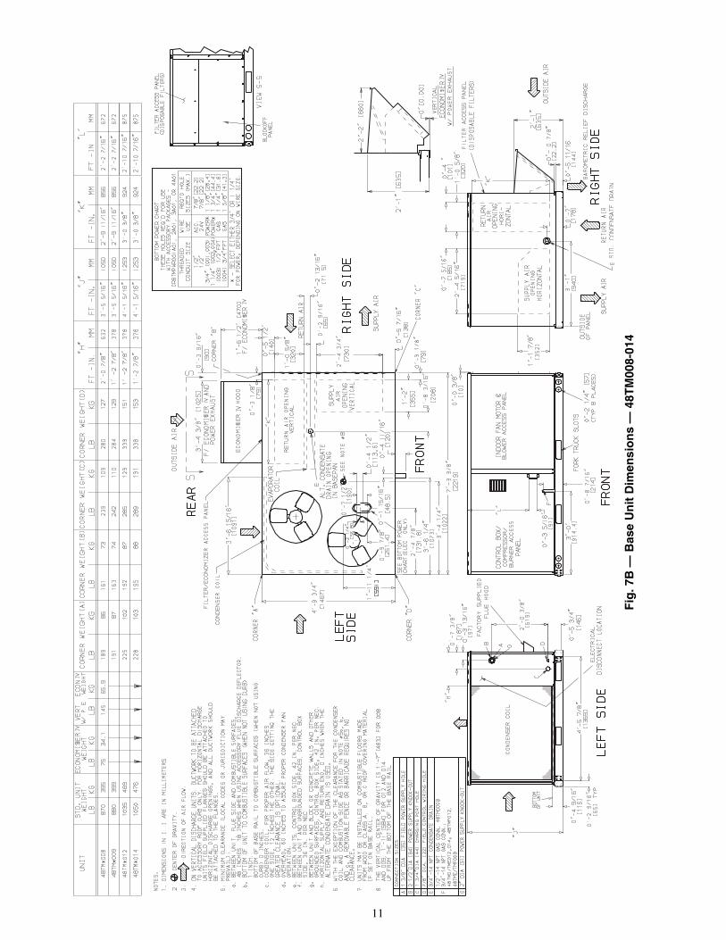
Lifting holes are provided in base rails as shown in Fig. 6,7A and 7B. Refer to rigging instructions on unit.
POSITIONING — Maintain clearance around and above unitto provide minimum distance from combustible materials,proper airflow, and service access. See Fig. 7A and 7B Notes.
Do not install unit in an indoor location. Do not locate unit airinlets near exhaust vents or other sources of contaminated air.
Be sure that unit is installed so that snow will not block thecombustion intake or flue outlet.
Unit may be installed directly on wood flooring or on ClassA, B, or C roof-covering material when roof curb is used.
Although unit is weatherproof, guard against water fromhigher level runoff and overhangs.
Position unit on roof curb so that the following clearancesare maintained: 1/4-in. clearance between roof curb and baserails on each side and duct end of unit; 35/16-in. clearancebetween roof curb and condenser section end. (See Fig. 2,section C-C.)
Locate mechanical draft system flue assembly at least 48 in.from an adjacent building or combustible material. When unitis located adjacent to public walkways, flue assembly must beat least 7 ft above grade.
Flue vent discharge must have a minimum horizontal clear-ance of 48 in. from electric and gas meters, gas regulators, andgas relief equipment.
Flue gas can deteriorate building materials. Orient unit sothat flue gas will not affect building materials.
Adequate combustion-air space must be provided for properoperation of this equipment. Be sure that installation complieswith all local codes and Section 5.3, Air for Combustionand Ventilation, NFGC (National Fuel Gas Code), ANSI(American National Standards Institute) Z223.1-latest year andaddendum Z223.1A-latest year. In Canada, installation must bein accordance with the CAN1. B149.1 and CAN1.B149.2installation codes for gas burning appliances.All panels must be in place when rigging and lifting. Unit
is not designed for handling by a fork truck. Damage tounit may result.
MAXIMUM ALLOWABLEDIFFERENCE (in.)
A-B B-C A-C0.5 1.0 1.0
Fig. 3 — Unit Leveling Tolerances
DRAIN PLUGHORIZONTALDRAIN OUTLET
NOTE: Drain plug is shown in factory-installed position.
Fig. 4 — Condensate Drain Pan (Side View)
NOTE: Trap should be deep enough to offset maximum unit staticdifference. A 4-in. trap is recommended.
Fig. 5 — Condensate Drain Piping Details

5
NOTES:1. Dimension in ( ) is in millimeters.2. Hook rigging shackles through holes in base rail as shown in
detail ‘‘A.’’ Holes in base rails are centered around the unit cen-ter of gravity. Use wooden top skid when rigging to prevent rig-ging straps from damaging unit.
3. Weights include base unit without economizer. See Tables 1Aand 1B for economizer weights.
All panels must be in place when rigging. Unit is not designed forhandling by a fork truck. Damage to unit may result.
Fig. 6 — Rigging Details
48TF, 48TMUNIT SIZE
OPERATINGWEIGHT
DIMENSIONS“A” “B” “C”
lb kg in. mm in. mm in. mm008 870 395 87.38 2219 40.25 1022 41.31 1050009 880 399 87.38 2219 40.25 1022 41.31 1050012 1035 469 87.38 2219 40.25 1022 49.31 1253014 1050 476 87.38 2219 40.25 1022 49.31 1253

6
Table 1A — Physical Data — 48TF008-014
LEGEND
*Evaporator coil fin material/condenser coil fin material. Contact your localrepresentative for details about coated fins.
†Weight of 14-in. roof curb.**Rollout switch lockout is manually reset by interrupting power to unit or
resetting thermostat.
NOTE: High-static motor not available on size 014 units.
48TF UNIT SIZE D/E/F008 D/E/F009 D/E/F012 D/E014NOMINAL CAPACITY (tons) 71/2 81/2 10 121/2OPERATING WEIGHT (lb)
UnitAl/Al* 870 880 1035 1050Al/Cu* 881 896 1057 1077Cu/Cu* 893 907 1080 1100
EconomizerEconoMi$er IV 75 75 75 75
Roof Curb† 143 143 143 143COMPRESSOR Reciprocating Reciprocating Reciprocating Scroll
Quantity 2 2 2 2No. Cylinders (per Circuit) 2 2 2 —Oil (oz) 42 ea 65 ea 54 ea 54 ea
REFRIGERANT TYPE R-22Expansion Device Fixed Orifice Metering DeviceOperating Charge (lb-oz)
Circuit 1 4-13 6-14 7- 3 8-10Circuit 2 4-14 9- 2 7-13 8- 6
CONDENSER COIL Enhanced Copper Tubes, Aluminum Lanced FinsRows...Fins/in. 1...17 2...17 2...17 2...17Total Face Area (sq ft) 20.50 18.00 20.47 25.00
CONDENSER FAN Propeller TypeNominal Cfm 6400 6400 7000 7000Quantity...Diameter (in.) 2...22 2...22 2...22 2...22Motor Hp...Rpm 1/4...1100 1/4...1100 1/4...1100 1/4...1100Watts Input (Total) 600 600 600 600
EVAPORATOR COIL Enhanced Copper Tubes, Aluminum Double-Wavy Fins, Face SplitRows...Fins/in. 3...15 3...15 3...15 4...15Total Face Area (sq ft) 8.0 8.0 10.0 11.1
EVAPORATOR FAN Centrifugal TypeQuantity...Size (in.) Std 1...15 x 15 1...15 x 15 1...15 x 15 1...15 x 15
Alt 1...15 x 15 — 1...15 x 15 1...15 x 15High-Static 1...15 x 15 1...15 x 15 1...15 x 15 —
Type Drive Std Belt Belt Belt BeltAlt Belt — Belt BeltHigh-Static Belt Belt Belt —
Nominal Cfm 3000 3100 4000 5000Maximum Continuous Bhp Std 2.40 2.40 2.40 3.70
Alt 2.40 — 2.90 5.25High-Static 3.70 3.70 5.25 —
Motor Frame Size Std 56 56 56 56Alt 56 — 56 56High-Static 56 56 56 —
Fan Rpm Range Std 590-840 685-935 685-935 860-1080Alt 685-935 — 835-1085 830-1130High-Static 860-1080 860-1080 830-1130 —
Motor Bearing Type Ball Ball Ball BallMaximum Allowable Rpm 2100 2100 2100 2100Motor Pulley Pitch Diameter Min/Max (in.) Std 2.4/3.4 2.8/3.8 2.8/3.8 4.0/5.0
Alt 2.8/3.8 — 3.4/4.4 3.1/4.1High-Static 4.0/5.0 4.0/5.0 2.8/3.8 —
Nominal Motor Shaft Diameter (in.) Std 5/8 5/8 5/8 7/8Alt 1/2 — 7/8 7/8High-Static 7/8 7/8 7/8 —
Fan Pulley Pitch Diameter (in.) Std 7.0 7.0 7.0 8.0Alt 7.0 — 7.0 5.9High-Static 8.0 8.0 5.8 —
Belt, Quantity...Type...Length (in.) Std 1...A...48 1...A...48 1...A...49 1...A...53Alt 1...A...48 — 1...A...51 1...BX...48High-Static 1...A...53 1...A...53 1...BX...48 —
Pulley Center Line Distance (in.) Std 16.75-19.25 16.75-19.25 15.85-17.50 15.85-17.50Alt 16.75-19.25 — 15.85-17.50 15.85-17.50High-Static 16.75-19.25 16.75-19.25 15.85-17.50 —
Speed Change per Full Turn of Std 50 50 50 44Movable Pulley Flange (rpm) Alt 50 — 50 50
High-Static 60 60 60 —Movable Pulley Maximum Full Turns Std 5 5 5 5
From Closed Position Alt 5 — 5 6High-Static 5 5 6 —
Factory Setting Std 5 5 5 5Alt 5 — 5 5High-Static 5 5 5 —
Factory Speed Setting (rpm) Std 590 685 685 860Alt 685 — 835 887High-Static 860 860 887 —
Fan Shaft Diameter at Pulley (in.) 1 1 1 1
Al — AluminumBhp — Brake HorsepowerCu — Copper

7
Table 1A — Physical Data — 48TF008-014 (cont)
LEGEND
*Evaporator coil fin material/condenser coil fin material. Contact your localrepresentative for details about coated fins.
†Weight of 14-in. roof curb.**Rollout switch lockout is manually reset by interrupting power to unit or
resetting thermostat.NOTE: High-static motor not available on size 014 units.
48TF UNIT SIZE D/E/F008 D/E/F009 D/E/F012 D/E014FURNACE SECTION
Rollout Switch CutoutTemp (F)** 195 195 195 195Burner Orifice Diameter(in. ...drill size)
Natural Gas Std TFD .120...31 .120...31 .120...31 .120...31TFE .120...31 .120...31 .120...31 .129...30TFF .120...31 .120...31 .129...30 —
Liquid Propane Alt TFD .096...41 .096...41 .096...41 .096...41TFE .096...41 .096...41 .096...41 .102...38TFF .096...41 .096...41 .102...38 —
Thermostat Heat AnticipatorSetting (amps)
208/230 v and 575 Stage 1 .14 .14 .14 .14Stage 2 .20 .20 .20 .20
460 v Stage 1 .14 .14 .14 .14Stage 2 .20 .20 .20 .20
Gas Input (Btuh) Stage 1 TFD 125,000 125,000 120,000 180,000TFE 120,000 120,000 180,000 200,000TFF 180,000 180,000 200,000 —
Stage 2 TFD — — 180,000 224,000TFE 180,000 180,000 224,000 250,000TFF 224,000 224,000 250,000 —
Efficiency (SteadyState) (%) 80 80 80 80
Temperature Rise Range TFD 20-50 20-50 35-65 35-65TFE 35-65 35-65 35-65 40-70TFF 45-75 45-75 40-70 —
Manifold Pressure (in. wg)Natural Gas Std 3.5 3.5 3.5 3.5Liquid Propane Alt 3.5 3.5 3.5 3.5
Gas Valve Quantity 1 1 1 1Gas Valve Pressure Range
Psig 0.180-0.487 0.180-0.487 0.180-0.487 0.180-0.487in. wg 5.0-13.5 5.0-13.5 5.0-13.5 5.0-13.5
Field Gas ConnectionSize (in.) 1/2/3/4/3/4 1/2/3/4/3/4 3/4/3/4/3/4 3/4/3/4
HIGH-PRESSURE SWITCH (psig)Standard Compressor 450 ± 50 500 ± 50Internal Relief (Differential)Cutout 428 428Reset (Auto.) 320 320
LOSS-OF-CHARGE (LOW-PRESSURE)SWITCH (psig)Cutout 7 ± 3Reset (Auto.) 22 ± 7
FREEZE PROTECTIONTHERMOSTAT (F)
Opens 30 ± 5Closes 45 ± 5
OUTDOOR-AIR INLET SCREENS Cleanable...Screen size and quantity varies by option selected.
RETURN-AIR FILTERS ThrowawayQuantity...Size (in.) 4...16 x 20 x 2 4...16 x 20 x 2 4...20 x 20 x 2 4...20 x 20 x 2
Al — AluminumBhp — Brake HorsepowerCu — Copper

8
Table 1B — Physical Data — 48TM008-014
LEGEND
*Evaporator coil fin material/condenser coil fin material. Contact your localrepresentative for details about coated fins.
†Weight of 14-in. roof curb.**Rollout switch lockout is manually reset by interrupting power to unit or
resetting thermostat.NOTE: High-static motor not available on size 014 units.
48TM UNIT SIZE D/E/F008 D/E/F009 D/E/F012 D/E014NOMINAL CAPACITY (tons) 71/2 81/2 10 121/2
OPERATING WEIGHT (lb)Unit
Al/Al* 870 880 1035 1050Al/Cu* 891 896 1057 1077Cu/Cu* 893 907 1080 1100
EconomizerEconoMi$er IV 75 75 75 75
Roof Curb† 143 143 143 143
COMPRESSOR Reciprocating Scroll Scroll ScrollQuantity 2 2 2 2No. Cylinders (per Circuit) 2 2 2 2Oil (oz) (each compressor) 42 53 50 60
REFRIGERANT TYPE R-22Expansion Device Acutrol™ Metering DeviceOperating Charge (lb-oz)
Circuit 1 7-10 7-14 8-10 9-8Circuit 2 8-2 8-5 8-8 9-5
CONDENSER COIL Enhanced Copper Tubes, Aluminum Lanced FinsRows...Fins/in. 2...17 2...17 2...17 2...17Total Face Area (sq ft) 20.50 20.50 25.00 25.00
CONDENSER FAN Propeller TypeNominal Cfm 6500 6500 7000 7000Quantity...Diameter (in.) 2...22 2...22 2...22 2...22Motor Hp...Rpm 1/4...1100 1/4...1100 1/4...1100 1/4...1100Watts Input (Total) 650 650 650 650
EVAPORATOR COIL Enhanced Copper Tubes, Aluminum Double-Wavy Fins, Face SplitRows...Fins/in. 3...15 3...15 3...15 4...15Total Face Area (sq ft) 8.9 8.9 10.0 11.1
EVAPORATOR FAN Centrifugal TypeQuantity...Size (in.) Std 1...15 x 15 1...15 x 15 1...15 x 15 1...15 x 15
Alt 1...15 x 15 — 1...15 x 15 1...15 x 15High-Static 1...15 x 15 1...15 x 15 1...15 x 15 —
Type Drive Std Belt Belt Belt BeltAlt Belt — Belt BeltHigh-Static Belt Belt Belt —
Nominal Cfm 2900 3000 3200 5000Maximum Continuous Bhp Std 2.40 2.40 2.40 3.70
Alt 2.40 — 2.90 5.25High-Static 3.70 3.70 5.25 —
Motor Frame Size Std 56 56 56 56Alt 56 — 56 56High-Static 56 56 56 —
Fan Rpm Range Std 590-840 685-935 685-935 860-1080Alt 685-935 — 835-1085 830-1130High-Static 860-1080 860-1080 830-1130 —
Motor Bearing Type Ball Ball Ball BallMaximum Allowable Rpm 2100 2100 2100 2100Motor Pulley Pitch Diameter Min/Max (in.) Std 2.4/3.4 2.8/3.8 2.8/3.8 4.0/5.0
Alt 2.8/3.8 — 3.4/4.4 3.1/4.1High-Static 4.0/5.0 4.0/5.0 2.8/3.8 —
Nominal Motor Shaft Diameter (in.) Std 5/8 5/8 5/8 7/8Alt 5/8 — 7/8 7/8High-Static 7/8 7/8 7/8 —
Fan Pulley Pitch Diameter (in.) Std 7.0 7.0 7.0 8.0Alt 7.0 — 7.0 5.9High-Static 8.0 8.0 5.8 —
Belt, Quantity...Type...Length (in.) Std 1...A...48 1...A...48 1...A...49 1...A...53Alt 1...A...48 — 1...A...51 1...BX...48High-Static 1...A...53 1...A...53 1...BX...48 —
Pulley Center Line Distance (in.) Std 16.75-19.25 16.75-19.25 15.85-17.50 15.85-17.50Alt 16.75-19.25 — 15.85-17.50 15.85-17.50High-Static 16.75-19.25 16.75-19.25 15.85-17.50 —
Speed Change per Full Turn of Std 50 50 50 44Movable Pulley Flange (rpm) Alt 50 — 50 50
High-Static 60 60 60 —Movable Pulley Maximum Full Turns Std 5 5 5 5
From Closed Position Alt 5 — 5 6High-Static 5 5 6 —
Factory Setting Std 5 5 5 5Alt 5 — 5 5High-Static 5 5 5 —
Factory Speed Setting (rpm) Std 590 685 685 860Alt 685 — 835 887High-Static 860 860 887 —
Fan Shaft Diameter at Pulley (in.) 1 1 1 1
Al — AluminumBhp — Brake HorsepowerCu — Copper

9
Table 1B — Physical Data — 48TM008-014 (cont)
LEGEND
*Evaporator coil fin material/condenser coil fin material. Contact your localrepresentative for details about coated fins.
†Weight of 14-in. roof curb.**Rollout switch lockout is manually reset by interrupting power to unit or
resetting thermostat.NOTE: High-static motor not available on size 014 units.
48TM UNIT SIZE D/E/F008 D/E/F009 D/E/F012 D/E014FURNACE SECTION
Rollout Switch CutoutTemp (F)** 195 195 195 195Burner Orifice Diameter(in. ...drill size)
Natural Gas Std TMD .120...31 .120...31 .120...31 .120...31TME .120...31 .120...31 .120...31 .129...30TMF .120...31 .120...31 .129...30 —
Liquid Propane Alt TMD .096...41 .096...41 .096...41 .096...41TME .096...41 .096...41 .096...41 .102...38TMF .096...41 .096...41 .102...38 —
Thermostat Heat AnticipatorSetting (amps)
208/230 v and 575 Stage 1 .14 .14 .14 .14Stage 2 .20 .20 .20 .20
460 v Stage 1 .14 .14 .14 .14Stage 2 .20 .20 .20 .20
Gas Input (Btuh) Stage 1 TMD 125,000 125,000 120,000 180,000TME 120,000 120,000 180,000 200,000TMF 180,000 180,000 200,000 —
Stage 2 TMD — — 180,000 224,000TME 180,000 180,000 224,000 250,000TMF 224,000 224,000 250,000 —
Efficiency (SteadyState) (%) 80 80 80 80
Temperature Rise Range TMD 20-50 20-50 35-65 35-65TME 35-65 35-65 35-65 40-70TMF 45-75 45-75 40-70 —
Manifold Pressure (in. wg)Natural Gas Std 3.5 3.5 3.5 3.5Liquid Propane Alt 3.5 3.5 3.5 3.5
Gas Valve Quantity 1 1 1 1Gas Valve Pressure Range
Psig 0.180-0.487 0.180-0.487 0.180-0.487 0.180-0.487in. wg 5.0-13.5 5.0-13.5 5.0-13.5 5.0-13.5
Field Gas ConnectionSize (in.) TMD 1/2 1/2 3/4 3/4
TME 3/4 3/4 3/4 3/4TMF 3/4 3/4 3/4 —
HIGH-PRESSURE SWITCH (psig)Standard Compressor 450 ± 50 500 ± 50Internal Relief (Differential)Cutout 428 428Reset (Auto.) 320 320
LOW-PRESSURE SWITCH (psig)Cutout 7 ± 3Reset (Auto.) 22 ± 7
FREEZE PROTECTIONTHERMOSTAT (F)
Opens 30 ± 5Closes 45 ± 5
OUTDOOR-AIR INLET SCREENS Cleanable...Screen size and quantity varies by option selected.RETURN-AIR FILTERS Throwaway
Quantity...Size (in.) 4...16 x 20 x 2 4...16 x 20 x 2 4...20 x 20 x 2 4...20 x 20 x 2
Al — AluminumBhp — Brake HorsepowerCu — Copper

10
Fig
.7A
—B
ase
Un
itD
imen
sio
ns
—48
TF
008-
014
11
Fig
.7B
—B
ase
Un
itD
imen
sio
ns
—48
TM
008-
014

12
Step 5 — Install Flue Hood — Flue hood is shippedscrewed to the burner compartment access panel. Removefrom shipping location and, using screws provided, install fluehood and screen in location shown in Fig. 8.
Step 6 — Install Gas Piping — Unit is equipped foruse with type of gas shown on nameplate. Refer to localbuilding codes, or in the absence of local codes, toANSI Z223.1-latest year and addendum Z223.1A-latest yearentitled National Fuel Gas Code. In Canada, installation mustbe in accordance with the CAN1.B149.1 and CAN1.B149.2installation codes for gas burning appliances when installinggas piping.
For natural gas applications, gas pressure at unit gas con-nection must not be less than 4.0 in. wg (5.0 in. wg in high heatunits) or greater than 13.0 in. wg while unit is operating.For liquid propane applications, the gas pressure must not beless than 5.0 in. wg or greater than 13.0 in. wg at the unitconnection.
Size gas supply piping for 0.5 in. wg maximum pressuredrop. Do not use supply pipe smaller than unit gas connection.
Support gas piping as shown in the table in Fig. 9. For ex-ample, a 3/4-in. gas pipe must have one field-fabricated supportbeam every 8 ft.
See Fig. 9 for typical pipe guide and locations of externalmanual gas shutoff valve.NOTE: If field-installed thru-the-bottom connections are used,refer to the accessory installation instructions for power wiringand gas connections. Refer to Fig. 7A and 7B for drilling holesin basepan.
Step 7 — Make Electrical Connections
FIELD POWER SUPPLY — All units except 208/230-vunits are factory wired for the voltage shown on the nameplate.If the 208/230-v unit is to be connected to a 208-v power sup-ply, the transformer must be rewired by moving the black wirefrom the 230-v 1/4-in. spade terminal on the transformer andconnecting it to the 208-v 1/4-in. spade terminal from thetransformer.
Refer to unit label diagram for additional information. Pig-tails are provided for field service.
When installing units, provide a disconnect per NEC. Usecopper conductors only when splice connectors are used.
All field wiring must comply with NEC and local require-ments. In Canada, electrical connections must be in accordancewith CSA (Canadian Standards Association) C22.1 CanadianElectrical Code Part One.
Install conduit through side panel openings indicated inFig. 7A and 7B. Route power lines through connector to termi-nal connections as shown in Fig. 10.
On 3-phase units, voltages between phases must be bal-anced within 2% and the current within 10%. Use the formulashown in Tables 2A-2D, Note 2 to determine the percentage ofvoltage imbalance. Operation on improper line voltage or ex-cessive phase imbalance constitutes abuse and may cause dam-age to electrical components. Such operation would invalidateany applicable Carrier warranty.NOTE: If field-installed thru-the-bottom connections are used,refer to the accessory installation instructions for power wiringand gas connections. Refer to Fig. 7A and 7B for drilling holesin basepan.FIELD CONTROL WIRING — Install a Carrier-approvedaccessory thermostat assembly according to installation in-structions included with the accessory. Locate thermostatassembly on a solid wall in the conditioned space to sense aver-age temperature in accordance with thermostat installationinstructions.NOTE: For wire runs up to 50 ft, use no. 18 AWG (AmericanWire Gage) insulated wire (35 C minimum). For 50 to 75 ft,use no. 16 AWG insulated wire (35 C minimum). For over75 ft, use no. 14 AWG insulated wire (35 C minimum). Allwire larger than no. 18 AWG cannot be directly connected tothe thermostat and will require a junction box and splice at thethermostat.
When connecting gas piping to gas valve inlet, use prop-erly sized back-up wrench to prevent valve damage.
Unit cabinet must have an uninterrupted, unbroken electri-cal ground to minimize the possibility of personal injury ifan electrical fault should occur. This ground may consist ofelectrical wire connected to unit ground lug in control com-partment, or conduit approved for electrical ground wheninstalled in accordance with NEC (National ElectricalCode), ANSI/NFPA (National Fire Protection Associa-tion), latest edition, and local electrical codes. Do not usegas piping as an electrical ground. Failure to follow thiswarning could result in the installer being liable for per-sonal injury of others.
Fig. 8 — Flue Hood Details
Fig. 9 — Gas Piping Guide (With AccessoryThru-the-Curb Service Connections)
SPACING OF SUPPORTS
STEEL PIPENOMINALDIAMETER
(in.)
XDIMENSION
(feet)
1/23/4 or 1
11/4 or larger
68
10
LEGEND
*Field supplied.NOTE: Follow all local codes.
NFGC — National Fuel Gas Code

13
Route thermostat cable or equivalent single leads of coloredwire from thermostat subbase terminals to low-voltage connec-tions on unit (shown in Fig. 11A and 11B) as described in Steps1-4 below.
1. If unit is mounted on roof curb and accessory thru-the-curb service plate connection is used, route wire throughconnection plate.
2. Pass control wires through the hole provided on unit(see connection D in Connection Sizes table in Fig. 7Aand 7B).
3. Feed wires through the raceway built into the corner postto the 24-v barrier located on the left side of the controlbox. See Fig. 12. The raceway provides the UL-required(Underwriters’ Laboratories) clearance between high-and low-voltage wiring.
4. Connect thermostat wires to screw terminals on low-voltage connection board.
HEAT ANTICIPATOR SETTINGS — Set heat anticipatorsettings at 0.14 amp for the first stage and 0.20 amp for second-stage heating.
Fig. 10 — Power Wiring Connections
LEGENDC — ContactorCOMPS — CompressorsIFC — Indoor (Evaporator)
Fan ContactorNEC — National Electrical CodeTB — Terminal Block
Terminal BlockConnectionSplice Connection(Factory Supplied)Field WiringFactory Wiring
W2
C
Y1
G
R
Y2
W1
C
G
R
Y2
W1
X
W2
C
Y1
G
R
Y2
W1
X
24 VAC
RMTOCC
CMPSAFE
FSD
NOT USED
C
X
SFS
THERMOSTAT CONTROLCONNECTION
BOARDBOARDCONNECTION
CONTROL
Fig. 11B — Low Voltage Connections(Units with PremierLink™ Controls)
WIRECONNECTIONSTOLOW-VOLTAGESECTION(CONNECTIONBOARD)
COOL STAGE 1
FAN
HEAT STAGE 1
COOL STAGE 2
HEAT STAGE 2
24 VAC HOT
24 VAC COM
N/A
OUTDOOR AIR
SENSOR
Y1/W2
G
W/W1
Y/Y2
O/W2
R
C
S1
S2
THERMOSTAT DIPSWITCH SETTINGS
R
G
Y1
Y2
W1
W2
C
IPD/X
ONOFF
A B C DLEGEND
NOTE: Underlined letter indicates active thermostat output whenconfigured for A/C operation.
Fig. 11A — Low-Voltage Connections With orWithout Economizer or Two-Position Damper
Field Wiring

14
Table 2A — Electrical Data — 48TF Units (Without Convenience Outlet)
LEGEND
*The values listed in this table do not include power exhaust. See tablebelow for power exhaust requirements.
†Used to determine minimum disconnect per NEC.**Fuse or HACR circuit breaker.
††Fuse only.***Data shown in table is for Compressor no. 1.
208/230-3-60: Compressor no. 2 RLA is 14.1 amps and LRA is 105 amps.460-3-60: Compressor no. 2 RLA is 7.1 amps and LRA is 55 amps.575-3-60: Compressor no. 2 RLA is 6.4 amps and LRA is 40 amps.
NOTES:1. In compliance with NEC requirements for multimotor and combination load
equipment (refer to NEC Articles 430 and 440), the overcurrent protectivedevice for the unit shall be fuse or HACR breaker. Canadian units may befuse or circuit breaker.
2. Unbalanced 3-Phase Supply VoltageNever operate a motor where a phase imbalance in supply voltage isgreater than 2%. Use the following formula to determine the percent of volt-age imbalance.% Voltage Imbalance
Example: Supply voltage is 460-3-60.
AB = 452 vBC = 464 vAC = 455 v
= 457Determine maximum deviation from average voltage.(AB) 457 – 452 = 5 v(BC) 464 – 457 = 7 v(AC) 457 – 455 = 2 v
Maximum deviation is 7 v.
Determine percent of voltage imbalance.
% Voltage Imbalance = 100 x
= 1.53%This amount of phase imbalance is satisfactory as it is below the maximumallowable 2%.
POWER EXHAUST ELECTRICAL DATA
N/A — Not available
NOTE: If a single power source is to be used, size wire to include powerexhaust MCA and MOCP.Check MCA and MOCP when power exhaust is powered through the unit.Determine the new MCA including the power exhaust using the followingformula:MCA New = MCA unit only + MCA of Power ExhaustFor example, using a 48TF008 unit with MCA = 40.1 and MOCP = 45, withCRPWREXH030A01 power exhaust.MCA New = 40.1 amps + 1.6 amps = 41.7 ampsIf the new MCA does not exceed the published MOCP, then MOCP would notchange. The MOCP in this example is 45 amps and the MCA New is below45; therefore the MOCP is acceptable. If “MCA New” is larger than the pub-lished MOCP, raise the MOCP to the next larger size. For separate power, theMOCP for the power exhaust will be 15 amps per NEC.
48TFUNIT SIZE
NOMINALVOLTAGE
IFMTYPE
VOLTAGERANGE
COMPR(ea) OFM (ea) IFM COMBUSTION
FAN MOTORFLA
POWER SUPPLY* DISCONNECTSIZE†
Min Max RLA LRA Qty Hp FLA FLA MCA MOCP** FLA LRA
008(71/2 Tons)
208/230-3-60Std
187 254 14.0 91.0 2 1/4 1.45.8
.640.1/40.1 45/45 42/42 229/229
Alt 5.8 40.1/40.1 45/45 42/42 229/229High 10.6 44.9/44.9 50/50 48/48 273/273
460-3-60Std
414 508 6.4 42.0 2 1/4 0.72.6
.318.4 20 19 108
Alt 2.6 18.4 20 19 108High 4.8 20.6 25 22 130
575-3-60Std
518 632 5.2 39.0 2 1/4 0.72.6
.314.9 20 16 97
Alt 2.6 14.9 20 16 97High 4.8 16.7 20 18 114
009(81/2 Tons)
208/230-3-60Std
187 254 16.0 137.0 2 1/4 1.45.8
.644.6/44.6 50/50 47/47 321/321
High 10.6 49.4/49.4 60/60 52/52 365/365
460-3-60Std
414 508 8.3 69.0 2 1/4 0.72.6
.322.7 25 24 162
High 4.8 24.9 30 26 184
575-3-60Std
518 632 6.4 58.0 2 1/4 0.72.6
.317.6 20 18 135
High 4.8 19.4 25 20 152
012(10 Tons)
208/230-3-60Std
187 254 15.8 130.0 2 1/4 1.45.8
.644.2/44.2 50/50 46/46 307/307
Alt 7.5 45.9/45.9 50/50 48/48 326/326High 15.0 53.4/53.4 60/60 57/57 374/374
460-3-60Std
414 508 7.9 64.0 2 1/4 0.72.6
.321.8 25 23 152
Alt 3.4 22.6 25 24 191High 7.4 26.6 30 28 185
575-3-60Std
518 632 6.6 52.0 2 1/4 0.72.6
.318.1 25 19 123
Alt 3.4 18.7 25 20 155High 7.4 21.9 30 23 150
014(121/2 Tons)
208/230-3-60Std
187 254 23.0 146.0 2 1/4 1.410.6
.665.2/65.2 80/80†† 68/68 383/383
Alt 15.0 69.6/69.6 80/80†† 73/73 406/406
460-3-60Std
414 508 10.4 73.0 2 1/4 0.74.8
.329.6 40 31 192
Alt 7.4 32.2 45 34 203
575-3-60Std
518 632 8.3 58.4 2 1/4 0.74.8
.323.6 30 25 154
Alt 7.4 25.7 30 27 162
FLA — Full Load AmpsHACR — Heating, Air Conditioning and RefrigerationIFM — Indoor (Evaporator) Fan MotorLRA — Locked Rotor AmpsMCA — Minimum Circuit AmpsMOCP — Maximum Overcurrent ProtectionNEC — National Electrical CodeOFM — Outdoor (Condenser) Fan MotorRLA — Rated Load Amps
= 100 x max voltage deviation from average voltageaverage voltage
Average Voltage =452 + 464 + 455
3
=1371
3
IMPORTANT: If the supply voltage phase imbalance is more than 2%, con-tact your local electric utility company immediately.
POWER EXHAUSTPART NO.
MCA(230 v)
MCA(460 v)
MCA(575 v)
MOCP(for separate
power source)CRPWREXH021A01 N/A 0.9 N/A 15CRPWREXH022A01 3.3 N/A 1.32 15CRPWREXH023A01 N/A 1.8 N/A 15CRPWREXH024A01 1.6 N/A 0.64 15CRPWREXH025A01 N/A 0.9 N/A 15CRPWREXH026A01 3.3 N/A 1.32 15CRPWREXH027A01 N/A 1.8 N/A 15CRPWREXH028A01 1.7 N/A 0.68 15CRPWREXH029A01 N/A 1.0 N/A 15CRPWREXH030A01 1.6 N/A 0.64 15
7457

15
Table 2B — Electrical Data — 48TF Units (With Convenience Outlet)
LEGEND
*The values listed in this table do not include power exhaust. See tablebelow for power exhaust requirements.
†Used to determine minimum disconnect per NEC.**Fuse or HACR circuit breaker.
††Fuse only.***Data shown in table is for Compressor no. 1.
208/230-3-60: Compressor no. 2 RLA is 14.1 amps and LRA is 105 amps.460-3-60: Compressor no. 2 RLA is 7.1 amps and LRA is 55 amps.575-3-60: Compressor no. 2 RLA is 6.4 amps and LRA is 40 amps.
NOTES:1. In compliance with NEC requirements for multimotor and combination load
equipment (refer to NEC Articles 430 and 440), the overcurrent protectivedevice for the unit shall be fuse or HACR breaker. Canadian units may befuse or circuit breaker.
2. Unbalanced 3-Phase Supply VoltageNever operate a motor where a phase imbalance in supply voltage isgreater than 2%. Use the following formula to determine the percent of volt-age imbalance.% Voltage Imbalance
Example: Supply voltage is 460-3-60.
AB = 452 vBC = 464 vAC = 455 v
= 457Determine maximum deviation from average voltage.(AB) 457 – 452 = 5 v(BC) 464 – 457 = 7 v(AC) 457 – 455 = 2 v
Maximum deviation is 7 v.
Determine percent of voltage imbalance.
% Voltage Imbalance = 100 x
= 1.53%This amount of phase imbalance is satisfactory as it is below the maximumallowable 2%.
POWER EXHAUST ELECTRICAL DATA
N/A — Not available
NOTE: If a single power source is to be used, size wire to include powerexhaust MCA and MOCP.Check MCA and MOCP when power exhaust is powered through the unit.Determine the new MCA including the power exhaust using the followingformula:MCA New = MCA unit only + MCA of Power ExhaustFor example, using a 48TF008 unit with MCA = 40.1 and MOCP = 45, withCRPWREXH030A01 power exhaust.MCA New = 40.1 amps + 1.6 amps = 41.7 ampsIf the new MCA does not exceed the published MOCP, then MOCP would notchange. The MOCP in this example is 45 amps and the MCA New is below45; therefore the MOCP is acceptable. If “MCA New” is larger than the pub-lished MOCP, raise the MOCP to the next larger size. For separate power, theMOCP for the power exhaust will be 15 amps per NEC.
48TFUNIT SIZE
NOMINALVOLTAGE
IFMTYPE
VOLTAGERANGE
COMPR(ea) OFM (ea) IFM COMBUSTION
FAN MOTORFLA
POWER SUPPLY* DISCONNECTSIZE†
Min Max RLA LRA Qty Hp FLA FLA MCA MOCP** FLA LRA
008(71/2 Tons)
208/230-3-60Std
187 254 14.0 91.0 2 1/4 1.45.8
.646.1/46.1 50/50 48/48 233/233
Alt 5.8 46.1/46.1 50/50 48/48 233/233High 10.6 50.9/50.9 60/60 53/53 273/273
460-3-60Std
414 508 6.4 42.0 2 1/4 0.72.6
.324.1 25 22 110
Alt 2.6 24.1 25 22 110High 4.8 23.3 30 24 132
575-3-60Std
518 632 5.2 39.0 2 1/4 0.72.6
.320.9 25 18 99
Alt 2.6 20.9 25 18 99High 4.8 19.4 25 20 117
009(81/2 Tons)
208/230-3-60Std
187 254 16.0 137.0 2 1/4 1.45.8
.650.6/50.6 60/60 52/52 325/325
High 10.6 55.4/55.4 60/60 58/58 369/369
460-3-60Std
414 508 8.3 69.0 2 1/4 0.72.6
.325.4 30 26 164
High 4.8 27.6 35 29 138
575-3-60Std
518 632 6.4 58.0 2 1/4 0.72.6
.320.3 25 20 137
High 4.8 22.1 30 22 155
012(10 Tons)
208/230-3-60Std
187 254 15.8 130.0 2 1/4 1.45.8
.650.2/50.2 60/60 52/52 311/311
Alt 7.5 51.9/51.9 60/60 54/54 330/330High 15.0 59.4/59.4 70/70†† 62/62 378/378
460-3-60Std
414 508 7.9 64.0 2 1/4 0.72.6
.327.8 30 25 154
Alt 3.4 25.3 30 26 193High 7.4 29.3 35 31 187
575-3-60Std
518 632 6.6 52.0 2 1/4 0.72.6
.324.1 25 21 109
Alt 3.4 24.7 25 22 141High 7.4 24.6 30 25 136
014(121/2 Tons)
208/230-3-60Std
187 254 23.0 146.0 2 1/4 1.410.6
.671.2/71.2 80/80†† 74/74 387/387
Alt 15.0 75.6/75.6 80/80†† 79/79 410/410
460-3-60Std
414 508 10.4 73.0 2 1/4 0.74.8
.335.6 40 34 194
Alt 7.4 34.9 40 37 205
575-3-60Std
518 632 8.3 58.4 2 1/4 0.74.8
.329.6 35 27 156
Alt 7.4 31.7 35 29 165
FLA — Full Load AmpsHACR — Heating, Air Conditioning and RefrigerationIFM — Indoor (Evaporator) Fan MotorLRA — Locked Rotor AmpsMCA — Minimum Circuit AmpsMOCP — Maximum Overcurrent ProtectionNEC — National Electrical CodeOFM — Outdoor (Condenser) Fan MotorRLA — Rated Load Amps
= 100 x max voltage deviation from average voltageaverage voltage
Average Voltage =452 + 464 + 455
3
=1371
3
IMPORTANT: If the supply voltage phase imbalance is more than 2%, con-tact your local electric utility company immediately.
POWER EXHAUSTPART NO.
MCA(230 v)
MCA(460 v)
MCA(575 v)
MOCP(for separate
power source)CRPWREXH021A01 N/A 0.9 N/A 15CRPWREXH022A01 3.3 N/A 1.32 15CRPWREXH023A01 N/A 1.8 N/A 15CRPWREXH024A01 1.6 N/A 0.64 15CRPWREXH025A01 N/A 0.9 N/A 15CRPWREXH026A01 3.3 N/A 1.32 15CRPWREXH027A01 N/A 1.8 N/A 15CRPWREXH028A01 1.7 N/A 0.68 15CRPWREXH029A01 N/A 1.0 N/A 15CRPWREXH030A01 1.6 N/A 0.64 15
7457

16
Table 2C — Electrical Data — 48TM Units (Without Convenience Outlet)
LEGEND
*The values listed in this table do not include power exhaust. See tablebelow for power exhaust requirements.
†Used to determine minimum disconnect per NEC.**Fuse or HACR circuit breaker.
††Fuse only.***Data shown in table is for Compressor no. 1.
208/230-3-60: Compressor no. 2 RLA is 14.1 amps and LRA is 105 amps.460-3-60: Compressor no. 2 RLA is 7.1 amps and LRA is 55 amps.575-3-60: Compressor no. 2 RLA is 6.4 amps and LRA is 40 amps.
NOTES:1. In compliance with NEC requirements for multimotor and combination load
equipment (refer to NEC Articles 430 and 440), the overcurrent protectivedevice for the unit shall be fuse or HACR breaker. Canadian units may befuse or circuit breaker.
2. Unbalanced 3-Phase Supply VoltageNever operate a motor where a phase imbalance in supply voltage isgreater than 2%. Use the following formula to determine the percent of volt-age imbalance.% Voltage Imbalance
Example: Supply voltage is 460-3-60.
AB = 452 vBC = 464 vAC = 455 v
= 457Determine maximum deviation from average voltage.(AB) 457 – 452 = 5 v(BC) 464 – 457 = 7 v(AC) 457 – 455 = 2 v
Maximum deviation is 7 v.
Determine percent of voltage imbalance.
% Voltage Imbalance = 100 x
= 1.53%This amount of phase imbalance is satisfactory as it is below the maximumallowable 2%.
POWER EXHAUST ELECTRICAL DATA
N/A — Not available
NOTE: If a single power source is to be used, size wire to include powerexhaust MCA and MOCP.Check MCA and MOCP when power exhaust is powered through the unit.Determine the new MCA including the power exhaust using the followingformula:MCA New = MCA unit only + MCA of Power ExhaustFor example, using a 48TF008 unit with MCA = 40.1 and MOCP = 45, withCRPWREXH030A01 power exhaust.MCA New = 40.1 amps + 1.6 amps = 41.7 ampsIf the new MCA does not exceed the published MOCP, then MOCP would notchange. The MOCP in this example is 45 amps and the MCA New is below45; therefore the MOCP is acceptable. If “MCA New” is larger than the pub-lished MOCP, raise the MOCP to the next larger size. For separate power, theMOCP for the power exhaust will be 15 amps per NEC.
48TMUNIT SIZE
NOMINALVOLTAGE
IFMTYPE
VOLTAGERANGE
COMPR(ea)
OFM(ea) IFM COMBUSTION
FAN MOTORFLA
POWER SUPPLY* DISCONNECTSIZE†
Min Max Qty RLA LRA Qty Hp FLA FLA MCA MOCP** FLA LRA
008(71/2 Tons)
208/230-3-60Std
187 254 2 14.0 91.0 2 1/4 1.45.8
.640.1/40.1 45/45 42/42 229/229
Alt 5.8 40.1/40.1 45/45 42/42 229/229High 10.6 44.9/44.9 50/50 48/48 273/273
460-3-60Std
414 508 2 6.4 42.0 2 1/4 0.72.6
.318.4 20 19 108
Alt 2.6 18.4 20 19 108High 4.8 20.6 25 22 130
575-3-60Std
518 632 2 5.2 39.0 2 1/4 0.72.6
.314.9 20 16 97
Alt 2.6 14.9 20 16 97High 4.8 16.7 20 18 114
009(81/2 Tons)
208/230-3-60Std
187 254 2 17.3*** 120.0*** 2 1/4 1.45.8
.644.3/44.3 50/50 46/46 272/272
High 10.6 49.1/49.1 60/60 52/52 316/316
460-3-60Std
414 508 2 7.9*** 70.0*** 2 1/4 0.72.6
.321.0 25 22 149
High 4.8 23.2 30 24 171
575-3-60Std
518 632 2 5.5*** 50.0*** 2 1/4 0.72.6
.316.7 20 17 109
High 4.8 18.5 25 19 126
012(10 Tons)
208/230-3-60Std
187 254 2 16.0 125.0 2 1/4 1.45.8
.644.6/44.6 50/50 47/47 297/297
Alt 7.5 46.3/46.3 60/60 49/49 316/316High 15.0 53.4/53.4 60/60 57/57 374/374
460-3-60Std
414 508 2 8.0 62.5 2 1/4 0.72.6
.322.0 25 24 188
Alt 3.4 22.8 25 24 191High 7.4 26.8 30 29 182
575-3-60Std
518 632 2 6.3 50.0 2 1/4 0.72.6
.317.4 20 18 119
Alt 3.4 18.0 20 19 151High 7.4 21.2 25 23 146
014(121/2 Tons)
208/230-3-60Std
187 254 2 19.0 156.0 2 1/4 1.410.6
.656.2/56.2 70/70†† 59/59 359/359
Alt 15.0 60.6/60.6 70/70†† 64/64 378/378
460-3-60Std
414 508 2 9.0 75.0 2 1/4 0.74.8
.326.5 30 28 174
Alt 7.4 29.1 35 31 213
575-3-60Std
518 632 2 7.4 54.0 2 1/4 0.74.8
.321.6 25 23 127
Alt 7.4 23.7 30 25 159
FLA — Full Load AmpsHACR — Heating, Air Conditioning and RefrigerationIFM — Indoor (Evaporator) Fan MotorLRA — Locked Rotor AmpsMCA — Minimum Circuit AmpsMOCP — Maximum Overcurrent ProtectionNEC — National Electrical CodeOFM — Outdoor (Condenser) Fan MotorRLA — Rated Load Amps
= 100 xmax voltage deviation from average voltage
average voltage
Average Voltage =452 + 464 + 455
3
=1371
3
IMPORTANT: If the supply voltage phase imbalance is more than 2%,contact your local electric utility company immediately.
POWER EXHAUSTPART NO.
MCA(230 v)
MCA(460 v)
MCA(575 v)
MOCP(for separate
power source)CRPWREXH021A01 N/A 0.9 N/A 15CRPWREXH022A01 3.3 N/A 1.32 15CRPWREXH023A01 N/A 1.8 N/A 15CRPWREXH024A01 1.6 N/A 0.64 15CRPWREXH025A01 N/A 0.9 N/A 15CRPWREXH026A01 3.3 N/A 1.32 15CRPWREXH027A01 N/A 1.8 N/A 15CRPWREXH028A01 1.7 N/A 0.68 15CRPWREXH029A01 N/A 1.0 N/A 15CRPWREXH030A01 1.6 N/A 0.64 15
7457

17
Table 2D — Electrical Data — 48TM Units (With Convenience Outlet)
LEGEND
*The values listed in this table do not include power exhaust. See tablebelow for power exhaust requirements.
†Used to determine minimum disconnect per NEC.**Fuse or HACR circuit breaker.
††Fuse only.***Data shown in table is for Compressor no. 1.
208/230-3-60: Compressor no. 2 RLA is 14.1 amps and LRA is 105 amps.460-3-60: Compressor no. 2 RLA is 7.1 amps and LRA is 55 amps.575-3-60: Compressor no. 2 RLA is 6.4 amps and LRA is 40 amps.
NOTES:1. In compliance with NEC requirements for multimotor and combination load
equipment (refer to NEC Articles 430 and 440), the overcurrent protectivedevice for the unit shall be fuse or HACR breaker. Canadian units may befuse or circuit breaker.
2. Unbalanced 3-Phase Supply VoltageNever operate a motor where a phase imbalance in supply voltage isgreater than 2%. Use the following formula to determine the percent of volt-age imbalance.% Voltage Imbalance
Example: Supply voltage is 460-3-60.
AB = 452 vBC = 464 vAC = 455 v
= 457Determine maximum deviation from average voltage.(AB) 457 – 452 = 5 v(BC) 464 – 457 = 7 v(AC) 457 – 455 = 2 v
Maximum deviation is 7 v.
Determine percent of voltage imbalance.
% Voltage Imbalance = 100 x
= 1.53%This amount of phase imbalance is satisfactory as it is below the maximumallowable 2%.
POWER EXHAUST ELECTRICAL DATA
N/A — Not available
NOTE: If a single power source is to be used, size wire to include powerexhaust MCA and MOCP.Check MCA and MOCP when power exhaust is powered through the unit.Determine the new MCA including the power exhaust using the followingformula:MCA New = MCA unit only + MCA of Power ExhaustFor example, using a 48TF008 unit with MCA = 40.1 and MOCP = 45, withCRPWREXH030A01 power exhaust.MCA New = 40.1 amps + 1.6 amps = 41.7 ampsIf the new MCA does not exceed the published MOCP, then MOCP would notchange. The MOCP in this example is 45 amps and the MCA New is below45; therefore the MOCP is acceptable. If “MCA New” is larger than the pub-lished MOCP, raise the MOCP to the next larger size. For separate power, theMOCP for the power exhaust will be 15 amps per NEC.
48TMUNIT SIZE
NOMINALVOLTAGE
IFMTYPE
VOLTAGERANGE
COMPR(ea)
OFM(ea) IFM COMBUSTION
FAN MOTORFLA
POWER SUPPLY* DISCONNECTSIZE†
Min Max Qty RLA LRA Qty Hp FLA FLA MCA MOCP** FLA LRA
008(71/2 Tons)
208/230-3-60Std
187 254 2 14.0 91.0 2 1/4 1.45.8
.644.9/44.9 50/50 48/48 234/234
Alt 5.8 44.9/44.9 50/50 48/48 234/234High 10.6 49.7/49.7 60/60 53/53 277/277
460-3-60Std
414 508 2 6.4 42.0 2 1/4 0.72.6
.320.6 25 22 110
Alt 2.6 20.6 25 22 110High 4.8 22.8 30 24 132
575-3-60Std
518 632 2 5.2 39.0 2 1/4 0.72.6
.316.6 20 18 99
Alt 2.6 16.6 20 18 99High 4.8 18.4 20 20 116
009(81/2 Tons)
208/230-3-60Std
187 254 2 17.3*** 120.0*** 2 1/4 1.45.8
.649.1/49.1 60/60 52/52 277/277
High 10.6 53.9/53.9 60/60 57/57 320/320
460-3-60Std
414 508 2 7.9*** 70.0*** 2 1/4 0.72.6
.323.2 30 24 151
High 4.8 25.4 30 27 173
575-3-60Std
518 632 2 5.5*** 50.0*** 2 1/4 0.72.6
.318.4 25 19 111
High 4.8 20.2 25 21 128
012(10 Tons)
208/230-3-60Std
187 254 2 16.0 125.0 2 1/4 1.45.8
.649.4/49.4 60/60 52/52 302/302
Alt 7.5 51.9/51.9 60/60 54/54 321/321High 15.0 58.6/58.6 70/70†† 63/63 369/369
460-3-60Std
414 508 2 8.0 62.5 2 1/4 0.72.6
.324.2 30 26 151
Alt 3.4 25.0 30 26 190High 7.4 29.0 35 31 184
575-3-60Std
518 632 2 6.3 50.0 2 1/4 0.72.6
.319.1 25 20 121
Alt 3.4 19.7 25 21 152High 7.4 22.9 25 25 148
014(121/2 Tons)
208/230-3-60Std
187 254 2 19.0 156.0 2 1/4 1.410.6
.661.0/61.0 70/70†† 65/65 364/364
Alt 15.0 65.4/65.4 80/80†† 70/70 383/383
460-3-60Std
414 508 2 9.0 75.0 2 1/4 0.74.8
.328.7 35 30 176
Alt 7.4 31.3 35 33 215
575-3-60Std
518 632 2 8.3 58.4 2 1/4 0.74.8
.323.3 30 25 129
Alt 7.4 25.4 30 27 160
FLA — Full Load AmpsHACR — Heating, Air Conditioning and RefrigerationIFM — Indoor (Evaporator) Fan MotorLRA — Locked Rotor AmpsMCA — Minimum Circuit AmpsMOCP — Maximum Overcurrent ProtectionNEC — National Electrical CodeOFM — Outdoor (Condenser) Fan MotorRLA — Rated Load Amps
= 100 xmax voltage deviation from average voltage
average voltage
Average Voltage =452 + 464 + 455
3
=1371
3
IMPORTANT: If the supply voltage phase imbalance is more than 2%,contact your local electric utility company immediately.
POWER EXHAUSTPART NO.
MCA(230 v)
MCA(460 v)
MCA(575 v)
MOCP(for separate
power source)CRPWREXH021A01 N/A 0.9 N/A 15CRPWREXH022A01 3.3 N/A 1.32 15CRPWREXH023A01 N/A 1.8 N/A 15CRPWREXH024A01 1.6 N/A 0.64 15CRPWREXH025A01 N/A 0.9 N/A 15CRPWREXH026A01 3.3 N/A 1.32 15CRPWREXH027A01 N/A 1.8 N/A 15CRPWREXH028A01 1.7 N/A 0.68 15CRPWREXH029A01 N/A 1.0 N/A 15CRPWREXH030A01 1.6 N/A 0.64 15
7457

18
Step 8 — Adjust Factory-Installed OptionsCONVENIENCE OUTLET — An optional convenience out-let provides power for rooftop use. For maintenance personnelsafety, the convenience outlet power is off when the unit dis-connect is off. Adjacent unit outlets may be used for servicetools. An optional “Hot Outlet” is available from the factory asa special order item.NOVAR CONTROLS — Optional Novar controls (ETM3051)are available for replacement or new construction jobs.MANUAL OUTDOOR-AIR DAMPER — The outdoor-airhood and screen are attached to the basepan at the bottom ofthe unit for shipping.Assembly:
1. Determine quantity of ventilation required for building.Record amount for use in Step 8.
2. Remove filter access panel by raising panel and swingingpanel outward. Panel is now disengaged from track andcan be removed. No tools are required to remove the filteraccess panel. Remove outdoor-air opening panel. Savepanels and screws. See Fig. 13.
3. Separate hood and screen from basepan by removing thescrews and brackets securing them. Save all screws anddiscard brackets.
4. Replace outdoor air opening panel with screws savedfrom Step 2.
5. Place hood on front of outdoor-air opening panel. SeeFig. 14 for hood details. Secure top of hood with the6 screws removed in Step 3. See Fig. 15.
6. Remove and save 6 screws (3 on each side) from sides ofthe manual outdoor-air damper.
7. Align screw holes on hood with screw holes on side ofmanual outdoor-air damper. See Fig. 14 and 15. Securehood with 6 screws from Step 6.
8. Adjust minimum position setting of the damper blade byadjusting the manual outdoor-air adjustment screws onthe front of the damper blade. See Fig. 13. Slide bladevertically until it is in the appropriate position determinedby Fig. 16. Tighten screws.
9. Remove and save screws currently on sides of hood.Insert screens. Secure screens to hood using the screws.See Fig. 15.
10. Replace filter access panel. Ensure filter access panelslides along the tracks and is securely engaged.
INTEGRATEDGAS UNITCONTROLLER(IGC)
RACEWAY
UNIT LOW VOLTAGECONNECTIONBOARD
COMPRESSORNO.1
COMPRESSORNO. 2
Fig. 12 — Field Control Wiring Racewayand Compressor Location
OUTDOORAIR OPENINGPANEL
3 SCREWS(SIDE)
Fig. 13 — Damper Panel with ManualOutdoor-Air Damper Installed

19
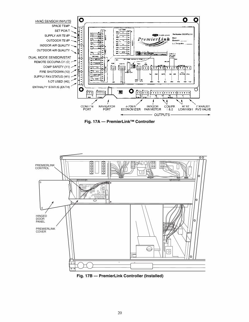
PREMIERLINK™ CONTROL — The PremierLink control-ler is compatible with Carrier Comfort Network® (CCN)devices. This control is designed to allow users the access andability to change factory-defined settings, thus expanding thefunction of the standard unit control board. Carrier’s diagnosticstandard tier display tools such as Navigator™ or ScrollingMarquee can be used with the PremierLink controller.
The PremierLink controller (see Fig. 17A and 17B) requiresthe use of a Carrier electronic thermostat or a CCN connectionfor time broadcast to initiate its internal timeclock. This isnecessary for broadcast of time of day functions (occupied/unoccupied). No sensors are supplied with the field-mountedPremierLink control. The factory-installed PremierLink con-trol includes only the supply-air sensor (SAT) and the outdoorair temperature sensor (OAT) as standard. An indoor air quality(CO2) sensor can be added as an option. Refer to Table 3 forsensor usage. Refer to Fig. 18 for PremierLink controllerwiring. The PremierLink control may be mounted in thecontrol panel or an area below the control panel.NOTE: PremierLink controller versions 1.3 and later areshipped in Sensor mode. If used with a thermostat, thePremierLink controller must be configured to Thermostatmode.Install the Supply Air Temperature Sensor (SAT) — Whenthe unit is supplied with a factory-mounted PremierLink con-trol, the supply-air temperature (SAT) sensor (33ZCSENSAT)is factory-supplied and wired. The wiring is routed from thePremierLink control over the control box, through a grommet,into the fan section, down along the back side of the fan, andalong the fan deck over to the supply-air opening.
The SAT probe is wire-tied to the supply-air opening (on thehorizontal opening end) in its shipping position. Remove thesensor for installation. Re-position the sensor in the flange ofthe supply-air opening or in the supply air duct (as required bylocal codes). Drill or punch a 1/2-in. hole in the flange or duct.Use two field-supplied, self-drilling screws to secure the sensorprobe in a horizontal orientation.NOTE: The sensor must be mounted in the discharge airstreamdownstream of the cooling coil and any heating devices. Besure the probe tip does not come in contact with any of the unitor heat surfaces.Outdoor Air Temperature Sensor (OAT) — When the unit issupplied with a factory-mounted PremierLink control, theoutdoor-air temperature sensor (OAT) is factory-supplied andwired.Install the Indoor Air Quality (CO2) Sensor — Mount theoptional indoor air quality (CO2) sensor according to manufac-turer specifications.
A separate field-supplied transformer must be used to pow-er the CO2 sensor.
Wire the CO2 sensor to the COM and IAQI terminals of J5on the PremierLink controller. Refer to the PremierLink Instal-lation, Start-Up, and Configuration Instructions for detailedwiring and configuration information.
Fig. 14 — Outdoor-Air Hood Details
Fig. 15 — Optional Manual Outdoor-Air Damperwith Hood Attached
HOOD
NOTSHOWN)
Fig. 16 — Outdoor-Air Damper Position Setting
20
Fig. 17A — PremierLink™ Controller
PREMIERLINKCONTROL
PREMIERLINKCOVER
HINGEDDOORPANEL
Fig. 17B — PremierLink Controller (Installed)

21
Table 3 — PremierLink™ Sensor Usage
*PremierLink control requires Supply Air Temperature sensor 33ZCSENSAT andOutdoor Air Temperature sensor HH79NZ017 — Included with factory-installed PremierLink control;field-supplied and field-installed with field-installed PremierLink control.
NOTES:1. CO2 Sensors (Optional):
33ZCSENCO2 — Room sensor (adjustable). Aspirator box is required for duct mounting of the sensor.33ZCASPCO2 — Aspirator box used for duct-mounted CO2 room sensor.33ZCT55CO2 — Space temperature and CO2 room sensor with override.33ZCT56CO2 — Space temperature and CO2 room sensor with override and setpoint.
2. All units include the following Standard Sensors:Outdoor-Air Sensor — 50HJ540569 — Opens at 67 F, closes at 52 F, not adjustable.Mixed-Air Sensor — HH97AZ001 — (PremierLink control requires Supply Air Temperature sensor 33ZCSENSATand Outdoor Air Temperature Sensor HH79NZ017)Compressor Lockout Sensor — 50HJ540570 — Opens at 35 F, closes at 50 F.
APPLICATION OUTDOOR AIRTEMPERATURE SENSOR
RETURN AIRTEMPERATURE SENSOR
OUTDOOR AIRENTHALPY SENSOR
RETURN AIRENTHALPY SENSOR
Dry BulbTemperature with
PremierLink*(PremierLink
requires 4-20 mAActuator)
Included —HH79NZ017 — — —
Differential Dry BulbTemperature with
PremierLink*(PremierLink
requires 4-20 mAActuator)
Included —HH79NZ017
Required —33ZCT55SPTor Equivalent
— —
Single Enthalpy withPremierLink*(PremierLink
requires 4-20 mAActuator)
Included —Not Used — Required —
HH57AC077 —
Differential Enthalpywith PremierLink*
(PremierLinkrequires 4-20 mA
Actuator)
Included —Not Used — Required —
HH57AC077Required —HH57AC078
TB - 1R
Y1
Y2
W1
W2
G
C
X
1
2
3
4
5
6
7
8
TB - 3
1
2
3
4
5
6
7
8
TB - 2
1
2
3
4
5
6
7
8
J6A
NA
LO
GJ5
0-
20m
AIN
J4D
ISC
RE
TE
J1PWR
J2COMMS
J90-20 mA
J8Relays
HK50AA039
BRN
BRN WHT
WHT
RED
PNK
PNK
ORNORN
ORN
ORN
GRA
GRAORN
RED
J7PP/MP
WHT
BLK
RED
RED
PNK
WHT
BLK
PNK
WHT
BLU
ORN
YEL
GRN
BRN
BRN
RED
RED
BRN
BRN
BLK
BLK
BRN
BRN
BLU
BLU
1
2
3
4
5
6
7
8
9
10
11
12
1
2
3
4
5
6
7
8
9
10
11
12
PNK
PNK
VIO
VIO
GRA
ORN
PNK
PNK
GRA
GRA
GRA
SAT
BRNORN
BLK
RED
Space Temp./ SetPoint Adjustment
Indoor AirQuality Sensor
OAT
PNK
VIO
YEL
YEL
BLU
BLU
Economi$er24 - 20mA
BLK
RED
WHT
PremierLink
GRN
YEL
BLU
BLU
BLU
Outdoor AirQuality Sensor
Power Exhaust/Energy Recycler
CCNComm.
RMTOCC
SFS
CMPSAFE
FSD
RTU TerminalBoard
TR TR1
SR
2 3
+
+S
REDBRN
BLK
RED
GRAYGRAY
OUTDOOR AIRENTHALPY SENSOR
RETURN AIRENTHALPYSENSOR
LEGENDCOMMS — CommunicationsOAT — Outdoor Air Temperature SensorPWR — PowerRTU — Rooftop UnitSAT — Supply Air Temperature SensorTB — Terminal Block
Fig. 18 — Typical PremierLink Controls Wiring

22
Enthalpy Sensors and Control — The enthalpy control(HH57AC077) is supplied as a field-installed accessory to beused with the economizer damper control option. The outdoorair enthalpy sensor is part of the enthalpy control. The separatefield-installed accessory return air enthalpy sensor(HH57AC078) is required for differential enthalpy control.NOTE: The enthalpy control must be set to the “D” setting fordifferential enthalpy control to work properly.
The enthalpy control receives the indoor and returnenthalpy from the outdoor and return air enthalpy sensors andprovides a dry contact switch input to the PremierLink™controller. Locate the controller in place of an existing econo-mizer controller or near the actuator. The mounting plate maynot be needed if existing bracket is used.
A closed contact indicates that outside air is preferred to thereturn air. An open contact indicates that the economizershould remain at minimum position.Outdoor Air Enthalpy Sensor/Enthalpy Controller(HH57AC077) — To wire the outdoor air enthalpy sensor,perform the following (see Fig. 19 and 20):NOTE: The outdoor air sensor can be removed from the backof the enthalpy controller and mounted remotely.
1. Use a 4-conductor, 18 or 20 AWG cable to connect theenthalpy control to the PremierLink controller and powertransformer.
2. Connect the following 4 wires from the wire harnesslocated in rooftop unit to the enthalpy controller:a. Connect the BRN wire to the 24 vac terminal (TR1)
on enthalpy control and to pin 1 on 12-pin harness.b. Connect the RED wire to the 24 vac GND terminal
(TR) on enthalpy sensor and to pin 4 on 12-pinharness.
c. Connect the GRAY/ORN wire to J4-2 on Premier-Link controller and to terminal (3) on enthalpysensor.
d. Connect the GRAY/RED wire to J4-1 on Premier-Link controller and to terminal (2) on enthalpy sensor.
NOTE: If installing in a Carrier rooftop, use the two gray wiresprovided from the control section to the economizer to connectPremierLink controller to terminals 2 and 3 on enthalpy sensor.Return Air Enthalpy Sensor — Mount the return-air enthalpysensor (HH57AC078) in the return-air duct. The return airsensor is wired to the enthalpy controller (HH57AC077). Theoutdoor enthalpy changeover set point is set at the controller.
To wire the return air enthalpy sensor, perform the follow-ing (see Fig. 19):
1. Use a 2-conductor, 18 or 20 AWG, twisted pair cable toconnect the return air enthalpy sensor to the enthalpycontroller.
2. At the enthalpy control remove the factory-installedresistor from the (SR) and (+) terminals.
3. Connect the field-supplied RED wire to (+) spadeconnector on the return air enthalpy sensor and the (SR+)terminal on the enthalpy controller. Connect the BLKwire to (S) spade connector on the return air enthalpysensor and the (SR) terminal on the enthalpy controller.
OPTIONAL ECONOMI$ER IV AND ECONOMI$ER2 —See Fig. 21 for EconoMi$er IV component locations. SeeFig. 22 for EconoMi$er2 component locations.NOTE: These instructions are for installing the optionalEconoMi$er IV and EconoMi$er2 only. Refer to the accessoryEconoMi$er IV or EconoMi$er2 installation instructions whenfield installing an EconoMi$er IV or EconoMi$er2 accessory.
1. To remove the existing unit filter access panel, raise thepanel and swing the bottom outward. The panel is nowdisengaged from the track and can be removed. SeeFig. 23.
BRACKET
+
C7400A1004
Fig. 20 — Differential Enthalpy Control,Sensor and Mounting Plate (33AMKITENT006)
HH57AC077ENTHALPYCONTROL ANDOUTDOOR AIRENTHALPY SENSOR
HH57AC078 ENTHALPYSENSOR (USED WITHENTHALPY CONTROLFOR DIFFERENTIALENTHALPY OPERATION)
MOUNTING PLATE
LED
AB
CD
TR TR1
SO
SR
23
1
+
+
BRNRED
GRAY/ORN
GRAY/RED
WIRE HARNESSIN UNIT
BLKRED
S+
(RETURN AIRENTHALPYSENSOR)
S+
(OUTDOORAIR
ENTHALPYSENSOR)
ENTHALPY CONTROLLER
NOTES:1. Remove factory-installed jumper across SR and + before con-
necting wires from return air sensor.2. Switches shown in high outdoor air enthalpy state. Terminals 2
and 3 close on low outdoor air enthalpy relative to indoor airenthalpy.
3. Remove sensor mounted on back of control and locate in out-side airstream.
Fig. 19 — Outside and Return Air Sensor WiringConnections for Differential Enthalpy Control
Fig. 21 — EconoMi$er IV Component Locations
ECONOMI$ER IVCONTROLLER
OUTSIDE AIRTEMPERATURE SENSOR
LOW AMBIENTSENSOR
ACTUATOR
WIRINGHARNESS

23
2. The box with the economizer hood components isshipped in the compartment behind the economizer. TheEconoMi$er IV controller is mounted on top of theEconoMi$er IV in the position shown in Fig. 21. Theoptional EconoMi$er2 with 4 to 20 mA actuator signalcontrol does not include the EconoMi$er IV controller.To remove the component box from its shipping position,remove the screw holding the hood box bracket to the topof the economizer. Slide the hood box out of the unit. SeeFig. 24.
3. The indoor coil access panel will be used as the top of thehood. Remove the screws along the sides and bottom ofthe indoor coil access panel. See Fig. 25.
4. Swing out indoor coil access panel and insert the hoodsides under the panel (hood top). Use the screws providedto attach the hood sides to the hood top. Use screws pro-vided to attach the hood sides to the unit. See Fig. 26.
5. Remove the shipping tape holding the economizer baro-metric relief damper in place.
IMPORTANT: If the power exhaust accessory is to beinstalled on the unit, the hood shipped with the unit will notbe used and must be discarded. Save the aluminum filterfor use in the power exhaust hood assembly.
SIDEPANEL
INDOORCOILACCESSPANEL
INDOORCOILACCESSPANEL
CAULKHERE
TOPSIDEPANEL
Fig. 25 — Indoor Coil Access Panel Relocation
B
TOPPANEL
INDOOR COILACCESS PANEL
19 1/16”
SCREW
HOOD DIVIDER
LEFTHOODSIDE
33 3/8”
Fig. 26 — Outdoor-Air Hood Construction
Hood BoxHOOD BOXBRACKET
Fig. 24 — Hood Box Removal
ECONOMI$ER2PLUG
BAROMETRICRELIEFDAMPER
OUTDOORAIR HOOD
HOODSHIPPINGBRACKET
GEAR DRIVENDAMPER
Fig. 22 — EconoMi$er2 Component Locations
FILTER ACCESS PANEL
INDOOR COIL ACCESS PANEL
Fig. 23 — Typical Access Panel Locations

24
6. Insert the hood divider between the hood sides. SeeFig. 26 and 27. Secure hood divider with 2 screws oneach hood side. The hood divider is also used as the bot-tom filter rack for the aluminum filter.
7. Open the filter clips which are located underneath thehood top. Insert the aluminum filter into the bottom filterrack (hood divider). Push the filter into position past theopen filter clips. Close the filter clips to lock the filter intoplace. See Fig. 27.
8. Caulk the ends of the joint between the unit top panel andthe hood top. See Fig. 25.
9. Replace the filter access panel.10. Install all EconoMi$er IV accessories. EconoMi$er IV
wiring is shown in Fig. 28. EconoMi$er2 wiring is shownin Fig. 29.
Barometric flow capacity is shown in Fig. 30. Outdoor airleakage is shown in Fig. 31. Return air pressure drop is shownin Fig. 32.
ECONOMI$ER IV STANDARD SENSORSOutdoor Air Temperature (OAT) Sensor — The outdoor airtemperature sensor (HH57AC074) is a 10 to 20 mA deviceused to measure the outdoor-air temperature. The outdoor-airtemperature is used to determine when the EconoMi$er IV canbe used for free cooling. The sensor is factory-installed on theEconoMi$er IV in the outdoor airstream. See Fig. 21. Theoperating range of temperature measurement is 40 to 100 F.
Fig. 27 — Filter Installation
17 1/4”
DIVIDER
BAROMETRICRELIEF
CLEANABLEALUMINUMFILTER
FILTER
HOOD
FILTERCLIP
OUTSIDEAIR
FOR OCCUPANCY CONTROLREPLACE JUMPER WITHFIELD-SUPPLIED TIME CLOCK
LEGEND
DCV— Demand Controlled VentilationIAQ — Indoor Air QualityLA — Low Ambient Lockout DeviceOAT — Outdoor-Air TemperaturePOT— PotentiometerRAT — Return-Air Temperature
Potentiometer Defaults Settings:Power Exhaust MiddleMinimum Pos. Fully ClosedDCV Max. MiddleDCV Set MiddleEnthalpy C Setting
NOTES:1. 620 ohm, 1 watt 5% resistor should be removed only when using differential
enthalpy or dry bulb.2. If a separate field-supplied 24 v transformer is used for the IAQ sensor power
supply, it cannot have the secondary of the transformer grounded.3. For field-installed remote minimum position POT, remove black wire jumper
between P and P1 and set control minimum position POT to the minimumposition.
Fig. 28 — EconoMi$er IV Wiring

25
NOTES:1. Switch on actuator must be in run position for economizer to operate.2. PremierLink™ control requires that the standard 50HJ540569 outside-air sensor be replaced by either the CROASENR001A00 dry bulb sensor or HH57A077
enthalpy sensor.3. 50HJ540573 actuator consists of the 50HJ540567 actuator and a harness with 500-ohm resistor.
Fig. 29 — EconoMi$er2 with 4 to 20 mA Control Wiring
4
3
5
2
8
6
7
1
10
11
9
12
PINK
VIOLET
BLACK
BLUE
YE
LLO
W
NOTE 1
NOTE 3
RUN
500 OHMRESISTOR
-+
OPTIONAL COSENSOR 4 - 20 mA
OUTPUT
50HJ540573ACTUATORASSEMBLY
RED
WHITE
ECONOMISER2 PLUG
DIRECT DRIVEACTUATOR
2
Fig. 30 — Barometric Relief Flow Capacity
Fig. 31 — Outdoor Air Damper Leakage
0
500
1000
1500
2000
2500
0.05 0.15 0.25
STATIC PRESSURE (in. wg)FLO
WIN
CU
BIC
FE
ET
PE
RM
INU
TE
(cfm
)
0
5
10
15
20
25
30
0.13 0.20 0.22 0.25 0.30 0.35 0.40 0.45 0.50
STATIC PRESSURE (in. wg)FLO
WIN
CU
BIC
FE
ET
PE
RM
INU
TE
(cfm
)
Fig. 32 — Return Air Pressure Drop
0
1000
2000
3000
4000
5000
6000
0.05 0.10 0.15 0.20 0.25 0.30 0.35
STATIC PRESSURE (in. wg)
FLO
WIN
CU
BIC
FE
ET
PE
RM
INU
TE
(cfm
)

26
Supply Air Temperature (SAT) Sensor — The supply airtemperature sensor is a 3 K thermistor located at the inlet of theindoor fan. See Fig. 33. This sensor is factory installed. The op-erating range of temperature measurement is 0° to 158 F. SeeTable 4 for sensor temperature/resistance values.
The temperature sensor looks like an eyelet terminal withwires running to it. The sensor is located in the “crimp end”and is sealed from moisture.
Table 4 — Supply Air Sensor Temperature/Resistance Values
Outdoor Air Lockout Sensor — The Economi$er IV isequipped with an ambient temperature lockout switch locatedin the outdoor air stream which is used to lockout the compres-sors below a 42 F ambient temperature. See Fig. 21.ECONOMI$ER IV CONTROL MODES
Determine the EconoMi$er IV control mode before set up ofthe control. Some modes of operation may require different sen-sors. Refer to Table 5. The EconoMi$er IV is supplied from thefactory with a supply air temperature sensor and an outdoor airtemperature sensor. This allows for operation of theEconoMi$er IV with outdoor air dry bulb changeover control.Additional accessories can be added to allow for different typesof changeover control and operation of the EconoMi$er IV andunit.
Table 5 — EconoMi$er IV Sensor Usage
*CRENTDIF004A00 and CRTEMPSN002A00 accessories are used onmany different base units. As such, these kits may contain parts thatwill not be needed for installation.
†33ZCSENCO2 is an accessory CO2 sensor.**33ZCASPCO2 is an accessory aspirator box required for duct-
mounted applications.††CRCBDIOX005A00 is an accessory that contains both 33ZCSENCO2
and 33ZCASPCO2 accessories.
Outdoor Dry Bulb Changeover — The standard controller isshipped from the factory configured for outdoor dry bulbchangeover control. The outdoor air and supply air temperaturesensors are included as standard. For this control mode, theoutdoor temperature is compared to an adjustable set pointselected on the control. If the outdoor-air temperature is abovethe set point, the EconoMi$er IV will adjust the outdoor airdampers to minimum position. If the outdoor-air temperature isbelow the set point, the position of the outdoor air dampers willbe controlled to provide free cooling using outdoor air. Whenin this mode, the LED next to the free cooling set point potenti-ometer will be on. The changeover temperature set point iscontrolled by the free cooling set point potentiometer locatedon the control. See Fig. 34. The scale on the potentiometer is A,B, C, and D. See Fig. 35 for the corresponding temperaturechangeover values.Differential Dry Bulb Control — For differential dry bulbcontrol the standard outdoor dry bulb sensor is used in conjunc-tion with an additional accessory dry bulb sensor (part numberCRTEMPSN002A00). The accessory sensor must be mountedin the return airstream. See Fig. 36. Wiring is provided in theEconoMi$er IV wiring harness. See Fig. 28.
In this mode of operation, the outdoor air temperature iscompared to the return air temperature and the lower tempera-ture air stream is used for cooling. When using this mode ofchangeover control, turn the enthalpy setpoint potentiometerfully clockwise to the D setting. See Fig. 34.
TEMPERATURE (F) RESISTANCE (ohms)–58 200,250–40 100,680–22 53,010
–4 29,09114 16,59032 9,79550 5,97068 3,74777 3,00086 2,416
104 1,597122 1,080140 746158 525176 376185 321194 274212 203230 153248 116257 102266 89284 70302 55
IMPORTANT: The optional EconoMi$er2 does notinclude a controller. The EconoMi$er2 is operated by a 4 to20 mA signal from an existing field-supplied controller(such as PremierLink™ control). See Fig. 29 for wiringinformation.
APPLICATIONECONOMI$ER IV WITH OUTDOOR AIR
DRY BULB SENSORAccessories Required
Outdoor AirDry Bulb
None. The outdoor air dry bulb sensoris factory installed.
DifferentialDry Bulb CRTEMPSN002A00*
Single Enthalpy HH57AC078
DifferentialEnthalpy
HH57AC078and
CRENTDIF004A00*CO2 for DCV
Control using aWall-MountedCO2 Sensor
33ZCSENCO2
CO2 for DCVControl using aDuct-MountedCO2 Sensor
33ZCSENCO2†and
33ZCASPCO2**
OR CRCBDIOX005A00††
SUPPLY AIRTEMPERATURESENSORMOUNTINGLOCATION
SUPPLY AIRTEMPERATURESENSOR
Fig. 33 — Supply Air Sensor Location

27
Outdoor Enthalpy Changeover — For enthalpy control, ac-cessory enthalpy sensor (part number HH57AC074) is re-quired. Replace the standard outdoor dry bulb temperature sen-sor with the accessory enthalpy sensor in the same mountinglocation. See Fig. 21. When the outdoor air enthalpy risesabove the outdoor enthalpy changeover set point, the outdoor-air damper moves to its minimum position. The outdoorenthalpy changeover set point is set with the outdoor enthalpyset point potentiometer on the EconoMi$er IV controller. Theset points are A, B, C, and D. See Fig. 37. The factory-installed620-ohm jumper must be in place across terminals SR and SR+on the EconoMi$er IV controller. See Fig. 21 and 38.Differential Enthalpy Control — For differential enthalpycontrol, the EconoMi$er IV controller uses two enthalpy sen-sors (HH57AC078 and CRENTDIF004A00), one in the out-side air and one in the return air duct. The EconoMi$er IVcontroller compares the outdoor air enthalpy to the return airenthalpy to determine EconoMi$er IV use. The controllerselects the lower enthalpy air (return or outdoor) for cooling.For example, when the outdoor air has a lower enthalpy thanthe return air, the EconoMi$er IV opens to bring in outdoor airfor free cooling.
Replace the standard outside air dry bulb temperature sen-sor with the accessory enthalpy sensor in the same mountinglocation. See Fig. 21. Mount the return air enthalpy sensor inthe return air duct. See Fig. 36. Wiring is provided in theEconoMi$er IV wiring harness. See Fig. 28. The outdoor en-thalpy changeover set point is set with the outdoor enthalpy setpoint potentiometer on the EconoMi$er IV controller. Whenusing this mode of changeover control, turn the enthalpy set-point potentiometer fully clockwise to the D setting.Indoor Air Quality (IAQ) Sensor Input — The IAQ inputcan be used for demand control ventilation control based on thelevel of CO2 measured in the space or return air duct.
Mount the accessory IAQ sensor according to manufacturerspecifications. The IAQ sensor should be wired to the AQ andAQ1 terminals of the controller. Adjust the DCV potentiome-ters to correspond to the DCV voltage output of the indoor airquality sensor at the user-determined set point. See Fig. 39.
If a separate field-supplied transformer is used to power theIAQ sensor, the sensor must not be grounded or theEconoMi$er IV control board will be damaged.
Fig. 34 — EconoMi$er IV Controller Potentiometerand LED Locations
LED ON
LED ON
LED ON
LED ON
LED OFF
19
18
LED OFF
LED OFF
LED OFF
17
16
15
14
13
12
11
10
940 45 50 55 60 65 70 75 80 85 90 95 100
DEGREES FAHRENHEIT
mA
D
C
B
A
Fig. 35 — Outside Air TemperatureChangeover Set Points
ECONOMI$ER IV
ECONOMI$ER IVCONTROLLER
GROMMET
RETURN AIRSENSOR
RETURN DUCT(FIELD-PROVIDED)
Fig. 36 — Return Air Temperature or EnthalpySensor Mounting Location

28
CONTROLCURVE
ABCD
CONTROL POINTAPPROX. °F (°C)
AT 50% RH
73 (23)70 (21)67 (19)63 (17)
12
14
16
18
20
22
24
26
28
30
32
34
36
38
40
42
44
46
90100
8070
60
50
40
30
20
10
ENTHALP
Y—BTU
PER P
OUN
D DRY
AIR
85(29)
90(32)
95(35)
100(38)
105(41)
110(43)
35(2)
35(2)
40(4)
40(4)
105(41)
110(43)
45(7)
45(7)
50(10)
50(10)
55(13)
55(13)
60(16)
60(16)
65(18)
65(18)
70(21)
70(21)
75(24)
75(24)
80(27)
80(27)
85(29)
90(32)
95(35)
100(38)
APPROXIMATE DRY BULB TEMPERATURE— °F (°C)
A
A
B
B
C
C
D
DR
ELA
TIV
E H
UM
IDIT
Y (%
)
HIGH LIMITCURVE
Fig. 37 — Enthalpy Changeover Set Points
TR1
24 VacCOM
TR
24 VacHOT
1 2
3 4
5
EF EF1
+ _
P1
T1
P
T
N
EXH
2V 10V
EXH
Set
Set
2V 10V
2V 10V
DCV
DCV
FreeCool
B C
A D
SO+
SR+
SR
SO
AQ1
AQ
DCV
MinPos
Open
Max
N1
0
1000
2000
3000
4000
5000
6000
2 3 4 5 6 7 8
800 ppm
900 ppm
1000 ppm
1100 ppm
RA
NG
EC
ON
FIG
UR
AT
ION
(ppm
)
DAMPER VOLTAGE FOR MAX VENTILATION RATE
CO SENSOR MAX RANGE SETTING2
Fig. 38 — EconoMi$er IV Control
Fig. 39 — CO2 Sensor Maximum Range Setting

29
Exhaust Set Point Adjustment — The exhaust set point willdetermine when the exhaust fan runs based on damper position(if accessory power exhaust is installed). The set point is modi-fied with the Exhaust Fan Set Point (EXH SET) potentiometer.See Fig. 34. The set point represents the damper position abovewhich the exhaust fans will be turned on. When there is a callfor exhaust, the EconoMi$er IV controller provides a45 ± 15 second delay before exhaust fan activation to allow thedampers to open. This delay allows the damper to reach theappropriate position to avoid unnecessary fan overload.Minimum Position Control — There is a minimum damperposition potentiometer on the EconoMi$er IV controller. SeeFig. 34. The minimum damper position maintains the mini-mum airflow into the building during the occupied period.
When using demand ventilation, the minimum damper po-sition represents the minimum ventilation position for VOC(volatile organic compound) ventilation requirements. Themaximum demand ventilation position is used for fully occu-pied ventilation.
When demand ventilation control is not being used, theminimum position potentiometer should be used to set the oc-cupied ventilation position. The maximum demand ventilationposition should be turned fully clockwise.
Adjust the minimum position potentiometer to allow theminimum amount of outdoor air, as required by local codes, toenter the building. Make minimum position adjustments withat least 10 F temperature difference between the outdoor andreturn-air temperatures.
To determine the minimum position setting, perform thefollowing procedure:
1. Calculate the appropriate mixed air temperature using thefollowing formula:
TO = Outdoor-Air TemperatureOA = Percent of Outdoor AirTR = Return-Air TemperatureRA = Percent of Return AirTM = Mixed-Air Temperature
As an example, if local codes require 10% outdoor airduring occupied conditions, outdoor-air temperature is60 F, and return-air temperature is 75 F.(60 x .10) + (75 x .90) = 73.5 F
2. Disconnect the supply air sensor from terminals T andT1.
3. Ensure that the factory-installed jumper is in place acrossterminals P and P1. If remote damper positioning is beingused, make sure that the terminals are wired according toFig. 28 and that the minimum position potentiometer isturned fully clockwise.
4. Connect 24 vac across terminals TR and TR1.5. Carefully adjust the minimum position potentiometer
until the measured supply air temperature matches thecalculated value.
6. Reconnect the supply air sensor to terminals T and T1.Remote control of the EconoMi$er IV damper is desirable
when requiring additional temporary ventilation. If afield-supplied remote potentiometer (Honeywell part numberS963B1128) is wired to the EconoMi$er IV controller, theminimum position of the damper can be controlled from a re-mote location.
To control the minimum damper position remotely, removethe factory-installed jumper on the P and P1 terminals on theEconoMi$er IV controller. Wire the field-supplied potentiome-ter to the P and P1 terminals on the EconoMi$er IV controller.See Fig. 38.
Damper Movement — Damper movement from full open tofull closed (or vice versa) takes 21/2 minutes.Thermostats — The EconoMi$er IV control works with con-ventional thermostats that have a Y1 (cool stage 1), Y2 (coolstage 2), W1 (heat stage 1), W2 (heat stage 2), and G (fan). TheEconoMi$er IV control does not support space temperaturesensors. Connections are made at the thermostat terminal con-nection board located in the main control box.Occupancy Control — The factory default configuration forthe EconoMi$er IV control is occupied mode. Occupied statusis provided by the black jumper from terminal TR to terminalN. When unoccupied mode is desired, install a field-suppliedtimeclock function in place of the jumper between TR and N.See Fig. 28. When the timeclock contacts are closed, theEconoMi$er IV control will be in occupied mode. When thetimeclock contacts are open (removing the 24-v signal fromterminal N), the EconoMi$er IV will be in unoccupied mode.Demand Controlled Ventilation (DCV) — When using theEconoMi$er IV for demand controlled ventilation, there aresome equipment selection criteria which should be considered.When selecting the heat capacity and cool capacity of theequipment, the maximum ventilation rate must be evaluated fordesign conditions. The maximum damper position must be cal-culated to provide the desired fresh air.
Typically the maximum ventilation rate will be about 5 to10% more than the typical cfm required per person, using nor-mal outside air design criteria.
A proportional anticipatory strategy should be taken withthe following conditions: a zone with a large area, varied occu-pancy, and equipment that cannot exceed the required ventila-tion rate at design conditions. Exceeding the required ventila-tion rate means the equipment can condition air at a maximumventilation rate that is greater than the required ventilation ratefor maximum occupancy. A proportional-anticipatory strategywill cause the fresh air supplied to increase as the room CO2level increases even though the CO2 set point has not beenreached. By the time the CO2 level reaches the set point, thedamper will be at maximum ventilation and should maintainthe set point.
In order to have the CO2 sensor control the economizerdamper in this manner, first determine the damper voltage out-put for minimum or base ventilation. Base ventilation is theventilation required to remove contaminants during unoccu-pied periods. The following equation may be used to determinethe percent of outside-air entering the building for a givendamper position. For best results there should be at least a10 degree difference in outside and return-air temperatures.
TO = Outdoor-Air TemperatureOA = Percent of Outdoor AirTR = Return-Air TemperatureRA = Percent of Return AirTM = Mixed-Air Temperature
Once base ventilation has been determined, set the mini-mum damper position potentiometer to the correct position.
The same equation can be used to determine the occupied ormaximum ventilation rate to the building. For example, an out-put of 3.6 volts to the actuator provides a base ventilation rateof 5% and an output of 6.7 volts provides the maximum venti-lation rate of 20% (or base plus 15 cfm per person). Use Fig. 39to determine the maximum setting of the CO2 sensor. For ex-ample, a 1100 ppm set point relates to a 15 cfm per person de-sign. Use the 1100 ppm curve on Fig. 39 to find the point whenthe CO2 sensor output will be 6.7 volts. Line up the point on thegraph with the left side of the chart to determine that the rangeconfiguration for the CO2 sensor should be 1800 ppm. TheEconoMi$er IV controller will output the 6.7 volts from theCO2 sensor to the actuator when the CO2 concentration in the
(TO xOA
) + (TR xRA
) = TM100 100
(TO xOA
) + (TR xRA
) = TM100 100

30
space is at 1100 ppm. The DCV set point may be left at 2 voltssince the CO2 sensor voltage will be ignored by theEconoMi$er IV controller until it rises above the 3.6 volt set-ting of the minimum position potentiometer.
Once the fully occupied damper position has been deter-mined, set the maximum damper demand control ventilationpotentiometer to this position. Do not set to the maximum posi-tion as this can result in over-ventilation to the space and poten-tial high-humidity levels.CO2 Sensor Configuration — The CO2 sensor has presetstandard voltage settings that can be selected anytime after thesensor is powered up. See Table 6.
Use setting 1 or 2 for Carrier equipment. See Table 6.1. Press Clear and Mode buttons. Hold at least 5 seconds
until the sensor enters the Edit mode.2. Press Mode twice. The STDSET Menu will appear.3. Use the Up/Down button to select the preset number. See
Table 6.4. Press Enter to lock in the selection.5. Press Mode to exit and resume normal operation.The custom settings of the CO2 sensor can be changed any-
time after the sensor is energized. Follow the steps below tochange the non-standard settings:
1. Press Clear and Mode buttons. Hold at least 5 secondsuntil the sensor enters the Edit mode.
2. Press Mode twice. The STDSET Menu will appear.3. Use the Up/Down button to toggle to the NONSTD menu
and press Enter.4. Use the Up/Down button to toggle through each of the
nine variables, starting with Altitude, until the desired set-ting is reached.
5. Press Mode to move through the variables.6. Press Enter to lock in the selection, then press Mode to
continue to the next variable.Dehumidification of Fresh Air with DCV Control — Infor-mation from ASHRAE indicates that the largest humidity loadon any zone is the fresh air introduced. For some applications,a device such as a 62AQ energy recovery unit is added to re-duce the moisture content of the fresh air being brought into thebuilding when the enthalpy is high. In most cases, the normalheating and cooling processes are more than adequate to re-move the humidity loads for most commercial applications.
If normal rooftop heating and cooling operation is not ade-quate for the outdoor humidity level, an energy recovery unitand/or a dehumidification option should be considered.
Step 9 — Adjust Evaporator-Fan Speed — Ad-just evaporator-fan speed to meet jobsite requirement.
Table 7 shows fan rpm at motor pulley settings, Table 8shows motor efficiencies. Table 9 shows motor performance.Tables 10 and 11 show accessory static pressure. Refer to FanPerformance Tables 12-41 to determine fan speed settings.Fan motor pulleys are factory set for speed shown in Tables 1Aand 1B.
To change fan speed:1. Shut off unit power supply and install lockout tag.2. Loosen belt by loosening fan motor mounting plate nuts
(see Fig. 40 and 41).3. Loosen movable pulley flange setscrew (see Fig. 42).4. Screw movable flange toward fixed flange to increase fan
speed and away from fixed flange to decrease fan speed.Increasing fan speed increases load on motor. Do not ex-ceed maximum speed specified in Tables 1A and 1B.
5. Set movable flange at nearest flat of pulley hub and tight-en setscrew (see Tables 1A and 1B for speed change foreach full turn of pulley flange).
To align fan and motor pulleys:1. Loosen fan pulley setscrews.2. Slide fan pulley along fan shaft.3. Make angular alignment by loosening motor from
mounting plate.To adjust belt tension (see Fig. 40 and 41):
1. Loosen fan motor mounting plate nuts.2. Unit Sizes 008,009 — Slide motor mounting plate away
from fan scroll for proper belt tension (1/2-in. deflectionwith 8 to 10 lb of force) and tighten mounting nuts (seeFig. 40).Unit Sizes 012,014 — Slide motor mounting plate down-ward to tighten belt tension. (1/2-in. deflection with 5 to10 lb of force.) Secure motor mounting plate nuts. SeeFig. 41.
3. Adjust bolt and nut on mounting plate to secure motor infixed position.
Realign fan and motor pulleys:1. Loosen fan pulley setscrews.2. Slide fan pulley along fan shaft.3. Make angular alignment by loosening motor from
mounting plate.
Table 6 — CO2 Sensor Standard Settings
LEGENDppm — Parts Per Million
SETTING EQUIPMENT OUTPUTVENTILATION
RATE(cfm/Person)
ANALOGOUTPUT
CO2CONTROL RANGE
(ppm)
OPTIONALRELAY SETPOINT
(ppm)
RELAYHYSTERESIS
(ppm)
1
Interface w/StandardBuilding Control System
Proportional Any 0-10V4-20 mA 0-2000 1000 50
2 Proportional Any 2-10V7-20 mA 0-2000 1000 50
3 Exponential Any 0-10V4-20 mA 0-2000 1100 50
4
Economizer
Proportional 15 0-10V4-20 mA 0-1100 1100 50
5 Proportional 20 0-10V4-20 mA 0- 900 900 50
6 Exponential 15 0-10V4-20 mA 0-1100 1100 50
7 Exponential 20 0-10V4-20 mA 0- 900 900 50
8 Health & Safety Proportional — 0-10V4-20 mA 0-9999 5000 500
9 Parking/Air Intakes/Loading Docks Proportional — 0-10V
4-20 mA 0-2000 700 50
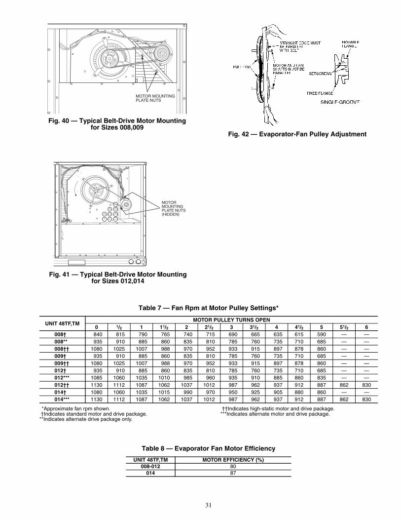
31
Table 7 — Fan Rpm at Motor Pulley Settings*
*Approximate fan rpm shown.†Indicates standard motor and drive package.
**Indicates alternate drive package only.
††Indicates high-static motor and drive package.***Indicates alternate motor and drive package.
Table 8 — Evaporator Fan Motor Efficiency
UNIT 48TF,TMMOTOR PULLEY TURNS OPEN
0 1/2 1 11/2 2 21/2 3 31/2 4 41/2 5 51/2 6008† 840 815 790 765 740 715 690 665 635 615 590 — —008** 935 910 885 860 835 810 785 760 735 710 685 — —008†† 1080 1025 1007 988 970 952 933 915 897 878 860 — —009† 935 910 885 860 835 810 785 760 735 710 685 — —009†† 1080 1025 1007 988 970 952 933 915 897 878 860 — —012† 935 910 885 860 835 810 785 760 735 710 685 — —012*** 1085 1060 1035 1010 985 960 935 910 885 860 835 — —012†† 1130 1112 1087 1062 1037 1012 987 962 937 912 887 862 830014† 1080 1060 1035 1015 990 970 950 925 905 880 860 — —014*** 1130 1112 1087 1062 1037 1012 987 962 937 912 887 862 830
UNIT 48TF,TM MOTOR EFFICIENCY (%)008-012 80
014 87
Fig. 41 — Typical Belt-Drive Motor Mountingfor Sizes 012,014
Fig. 42 — Evaporator-Fan Pulley Adjustment
MOTOR MOUNTINGPLATE NUTS
Fig. 40 — Typical Belt-Drive Motor Mountingfor Sizes 008,009

32
Table 9 — Evaporator-Fan Motor Performance
LEGENDBHP — Brake Horsepower
*Extensive motor and electrical testing on these units ensures thatthe full horsepower range of the motors can be utilized with confi-dence. Using the fan motors up to the horsepower ratings shown inthis table will not result in nuisance tripping or premature motor fail-ure. Unit warranty will not be affected.
NOTE: All indoor-fan motors 5 hp and larger meet the minimum effi-ciency requirements as established by the Energy Policy Act of 1992(EPACT) effective October 24, 1997.
Table 10 — Accessory Static Pressure Drop (in. wg) 48TF,TM008-014
Table 11 — Accessory/FIOP EconoMi$er IV and EconoMi$er2 Static Pressure* (in. wg)
LEGEND *The static pressure must be added to external static pressure. The sum andthe evaporator entering-air cfm should be used in conjunction with the FanPerformance tables to determine indoor blower rpm and watts.
GENERAL NOTES FOR FAN PERFORMANCE DATA TABLES1. Fan Performance is based on clean filters and wet coil data.2. Extensive motor and electrical testing on these units ensures
that the full range of the motor can be utilized with confidence.Using the fan motors up to the wattage ratings shown will notresult in nuisance tripping or premature motor failure. Unitwarranty will not be affected. See Evaporator-Fan Motor Perfor-mance data, Table 9, for additional information.
3. Use of a field-supplied motor may affect wire sizing. Contactyour Carrier representative for details.
4. Interpolation is permissible. Do not extrapolate.
UNIT48TF,TM
EVAPORATOR-FANMOTOR
UNITVOLTAGE
MAXIMUM ACCEPTABLECONTINUOUS BHP*
MAXIMUM ACCEPTABLEOPERATING WATTS
MAXIMUMAMP DRAW
008
Standard,Alternate
208/2302.40 2120
6.7460 3.0575 3.0
High Static208/230
3.70 331312.2
460 5.5575 5.5
009
Standard208/230
2.40 21206.7
460 3.0575 3.0
High Static208/230
3.70 331312.2
460 5.5575 5.5
012
Standard208/230
2.40 21206.7
460 3.0575 3.0
Alternate208/230
2.90 26158.6
460 3.9575 3.9
High Static208/230
5.25 440017.3
460 8.5575 8.5
014
Standard208/230
3.70 331312.2
460 5.5575 5.5
Alternate208/230
5.25 440017.3
460 8.5575 8.5
COMPONENTCFM
900 1200 1400 1600 1800 2000 2200 2400 2600 30001 Heater Module 0.05 0.07 0.09 0.09 0.10 0.11 0.11 0.12 0.13 0.152 Heater Modules 0.15 0.16 0.16 0.16 0.17 0.17 0.17 0.18 0.18 0.19
COMPONENTCFM
1250 1500 1750 2000 2250 2500 2750 3000Vertical Economizer 0.045 0.065 0.08 0.12 0.145 0.175 0.22 0.255Horizontal Economizer — — 0.1 0.125 0.15 0.18 0.225 0.275
FIOP — Factory-Installed Option

33
Table 12 — Fan Performance 48TF008 — Vertical Discharge Units; Standard Motor (Belt Drive)*
LEGEND
*Motor drive range: 590 to 840 rpm. All other rpms require field-supplied drive.
NOTES:1. Boldface indicates field-supplied drive is required.2. Maximum continuous bhp is 2.40.3. See page 32 for General Fan Performance Notes.
AIRFLOW(Cfm)
EXTERNAL STATIC PRESSURE (in. wg)0.2 0.4 0.6 0.8 1.0
Rpm Bhp Watts Rpm Bhp Watts Rpm Bhp Watts Rpm Bhp Watts Rpm Bhp Watts2250 513 0.58 540 593 0.75 702 663 0.94 873 726 1.13 1054 783 1.34 12452300 520 0.61 570 600 0.79 735 669 0.97 908 731 1.17 1092 789 1.38 12852400 535 0.68 633 613 0.86 803 681 1.05 983 743 1.26 1171 799 1.47 13692500 551 0.75 700 627 0.94 877 693 1.14 1062 754 1.35 1256 810 1.56 14592550 559 0.79 736 634 0.98 916 700 1.18 1104 760 1.39 1301 815 1.61 15062600 567 0.83 773 640 1.03 956 706 1.23 1147 766 1.44 1346 821 1.67 15542700 582 0.91 851 655 1.12 1040 719 1.33 1237 778 1.55 1441 832 1.77 16542800 598 1.00 935 669 1.21 1130 732 1.43 1333 790 1.65 1543 844 1.89 17612900 614 1.10 1024 683 1.31 1225 745 1.54 1434 802 1.77 1650 855 2.01 18733000 630 1.20 1119 698 1.42 1327 759 1.65 1542 815 1.89 1763 867 2.14 19923100 647 1.31 1220 713 1.54 1435 773 1.78 1655 828 2.02 1883 879 2.27 21173200 663 1.42 1328 728 1.66 1549 787 1.90 1776 841 2.15 2008 — — —3300 680 1.55 1442 743 1.79 1669 801 2.04 1902 854 2.30 2141 — — —3400 696 1.68 1563 758 1.93 1797 815 2.18 2036 — — — — — —3500 713 1.81 1690 774 2.07 1931 829 2.33 2177 — — — — — —3600 730 1.96 1825 789 2.22 2073 — — — — — — — — —3700 747 2.11 1967 805 2.38 2221 — — — — — — — — —3750 755 2.19 2041 — — — — — — — — — — — —
AIRFLOW(Cfm)
EXTERNAL STATIC PRESSURE (in. wg)1.2 1.4 1.6 1.8 2.0
Rpm Bhp Watts Rpm Bhp Watts Rpm Bhp Watts Rpm Bhp Watts Rpm Bhp Watts2250 837 1.55 1445 887 1.77 1655 934 2.01 1874 979 2.25 2102 — — —2300 842 1.60 1488 891 1.82 1699 938 2.06 1920 983 2.31 2150 — — —2400 852 1.69 1576 901 1.92 1792 948 2.16 2017 — — — — — —2500 862 1.79 1670 911 2.03 1890 957 2.27 2119 — — — — — —2550 867 1.84 1719 916 2.08 1941 962 2.33 2173 — — — — — —2600 872 1.90 1770 921 2.14 1995 966 2.39 2227 — — — — — —2700 883 2.01 1875 931 2.26 2104 — — — — — — — — —2800 894 2.13 1986 — — — — — — — — — — — —2900 — — — — — — — — — — — — — — —3000 — — — — — — — — — — — — — — —3100 — — — — — — — — — — — — — — —3200 — — — — — — — — — — — — — — —3300 — — — — — — — — — — — — — — —3400 — — — — — — — — — — — — — — —3500 — — — — — — — — — — — — — — —3600 — — — — — — — — — — — — — — —3700 — — — — — — — — — — — — — — —3750 — — — — — — — — — — — — — — —
Bhp — Brake Horsepower Input to FanWatts — Input Watts to Motor

34
Table 13 — Fan Performance 48TF008 — Vertical Discharge Units; Alternate Motor (Belt Drive)*
LEGEND
*Motor drive range: 685 to 935 rpm. All other rpms require field-supplied drive.
NOTES:1. Boldface indicates field-supplied drive is required.2. Maximum continuous bhp is 2.40.3. See page 32 for General Fan Performance Notes.
AIRFLOW(Cfm)
EXTERNAL STATIC PRESSURE (in. wg)0.2 0.4 0.6 0.8 1.0
Rpm Bhp Watts Rpm Bhp Watts Rpm Bhp Watts Rpm Bhp Watts Rpm Bhp Watts2250 513 0.58 540 593 0.75 702 663 0.94 873 726 1.13 1054 783 1.34 12452300 520 0.61 570 600 0.79 735 669 0.97 908 731 1.17 1092 789 1.38 12852400 535 0.68 633 613 0.86 803 681 1.05 983 743 1.26 1171 799 1.47 13692500 551 0.75 700 627 0.94 877 693 1.14 1062 754 1.35 1256 810 1.56 14592550 559 0.79 736 634 0.98 916 700 1.18 1104 760 1.39 1301 815 1.61 15062600 567 0.83 773 640 1.03 956 706 1.23 1147 766 1.44 1346 821 1.67 15542700 582 0.91 851 655 1.12 1040 719 1.33 1237 778 1.55 1441 832 1.77 16542800 598 1.00 935 669 1.21 1130 732 1.43 1333 790 1.65 1543 844 1.89 17612900 614 1.10 1024 683 1.31 1225 745 1.54 1434 802 1.77 1650 855 2.01 18733000 630 1.20 1119 698 1.42 1327 759 1.65 1542 815 1.89 1763 867 2.14 19923100 647 1.31 1220 713 1.54 1435 773 1.78 1655 828 2.02 1883 879 2.27 21173200 663 1.42 1328 728 1.66 1549 787 1.90 1776 841 2.15 2008 — — —3300 680 1.55 1442 743 1.79 1669 801 2.04 1902 854 2.30 2141 — — —3400 696 1.68 1563 758 1.93 1797 815 2.18 2036 — — — — — —3500 713 1.81 1690 774 2.07 1931 829 2.33 2177 — — — — — —3600 730 1.96 1825 789 2.22 2073 — — — — — — — — —3700 747 2.11 1967 805 2.38 2221 — — — — — — — — —3750 755 2.19 2041 — — — — — — — — — — — —
AIRFLOW(Cfm)
EXTERNAL STATIC PRESSURE (in. wg)1.2 1.4 1.6 1.8 2.0
Rpm Bhp Watts Rpm Bhp Watts Rpm Bhp Watts Rpm Bhp Watts Rpm Bhp Watts2250 837 1.55 1445 887 1.77 1655 934 2.01 1874 979 2.25 2102 — — —2300 842 1.60 1488 891 1.82 1699 938 2.06 1920 983 2.31 2150 — — —2400 852 1.69 1576 901 1.92 1792 948 2.16 2017 — — — — — —2500 862 1.79 1670 911 2.03 1890 957 2.27 2119 — — — — — —2550 867 1.84 1719 916 2.08 1941 962 2.33 2173 — — — — — —2600 872 1.90 1770 921 2.14 1995 966 2.39 2227 — — — — — —2700 883 2.01 1875 931 2.26 2104 — — — — — — — — —2800 894 2.13 1986 941 2.38 2220 — — — — — — — — —2900 905 2.26 2104 — — — — — — — — — — — —3000 916 2.39 2228 — — — — — — — — — — — —3100 — — — — — — — — — — — — — — —3200 — — — — — — — — — — — — — — —3300 — — — — — — — — — — — — — — —3400 — — — — — — — — — — — — — — —3500 — — — — — — — — — — — — — — —3600 — — — — — — — — — — — — — — —3700 — — — — — — — — — — — — — — —3750 — — — — — — — — — — — — — — —
Bhp — Brake Horsepower Input to FanWatts — Input Watts to Motor

35
Table 14 — Fan Performance 48TF008 — Vertical Discharge Units; High-Static Motor (Belt Drive)*
LEGEND
*Motor drive range: 860 to 1080 rpm. All other rpms require field-supplied drive.
NOTES:1. Boldface indicates field-supplied drive is required.2. Maximum continuous bhp is 3.70.3. See page 32 for General Fan Performance Notes.
AIRFLOW(Cfm)
EXTERNAL STATIC PRESSURE (in. wg)0.2 0.4 0.6 0.8 1.0
Rpm Bhp Watts Rpm Bhp Watts Rpm Bhp Watts Rpm Bhp Watts Rpm Bhp Watts2250 513 0.58 540 593 0.75 702 663 0.94 873 726 1.13 1054 783 1.34 12452300 520 0.61 570 600 0.79 735 669 0.97 908 731 1.17 1092 789 1.38 12852400 535 0.68 633 613 0.86 803 681 1.05 983 743 1.26 1171 799 1.47 13692500 551 0.75 700 627 0.94 877 693 1.14 1062 754 1.35 1256 810 1.56 14592550 559 0.79 736 634 0.98 916 700 1.18 1104 760 1.39 1301 815 1.61 15062600 567 0.83 773 640 1.03 956 706 1.23 1147 766 1.44 1346 821 1.67 15542700 582 0.91 851 655 1.12 1040 719 1.33 1237 778 1.55 1441 832 1.77 16542800 598 1.00 935 669 1.21 1130 732 1.43 1333 790 1.65 1543 844 1.89 17612900 614 1.10 1024 683 1.31 1225 745 1.54 1434 802 1.77 1650 855 2.01 18733000 630 1.20 1119 698 1.42 1327 759 1.65 1542 815 1.89 1763 867 2.14 19923100 647 1.31 1220 713 1.54 1435 773 1.78 1655 828 2.02 1883 879 2.27 21173200 663 1.42 1328 728 1.66 1549 787 1.90 1776 841 2.15 2008 892 2.41 22483300 680 1.55 1442 743 1.79 1669 801 2.04 1902 854 2.30 2141 904 2.56 23863400 696 1.68 1563 758 1.93 1797 815 2.18 2036 868 2.45 2281 917 2.71 25323500 713 1.81 1690 774 2.07 1931 829 2.33 2177 881 2.60 2427 930 2.88 26843600 730 1.96 1825 789 2.22 2073 844 2.49 2324 895 2.77 2581 943 3.05 28433700 747 2.11 1967 805 2.38 2221 859 2.66 2479 909 2.94 2742 956 3.23 30103750 755 2.19 2041 813 2.46 2298 866 2.74 2559 916 3.03 2825 963 3.32 3097
AIRFLOW(Cfm)
EXTERNAL STATIC PRESSURE (in. wg)1.2 1.4 1.6 1.8 2.0
Rpm Bhp Watts Rpm Bhp Watts Rpm Bhp Watts Rpm Bhp Watts Rpm Bhp Watts2250 837 1.55 1445 887 1.77 1655 934 2.01 1874 979 2.25 2102 1022 2.51 23382300 842 1.60 1488 891 1.82 1699 938 2.06 1920 983 2.31 2150 1026 2.56 23872400 852 1.69 1576 901 1.92 1792 948 2.16 2017 992 2.41 2250 1034 2.67 24912500 862 1.79 1670 911 2.03 1890 957 2.27 2119 1001 2.53 2356 1043 2.79 26012550 867 1.84 1719 916 2.08 1941 962 2.33 2173 1005 2.59 2412 1047 2.85 26582600 872 1.90 1770 921 2.14 1995 966 2.39 2227 1010 2.65 2468 1052 2.91 27172700 883 2.01 1875 931 2.26 2104 976 2.51 2342 1019 2.77 2586 1061 3.04 28392800 894 2.13 1986 941 2.38 2220 986 2.64 2462 1029 2.91 2711 1070 3.18 29682900 905 2.26 2104 952 2.51 2343 996 2.78 2588 1039 3.05 2842 1080 3.33 31033000 916 2.39 2228 963 2.65 2471 1007 2.92 2722 1049 3.20 2980 1090 3.48 32453100 928 2.53 2358 974 2.79 2606 1018 3.07 2861 1059 3.35 3124 1100 3.64 33943200 940 2.68 2495 985 2.95 2748 1028 3.23 3008 1070 3.51 3276 — — —3300 952 2.83 2638 997 3.11 2897 1040 3.39 3162 1081 3.68 3434 — — —3400 964 2.99 2789 1008 3.27 3052 1051 3.56 3323 — — — — — —3500 976 3.16 2946 1020 3.45 3216 — — — — — — — — —3600 989 3.34 3112 1032 3.63 3386 — — — — — — — — —3700 1002 3.52 3284 — — — — — — — — — — — —3750 1008 3.62 3374 — — — — — — — — — — — —
Bhp — Brake Horsepower Input to FanWatts — Input Watts to Motor

36
Table 15 — Fan Performance 48TM008 — Vertical Discharge Units; Standard Motor (Belt Drive)*
LEGEND
*Motor drive range: 590 to 840 rpm. All other rpms require field-supplied drive.
NOTES:1. Boldface indicates field-supplied drive is required.2. Maximum continuous bhp is 2.40.3. See page 32 for General Fan Performance Notes.
AIRFLOW(Cfm)
EXTERNAL STATIC PRESSURE (in. wg)0.2 0.4 0.6 0.8 1.0
Rpm Bhp Watts Rpm Bhp Watts Rpm Bhp Watts Rpm Bhp Watts Rpm Bhp Watts2250 513 0.54 505 595 0.76 713 665 1.01 940 728 1.27 1187 786 1.56 14532300 521 0.57 531 601 0.79 741 671 1.04 972 734 1.31 1222 791 1.60 14892400 535 0.63 584 615 0.86 802 684 1.11 1038 745 1.39 1293 802 1.68 15662500 551 0.69 642 628 0.93 866 696 1.19 1109 757 1.47 1369 813 1.77 16472550 558 0.72 673 635 0.97 900 702 1.23 1146 763 1.51 1409 818 1.81 16892600 566 0.76 705 642 1.00 935 709 1.27 1183 769 1.55 1450 824 1.86 17322700 582 0.83 771 656 1.08 1008 721 1.35 1263 781 1.65 1535 835 1.95 18232800 597 0.90 842 670 1.16 1086 734 1.44 1347 793 1.74 1625 847 2.06 19172900 613 0.98 918 684 1.25 1169 748 1.54 1436 805 1.84 1720 859 2.16 20193000 629 1.07 999 699 1.35 1256 761 1.64 1530 818 1.95 1820 871 2.28 21253100 645 1.16 1085 713 1.45 1349 775 1.75 1630 831 2.06 1925 883 2.40 22353200 662 1.26 1176 728 1.55 1448 788 1.86 1734 844 2.18 2036 — — —3300 678 1.36 1272 743 1.66 1551 802 1.98 1845 857 2.31 2152 — — —3400 694 1.47 1374 758 1.78 1660 816 2.10 1961 — — — — — —3500 711 1.59 1482 773 1.90 1775 831 2.23 2082 — — — — — —3600 727 1.71 1596 789 2.03 1896 845 2.37 2210 — — — — — —3700 744 1.84 1716 804 2.17 2023 — — — — — — — — —3750 752 1.91 1778 812 2.24 2089 — — — — — — — — —
AIRFLOW(Cfm)
EXTERNAL STATIC PRESSURE (in. wg)1.2 1.4 1.6 1.8 2.0
Rpm Bhp Watts Rpm Bhp Watts Rpm Bhp Watts Rpm Bhp Watts Rpm Bhp Watts2250 839 1.86 1735 889 2.18 2032 — — — — — — — — —2300 844 1.90 1773 893 2.22 2073 — — — — — — — — —2400 854 1.99 1855 903 2.32 2159 — — — — — — — — —2500 865 2.08 1940 — — — — — — — — — — — —2550 870 2.13 1985 — — — — — — — — — — — —2600 875 2.18 2031 — — — — — — — — — — — —2700 886 2.28 2126 — — — — — — — — — — — —2800 897 2.39 2227 — — — — — — — — — — — —2900 — — — — — — — — — — — — — — —3000 — — — — — — — — — — — — — — —3100 — — — — — — — — — — — — — — —3200 — — — — — — — — — — — — — — —3300 — — — — — — — — — — — — — — —3400 — — — — — — — — — — — — — — —3500 — — — — — — — — — — — — — — —3600 — — — — — — — — — — — — — — —3700 — — — — — — — — — — — — — — —3750 — — — — — — — — — — — — — — —
Bhp — Brake Horsepower Input to FanWatts — Input Watts to Motor

37
Table 16 — Fan Performance 48TM008 — Vertical Discharge Units; Alternate Motor (Belt Drive)*
LEGEND
*Motor drive range: 685 to 935 rpm. All other rpms require field-supplied drive.
NOTES:1. Boldface indicates field-supplied drive is required.2. Maximum continuous bhp is 2.40.3. See page 32 for General Fan Performance Notes.
AIRFLOW(Cfm)
EXTERNAL STATIC PRESSURE (in. wg)0.2 0.4 0.6 0.8 1.0
Rpm Bhp Watts Rpm Bhp Watts Rpm Bhp Watts Rpm Bhp Watts Rpm Bhp Watts2250 513 0.54 505 595 0.76 713 665 1.01 940 728 1.27 1187 786 1.56 14532300 521 0.57 531 601 0.79 741 671 1.04 972 734 1.31 1222 791 1.60 14892400 535 0.63 584 615 0.86 802 684 1.11 1038 745 1.39 1293 802 1.68 15662500 551 0.69 642 628 0.93 866 696 1.19 1109 757 1.47 1369 813 1.77 16472550 558 0.72 673 635 0.97 900 702 1.23 1146 763 1.51 1409 818 1.81 16892600 566 0.76 705 642 1.00 935 709 1.27 1183 769 1.55 1450 824 1.86 17322700 582 0.83 771 656 1.08 1008 721 1.35 1263 781 1.65 1535 835 1.95 18232800 597 0.90 842 670 1.16 1086 734 1.44 1347 793 1.74 1625 847 2.06 19172900 613 0.98 918 684 1.25 1169 748 1.54 1436 805 1.84 1720 859 2.16 20193000 629 1.07 999 699 1.35 1256 761 1.64 1530 818 1.95 1820 871 2.28 21253100 645 1.16 1085 713 1.45 1349 775 1.75 1630 831 2.06 1925 883 2.40 22353200 662 1.26 1176 728 1.55 1448 788 1.86 1734 844 2.18 2036 — — —3300 678 1.36 1272 743 1.66 1551 802 1.98 1845 857 2.31 2152 — — —3400 694 1.47 1374 758 1.78 1660 816 2.10 1961 — — — — — —3500 711 1.59 1482 773 1.90 1775 831 2.23 2082 — — — — — —3600 727 1.71 1596 789 2.03 1896 845 2.37 2210 — — — — — —3700 744 1.84 1716 804 2.17 2023 — — — — — — — — —3750 752 1.91 1778 812 2.24 2089 — — — — — — — — —
AIRFLOW(Cfm)
EXTERNAL STATIC PRESSURE (in. wg)1.2 1.4 1.6 1.8 2.0
Rpm Bhp Watts Rpm Bhp Watts Rpm Bhp Watts Rpm Bhp Watts Rpm Bhp Watts2250 839 1.86 1735 889 2.18 2032 — — — — — — — — —2300 844 1.90 1773 893 2.22 2073 — — — — — — — — —2400 854 1.99 1855 903 2.32 2159 — — — — — — — — —2500 865 2.08 1940 — — — — — — — — — — — —2550 870 2.13 1985 — — — — — — — — — — — —2600 875 2.18 2031 — — — — — — — — — — — —2700 886 2.28 2126 — — — — — — — — — — — —2800 897 2.39 2227 — — — — — — — — — — — —2900 — — — — — — — — — — — — — — —3000 — — — — — — — — — — — — — — —3100 — — — — — — — — — — — — — — —3200 — — — — — — — — — — — — — — —3300 — — — — — — — — — — — — — — —3400 — — — — — — — — — — — — — — —3500 — — — — — — — — — — — — — — —3600 — — — — — — — — — — — — — — —3700 — — — — — — — — — — — — — — —3750 — — — — — — — — — — — — — — —
Bhp — Brake Horsepower Input to FanWatts — Input Watts to Motor

38
Table 17 — Fan Performance 48TM008 — Vertical Discharge Units; High-Static Motor (Belt Drive)*
LEGEND
*Motor drive range: 860 to 1080 rpm. All other rpms require field-supplied drive.
NOTES:1. Boldface indicates field-supplied drive is required.2. Maximum continuous bhp is 3.70.3. See page 32 for General Fan Performance Notes.
AIRFLOW(Cfm)
EXTERNAL STATIC PRESSURE (in. wg)0.2 0.4 0.6 0.8 1.0
Rpm Bhp Watts Rpm Bhp Watts Rpm Bhp Watts Rpm Bhp Watts Rpm Bhp Watts2250 513 0.54 505 595 0.76 713 665 1.01 940 728 1.27 1187 786 1.56 14532300 521 0.57 531 601 0.79 741 671 1.04 972 734 1.31 1222 791 1.60 14892400 535 0.63 584 615 0.86 802 684 1.11 1038 745 1.39 1293 802 1.68 15662500 551 0.69 642 628 0.93 866 696 1.19 1109 757 1.47 1369 813 1.77 16472550 558 0.72 673 635 0.97 900 702 1.23 1146 763 1.51 1409 818 1.81 16892600 566 0.76 705 642 1.00 935 709 1.27 1183 769 1.55 1450 824 1.86 17322700 582 0.83 771 656 1.08 1008 721 1.35 1263 781 1.65 1535 835 1.95 18232800 597 0.90 842 670 1.16 1086 734 1.44 1347 793 1.74 1625 847 2.06 19172900 613 0.98 918 684 1.25 1169 748 1.54 1436 805 1.84 1720 859 2.16 20193000 629 1.07 999 699 1.35 1256 761 1.64 1530 818 1.95 1820 871 2.28 21253100 645 1.16 1085 713 1.45 1349 775 1.75 1630 831 2.06 1925 883 2.40 22353200 662 1.26 1176 728 1.55 1448 788 1.86 1734 844 2.18 2036 895 2.52 23523300 678 1.36 1272 743 1.66 1551 802 1.98 1845 857 2.31 2152 908 2.65 24753400 694 1.47 1374 758 1.78 1660 816 2.10 1961 870 2.44 2275 920 2.79 26033500 711 1.59 1482 773 1.90 1775 831 2.23 2082 884 2.58 2402 933 2.93 27373600 727 1.71 1596 789 2.03 1896 845 2.37 2210 897 2.72 2537 946 3.09 28773700 744 1.84 1716 804 2.17 2023 860 2.51 2343 911 2.87 2677 959 3.24 30233750 752 1.91 1778 812 2.24 2089 867 2.59 2413 918 2.95 2750 966 3.32 3100
AIRFLOW(Cfm)
EXTERNAL STATIC PRESSURE (in. wg)1.2 1.4 1.6 1.8 2.0
Rpm Bhp Watts Rpm Bhp Watts Rpm Bhp Watts Rpm Bhp Watts Rpm Bhp Watts2250 839 1.86 1735 889 2.18 2032 935 2.52 2345 980 2.87 2673 1022 3.23 30152300 844 1.90 1773 893 2.22 2073 940 2.56 2389 984 2.91 2718 1027 3.28 30622400 854 1.99 1855 903 2.32 2159 950 2.66 2478 993 3.02 2812 1035 3.39 31592500 865 2.08 1940 913 2.41 2249 959 2.76 2573 1003 3.12 2911 1044 3.50 32612550 870 2.13 1985 918 2.46 2296 964 2.81 2622 1008 3.18 2962 1049 3.55 33152600 875 2.18 2031 923 2.51 2344 969 2.87 2673 1012 3.23 3014 1054 3.61 33702700 886 2.28 2126 934 2.62 2445 979 2.98 2777 1022 3.35 3123 — — —2800 897 2.39 2227 944 2.73 2550 989 3.10 2888 1032 3.47 3238 — — —2900 908 2.50 2333 955 2.85 2661 1000 3.22 3003 1042 3.60 3358 — — —3000 920 2.62 2443 966 2.98 2777 1010 3.35 3123 — — — — — —3100 931 2.75 2560 977 3.11 2899 1021 3.49 3250 — — — — — —3200 943 2.88 2682 989 3.25 3026 1032 3.63 3383 — — — — — —3300 955 3.01 2810 1000 3.39 3159 — — — — — — — — —3400 967 3.16 2945 1012 3.54 3299 — — — — — — — — —3500 980 3.31 3084 1024 3.69 3445 — — — — — — — — —3600 992 3.46 3230 — — — — — — — — — — — —3700 1005 3.63 3383 — — — — — — — — — — — —3750 — — — — — — — — — — — — — — —
Bhp — Brake Horsepower Input to FanWatts — Input Watts to Motor

39
Table 18 — Fan Performance 48TF009 — Vertical Discharge Units; Standard Motor (Belt Drive)*
LEGEND
*Motor drive range: 685 to 935 rpm. All other rpms require field-supplied drive.
NOTES:1. Boldface indicates field-supplied drive is required.2. Maximum continuous bhp is 2.40.3. See page 32 for General Fan Performance Notes.
AIRFLOW(Cfm)
EXTERNAL STATIC PRESSURE (in. wg)0.2 0.4 0.6 0.8 1.0
Rpm Bhp Watts Rpm Bhp Watts Rpm Bhp Watts Rpm Bhp Watts Rpm Bhp Watts2550 559 0.79 736 634 0.98 916 700 1.18 1104 760 1.39 1301 815 1.61 15062600 567 0.83 773 640 1.03 956 706 1.23 1147 766 1.44 1346 821 1.67 15542700 582 0.91 851 655 1.12 1040 719 1.33 1237 778 1.55 1441 832 1.77 16542800 598 1.00 935 669 1.21 1130 732 1.43 1333 790 1.65 1543 844 1.89 17612900 614 1.10 1024 683 1.31 1225 745 1.54 1434 802 1.77 1650 855 2.01 18733000 630 1.20 1119 698 1.42 1327 759 1.65 1542 815 1.89 1763 867 2.14 19923100 647 1.31 1220 713 1.54 1435 773 1.78 1655 828 2.02 1883 879 2.27 21173200 663 1.42 1328 728 1.66 1549 787 1.90 1776 841 2.15 2008 — — —3300 680 1.55 1442 743 1.79 1669 801 2.04 1902 854 2.30 2141 — — —3400 696 1.68 1563 758 1.93 1797 815 2.18 2036 — — — — — —3500 713 1.81 1690 774 2.07 1931 829 2.33 2177 — — — — — —3600 730 1.96 1825 789 2.22 2073 — — — — — — — — —3700 747 2.11 1967 805 2.38 2221 — — — — — — — — —3750 755 2.19 2041 — — — — — — — — — — — —3800 764 2.27 2117 — — — — — — — — — — — —3900 — — — — — — — — — — — — — — —4000 — — — — — — — — — — — — — — —4100 — — — — — — — — — — — — — — —4200 — — — — — — — — — — — — — — —4250 — — — — — — — — — — — — — — —
AIRFLOW(Cfm)
EXTERNAL STATIC PRESSURE (in. wg)1.2 1.4 1.6 1.8 2.0
Rpm Bhp Watts Rpm Bhp Watts Rpm Bhp Watts Rpm Bhp Watts Rpm Bhp Watts2550 867 1.84 1719 916 2.08 1941 962 2.33 2173 — — — — — —2600 872 1.90 1770 921 2.14 1995 966 2.39 2227 — — — — — —2700 883 2.01 1875 931 2.26 2104 — — — — — — — — —2800 894 2.13 1986 941 2.38 2220 — — — — — — — — —2900 905 2.26 2104 — — — — — — — — — — — —3000 916 2.39 2228 — — — — — — — — — — — —3100 — — — — — — — — — — — — — — —3200 — — — — — — — — — — — — — — —3300 — — — — — — — — — — — — — — —3400 — — — — — — — — — — — — — — —3500 — — — — — — — — — — — — — — —3600 — — — — — — — — — — — — — — —3700 — — — — — — — — — — — — — — —3750 — — — — — — — — — — — — — — —3800 — — — — — — — — — — — — — — —3900 — — — — — — — — — — — — — — —4000 — — — — — — — — — — — — — — —4100 — — — — — — — — — — — — — — —4200 — — — — — — — — — — — — — — —4250 — — — — — — — — — — — — — — —
Bhp — Brake Horsepower Input to FanWatts — Input Watts to Motor

40
Table 19 — Fan Performance 48TF009 — Vertical Discharge Units; High-Static Motor (Belt Drive)*
LEGEND
*Motor drive range: 860 to 1080 rpm. All other rpms require field-supplied drive.
NOTES:1. Boldface indicates field-supplied drive is required.2. Maximum continuous bhp is 3.70.3. See page 32 for General Fan Performance Notes.
AIRFLOW(Cfm)
EXTERNAL STATIC PRESSURE (in. wg)0.2 0.4 0.6 0.8 1.0
Rpm Bhp Watts Rpm Bhp Watts Rpm Bhp Watts Rpm Bhp Watts Rpm Bhp Watts2550 559 0.79 736 634 0.98 916 700 1.18 1104 760 1.39 1301 815 1.61 15062600 567 0.83 773 640 1.03 956 706 1.23 1147 766 1.44 1346 821 1.67 15542700 582 0.91 851 655 1.12 1040 719 1.33 1237 778 1.55 1441 832 1.77 16542800 598 1.00 935 669 1.21 1130 732 1.43 1333 790 1.65 1543 844 1.89 17612900 614 1.10 1024 683 1.31 1225 745 1.54 1434 802 1.77 1650 855 2.01 18733000 630 1.20 1119 698 1.42 1327 759 1.65 1542 815 1.89 1763 867 2.14 19923100 647 1.31 1220 713 1.54 1435 773 1.78 1655 828 2.02 1883 879 2.27 21173200 663 1.42 1328 728 1.66 1549 787 1.90 1776 841 2.15 2008 892 2.41 22483300 680 1.55 1442 743 1.79 1669 801 2.04 1902 854 2.30 2141 904 2.56 23863400 696 1.68 1563 758 1.93 1797 815 2.18 2036 868 2.45 2281 917 2.71 25323500 713 1.81 1690 774 2.07 1931 829 2.33 2177 881 2.60 2427 930 2.88 26843600 730 1.96 1825 789 2.22 2073 844 2.49 2324 895 2.77 2581 943 3.05 28433700 747 2.11 1967 805 2.38 2221 859 2.66 2479 909 2.94 2742 956 3.23 30103750 755 2.19 2041 813 2.46 2298 866 2.74 2559 916 3.03 2825 963 3.32 30973800 764 2.27 2117 821 2.55 2377 873 2.83 2642 923 3.12 2911 970 3.42 31853900 781 2.44 2274 836 2.73 2541 888 3.02 2812 937 3.31 3087 983 3.61 33674000 798 2.62 2440 852 2.91 2713 904 3.21 2991 952 3.51 3272 — — —4100 815 2.80 2613 868 3.10 2893 919 3.41 3177 — — — — — —4200 832 3.00 2795 885 3.30 3082 934 3.62 3372 — — — — — —4250 841 3.10 2889 893 3.41 3179 — — — — — — — — —
AIRFLOW(Cfm)
EXTERNAL STATIC PRESSURE (in. wg)1.2 1.4 1.6 1.8 2.0
Rpm Bhp Watts Rpm Bhp Watts Rpm Bhp Watts Rpm Bhp Watts Rpm Bhp Watts2550 867 1.84 1719 916 2.08 1941 962 2.33 2173 1005 2.59 2412 1047 2.85 26582600 872 1.90 1770 921 2.14 1995 966 2.39 2227 1010 2.65 2468 1052 2.91 27172700 883 2.01 1875 931 2.26 2104 976 2.51 2342 1019 2.77 2586 1061 3.04 28392800 894 2.13 1986 941 2.38 2220 986 2.64 2462 1029 2.91 2711 1070 3.18 29682900 905 2.26 2104 952 2.51 2343 996 2.78 2588 1039 3.05 2842 1080 3.33 31033000 916 2.39 2228 963 2.65 2471 1007 2.92 2722 1049 3.20 2980 1090 3.48 32453100 928 2.53 2358 974 2.79 2606 1018 3.07 2861 1059 3.35 3124 1100 3.64 33943200 940 2.68 2495 985 2.95 2748 1028 3.23 3008 1070 3.51 3276 — — —3300 952 2.83 2638 997 3.11 2897 1040 3.39 3162 1081 3.68 3434 — — —3400 964 2.99 2789 1008 3.27 3052 1051 3.56 3323 — — — — — —3500 976 3.16 2946 1020 3.45 3216 — — — — — — — — —3600 989 3.34 3112 1032 3.63 3386 — — — — — — — — —3700 1002 3.52 3284 — — — — — — — — — — — —3750 1008 3.62 3374 — — — — — — — — — — — —3800 — — — — — — — — — — — — — — —3900 — — — — — — — — — — — — — — —4000 — — — — — — — — — — — — — — —4100 — — — — — — — — — — — — — — —4200 — — — — — — — — — — — — — — —4250 — — — — — — — — — — — — — — —
Bhp — Brake Horsepower Input to FanWatts — Input Watts to Motor

41
Table 20 — Fan Performance 48TM009 — Vertical Discharge Units; Standard Motor (Belt Drive)*
LEGEND
*Motor drive range: 685 to 935 rpm. All other rpms require field-supplied drive.
NOTES:1. Boldface indicates field-supplied drive is required.2. Maximum continuous bhp is 2.40.3. See page 32 for General Fan Performance Notes.
AIRFLOW(Cfm)
EXTERNAL STATIC PRESSURE (in. wg)0.2 0.4 0.6 0.8 1.0
Rpm Bhp Watts Rpm Bhp Watts Rpm Bhp Watts Rpm Bhp Watts Rpm Bhp Watts2550 558 0.72 673 635 0.97 900 702 1.23 1146 763 1.51 1409 818 1.81 16892600 566 0.76 705 642 1.00 935 709 1.27 1183 769 1.55 1450 824 1.86 17322700 582 0.83 771 656 1.08 1008 721 1.35 1263 781 1.65 1535 835 1.95 18232800 597 0.90 842 670 1.16 1086 734 1.44 1347 793 1.74 1625 847 2.06 19172900 613 0.98 918 684 1.25 1169 748 1.54 1436 805 1.84 1720 859 2.16 20193000 629 1.07 999 699 1.35 1256 761 1.64 1530 818 1.95 1820 871 2.28 21253100 645 1.16 1085 713 1.45 1349 775 1.75 1630 831 2.06 1925 883 2.40 22353200 662 1.26 1176 728 1.55 1448 788 1.86 1734 844 2.18 2036 — — —3300 678 1.36 1272 743 1.66 1551 802 1.98 1845 857 2.31 2152 — — —3400 694 1.47 1374 758 1.78 1660 816 2.10 1961 — — — — — —3500 711 1.59 1482 773 1.90 1775 831 2.23 2082 — — — — — —3600 727 1.71 1596 789 2.03 1896 845 2.37 2210 — — — — — —3700 744 1.84 1716 804 2.17 2023 — — — — — — — — —3750 752 1.91 1778 812 2.24 2089 — — — — — — — — —3800 761 1.98 1842 820 2.31 2156 — — — — — — — — —3900 777 2.12 1974 — — — — — — — — — — — —4000 794 2.27 2113 — — — — — — — — — — — —4100 — — — — — — — — — — — — — — —4200 — — — — — — — — — — — — — — —4250 — — — — — — — — — — — — — — —
AIRFLOW(Cfm)
EXTERNAL STATIC PRESSURE (in. wg)1.2 1.4 1.6 1.8 2.0
Rpm Bhp Watts Rpm Bhp Watts Rpm Bhp Watts Rpm Bhp Watts Rpm Bhp Watts2550 870 2.13 1985 — — — — — — — — — — — —2600 875 2.18 2031 — — — — — — — — — — — —2700 886 2.28 2126 — — — — — — — — — — — —2800 897 2.39 2227 — — — — — — — — — — — —2900 — — — — — — — — — — — — — — —3000 — — — — — — — — — — — — — — —3100 — — — — — — — — — — — — — — —3200 — — — — — — — — — — — — — — —3300 — — — — — — — — — — — — — — —3400 — — — — — — — — — — — — — — —3500 — — — — — — — — — — — — — — —3600 — — — — — — — — — — — — — — —3700 — — — — — — — — — — — — — — —3750 — — — — — — — — — — — — — — —3800 — — — — — — — — — — — — — — —3900 — — — — — — — — — — — — — — —4000 — — — — — — — — — — — — — — —4100 — — — — — — — — — — — — — — —4200 — — — — — — — — — — — — — — —4250 — — — — — — — — — — — — — — —
Bhp — Brake Horsepower Input to FanWatts — Input Watts to Motor

42
Table 21 — Fan Performance 48TM009 — Vertical Discharge Units; High-Static Motor (Belt Drive)*
LEGEND
*Motor drive range: 860 to 1080 rpm. All other rpms require field-supplied drive.
NOTES:1. Boldface indicates field-supplied drive is required.2. Maximum continuous bhp is 3.70.3. See page 32 for General Fan Performance Notes.
AIRFLOW(Cfm)
EXTERNAL STATIC PRESSURE (in. wg)0.2 0.4 0.6 0.8 1.0
Rpm Bhp Watts Rpm Bhp Watts Rpm Bhp Watts Rpm Bhp Watts Rpm Bhp Watts2550 558 0.72 673 635 0.97 900 702 1.23 1146 763 1.51 1409 818 1.81 16892600 566 0.76 705 642 1.00 935 709 1.27 1183 769 1.55 1450 824 1.86 17322700 582 0.83 771 656 1.08 1008 721 1.35 1263 781 1.65 1535 835 1.95 18232800 597 0.90 842 670 1.16 1086 734 1.44 1347 793 1.74 1625 847 2.06 19172900 613 0.98 918 684 1.25 1169 748 1.54 1436 805 1.84 1720 859 2.16 20193000 629 1.07 999 699 1.35 1256 761 1.64 1530 818 1.95 1820 871 2.28 21253100 645 1.16 1085 713 1.45 1349 775 1.75 1630 831 2.06 1925 883 2.40 22353200 662 1.26 1176 728 1.55 1448 788 1.86 1734 844 2.18 2036 895 2.52 23523300 678 1.36 1272 743 1.66 1551 802 1.98 1845 857 2.31 2152 908 2.65 24753400 694 1.47 1374 758 1.78 1660 816 2.10 1961 870 2.44 2275 920 2.79 26033500 711 1.59 1482 773 1.90 1775 831 2.23 2082 884 2.58 2402 933 2.93 27373600 727 1.71 1596 789 2.03 1896 845 2.37 2210 897 2.72 2537 946 3.09 28773700 744 1.84 1716 804 2.17 2023 860 2.51 2343 911 2.87 2677 959 3.24 30233750 752 1.91 1778 812 2.24 2089 867 2.59 2413 918 2.95 2750 966 3.32 31003800 761 1.98 1842 820 2.31 2156 874 2.66 2484 925 3.03 2824 973 3.41 31773900 777 2.12 1974 835 2.46 2296 889 2.82 2630 939 3.19 2977 986 3.58 33364000 794 2.27 2113 851 2.62 2442 904 2.99 2784 953 3.36 3137 — — —4100 811 2.42 2259 867 2.78 2595 919 3.16 2944 968 3.54 3304 — — —4200 828 2.59 2412 883 2.95 2755 934 3.34 3110 — — — — — —4250 837 2.67 2490 891 3.04 2838 942 3.43 3197 — — — — — —
AIRFLOW(Cfm)
EXTERNAL STATIC PRESSURE (in. wg)1.2 1.4 1.6 1.8 2.0
Rpm Bhp Watts Rpm Bhp Watts Rpm Bhp Watts Rpm Bhp Watts Rpm Bhp Watts2550 870 2.13 1985 918 2.46 2296 964 2.81 2622 1008 3.18 2962 1049 3.55 33152600 875 2.18 2031 923 2.51 2344 969 2.87 2673 1012 3.23 3014 1054 3.61 33702700 886 2.28 2126 934 2.62 2445 979 2.98 2777 1022 3.35 3123 — — —2800 897 2.39 2227 944 2.73 2550 989 3.10 2888 1032 3.47 3238 — — —2900 908 2.50 2333 955 2.85 2661 1000 3.22 3003 1042 3.60 3358 — — —3000 920 2.62 2443 966 2.98 2777 1010 3.35 3123 — — — — — —3100 931 2.75 2560 977 3.11 2899 1021 3.49 3250 — — — — — —3200 943 2.88 2682 989 3.25 3026 1032 3.63 3383 — — — — — —3300 955 3.01 2810 1000 3.39 3159 — — — — — — — — —3400 967 3.16 2945 1012 3.54 3299 — — — — — — — — —3500 980 3.31 3084 1024 3.69 3445 — — — — — — — — —3600 992 3.46 3230 — — — — — — — — — — — —3700 1005 3.63 3383 — — — — — — — — — — — —3750 — — — — — — — — — — — — — — —3800 — — — — — — — — — — — — — — —3900 — — — — — — — — — — — — — — —4000 — — — — — — — — — — — — — — —4100 — — — — — — — — — — — — — — —4200 — — — — — — — — — — — — — — —4250 — — — — — — — — — — — — — — —
Bhp — Brake Horsepower Input to FanWatts — Input Watts to Motor

43
Table 22 — Fan Performance 48TF,TM012 — Vertical Discharge Units; Standard Motor (Belt Drive)*
LEGEND
*Motor drive range: 685 to 935 rpm. All other rpms require field-supplied drive.
NOTES:1. Boldface indicates field-supplied drive is required.2. Maximum continuous bhp is 2.40.3. See page 32 for General Fan Performance Notes.
AIRFLOW(Cfm)
EXTERNAL STATIC PRESSURE (in. wg)0.2 0.4 0.6 0.8 1.0
Rpm Bhp Watts Rpm Bhp Watts Rpm Bhp Watts Rpm Bhp Watts Rpm Bhp Watts3000 555 0.72 630 629 0.87 765 696 1.03 904 757 1.19 1048 814 1.36 11983100 568 0.78 686 641 0.94 825 706 1.10 968 766 1.27 1115 823 1.45 12693200 582 0.85 745 652 1.01 888 717 1.18 1035 776 1.35 1186 832 1.53 13433300 595 0.92 808 664 1.09 955 728 1.26 1106 786 1.44 1261 841 1.62 14213400 609 1.00 874 677 1.17 1026 739 1.35 1181 797 1.53 1340 851 1.71 15033500 623 1.08 945 689 1.25 1100 750 1.43 1259 807 1.62 1422 860 1.81 15893600 636 1.16 1019 702 1.34 1179 762 1.53 1341 817 1.72 1508 870 1.91 16793700 650 1.25 1097 714 1.44 1261 773 1.63 1428 828 1.82 1598 880 2.02 17723800 664 1.34 1179 727 1.54 1347 785 1.73 1518 839 1.93 1693 890 2.13 18703900 678 1.44 1266 740 1.64 1438 797 1.84 1613 850 2.04 1791 901 2.25 19734000 693 1.55 1356 753 1.75 1533 809 1.95 1712 861 2.16 1894 911 2.37 20804100 707 1.65 1451 766 1.86 1632 821 2.07 1816 873 2.28 2002 — — —4200 721 1.77 1551 779 1.98 1736 833 2.19 1924 — — — — — —4300 735 1.89 1656 792 2.10 1845 846 2.32 2037 — — — — — —4400 750 2.01 1764 806 2.23 1958 — — — — — — — — —4500 764 2.14 1879 819 2.37 2077 — — — — — — — — —4600 779 2.28 1998 — — — — — — — — — — — —4700 — — — — — — — — — — — — — — —4800 — — — — — — — — — — — — — — —4900 — — — — — — — — — — — — — — —5000 — — — — — — — — — — — — — — —
AIRFLOW(Cfm)
EXTERNAL STATIC PRESSURE (in. wg)1.2 1.4 1.6 1.8 2.0
Rpm Bhp Watts Rpm Bhp Watts Rpm Bhp Watts Rpm Bhp Watts Rpm Bhp Watts3000 867 1.54 1353 918 1.72 1513 966 1.91 1680 1012 2.11 1852 1056 2.31 20293100 876 1.63 1427 926 1.81 1590 973 2.00 1760 1019 2.20 1934 — — —3200 884 1.71 1504 934 1.90 1671 981 2.10 1843 1026 2.30 2020 — — —3300 893 1.81 1586 942 2.00 1755 988 2.20 1931 1033 2.40 2111 — — —3400 902 1.90 1671 950 2.10 1844 996 2.30 2022 — — — — — —3500 911 2.01 1760 959 2.21 1937 — — — — — — — — —3600 920 2.11 1854 967 2.32 2033 — — — — — — — — —3700 929 2.22 1951 — — — — — — — — — — — —3800 939 2.34 2053 — — — — — — — — — — — —3900 — — — — — — — — — — — — — — —4000 — — — — — — — — — — — — — — —4100 — — — — — — — — — — — — — — —4200 — — — — — — — — — — — — — — —4300 — — — — — — — — — — — — — — —4400 — — — — — — — — — — — — — — —4500 — — — — — — — — — — — — — — —4600 — — — — — — — — — — — — — — —4700 — — — — — — — — — — — — — — —4800 — — — — — — — — — — — — — — —4900 — — — — — — — — — — — — — — —5000 — — — — — — — — — — — — — — —
Bhp — Brake Horsepower Input to FanWatts — Input Watts to Motor

44
Table 23 — Fan Performance 48TF,TM012 — Vertical Discharge Units; Alternate Motor (Belt Drive)*
LEGEND
*Motor drive range: 835 to 1085 rpm. All other rpms require field-supplied drive.
NOTES:1. Boldface indicates field-supplied drive is required.2. Maximum continuous bhp is 2.90.3. See page 32 for General Fan Performance Notes.
AIRFLOW(Cfm)
EXTERNAL STATIC PRESSURE (in. wg)0.2 0.4 0.6 0.8 1.0
Rpm Bhp Watts Rpm Bhp Watts Rpm Bhp Watts Rpm Bhp Watts Rpm Bhp Watts3000 592 0.77 672 658 0.93 817 719 1.10 961 775 1.26 1105 828 1.42 12493100 607 0.83 731 672 1.00 881 731 1.17 1030 787 1.34 1179 839 1.51 13283200 623 0.90 794 686 1.08 949 744 1.26 1103 798 1.43 1257 850 1.61 14103300 638 0.98 860 700 1.16 1020 757 1.34 1179 810 1.52 1338 861 1.71 14963400 653 1.06 931 714 1.25 1095 770 1.44 1260 822 1.62 1423 872 1.81 15863500 669 1.15 1005 728 1.34 1175 783 1.53 1344 835 1.72 1512 884 1.91 16803600 685 1.23 1084 742 1.43 1258 796 1.63 1432 847 1.83 1606 895 2.03 17783700 700 1.33 1167 757 1.53 1346 810 1.74 1524 860 1.94 1703 907 2.14 18813800 716 1.43 1254 771 1.64 1438 823 1.85 1621 873 2.06 1805 919 2.26 19873900 732 1.53 1345 786 1.75 1534 837 1.96 1722 886 2.18 1911 932 2.39 20994000 748 1.64 1441 801 1.86 1635 851 2.08 1828 899 2.30 2022 944 2.52 22144100 764 1.76 1542 816 1.98 1741 865 2.21 1939 912 2.43 2137 957 2.66 23344200 780 1.88 1648 831 2.11 1851 879 2.34 2054 925 2.57 2257 969 2.80 24604300 796 2.00 1758 846 2.24 1966 894 2.48 2175 939 2.71 2382 — — —4400 812 2.13 1874 861 2.38 2087 908 2.62 2299 952 2.86 2512 — — —4500 828 2.27 1994 877 2.52 2212 922 2.77 2430 — — — — — —4600 845 2.42 2120 892 2.67 2343 — — — — — — — — —4700 861 2.57 2251 907 2.82 2479 — — — — — — — — —4800 877 2.72 2388 — — — — — — — — — — — —4900 894 2.88 2531 — — — — — — — — — — — —5000 — — — — — — — — — — — — — — —
AIRFLOW(Cfm)
EXTERNAL STATIC PRESSURE (in. wg)1.2 1.4 1.6 1.8 2.0
Rpm Bhp Watts Rpm Bhp Watts Rpm Bhp Watts Rpm Bhp Watts Rpm Bhp Watts3000 878 1.59 1391 925 1.75 1534 970 1.91 1676 1014 2.07 1817 1055 2.23 19583100 888 1.68 1475 935 1.85 1623 979 2.02 1769 1022 2.18 1916 1063 2.35 20623200 898 1.78 1563 944 1.95 1715 988 2.13 1867 1031 2.30 2018 1072 2.47 21693300 909 1.88 1654 954 2.06 1811 998 2.24 1968 1040 2.42 2124 1080 2.60 22803400 919 1.99 1749 964 2.18 1911 1007 2.36 2073 1049 2.55 2234 1089 2.73 23953500 930 2.11 1848 975 2.30 2015 1017 2.49 2182 1058 2.68 2348 1098 2.86 25143600 941 2.22 1951 985 2.42 2123 1027 2.61 2295 1068 2.81 2466 — — —3700 952 2.35 2058 996 2.55 2236 1038 2.75 2412 — — — — — —3800 964 2.47 2170 1007 2.68 2352 1048 2.89 2534 — — — — — —3900 976 2.60 2286 1018 2.82 2473 — — — — — — — — —4000 987 2.74 2407 — — — — — — — — — — — —4100 999 2.88 2532 — — — — — — — — — — — —4200 — — — — — — — — — — — — — — —4300 — — — — — — — — — — — — — — —4400 — — — — — — — — — — — — — — —4500 — — — — — — — — — — — — — — —4600 — — — — — — — — — — — — — — —4700 — — — — — — — — — — — — — — —4800 — — — — — — — — — — — — — — —4900 — — — — — — — — — — — — — — —5000 — — — — — — — — — — — — — — —
Bhp — Brake Horsepower Input to FanWatts — Input Watts to Motor

45
Table 24 — Fan Performance 48TF,TM012 — Vertical Discharge Units; High-Static Motor (Belt Drive)*
LEGEND
*Motor drive range: 830 to 1130 rpm. All other rpms require field-supplied drive.
NOTES:1. Boldface indicates field-supplied drive is required.2. Maximum continuous bhp is 5.25.3. See page 32 for General Fan Performance Notes.
AIRFLOW(Cfm)
EXTERNAL STATIC PRESSURE (in. wg)0.2 0.4 0.6 0.8 1.0
Rpm Bhp Watts Rpm Bhp Watts Rpm Bhp Watts Rpm Bhp Watts Rpm Bhp Watts3000 592 0.77 672 658 0.93 817 719 1.10 961 775 1.26 1105 828 1.42 12493100 607 0.83 731 672 1.00 881 731 1.17 1030 787 1.34 1179 839 1.51 13283200 623 0.90 794 686 1.08 949 744 1.26 1103 798 1.43 1257 850 1.61 14103300 638 0.98 860 700 1.16 1020 757 1.34 1179 810 1.52 1338 861 1.71 14963400 653 1.06 931 714 1.25 1095 770 1.44 1260 822 1.62 1423 872 1.81 15863500 669 1.15 1005 728 1.34 1175 783 1.53 1344 835 1.72 1512 884 1.91 16803600 685 1.23 1084 742 1.43 1258 796 1.63 1432 847 1.83 1606 895 2.03 17783700 700 1.33 1167 757 1.53 1346 810 1.74 1524 860 1.94 1703 907 2.14 18813800 716 1.43 1254 771 1.64 1438 823 1.85 1621 873 2.06 1805 919 2.26 19873900 732 1.53 1345 786 1.75 1534 837 1.96 1722 886 2.18 1911 932 2.39 20994000 748 1.64 1441 801 1.86 1635 851 2.08 1828 899 2.30 2022 944 2.52 22144100 764 1.76 1542 816 1.98 1741 865 2.21 1939 912 2.43 2137 957 2.66 23344200 780 1.88 1648 831 2.11 1851 879 2.34 2054 925 2.57 2257 969 2.80 24604300 796 2.00 1758 846 2.24 1966 894 2.48 2175 939 2.71 2382 982 2.95 25894400 812 2.13 1874 861 2.38 2087 908 2.62 2299 952 2.86 2512 995 3.10 27254500 828 2.27 1994 877 2.52 2212 922 2.77 2430 966 3.02 2648 1008 3.26 28654600 845 2.42 2120 892 2.67 2343 937 2.92 2566 980 3.18 2788 1022 3.43 30104700 861 2.57 2251 907 2.82 2479 952 3.08 2706 994 3.34 2934 1035 3.60 31614800 877 2.72 2388 923 2.99 2621 966 3.25 2853 1008 3.52 3086 1049 3.78 33174900 894 2.88 2531 938 3.15 2768 981 3.42 3005 1022 3.69 3242 1062 3.96 34795000 910 3.05 2679 954 3.33 2921 996 3.60 3163 1037 3.88 3405 1076 4.15 3647
AIRFLOW(Cfm)
EXTERNAL STATIC PRESSURE (in. wg)1.2 1.4 1.6 1.8 2.0
Rpm Bhp Watts Rpm Bhp Watts Rpm Bhp Watts Rpm Bhp Watts Rpm Bhp Watts3000 878 1.59 1391 925 1.75 1534 970 1.91 1676 1014 2.07 1817 1055 2.23 19583100 888 1.68 1475 935 1.85 1623 979 2.02 1769 1022 2.18 1916 1063 2.35 20623200 898 1.78 1563 944 1.95 1715 988 2.13 1867 1031 2.30 2018 1072 2.47 21693300 909 1.88 1654 954 2.06 1811 998 2.24 1968 1040 2.42 2124 1080 2.60 22803400 919 1.99 1749 964 2.18 1911 1007 2.36 2073 1049 2.55 2234 1089 2.73 23953500 930 2.11 1848 975 2.30 2015 1017 2.49 2182 1058 2.68 2348 1098 2.86 25143600 941 2.22 1951 985 2.42 2123 1027 2.61 2295 1068 2.81 2466 1107 3.00 26373700 952 2.35 2058 996 2.55 2236 1038 2.75 2412 1078 2.95 2588 1117 3.15 27643800 964 2.47 2170 1007 2.68 2352 1048 2.89 2534 1088 3.09 2715 1126 3.30 28953900 976 2.60 2286 1018 2.82 2473 1059 3.03 2660 1098 3.24 2846 1136 3.45 30314000 987 2.74 2407 1029 2.96 2598 1069 3.18 2790 1108 3.40 2981 1146 3.61 31714100 999 2.88 2532 1041 3.11 2729 1080 3.33 2925 1119 3.56 3121 1156 3.78 33164200 1012 3.03 2662 1052 3.26 2863 1092 3.49 3065 1130 3.72 3266 1167 3.95 34664300 1024 3.19 2796 1064 3.42 3003 1103 3.66 3210 1141 3.89 3415 1177 4.13 36214400 1036 3.35 2937 1076 3.59 3148 1114 3.83 3359 1152 4.07 3570 1188 4.31 37814500 1049 3.51 3082 1088 3.76 3298 1126 4.00 3514 1163 4.25 3730 1199 4.50 39454600 1062 3.68 3232 1100 3.94 3454 1138 4.19 3675 1174 4.44 3895 1210 4.69 41164700 1075 3.86 3387 1113 4.12 3614 1150 4.38 3840 1186 4.63 4065 1221 4.89 42914800 1088 4.04 3549 1125 4.31 3780 1162 4.57 4011 1198 4.83 4241 — — —4900 1101 4.23 3716 1138 4.50 3951 1174 4.77 4188 — — — — — —5000 1114 4.43 3888 1151 4.70 4129 1187 4.98 4370 — — — — — —
Bhp — Brake Horsepower Input to FanWatts — Input Watts to Motor

46
Table 25 — Fan Performance 48TF,TM014 — Vertical Discharge Units; Standard Motor (Belt Drive)*
LEGEND
*Motor drive range: 860 to 1080 rpm. All other rpms require field-supplied drive.
NOTES:1. Boldface indicates field-supplied drive is required.2. Maximum continuous bhp is 3.70.3. See page 32 for General Fan Performance Notes.
AIRFLOW(Cfm)
EXTERNAL STATIC PRESSURE (in. wg)0.2 0.4 0.6 0.8 1.0
Rpm Bhp Watts Rpm Bhp Watts Rpm Bhp Watts Rpm Bhp Watts Rpm Bhp Watts3700 728 1.36 1266 789 1.58 1473 848 1.81 1686 904 2.04 1906 957 2.29 21323800 744 1.46 1361 804 1.69 1572 861 1.92 1790 916 2.16 2015 969 2.41 22463900 760 1.57 1460 819 1.80 1676 875 2.04 1899 929 2.28 2128 981 2.53 23644000 777 1.68 1563 834 1.91 1785 889 2.16 2012 942 2.41 2247 993 2.67 24874100 793 1.79 1672 850 2.04 1899 904 2.29 2132 956 2.54 2371 1006 2.80 26154200 810 1.92 1786 865 2.16 2018 918 2.42 2255 969 2.68 2499 1018 2.95 27484300 826 2.04 1906 880 2.30 2142 932 2.56 2385 983 2.82 2633 1031 3.10 28884400 843 2.18 2031 896 2.44 2272 947 2.70 2520 996 2.97 2773 1044 3.25 30324500 860 2.32 2161 912 2.58 2408 962 2.85 2660 1010 3.13 2918 1057 3.41 31824600 876 2.46 2297 927 2.73 2549 977 3.01 2807 1024 3.29 3070 1070 3.58 33384700 893 2.62 2439 943 2.89 2696 992 3.17 2958 1038 3.46 3226 — — —4800 910 2.77 2587 959 3.06 2849 1007 3.34 3116 1053 3.63 3390 — — —4900 927 2.94 2741 975 3.23 3008 1022 3.52 3280 — — — — — —5000 944 3.11 2901 991 3.40 3173 1037 3.70 3451 — — — — — —5100 961 3.29 3068 1007 3.59 3345 — — — — — — — — —5200 978 3.48 3241 — — — — — — — — — — — —5300 995 3.67 3420 — — — — — — — — — — — —5400 — — — — — — — — — — — — — — —5500 — — — — — — — — — — — — — — —5600 — — — — — — — — — — — — — — —5700 — — — — — — — — — — — — — — —5800 — — — — — — — — — — — — — — —5900 — — — — — — — — — — — — — — —6000 — — — — — — — — — — — — — — —6100 — — — — — — — — — — — — — — —6200 — — — — — — — — — — — — — — —6300 — — — — — — — — — — — — — — —
AIRFLOW(Cfm)
EXTERNAL STATIC PRESSURE (in. wg)1.2 1.4 1.6 1.8 2.0
Rpm Bhp Watts Rpm Bhp Watts Rpm Bhp Watts Rpm Bhp Watts Rpm Bhp Watts3700 1008 2.54 2364 1058 2.79 2602 1106 3.05 2846 1152 3.32 3094 1198 3.59 33483800 1019 2.66 2482 1068 2.92 2725 1116 3.19 2972 1162 3.46 3226 — — —3900 1031 2.79 2605 1079 3.06 2852 1126 3.33 3104 1171 3.61 3362 — — —4000 1042 2.93 2733 1090 3.20 2984 1136 3.48 3241 — — — — — —4100 1054 3.07 2866 1101 3.35 3122 1146 3.63 3383 — — — — — —4200 1066 3.22 3004 1112 3.50 3264 — — — — — — — — —4300 1078 3.38 3148 1123 3.66 3413 — — — — — — — — —4400 1090 3.54 3297 — — — — — — — — — — — —4500 1103 3.70 3451 — — — — — — — — — — — —4600 — — — — — — — — — — — — — — —4700 — — — — — — — — — — — — — — —4800 — — — — — — — — — — — — — — —4900 — — — — — — — — — — — — — — —5000 — — — — — — — — — — — — — — —5100 — — — — — — — — — — — — — — —5200 — — — — — — — — — — — — — — —5300 — — — — — — — — — — — — — — —5400 — — — — — — — — — — — — — — —5500 — — — — — — — — — — — — — — —5600 — — — — — — — — — — — — — — —5700 — — — — — — — — — — — — — — —5800 — — — — — — — — — — — — — — —5900 — — — — — — — — — — — — — — —6000 — — — — — — — — — — — — — — —6100 — — — — — — — — — — — — — — —6200 — — — — — — — — — — — — — — —6300 — — — — — — — — — — — — — — —
Bhp — Brake Horsepower Input to FanWatts — Input Watts to Motor

47
Table 26 — Fan Performance 48TF,TM014 — Vertical Discharge Units; Alternate Motor (Belt Drive)*
LEGEND
*Motor drive range: 830 to 1130 rpm. All other rpms require field-supplied drive.
NOTES:1. Boldface indicates field-supplied drive is required.2. Maximum continuous bhp is 5.25.3. See page 32 for General Fan Performance Notes.
AIRFLOW(Cfm)
EXTERNAL STATIC PRESSURE (in. wg)0.2 0.4 0.6 0.8 1.0
Rpm Bhp Watts Rpm Bhp Watts Rpm Bhp Watts Rpm Bhp Watts Rpm Bhp Watts3700 728 1.36 1266 789 1.58 1473 848 1.81 1686 904 2.04 1906 957 2.29 21323800 744 1.46 1361 804 1.69 1572 861 1.92 1790 916 2.16 2015 969 2.41 22463900 760 1.57 1460 819 1.80 1676 875 2.04 1899 929 2.28 2128 981 2.53 23644000 777 1.68 1563 834 1.91 1785 889 2.16 2012 942 2.41 2247 993 2.67 24874100 793 1.79 1672 850 2.04 1899 904 2.29 2132 956 2.54 2371 1006 2.80 26154200 810 1.92 1786 865 2.16 2018 918 2.42 2255 969 2.68 2499 1018 2.95 27484300 826 2.04 1906 880 2.30 2142 932 2.56 2385 983 2.82 2633 1031 3.10 28884400 843 2.18 2031 896 2.44 2272 947 2.70 2520 996 2.97 2773 1044 3.25 30324500 860 2.32 2161 912 2.58 2408 962 2.85 2660 1010 3.13 2918 1057 3.41 31824600 876 2.46 2297 927 2.73 2549 977 3.01 2807 1024 3.29 3070 1070 3.58 33384700 893 2.62 2439 943 2.89 2696 992 3.17 2958 1038 3.46 3226 1084 3.75 35004800 910 2.77 2587 959 3.06 2849 1007 3.34 3116 1053 3.63 3390 1098 3.93 36684900 927 2.94 2741 975 3.23 3008 1022 3.52 3280 1067 3.82 3558 1111 4.12 38415000 944 3.11 2901 991 3.40 3173 1037 3.70 3451 1082 4.00 3733 1125 4.31 40215100 961 3.29 3068 1007 3.59 3345 1053 3.89 3627 1096 4.20 3915 1139 4.51 42085200 978 3.48 3241 1024 3.78 3523 1068 4.09 3811 1111 4.40 4103 1153 4.72 44005300 995 3.67 3420 1040 3.98 3707 1084 4.29 4000 1126 4.61 4298 1168 4.93 46005400 1012 3.87 3606 1056 4.18 3899 1099 4.50 4196 1141 4.82 4499 1182 5.15 48065500 1029 4.07 3799 1073 4.39 4097 1115 4.72 4400 1156 5.05 4707 — — —5600 1046 4.29 3999 1089 4.61 4302 1131 4.94 4610 — — — — — —5700 1063 4.51 4207 1105 4.84 4515 1146 5.18 4827 — — — — — —5800 1080 4.74 4420 1122 5.08 4734 — — — — — — — — —5900 1098 4.98 4642 — — — — — — — — — — — —6000 1115 5.22 4872 — — — — — — — — — — — —6100 — — — — — — — — — — — — — — —6200 — — — — — — — — — — — — — — —6300 — — — — — — — — — — — — — — —
AIRFLOW(Cfm)
EXTERNAL STATIC PRESSURE (in. wg)1.2 1.4 1.6 1.8 2.0
Rpm Bhp Watts Rpm Bhp Watts Rpm Bhp Watts Rpm Bhp Watts Rpm Bhp Watts3700 1008 2.54 2364 1058 2.79 2602 1106 3.05 2846 1152 3.32 3094 1198 3.59 33483800 1019 2.66 2482 1068 2.92 2725 1116 3.19 2972 1162 3.46 3226 1206 3.74 34843900 1031 2.79 2605 1079 3.06 2852 1126 3.33 3104 1171 3.61 3362 1215 3.89 36244000 1042 2.93 2733 1090 3.20 2984 1136 3.48 3241 1180 3.76 3503 1224 4.04 37704100 1054 3.07 2866 1101 3.35 3122 1146 3.63 3383 1190 3.91 3649 1233 4.20 39214200 1066 3.22 3004 1112 3.50 3264 1157 3.79 3530 1200 4.08 3801 1243 4.37 40774300 1078 3.38 3148 1123 3.66 3413 1167 3.95 3683 1210 4.24 3958 1252 4.54 42384400 1090 3.54 3297 1135 3.82 3566 1179 4.12 3841 1221 4.42 4121 1262 4.72 44054500 1103 3.70 3451 1147 4.00 3726 1190 4.29 4005 1232 4.60 4289 1273 4.91 45784600 1115 3.87 3612 1159 4.17 3891 1201 4.48 4175 1243 4.79 4464 1283 5.10 47574700 1128 4.05 3778 1171 4.36 4062 1213 4.67 4350 1254 4.98 4644 — — —4800 1141 4.24 3951 1183 4.55 4239 1225 4.86 4532 1265 5.18 4830 — — —4900 1154 4.43 4130 1196 4.74 4422 1237 5.06 4720 — — — — — —5000 1167 4.63 4314 1209 4.95 4611 — — — — — — — — —5100 1181 4.83 4505 1221 5.16 4808 — — — — — — — — —5200 1194 5.04 4703 — — — — — — — — — — — —5300 — — — — — — — — — — — — — — —5400 — — — — — — — — — — — — — — —5500 — — — — — — — — — — — — — — —5600 — — — — — — — — — — — — — — —5700 — — — — — — — — — — — — — — —5800 — — — — — — — — — — — — — — —5900 — — — — — — — — — — — — — — —6000 — — — — — — — — — — — — — — —6100 — — — — — — — — — — — — — — —6200 — — — — — — — — — — — — — — —6300 — — — — — — — — — — — — — — —
Bhp — Brake Horsepower Input to FanWatts — Input Watts to Motor

48
Table 27 — Fan Performance 48TF008 — Horizontal Discharge Units; Standard Motor (Belt Drive)*
LEGEND
*Motor drive range: 590 to 840 rpm. All other rpms require field-supplied drive.
NOTES:1. Boldface indicates field-supplied drive is required.2. Maximum continuous bhp is 2.40.3. See page 32 for General Fan Performance Notes.
AIRFLOW(Cfm)
EXTERNAL STATIC PRESSURE (in. wg)0.2 0.4 0.6 0.8 1.0
Rpm Bhp Watts Rpm Bhp Watts Rpm Bhp Watts Rpm Bhp Watts Rpm Bhp Watts2250 505 0.57 527 586 0.74 687 658 0.92 859 723 1.12 1044 783 1.33 12422300 513 0.60 556 592 0.77 718 663 0.96 893 728 1.16 1080 787 1.37 12802400 528 0.66 617 605 0.84 785 675 1.03 965 738 1.24 1156 797 1.46 13602500 543 0.73 683 618 0.92 857 686 1.12 1041 749 1.33 1238 806 1.55 14452550 550 0.77 718 625 0.96 894 692 1.16 1082 754 1.37 1280 811 1.60 14902600 558 0.81 754 632 1.00 933 698 1.20 1123 760 1.42 1324 816 1.65 15362700 574 0.89 830 646 1.09 1015 711 1.30 1210 771 1.52 1416 827 1.75 16332800 589 0.98 912 660 1.18 1103 723 1.40 1303 782 1.62 1514 838 1.86 17352900 605 1.07 999 674 1.28 1196 736 1.50 1401 794 1.73 1617 848 1.98 18433000 621 1.17 1092 688 1.39 1295 749 1.61 1506 806 1.85 1727 860 2.10 19573100 637 1.28 1191 702 1.50 1400 763 1.73 1617 819 1.98 1842 871 2.23 20773200 653 1.39 1297 717 1.62 1511 776 1.86 1733 831 2.11 1964 883 2.36 22043300 670 1.51 1408 732 1.75 1629 790 1.99 1857 844 2.24 2093 — — —3400 686 1.64 1526 747 1.88 1753 804 2.13 1987 857 2.39 2228 — — —3500 703 1.77 1652 762 2.02 1884 818 2.28 2123 — — — — — —3600 719 1.91 1783 777 2.17 2022 — — — — — — — — —3700 736 2.06 1923 793 2.32 2167 — — — — — — — — —3750 744 2.14 1995 801 2.40 2243 — — — — — — — — —
AIRFLOW(Cfm)
EXTERNAL STATIC PRESSURE (in. wg)1.2 1.4 1.6 1.8 2.0
Rpm Bhp Watts Rpm Bhp Watts Rpm Bhp Watts Rpm Bhp Watts Rpm Bhp Watts2250 838 1.56 1451 891 1.79 1673 941 2.04 1906 988 2.31 2150 — — —2300 843 1.60 1492 895 1.84 1715 944 2.09 1949 991 2.35 2195 — — —2400 851 1.69 1575 903 1.93 1801 952 2.19 2039 — — — — — —2500 860 1.78 1664 911 2.03 1894 960 2.29 2135 — — — — — —2550 865 1.83 1711 916 2.08 1943 964 2.34 2185 — — — — — —2600 870 1.89 1759 920 2.14 1993 968 2.40 2237 — — — — — —2700 879 1.99 1859 929 2.25 2097 — — — — — — — — —2800 889 2.11 1966 939 2.37 2207 — — — — — — — — —2900 900 2.23 2078 — — — — — — — — — — — —3000 910 2.36 2197 — — — — — — — — — — — —3100 — — — — — — — — — — — — — — —3200 — — — — — — — — — — — — — — —3300 — — — — — — — — — — — — — — —3400 — — — — — — — — — — — — — — —3500 — — — — — — — — — — — — — — —3600 — — — — — — — — — — — — — — —3700 — — — — — — — — — — — — — — —3750 — — — — — — — — — — — — — — —
Bhp — Brake Horsepower Input to FanWatts — Input Watts to Motor

49
Table 28 — Fan Performance 48TF008 — Horizontal Discharge Units; Alternate Motor (Belt Drive)*
LEGEND
*Motor drive range: 685 to 935 rpm. All other rpms require field-supplied drive.
NOTES:1. Boldface indicates field-supplied drive is required.2. Maximum continuous bhp is 2.40.3. See page 32 for General Fan Performance Notes.
AIRFLOW(Cfm)
EXTERNAL STATIC PRESSURE (in. wg)0.2 0.4 0.6 0.8 1.0
Rpm Bhp Watts Rpm Bhp Watts Rpm Bhp Watts Rpm Bhp Watts Rpm Bhp Watts2250 505 0.57 527 586 0.74 687 658 0.92 859 723 1.12 1044 783 1.33 12422300 513 0.60 556 592 0.77 718 663 0.96 893 728 1.16 1080 787 1.37 12802400 528 0.66 617 605 0.84 785 675 1.03 965 738 1.24 1156 797 1.46 13602500 543 0.73 683 618 0.92 857 686 1.12 1041 749 1.33 1238 806 1.55 14452550 550 0.77 718 625 0.96 894 692 1.16 1082 754 1.37 1280 811 1.60 14902600 558 0.81 754 632 1.00 933 698 1.20 1123 760 1.42 1324 816 1.65 15362700 574 0.89 830 646 1.09 1015 711 1.30 1210 771 1.52 1416 827 1.75 16332800 589 0.98 912 660 1.18 1103 723 1.40 1303 782 1.62 1514 838 1.86 17352900 605 1.07 999 674 1.28 1196 736 1.50 1401 794 1.73 1617 848 1.98 18433000 621 1.17 1092 688 1.39 1295 749 1.61 1506 806 1.85 1727 860 2.10 19573100 637 1.28 1191 702 1.50 1400 763 1.73 1617 819 1.98 1842 871 2.23 20773200 653 1.39 1297 717 1.62 1511 776 1.86 1733 831 2.11 1964 883 2.36 22043300 670 1.51 1408 732 1.75 1629 790 1.99 1857 844 2.24 2093 — — —3400 686 1.64 1526 747 1.88 1753 804 2.13 1987 857 2.39 2228 — — —3500 703 1.77 1652 762 2.02 1884 818 2.28 2123 — — — — — —3600 719 1.91 1783 777 2.17 2022 — — — — — — — — —3700 736 2.06 1923 793 2.32 2167 — — — — — — — — —3750 744 2.14 1995 801 2.40 2243 — — — — — — — — —
AIRFLOW(Cfm)
EXTERNAL STATIC PRESSURE (in. wg)1.2 1.4 1.6 1.8 2.0
Rpm Bhp Watts Rpm Bhp Watts Rpm Bhp Watts Rpm Bhp Watts Rpm Bhp Watts2250 838 1.56 1451 891 1.79 1673 941 2.04 1906 988 2.31 2150 — — —2300 843 1.60 1492 895 1.84 1715 944 2.09 1949 991 2.35 2195 — — —2400 851 1.69 1575 903 1.93 1801 952 2.19 2039 — — — — — —2500 860 1.78 1664 911 2.03 1894 960 2.29 2135 — — — — — —2550 865 1.83 1711 916 2.08 1943 964 2.34 2185 — — — — — —2600 870 1.89 1759 920 2.14 1993 968 2.40 2237 — — — — — —2700 879 1.99 1859 929 2.25 2097 — — — — — — — — —2800 889 2.11 1966 939 2.37 2207 — — — — — — — — —2900 900 2.23 2078 — — — — — — — — — — — —3000 910 2.36 2197 — — — — — — — — — — — —3100 — — — — — — — — — — — — — — —3200 — — — — — — — — — — — — — — —3300 — — — — — — — — — — — — — — —3400 — — — — — — — — — — — — — — —3500 — — — — — — — — — — — — — — —3600 — — — — — — — — — — — — — — —3700 — — — — — — — — — — — — — — —3750 — — — — — — — — — — — — — — —
Bhp — Brake Horsepower Input to FanWatts — Input Watts to Motor

50
Table 29 — Fan Performance 48TF008 — Horizontal Discharge Units; High-Static Motor (Belt Drive)*
LEGEND
*Motor drive range: 860 to 1080 rpm. All other rpms require field-supplied drive.
NOTES:1. Boldface indicates field-supplied drive is required.2. Maximum continuous bhp is 3.70.3. See page 32 for General Fan Performance Notes.
AIRFLOW(Cfm)
EXTERNAL STATIC PRESSURE (in. wg)0.2 0.4 0.6 0.8 1.0
Rpm Bhp Watts Rpm Bhp Watts Rpm Bhp Watts Rpm Bhp Watts Rpm Bhp Watts2250 505 0.57 527 586 0.74 687 658 0.92 859 723 1.12 1044 783 1.33 12422300 513 0.60 556 592 0.77 718 663 0.96 893 728 1.16 1080 787 1.37 12802400 528 0.66 617 605 0.84 785 675 1.03 965 738 1.24 1156 797 1.46 13602500 543 0.73 683 618 0.92 857 686 1.12 1041 749 1.33 1238 806 1.55 14452550 550 0.77 718 625 0.96 894 692 1.16 1082 754 1.37 1280 811 1.60 14902600 558 0.81 754 632 1.00 933 698 1.20 1123 760 1.42 1324 816 1.65 15362700 574 0.89 830 646 1.09 1015 711 1.30 1210 771 1.52 1416 827 1.75 16332800 589 0.98 912 660 1.18 1103 723 1.40 1303 782 1.62 1514 838 1.86 17352900 605 1.07 999 674 1.28 1196 736 1.50 1401 794 1.73 1617 848 1.98 18433000 621 1.17 1092 688 1.39 1295 749 1.61 1506 806 1.85 1727 860 2.10 19573100 637 1.28 1191 702 1.50 1400 763 1.73 1617 819 1.98 1842 871 2.23 20773200 653 1.39 1297 717 1.62 1511 776 1.86 1733 831 2.11 1964 883 2.36 22043300 670 1.51 1408 732 1.75 1629 790 1.99 1857 844 2.24 2093 895 2.51 23383400 686 1.64 1526 747 1.88 1753 804 2.13 1987 857 2.39 2228 907 2.66 24793500 703 1.77 1652 762 2.02 1884 818 2.28 2123 870 2.54 2370 919 2.82 26263600 719 1.91 1783 777 2.17 2022 832 2.43 2267 883 2.70 2520 932 2.98 27803700 736 2.06 1923 793 2.32 2167 846 2.59 2418 897 2.87 2676 945 3.16 29423750 744 2.14 1995 801 2.40 2243 854 2.68 2497 904 2.96 2757 951 3.24 3026
AIRFLOW(Cfm)
EXTERNAL STATIC PRESSURE (in. wg)1.2 1.4 1.6 1.8 2.0
Rpm Bhp Watts Rpm Bhp Watts Rpm Bhp Watts Rpm Bhp Watts Rpm Bhp Watts2250 838 1.56 1451 891 1.79 1673 941 2.04 1906 988 2.31 2150 1033 2.58 24052300 843 1.60 1492 895 1.84 1715 944 2.09 1949 991 2.35 2195 1037 2.63 24512400 851 1.69 1575 903 1.93 1801 952 2.19 2039 999 2.45 2287 1043 2.73 25462500 860 1.78 1664 911 2.03 1894 960 2.29 2135 1006 2.56 2386 1050 2.84 26472550 865 1.83 1711 916 2.08 1943 964 2.34 2185 1010 2.61 2438 1054 2.90 27012600 870 1.89 1759 920 2.14 1993 968 2.40 2237 1014 2.67 2491 1058 2.95 27552700 879 1.99 1859 929 2.25 2097 977 2.51 2344 1022 2.79 2602 1066 3.08 28692800 889 2.11 1966 939 2.37 2207 986 2.64 2459 1031 2.92 2720 1074 3.21 29902900 900 2.23 2078 948 2.49 2324 995 2.77 2579 1039 3.05 2843 1082 3.34 31173000 910 2.36 2197 958 2.62 2446 1004 2.90 2705 1048 3.19 2974 1090 3.49 32513100 921 2.49 2322 968 2.76 2576 1014 3.04 2839 1057 3.34 3111 1099 3.64 33923200 932 2.63 2454 979 2.91 2711 1024 3.19 2979 1067 3.49 3254 — — —3300 943 2.78 2592 990 3.06 2854 1034 3.35 3126 1076 3.65 3405 — — —3400 955 2.94 2737 1000 3.22 3004 1044 3.52 3280 — — — — — —3500 967 3.10 2890 1012 3.39 3161 1055 3.69 3441 — — — — — —3600 978 3.27 3049 1023 3.57 3325 — — — — — — — — —3700 991 3.45 3216 — — — — — — — — — — — —3750 997 3.54 3302 — — — — — — — — — — — —
Bhp — Brake Horsepower Input to FanWatts — Input Watts to Motor

51
Table 30 — Fan Performance 48TM008 — Horizontal Discharge Units; Standard Motor (Belt Drive)*
LEGEND
*Motor drive range: 590 to 840 rpm. All other rpms require field-supplied drive.
NOTES:1. Boldface indicates field-supplied drive is required.2. Maximum continuous bhp is 2.40.3. See page 32 for General Fan Performance Notes.
AIRFLOW(Cfm)
EXTERNAL STATIC PRESSURE (in. wg)0.2 0.4 0.6 0.8 1.0
Rpm Bhp Watts Rpm Bhp Watts Rpm Bhp Watts Rpm Bhp Watts Rpm Bhp Watts2250 505 0.52 484 586 0.73 681 657 0.97 901 722 1.22 1142 782 1.50 14032300 513 0.55 509 592 0.76 708 663 1.00 931 727 1.26 1174 787 1.54 14372400 527 0.60 561 605 0.82 766 674 1.07 993 738 1.33 1241 796 1.62 15082500 543 0.66 617 618 0.89 828 686 1.14 1060 748 1.41 1312 806 1.70 15832550 550 0.69 647 625 0.92 860 692 1.17 1095 754 1.45 1349 811 1.74 16232600 558 0.73 677 632 0.96 894 698 1.21 1131 759 1.49 1388 816 1.78 16642700 574 0.80 742 645 1.03 964 710 1.29 1207 770 1.58 1469 826 1.88 17492800 589 0.87 811 659 1.11 1039 723 1.38 1287 782 1.67 1554 837 1.97 18392900 605 0.95 885 673 1.20 1119 736 1.47 1372 794 1.76 1644 848 2.07 19333000 621 1.03 963 688 1.29 1204 749 1.57 1463 806 1.87 1740 859 2.18 20333100 637 1.12 1046 702 1.39 1293 762 1.67 1558 818 1.97 1840 871 2.29 21393200 654 1.22 1135 717 1.49 1388 776 1.78 1658 831 2.09 1946 — — —3300 670 1.32 1228 732 1.60 1488 789 1.89 1764 843 2.21 2057 — — —3400 686 1.42 1328 747 1.71 1593 803 2.01 1876 856 2.33 2174 — — —3500 703 1.54 1433 762 1.83 1705 817 2.14 1993 — — — — — —3600 720 1.66 1543 777 1.95 1822 832 2.27 2116 — — — — — —3700 736 1.78 1660 793 2.09 1944 — — — — — — — — —3750 745 1.85 1721 801 2.15 2008 — — — — — — — — —
AIRFLOW(Cfm)
EXTERNAL STATIC PRESSURE (in. wg)1.2 1.4 1.6 1.8 2.0
Rpm Bhp Watts Rpm Bhp Watts Rpm Bhp Watts Rpm Bhp Watts Rpm Bhp Watts2250 838 1.81 1683 891 2.12 1981 — — — — — — — — —2300 842 1.84 1719 895 2.17 2019 — — — — — — — — —2400 851 1.92 1793 903 2.25 2097 — — — — — — — — —2500 860 2.01 1873 911 2.34 2180 — — — — — — — — —2550 865 2.05 1914 916 2.38 2223 — — — — — — — — —2600 869 2.10 1957 — — — — — — — — — — — —2700 879 2.19 2046 — — — — — — — — — — — —2800 889 2.29 2140 — — — — — — — — — — — —2900 899 2.40 2239 — — — — — — — — — — — —3000 — — — — — — — — — — — — — — —3100 — — — — — — — — — — — — — — —3200 — — — — — — — — — — — — — — —3300 — — — — — — — — — — — — — — —3400 — — — — — — — — — — — — — — —3500 — — — — — — — — — — — — — — —3600 — — — — — — — — — — — — — — —3700 — — — — — — — — — — — — — — —3750 — — — — — — — — — — — — — — —
Bhp — Brake Horsepower Input to FanWatts — Input Watts to Motor

52
Table 31 — Fan Performance 48TM008 — Horizontal Discharge Units; Alternate Motor (Belt Drive)*
LEGEND
*Motor drive range: 685 to 935 rpm. All other rpms require field-supplied drive.
NOTES:1. Boldface indicates field-supplied drive is required.2. Maximum continuous bhp is 2.40.3. See page 32 for General Fan Performance Notes.
AIRFLOW(Cfm)
EXTERNAL STATIC PRESSURE (in. wg)0.2 0.4 0.6 0.8 1.0
Rpm Bhp Watts Rpm Bhp Watts Rpm Bhp Watts Rpm Bhp Watts Rpm Bhp Watts2250 505 0.52 484 586 0.73 681 657 0.97 901 722 1.22 1142 782 1.50 14032300 513 0.55 509 592 0.76 708 663 1.00 931 727 1.26 1174 787 1.54 14372400 527 0.60 561 605 0.82 766 674 1.07 993 738 1.33 1241 796 1.62 15082500 543 0.66 617 618 0.89 828 686 1.14 1060 748 1.41 1312 806 1.70 15832550 550 0.69 647 625 0.92 860 692 1.17 1095 754 1.45 1349 811 1.74 16232600 558 0.73 677 632 0.96 894 698 1.21 1131 759 1.49 1388 816 1.78 16642700 574 0.80 742 645 1.03 964 710 1.29 1207 770 1.58 1469 826 1.88 17492800 589 0.87 811 659 1.11 1039 723 1.38 1287 782 1.67 1554 837 1.97 18392900 605 0.95 885 673 1.20 1119 736 1.47 1372 794 1.76 1644 848 2.07 19333000 621 1.03 963 688 1.29 1204 749 1.57 1463 806 1.87 1740 859 2.18 20333100 637 1.12 1046 702 1.39 1293 762 1.67 1558 818 1.97 1840 871 2.29 21393200 654 1.22 1135 717 1.49 1388 776 1.78 1658 831 2.09 1946 — — —3300 670 1.32 1228 732 1.60 1488 789 1.89 1764 843 2.21 2057 — — —3400 686 1.42 1328 747 1.71 1593 803 2.01 1876 856 2.33 2174 — — —3500 703 1.54 1433 762 1.83 1705 817 2.14 1993 — — — — — —3600 720 1.66 1543 777 1.95 1822 832 2.27 2116 — — — — — —3700 736 1.78 1660 793 2.09 1944 — — — — — — — — —3750 745 1.85 1721 801 2.15 2008 — — — — — — — — —
AIRFLOW(Cfm)
EXTERNAL STATIC PRESSURE (in. wg)1.2 1.4 1.6 1.8 2.0
Rpm Bhp Watts Rpm Bhp Watts Rpm Bhp Watts Rpm Bhp Watts Rpm Bhp Watts2250 838 1.81 1683 891 2.12 1981 — — — — — — — — —2300 842 1.84 1719 895 2.17 2019 — — — — — — — — —2400 851 1.92 1793 903 2.25 2097 — — — — — — — — —2500 860 2.01 1873 911 2.34 2180 — — — — — — — — —2550 865 2.05 1914 916 2.38 2223 — — — — — — — — —2600 869 2.10 1957 — — — — — — — — — — — —2700 879 2.19 2046 — — — — — — — — — — — —2800 889 2.29 2140 — — — — — — — — — — — —2900 899 2.40 2239 — — — — — — — — — — — —3000 — — — — — — — — — — — — — — —3100 — — — — — — — — — — — — — — —3200 — — — — — — — — — — — — — — —3300 — — — — — — — — — — — — — — —3400 — — — — — — — — — — — — — — —3500 — — — — — — — — — — — — — — —3600 — — — — — — — — — — — — — — —3700 — — — — — — — — — — — — — — —3750 — — — — — — — — — — — — — — —
Bhp — Brake Horsepower Input to FanWatts — Input Watts to Motor

53
Table 32 — Fan Performance 48TM008 — Horizontal Discharge Units; High-Static Motor (Belt Drive)*
LEGEND
*Motor drive range: 860 to 1080 rpm. All other rpms require field-supplied drive.
NOTES:1. Boldface indicates field-supplied drive is required.2. Maximum continuous bhp is 3.70.3. See page 32 for General Fan Performance Notes.
AIRFLOW(Cfm)
EXTERNAL STATIC PRESSURE (in. wg)0.2 0.4 0.6 0.8 1.0
Rpm Bhp Watts Rpm Bhp Watts Rpm Bhp Watts Rpm Bhp Watts Rpm Bhp Watts2250 505 0.52 484 586 0.73 681 657 0.97 901 722 1.22 1142 782 1.50 14032300 513 0.55 509 592 0.76 708 663 1.00 931 727 1.26 1174 787 1.54 14372400 527 0.60 561 605 0.82 766 674 1.07 993 738 1.33 1241 796 1.62 15082500 543 0.66 617 618 0.89 828 686 1.14 1060 748 1.41 1312 806 1.70 15832550 550 0.69 647 625 0.92 860 692 1.17 1095 754 1.45 1349 811 1.74 16232600 558 0.73 677 632 0.96 894 698 1.21 1131 759 1.49 1388 816 1.78 16642700 574 0.80 742 645 1.03 964 710 1.29 1207 770 1.58 1469 826 1.88 17492800 589 0.87 811 659 1.11 1039 723 1.38 1287 782 1.67 1554 837 1.97 18392900 605 0.95 885 673 1.20 1119 736 1.47 1372 794 1.76 1644 848 2.07 19333000 621 1.03 963 688 1.29 1204 749 1.57 1463 806 1.87 1740 859 2.18 20333100 637 1.12 1046 702 1.39 1293 762 1.67 1558 818 1.97 1840 871 2.29 21393200 654 1.22 1135 717 1.49 1388 776 1.78 1658 831 2.09 1946 882 2.41 22493300 670 1.32 1228 732 1.60 1488 789 1.89 1764 843 2.21 2057 894 2.54 23653400 686 1.42 1328 747 1.71 1593 803 2.01 1876 856 2.33 2174 907 2.67 24883500 703 1.54 1433 762 1.83 1705 817 2.14 1993 870 2.46 2297 919 2.81 26163600 720 1.66 1543 777 1.95 1822 832 2.27 2116 883 2.60 2425 932 2.95 27503700 736 1.78 1660 793 2.09 1944 846 2.41 2245 896 2.75 2560 944 3.10 28893750 745 1.85 1721 801 2.15 2008 853 2.48 2312 903 2.82 2630 951 3.18 2962
AIRFLOW(Cfm)
EXTERNAL STATIC PRESSURE (in. wg)1.2 1.4 1.6 1.8 2.0
Rpm Bhp Watts Rpm Bhp Watts Rpm Bhp Watts Rpm Bhp Watts Rpm Bhp Watts2250 838 1.81 1683 891 2.12 1981 941 2.46 2297 988 2.82 2629 1033 3.19 29762300 842 1.84 1719 895 2.17 2019 944 2.51 2336 992 2.86 2669 1037 3.24 30182400 851 1.92 1793 903 2.25 2097 952 2.59 2416 999 2.95 2752 1043 3.33 31042500 860 2.01 1873 911 2.34 2180 960 2.68 2502 1006 3.05 2842 1051 3.43 31962550 865 2.05 1914 916 2.38 2223 964 2.73 2547 1010 3.10 2888 1054 3.48 32432600 869 2.10 1957 920 2.43 2267 968 2.78 2593 1014 3.15 2935 1058 3.53 32922700 879 2.19 2046 929 2.53 2360 976 2.88 2689 1022 3.25 3035 1066 3.64 33952800 889 2.29 2140 938 2.64 2458 985 2.99 2791 1030 3.37 3140 — — —2900 899 2.40 2239 948 2.75 2561 994 3.11 2898 1039 3.49 3250 — — —3000 910 2.51 2343 958 2.86 2670 1004 3.23 3011 1048 3.61 3366 — — —3100 921 2.63 2453 968 2.98 2783 1013 3.35 3128 — — — — — —3200 932 2.75 2569 978 3.11 2903 1023 3.49 3252 — — — — — —3300 943 2.88 2690 989 3.25 3029 1033 3.63 3382 — — — — — —3400 954 3.02 2816 1000 3.39 3159 — — — — — — — — —3500 966 3.16 2950 1011 3.54 3297 — — — — — — — — —3600 978 3.31 3088 1022 3.69 3442 — — — — — — — — —3700 990 3.47 3233 — — — — — — — — — — — —3750 996 3.55 3308 — — — — — — — — — — — —
Bhp — Brake Horsepower Input to FanWatts — Input Watts to Motor

54
Table 33 — Fan Performance 48TF009 — Horizontal Discharge Units; Standard Motor (Belt Drive)*
LEGEND
*Motor drive range: 685 to 935 rpm. All other rpms require field-supplied drive.
NOTES:1. Boldface indicates field-supplied drive is required.2. Maximum continuous bhp is 2.40.3. See page 32 for General Fan Performance Notes.
AIRFLOW(Cfm)
EXTERNAL STATIC PRESSURE (in. wg)0.2 0.4 0.6 0.8 1.0
Rpm Bhp Watts Rpm Bhp Watts Rpm Bhp Watts Rpm Bhp Watts Rpm Bhp Watts2550 550 0.77 718 625 0.96 894 692 1.16 1082 754 1.37 1280 811 1.60 14902600 558 0.81 754 632 1.00 933 698 1.20 1123 760 1.42 1324 816 1.65 15362700 574 0.89 830 646 1.09 1015 711 1.30 1210 771 1.52 1416 827 1.75 16332800 589 0.98 912 660 1.18 1103 723 1.40 1303 782 1.62 1514 838 1.86 17352900 605 1.07 999 674 1.28 1196 736 1.50 1401 794 1.73 1617 848 1.98 18433000 621 1.17 1092 688 1.39 1295 749 1.61 1506 806 1.85 1727 860 2.10 19573100 637 1.28 1191 702 1.50 1400 763 1.73 1617 819 1.98 1842 871 2.23 20773200 653 1.39 1297 717 1.62 1511 776 1.86 1733 831 2.11 1964 883 2.36 22043300 670 1.51 1408 732 1.75 1629 790 1.99 1857 844 2.24 2093 — — —3400 686 1.64 1526 747 1.88 1753 804 2.13 1987 857 2.39 2228 — — —3500 703 1.77 1652 762 2.02 1884 818 2.28 2123 — — — — — —3600 719 1.91 1783 777 2.17 2022 — — — — — — — — —3700 736 2.06 1923 793 2.32 2167 — — — — — — — — —3750 744 2.14 1995 801 2.40 2243 — — — — — — — — —3800 753 2.22 2069 — — — — — — — — — — — —3900 770 2.38 2224 — — — — — — — — — — — —4000 — — — — — — — — — — — — — — —4100 — — — — — — — — — — — — — — —4200 — — — — — — — — — — — — — — —4250 — — — — — — — — — — — — — — —
AIRFLOW(Cfm)
EXTERNAL STATIC PRESSURE (in. wg)1.2 1.4 1.6 1.8 2.0
Rpm Bhp Watts Rpm Bhp Watts Rpm Bhp Watts Rpm Bhp Watts Rpm Bhp Watts2550 865 1.83 1711 916 2.08 1943 964 2.34 2185 — — — — — —2600 870 1.89 1759 920 2.14 1993 968 2.40 2237 — — — — — —2700 879 1.99 1859 929 2.25 2097 — — — — — — — — —2800 889 2.11 1966 939 2.37 2207 — — — — — — — — —2900 900 2.23 2078 — — — — — — — — — — — —3000 910 2.36 2197 — — — — — — — — — — — —3100 — — — — — — — — — — — — — — —3200 — — — — — — — — — — — — — — —3300 — — — — — — — — — — — — — — —3400 — — — — — — — — — — — — — — —3500 — — — — — — — — — — — — — — —3600 — — — — — — — — — — — — — — —3700 — — — — — — — — — — — — — — —3750 — — — — — — — — — — — — — — —3800 — — — — — — — — — — — — — — —3900 — — — — — — — — — — — — — — —4000 — — — — — — — — — — — — — — —4100 — — — — — — — — — — — — — — —4200 — — — — — — — — — — — — — — —4250 — — — — — — — — — — — — — — —
Bhp — Brake Horsepower Input to FanWatts — Input Watts to Motor

55
Table 34 — Fan Performance 48TF009 — Horizontal Discharge Units; High-Static Motor (Belt Drive)*
LEGEND
*Motor drive range: 860 to 1080 rpm. All other rpms require field-supplied drive.
NOTES:1. Boldface indicates field-supplied drive is required.2. Maximum continuous bhp is 3.70.3. See page 32 for General Fan Performance Notes.
AIRFLOW(Cfm)
EXTERNAL STATIC PRESSURE (in. wg)0.2 0.4 0.6 0.8 1.0
Rpm Bhp Watts Rpm Bhp Watts Rpm Bhp Watts Rpm Bhp Watts Rpm Bhp Watts2550 550 0.77 718 625 0.96 894 692 1.16 1082 754 1.37 1280 811 1.60 14902600 558 0.81 754 632 1.00 933 698 1.20 1123 760 1.42 1324 816 1.65 15362700 574 0.89 830 646 1.09 1015 711 1.30 1210 771 1.52 1416 827 1.75 16332800 589 0.98 912 660 1.18 1103 723 1.40 1303 782 1.62 1514 838 1.86 17352900 605 1.07 999 674 1.28 1196 736 1.50 1401 794 1.73 1617 848 1.98 18433000 621 1.17 1092 688 1.39 1295 749 1.61 1506 806 1.85 1727 860 2.10 19573100 637 1.28 1191 702 1.50 1400 763 1.73 1617 819 1.98 1842 871 2.23 20773200 653 1.39 1297 717 1.62 1511 776 1.86 1733 831 2.11 1964 883 2.36 22043300 670 1.51 1408 732 1.75 1629 790 1.99 1857 844 2.24 2093 895 2.51 23383400 686 1.64 1526 747 1.88 1753 804 2.13 1987 857 2.39 2228 907 2.66 24793500 703 1.77 1652 762 2.02 1884 818 2.28 2123 870 2.54 2370 919 2.82 26263600 719 1.91 1783 777 2.17 2022 832 2.43 2267 883 2.70 2520 932 2.98 27803700 736 2.06 1923 793 2.32 2167 846 2.59 2418 897 2.87 2676 945 3.16 29423750 744 2.14 1995 801 2.40 2243 854 2.68 2497 904 2.96 2757 951 3.24 30263800 753 2.22 2069 808 2.49 2319 861 2.76 2576 910 3.05 2841 958 3.34 31123900 770 2.38 2224 824 2.66 2480 875 2.94 2743 924 3.23 3012 971 3.53 32894000 786 2.56 2385 840 2.84 2648 890 3.13 2916 938 3.42 3192 — — —4100 803 2.74 2556 856 3.03 2824 905 3.32 3099 952 3.62 3380 — — —4200 820 2.93 2733 872 3.23 3009 920 3.53 3289 — — — — — —4250 829 3.03 2826 880 3.33 3104 928 3.63 3387 — — — — — —
AIRFLOW(Cfm)
EXTERNAL STATIC PRESSURE (in. wg)1.2 1.4 1.6 1.8 2.0
Rpm Bhp Watts Rpm Bhp Watts Rpm Bhp Watts Rpm Bhp Watts Rpm Bhp Watts2550 865 1.83 1711 916 2.08 1943 964 2.34 2185 1010 2.61 2438 1054 2.90 27012600 870 1.89 1759 920 2.14 1993 968 2.40 2237 1014 2.67 2491 1058 2.95 27552700 879 1.99 1859 929 2.25 2097 977 2.51 2344 1022 2.79 2602 1066 3.08 28692800 889 2.11 1966 939 2.37 2207 986 2.64 2459 1031 2.92 2720 1074 3.21 29902900 900 2.23 2078 948 2.49 2324 995 2.77 2579 1039 3.05 2843 1082 3.34 31173000 910 2.36 2197 958 2.62 2446 1004 2.90 2705 1048 3.19 2974 1090 3.49 32513100 921 2.49 2322 968 2.76 2576 1014 3.04 2839 1057 3.34 3111 1099 3.64 33923200 932 2.63 2454 979 2.91 2711 1024 3.19 2979 1067 3.49 3254 — — —3300 943 2.78 2592 990 3.06 2854 1034 3.35 3126 1076 3.65 3405 — — —3400 955 2.94 2737 1000 3.22 3004 1044 3.52 3280 — — — — — —3500 967 3.10 2890 1012 3.39 3161 1055 3.69 3441 — — — — — —3600 978 3.27 3049 1023 3.57 3325 — — — — — — — — —3700 991 3.45 3216 — — — — — — — — — — — —3750 997 3.54 3302 — — — — — — — — — — — —3800 1003 3.64 3390 — — — — — — — — — — — —3900 — — — — — — — — — — — — — — —4000 — — — — — — — — — — — — — — —4100 — — — — — — — — — — — — — — —4200 — — — — — — — — — — — — — — —4250 — — — — — — — — — — — — — — —
Bhp — Brake Horsepower Input to FanWatts — Input Watts to Motor

56
Table 35 — Fan Performance 48TM009 — Horizontal Discharge Units; Standard Motor (Belt Drive)*
LEGEND
*Motor drive range: 685 to 935 rpm. All other rpms require field-supplied drive.
NOTES:1. Boldface indicates field-supplied drive is required.2. Maximum continuous bhp is 2.40.3. See page 32 for General Fan Performance Notes.
AIRFLOW(Cfm)
EXTERNAL STATIC PRESSURE (in. wg)0.2 0.4 0.6 0.8 1.0
Rpm Bhp Watts Rpm Bhp Watts Rpm Bhp Watts Rpm Bhp Watts Rpm Bhp Watts2550 550 0.69 647 625 0.92 860 692 1.17 1095 754 1.45 1349 811 1.74 16232600 558 0.73 677 632 0.96 894 698 1.21 1131 759 1.49 1388 816 1.78 16642700 574 0.80 742 645 1.03 964 710 1.29 1207 770 1.58 1469 826 1.88 17492800 589 0.87 811 659 1.11 1039 723 1.38 1287 782 1.67 1554 837 1.97 18392900 605 0.95 885 673 1.20 1119 736 1.47 1372 794 1.76 1644 848 2.07 19333000 621 1.03 963 688 1.29 1204 749 1.57 1463 806 1.87 1740 859 2.18 20333100 637 1.12 1046 702 1.39 1293 762 1.67 1558 818 1.97 1840 871 2.29 21393200 654 1.22 1135 717 1.49 1388 776 1.78 1658 831 2.09 1946 — — —3300 670 1.32 1228 732 1.60 1488 789 1.89 1764 843 2.21 2057 — — —3400 686 1.42 1328 747 1.71 1593 803 2.01 1876 856 2.33 2174 — — —3500 703 1.54 1433 762 1.83 1705 817 2.14 1993 — — — — — —3600 720 1.66 1543 777 1.95 1822 832 2.27 2116 — — — — — —3700 736 1.78 1660 793 2.09 1944 — — — — — — — — —3750 745 1.85 1721 801 2.15 2008 — — — — — — — — —3800 753 1.91 1783 808 2.22 2074 — — — — — — — — —3900 770 2.05 1912 824 2.37 2209 — — — — — — — — —4000 787 2.20 2047 — — — — — — — — — — — —4100 804 2.35 2189 — — — — — — — — — — — —4200 — — — — — — — — — — — — — — —4250 — — — — — — — — — — — — — — —
AIRFLOW(Cfm)
EXTERNAL STATIC PRESSURE (in. wg)1.2 1.4 1.6 1.8 2.0
Rpm Bhp Watts Rpm Bhp Watts Rpm Bhp Watts Rpm Bhp Watts Rpm Bhp Watts2550 865 2.05 1914 916 2.38 2223 — — — — — — — — —2600 869 2.10 1957 — — — — — — — — — — — —2700 879 2.19 2046 — — — — — — — — — — — —2800 889 2.29 2140 — — — — — — — — — — — —2900 899 2.40 2239 — — — — — — — — — — — —3000 — — — — — — — — — — — — — — —3100 — — — — — — — — — — — — — — —3200 — — — — — — — — — — — — — — —3300 — — — — — — — — — — — — — — —3400 — — — — — — — — — — — — — — —3500 — — — — — — — — — — — — — — —3600 — — — — — — — — — — — — — — —3700 — — — — — — — — — — — — — — —3750 — — — — — — — — — — — — — — —3800 — — — — — — — — — — — — — — —3900 — — — — — — — — — — — — — — —4000 — — — — — — — — — — — — — — —4100 — — — — — — — — — — — — — — —4200 — — — — — — — — — — — — — — —4250 — — — — — — — — — — — — — — —
Bhp — Brake Horsepower Input to FanWatts — Input Watts to Motor

57
Table 36 — Fan Performance 48TM009 — Horizontal Discharge Units; High-Static Motor (Belt Drive)*
LEGEND
*Motor drive range: 860 to 1080 rpm. All other rpms require field-supplied drive.
NOTES:1. Boldface indicates field-supplied drive is required.2. Maximum continuous bhp is 3.70.3. See page 32 for General Fan Performance Notes.
AIRFLOW(Cfm)
EXTERNAL STATIC PRESSURE (in. wg)0.2 0.4 0.6 0.8 1.0
Rpm Bhp Watts Rpm Bhp Watts Rpm Bhp Watts Rpm Bhp Watts Rpm Bhp Watts2550 550 0.69 647 625 0.92 860 692 1.17 1095 754 1.45 1349 811 1.74 16232600 558 0.73 677 632 0.96 894 698 1.21 1131 759 1.49 1388 816 1.78 16642700 574 0.80 742 645 1.03 964 710 1.29 1207 770 1.58 1469 826 1.88 17492800 589 0.87 811 659 1.11 1039 723 1.38 1287 782 1.67 1554 837 1.97 18392900 605 0.95 885 673 1.20 1119 736 1.47 1372 794 1.76 1644 848 2.07 19333000 621 1.03 963 688 1.29 1204 749 1.57 1463 806 1.87 1740 859 2.18 20333100 637 1.12 1046 702 1.39 1293 762 1.67 1558 818 1.97 1840 871 2.29 21393200 654 1.22 1135 717 1.49 1388 776 1.78 1658 831 2.09 1946 882 2.41 22493300 670 1.32 1228 732 1.60 1488 789 1.89 1764 843 2.21 2057 894 2.54 23653400 686 1.42 1328 747 1.71 1593 803 2.01 1876 856 2.33 2174 907 2.67 24883500 703 1.54 1433 762 1.83 1705 817 2.14 1993 870 2.46 2297 919 2.81 26163600 720 1.66 1543 777 1.95 1822 832 2.27 2116 883 2.60 2425 932 2.95 27503700 736 1.78 1660 793 2.09 1944 846 2.41 2245 896 2.75 2560 944 3.10 28893750 745 1.85 1721 801 2.15 2008 853 2.48 2312 903 2.82 2630 951 3.18 29623800 753 1.91 1783 808 2.22 2074 861 2.55 2380 910 2.90 2701 957 3.26 30363900 770 2.05 1912 824 2.37 2209 875 2.70 2522 924 3.05 2848 970 3.42 31894000 787 2.20 2047 840 2.52 2351 890 2.86 2669 938 3.22 3002 984 3.59 33484100 804 2.35 2189 856 2.68 2499 905 3.03 2824 952 3.39 3162 — — —4200 821 2.51 2338 872 2.85 2655 920 3.20 2986 967 3.57 3331 — — —4250 829 2.59 2415 880 2.93 2735 928 3.29 3069 974 3.66 3417 — — —
AIRFLOW(Cfm)
EXTERNAL STATIC PRESSURE (in. wg)1.2 1.4 1.6 1.8 2.0
Rpm Bhp Watts Rpm Bhp Watts Rpm Bhp Watts Rpm Bhp Watts Rpm Bhp Watts2550 865 2.05 1914 916 2.38 2223 964 2.73 2547 1010 3.10 2888 1054 3.48 32432600 869 2.10 1957 920 2.43 2267 968 2.78 2593 1014 3.15 2935 1058 3.53 32922700 879 2.19 2046 929 2.53 2360 976 2.88 2689 1022 3.25 3035 1066 3.64 33952800 889 2.29 2140 938 2.64 2458 985 2.99 2791 1030 3.37 3140 — — —2900 899 2.40 2239 948 2.75 2561 994 3.11 2898 1039 3.49 3250 — — —3000 910 2.51 2343 958 2.86 2670 1004 3.23 3011 1048 3.61 3366 — — —3100 921 2.63 2453 968 2.98 2783 1013 3.35 3128 — — — — — —3200 932 2.75 2569 978 3.11 2903 1023 3.49 3252 — — — — — —3300 943 2.88 2690 989 3.25 3029 1033 3.63 3382 — — — — — —3400 954 3.02 2816 1000 3.39 3159 — — — — — — — — —3500 966 3.16 2950 1011 3.54 3297 — — — — — — — — —3600 978 3.31 3088 1022 3.69 3442 — — — — — — — — —3700 990 3.47 3233 — — — — — — — — — — — —3750 996 3.55 3308 — — — — — — — — — — — —3800 1002 3.63 3385 — — — — — — — — — — — —3900 — — — — — — — — — — — — — — —4000 — — — — — — — — — — — — — — —4100 — — — — — — — — — — — — — — —4200 — — — — — — — — — — — — — — —4250 — — — — — — — — — — — — — — —
Bhp — Brake Horsepower Input to FanWatts — Input Watts to Motor

58
Table 37 — Fan Performance 48TF,TM012 — Horizontal Discharge Units; Standard Motor (Belt Drive)*
LEGEND
*Motor drive range: 685 to 935 rpm. All other rpms require field-supplied drive.
NOTES:1. Boldface indicates field-supplied drive is required.2. Maximum continuous bhp is 2.40.3. See page 32 for General Fan Performance Notes.
AIRFLOW(Cfm)
EXTERNAL STATIC PRESSURE (in. wg)0.2 0.4 0.6 0.8 1.0
Rpm Bhp Watts Rpm Bhp Watts Rpm Bhp Watts Rpm Bhp Watts Rpm Bhp Watts3000 555 0.72 630 629 0.87 765 696 1.03 904 757 1.19 1048 814 1.36 11983100 568 0.78 686 641 0.94 825 706 1.10 968 766 1.27 1115 823 1.45 12693200 582 0.85 745 652 1.01 888 717 1.18 1035 776 1.35 1186 832 1.53 13433300 595 0.92 808 664 1.09 955 728 1.26 1106 786 1.44 1261 841 1.62 14213400 609 1.00 874 677 1.17 1026 739 1.35 1181 797 1.53 1340 851 1.71 15033500 623 1.08 945 689 1.25 1100 750 1.43 1259 807 1.62 1422 860 1.81 15893600 636 1.16 1019 702 1.34 1179 762 1.53 1341 817 1.72 1508 870 1.91 16793700 650 1.25 1097 714 1.44 1261 773 1.63 1428 828 1.82 1598 880 2.02 17723800 664 1.34 1179 727 1.54 1347 785 1.73 1518 839 1.93 1693 890 2.13 18703900 678 1.44 1266 740 1.64 1438 797 1.84 1613 850 2.04 1791 901 2.25 19734000 693 1.55 1356 753 1.75 1533 809 1.95 1712 861 2.16 1894 911 2.37 20804100 707 1.65 1451 766 1.86 1632 821 2.07 1816 873 2.28 2002 — — —4200 721 1.77 1551 779 1.98 1736 833 2.19 1924 — — — — — —4300 735 1.89 1656 792 2.10 1845 846 2.32 2037 — — — — — —4400 750 2.01 1764 806 2.23 1958 — — — — — — — — —4500 764 2.14 1879 819 2.37 2077 — — — — — — — — —4600 779 2.28 1998 — — — — — — — — — — — —4700 — — — — — — — — — — — — — — —4800 — — — — — — — — — — — — — — —4900 — — — — — — — — — — — — — — —5000 — — — — — — — — — — — — — — —
AIRFLOW(Cfm)
EXTERNAL STATIC PRESSURE (in. wg)1.2 1.4 1.6 1.8 2.0
Rpm Bhp Watts Rpm Bhp Watts Rpm Bhp Watts Rpm Bhp Watts Rpm Bhp Watts3000 867 1.54 1353 918 1.72 1513 966 1.91 1680 1012 2.11 1852 1056 2.31 20293100 876 1.63 1427 926 1.81 1590 973 2.00 1760 1019 2.20 1934 — — —3200 884 1.71 1504 934 1.90 1671 981 2.10 1843 1026 2.30 2020 — — —3300 893 1.81 1586 942 2.00 1755 988 2.20 1931 1033 2.40 2111 — — —3400 902 1.90 1671 950 2.10 1844 996 2.30 2022 — — — — — —3500 911 2.01 1760 959 2.21 1937 — — — — — — — — —3600 920 2.11 1854 967 2.32 2033 — — — — — — — — —3700 929 2.22 1951 — — — — — — — — — — — —3800 939 2.34 2053 — — — — — — — — — — — —3900 — — — — — — — — — — — — — — —4000 — — — — — — — — — — — — — — —4100 — — — — — — — — — — — — — — —4200 — — — — — — — — — — — — — — —4300 — — — — — — — — — — — — — — —4400 — — — — — — — — — — — — — — —4500 — — — — — — — — — — — — — — —4600 — — — — — — — — — — — — — — —4700 — — — — — — — — — — — — — — —4800 — — — — — — — — — — — — — — —4900 — — — — — — — — — — — — — — —5000 — — — — — — — — — — — — — — —
Bhp — Brake Horsepower Input to FanWatts — Input Watts to Motor

59
Table 38 — Fan Performance 48TF,TM012 — Horizontal Discharge Units; Alternate Motor (Belt Drive)*
LEGEND
*Motor drive range: 835 to 1085 rpm. All other rpms require field-supplied drive.
NOTES:1. Boldface indicates field-supplied drive is required.2. Maximum continuous bhp is 2.90.3. See page 32 for General Fan Performance Notes.
AIRFLOW(Cfm)
EXTERNAL STATIC PRESSURE (in. wg)0.2 0.4 0.6 0.8 1.0
Rpm Bhp Watts Rpm Bhp Watts Rpm Bhp Watts Rpm Bhp Watts Rpm Bhp Watts3000 555 0.72 630 629 0.87 765 696 1.03 904 757 1.19 1048 814 1.36 11983100 568 0.78 686 641 0.94 825 706 1.10 968 766 1.27 1115 823 1.45 12693200 582 0.85 745 652 1.01 888 717 1.18 1035 776 1.35 1186 832 1.53 13433300 595 0.92 808 664 1.09 955 728 1.26 1106 786 1.44 1261 841 1.62 14213400 609 1.00 874 677 1.17 1026 739 1.35 1181 797 1.53 1340 851 1.71 15033500 623 1.08 945 689 1.25 1100 750 1.43 1259 807 1.62 1422 860 1.81 15893600 636 1.16 1019 702 1.34 1179 762 1.53 1341 817 1.72 1508 870 1.91 16793700 650 1.25 1097 714 1.44 1261 773 1.63 1428 828 1.82 1598 880 2.02 17723800 664 1.34 1179 727 1.54 1347 785 1.73 1518 839 1.93 1693 890 2.13 18703900 678 1.44 1266 740 1.64 1438 797 1.84 1613 850 2.04 1791 901 2.25 19734000 693 1.55 1356 753 1.75 1533 809 1.95 1712 861 2.16 1894 911 2.37 20804100 707 1.65 1451 766 1.86 1632 821 2.07 1816 873 2.28 2002 922 2.50 21914200 721 1.77 1551 779 1.98 1736 833 2.19 1924 884 2.41 2114 933 2.63 23074300 735 1.89 1656 792 2.10 1845 846 2.32 2037 896 2.54 2231 944 2.77 24284400 750 2.01 1764 806 2.23 1958 858 2.45 2154 908 2.68 2352 — — —4500 764 2.14 1879 819 2.37 2077 871 2.59 2276 920 2.82 2479 — — —4600 779 2.28 1998 833 2.51 2200 883 2.74 2404 — — — — — —4700 793 2.42 2121 846 2.65 2328 896 2.89 2537 — — — — — —4800 808 2.56 2251 860 2.81 2462 — — — — — — — — —4900 822 2.72 2385 — — — — — — — — — — — —5000 837 2.88 2525 — — — — — — — — — — — —
AIRFLOW(Cfm)
EXTERNAL STATIC PRESSURE (in. wg)1.2 1.4 1.6 1.8 2.0
Rpm Bhp Watts Rpm Bhp Watts Rpm Bhp Watts Rpm Bhp Watts Rpm Bhp Watts3000 867 1.54 1353 918 1.72 1513 966 1.91 1680 1012 2.11 1852 1056 2.31 20293100 876 1.63 1427 926 1.81 1590 973 2.00 1760 1019 2.20 1934 1062 2.41 21143200 884 1.71 1504 934 1.90 1671 981 2.10 1843 1026 2.30 2020 1069 2.51 22033300 893 1.81 1586 942 2.00 1755 988 2.20 1931 1033 2.40 2111 1076 2.62 22953400 902 1.90 1671 950 2.10 1844 996 2.30 2022 1041 2.51 2205 1083 2.73 23933500 911 2.01 1760 959 2.21 1937 1004 2.41 2118 1048 2.62 2303 1091 2.84 24943600 920 2.11 1854 967 2.32 2033 1013 2.53 2217 1056 2.74 2406 — — —3700 929 2.22 1951 976 2.43 2134 1021 2.65 2322 1064 2.86 2513 — — —3800 939 2.34 2053 985 2.55 2239 1030 2.77 2430 — — — — — —3900 949 2.46 2159 995 2.68 2349 1039 2.90 2543 — — — — — —4000 959 2.59 2269 1004 2.81 2462 — — — — — — — — —4100 969 2.72 2384 — — — — — — — — — — — —4200 979 2.85 2504 — — — — — — — — — — — —4300 — — — — — — — — — — — — — — —4400 — — — — — — — — — — — — — — —4500 — — — — — — — — — — — — — — —4600 — — — — — — — — — — — — — — —4700 — — — — — — — — — — — — — — —4800 — — — — — — — — — — — — — — —4900 — — — — — — — — — — — — — — —5000 — — — — — — — — — — — — — — —
Bhp — Brake Horsepower Input to FanWatts — Input Watts to Motor

60
Table 39 — Fan Performance 48TF,TM012 — Horizontal Discharge Units; High-Static Motor (Belt Drive)*
LEGEND
*Motor drive range: 830 to 1130 rpm. All other rpms require field-supplied drive.
NOTES:1. Boldface indicates field-supplied drive is required.2. Maximum continuous bhp is 5.25.3. See page 32 for General Fan Performance Notes.
AIRFLOW(Cfm)
EXTERNAL STATIC PRESSURE (in. wg)0.2 0.4 0.6 0.8 1.0
Rpm Bhp Watts Rpm Bhp Watts Rpm Bhp Watts Rpm Bhp Watts Rpm Bhp Watts3000 555 0.72 630 629 0.87 765 696 1.03 904 757 1.19 1048 814 1.36 11983100 568 0.78 686 641 0.94 825 706 1.10 968 766 1.27 1115 823 1.45 12693200 582 0.85 745 652 1.01 888 717 1.18 1035 776 1.35 1186 832 1.53 13433300 595 0.92 808 664 1.09 955 728 1.26 1106 786 1.44 1261 841 1.62 14213400 609 1.00 874 677 1.17 1026 739 1.35 1181 797 1.53 1340 851 1.71 15033500 623 1.08 945 689 1.25 1100 750 1.43 1259 807 1.62 1422 860 1.81 15893600 636 1.16 1019 702 1.34 1179 762 1.53 1341 817 1.72 1508 870 1.91 16793700 650 1.25 1097 714 1.44 1261 773 1.63 1428 828 1.82 1598 880 2.02 17723800 664 1.34 1179 727 1.54 1347 785 1.73 1518 839 1.93 1693 890 2.13 18703900 678 1.44 1266 740 1.64 1438 797 1.84 1613 850 2.04 1791 901 2.25 19734000 693 1.55 1356 753 1.75 1533 809 1.95 1712 861 2.16 1894 911 2.37 20804100 707 1.65 1451 766 1.86 1632 821 2.07 1816 873 2.28 2002 922 2.50 21914200 721 1.77 1551 779 1.98 1736 833 2.19 1924 884 2.41 2114 933 2.63 23074300 735 1.89 1656 792 2.10 1845 846 2.32 2037 896 2.54 2231 944 2.77 24284400 750 2.01 1764 806 2.23 1958 858 2.45 2154 908 2.68 2352 955 2.91 25534500 764 2.14 1879 819 2.37 2077 871 2.59 2276 920 2.82 2479 966 3.06 26844600 779 2.28 1998 833 2.51 2200 883 2.74 2404 932 2.97 2611 978 3.21 28204700 793 2.42 2121 846 2.65 2328 896 2.89 2537 944 3.13 2747 989 3.37 29604800 808 2.56 2251 860 2.81 2462 909 3.05 2674 956 3.29 2889 1001 3.54 31064900 822 2.72 2385 873 2.96 2601 922 3.21 2818 968 3.46 3037 1013 3.71 32585000 837 2.88 2525 887 3.13 2745 935 3.38 2966 981 3.63 3189 1024 3.89 3414
AIRFLOW(Cfm)
EXTERNAL STATIC PRESSURE (in. wg)1.2 1.4 1.6 1.8 2.0
Rpm Bhp Watts Rpm Bhp Watts Rpm Bhp Watts Rpm Bhp Watts Rpm Bhp Watts3000 867 1.54 1353 918 1.72 1513 966 1.91 1680 1012 2.11 1852 1056 2.31 20293100 876 1.63 1427 926 1.81 1590 973 2.00 1760 1019 2.20 1934 1062 2.41 21143200 884 1.71 1504 934 1.90 1671 981 2.10 1843 1026 2.30 2020 1069 2.51 22033300 893 1.81 1586 942 2.00 1755 988 2.20 1931 1033 2.40 2111 1076 2.62 22953400 902 1.90 1671 950 2.10 1844 996 2.30 2022 1041 2.51 2205 1083 2.73 23933500 911 2.01 1760 959 2.21 1937 1004 2.41 2118 1048 2.62 2303 1091 2.84 24943600 920 2.11 1854 967 2.32 2033 1013 2.53 2217 1056 2.74 2406 1098 2.96 26003700 929 2.22 1951 976 2.43 2134 1021 2.65 2322 1064 2.86 2513 1106 3.09 27103800 939 2.34 2053 985 2.55 2239 1030 2.77 2430 1073 2.99 2625 1114 3.22 28243900 949 2.46 2159 995 2.68 2349 1039 2.90 2543 1081 3.12 2741 1122 3.35 29434000 959 2.59 2269 1004 2.81 2462 1048 3.03 2660 1090 3.26 2861 1130 3.49 30674100 969 2.72 2384 1014 2.94 2581 1057 3.17 2782 1098 3.40 2987 1139 3.64 31954200 979 2.85 2504 1024 3.08 2705 1066 3.31 2909 1107 3.55 3117 1147 3.79 33294300 990 3.00 2629 1034 3.23 2833 1076 3.46 3040 1117 3.71 3252 1156 3.95 34674400 1000 3.14 2758 1044 3.38 2966 1085 3.62 3177 1126 3.87 3392 1165 4.11 36114500 1011 3.30 2892 1054 3.54 3104 1095 3.78 3319 1135 4.03 3537 1174 4.28 37594600 1022 3.45 3032 1064 3.70 3247 1105 3.95 3466 1145 4.20 3688 1183 4.46 39134700 1033 3.62 3176 1075 3.87 3395 1115 4.12 3618 1155 4.38 3843 1193 4.64 40724800 1044 3.79 3326 1085 4.04 3549 1126 4.30 3775 1164 4.56 4004 1202 4.83 42374900 1055 3.97 3482 1096 4.22 3708 1136 4.49 3938 1174 4.75 4171 1212 5.02 44065000 1066 4.15 3642 1107 4.41 3873 1146 4.68 4106 1184 4.95 4342 1221 5.22 4582
Bhp — Brake Horsepower Input to FanWatts — Input Watts to Motor

61
Table 40 — Fan Performance 48TF,TM014 — Horizontal Discharge Units; Standard Motor (Belt Drive)*
LEGEND
*Motor drive range: 860 to 1080 rpm. All other rpms require field-supplied drive.
NOTES:1. Boldface indicates field-supplied drive is required.2. Maximum continuous bhp is 3.70.3. See page 32 for General Fan Performance Notes.
AIRFLOW(Cfm)
EXTERNAL STATIC PRESSURE (in. wg)0.2 0.4 0.6 0.8 1.0
Rpm Bhp Watts Rpm Bhp Watts Rpm Bhp Watts Rpm Bhp Watts Rpm Bhp Watts3700 676 1.19 1106 747 1.42 1328 811 1.66 1552 871 1.91 1779 927 2.15 20083800 690 1.27 1185 760 1.52 1414 823 1.76 1644 882 2.01 1876 938 2.26 21113900 705 1.36 1269 773 1.61 1503 835 1.86 1739 894 2.12 1977 948 2.38 22174000 719 1.45 1357 786 1.71 1597 848 1.97 1838 905 2.23 2082 959 2.50 23284100 734 1.55 1449 799 1.82 1695 860 2.08 1942 917 2.35 2192 970 2.62 24434200 748 1.66 1545 813 1.93 1797 872 2.20 2050 928 2.47 2305 981 2.75 25624300 763 1.76 1646 826 2.04 1903 885 2.32 2162 940 2.60 2423 992 2.88 26864400 778 1.88 1751 840 2.16 2014 898 2.44 2279 952 2.73 2546 1004 3.02 28144500 792 1.99 1860 853 2.28 2130 910 2.57 2401 964 2.87 2673 1015 3.16 29474600 807 2.12 1975 867 2.41 2250 923 2.71 2527 976 3.01 2805 1027 3.31 30854700 822 2.25 2094 881 2.55 2375 936 2.85 2658 989 3.15 2942 1038 3.46 32274800 837 2.38 2218 895 2.69 2505 949 3.00 2794 1001 3.31 3083 1050 3.62 33754900 852 2.52 2347 909 2.83 2640 963 3.15 2935 1014 3.46 3230 — — —5000 867 2.66 2482 923 2.98 2781 976 3.30 3081 1026 3.63 3383 — — —5100 882 2.81 2622 937 3.14 2926 989 3.47 3232 — — — — — —5200 897 2.97 2766 951 3.30 3077 1003 3.63 3389 — — — — — —5300 912 3.13 2917 966 3.47 3233 — — — — — — — — —5400 927 3.30 3073 980 3.64 3395 — — — — — — — — —5500 943 3.47 3234 — — — — — — — — — — — —5600 958 3.65 3402 — — — — — — — — — — — —5700 — — — — — — — — — — — — — — —5800 — — — — — — — — — — — — — — —5900 — — — — — — — — — — — — — — —6000 — — — — — — — — — — — — — — —6100 — — — — — — — — — — — — — — —6200 — — — — — — — — — — — — — — —6300 — — — — — — — — — — — — — — —
AIRFLOW(Cfm)
EXTERNAL STATIC PRESSURE (in. wg)1.2 1.4 1.6 1.8 2.0
Rpm Bhp Watts Rpm Bhp Watts Rpm Bhp Watts Rpm Bhp Watts Rpm Bhp Watts3700 981 2.40 2240 1031 2.65 2473 1079 2.91 2709 1125 3.16 2948 1169 3.42 31893800 990 2.52 2348 1040 2.77 2587 1088 3.03 2828 1133 3.30 3073 1177 3.56 33193900 1000 2.64 2459 1050 2.90 2705 1097 3.17 2951 1142 3.43 3201 1186 3.70 34524000 1011 2.76 2576 1059 3.03 2826 1106 3.30 3079 1151 3.58 3334 — — —4100 1021 2.89 2697 1069 3.17 2953 1116 3.44 3210 — — — — — —4200 1031 3.03 2822 1079 3.31 3083 1125 3.59 3347 — — — — — —4300 1042 3.16 2951 1089 3.45 3218 — — — — — — — — —4400 1053 3.31 3085 1100 3.60 3357 — — — — — — — — —4500 1064 3.46 3224 — — — — — — — — — — — —4600 1075 3.61 3367 — — — — — — — — — — — —4700 — — — — — — — — — — — — — — —4800 — — — — — — — — — — — — — — —4900 — — — — — — — — — — — — — — —5000 — — — — — — — — — — — — — — —5100 — — — — — — — — — — — — — — —5200 — — — — — — — — — — — — — — —5300 — — — — — — — — — — — — — — —5400 — — — — — — — — — — — — — — —5500 — — — — — — — — — — — — — — —5600 — — — — — — — — — — — — — — —5700 — — — — — — — — — — — — — — —5800 — — — — — — — — — — — — — — —5900 — — — — — — — — — — — — — — —6000 — — — — — — — — — — — — — — —6100 — — — — — — — — — — — — — — —6200 — — — — — — — — — — — — — — —6300 — — — — — — — — — — — — — — —
Bhp — Brake Horsepower Input to FanWatts — Input Watts to Motor

62
Table 41 — Fan Performance 48TF,TM014 — Horizontal Discharge Units; Alternate Motor (Belt Drive)*
LEGEND
*Motor drive range: 830 to 1130 rpm. All other rpms require field-supplied drive.
NOTES:1. Boldface indicates field-supplied drive is required.2. Maximum continuous bhp is 5.25.3. See page 32 for General Fan Performance Notes.
AIRFLOW(Cfm)
EXTERNAL STATIC PRESSURE (in. wg)0.2 0.4 0.6 0.8 1.0
Rpm Bhp Watts Rpm Bhp Watts Rpm Bhp Watts Rpm Bhp Watts Rpm Bhp Watts3700 676 1.19 1106 747 1.42 1328 811 1.66 1552 871 1.91 1779 927 2.15 20083800 690 1.27 1185 760 1.52 1414 823 1.76 1644 882 2.01 1876 938 2.26 21113900 705 1.36 1269 773 1.61 1503 835 1.86 1739 894 2.12 1977 948 2.38 22174000 719 1.45 1357 786 1.71 1597 848 1.97 1838 905 2.23 2082 959 2.50 23284100 734 1.55 1449 799 1.82 1695 860 2.08 1942 917 2.35 2192 970 2.62 24434200 748 1.66 1545 813 1.93 1797 872 2.20 2050 928 2.47 2305 981 2.75 25624300 763 1.76 1646 826 2.04 1903 885 2.32 2162 940 2.60 2423 992 2.88 26864400 778 1.88 1751 840 2.16 2014 898 2.44 2279 952 2.73 2546 1004 3.02 28144500 792 1.99 1860 853 2.28 2130 910 2.57 2401 964 2.87 2673 1015 3.16 29474600 807 2.12 1975 867 2.41 2250 923 2.71 2527 976 3.01 2805 1027 3.31 30854700 822 2.25 2094 881 2.55 2375 936 2.85 2658 989 3.15 2942 1038 3.46 32274800 837 2.38 2218 895 2.69 2505 949 3.00 2794 1001 3.31 3083 1050 3.62 33754900 852 2.52 2347 909 2.83 2640 963 3.15 2935 1014 3.46 3230 1062 3.78 35285000 867 2.66 2482 923 2.98 2781 976 3.30 3081 1026 3.63 3383 1074 3.95 36855100 882 2.81 2622 937 3.14 2926 989 3.47 3232 1039 3.80 3540 1086 4.13 38495200 897 2.97 2766 951 3.30 3077 1003 3.63 3389 1052 3.97 3702 1099 4.31 40175300 912 3.13 2917 966 3.47 3233 1016 3.81 3551 1065 4.15 3870 1111 4.49 41915400 927 3.30 3073 980 3.64 3395 1030 3.99 3719 1078 4.34 4044 1123 4.69 43705500 943 3.47 3234 994 3.82 3563 1044 4.17 3892 1091 4.53 4223 1136 4.88 45555600 958 3.65 3402 1009 4.01 3736 1057 4.37 4071 1104 4.73 4408 1149 5.09 47465700 973 3.83 3575 1023 4.20 3915 1071 4.56 4256 1117 4.93 4599 — — —5800 988 4.03 3754 1038 4.40 4100 1085 4.77 4447 1130 5.14 4796 — — —5900 1004 4.22 3939 1052 4.60 4292 1099 4.98 4645 — — — — — —6000 1019 4.43 4131 1067 4.81 4489 1113 5.20 4848 — — — — — —6100 1034 4.64 4329 1082 5.03 4693 — — — — — — — — —6200 1050 4.86 4533 — — — — — — — — — — — —6300 1065 5.09 4744 — — — — — — — — — — — —
AIRFLOW(Cfm)
EXTERNAL STATIC PRESSURE (in. wg)1.2 1.4 1.6 1.8 2.0
Rpm Bhp Watts Rpm Bhp Watts Rpm Bhp Watts Rpm Bhp Watts Rpm Bhp Watts3700 981 2.40 2240 1031 2.65 2473 1079 2.91 2709 1125 3.16 2948 1169 3.42 31893800 990 2.52 2348 1040 2.77 2587 1088 3.03 2828 1133 3.30 3073 1177 3.56 33193900 1000 2.64 2459 1050 2.90 2705 1097 3.17 2951 1142 3.43 3201 1186 3.70 34524000 1011 2.76 2576 1059 3.03 2826 1106 3.30 3079 1151 3.58 3334 1194 3.85 35914100 1021 2.89 2697 1069 3.17 2953 1116 3.44 3210 1160 3.72 3471 1203 4.00 37334200 1031 3.03 2822 1079 3.31 3083 1125 3.59 3347 1169 3.87 3612 1212 4.16 38804300 1042 3.16 2951 1089 3.45 3218 1135 3.74 3487 1179 4.03 3758 1221 4.32 40314400 1053 3.31 3085 1100 3.60 3357 1145 3.90 3632 1188 4.19 3909 1230 4.49 41874500 1064 3.46 3224 1110 3.76 3502 1155 4.06 3782 1198 4.36 4064 1239 4.66 43484600 1075 3.61 3367 1121 3.91 3650 1165 4.22 3937 1208 4.53 4224 1249 4.84 45144700 1086 3.77 3515 1131 4.08 3805 1175 4.39 4096 1217 4.71 4389 1258 5.02 46844800 1097 3.93 3668 1142 4.25 3963 1186 4.57 4260 1228 4.89 4559 1268 5.21 48604900 1109 4.10 3826 1153 4.43 4128 1196 4.75 4430 1238 5.08 4734 — — —5000 1120 4.28 3990 1164 4.61 4296 1207 4.94 4604 — — — — — —5100 1132 4.46 4159 1175 4.79 4471 1218 5.13 4784 — — — — — —5200 1144 4.65 4333 1187 4.99 4651 — — — — — — — — —5300 1155 4.84 4512 1198 5.19 4836 — — — — — — — — —5400 1167 5.04 4697 — — — — — — — — — — — —5500 1179 5.24 4889 — — — — — — — — — — — —5600 — — — — — — — — — — — — — — —5700 — — — — — — — — — — — — — — —5800 — — — — — — — — — — — — — — —5900 — — — — — — — — — — — — — — —6000 — — — — — — — — — — — — — — —6100 — — — — — — — — — — — — — — —6200 — — — — — — — — — — — — — — —6300 — — — — — — — — — — — — — — —
Bhp — Brake Horsepower Input to FanWatts — Input Watts to Motor

63
PRE-START-UP
Proceed as follows to inspect and prepare the unit for initialstart-up:
1. Remove all access panels.2. Read and follow instructions on all WARNING, CAU-
TION, and INFORMATION labels attached to, orshipped with, the unit.
3. Make the following inspections:a. Inspect for shipping and handling damages such as
broken lines, loose parts, or disconnected wires, etc.b. Inspect for oil at all refrigerant tubing connections
and on unit base. Detecting oil generally indicates arefrigerant leak. Leak-test all refrigerant tubing con-nections using an electronic leak detector, halidetorch, or liquid-soap solution.
c. Inspect all field-wiring and factory-wiring connec-tions. Be sure that connections are completed and tight.
d. Inspect coil fins. If damaged during shipping and han-dling, carefully straighten the fins with a fin comb.
4. Verify the following conditions:a. Make sure that condenser fan blade is correctly posi-
tioned in the fan orifice. See Condenser-Fan Adjust-ment section on page 68 for more details.
b. Make sure that air filter(s) is in place.c. Make sure that condensate drain trap is filled with
water to ensure proper drainage.d. Make sure that all tools and miscellaneous loose parts
have been removed.
START-UP
Unit Preparation — Make sure that unit has been in-stalled in accordance with these installation instructions andapplicable codes. Make sure that Start-Up Checklist, located onback page of this booklet, has been completed and filled out.
Return-Air Filters — Make sure correct filters are in-stalled in filter tracks (see Tables 1A and 1B). Do not operateunit without return-air filters.
Outdoor-Air Inlet Screens — Outdoor-air inlet screensmust be in place before operating unit.
Compressor Mounting — Compressors are internallyspring mounted. Do not loosen or remove compressor hold-down bolts. On 48TF,TM014 units, remove the tiedown bandsthat hold the compressors together.
Internal Wiring — Check all electrical connections inunit control boxes. Tighten as required. Ensure wiring does notcome into direct contact with refrigerant tubing.
Gas Piping — Check gas piping for leaks.
Refrigerant Service Ports — To service refrigerantservice ports, remove compressor access panel. Each unit sys-tem has 3 Schrader-type service gage ports: one on the suctionline, one on the liquid line, and one on the compressor dis-charge line. Be sure that caps on the ports are tight. TheSchrader-type valve on the discharge line is located under thelow-pressure switch. Another valve is located on the dischargeline underneath the high-pressure switch. It is screwed on aSchrader fitting but there is no Schrader core.
High Flow Valves — Located on the compressor hot gasand suction tubes are High Flow Valves. Large black plasticcaps distinguish these valves with O-rings located inside thecaps. These valves can not be accessed for service in the field.Ensure the plastic caps are in place and tight or the possibilityof refrigerant leakage could occur.
Compressor Rotation — On 3-phase units with scrollcompressors, it is important to be certain compressor is rotatingin the proper direction. To determine whether or not compres-sor is rotating in the proper direction:
1. Connect service gages to suction and discharge pressurefittings.
2. Energize the compressor.3. The suction pressure should drop and the discharge pres-
sure should rise, as is normal on any start-up.If the suction pressure does not drop and the discharge pres-
sure does not rise to normal levels:1. Note that the evaporator fan is probably also rotating in
the wrong direction.2. Turn off power to the unit and install lockout tag.3. Reverse any two of the unit power leads.4. Reapply power to unit. Reenergize compressor.The suction and discharge pressure levels should now move
to their normal start-up levels.NOTE: When the compressor is rotating in the wrong direc-tion, the unit will make an elevated level of noise and will notprovide cooling.
Failure to observe the following warnings could result inserious personal injury.1. Follow recognized safety practices and wear protective
goggles when checking or the servicing refrigerantsystem.
2. Do not operate the compressor or provide any electricpower to the unit unless the compressor terminal coveris in place and secured.
3. Do not remove the compressor terminal cover until allelectrical sources are disconnected.
4. Relieve all pressure from the system before touching ordisturbing anything inside the compressor terminal boxif refrigerant leak is suspected around the compressorterminals.
5. Never attempt to repair a soldered connection while therefrigerant system is under pressure.
6. Do not use torch to remove any component. The sys-tem contains oil and refrigerant under pressure. Toremove a component, wear protective goggles and pro-ceed as follows:a. Shut off gas and then electrical power to the unit.
Install lockout tag.b. Relieve all pressure from the system using both
high-pressure and low-pressure ports.c. Cut the component connection tubing with a tubing
cutter, and remove the component from the unit.d. Carefully unsweat the remaining tubing stubs when
necessary. Oil can ignite when exposed to torchflame.
Disconnect gas piping from unit when leaktesting at pressure greater than 1/2 psig. Pres-sures greater than 1/2 psig will cause gasvalve damage resulting in hazardous condi-tion. If gas valve is subjected to pressuregreater than 1/2 psig, it must be replacedbefore use. When pressure testing field-supplied gas piping at pressures of 1/2 psigor less, a unit connected to such piping mustbe isolated by manually closing the gasvalve.

64
Cooling — To start unit, turn on main power supply. Setsystem selector switch at COOL position and fan switch atAUTO. position. Adjust thermostat to a setting below roomtemperature. Compressor, indoor and outdoor fans start on clo-sure of contactors.
Check unit charge. Refer to Checking and Adjusting Refrig-erant Charge section, page 68. Unit must operate a minimum of10 minutes before adjusting charge.
Reset thermostat at a position above room temperature.Compressor and outdoor fans will shut off. Evaporator fan willshut off after 30-second delay.TO SHUT OFF UNIT — Set system selector switch at OFFposition. Resetting thermostat at a position above room tem-perature shuts unit off temporarily until space temperature ex-ceeds thermostat setting.
Main Burners — Main burners are factory set and shouldrequire no adjustment.
TO CHECK ignition of main burners and heating controls,move thermostat set point above room temperature and verifythat the burners light and evaporator fan is energized. After en-suring that the unit continues to heat the building, lower thethermostat setting below the room temperature and verify thatthe burners and evaporator fan turn off (fan will turn off only iffan selector switch is in the AUTO. position). Refer to Table 42for the correct orifice to use at high altitudes.NOTE: Upon a call for heat, the main burners will remain onfor a minimum of 60 seconds.ADJUST GAS INPUT — The gas input to the unit is deter-mined by measuring the gas flow at the meter or by measuringthe manifold pressure. Manifold pressure should be 3.5 in. wg.NOTE: On units that use a 2-stage gas valve there is no need toadjust the “Low Fire” manifold pressure.Measure Gas Flow (Natural Gas Units) — Minor adjustmentto the gas flow can be made by changing the manifold pressure.The manifold pressure must be 3.5 in wg. Normal manifoldpressure is 3.5 in. wg in high fire (W1 and W2 inputs to gasvalve).
Proceed as follows:1. Turn off gas supply to unit.2. Remove pipe plug on manifold then connect manometer
at this point. Turn on gas to unit. Ensure gas valve is inhigh fire operation.
Observe manifold pressure and proceed as follows to adjustgas input:
1. Remove cover screw over regulator adjustment screw ongas valve. Ensure gas valve is operating in high firemode.
2. Turn regulator adjustment screw clockwise to increasegas input, or turn regulator adjustment screw counter-clockwise to decrease input. High fire manifold pressuremust be 3.5 in. wg.
3. Replace cover screw cap on gas valve.4. Turn off gas supply to unit. Remove manometer from
pressure tap and replace pipe plug on gas valve. Turn ongas to unit and check for leaks.
Heating1. Purge gas supply line of air by opening union ahead of
gas valve. When gas odor is detected, tighten union andwait 5 minutes before proceeding.
2. Turn on electrical supply and open manual gas valve.3. Set system switch selector at HEAT position and fan
switch at AUTO. or ON position. Set heating temperaturelever above room temperature.
4. The induced-draft motor will start, purging heatexchangers.
5. After a call for heating, the main burners should lightwithin 5 seconds. If the burners do not light, then there isa 22-second delay before another 5-second ignition try.If the burners still do not light, the time delay is repeated.If the burners do not light within 15 minutes, there is alockout. To reset the control, break the 24 v power to W1.
6. The evaporator-fan motor will turn on 45 seconds afterthe burners are ignited.
7. The evaporator-fan motor will turn off 45 seconds afterthe thermostat temperature is satisfied.
8. Adjust airflow to obtain a temperature rise within therange specified on the unit nameplate and in Tables 1Aand 1B.
Table 42 — Altitude Compensation*
*As the height above sea level increases, there is less oxygen per cubicfoot of air. Therefore, heat input rate should be reduced at higheraltitudes.
†Orifice available through your local distributor.
Integrated Gas Controller (IGC) OperationNOTE: The default value for the evaporator-fan motor ON andOFF delay is 45 seconds. The Integrated Gas Controller (IGC)modifies this value when abnormal limit switch cycles occur.Based upon unit operating conditions, the ON delay can bereduced to 0 seconds and the OFF delay can be extended to180 seconds.
When one flash of the LED (light-emitting diode) is ob-served, the evaporator-fan ON/OFF delay has been modified.If the limit switch trips at the start of the heating cycle duringthe evaporator ON delay, the time period of the ON delay forthe next cycle will be 5 seconds less than the time at which theswitch tripped. (Example: If the limit switch trips at 30 sec-onds, the evaporator-fan ON delay for the next cycle will occurat 25 seconds.) To prevent short-cycling, a 5-second reductionwill only occur if a minimum of 10 minutes has elapsed sincethe last call for heating.
Unsafe operation of the unit may result if manifold pres-sure is outside 3.4 to 3.6 in. wg range. Personal injury orunit damage may result.
ELEVATION(Ft)
125,000, 180,000, AND220,000 BTUH
NOMINAL INPUT
250,000 BTUHNOMINAL INPUT
NaturalGas
OrificeSize†
LiquidPropaneOrificeSize†
NaturalGas
OrificeSize†
LiquidPropaneOrificeSize†
0-2,000 31 41 30 382,000 32 42 30 393,000 32 42 31 404,000 32 42 32 415,000 33 43 33 426,000 34 43 34 437,000 35 44 35 438,000 36 44 36 449,000 37 45 37 44
10,000 38 46 38 4511,000 39 47 39 4512,000 40 47 40 4613,000 41 48 41 4714,000 42 48 42 47

65
The evaporator-fan OFF delay can also be modified. Oncethe call for heating has ended, there is a 10-minute period dur-ing which the modification can occur. If the limit switch tripsduring this period, the evaporator-fan OFF delay will increaseby 15 seconds on the next cycle. A maximum of 9 trips canoccur, extending the evaporator-fan OFF delay to 180 seconds.To restore the original default value, reset the power to the unit.TO SHUT OFF UNIT — Set system selector switch at OFFposition. Resetting heating selector lever below room tempera-ture will shut unit off temporarily until space temperature fallsbelow thermostat setting.
Safety Relief — A soft-solder joint at the suction lineSchrader port provides pressure relief under abnormal tempera-ture and pressure conditions.
Ventilation (Continuous Fan) — Set fan and systemselector switches at ON and OFF positions, respectively.Evaporator fan operates continuously to provide constant aircirculation. When the evaporator-fan selector switch is turnedto the OFF position, there is a 30-second delay before the fanturns off.
Operating SequenceCOOLING, UNITS WITHOUT ECONOMIZER — Whenthermostat calls for cooling, terminals G and Y1 are energized.The indoor (evaporator) fan contactor (IFC), compressor con-tactor no. 1 (C1) and outdoor-fan contactor (OFC) are ener-gized, and evaporator-fan motor, compressor no. 1, and bothcondenser fans start. The condenser-fan motors run continuous-ly while unit is cooling. If the thermostat calls for a second stageof cooling by energizing Y2, compressor contactor no. 2 (C2) isenergized and compressor no. 2 starts.
When the thermostat is satisfied, C1 and C2 are deener-gized and the compressors and outdoor (condenser) fan motors(OFM) shut off. After a 30-second delay, the indoor (evapora-tor) fan motor (IFM) shuts off. If the thermostat fan selectorswitch is in the ON position, the evaporator-fan motor will runcontinuously.HEATING, UNITS WITHOUT ECONOMIZER — Whenthe thermostat calls for heating, terminal W1 is energized. Inorder to prevent thermostat short-cycling, the unit is lockedinto the Heating mode for at least 1 minute when W1 is ener-gized. The induced-draft motor (IDM) is then energized andthe burner ignition sequence begins. The indoor (evaporator)fan motor (IFM) is energized 45 seconds after a flame isignited. On units equipped for two stages of heat, when addi-tional heat is needed, W2 is energized and the high-fire sole-noid on the main gas valve (MGV) is energized. When thethermostat is satisfied and W1 and W2 are deenergized, theIFM stops after a 45-second time-off delay.COOLING, UNITS WITH ECONOMI$ER IV — When freecooling is not available, the compressors will be controlled bythe zone thermostat. When free cooling is available, theoutdoor-air damper is modulated by the EconoMi$er IV con-trol to provide a 50 to 55 F supply-air temperature into thezone. As the supply-air temperature fluctuates above 55 orbelow 50 F, the dampers will be modulated (open or close)to bring the supply-air temperature back within the set pointlimits.
For EconoMi$er IV operation, there must be a thermostatcall for the fan (G). This will move the damper to its minimumposition during the occupied mode.
Above 50 F supply-air temperature, the dampers will modu-late from 100% open to the minimum open position. From 50 Fto 45 F supply-air temperature, the dampers will maintain
at the minimum open position. Below 45 F the dampers willbe completely shut. As the supply-air temperature rises, thedampers will come back open to the minimum open positiononce the supply-air temperature rises to 48 F.
If optional power exhaust is installed, as the outdoor-airdamper opens and closes, the power exhaust fans will be ener-gized and deenergized.
If field-installed accessory CO2 sensors are connected to theEconoMi$er IV control, a demand controlled ventilation strate-gy will begin to operate. As the CO2 level in the zone increasesabove the CO2 set point, the minimum position of the damperwill be increased proportionally. As the CO2 level decreasesbecause of the increase in fresh air, the outdoor-air damper willbe proportionally closed. Damper position will follow the high-er demand condition from DCV mode or free cooling mode.
Damper movement from full closed to full open (or viceversa) will take between 11/2 and 21/2 minutes.
If free cooling can be used as determined from the appropri-ate changeover command (switch, dry bulb, enthalpy curve,differential dry bulb, or differential enthalpy), a call for cooling(Y1 closes at the thermostat) will cause the control to modulatethe dampers open to maintain the supply air temperature setpoint at 50 to 55 F.
As the supply air temperature drops below the set pointrange of 50 to 55 F, the control will modulate the outdoor-airdampers closed to maintain the proper supply-air temperature.HEATING, UNITS WITH ECONOMI$ER IV — When theroom temperature calls for heat, the heating controls are ener-gized as described in the Heating, Units Without Economizersection. When the thermostat is satisfied, the economizerdamper moves to the minimum position.COOLING, UNITS WITH ECONOMI$ER2, PREMIER-LINK™ CONTROL AND A THERMOSTAT — When freecooling is not available, the compressors will be controlled bythe PremierLink control in response to the Y1 and Y2 inputsfrom the thermostat.
The PremierLink control will use the following informationto determine if free cooling is available:• Indoor fan has been on for at least 30 seconds.• The SPT, SAT, and OAT inputs must have valid readings.• OAT must be less than 75 F.• OAT must be less than SPT.• Enthalpy must be LOW (may be jumpered if an enthalpy
sensor not available).• Economizer position is NOT forced.
Pre-cooling occurs when the is no call from the thermostatexcept G. Pre-cooling is defined as the economizer modulatesto provide 70 F supply air.
When free cooling is available the PremierLink control willcontrol the compressors and economizer to provide a supply-air temperature determined to meet the Y1 and Y2 calls fromthe thermostat using the following three routines. The threecontrol routines are based on OAT.
The 3 routines are based on OAT where:SASP = Supply Air Set PointDXCTLO = Direct Expansion Cooling Lockout Set PointPID = Proportional IntegralRoutine 1 (OAT < DXCTLO)
• Y1 energized – economizer maintains a SASP =(SATLO1 + 3).
• Y2 energized – economizer maintains a SASP =(SATLO2 + 3).

66
Routine 2 (DXCTLO < OAT < 68 F)• If only Y1 energized, the economizer maintains a SASP
= (SATLO1 + 3).• If SAT > SASP + 5 and economizer position > 80%,
economizer will go to minimum position for 3 minutes oruntil SAT > 68 F.
• First stage of mechanical cooling will be energized.• Integrator resets.• Economizer opens again and controls to current SASP
after stage one on for 90 seconds.• With Y1 and Y2 energized economizer maintains an
SASP = SATLO2 + 3.• If SAT > SASP + 5 and economizer position >80%,
economizer will go to minimum position for 3 minutes oruntil SAT > 68 F.
• If compressor one is on then second stage of mechanicalcooling will be energized. Otherwise the first stage willbe energized.
• Integrator resets.• Economizer opens again and controls to SASP after
stage one on for 90 seconds.Routine 3 (OAT > 68)
• Economizer is opened 100%.• Compressors 1 and 2 are cycled based on Y1 and Y2
using minimum on and off times and watching the sup-ply air temperature as compared to SATLO1 andSATLO2 set points.If optional power exhaust is installed, as the outdoor-air
damper opens and closes, the power exhaust fans will be ener-gized and deenergized.
If field-installed accessory CO2 sensors are connected to thePremierLink™ control, a PID-controlled demand ventilationstrategy will begin to operate. As the CO2 level in the zoneincreases above the CO2 set point, the minimum position of thedamper will be increased proportionally. As the CO2 leveldecreases because of the increase in fresh air, the outdoor-airdamper will be proportionally closed.HEATING, UNITS WITH ECONOMI$ER2, PREMIERLINKCONTROL AND A THERMOSTAT — When the thermostatcalls for heating, terminal W1 is energized. The PremierLinkcontrol will move the economizer damper to the minimumposition if there is a call for G and closed if there is a call forW1 without G. In order to prevent thermostat from short cy-cling, the unit is locked into the heating mode for at least10 minutes when W1 is energized. The induced-draft motor isthen energized and the burner ignition sequence begins.
On units equipped for two stages of heat, when additionalheat is needed, W2 is energized and the high-fire solenoid onthe main gas valve (MGV) is energized. When the thermostatis satisfied and W1 is deenergized, the IFM stops after a45-second time-off delay unless G is still maintained.COOLING, UNITS WITH ECONOMI$ER2, PREMIER-LINK CONTROL AND A ROOM SENSOR — When freecooling is not available, the compressors will be controlled bythe PremierLink controller using a PID Error reduction calcula-tion as indicated by Fig 43.
The PremierLink controller will use the following informa-tion to determine if free cooling is available:• Indoor fan has been on for at least 30 seconds.• The SPT, SAT, and OAT inputs must have valid readings.• OAT must be less than 75 F.• OAT must be less than SPT.• Enthalpy must be LOW (may be jumpered if and
enthalpy sensor is not available).• Economizer position is NOT forced.
When free cooling is available, the outdoor-air damper ispositioned through the use of a Proportional Integral (PID)control process to provide a calculated supply-air temperature
into the zone. The supply air will maintain the space tempera-ture between the heating and cooling set points as indicated inFig. 44.
The PremierLink will integrate the compressors stages withthe economizer based on similar logic as the three routines list-ed in the previous section. The SASP will float up and downbased on the error reduction calculations that compare spacetemperature and space set point.
When outdoor-air temperature conditions require the econo-mizer to close for a compressor stage-up sequence, the econo-mizer control integrator is reset to zero after the stage-up se-quence is completed. This prevents the supply-air temperaturefrom dropping too quickly and creating a freeze condition thatwould make the compressor turn off prematurely.
The high space set point is used for DX (direct expansion)cooling control, while the economizer space set point is acalculated value between the heating and cooling set points.The economizer set point will always be at least one degreebelow the cooling set point, allowing for a smooth transitionfrom mechanical cooling with economizer assist, back toeconomizer cooling as the cooling set point is achieved.The compressors may be used for initial cooling then thePremierLink controller will modulate the economizer using anerror reduction calculation to hold the space temperaturebetween the heating and cooling set points. See Fig. 44.
The controller uses the following conditions to determineeconomizer cooling:• Enthalpy is Low• SAT reading is available• OAT reading is available• SPT reading is available• OAT ≤ SPT• Economizer Position is NOT forced
68
69
70
71
72
73
74
75
SP
AC
ET
EM
PE
RA
TU
RE
TIME
TEMPERATURE CONTROL
SET POINTTEMPERATURE
NOTE: PremierLink control performs smart staging of 2 stages of DXcooling and up to 3 stages of heat.
Fig. 43 — DX Cooling TemperatureControl Example
68
69
70
71
72
73
74
75
SP
AC
ET
EM
PE
RA
TU
RE
TIME
TEMPERATURE CONTROL
COOL SETPOINTTEMPERATUREHEAT SETPOINT
Fig. 44 — Economizer TemperatureControl Example

67
If any of the above conditions are not met, the economizersubmaster reference (ECSR) is set to maximum limit and thedamper moves to minimum position. The operating sequenceis complete. The ECSR is recalculated every 30 seconds.
If an optional power exhaust is installed, as the outdoor-airdamper opens and closes, the power exhaust fans will beenergized and deenergized.
If field-installed accessory CO2 sensors are connected tothe PremierLink™ control, a PID-controlled demand ventila-tion strategy will begin to operate. As the CO2 level in the zoneincreases above the CO2 set point, the minimum position of thedamper will be increased proportionally. As the CO2 leveldecreases because of the increase in fresh air, the outdoor-airdamper will be proportionally closed.HEATING, UNIT WITH ECONOMI$ER2, PREMIERLINKCONTROL AND A ROOM SENSOR — Every 40 secondsthe controller will calculate the required heat stages (maximumof 3) to maintain supply air temperature (SAT) if the followingqualifying conditions are met:• Indoor fan has been on for at least 30 seconds.• COOL mode is not active.• OCCUPIED, TEMP.COMPENSATED START or HEAT
mode is active.• SAT reading is available.• Fire shutdown mode is not active.
If all of the above conditions are met, the number of heatstages is calculated; otherwise the required number of heatstages will be set to 0.
If the PremierLink controller determines that heat stages arerequired, the economizer damper will be moved to minimumposition if occupied and closed if unoccupied.
Staging should be as follows:If Heating PID STAGES=2
• HEAT STAGES=1 (50% capacity) will energize HS1• HEAT STAGES=2 (100% capacity) will energize HS2
If Heating PID STAGES=3 and AUXOUT = HS3• HEAT STAGES=1 (33% capacity) will energize HS1• HEAT STAGES=2 (66% capacity) will energize HS2• HEAT STAGES=3 (100% capacity) will energize HS3
In order to prevent short cycling, the unit is locked into theHeating mode for at least 10 minutes when HS1 is deenergized.When HS1 is energized the induced-draft motor is thenenergized and the burner ignition sequence begins. On unitsequipped for two stages of heat, when additional heat is need-ed, HS2 is energized and the high-fire solenoid on the main gasvalve (MGV) is energized. When the space condition is satis-fied and HS1 is deenergized the IFM stops after a 45-secondtime-off delay unless in the occupied mode. The fan will runcontinuously in the occupied mode as required by nationalenergy and fresh air standards.
SERVICE
Cleaning — Inspect unit interior at the beginning of eachheating and cooling season or more frequently as operatingconditions require.EVAPORATOR COIL — Clean coil as required. Inspect coilat beginning of heating and cooling seasons.
1. Turn unit power off and install lockout tag. Remove evap-orator coil access panel.
2. If economizer is installed, remove economizer by discon-necting Molex plug and removing economizer mountingscrews. Refer to Accessory Economizer Installation In-structions for more details.
3. Remove filters from unit.4. Clean coil using a commercial coil cleaner or dishwasher
detergent in a pressurized spray canister. Wash both sidesof coil and flush with clean water. For best results, back-flush toward return-air section to remove foreign materi-al. Caution should be taken as to not overflow the evapo-rator drain condensate pan.
5. Flush condensate pan after completion.6. Reinstall economizer and filters.7. Reconnect wiring.8. Replace access panels.
CONDENSER COIL — Inspect coil monthly. Clean con-denser coil annually, and as required by location and outdoor-air conditions.One-Row Coils — Wash coil with commercial cleaner. Cleanouter surfaces with a stiff brush in the normal manner. It is notnecessary to remove top panel.2-Row Coils — Clean coil as follows:
1. Turn off unit power and tag disconnect.2. Remove top panel screws on condenser end of unit.3. Remove condenser coil corner post. See Fig. 45. To hold
top panel open, place coil corner post between top paneland center post. See Fig. 46.
4. Remove screws securing coil to center post.5. Remove fastener holding coil sections together at return
end of condenser coil. Carefully separate the outer coilsection 3 to 4 in. from the inner coil section. See Fig. 47.
6. Use a water hose or other suitable equipment to flushdown between the 2 coil sections to remove dirt and de-bris. Clean the outer surfaces with a stiff brush in the nor-mal manner.
7. Secure inner and outer coil rows together with a field-supplied fastener.
8. Reposition the outer coil section and remove the coil cor-ner post from between the top panel and center post.
9. Reinstall the coil corner post and replace all screws.CONDENSATE DRAIN — Check and clean each year atstart of cooling season. In winter, keep drain dry or protectagainst freeze-up.FILTERS — Clean or replace at start of each heating and cool-ing season, or more often if operating conditions require it. Re-placement filters must be same dimensions as original filters.
When servicing unit, shut off all electrical power to unitand tag disconnect to avoid shock hazard or injury fromrotating parts.
Fig. 45 — Cleaning Condenser Coil

68
LubricationCOMPRESSORS — Each compressor is charged with thecorrect amount of oil at the factory.FAN-MOTOR BEARINGS — Fan-motor bearings are ofthe permanently lubricated type. No further lubrication isrequired. No lubrication of condenser-fan or evaporator-fanmotors is required.
Condenser-Fan Adjustment (Fig. 48)1. Shut off unit power supply and tag disconnect.2. Remove condenser-fan assembly (grille, motor, motor
cover, and fan) and loosen fan hub setscrews.3. Adjust fan height as shown in Fig. 48.4. Tighten setscrews and replace condenser-fan assembly.
Blower Belt Adjustment — Inspect blower belt for wear,proper belt tension, and pulley alignment as conditions require orat the beginning of each heating and air conditioning season.
Refer to Step 9 — Adjust Evaporator Fan Speed on page 30for adjustment and alignment procedures.
Manual Outdoor-Air Damper — If outdoor-air damp-er blade is required, see Manual Outdoor-Air Damper section onpage 18.
Economizer Adjustment — Refer to the OptionalEconoMi$er IV and EconoMi$er2 section on page 22.
Condenser Coil Grille — Condenser coil grille isshipped factory-installed. No adjustments are required.
High-Pressure Switch — Located on the compressorhot gas line is a high-pressure switch. This switch opens at428 psig and closes at 320 psig. No adjustment is necessary.Refer to Tables 1A and 1B.
Loss-of-Charge Switch — Located on the condenserliquid line is a low-pressure switch which functions as a loss-of-charge switch. This switch contains a Schrader core depres-sor. This switch opens at 7 psig and closes at 22 psig. No ad-justment is necessary. Refer to Tables 1A and 1B.
Freezestat — Located on the “hair pin” end of the evapo-rator coil is a bimetal temperature sensing switch. This switchprotects the evaporator coil from freeze-up due to lack of air-flow. The switch opens at 30 F and closes at 45 F. No adjust-ment is necessary. Refer to Tables 1A and 1B.
Checking and Adjusting Refrigerant Charge —The refrigerant system is fully charged with R-22 refrigerant,tested, and factory-sealed. Unit must operate in Cooling modea minimum of 10 minutes before checking charge.NOTE: Adjustment of the refrigerant charge is not requiredunless the unit is suspected of not having the proper R-22 charge.
A superheat charging chart is attached to the outside of theservice access panel. The chart includes the required suctionline temperature at given suction line pressures and outdoorambient temperatures.
An accurate superheat, thermocouple-type or thermistor-type thermometer, and a gage manifold are required whenusing the superheat charging method for evaluating the unitcharge. Do not use mercury or small dial-type thermometersbecause they are not adequate for this type of measurement.
Proceed as follows:1. Remove caps from low-pressure and high-pressure
Schrader valve fittings.2. Using hoses with valve core depressors, attach low- and
high-pressure gage hoses to low-pressure and high-pressure service fittings, respectively.
3. Start unit in Cooling mode and let unit run until systempressure stabilize.
4. Measure and record the following:a. Outdoor ambient-air temperature (F db).b. Evaporator inlet-air temperature (F wb).c. Suction-tube temperature (F) at low-side service
fitting.d. Suction (low-side) pressure (psig).
When evaluating the refrigerant charge, an indicatedadjustment to the specified factory charge must always bevery minimal. If a substantial adjustment is indicated, anabnormal condition exists somewhere in the cooling sys-tem, such as insufficient airflow across either coil or bothcoils.
Fig. 46 — Propping Up Top Panel
Fig. 47 — Separating Coil Sections
Fig. 48 — Condenser-Fan Adjustment
48TF,TM UNIT VOLTAGE FAN HEIGHT “A” (in.)208/230 V 2.75
460 V and 575 V 3.50

69
5. Using “Cooling Charging Charts” compare outdoor-airtemperature (F db) with the suction line pressure (psig) todetermine desired system operating suction line tempera-ture. See Fig. 49-56.
6. Compare measured suction-tube temperature with de-sired suction-tube temperature. Using a tolerance of± 3° F, add refrigerant if measured temperature is morethan 3° F higher than proper suction-tube temperature, orremove refrigerant if actual temperature is more than 3° Flower than required suction-tube temperature.
TO USE COOLING CHARGING CHART — This methodis to be used in Cooling mode only. Take the outdoor ambienttemperature and read the suction pressure gage. Refer toappropriate chart to determine what suction temperatureshould be. If suction temperature is high, add refrigerant. Ifsuction temperature is low, carefully recover some of thecharge. Recheck the suction pressure as charge is adjusted.Example (Fig. 52, Circuit 2):Outdoor Temperature. . . . . . . . . . . . . . . . . . . . . . . . . . . . . . .85 FSuction Pressure. . . . . . . . . . . . . . . . . . . . . . . . . . . . . . . . 74 psigSuction Temperature should be. . . . . . . . . . . . . . . . . . . . . . .56 F(Suction temperature may vary ± 3 F.)
Fig. 49 — Cooling Charging Chart; 48TF008
CIRCUIT NO. 1 CIRCUIT NO. 2
Fig. 50 — Cooling Charging Chart; 48TF009

70
CIRCUIT NO. 2CIRCUIT NO. 1
Fig. 51 — Cooling Charging Chart; 48TF012
Fig. 52 — Cooling Charging Chart; 48TF014

71
Fig. 53 — Cooling Charging Chart; 48TM008
Fig. 54 — Cooling Charging Chart; 48TM009

72
Fig. 55 — Cooling Charging Chart; 48TM012
Fig. 56 — Cooling Charging Chart; 48TM014

73
Flue Gas Passageways — To inspect the flue collec-tor box and upper areas of the heat exchanger:
1. Remove the combustion blower wheel and motor assem-bly according to directions in Combustion-Air Blowersection below.
2. Remove the flue cover to inspect the heat exchanger.3. Clean all surfaces as required using a wire brush.
Combustion-Air Blower — Clean seasonally to assureproper airflow and heating efficiency. Inspect blower wheel ev-ery fall and periodically during heating season. For the firstheating season, inspect blower wheel bimonthly to determineproper cleaning frequency.
To inspect blower wheel, shine a flashlight into draft hoodopening. If cleaning is required, remove motor and wheel asfollows:
1. Slide burner access panel out.2. Remove the 6 screws that attach induced-draft motor
housing to vestibule plate (Fig. 57).3. The blower wheel can be cleaned at this point. If addi-
tional cleaning is required, continue with Steps 4 and 5.4. To remove blower from the motor shaft, remove 2 set-
screws.5. To remove motor, remove the 4 screws that hold blower
housing to mounting plate. Remove the motor cooling fanby removing one setscrew. Then remove nuts that holdmotor to mounting plate.
6. To reinstall, reverse the procedure outlined above.
Limit Switch — Remove blower access panel (Fig. 7Aand 7B). Limit switch is located on the fan deck. Verify opera-tion of limit by temporarily blocking return air until limit trips.
Burner Ignition — Unit is equipped with a direct sparkignition 100% lockout system. Integrated Gas Unit Controller(IGC) is located in the control box (Fig. 12). Module contains aself-diagnostic LED. A single LED on the IGC provides a vi-sual display of operational or sequential problems when thepower supply is interrupted. When a break in power occurs, themodule will be reset (resulting in a loss of fault history) and theindoor (evaporator) fan ON/OFF times will be reset. For addi-tional information, refer to the Start-Up, Heating section onpage 64. The LED error code can be observed through theviewport. See Fig. 12. During servicing refer to the label on thecontrol box cover or Table 43 for an explanation of LED errorcode descriptions.
If lockout occurs, unit may be adjusted by interrupting pow-er supply to unit for at least 5 seconds.
Main Burners — At the beginning of each heating sea-son, inspect for deterioration, blockage due to corrosion or oth-er causes. Observe the main burner flames and replace burnersif necessary.
REMOVAL AND REPLACEMENT OF GAS TRAIN(Fig. 57 and 58)
1. Shut off manual gas valve.2. Shut off power to unit and install lockout tag.3. Slide out burner section side panel (not shown).4. Disconnect gas piping at unit gas valve using backup
wrench on the flats of the valve body where the gas pipeenters the gas valve. See Fig. 57.
5. Remove wires connected to gas valve. Mark each wire.
6. Remove wires from ignitor and sensor wires at the Inte-grated Gas Unit Controller (IGC).
7. Remove the 2 screws that attach the burner rack to thevestibule plate.
8. Slide the burner tray out of the unit (Fig. 58).9. To reinstall, reverse the procedure outlined above.
CLEANING AND ADJUSTMENT1. Remove burner rack from unit as described in Removal
and Replacement of Gas Train section, above.2. Inspect burners; if dirty, remove burners from rack.3. Using a soft brush, clean burners and cross-over port as
required.4. Adjust spark gap. See Fig. 59.5. Reinstall burners on rack.6. Reinstall burner rack as described in Removal and Re-
placement of Gas Train section, this page.
Replacement Parts — A complete list of replacementparts may be obtained from any Carrier distributor uponrequest.
Table 43 — LED Error Code Description*
LEGENDLED — Light-Emitting Diode*A 3-second pause exists between LED error code flashes. If morethan one error code exists, all applicable codes will be displayed innumerical sequence.
†Indicates a code that is not an error. The unit will continue to oper-ate when this code is displayed.
When working on gas train, do not hit or plug orificespuds.
LED INDICATION ERROR CODE DESCRIPTIONON Normal OperationOFF Hardware Failure
1 Flash† Evaporator Fan On/Off Delay Modified2 Flashes Limit Switch Fault3 Flashes Flame Sense Fault4 Flashes 4 Consecutive Limit Switch Faults5 Flashes Ignition Lockout Fault6 Flashes Induced-Draft Motor Fault7 Flashes Rollout Switch Fault8 Flashes Internal Control Fault9 Flashes Software Lockout
IMPORTANT: Refer to Troubleshooting Tables 44 and 45 foradditional information.
BURNERSECTION
ROLLOUTSWITCH
INDUCED-DRAFTMOTOR
FLUEEXHAUSTFLUEEXHAUST
VESTIBULEPLATE
MANIFOLDPRESSURE TAP
GAS VALVE
GAS VALVEFLATS
Fig. 57 — Burner Section Details

74
Fig. 58 — Burner Tray Details
Fig. 59 — Spark Gap Adjustment
48TFD,TMD012, 48TFE,TME008,009180,000 BTUH INPUT
48TFD,TMD008,009125,000 BTUH INPUT
48TFD,TMD014, 48TFE,TME012, 48TFF,TMF008,009, 48TFE,TME014, 48TFF,TMF012220,000 BTUH INPUT250,000 BTUH INPUT
NOTE: Dimensions in ( ) are millimeters.

75
TROUBLESHOOTING
Unit Troubleshooting — Refer to Tables 44 and 45 andFig. 60 for unit troubleshooting.
Table 44 — Cooling Service Troubleshooting
PROBLEM CAUSE REMEDYCompressor andCondenser Fanwill not Start.
Power failure. Call power company.Fuse blown or circuit breaker tripped. Replace fuse or reset circuit breaker.Defective thermostat, contactor, trans-former, or control relay.
Replace component.
Insufficient line voltage. Determine cause and correct.Incorrect or faulty wiring. Check wiring diagram and rewire correctly.Thermostat setting too high. Lower thermostat setting below room temperature.
Compressor will not Startbut Condenser Fan Runs.
Faulty wiring or loose connections in com-pressor circuit.
Check wiring and repair or replace.
Compressor motor burned out, seized, orinternal overload open.
Determine cause. Replace compressor.
Defective run/start capacitor, overload, orstart relay.
Determine cause and replace.
One leg of 3-phase power dead. Replace fuse or reset circuit breaker. Determinecause.
Compressor Cycles (Other thanNormally Satisfying Thermostat).
Refrigerant overcharge or undercharge. Recover refrigerant, evacuate system, andrecharge to nameplate.
Defective compressor. Replace and determine cause.Insufficient line voltage. Determine cause and correct.Blocked condenser. Determine cause and correct.Defective run/start capacitor, overload, orstart relay.
Determine cause and replace.
Defective thermostat. Replace thermostat.Faulty condenser-fan motor or capacitor. Replace.Restriction in refrigerant system. Locate restriction and remove.
Compressor Makes Excessive Noise(Scroll Compressors Only).
Compressor rotating in wrong direction. Reverse the 3-phase power leads as described onpage 63.
Compressor Operates Continuously. Dirty air filter. Replace filter.Unit undersized for load. Decrease load or increase unit size.Thermostat set too low. Reset thermostat.Low refrigerant charge. Locate leak, repair, and recharge.Leaking valves in compressor. Replace compressor.Air in system. Recover refrigerant, evacuate system, and
recharge.Condenser coil dirty or restricted. Clean coil or remove restriction.
Excessive Head Pressure. Dirty air filter. Replace filter.Dirty condenser coil. Clean coil.Refrigerant overcharged. Remove excess refrigerant.Air in system. Recover refrigerant, evacuate system, and
recharge.Condenser air restricted or air short-cycling. Determine cause and correct.
Head Pressure Too Low. Low refrigerant charge. Check for leaks, repair, and recharge.Compressor valves leaking. Replace compressor.Restriction in liquid tube. Remove restriction.
Excessive Suction Pressure. High heat load. Check for source and eliminate.Compressor valves leaking. Replace compressor.Refrigerant overcharged. Recover excess refrigerant.
Suction Pressure Too Low. Dirty air filter. Replace filter.Low refrigerant charge. Check for leaks, repair, and recharge.Metering device or low side restricted. Remove source of restriction.Insufficient evaporator airflow. Increase air quantity. Check filter and replace if
necessary.Temperature too low in conditioned area. Reset thermostat.Field-installed filter drier restricted. Replace.
Compressor No. 2 will not Run. Unit in economizer mode. Proper operation; no remedy necessary.

76
Table 45 — Heating Service Troubleshooting
PROBLEM CAUSE REMEDYBurners will notIgnite.
Misaligned spark electrodes. Check flame ignition and sensor electrode positioning.Adjust as needed.
No gas at main burners. Check gas line for air purge as necessary. After purginggas line of air, allow gas to dissipate for at least 5 min-utes before attempting to relight unit.Check gas valve.
Water in gas line. Drain water and install drip leg to trap water.No power to furnace. Check power supply, fuses, wiring, and circuit breaker.No 24 v power supply to control circuit. Check transformer. Transformers with internal overture-
rent protection require a cool down period before resetting.Miswired or loose connections. Check all wiring and wirenut connections.Burned-out heat anticipator in thermostat. Replace thermostat.Broken thermostat wires. Run continuity check. Replace wires, if necessary.
Inadequate Heating. Dirty air filter. Clean or replace filter as necessary.Gas input to unit too low. Check gas pressure at manifold. Clock gas meter for input. If too
low, increase manifold pressure, or replace with correct orifices.Unit undersized for application. Replace with proper unit or add additional unit.Restricted airflow. Clean filter, replace filter, or remove any restrictions.Blower speed too low. Use high speed tap, increase fan speed, or install op-
tional blower, as suitable for individual units.Limit switch cycles main burners. Check rotation of blower, thermostat heat anticipator set-
tings, and temperature rise of unit. Adjust as needed.Too much outdoor air. Adjust minimum position.
Check economizer operation.Poor FlameCharacteristics.
Incomplete combustion (lack of Check all screws around flue outlets and burner com-combustion air) results in: partment. Tighten as necessary.Aldehyde odors, CO, sooting flame, or floatingflame.
Cracked heat exchanger.Overfired unit — reduce input, change orifices, or adjustgas line or manifold pressure.Check vent for restriction. Clean as necessary.Check orifice to burner alignment.
Burners will notTurn Off.
Unit is locked into Heating mode for aone minute minimum.
Wait until mandatory one minute time period haselapsed or power to unit.
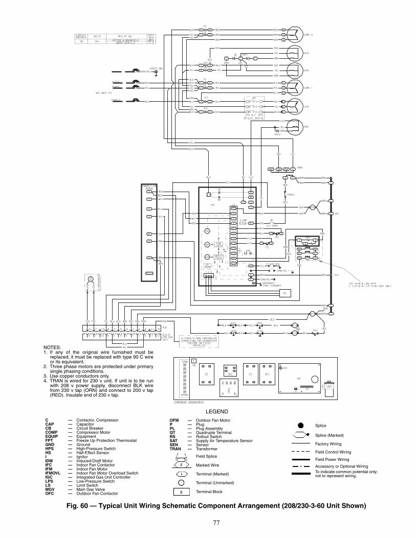
77
Fig. 60 — Typical Unit Wiring Schematic Component Arrangement (208/230-3-60 Unit Shown)
LEGEND
OFM — Outdoor Fan MotorP — PlugPL — Plug AssemblyQT — Quadruple TerminalRS — Rollout SwitchSAT — Supply Air Temperature SensorSEN — SensorTRAN — Transformer
Field Splice
Marked Wire
Terminal (Marked)
Terminal (Unmarked)
Terminal Block
C — Contactor, CompressorCAP — CapacitorCB — Circuit BreakerCOMP — Compressor MotorEQUIP — EquipmentFPT — Freeze Up Protection ThermostatGND — GroundHPS — High-Pressure SwitchHS — Hall-Effect SensorI — IgnitorIDM — Induced-Draft MotorIFC — Indoor Fan ContactorIFM — Indoor Fan MotorIFMOVL — Indoor Fan Motor Overload SwitchIGC — Integrated Gas Unit ControllerLPS — Low-Pressure SwitchLS — Limit SwitchMGV — Main Gas ValveOFC — Outdoor Fan Contactor
Splice
Splice (Marked)
Factory Wiring
Field Control Wiring
Field Power Wiring
Accessory or Optional WiringTo indicate common potential only;not to represent wiring.
NOTES:1. If any of the original wire furnished must be
replaced, it must be replaced with type 90 C wireor its equivalent.
2. Three phase motors are protected under primarysingle phasing conditions.
3. Use copper conductors only.4. TRAN is wired for 230 v unit. If unit is to be run
with 208 v power supply, disconnect BLK wirefrom 230 v tap (ORN) and connect to 200 v tap(RED). Insulate end of 230 v tap.

78
EconoMi$er IV Troubleshooting — See Table 46for EconoMi$er IV logic.
A functional view of the EconoMi$er IV is shown inFig. 61. Typical settings, sensor ranges, and jumper positionsare also shown. An EconoMi$er IV simulator program isavailable from Carrier to help with EconoMi$er IV trainingand troubleshooting.ECONOMI$ER IV PREPARATION — This procedure isused to prepare the EconoMi$er IV for troubleshooting. Notroubleshooting or testing is done by performing the followingprocedure.NOTE: This procedure requires a 9-v battery, 1.2 kilo-ohmresistor, and a 5.6 kilo-ohm resistor which are not suppliedwith the EconoMi$er IV.
1. Disconnect power at TR and TR1. All LEDs should beoff. Exhaust fan contacts should be open.
2. Disconnect device at P and P1.3. Jumper P to P1.4. Disconnect wires at T and T1. Place 5.6 kilo-ohm resistor
across T and T1.5. Jumper TR to 1.6. Jumper TR to N.7. If connected, remove sensor from terminals SO and +.
Connect 1.2 kilo-ohm 4074EJM checkout resistor acrossterminals SO and +.
8. Put 620-ohm resistor across terminals SR and +.9. Set minimum position, DCV set point, and exhaust
potentiometers fully CCW (counterclockwise).10. Set DCV maximum position potentiometer fully CW
(clockwise).11. Set enthalpy potentiometer to D.12. Apply power (24 vac) to terminals TR and TR1.DIFFERENTIAL ENTHALPY — To check differentialenthalpy:
1. Make sure EconoMi$er IV preparation procedure hasbeen performed.
2. Place 620-ohm resistor across SO and +.3. Place 1.2 kilo-ohm resistor across SR and +. The Free
Cool LED should be lit.4. Remove 620-ohm resistor across SO and +. The Free
Cool LED should turn off.5. Return EconoMi$er IV settings and wiring to normal
after completing troubleshooting.SINGLE ENTHALPY — To check single enthalpy:
1. Make sure EconoMi$er IV preparation procedure hasbeen performed.
2. Set the enthalpy potentiometer to A (fully CCW). TheFree Cool LED should be lit.
3. Set the enthalpy potentiometer to D (fully CW). The FreeCool LED should turn off.
4. Return EconoMi$er IV settings and wiring to normalafter completing troubleshooting.
DCV (Demand Controlled Ventilation) AND POWEREXHAUST — To check DCV and Power Exhaust:
1. Make sure EconoMi$er IV preparation procedure hasbeen performed.
2. Ensure terminals AQ and AQ1 are open. The LED forboth DCV and Exhaust should be off. The actuatorshould be fully closed.
3. Connect a 9-v battery to AQ (positive node) and AQ1(negative node). The LED for both DCV and Exhaustshould turn on. The actuator should drive to between 90and 95% open.
4. Turn the Exhaust potentiometer CW until the ExhaustLED turns off. The LED should turn off when thepotentiometer is approximately 90%. The actuator shouldremain in position.
5. Turn the DCV set point potentiometer CW until the DCVLED turns off. The DCV LED should turn off when thepotentiometer is approximately 9 v. The actuator shoulddrive fully closed.
6. Turn the DCV and Exhaust potentiometers CCW untilthe Exhaust LED turns on. The exhaust contacts willclose 30 to 120 seconds after the Exhaust LED turns on.
7. Return EconoMi$er IV settings and wiring to normalafter completing troubleshooting.
DCV MINIMUM AND MAXIMUM POSITION — To checkthe DCV minimum and maximum position:
1. Make sure EconoMi$er IV preparation procedure hasbeen performed.
2. Connect a 9-v battery to AQ (positive node) and AQ1(negative node). The DCV LED should turn on. Theactuator should drive to between 90 and 95% open.
3. Turn the DCV Maximum Position potentiometer to mid-point. The actuator should drive to between 20 and 80%open.
4. Turn the DCV Maximum Position potentiometer to fullyCCW. The actuator should drive fully closed.
5. Turn the Minimum Position potentiometer to midpoint.The actuator should drive to between 20 and 80% open.
6. Turn the Minimum Position Potentiometer fully CW. Theactuator should drive fully open.
7. Remove the jumper from TR and N. The actuator shoulddrive fully closed.
8. Return EconoMi$er IV settings and wiring to normalafter completing troubleshooting.
SUPPLY-AIR INPUT — To check supply-air input:1. Make sure EconoMi$er IV preparation procedure has
been performed.2. Set the Enthalpy potentiometer to A. The Free Cool LED
turns on. The actuator should drive to between 20 and80% open.
3. Remove the 5.6 kilo-ohm resistor and jumper T to T1.The actuator should drive fully open.
4. Remove the jumper across T and T1. The actuator shoulddrive fully closed.
5. Return EconoMi$er IV settings and wiring to normalafter completing troubleshooting.
ECONOMI$ER IV TROUBLESHOOTING COMPLE-TION — This procedure is used to return the EconoMi$er IVto operation. No troubleshooting or testing is done by perform-ing the following procedure.
1. Disconnect power at TR and TR1.2. Set enthalpy potentiometer to previous setting.3. Set DCV maximum position potentiometer to previous
setting.4. Set minimum position, DCV set point, and exhaust
potentiometers to previous settings.5. Remove 620-ohm resistor from terminals SR and +.6. Remove 1.2 kilo-ohm checkout resistor from terminals
SO and +. If used, reconnect sensor from terminals SO and+.
IMPORTANT: Be sure to record the positions of all poten-tiometers before starting troubleshooting.

79
7. Remove jumper from TR to N.8. Remove jumper from TR to 1.9. Remove 5.6 kilo-ohm resistor from T and T1. Reconnect
wires at T and T1.
10. Remove jumper from P to P1. Reconnect device at P andP1.
11. Apply power (24 vac) to terminals TR and TR1.
Table 46 — EconoMi$er IV Input/Output Logic
*For single enthalpy control, the module compares outdoorenthalpy to the ABCD set point.
†Power at N terminal determines Occupied/Unoccupied setting:24 vac (Occupied), no power (Unoccupied).
**Modulation is based on the supply air sensor signal.††Modulation is based on the DCV signal.
***Modulation is based on the greater of DCV and supply air sensorsignals, between minimum position and either maximum position(DCV) or fully open (supply air signal).
†††Modulation is based on the greater of DCV and supply airsensor signals, between closed and either maximum position(DCV) or fully open (supply air signal).
INPUTS OUTPUTS
Demand ControlVentilation (DCV)
Enthalpy*Y1 Y2
Compressor N Terminal†
Outdoor Return Stage1
Stage2
Occupied UnoccupiedDamper
Below set(DCV LED Off)
High(Free Cooling LED Off)
Low On On On On Minimum position ClosedOn Off On OffOff Off Off Off
Low(Free Cooling LED On)
High On On On Off Modulating** (between min.position and full-open)
Modulating** (betweenclosed and full-open)On Off Off Off
Off Off Off Off Minimum position ClosedAbove set(DCV LED On)
High(Free Cooling LED Off)
Low On On On On Modulating†† (between min.position and DCV maximum)
Modulating†† (betweenclosed and DCVmaximum)
On Off On OffOff Off Off Off
Low(Free Cooling LED On)
High On On On Off Modulating*** Modulating†††On Off Off OffOff Off Off Off
Fig. 61 — EconoMi$er IV Functional View

Manufacturer reserves the right to discontinue, or change at any time, specifications or designs without notice and without incurring obligations.Catalog No. 04-53480015-01 Printed in U.S.A. Form 48T-6SI Pg 80 9-05 Replaces: 48T-4SIBook 1 4
Tab 1a 6a
Copyright 2005 Carrier Corporation
INDEXAccess panels 23Altitude compensation 64Barometric flow capacity 25Burner ignition 73Burner rack 74Burner section 73Burner spark gap 64Carrier Comfort Network 19Charging chart, refrigerant 69-72Clearance 10, 11CO2 sensorConfiguration 30Settings 28, 30
Combustion blower wheel 63CompressorLubrication 68Mounting 63Rotation 63
Condensate drainCleaning 67Location 2, 4
Condenser coil 6, 8Cleaning 67
Condenser fan 6, 8Adjustment 68
Control circuitWiring 12, 13Wiring raceway 18
Convenience outlet 18Demand control ventilation 29Dehumidification 30
Dimensions 3, 10, 11Ductwork 2EconoMi$er2 22-254 to 20 mA control 25
EconoMi$er IV 22-30Adjustment 68Components 22Damper movement 29Dry bulb temperature sensor 26Troubleshooting 78, 79Wiring 24
Electrical connections 12Electrical data 14-17Enthalpy changeover set points 28Enthalpy sensor 22Evaporator coil 6, 8Cleaning 67
Evaporator fan motorEfficiency 31Lubrication 68Motor data 32Performance 33-62Pulley adjustment 31Pulley setting 6, 8, 31Speed 6, 8
Factory-installed options 18-30Convenience outlet 18EconoMi$er IV 22-30EconoMi$er2 22-25Manual outdoor air damper 18Novar controls 18PremierLink™ controls 19-21
FilterCleaning 67Installation 24Size 7, 9
Flue gas passageways 73Flue hood 12Freeze protection thermostat 7, 9, 68Gas connection 7, 9Gas input 7, 9Gas piping 12, 63Gas pressure 1, 7, 9, 12
Heat anticipator settings 7, 9, 13Heat exchanger 7, 9High flow valves 63High pressure switch 7, 9, 68Horizontal units 2IAQ sensor 19, 27Integrated gas controller 64Error codes 73
Leak test 63Limit switch 73Liquid propane 7, 9Low pressure switch 7, 9, 68Main burners 64, 73Manual outdoor air damper 18, 68MountingCompressor 63Unit 4
Natural gas 7, 9Novar controls 18Operating sequence 65-67Cooling 65EconoMi$er IV 65EconoMi$er2 65-67Heating 65
Outdoor air hood 19, 23Outdoor air inlet screens 63Outdoor air temperature sensor 19, 24Physical data 6-9Power supply 12Wiring 13
PremierLink controls 19-21Pre-start-up 63Pressure, dropReturn air 25
Pressure switchesHigh pressure 7, 9Low pressure 7, 9
RefrigerantCharge 68-72Type 6, 8
Refrigerant service ports 63Replacement parts 73Return air filter 7, 9, 63Return air temperature sensor 27Rigging unit 4, 5Roof curbAssembly 1Dimensions 3Connector package 3Leveling tolerances 4Weight 6, 8
Safety considerations 1Safety relief 65Service 67-74Service ports 63Slab mount 2Start-up 63-67Start-up checklist CL-1Supply-air temperature sensor 19, 26Thermostat 12, 13, 29Troubleshooting 75-79Ventilation 65WeightCorner 10, 11EconoMi$er IV 6, 8, 10, 11Unit 5, 6, 8, 10, 11
Wiring4 to 20 mA control 25Differential enthalpy 22EconoMi$er2 25EconoMi$er IV 24Power connections 13PremierLink 21Thermostat 13Unit 77


Manufacturer reserves the right to discontinue, or change at any time, specifications or designs without notice and without incurring obligations.Catalog No. 04-53480015-01 Printed in U.S.A. Form 48T-6SI Pg CL-1 9-05 Replaces: 48T-4SIBook 1 4
Tab 1a 6a
Copyright 2005 Carrier Corporation
--
--
--
--
--
--
--
--
--
--
--
--
--
--
--
--
--
--
--
--
--
--
--
--
--
--
--
--
--
--
--
--
--
--
--
--
--
--
--
--
--
--
--
--
--
--
--
--
--
--
--
--
--
--
--
--
--
--
--
--
--
--
--
--
--
--
--
--
--
--
--
--
--
--
--
--
--
--
--
--
--
--
--
--
--
--
---
--
--
--
--
--
--
--
--
--
-C
UT
ALO
NG
DO
TT
ED
LIN
EC
UT
ALO
NG
DO
TT
ED
LIN
E
START-UP CHECKLIST(Remove and Store in Job File)
I. PRELIMINARY INFORMATION
MODEL NO.:________________________________ SERIAL NO.: ___________________________________
DATE:______________________________________ TECHNICIAN: __________________________________
UNIT NO.: __________________________________ JOB LOCATION: ________________________________
JOB NAME: ____________________________________
II. PRE-START-UP (insert checkmark in box as each item is completed)
� VERIFY THAT ALL PACKING MATERIALS HAVE BEEN REMOVED FROM UNIT
� REMOVE SHIPPING TIEDOWN BANDS ON COMPRESSOR (SIZE 014 ONLY) PER INSTALLATIONINSTRUCTIONS
� VERIFY THAT CONDENSATE CONNECTION IS INSTALLED PER INSTALLATION INSTRUCTIONS
� CHECK ALL ELECTRICAL CONNECTIONS AND TERMINALS FOR TIGHTNESS
� CHECK GAS PIPING FOR LEAKS
� CHECK THAT INDOOR-AIR FILTERS ARE CLEAN AND IN PLACE
� VERIFY THAT UNIT INSTALLATION IS LEVEL
� CHECK FAN WHEELS AND PROPELLERS FOR LOCATION IN HOUSING/ORIFICE AND SETSCREW TIGHTNESS
� ENSURE BELT TENSION IS CORRECT AND BLOWER PULLEYS ARE PROPERLY ALIGNED.
� VERIFY INSTALLATION OF ECONOMIZER HOOD (IF EQUIPPED).
III. START-UPELECTRICAL
TEMPERATURES AND PRESSURES
� VERIFY REFRIGERANT CHARGE USING CHARGING TABLES
� VERIFY THAT 3-PHASE SCROLL COMPRESSOR ROTATING IN CORRECT DIRECTION (48TF014 AND48TM009-014 ONLY)
GENERAL
� SET ECONOMIZER MINIMUM VENT POSITION AND CHANGEOVER SETTINGS TO JOB REQUIREMENTS(IF EQUIPPED)
SUPPLY VOLTAGE L1-L2 L2-L3 L3-L1COMPRESSOR AMPS L1 L2 L3COMPRESSOR AMPS L1 L2 L3INDOOR-FAN AMPS L1 L2 L3
OUTDOOR-AIR TEMPERATURE DBRETURN-AIR TEMPERATURE DB WBCOOLING SUPPLY AIR DB WBGAS HEAT SUPPLY AIR DB
GAS INLET PRESSURE IN. WGGAS MANIFOLD PRESSURE IN. WG (HI FIRE) IN. WG (LO FIRE)REFRIGERANT SUCTION PRESSURE PSIG — CIRCUIT NO. 1 PSIG — CIRCUIT NO. 2REFRIGERANT TEMP. (SUCTION) PRESSURE CIRCUIT NO. 1 CIRCUIT NO. 2REFRIGERANT DISCHARGE PSIG — CIRCUIT NO. 1 PSIG — CIRCUIT NO. 2DISCHARGE TEMPERATURE °F/C — CIRCUIT NO. 1 °F/C — CIRCUIT NO. 2