installation/ owner's manual air conditioner
TRANSCRIPT

INSTALLATION/OWNER'S MANUAL
PDI STANDARDPPWRDB000
AIRCONDITIONER
www.lg.com
Please read this installation manual completely before installing the product.Installation work must be performed in accordance with the national wiring standards by authorized personnel only.Please retain this installation manual for future reference after reading it thoroughly.
P/NO : MFL67982907
ENG
LISH
ITALIA
NO
ESPA
ÑO
LFRA
NÇA
ISD
EUTSC
HPORTUGUÊS
TÜR
KÇ
EРУССКИЙ ЯЗЫК
1,MFL67982907,영영 2017. 7. 13. 영영 1:13 Page 1

2 TIPS FOR SAVING ENERGY
ENG
LISH
TIPS FOR SAVING ENERGYHere are some tips that will help you minimize the power consumption when you use the airconditioner. You can use your air conditioner more efficiently by referring to the instructionsbelow:
• Do not cool excessively indoors. This may be harmful for your health and may consume moreelectricity.
• Block sunlight with blinds or curtains while you are operating the air conditioner.
• Keep doors or windows closed tightly while you are operating the air conditioner.
• Adjust the direction of the air flow vertically or horizontally to circulate indoor air.
• Speed up the fan to cool or warm indoor air quickly, in a short period of time.
• Open windows regularly for ventilation as the indoor air quality may deteriorate if the air con-ditioner is used for many hours.
• Clean the air filter once every 2 weeks. Dust and impurities collected in the air filter may blockthe air flow or weaken the cooling / dehumidifying functions.
For your records
Staple your receipt to this page in case you need it to prove the date of purchase or for warranty purposes. Write the model number and the serial number here:
Model number :
Serial number :
You can find them on a label on the side of each unit.
Dealer’s name :
Date of purchase :
1,MFL67982907,영영 2017. 7. 13. 영영 1:13 Page 2

IMPORTANT SAFETY INSTRUCTIONS
IMPORTANT SAFETY INSTRUCTIONSREAD ALL INSTRUCTIONS BEFORE USING THE APPLIANCE.Always comply with the following precautions to avoid dangerous situations andensure peak performance of your product
WARNINGIt can result in serious injury or death when the directions are ignored
CAUTIONIt can result in minor injury or product damage when the directions are ignored
WARNING• Installation or repairs made by unqualified persons can result in hazards to you
and others.• Installation work must be performed in accordance with the National Electric
Code by qualified and authorized personnel only.• The information contained in the manual is intended for use by a qualified
service technician familiar with safety procedures and equipped with theproper tools and test instruments.
• Failure to carefully read and follow all instructions in this manual can result inequipment malfunction, property damage, personal injury and/or death.
WARNINGInstallation
• Be sure to request to the service center or installation specialty store wheninstalling products. It will cause fire or electric shock or explosion or injury.
• Request to the service center or installation specialty store when reinstallingthe installed product. It will cause fire or electric shock or explosion or injury.
• Do not disassemble, fix, and modify products randomly.It will cause fire or electric shock.
In-use• Do not place flammable stuffs close to the product. It will cause fire.• Do not allow water to run into the product.
It will cause electric shock or breakdown.• Do not give the shock to the product.
It will cause breakdown when giving the shock to the product.
!
!
!
!
3 ENG
LISH
1,MFL67982907,영영 2017. 7. 13. 영영 1:13 Page 3

4 IMPORTANT SAFETY INSTRUCTIONS
ENG
LISH
• Request to the service center or installation specialty store when the productbecomes wet. It will cause fire or electric shock.
• Do not give the shock using sharp and pointed objects.It will cause breakdown by damaging parts.
CAUTIONIn-use
• Do not clean using the powerful detergent like solvent but use soft cloths. Itwill cause fire or product deformation.
• Do not press the screen using powerful pressure or select two buttons. It willcause product breakdown or malfunction.
• Do not touch or pull the lead wire with wet hands.It will cause product breakdown or electric shock.
!
According to IEC 60335-1This appliance is not intended for use by person (including children) with reducedphysical, or mental capabilities, or lack of experience and knowledge, unless theyhave been given supervision or instruction concerning use of the appliance by aperson responsible for their safety. Children should be supervised to ensure thatthey do not play with the appliance.
According to EN 60335-1This appliance can be used by children aged from 8 years and above and personwith reduced physical, sensory or mental capabilities or lack of experience andknowledge if they have been given supervision or instruction concerning use ofthe appliance in a safe way and understand the hazards involved. Children shallnot play with the appliance. Cleaning and user maintenance shall not be made bychildren without supervision.
Disposal of your old appliance
1 When this crossed-out wheeled bin symbol is attached to a product it means the productis covered by the European Directive 2002/96/EC.
2 All electrical and electronic products should be disposed of separately from the municipalwaste stream via designated collection facilities appointed by the government or the localauthorities.
3 The correct disposal of your old appliance will help prevent potential negative conse-quences for the environment and human health.
4 For more detailed information about disposal of your old appliance, please contact yourcity office, waste disposal service or the shop where you purchased the product.
1,MFL67982907,영영 2017. 7. 13. 영영 1:13 Page 4

TABLE OF CONTENTS 5
TABLE OF CONTENTS
2 TIPS FOR SAVING EN-ERGY
3 IMPORTANT SAFETY IN-STRUCTIONS
6 NAME OF EACH PART
7 COMPONENTS
8 INSTALLATION METHOD8 Diagram of overall product configura-
tion
12 How to wire the product (when EHPproduct is connected)
13 How to wire the product (when GHPproduct is connected)
14 Wiring
17 SETTING AND USINGMETHOD
17 Glossary
18 Setting
20 Setting up detailed functions (EHPproducts)
26 Setting detailed functions (GHP prod-ucts)
32 How to Use Power Indicator (EHPproducts)
35 How to Use the Power Indicator (GHPproducts)
39 Operating condition display
ENG
LISH
1,MFL67982907,영영 2017. 7. 13. 영영 1:13 Page 5

6 NAME OF EACH PART
ENG
LISH
NAME OF EACH PART
① Front cover
② LED display Displays current status of power indicator
③ Menu button Use for checking initial setting and electric power
④ LCD display Displays setting information and power usage
⑤ SELECT button Use for initial setting
⑥ Navigation button Use for checking initial setting and electric power
⑦ Power supply Supply power for power indicator
POWER WHM
PPWRDB000
ODU
MENU
SELECT
WHM CHECK
⑦ Power supply
① Front cover
② LED display
③ Menu button
④ LCD display
⑤ SELECT button
② LED display
⑥ Navigation button
POWER WHM
MENU
SELECT
ODU WHM CHECK
1,MFL67982907,영영 2017. 7. 13. 영영 1:13 Page 6
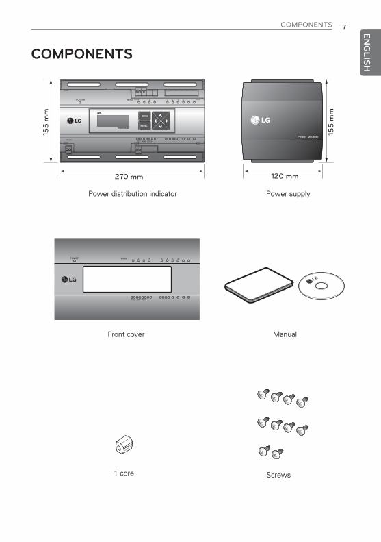
COMPONENTS 7 ENG
LISH
COMPONENTS15
5 m
m
270 mm 120 mm
155
mm
POWER WHM
PPWRDB000
ODU
MENU
SELECT
WHM CHECK
Power distribution indicator Power supply
Front cover
1 core Screws
POWER WHM
ODU WHM CHECK
Manual
1,MFL67982907,영영 2017. 7. 13. 영영 1:16 Page 7

8 INSTALLATION METHOD
ENG
LISH
INSTALLATION METHODDiagram of overall product configurationWhen interlocked to pulse type wattmeter• When interlocked to EHP product
- Independent Operation of Power Indicator (interlocked to EHP products)
Power cable for 3 phase 4 wirePower cable for single phaseCommunication cable (2 wire shielded cable): Between outdoor unit and central controllerCommunication cable (2 wire shielded cable): Between indoor unit and outdoor unitPulse signal wireRefrigerant pipe
Power Insingle phase220-240 V~,
50/60 Hz
Wattmeter
WattmeterPower In 3
phase 4 wire380-415 V 3N~,
50/60 Hz
Pulse signal
(00) (01) (02) (03)
Powe
r cab
le o
f ind
oor u
nit
Pulse signal
POWER WHM
PPWRDB000
ODU
MENU
SELECT
WHM CHECK
Power Insingle phase220-240 V~,
50/60 Hz
WattmeterPower In 3
phase 4 wire380-415 V 3N~,
50/60 Hz
(00) (01) (02) (03)
(10) (11) (12) (13)
Powe
r cab
le o
f ind
oor u
nit
RS-485
Pulse signalPulse signal
POWER WHM
PPWRDB000
ODU
MENU
SELECT
WHM CHECK
RS-485
1,MFL67982907,영영 2017. 7. 13. 영영 1:13 Page 8

INSTALLATION METHOD 9 ENG
LISH
• Interlocked Operation with Central Controller (interlocked to EHP product)
(00) (01) (02) (03)
(10) (11) (12) (13)
Powe
r cab
le o
f ind
oor u
nit
Power Insingle phase220-240 V~,
50/60 Hz
WattmeterPower In 3
phase 4 wire380-415 V 3N~,
50/60 Hz
Pulse signal
RS-485
RS-485(LGAP)
Pulse signal
POWER WHM
PPWRDB000
ODU
MENU
SELECT
WHM CHECK
Power cable for 3 phase 4 wirePower cable for single phaseCommunication cable (2 wire shielded cable): Between outdoor unit and central controllerCommunication cable (2 wire shielded cable): Between indoor unit and outdoor unitPulse signal wireRefrigerant pipe
CAUTION
• Depending on the electric power, use the wattmeter for remote reading by sending thepulse signal.
• Use the wattmeter with the pulse width of 50 ms ~ 400 ms.• The wattmeter pulse must be able to sink at least 3 mA or more of current in the power
indicator.• Use the wattmeter of 1 W/Pulse, 2 W/Pulse, 4 W/Pulse, 6 W/Pulse, 8 W/Pulse, 10
W/Pulse, 100 W/Pulse, PT/CT (1 ~ 50 000).• When setting the wattmeter, set it to Slave Mode.• Maximum of 2 wattmeters can be installed.• The distance between power indicator and wattmeter should be shorter than 10 m in
normal circumstance.• When electrical or mechanical noise is expected, more shorter wiring is needed.• For watt-hour meter setting, inquire to the corresponding vendor
!
h EHP (Electric Heat Pump): It is an electric air conditioner to drive the compressor by electric power.
1,MFL67982907,영영 2017. 7. 13. 영영 1:13 Page 9

10 INSTALLATION METHOD
ENG
LISH
• When interlocked to GHP product- Independent Operation of Power Indicator (interlocked to GHP product)
Wattmeter
Pulse signal(Power)
Pulse signal(Gas)
Power In 3phase 4 wire
380-415 V 3N~,50/60 Hz
Gas meter
(00) (01) (02) (03)
RS-485
POWER WHM
PPWRDB000
ODU
MENU
SELECT
WHM CHECK
Power cable for 3 phase 4 wirePower cable for single phaseCommunication cable (2 wire shielded cable): Between outdoor unit and central controllerCommunication cable (2 wire shielded cable): Between indoor unit and outdoor unitPulse signal wireRefrigerant pipeGas pipePulse signal wire(Gas)
CAUTION
• Use the wattmeter for remote reading to send pulse signal depending on wattage.• Use the wattmeter with the pulse width of 50 ms ~ 400 ms.• The wattmeter pulse must be able to sink at least 3 mA or more of current in the power indicator.• Use the wattmeter of 1 W/Pulse, 2 W/Pulse, 4 W/Pulse, 6 W/Pulse, 8 W/Pulse, 10 W/Pulse,
100 W/Pulse, PT/CT(1 ~ 50 000).• Use the gas meter for remote reading to send pulse signal depending on gas consumption.• Use the gas meter with the pulse width of 50 ms or more.• Use the gas meter containing the max. gas pressure of 0.2 m3/h ~ 10 m3/h.• Gas meter pulse must be able to sink at least 3 mA of current or more in the power indicator.• Use the gas meters for 1 ℓ/Pulse, 2 ℓ/Pulse, 4 ℓ /Pulse, 6 ℓ/Pulse, 8 ℓ/Pulse, 10 ℓ/Pulse,
100 ℓ/Pulse, VT&Pr(1 ~ 50 000).• Set to Master Mode when setting the wattmeter or gas meter.• Wattmeter or gas meter can be installed up to 1.• Connection cable for the power indicator and wattmeter (gas meter) must not exceed 10 m
in normal circumstance.• Reduce the length of connection cable if there is any electrical or mechanical noise on the site.• For watt-hour meter and gas meter setting, inquire to the corresponding vendor
h GHP (Gas engine Heat Pump): It is a gas air-conditioner to drive the compressor with LNG or LPG asa heat source and the gas engine electric power.
!
1,MFL67982907,영영 2017. 7. 13. 영영 1:13 Page 10

INSTALLATION METHOD 11 ENG
LISH
- When linked with the GHP product, the central controller is linked only possible model ofACS IV series or later.
Wattmeter
Pulse signal(Power)
Pulse signal(Gas)
Power In 3phase 4 wire
380-415 V 3N~,50/60 Hz
Gas meter
(00) (01) (02) (03)
RS-485(LGAP)
RS-485
POWER WHM
PPWRDB000
ODU
MENU
SELECT
WHM CHECK
Power cable for 3 phase 4 wirePower cable for single phaseCommunication cable (2 wire shielded cable): Between outdoor unit and central controllerCommunication cable (2 wire shielded cable): Between indoor unit and outdoor unitPulse signal wireRefrigerant pipeGas pipePulse signal wire(Gas)
CAUTION
• Use the wattmeter for remote reading to send pulse signal depending on wattage.• Use the wattmeter with the pulse width of 50 ms ~ 400 ms.• The wattmeter pulse must be able to sink at least 3 mA or more of current in the power indicator.• Use the wattmeter for 1 W/Pulse, 2 W/Pulse, 4 W/Pulse, 6 W/Pulse, 8 W/Pulse, 10 W/Pulse,
100 W/Pulse, PT/CT(1 ~ 50 000).• Use the gas meter for remote reading to send pulse signal depending on gas consumption.• Use the gas meter with the pulse width of 50 ms or more.• Use the gas meter containing the max. gas pressure of 0.2 m3/h ~ 10 m3/h.• Gas meter pulse must be able to sink at least 3 mA of current or more in the power indicator.• Use the gas meters for 1 ℓ/Pulse, 2 ℓ/Pulse, 4 ℓ/Pulse, 6 ℓ/Pulse, 8 ℓ/Pulse, 10 ℓ/Pulse,
100 ℓ/Pulse, VT&Pr(1 ~ 50 000).• Set to Slave Mode when setting the wattmeter or gas meter.• Wattmeter or gas meter can be installed up to 1.• Connection cable for the power indicator and wattmeter (gas meter) must not exceed 10 m in
normal circumstance.• Reduce the length of connection cable if there is any electrical or mechanical noise on the site.• For watt-hour meter and gas meter setting, inquire to the corresponding vendor
!
1,MFL67982907,영영 2017. 7. 13. 영영 1:13 Page 11
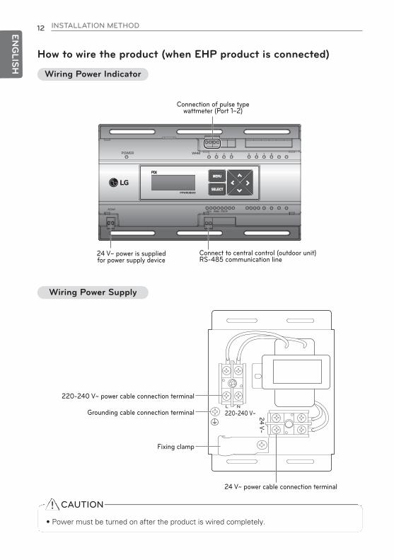
12 INSTALLATION METHOD
ENG
LISH
How to wire the product (when EHP product is connected)
Connect to central control (outdoor unit) RS-485 communication line
24 V~ power is suppliedfor power supply device
POWER WHM
PPWRDB000
ODU
MENU
SELECT
WHM CHECK
MENU
SELECT
Connection of pulse typewattmeter (Port 1~2)
Wiring Power Indicator
220-240 V~L N
24 V~
220-240 V~ power cable connection terminal
Grounding cable connection terminal
Fixing clamp
24 V~ power cable connection terminal
Wiring Power Supply
CAUTION
• Power must be turned on after the product is wired completely.
!
1,MFL67982907,영영 2017. 7. 13. 영영 1:13 Page 12

INSTALLATION METHOD 13 ENG
LISH
How to wire the product (when GHP product is connected)
Connected to pulse-typewattmeter (Port 1)Connected to pulse-typegas meter (Port 2)
POWER WHM
PPWRDB000
ODU
MENU
SELECT
WHM CHECK
Connect to central control (outdoor unit) RS-485 communication line24 V~ power is supplied
for power supply device
Wiring Power Indicator
220-240 V~L N
24 V~
220-240 V~ power cable connection terminal
Grounding cable connection terminal
Fixing clamp
24 V~ power cable connection terminal
Wiring Power Supply
CAUTION
• Power supply must be applied after wiring the product is completed, if applicable.
!
1,MFL67982907,영영 2017. 7. 13. 영영 1:14 Page 13
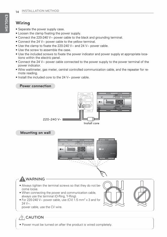
14 INSTALLATION METHOD
ENG
LISH
Wiring• Separate the power supply case.• Loosen the clamp fixating the power supply.• Connect the 220-240 V~ power cable to the black and grounding terminal.• Connect the 24 V~ power cable to the yellow terminal.• Use the clamp to fixate the 220-240 V~ and 24 V~ power cable.• Use the screw to assemble the case.• Use the included screws to fixate the power indicator and power supply at appropriate loca-
tions within the electric panel.• Connect the 24 V~ power cable connected to the power supply to the power terminal of the
power indicator.• Wire wattmeter, gas meter, central controlled communication cable, and the repeater for re-
mote reading.• Install the included core to the 24 V~ power cable.
POWER WHM
PPWRDB000
ODU
MENU
SELECT
WHM CHECK
POWER WHM
PPWRDB000
ODU
MENU
SELECT
WHM CHECK
220-240 V~Install core
Power connection
POWER WHM
PPWRDB000
ODU
MENU
SELECT
WHM CHECK
Mounting on wall
CAUTION
• Power must be turned on after the product is wired completely.
!
WARNING
• Always tighten the terminal screws so that they do not be-come loose.
• When connecting the power and communication cable,always use the terminal (O-Ring, Y-Ring).
• For 220-240 V~ power cable, use (CV) 1.5 mm2 x 3 and for 24 V~.power cable, use the CV wire.
!
1,MFL67982907,영영 2017. 7. 13. 영영 1:14 Page 14

INSTALLATION METHOD 15 ENG
LISH
Connect the wattmeter and communication cable (EHP products)
CAUTION1. Please read the manual carefully, before using the product.2. The installation requires expert skills, and it should be installed by the
service or other shops specialized in the installation and recognized byour company.
3. For all the problems arising after installation by someone who has norelevant qualifications, our company will not provide free service
Outdoor Unit(Central controller)
Pulse typewattmeter
Pulse typewattmeter
POWER WHM
PPWRDB000
ODU
MENU
SELECT
WHM CHECK
CAUTION
• The color and polarity of the signal wire may be different from the details indicated on thecase depending on the manufacturer of wattmeter. [Black: (-), white: (+)]
• When connecting the 485 communication cable, make sure to check the A, B polarity.• After connecting the wattmeter, check whether the signal is connected through the LED.• Power indicator and Pulse Type wattmeter must be installed in same panel.
!
When connecting the pulse-type wattmeter
• Independent Operation of Power Indicator (interlocked to EHP product)
1,MFL67982907,영영 2017. 7. 14. 영영 1:13 Page 15

16 INSTALLATION METHOD
ENG
LISH
CAUTION1. Please read the manual carefully, before using the product.2. The installation requires expert skills, and it should be installed by the
service or other shops specialized in the installation and recognized byour company.
3. For all the problems arising after installation by someone who has norelevant qualifications, our company will not provide free service
POWER WHM
PPWRDB000
ODU
MENU
SELECT
WHM CHECK
Pulse typewattmeter
Pulse typegas meter
Outdoor Unit(Central controller)
CAUTION
• The color and polarity of the signal wire may be different from the details indicated on thecase depending on the manufacturer of wattmeter. [Black: (-), white: (+)]
• When connecting the 485 communication cable, make sure to check the A, B polarity.• After connecting the wattmeter, check whether the signal is connected through the LED.• Install the power indicator and the pulse-type wattmeter on the same panel.• Make sure that the pulse lines of the wattmeter and gas meter are connected to the
correct positions (wattmeter : port 1, gas meter : port 2)
!
When connecting the pulse-type wattmeter / gas meter
Connection of wattmeter, gas meter and communication cable (GHP products)
1,MFL67982907,영영 2017. 7. 14. 영영 1:13 Page 16
SETTING AND USING METHOD 17 ENG
LISH
SETTING AND USING METHODGlossary• EHP (Electric Heat Pump)
It is an electric air conditioner to drive the compressor by electric power.• GHP (Gas engine Heat Pump)
GHP is a gas air conditioner to drive the compressor with LNG and LPG gas as a heat sourceand power supply for gas engine.
• WHM: wattmeter• LHM: gas meter• ODU: Outdoor Unit• IDU: Indoor Unit• STANDBY P: Standby Power• NOT USE: setting as disabled• CT: deflector device• PT: transforming equipment• VT: volume adjustment device• Pr: gauge integer
1,MFL67982907,영영 2017. 7. 13. 영영 1:14 Page 17

18 SETTING AND USING METHOD
ENG
LISH
• If entering the setting screen for the first time.- After turning power on, press the ‘MENU’ button and the ‘SELECT’ button at the sametime and the screen will change to the screen where you can select the product connec-tion type. Select the product type to connect, and then press the ‘SELECT’ button.Then, the selection of the product will be saved and the screen will be switched to themain standby screen.According to the product ship-out date, standby screen version may be different
Setting
Description of button function
Enter function setting mode
- MENU button: Move to standby screen after setting is completed. Use for reading wattmeter
- Direction button: Move to item to set
- SELECT button: Enter applicable setting window and set changed information
POWER WHM
PPWRDB000
ODU
MENU
SELECT
WHM CHECK
<Main standby screen> <Connection Product Type Setting Screen>
P R O D U C T T Y P E
1 . E H P
2 . G H P
C H A N G E S E T T I N G I N F O !
G
SELECT
MENU
1,MFL67982907,영영 2017. 7. 13. 영영 1:14 Page 18
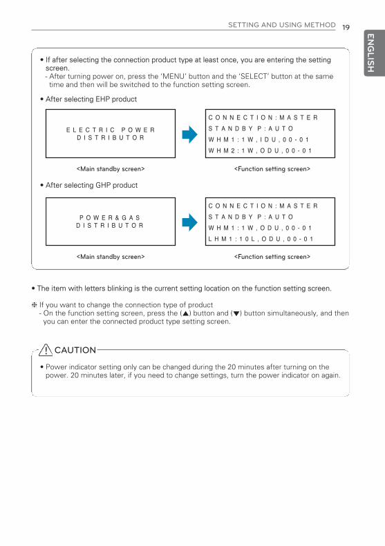
SETTING AND USING METHOD 19 ENG
LISH• If after selecting the connection product type at least once, you are entering the setting
screen.- After turning power on, press the ‘MENU’ button and the ‘SELECT’ button at the sametime and then will be switched to the function setting screen.
• The item with letters blinking is the current setting location on the function setting screen.
h If you want to change the connection type of product- On the function setting screen, press the (▲) button and (▼) button simultaneously, and thenyou can enter the connected product type setting screen.
• After selecting GHP product
• After selecting EHP product
<Main standby screen> <Function setting screen>
E L E C T R I C P O W E RD I S T R I B U T O R
C O N N E C T I O N : M A S T E R
S T A N D B Y P : A U T O
W H M 1 : 1 W , I D U , 0 0 - 0 1
W H M 2 : 1 W , O D U , 0 0 - 0 1
<Main standby screen> <Function setting screen>
P O W E R & G A SD I S T R I B U T O R
C O N N E C T I O N : M A S T E R
S T A N D B Y P : A U T O
W H M 1 : 1 W , O D U , 0 0 - 0 1
L H M 1 : 1 0 L , O D U , 0 0 - 0 1
CAUTION
• Power indicator setting only can be changed during the 20 minutes after turning on thepower. 20 minutes later, if you need to change settings, turn the power indicator on again.
!
1,MFL67982907,영영 2017. 7. 13. 영영 1:14 Page 19
20 SETTING AND USING METHOD
ENG
LISH
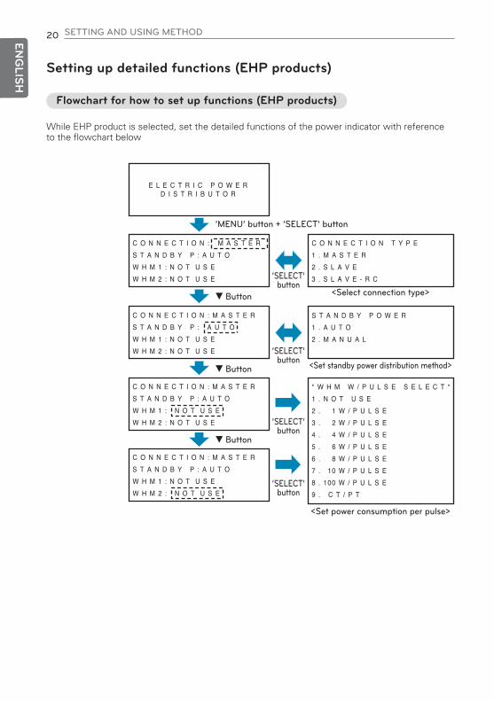
Setting up detailed functions (EHP products)
Flowchart for how to set up functions (EHP products)
While EHP product is selected, set the detailed functions of the power indicator with referenceto the flowchart below
E L E C T R I C P O W E RD I S T R I B U T O R
‘MENU’ button + ‘SELECT’ button
<Select connection type>
<Set power consumption per pulse>
<Set standby power distribution method>
▼ Button
▼ Button
▼ Button
‘SELECT’button
‘SELECT’button
‘SELECT’button
C O N N E C T I O N T Y P E
1 . M A S T E R
2 . S L A V E
3 . S L A V E - R C
S T A N D B Y P O W E R
1 . A U T O
2 . M A N U A L
* W H M W / P U L S E S E L E C T *
1 . N O T U S E
2 . 1 W / P U L S E
3 . 2 W / P U L S E
4 . 4 W / P U L S E
5 . 6 W / P U L S E
6 . 8 W / P U L S E
7 . 10 W / P U L S E
8 . 100 W / P U L S E
9 . C T / P T
‘SELECT’button
C O N N E C T I O N : M A S T E R
S T A N D B Y P : A U T O
W H M 1 : N O T U S E
W H M 2 : N O T U S E
C O N N E C T I O N : M A S T E R
S T A N D B Y P : A U T O
W H M 1 : N O T U S E
W H M 2 : N O T U S E
C O N N E C T I O N : M A S T E R
S T A N D B Y P : A U T O
W H M 1 : N O T U S E
W H M 2 : N O T U S E
C O N N E C T I O N : M A S T E R
S T A N D B Y P : A U T O
W H M 1 : N O T U S E
W H M 2 : N O T U S E
1,MFL67982907,영영 2017. 7. 13. 영영 1:14 Page 20

SETTING AND USING METHOD 21 ENG
LISH
‘SELECT’button
‘SELECT’button
‘SELECT’ button
‘SELECT’button
<Set CT type>
C T & P U L S E R A T I O S E T
C T : 0 0 0 0 0 , P r : 0 0 0 0 0
W H M 1 [ P u l s e / k W h ]
<Selecting the power consumption device>
C O N S U M E U N I T S E L E C T
1 . O U T D O O R U N I T
2 . I N D O O R U N I T
<Setting the connected indoor unit address>
I N D O O R A D D R E S S S E T
( S T A R T ) → ( E N D )
( 0 0 ) → ( 0 0 )
CAUTION
• Power indicator setting only can be changed during the 20 minutes after turning on thepower. Twenty (20) minutes20 minutes later, if you need to change settings, turn the power indicator on again.
!
1,MFL67982907,영영 2017. 7. 13. 영영 1:14 Page 21
22 SETTING AND USING METHOD
ENG
LISH
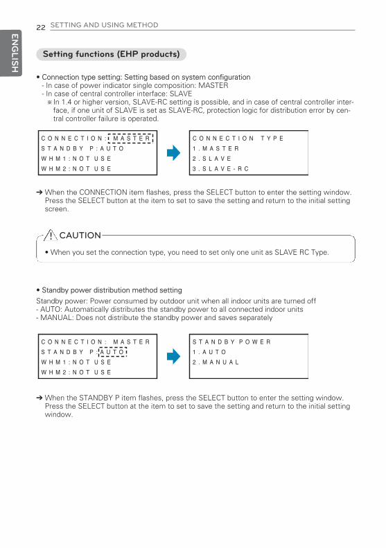
Setting functions (EHP products)
• Connection type setting: Setting based on system configuration- In case of power indicator single composition: MASTER- In case of central controller interface: SLAVE※In 1.4 or higher version, SLAVE-RC setting is possible, and in case of central controller inter-
face, if one unit of SLAVE is set as SLAVE-RC, protection logic for distribution error by cen-tral controller failure is operated.
‘ When the CONNECTION item flashes, press the SELECT button to enter the setting window.Press the SELECT button at the item to set to save the setting and return to the initial settingscreen.
C O N N E C T I O N T Y P E
1 . M A S T E R
2 . S L A V E
3 . S L A V E - R C
C O N N E C T I O N : M A S T E R
S T A N D B Y P : A U T O
W H M 1 : N O T U S E
W H M 2 : N O T U S E
S T A N D B Y P O W E R
1 . A U T O
2 . M A N U A L
C O N N E C T I O N : M A S T E R
S T A N D B Y P : A U T O
W H M 1 : N O T U S E
W H M 2 : N O T U S E
• Standby power distribution method setting
Standby power: Power consumed by outdoor unit when all indoor units are turned off- AUTO: Automatically distributes the standby power to all connected indoor units- MANUAL: Does not distribute the standby power and saves separately
‘ When the STANDBY P item flashes, press the SELECT button to enter the setting window.Press the SELECT button at the item to set to save the setting and return to the initial settingwindow.
CAUTION
• When you set the connection type, you need to set only one unit as SLAVE RC Type.
!
1,MFL67982907,영영 2017. 7. 13. 영영 1:14 Page 22

SETTING AND USING METHOD 23 ENG
LISH
• Wattmeter property setting: Based on the wattmeter type setting, it automatically switches toproperty setting screen.
- Pulse type: Set power consumption by pulse, set attached location (Indoor/Outdoor unitclassification), set indoor unit address
- CT type: Set CT and device constant value, set attached location (Indoor/Outdoor unitclassification), set indoor unit address
• When setting pulse type
Press the (▼) button at the initial setting screen toenter the wattmeter property setting screen.
When the wattmeter item to set flashes, press the SE-LECT button to change to detail setting window.
After setting all wattmeters, press the MENU button to save the setting and move to the initialscreen.
It proceeds in the order of Set power consumption bypulse ’ Set power consumption device ’ Set connectedindoor address.- Set power consumption by pulse (WHM W/PULSE SE-LECT): Enter the value displayed on the wattmeter as powerconsumption per pulse
- Set power consumption device (CONSUME UNIT SELECT): Check and set whether the product on which thewattmeter is installed is a indoor or outdoor unit.※If one indoor unit is set to use both outdoor unit
power distribution and indoor unit power distribution,wattage value is displayed as indoor unit wattagevalue by summing outdoor unit power distributionvalue and indoor unit power distribution value.
- Set connected indoor address (INDOOR ADDRESS SET): Enter the indoor address connected to applicablewattmeter.※After the initial installation, address setting of indoor
unit connected to each port shall not be changed. If itis changed, previous data cannot be used.
After setting the applicable item, press the SELECT buttonto save the setting and to move to the next stage.
C O N N E C T I O N : M A S T E R
S T A N D B Y P : A U T O
W H M 1 : N O T U S E
W H M 2 : N O T U S E
* W H M W / P U L S E S E L E C T *
1 . N O T U S E
2 . 1 W / P U L S E
3 . 2 W / P U L S E
C O N S U M E U N I T S E L E C T
1 . O U T D O O R U N I T
2 . I N D O O R U N I T
C O N N E C T I O N : M A S T E R
S T A N D B Y P : A U T O
W H M 1 : 2 W , O D U , 0 0 - 0 0
W H M 2 : N O T U S E
I N D O O R A D D R E S S S E T
(START) → (END)
(00) → (00)
C O N N E C T I O N : M A S T E R
S T A N D B Y P : A U T O
W H M 1 : N O T U S E
W H M 2 : N O T U S E
Setting detailed properties (EHP products)
Setting information is reflected to the detail settingwindow.
1,MFL67982907,영영 2017. 7. 13. 영영 1:14 Page 23

24 SETTING AND USING METHOD
ENG
LISH
• When setting CT type
Press the (▼) button to set CT/PT from the powerconsumption setting screen per pulse.
When CT/PT item flashes, press the SELECT button to enter CT, Pr input window.
Setting information is reflected to the detail setting win-dow.
It proceeds in the order of Set CT, device constant ’ Setpower consumption device ’ Set connected indoor address.- CT, calibrating constant setting (CT&PULSE RATIO SET)
*CT: As the device to reduce the current so that the meas-uring device can take the measurement, enter the rateindicated on the product to the CT item.Ex) when using 100:1 CT, enter 100 to the CT item.
*Pr: As the device constant value, it is displayed as ratio ofoutput pulse per power consumption of wattmeter.For the device constant value, enter the value dis-played on wattmeter [Pulse/kWh]Ex) when using 2 500 [Pulse/kWh] wattmeter, enter 2 500 to Pr item.
- Power consumption device setting (CONSUME UNIT SELECT): Check whether the product with watt-hour meter installedis outdoor unit or indoor unit first, and perform the setting.※If one indoor unit is set to use both outdoor unit power
distribution and indoor unit power distribution, wattagevalue is displayed as indoor unit wattage value by sum-ming outdoor unit power distribution value and indoorunit power distribution value.
- Connected indoor unit address setting (INDOOR ADDRESS SET): Input the address of the indoor unit connected to the cor-responding watt-hour meter.※After the initial installation, address setting of indoor unit
connected to each port shall not be changed. If it ischanged, previous data cannot be used.
After setting the applicable item, press the SELECT buttonto save the setting and to move to the next stage.
* W H M W / P U L S E S E L E C T *
1 . N O T U S E
2 . 1 W / P U L S E
3 . 2 W / P U L S E D O W N
* W H M W / P U L S E S E L E C T *
7 . 1 0 W / P U L S E U P
8 . 1 0 0 W / P U L S E
9 . C T / P T
C T & P U L S E R A T I O S E T
C T : 0 0 0 0 0 , P r : 0 0 0 0 0
W H M 1 [P u l s e / k W h]
C O N S U M E U N I T S E L E C T
1 . O U T D O O R U N I T
2 . I N D O O R U N I T
C O N N E C T I O N : M A S T E R
S T A N D B Y P : A U T O
W H M 1 : C T / P T, I D U , 0 0 - 0 0
W H M 2 : N O T U S E
I N D O O R A D D R E S S S E T
(START) → (END)
(00) → (00)
After setting all wattmeters, press the MENU button to save the setting and move to the initialscreen.
1,MFL67982907,영영 2017. 7. 13. 영영 1:14 Page 24

SETTING AND USING METHOD 25 ENG
LISH
1,MFL67982907,영영 2017. 7. 13. 영영 1:14 Page 25
26 SETTING AND USING METHOD
ENG
LISH
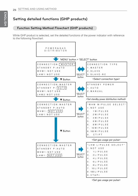
Setting detailed functions (GHP products)
Function Setting Method Flowchart (GHP products)
While GHP product is selected, set the detailed functions of the power indicator with referenceto the following flowchart.
C O N N E C T I O N T Y P E
1 . M A S T E R
2 . S L A V E
3 . S L A V E - R C
C O N N E C T I O N : M A S T E R
S T A N D B Y P : A U T O
W H M 1 : N O T U S E
L H M 1 : N O T U S E
C O N N E C T I O N : M A S T E R
S T A N D B Y P : A U T O
W H M 1 : N O T U S E
L H M 2 : N O T U S E
C O N N E C T I O N : M A S T E R
S T A N D B Y P : A U T O
W H M 1 : N O T U S E
L H M 1 : N O T U S E
S T A N D B Y P O W E R
1 . A U T O
2 . M A N U A L
C O N N E C T I O N : M A S T E R
S T A N D B Y P : A U T O
W H M 1 : N O T U S E
L H M 1 : N O T U S E
* W H M W / P U L S E S E L E C T *
1 . N O T U S E
2 . 1 W / P U L S E
3 . 2 W / P U L S E
4 . 4 W / P U L S E
5 . 6 W / P U L S E
6 . 8 W / P U L S E
7 . 10 W / P U L S E
8 . 100 W / P U L S E
9 . C T / P T
* L H M L / P U L S E S E L E C T *
1 . N O T U S E
2 . 1 L / P U L S E
3 . 2 L / P U L S E
4 . 4 L / P U L S E
5 . 6 L / P U L S E
6 . 8 L / P U L S E
7 . 10 L / P U L S E
8 . 100 L / P U L S E
9 . V T & P r
‘MENU’ button + ‘SELECT’ button
<Select connection type>
<Set standby power distribution method>
<Set gas usage per pulse>
<Set gas usage per pulse>
▼ Button
▼ Button
▼ Button
‘SELECT’button
‘SELECT’button
‘SELECT’button
‘SELECT’button
1,MFL67982907,영영 2017. 7. 13. 영영 1:14 Page 26

SETTING AND USING METHOD 27 ENG
LISH
<Select the power consumption device>
<Set CT type>
<Set VT type>
<Set the connected indoor unit address>
<Set the connected indoor unit address>
‘SELECT’button
‘SELECT’ button
‘SELECT’button
‘SELECT’button
‘SELECT’button
‘SELECT’button
‘SELECT’ button
C T & P U L S E R A T I O S E T
C T : 0 0 0 0 0 , P r : 0 0 0 0 0
W H M 1 [ P u l s e / k W h ]
V T & P U L S E R A T I O S E T
V T : 0 0 0 0 0 , P r : 0 0 0 0 0
L H M 1 [ P u l s e / k L ]
C O N S U M E U N I T S E L E C T
1 . O U T D O O R U N I T
2 . I N D O O R U N I T
I N D O O R A D D R E S S S E T
( S T A R T ) → ( E N D )
( 0 0 ) → ( 0 0 )
I N D O O R A D D R E S S S E T
( S T A R T ) → ( E N D )
( 0 0 ) → ( 0 0 )
CAUTION
• Power indicator setting only can be changed during the 20 minutes after turning on thepower.20 minutes later, if you need to change settings, turn the power indicator on again.
!
1,MFL67982907,영영 2017. 7. 13. 영영 1:14 Page 27

28 SETTING AND USING METHOD
ENG
LISH
Setting functions (GHP products)
• Set the properties of the wattmeter and gas meter.- Pulse type: Set power consumption per pulse / gas consumption, mounting location (divide in-door and outdoor unit), and the indoor unit address.
- CT (VT) type: Set CT (VT), the instrument integer value, mounting location (divide indoor andoutdoor unit), and the indoor unit address.
WHM1: Mount the wattmeter.LHM1 : Mount the gas meter.
• When setting the properties of the pulse-type wattmeter (WHM1).
On the Home screen, press the (▼) button and then thescreen is switched to the wattmeter / gas meter propertysetting screen.
When the item of the wattmeter you want to set is blink-ing, press the SELECT button, and the screen will beswitched to the detailed setting screen.
After setting every wattmeter, press the menu button to save the settings and the screen will beswitched to the initial screen.
Set power consumption per pulse ’ set the power consump-tion device ’ set the connected indoor unit address in order.- Set power consumption per pulse (WHM W / PULSE SELECT).: Please enter a value shown in the wattmeter as the powerconsumption recognized per pulse.
- Set the power consumption device (CONSUME UNIT SELECT).: Please set up after making sure that the wattmeter is in-stalled, and checking whether the product installed is theindoor or outdoor unit.※If one indoor unit is set to use both outdoor unit power dis-
tribution and indoor unit power distribution, wattage value isdisplayed as indoor unit wattage value by summing outdoorunit power distribution value and indoor unit power distribu-tion value.
- Set the connected indoor unit address (INDOOR ADDRESS SET).: Enter the address of the indoor unit connected to thewattmeter.※After the initial installation, address setting of indoor unit
connected to each port shall not be changed. If it ischanged, previous data cannot be used.
After setting the item, press the SELECT button to save thesetting, and then move to the next step.
C O N N E C T I O N : M A S T E R
S T A N D B Y P : A U T O
W H M 1 : N O T U S E
L H M 1 : N O T U S E
C O N N E C T I O N : M A S T E R
S T A N D B Y P : A U T O
W H M 1 : N O T U S E
L H M 1 : N O T U S E
* W H M W / P U L S E S E L E C T *
1 . N O T U S E
2 . 1 W / P U L S E
3 . 2 W / P U L S E D O W N
C O N S U M E U N I T S E L E C T
1 . O U T D O O R U N I T
2 . I N D O O R U N I T
I N D O O R A D D R E S S S E T
(START) → (END)
(00) → (00)
C O N N E C T I O N : M A S T E R
S T A N D B Y P : A U T O
W H M 1 : 2 W , O D U , 0 0 - 0 0
L H M 1 : N O T U S E
Configuration information is reflected on thedetailed setting window.
1,MFL67982907,영영 2017. 7. 13. 영영 1:14 Page 28

SETTING AND USING METHOD 29 ENG
LISH
• When setting the properties of the pulse-type gas meter (LHM1)
On the initial setting screen, press the (▼) button andthe screen will be switched to the wattmeter / gasmeter property setting screen.
When the item of the wattmeter you want to set isblinking, press the SELECT button, and the screen willbe switched to the detailed setting screen.
Configuration information is reflected in thedetailed setting window.
Set gas consumption per pulse ’ Set the connected in-door unit address in order.- Set gas consumption per pulse (LHM L / PULSE SELECT).: Please enter a value shown in the gas meter as thegas consumption recognized per pulse.
- Set the connected indoor unit address (INDOOR AD-DRESS SET).: Enter the address of the indoor unit connected to thegas meter.※After the initial installation, address setting of indoor
unit connected to each port shall not be changed. Ifit is changed, previous data cannot be used.
- Set connected indoor address (INDOOR ADDRESS SET): Enter the indoor address connected to applicablewattmeter.
After setting the item, press the SELECT button to savethe settings, and then move to the next step.
C O N N E C T I O N : M A S T E R
S T A N D B Y P : A U T O
W H M 1 : N O T U S E
L H M 1 : N O T U S E
C O N N E C T I O N : M A S T E R
S T A N D B Y P : A U T O
W H M 1 : N O T U S E
L H M 1 : N O T U S E
* L H M L / P U L S E S E L E C T *
1 . N O T U S E
2 . 1 L / P U L S E
3 . 2 L / P U L S E D O W N
I N D O O R A D D R E S S S E T
(START) → (END)
(00) → (00)
C O N N E C T I O N : M A S T E R
S T A N D B Y P : A U T O
W H M 1 : N O T U S E
L H M 1 : 1 0 L , O D U , 0 0 - 0 0
After setting every gas meter, press the menu button to save the settings, and then move to theinitial screen.
1,MFL67982907,영영 2017. 7. 13. 영영 1:14 Page 29

30 SETTING AND USING METHOD
ENG
LISH
• When setting the properties of the CT-type wattmeter (WHM1)
On the initial setting screen, press the (▼) button andthen will be switched to the wattmeter / gas meter prop-erty setting screen.
When the item of the wattmeter you want to set is blink-ing, press the SELECT button, and the screen will beswitched to the detailed setting screen.
On the screen of the power consumption per pulse,press the (▼) button to select the item of CT/PT.
When the item of CT/PT is blinking, press the SELECTbutton, and the screen will be switched to the screenwhere CT&PULSE RATIO SET is entered.
The set information is reflected on the detailed settingwindow.
It proceeds in the order of Set CT, device constant ’ Setpower consumption device ’ Set connected indoor address.- CT, calibrating constant setting (CT&PULSE RATIO SET)
*CT: As the device to reduce the current so that the measuringdevice can take the measurement, enter the rate indicatedon the product to the CT item. Ex) When using 100:1 CT, enter 100 to the CT item.
*Pr: As the device constant value, it is displayed as ratio ofoutput pulse per power consumption of wattmeter. Forthe device constant value, enter the value displayed onwattmeter [Pulse/kWh]Ex) When using 2 500 [Pulse/kWh] wattmeter, enter
2 500 to Pr item.- Power consumption device setting (CONSUME UNIT SELECT): Check whether the product with watt-hour meter installed isoutdoor unit or indoor unit first, and perform the setting.※If one indoor unit is set to use both outdoor unit power distribu-
tion and indoor unit power distribution, wattage value is dis-played as indoor unit wattage value by summing outdoor unitpower distribution value and indoor unit power distribution value.
- Connected indoor unit address setting (INDOOR ADDRESS SET): Input the address of the indoor unit connected to the corre-sponding watt-hour meter.※After the initial installation, address setting of indoor unit
connected to each port shall not be changed. If it ischanged, previous data cannot be used.
After setting the item, press the SELECT button to save the set-tings, and then move to the next step.
C O N N E C T I O N : M A S T E R
S T A N D B Y P : A U T O
W H M 1 : N O T U S E
L H M 1 : N O T U S E
C O N N E C T I O N : M A S T E R
S T A N D B Y P : A U T O
W H M 1 : N O T U S E
L H M 1 : N O T U S E
* W H M W / P U L S E S E L E C T *
1 . N O T U S E
2 . 1 W / P U L S E
3 . 2 W / P U L S E D O W N
* W H M W / P U L S E S E L E C T *
7 . 1 0 W / P U L S E
8 . 1 0 0 W / P U L S E
9 . C T / P T
C T & P U L S E R A T I O S E T
C T : 0 0 0 0 0 , P r : 0 0 0 0 0
W H M 1 [P u l s e / k W h]
C O N S U M E U N I T S E L E C T
1 . O U T D O O R U N I T
2 . I N D O O R U N I T
I N D O O R A D D R E S S S E T
(START) → (END)
(00) → (00)
C O N N E C T I O N : M A S T E R
S T A N D B Y P : A U T O
W H M 1 : C T / P T , I D U , 0 0 - 0 0
L H M 1 : N O T U S E
After setting every Watt-hour meter, press the menu button to save the settings, and then moveto the initial screen.
1,MFL67982907,영영 2017. 7. 13. 영영 1:14 Page 30
SETTING AND USING METHOD 31 ENG
LISH
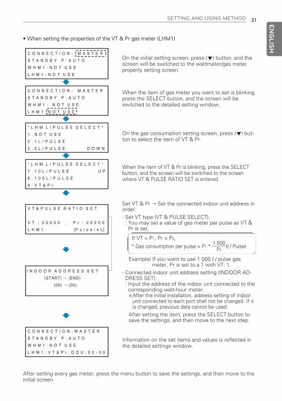
• When setting the properties of the VT & Pr gas meter (LHM1)
On the initial setting screen, press (▼) button, and thescreen will be switched to the wattmeter/gas meterproperty setting screen.
When the item of gas meter you want to set is blinking,press the SELECT button, and the screen will beswitched to the detailed setting window.
On the gas consumption setting screen, press (▼) but-ton to select the item of VT & Pr.
When the item of VT & Pr is blinking, press the SELECTbutton, and the screen will be switched to the screenwhere VT & PULSE RATIO SET is entered.
Information on the set items and values is reflected inthe detailed settings window.
Set VT & Pr ’ Set the connected indoor unit address inorder.- Set VT type (VT & PULSE SELECT).: You may set a value of gas meter per pulse as VT &Pr is set.
Example) If you want to use 1 000 l / pulse gasmeter, Pr is set to a 1 with VT: 1.
- Connected indoor unit address setting (INDOOR AD-DRESS SET): Input the address of the indoor unit connected to thecorresponding watt-hour meter.※After the initial installation, address setting of indoor
unit connected to each port shall not be changed. If itis changed, previous data cannot be used.
After setting the item, press the SELECT button tosave the settings, and then move to the next step.
If VT = P1, Pr = P2,
C O N N E C T I O N : M A S T E R
S T A N D B Y P : A U T O
W H M 1 : N O T U S E
L H M 1 : N O T U S E
C O N N E C T I O N : M A S T E R
S T A N D B Y P : A U T O
W H M 1 : N O T U S E
L H M 1 : N O T U S E
* L H M L / P U L S E S E L E C T *
1 . N O T U S E
2 . 1 L / P U L S E
3 . 2 L / P U L S E D O W N
* L H M L / P U L S E S E L E C T *
7 . 1 0 L / P U L S E U P
8 . 1 0 0 L / P U L S E
9 . V T & P r
V T & P U L S E R A T I O S E T
V T : 0 0 0 0 0 , P r : 0 0 0 0 0
L H M 1 [P u l s e / k L]
I N D O O R A D D R E S S S E T
(START) → (END)
(00) → (00)
C O N N E C T I O N : M A S T E R
S T A N D B Y P : A U T O
W H M 1 : N O T U S E
L H M 1 : V T & P r , O D U , 0 0 - 0 0
After setting every gas meter, press the menu button to save the settings, and then move to theinitial screen.
* Gas consumption per pulse = P1 * (l / Pulse)1 000
P2
1,MFL67982907,영영 2017. 7. 13. 영영 1:14 Page 31
32 SETTING AND USING METHOD
ENG
LISH
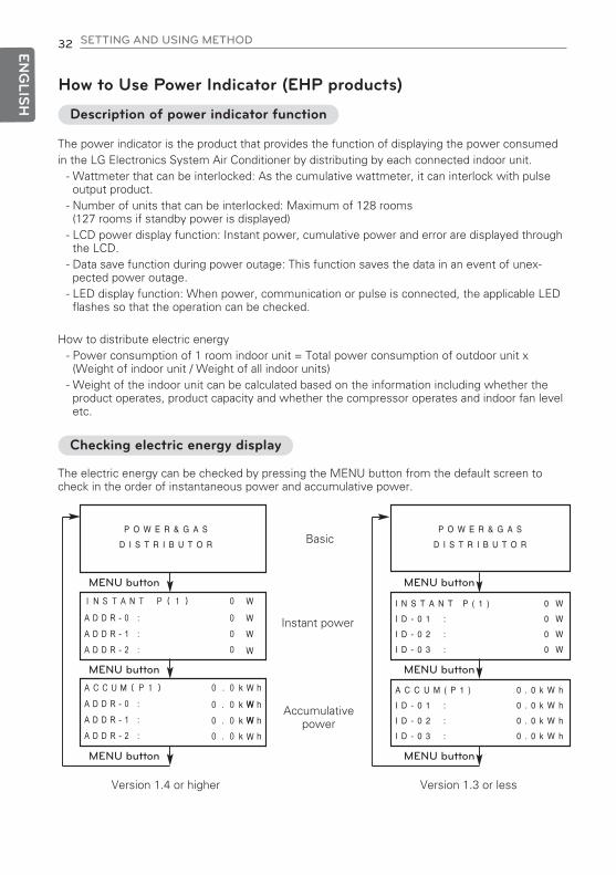
How to Use Power Indicator (EHP products)
Description of power indicator function
Checking electric energy display
The power indicator is the product that provides the function of displaying the power consumedin the LG Electronics System Air Conditioner by distributing by each connected indoor unit.
- Wattmeter that can be interlocked: As the cumulative wattmeter, it can interlock with pulseoutput product.
- Number of units that can be interlocked: Maximum of 128 rooms(127 rooms if standby power is displayed)
- LCD power display function: Instant power, cumulative power and error are displayed throughthe LCD.
- Data save function during power outage: This function saves the data in an event of unex-pected power outage.
- LED display function: When power, communication or pulse is connected, the applicable LEDflashes so that the operation can be checked.
How to distribute electric energy- Power consumption of 1 room indoor unit = Total power consumption of outdoor unit x(Weight of indoor unit / Weight of all indoor units)
- Weight of the indoor unit can be calculated based on the information including whether theproduct operates, product capacity and whether the compressor operates and indoor fan leveletc.
The electric energy can be checked by pressing the MENU button from the default screen tocheck in the order of instantaneous power and accumulative power.
MENU button
MENU button
MENU button
MENU button
MENU button
MENU button
I N S T A N T P ( 1 )
I D - 0 1 :
I D - 0 2 :
I D - 0 3 :
0 W
0 W
0 W
0 W
A C C U M ( P 1 )
I D - 0 1 :
I D - 0 2 :
I D - 0 3 :
0 . 0 k W h
0 . 0 k W h
0 . 0 k W h
0 . 0 k W h
P O W E R & G A S
D I S T R I B U T O R
P O W E R & G A S
D I S T R I B U T O R
A D D R - 0 :A D D R - 1 :A D D R - 2 :
A D D R - 0 :A D D R - 1 :A D D R - 2 :
Basic
Instant power
Accumulativepower
Version 1.4 or higher Version 1.3 or less
1,MFL67982907,영영 2017. 7. 13. 영영 1:14 Page 32
SETTING AND USING METHOD 33 ENG
LISH
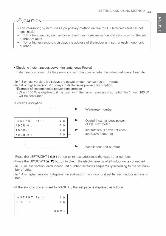
• Checking instantaneous power (Instantaneous Power)
Instantaneous power: As the power consumption per minute, it is refreshed every 1 minute.
- In 1.3 or less version, it displays the power amount consumed in 1 minute.- In 1.4 or higher version, it displays instantaneous power consumption.*Example of instantaneous power consumption: When 100 W is displayed, if it is used with the current power consumption for 1 hour, 100 Whwill be consumed.
- Screen Description
- Press the LEFT/RIGHT (◀,▶) button to increase/decrease the wattmeter number.
- Press the UP/DOWN (s,t) button to check the electric energy of all indoor units connected.
- In 1.3 or less version, each indoor unit number increases sequentially according to the set num-ber of units.
- In 1.4 or higher version, it displays the address of the indoor unit set for each indoor unit num-ber.
- If the standby power is set to MANUAL, the last page is displayed as follows.
Wattmeter number
Each indoor unit number
Overall instantaneous powerof P(1) wattmeter
Instantaneous power of eachapplicable indoor unit
I N S T A N T P ( 1 )
A D D R - 0 :A D D R - 1 :A D D R - 2 :
0 W
0 W
0 W
0 W
I N S T A N T P ( 1 )
S T B P :
0 W
0 W
D O W N
CAUTION
• This measuring system uses a proprietary method unique to LG Electronics and has notlegal basis.
• In 1.3 or less version, each indoor unit number increases sequentially according to the setnumber of units.
• In 1.4 or higher version, it displays the address of the indoor unit set for each indoor unitnumber
!
1,MFL67982907,영영 2017. 7. 13. 영영 1:14 Page 33

34 SETTING AND USING METHOD
ENG
LISH
• Checking accumulative power
Accumulative power: After the power is initially connected to the power indicator, the valuesare accumulated.
If the displayed electric energy is 999 999 or above, it will return to 0.
• Screen Description
- Press the LEFT/RIGHT (◀,▶) button to increase/decrease the wattmeter number.
- Press the UP/DOWN (s,t) button to check the electric energy of all indoor units connected.
- In 1.3 or less version, each indoor unit number increases sequentially according to the set num-ber of units.
- In 1.4 or higher version, it displays the address of the indoor unit set for each indoor unit number.
- If the standby power is set to MANUAL, the last page is displayed as follows.
- In 1.4 or higher version, if you press left/right button(◀,▶), it is displayed as follows in the lastpage. You can check the entire indoor units’ accumulated power for each address in this screen.
Wattmeter number
Each indoor unit number
Overall accumulated powerof P(1) wattmeter
Accumulated power of eachapplicable indoor unit
A C C U M ( P 1 )
A D D R - 0 :
A D D R - 1 :
A D D R - 2 :
0 . 0 k W h
0 . 0 k W h
0 . 0 k W h
0 . 0 k W h
A C C U M ( P 1 )
S T B P :
0 . 0 k W h
0 . 0 k W h
D O W N
A C C U M ( A L L )
0 . 0 k W h
0 . 0 k W h
0 . 0 k W h
A D D R - 0 :
A D D R - 1 :
A D D R - 2 :
CAUTION
• According to watt-hour meter and PDI installation time, the final accumulated value dis-played by each may be different.
• During the ACP/Smart interface, if you set the e-mail, e-mail alarm is sent when wattagedistribution cannot be made by special conditions.
• PDI accumulated power value is not initialized.
• When you change the indoor unit address, you can check the accumulated power amountof each indoor unit address that is not set to each port in ACCUM(ALL) screen.
!
1,MFL67982907,영영 2017. 7. 13. 영영 1:14 Page 34

SETTING AND USING METHOD 35 ENG
LISH
How to Use the Power Indicator (GHP products)
Description of the Power Indicator Function
Checking electric energy and gas consumption display
The power indicator is a product that provides the function of displaying the power consumed inthe LG Electronics System Air Conditioner distributed to each connected indoor unit.
- Wattmeter that can be interlocked: As the cumulative wattmeter, it can interlock with pulseoutput product.
- Gas meter that can be interlocked: As the cumulative gas meter, it can interlock with pulseoutput product.
- Number of indoor units that can be interlocked: Maximum of 64 units- LCD display function: Instant power/cumulative power and instant gas/cumulative gas anderror are displayed through the LCD.
- Data save function during power outage: This function saves the data in an event of unex-pected power outage.
- LED display function: When power, communication or pulse is connected, the applicable LEDblinks so that the operation can be checked.
How to distribute electric energy or gas usage- Power consumption of 1 room indoor unit(gas) = Total power consumption of outdoorunit(gas) x (Weight of indoor unit / Weight of all indoor units)
- Weight of each indoor unit can be calculated based on the information including whether the prod-uct operates, product capacity and whether the compressor operates and indoor fan level, etc.
The electric energy and gas consumption can be checked by pressing the MENU button from thedefault screen to check in the order of instantaneous power and accumulative power.On the screen of instantaneous power, accumulative power, press the (►) button to check theinstantaneous gas, and accumulative gas.
MENU button
MENU button
Basic
button
button
MENU button MENU buttonInstantaneous power
accumulative power
Instantaneous gas
Accumulative Gas
I N S T A N T P ( 1 )
A D D R - 0 :A D D R - 1 :A D D R - 2 :
0 W
0 W
0 W
0 W
A C C U M ( P 1 )
A D D R - 0 :A D D R - 1 :A D D R - 2 :
0 . 0 k W h
0 . 0 k W h
0 . 0 k W h
0 . 0 k W h
I N S T A N T G ( 1 )
A D D R - 0 :A D D R - 1 :A D D R - 2 :
0 L
0 L
0 L
0 L
A C C U M ( G 1 )
A D D R - 0 :A D D R - 1 :A D D R - 2 :
0 . 0 k L
0 . 0 k L
0 . 0 k L
0 . 0 k L
P O W E R & G A S
D I S T R I B U T O R
CAUTION
• This measuring system uses a proprietary method unique to LG Electronics without legal basis.
!
1,MFL67982907,영영 2017. 7. 13. 영영 1:14 Page 35

36 SETTING AND USING METHOD
ENG
LISH
• Checking the instantaneous power
Instantaneous power: It is the power consumption value for one minute which is updated every1 minute.
- In 1.3 or less version, it displays the power amount consumed in 1 minute.- In 1.4 or higher version, it displays instantaneous power consumption.*Example of instantaneous power consumption: When 100 W is displayed, if it is used with the current power consumption for 1 hour, 100 Whwill be consumed.
- Screen Description
- Press the LEFT/RIGHT (◀,▶) button to increase/decrease the wattmeter meter number.- Press the UP/DOWN (s,t) button to check the electric energy of all indoor units connected.- In 1.3 or less version, each indoor unit number increases sequentially according to the set number of units.- In 1.4 or higher version, it displays the address of the indoor unit set for each indoor unit number.
- When you set Standby power to MANUAL, the last page will display as below.
Wattmeter number (P1)
Each indoor unit No.
Total instantaneous powerat P (1) wattmeter
The instantaneous power of eachindoor unit
I N S T A N T P ( 1 )
A D D R - 0 :A D D R - 1 :A D D R - 2 :
0 W
0 W
0 W
0 W
• Confirming the instantaneous gas consumption (Instantaneous Gas)
Instantaneous gas: It is a gas consumption value for 1 minute which is refreshed every 1 minute.
- Screen Description
- Press the LEFT/RIGHT (◀,▶) button to increase/decrease the gas meter number.- Press the UP/DOWN (s,t) button to check the gas energy of all indoor units connected.- In 1.3 or less version, each indoor unit number increases sequentially according to the set number ofunits.
- In 1.4 or higher version, it displays the address of the indoor unit set for each indoor unit number.h In the case of gas on, standby gas usage is not displayed separately because there is no standby
gas.
Gas meter No. (G1)
Each indoor unit No.
G(1): Total instant gas consumptionin the gas meter
Instant gas consumption ineach indoor unit
I N S T A N T G ( 1 )
A D D R - 0 :A D D R - 1 :A D D R - 2 :
0 L
0 L
0 L
0 L
I N S T A N T P ( 1 )
S T B P
0 W
0 W
D O W N
1,MFL67982907,영영 2017. 7. 13. 영영 1:14 Page 36

SETTING AND USING METHOD 37 ENG
LISH
• Checking the accumulative power (Accum Power)
Accumulative power: Values have been continuously accumulated since the initial power is ap-plied on the power indicator. When wattage is more than 999 999, it will return to “0”.
- Screen Description
- Press the LEFT/RIGHT (◀,▶) button to increase/decrease the wattmeter number.- Press the UP/DOWN (s,t) button to check the electric energy of all indoor units connected.- In 1.3 or less version, each indoor unit number increases sequentially according to the set number of units.- In 1.4 or higher version, it displays the address of the indoor unit set for each indoor unit number.
- If the standby power is set to MANUAL, the last page is displayed as follows.
A C C U M ( P 1 )
A D D R - 0 :A D D R - 1 :A D D R - 2 :
0 . 0 k W h
0 . 0 k W h
0 . 0 k W h
0 . 0 k W h
• Checking the accumulative gas consumption (Accumulative Gas)Instant gas: Values have been accumulated since the initial power is applied at the gas meter.When the displayed gas usage is more than 999 999, it will return to “0”.
- Screen Description
- Press the LEFT/RIGHT (◀,▶) button to increase/decrease the wattmeter number.- Press the UP/DOWN (s,t) button to check the gas energy of all indoor units connected.- In 1.3 or less version, each indoor unit number increases sequentially according to the set number of units.- In 1.4 or higher version, it displays the address of the indoor unit set for each indoor unit number.h In the case of gas on, standby gas usage is not displayed separately because there is no
standby gas.
Gas meter No.
Each indoor unit No.
Total accumulative gas usageat G (1) gas meter
The accumulative gas usage ofeach indoor unit
A C C U M ( G 1 )
A D D R - 0 :A D D R - 1 :A D D R - 2 :
0 . 0 k L
0 . 0 k L
0 . 0 k L
0 . 0 k L
A C C U M ( P 1 )
S T B P :
0 . 0 k W h
0 . 0 k W h
D O W N
- In 1.4 or higher version, if you press left/right button(◀,▶), it is displayed as follows in the last page. In this screen, you can check the accumulated power amount (gas usage amount) of each addressfor the entire indoor units.
A C C U M ( A L L )
0 . 0 k W h
0 . 0 k W h
0 . 0 k W h
A D D R - 0 :
A D D R - 1 :
A D D R - 2 :
Wattmeter number
Each indoor unit No.
Total accumulative wattage at P (1) wattmeter
The accumulative wattage of eachindoor unit
1,MFL67982907,영영 2017. 7. 13. 영영 1:14 Page 37

38 SETTING AND USING METHOD
ENG
LISH
If the communication with the air conditioner is not smooth or if the pulse signal is not detectedfrom the wattmeter, the error will be displayed on the LCD.
• Communication error display
- If there is no communication with the indoor unit product for 3 minutes, it displays an error.
- During communication error status, power consumption (gas consumption) is reflected on theaccumulative power (accumulative gas).
- No power(gas) is distributed to each indoor unit. When communication is resumed, accumula-tive power (gas) is distributed to each indoor unit.
• No signal error in the wattmeter (gas meter)
- Error is displayed when there is no signal from the pulse detection in the option-set wattmeter(gas meter) (When no pulse is detected even when 1 or more unit doors are operating)
Error display
E R R O R - 0 1
N O C O M M U N I C A T I O N
W I T H A I R C O N D I T I O N E R
I D U A D D R E S S [ 0 0 - 0 7 ]
E R R O R - 0 2
N O S I G N A L F R O M W H M 1
CAUTION
• In the case of no signal error in the wattmeter (gas meter)As outdoor unit power consumption (gas consumption) is low, if no pulse is displayed for acertain time, error may be displayed. As soon as pulse is applied, error indication disap-pears.
!
CAUTION• According to watt-hour meter/gas meter and PDI installation time, the final accumulated
value displayed by each may be different.• During the ACP/Smart interface, if you set the e-mail, e-mail alarm is sent when wattage
and gas usage amount distribution cannot be made by special conditions.• PDI accumulated power value and accumulated gas usage value are not initialized.• When you change the indoor unit address, you can check the accumulated power amount
(gas usage amount) of each indoor unit address that is not set to each port in ACCUM(ALL)screen.
!
1,MFL67982907,영영 2017. 7. 13. 영영 1:14 Page 38

SETTING AND USING METHOD 39 ENG
LISH
Operating condition display
LED condition display
- Power LED (Red): When on, it shows that the product is in operation.
- Communication LED (Green, Yellow)
: Central controller, 485 communication condition are displayed.Green LED ON: Signal sentYellow LED ON: Signal received
- The wattmeter (gas meter) receives pulse (yellow): The connected wattmeter (gas meter) dis-plays the pulse signal reception status. When pulse signal is input, the LED blinks (once per pulse).
- When the power is connected initially, all LEDs are turned on.
- If the pulse signal receipt condition display LED is continuously ON, it could mean that there is ashort circuit between the two terminals. Please check.
(If you are using a mechanical gas meter, depending on when operation is stopped, the LED maybe on sometimes.)
Pulse signal receipt condition
485 communication condition
POWER WHM
PPWRDB000
ODU
MENU
SELECT
WHM CHECK
1,MFL67982907,영영 2017. 7. 13. 영영 1:14 Page 39

40ENG
LISH
1,MFL67982907,영영 2017. 7. 13. 영영 1:14 Page 40

Ver 1.0.6
[Representative] LG Electronics Inc. EU Representative Krijgsman 1, 1186 DM Amstelveen, The Netherlands
[Manufacturer] LG Electronics Inc. Changwon 2nd factory 84, Wanam-ro, Seongsan-gu, Changwon-si, Gyeongsangnam-do, KOREA
1,MFL67982907,영영 2017. 7. 6. 영영 4:58 Page 100