installation, operation rogramming...
TRANSCRIPT

ECN 98-520
INSTALLATION, OPERATION, AND
PROGRAMMING MANUAL
NOTI�FIRE�NET� is a trademark of NOTIFIER, 1994.
DOCUMENT NUMBER 1509012/21/98 REVISION H
Technical Manuals Online! - http://www.tech-man.com

Network Reporting Terminal 15090:H 12/21/982
Technical Manuals Online! - http://www.tech-man.com

Network Reporting Terminal 15090:H 12/21/98 3
Table of ContentsCHAPTER ONE INSTALLATION....................................................................................... 5
Section One NRT Mounting and Connections ........................................................................................... 61.1 RELATED DOCUMENTATION ............................................................................................................................................... 61.2 NRT-NET INTERFACE CARD ................................................................................................................................................. 71.3 NRT EQUIPMENT .................................................................................................................................................................... 71.4 PRIMARY AND SECONDARY POWER ............................................................................................................................... 71.5 CONNECTING THE NRT-586T ............................................................................................................................................... 81.6 MONITOR INSTALLATION .................................................................................................................................................. 101.7 NRT UPS SUPERVISION ....................................................................................................................................................... 121.8 STRAIN RELIEF ..................................................................................................................................................................... 14
Section Two Peripherals ........................................................................................................................... 152.1 CONNECTING A PRINTER ................................................................................................................................................... 15
Section Three Software ............................................................................................................................. 163.1 INSTALLING THE NRT DATABASE SYSTEM .................................................................................................................. 163.2 INSTALLING THE NRT SOFTWARE ................................................................................................................................... 173.3 INSTALLING THE LANDesk CLIENT SERVER ................................................................................................................. 173.4 INSTALLED PRINTERS ......................................................................................................................................................... 173.5 INSTALLED LIGHT PEN (LP-2) ........................................................................................................................................... 183.6 MAGNETIC TAPE BACKUP ................................................................................................................................................. 18
CHAPTER TWO PROGRAMMING ................................................................................... 19
Section One Networking the NRT ............................................................................................................. 20
Section Two User Interface ....................................................................................................................... 212.1 THE SCREEN ........................................................................................................................................................................... 212.2 USING THE MOUSE AND KEYBOARD ............................................................................................................................ 22
Section Three The Start-up Window ......................................................................................................... 233.1 FILE MENU ............................................................................................................................................................................. 233.2 ADMINISTRATIVE MENU ................................................................................................................................................... 263.3 THE ACTION MENU .............................................................................................................................................................. 283.4 THE WINDOW MENU ........................................................................................................................................................... 293.5 THE HELP MENU ................................................................................................................................................................... 29
Section Four The System Interface Window ............................................................................................ 304.1 THE SELECT SYSTEM DIALOG BOX ................................................................................................................................ 314.2 NODE DIALOG BOXES ........................................................................................................................................................ 34
Section Five The Active/Stored History Window ..................................................................................... 425.1 CHANGING THE ACTIVE HISTORY BUFFER ................................................................................................................. 435.2 CHANGING THE STORED HISTORY FILE ....................................................................................................................... 435.3 PRINTING THE ACTIVE/STORED HISTORY WINDOW ................................................................................................. 435.4 THE GRAPHIC HISTORY WINDOW .................................................................................................................................. 45
Section Six The Memo Window ................................................................................................................ 46
Section Seven The Upload/Download Window........................................................................................ 477.1 UPLOAD .................................................................................................................................................................................. 487.2 SCHEDULE UPLOAD ............................................................................................................................................................ 487.3 DOWNLOAD ........................................................................................................................................................................... 497.4 ABORT ...................................................................................................................................................................................... 49
Section Eight The Graphic Presentation Window ................................................................................... 508.1 APPLYING ATTRIBUTES TO A CAD FILE ......................................................................................................................... 508.1.1 THE AFP-300/AFP-400 ....................................................................................................................................................... 508.2 PROGRAMMING THE NRT .................................................................................................................................................. 51
Technical Manuals Online! - http://www.tech-man.com

Network Reporting Terminal 15090:H 12/21/984
8.3 CUSTOMIZING THE GRAPHIC ICONS ............................................................................................................................. 54
8.4 SETTING UP THE ZOOM FEATURE ................................................................................................................................... 568.5 AUTOMATIC SCREEN VECTORING .................................................................................................................................. 56
CHAPTER THREE OPERATION ..................................................................................... 57
Section One Normal Operation ................................................................................................................ 58
Section Two Fire Alarms ........................................................................................................................... 592.1 FIRE ALARMS ........................................................................................................................................................................ 592.2 ACKNOWLEDGING ONE OR MORE FIRE ALARMS ...................................................................................................... 59
Section Three Troubles ............................................................................................................................... 613.1 TROUBLES WITH ADDRESSABLE DEVICES .................................................................................................................. 613.2 TROUBLES WITH SECURITY DEVICES ........................................................................................................................... 623.3 TROUBLES WITH SUPERVISORY DEVICES ................................................................................................................... 633.4 TROUBLES WITH DISABLED ZONES ............................................................................................................................... 643.5 TROUBLES WITH THE AM2020/AFP1010 SYSTEMS ...................................................................................................... 643.6 TROUBLES WITH ANNUNCIATORS ................................................................................................................................. 653.7 TROUBLES WITH AFP-300/AFP-400 BELL CIRCUITS .................................................................................................... 653.8 TROUBLES WITH AFP300/AFP-400 PANEL CIRCUITS .................................................................................................. 663.9 ACKNOWLEDGING TROUBLES ......................................................................................................................................... 673.9.1 TROUBLE WITH NRT AND INA EQUIPMENT .............................................................................................................. 673.9.2 DEVICE MESSAGE TRANSLATIONS for the AFP-300/400 AND AFP-200 ................................................................. 67
Section Four Read Status ......................................................................................................................... 75
Section Five The Graphic Presentation Window ..................................................................................... 795.1 ACCESSING INFORMATION ABOUT DEVICES ............................................................................................................. 80
APPENDIX A WINDOWS NT® SECURITY DISABLE PROCEDURE ............................. 81
APPENDIX B WINDOWS NT® 4.0 INSTALLATION ......................................................... 82
Technical Manuals Online! - http://www.tech-man.com

Network Reporting Terminal 15090:H 12/21/98 5
CHAPTER ONE
INSTALLATION
NETWORK REPORTING TERMINAL
(NRT)
Technical Manuals Online! - http://www.tech-man.com

Network Reporting Terminal 15090:H 12/21/986
SECTION ONE
NRT MOUNTING AND CONNECTIONSThe Network Reporting Terminal (NRT) is a listed computer with VGA graphics for displaying all network events. TheNRT is used with the Notifier NOTI�FIRE�NET� system. One model of the NRT is available; the NRT-586T, ahigh-performance tower style computer.
1.1 RELATED DOCUMENTATIONTo obtain a complete understanding of the NRT features and related products or to become familiar with functions ingeneral, make use of the documentation noted in Table 1.1-1. The Notifier document chart (DOC-NOT) provides thecurrent document revision. A copy of this document is included with each shipment of Notifier products.
Table 1.1-1 Related Documentation
ELTIT REBMUN ELTIT REBMUN
F0101PFA/0202MA IRE ALARM CONTROL
PANEL88051 ANNUNCIATOR CONTROL SYSTEM 24851
LIQUID CRYSTAL DISPLAY )08-DCL( 73051 LAMP DRIVER MODULES )MDL( 58851
NETWORK REPORTING TERMINAL )TRN( 09051 VOICE ALARM MULTIPLEX 98851
INTELLIGENT NETWORK ANNUNCIATOR )ANI( 29051 THE SPX ERIES TRANSPONDER SYSTEM 88851
UNIVERSAL ZONE CODER INSTALLATION
)652-CZU( 61251 NETWORK ADAPTOR MODULE )232-MAN( 83005
PRODUCT INSTALLATION DOCUMENT )1-MCC( 82351 THE UTCADU NIVERSAL DIGITAL ALARM
COMMUNICATOR T/ RANSMITTER05005
PRODUCT INSTALLATION DOCUMENT )RT-SPM( 13351FE42-SPCF/42-SPCF IELD
CHARGER P/ OWER SUPPLY INSTALLATION,OPERATION AND APPLICATION MANUAL
95005
O0101PFA/0202MA PERATOR INSTRUCTIONS 73351 VIDEO GRAPHICS ANNUNCIATOR SYSTEM
I)SAGV( NSTALLATION MANUAL15205
NOTIFIER DEVICE COMPATIBILITY DOCUMENT 87351 MEDIA INTERFACE BOARD )BIM( 55205
ANALOG FIRE PANEL )002-PFA( 11551 REPEATER )TPR( 65205
CANADIAN REQUIREMENTS FOR THE
0101PFA/0202MA 13651 TEN-ERIF-ITON MT 75205
NETWORK INTERFACE BOARD )69-BIN( 66651 TELEPHONE P/ ANEL INTERFACE )232-IPT( 27305
SMOKE CONTROL MANUAL 21751 srednopsnarTseireS5PX 68705
ANALOG FIRE PANEL )004-PFA/003-PFA( /95205/3520506205
AUTOMATIC FIRE ALARM
WARDEN STATION SERIES
PRODUCT INSTALLATION DRAWING
50705
42-54RN CHARGER 06751 I2-XMM NSTALLATION INSTRUCTIONS 00-30-005M
99/12/21lbt.scodnlla
Technical Manuals Online! - http://www.tech-man.com

Network Reporting Terminal 15090:H 12/21/98 7
1.4 PRIMARY AND SECONDARY POWERThe NRT requires primary AC power. Connection to the light and power service must be on a dedicated branch circuit, whichmust be labeled "Fire Alarm Circuit Control" at the circuit switch. The wiring for this circuit must be installed in conduit.Access to the switch must be limited to authorized personnel and the location of the switch must be identified on the PCLB-5power cord locking bracket on the computer. Nothing but fire alarm equipment can be powered from the fire alarm circuit.The primary AC circuit wire run must run continuously, without disconnect devices, from the power source to the NRT.Overcurrent protection for this circuit must comply with Article 760 of the National Electrical Code as well as local codes.Where an NRT is required, the use of a supervised UPS listed for fire protective signaling is also required. When using a UPS,NRT input voltage must be 115 VAC. The use of 230 VAC is not permitted when employing a UPS.
Table 1.3-1 NRT Equipment Options
T685-TRN
)WT685-TRN(knilataderiwTRNCAV032/511
)FT685-TRN(knilcitporebifTRNCAV032/511
)FWT685-TRN(knilataderiw/citporebifTRNCAV032/511
rotinom)mm8.134(hcni-71)B71-NOM(CAV042/511
rotinom)mm4.335(hcni-12)12-NOM(CAV042/511
)2-PL(ecivedgnitniopnepthgiL
1.2 NRT-NET INTERFACE CARDThe NRT communicates with NOTI�FIRE�NET�NOTI�FIRE�NET�NOTI�FIRE�NET�NOTI�FIRE�NET�NOTI�FIRE�NET� through the Network interface card (NRT-NET) and the MediaInterface Board (MIB). The NRT-NET interface card plugs directly into a computer expansion slot located on the NRTcomputer. The MIB, which supports the physical connection to the network, plugs onto the NRT-NET card to com-plete the network interface. The NRT-NET interface card provides the following features:
• Allows the NRT computer to communicate on NOTI�FIRE�NET�NOTI�FIRE�NET�NOTI�FIRE�NET�NOTI�FIRE�NET�NOTI�FIRE�NET�• Accepts the following choices of Media Interface Boards:
- twisted-pair wire cable (MIB-W)- fiber optic wire cable (MIB-F)- twisted pair and fiber optic (MIB-WF)
1.3 NRT EQUIPMENTThe NRT computer has separate options available for use with this model. The equipment listed in Table 1.3-1 maybe used with the NRT computer system it accompanies. The monitor, printer, and mouse must be installed in thesame room as the NRT in order to comply with UL listing requirements.
Technical Manuals Online! - http://www.tech-man.com

Network Reporting Terminal 15090:H 12/21/988
1.5.1 Connecting the NRT-586TThe following steps must be completed when connecting the NRT-586T (refer to Figures 1.5.1-1 and 1.5.1-2).
1. Cut off the plug end of the computer power cord.
2. Plug the socket end of the power cord into the computer.
3. Remove the screws from around the power supply of the NRT-586T (refer to Figure 1.5.1-1).4. Attach the PCLB-5 enclosure without the cover to the back of the NRT-586T using these screws. (refer to
Figure 1.5.1-2).5. Install a 3/4-inch (19.05 mm) conduit and fitting in the knock-out hole of the Power Cord Locking Bracket
cover. Refer to Figure 1.5.1-2.CAUTION: Size the 3/4-inch (19.05 mm) conduit so the line cord can reach a junction box at the other end of theconduit.
6. Thread the power cord through the cover and conduit.
7. Attach the PCLB-5 cover to the PCLB-5 using the mounting screws supplied. Ensure that the PCLB-5 coverholds the power cord socket firmly in place (refer to Figure 1.5.1-2).
8. Connect the power cord to the HSP-121B power line protector as shown in Figure 1.5.1-3. Note: The HSP-121B power line protector must reside in a junction box.
9. Connect 115 VAC, 50/60 Hz primary power or 230 VAC, 50/60 Hz primary power to the HSP-121B as shownin Figure 1.5.1-3. Primary power connected to the HSP-121B (115 VAC or 230 VAC) depends upon theposition of the voltage selection switch shown in Figures 1.5.1-1 and 1.5.1-2 . All wiring must remain inconduit.
WARNING : Improper voltage selection can damage the NRT and void the warranty on the back cover of thismanual.
10. Turn power switch on for the circuit.
11. Connect the monitor to the display adapter video connector on the back of the computer (refer to Figure 1.5.1-1). Connectthe other end of the video cable to the monitor. The video cable is provided with screws for secure attachment.
12. Align the keyboard cable plug to mate with the notch in the computer's jack and insert cable.
13. Connect the mouse to the mouse port at the back of the NRT-586T.
14. Refer to Figure 1.6-1 for monitor power application.
1.5 CONNECTING THE NRT-586T
Figure 1.5.1-1 NRT-586T Connections
PowerCord
COM 2 Port
Remove these screws and reuse for mounting the PCLB-5 plate
Parallel PrinterPort
COM 1 Port
Keyboard
Mouse Port
VoltageSelectionSwitch
Video
Technical Manuals Online! - http://www.tech-man.com

Network Reporting Terminal 15090:H 12/21/98 9
NOTES• The NRT-586T requires 115 VAC, 50/60Hz primary power or 230 VAC, 50/60 Hz primary power
depending upon the position of the voltage selection switch shown in Figures 1.5.1-1 and 1.5.1-2.• Where an NRT is required, the use of a supervised Uninterruptable Power Supply (UPS) is also required
(see Figure 1.7-1)• The NRT is not suitable for use as a receiving unit.• The front power switch for the NRT-586T has been permanently fixed in the ON position.
Figure 1.5.1-2 Attaching the PCLB-5 to the NRT-586T
Voltage SelectionSwitch
Power Cord
To 115 VAC, 50/60Hz Primary Poweror 230 VAC, 50/60Hz Primary Power
AC - Black
Neutral - White
White
Green
Black HSP-121B
Junction Box
Conduit
Figure 1.5.1-3 Connecting the Power Cord and Primary AC Powerto the 46097 Power Line Protector
Ground - Green
Power Cord
Fuse
PCLB-5
Knockout
Mounting Screws
PCLB-5 Cover
Mounting Screw
PCLB-5(without cover)
Technical Manuals Online! - http://www.tech-man.com

Network Reporting Terminal 15090:H 12/21/9810
1.6 MONITOR INSTALLATION1.6.1 Installing the MON-17B/MON-21The following steps must be completed when connecting the MON-17B/MON-21 to the Junction Box and NRT-586T (referto Figure 1.6.1-1).
1. Connect the AC Power Cord on the MON-17B/MON-21 to the HSP-121B Junction Box.
2. Connect the DB-15 video cable to the video card slot on the NRT-586T.
Figure 1.6-1 Installation of MON-17B/MON-21
To 115 VAC, 50/60
Hz Primary Power
or 230 VAC, 50/60
Hz Primary Power
DB-15 Cable
MON-17B/MON-21
NRT-586T
Note: The NRT CPU and the monitor connectionsmay be made on the same HSP-121B: a separateHSP-121B unit for each is not required.
Technical Manuals Online! - http://www.tech-man.com

Network Reporting Terminal 15090:H 12/21/98 11
1.6.2 Connecting a Monitor with the LP-2 Option to the NRT-586TThe following steps must be completed prior to connecting a monitor with the LP-2 option:
1. Connect the video tap to the VGA connector on the back of the NRT-586T (refer to Figure 1.6.2-1).2. Connect the monitor SVGA cable (MON-17B/MON-21) to the video tap.3. Attach the SYNC cable on the video tap to the SYNC input on the LP-2 option.4. Connect the light pen cable to the PEN input on the LP-2 option.
Figure 1.6.2-1 Connecting the Monitor with the LP-2 Option Board
Technical Manuals Online! - http://www.tech-man.com

Network Reporting Terminal 15090:H 12/21/9812
Figure 1.7-1 NRT Computer UPS Supervision
1.7 NRT UPS SUPERVISION1.7.1 NRT Computer/Monitor/Printer UPS SupervisionWhere a Network Reporting Terminal (NRT) is not ancillary, the use of a supervised 115 VAC Uninterruptable Power Supply(UPS) is required. Refer to Figures 1.7-1 and 1.7-2 for wiring information. A networked AM2020/AFP1010 or INA with anMPS-24A Power Supply must be located within three feet (.9144 m) of the UPS and wiring must be in conduit.
Use cable P/N 71033 fromMPS-24A connector P5 toUPS. Cut and strip wiresas needed. Make allconnections in conduit.
Technical Manuals Online! - http://www.tech-man.com

Network Reporting Terminal 15090:H 12/21/98 13
1.7.2 NRT Printer (only) UPS Supervision
Figure 1.7-2 NRT Printer UPS Supervision
Technical Manuals Online! - http://www.tech-man.com

Network Reporting Terminal 15090:H 12/21/9814
1.8 STRAIN RELIEFStrain relief for wiring attached to the NRT wire terminals on the MIB-W and the MIB-WF is provided by a protectivecover (P/N 08275). The protective cover is supplied with both the MIB-W and the MIB-WF.
The following steps must be completed to connect the protective cover with strain relief:
1. Feed wires to be connected to the terminal block through the back or side access hole of the protective cover.The hinged covers of the unused access hole can be closed.
2. Attach the wires to the pluggable terminal block.
3. Snap the strain relief assembly over the pluggable terminal block. Use tie wrap to secure the wires to the protec-tive cover (refer to Figure 1.8-1).
Protective Cover(P/N 08275)
Tie Wrap Around Wire and Hinged Cover
Figure 1.8-1 Strain Relief Assembly
Wiring Access Holesand Hinged Covers
Strain Relief Assembly(snaps over pluggable terminal block)
Cable Restraint(add after assembly)
Technical Manuals Online! - http://www.tech-man.com

Network Reporting Terminal 15090:H 12/21/98 15
SECTION TWO PERIPHERALS
2.1 CONNECTING A PRINTERA printer can be connected to the NRT to print fire alarm and trouble signals (refer to Figure 2.1-1 and Table 2.1-1).
Figure 2.1-1 Serial Port Connections for a Printer connected to NRT-586T
NRTDB9
PrinterDB25
2 2
3 3
5 7
4 and 6jumperedtogether
8 20
Table 2.1-1 Printer ConnectionsNOTES
• Only one NRT (including keyboard, mouse, monitor, or any one of these) can be present on the network for otherthan National Fire Protection Association (NFPA-72 Local Service).
• Where an NRT is required, the use of a supervised 115 VAC UPS is also required (see Figure 1.8-1 or 1.8-2)• Locate the printer in the same room as the NRT.• This printer connection is not for use with VeriFire™. Refer to the VeriFire™ documentation for further
information.
To connect a PRN-4 printer to the NRT, a cable with the connections shown in Table 2.1-1 must be prepared.
DB 25 connector fromPRN-4 or EDP listed
printer
DB 9 connector
Cable
Technical Manuals Online! - http://www.tech-man.com

Network Reporting Terminal 15090:H 12/21/9816
SECTION THREE SOFTWARE
3.1 INSTALLING THE NRT DATABASE SYSTEMThe following steps must be completed to copy the database files to the hard drive.
NOTEThe database is required for the NRT to work properly and must be installed before the NRT Software.
1. Log into Windows NT®.2. Insert the first NRT database disk (must be a 3.5" disk) in drive A:\3. In Program Manager under the File Menu, select Run...( for Windows NT® Version 3.51 )3a. Press Start on the bottom left-hand of the screen, select Run...(for Windows NT® Version 4.0 )4. Type A:\SETUP and press OK.
Follow the instructions on the screen. After all files have been copied to the hard drive, the following steps must becompleted to install the NRT database system.
1. In Program Manager under the File Menu, select RUN...( for Windows NT® Version 3.51 )1a. Press Start on the bottom left-hand of the screen, select Run...(for Windows NT® Version 4.0)2. Type C:\NRT_TMP\SETUP and press OK.3. At the ODBC Driver Pack 3.0 Setup dialog box press CONTINUE.4. Press the button to the left of CUSTOM.5. At the ODBC Driver Pack 3.0 custom dialog box deselect SQLSERVER by highlighting it and then double
clicking with the mouse.6. Deselect ORACLE in the same manner as described in the previous step. The check boxes should appear as
shown below:
7. Highlight DESKTOP DRIVERS and press CHANGE OPTION.8. At the ODBC Driver Pack 3.0 desktop drivers dialog box, deselect all options except for MS Access Driver and
Engine Components as shown below and then press OK and CONTINUE.
9. Press CONTINUE again to select the default Program Group name. 10. At the Data Sources dialog box, press SETUP... 11. At the ODBC Microsoft Access 7.0 Setup type NFN32 in the Data Source Name text box. Press OK. At this time
the User Data Sources (Driver) text box contains NFN32 (MICROSOFT ACCESS DRIVER (*.MDB)). 12. Press ADD and then OK. At the ODBC Microsoft Access 7.0 Setup, type NRT32 in the Data Source Name text
box. Press OK. At this time the User Data Sources (Driver) text box contains NRT32(MICROSOFT ACCESS
DRIVER(*.MDB)) beneath NFN32(MICROSOFT ACCESS DRIVER (*.MDB)), which was added in the previous step. 13. Press CLOSE. Press OK.
4 Desktop Drivers SQLServer Oracle4 ODBC components
4 MS Access Driver Fox and dBase Driver Paradox Driver Text Driver Excel Driver4 Engine Components Help Files
Technical Manuals Online! - http://www.tech-man.com

Network Reporting Terminal 15090:H 12/21/98 17
The following steps must be completed for the final clean-up to remove the files that were deselected in the previoussteps.
1. Keep the NRT Database Disk 3 in Drive A:\.2. In Program Manager under the File menu, select Run...( for Windows NT® Version 3.51)2a. Press Start on the bottom left-hand of the screen, select Run...(for Windows NT® Version 4.0)3. Type A:\CLEAN and press OK.
3.2 INSTALLING THE NRT SOFTWAREMake sure to read the entire set of instructions prior to beginning the NRT software installation. The NRT softwarerequires Windows NT® version 3.51 or higher. The following steps must be completed to install NRT software inWindows NT®.Windows NT® is a registered trademark of Microsoft Corporation.
For Windows NT® Version 3.51 Users1. Insert the first installation disk (must be a 3.5" disk) in drive A:\2. In File Manager under the File Menu, select RUN…3. At the Command Line prompt, type A:\Install.4. Follow the NRT Installation program instructions.
For Windows NT® Version 4.0 Users1. Insert the first installation disk (must be a 3.5" disk) in drive A:\2. Click on the Start button, select Run...3. At the Command Line prompt, type A:\Setup.4. Follow the NRT installation program instructions.
NOTEIf the NRT is the Master Time Keeper on the network, installing this software will cancel the setting and a Master TimeKeeper will not exist on the network. Enter the date/time in the NRT Local Programming Dialog Box for the NRT tobecome the Master Time Keeper again.
Complete the following steps if, after power-up, an"Error loading History View Filters" error is displayed:1. Go to File Manager or Windows Explorer. Change to the directory that the NRT is installed in.2. Delete the following files: nrt.cgf, nrt.sys, nrt.hfd, and nrt.psw.3. Power-up the NRT. The NRT address will be 0. At this point all nodes have to be programmed into the NRT
again, and the NRT local parameters have to be set up.
3.3 INSTALLING THE LANDesk CLIENT MANAGER1. Run \Software\LDCM\Local\Setup.exe from the SE440BX Motherboard CD (purple and white CD)2. Select the 333&More.ALF configuration.3. Important: After the install is complete, double-click the LANDesk Client Manager icon in the system tray. Then
select Configure Notifications from the Tools menu item. Uncheck the Fans Notification on the Basic Hardware tab.
3.4 INSTALLED PRINTERSIf there is a serial printer connected to the NRT but it is not printing; the printer may need to be installed in thesoftware. The following steps must be completed to install a generic/text only printer correctly on COM1 (only for aNotifier printer).
For Windows NT® Version 3.51 Users1. Exit the NRT application.2. Enter the Windows NT® Program Manager.3. Open the Windows NT® Print Manager by double-clicking on the Print Manager icon in Program Manger's Main
group.4. Select Printer, then Properties.5. Press the Details button.6. Select the checkbox, Print Directly to Ports.7. Set the Priority to 99. Press OK to close the printer details.8. Ensure that the Driver is set to Generic/Text Only and that Print To is set to COM1.
Technical Manuals Online! - http://www.tech-man.com

Network Reporting Terminal 15090:H 12/21/9818
5. Select the "My Computer" button, click next. The following items should be selected on the next screens.• The printer should be connected to COM1.• Select Generic text Only Printer.• Select Not Shared.
6. In the printer dialog box, highlight the printer just installed, right click and select properties.• select Scheduling, click "Print directly to Ports".
3.5 INSTALLED LIGHT PEN (LP-2)If there is a light pen (LP-2) connected to the NRT-586T that is not responding, the light pen software may needto be installed. The following steps should be completed to install the light pen:
1. Exit the NRT application.2. Insert the Light Pen Driver disk in drive A:\3. In Program Manager under the File menu, select Run...( for Windows Nt® Version 3.51)
3a. Press Start on the bottom left-hand of the screen, select Run...(for Windows NT® Version 4.0)4. Type A:\SETUP and press OK.
Follow the instructions on the screen. The LP-2 can be calibrated at any time by running WinCal from the LPI LightPen Group window. For further information on installation, calibration or operation of the light pen, refer to themanual supplied with the LP-2 option.
3.6 MAGNETIC TAPE BACKUPFile Directories on the NRT contain information specific for normal NRT operation. User-defined directories forcapturing history files (.HIS) may also exist on the NRT. The files in these directories may be backed up to amagnetic tape unit.
The following directories on the NRT contain important information and should be included in the backup:
• C:\NRTNT
• C:\WINDOWS\SYSTEM32\DRIVERS
The following steps should be completed to create a tape backup:
1. Exit from the NRT start-up window to the Windows NT®.
2. Place a magnetic tape with a sufficient capacity in the tape drive. To determine sufficient capacity, compare thetotal size of the files to be backed up with the tape size using the Windows File Manager.
3. Start the Windows® backup and identify the appropriate directories to be backed up (see above).
4. Identify the magnetic tape drive as the destination for the backup and start the backup.
After the backup is complete, remove the tape and affix a proper label which identifies the contents and date ofbackup. Restart the NRT. Store the tape in a safe location away from strong magnetic fields. For more information onthe magnetic tape backup system, refer to the user guide supplied with the tape unit.
CAUTION!Exiting the NRT application disconnects the NRT from NOTI�FIRE�NETNOTI�FIRE�NETNOTI�FIRE�NETNOTI�FIRE�NETNOTI�FIRE�NET which leaves thebuilding unprotected and the NRT not performing Life Safety functions. A firewatch is recom-
mended in all areas where the NRT is designated as the primary or only reporting station.
9. Press OK to close the Printer Properties.10. Select EXIT from the Printer pull-down menu.
For Windows NT® Version 4.0 Users1. Exit the NRT application.2. From the Start Menu, select Settings, and then Printers.3. Double click on the "Add Printer" icon.4. The Windows NT® Installation Wizard will start to add the new printer.
Technical Manuals Online! - http://www.tech-man.com

Network Reporting Terminal 15090:H 12/21/98 19
NETWORK REPORTING TERMINAL
(NRT)
CHAPTER TWO
PROGRAMMING
Technical Manuals Online! - http://www.tech-man.com

Network Reporting Terminal 15090:H 12/21/9820
SECTION ONE
NETWORKING THE NRTThe Network Reporting Terminal (NRT) annunciates system signals on NOTI�FIRE�NET. Equipment that con-nects to NOTI�FIRE�NET and communicates with other equipment using the network will be referred to as anetwork node (for example: AM2020, AFP200 with NAM-232, AFP1010, INA, or NRT). NOTI�FIRE�NET is a peer-to-peer network (refer to Figure 1.0-1). NOTI�FIRE�NET nodes can be logically grouped together to form systems.Two types of systems are possible: the Command Center (a group of all nodes on the network) and a User-DefinedSystem. For more information on NOTI�FIRE�NET, refer to the NOTI�FIRE�NET Manual.
The Command Center is a system that contains every node in the network. All nodes in the network must be pro-grammed into the Command Center. Failure to program a node(s) into the Command Center will result in a troublemessage.
The User-Defined System is a subset of the nodes in the Command Center. The User-Defined System can contain fromone node up to all network nodes. A custom label can be programmed for each User-Defined System.
The NRT functions as an input/output device which allows the user to display and program nodes into the CommandCenter and the User-Defined System.
NOTEA system is defined here as a grouping of nodes. Nodes are firealarm control panels (AM2020/AFP1010, AFP-300/AFP-400,AFP200), NRTs, and Intelligent Network Annunciators (INAs).In this sense, a system is not a Fire Alarm Control Panel (FACP)unless defined as such (single node system with FACP). TheCommand Center and the User-Defined System will containidentical node addresses. For example, node 1 in both systemsis the same physical control panel, NRT, or INA. A unique nodeaddress must be assigned at every network node.
Figure 1.0-1 NOTI�FIRE�NET� Network
Technical Manuals Online! - http://www.tech-man.com

Network Reporting Terminal 15090:H 12/21/98 21
SECTION TWO USER INTERFACE
2.1 THE SCREENThe basic input/output element of the NRT program is the window (refer to Figure 2.1-1). There are three mainelements to the window: Title bar, menu bar and work area.
A dialog box is a window which either supplies information to the user or requests information from the user. Afteropening a dialog box, the user typically enters information, and presses either OK (to carry out the command) orCancel (to abort the command).
Work Area
Figure 2.1-1 Elements of the Window
The title bar indicates the name of the window. The menu bar lists the available menus. A menu contains a list ofcommands that the particular window permits.
MenusCommands for the NRT are listed in menus refer to Figure 2.1-2). To access a menu, select (click once) on the menufrom the menu bar. This opens the menu. From the menu, select a command. An Ellipsis (...) after a menu optionindicates a dialog box will appear (refer to Figure 2.1-3). If the wrong menu is opened, press the menu bar again orpress anywhere outside of the opened menu to close it.
Figure 2.1-2 The Menu
Title BarMenu Bar
Technical Manuals Online! - http://www.tech-man.com

Network Reporting Terminal 15090:H 12/21/9822
2.2 USING THE MOUSE AND KEYBOARDThe mouse or keyboard may be used to move around the screen and perform different functions.
Using the MouseThere are two ways to select an item from a menu with the mouse. The first way is to position the mouse over the itemthat is to be opened. Press once on the item and it will be highlighted. This is called selecting an item. After selectingan item, press Enter to make the item functional. An alternate way to make the item functional, is to position thecursor over the item and double-click the mouse button.
Some dialog boxes have "Edit Fields" that may be used to enter text. As an example, refer to the "Start Time" edit fieldin Figure 2.1-3. To enter text using the mouse, select the edit field then press on the keyboard button. This willdisplay the keyboard dialog box (refer to Figure 2.2-1). Using the mouse, press the button of the numeral to beentered. When finished, press OK .
Figure 2.1-3 The Dialog Box
Figure 2.2-1 Keyboard Dialog Box
Using the KeyboardNote that in the menu bar, one letter of each menu item is underlined. Press and hold down the ALT key to activate themenu bar and then press the letter that is underlined. This combination will open the select menu, etc. To movewithin a dialog box without using the mouse, press TAB to move to the right, and SHIFT+TAB to move to the left.
Technical Manuals Online! - http://www.tech-man.com

Network Reporting Terminal 15090:H 12/21/98 23
SECTION THREE
THE START-UP WINDOW
To start the NRT, select the group named Notifier (refer to Figure 3.0-1). Select the NOTI�FIRE�NET icon and pressEnter or double-click to start the application. For more information on the Windows NT® environment, refer toSection Two “User Interface.”
CAUTION!!Exit from the NRT software and exit from Windows NT® before turning off the NRT. Failure to doso could invalidate software settings.
The Notifier icon shown below can be found under Notifier in Program Manager for Windows NT® 3.51 or underNotifier on the Start Bar for Windows NT® 4.0 or higher. To launch the NRT software, double-click on the icon.
The Start-up window is the first window that appears after the NRT application begins communication onNOTI�FIRE�NET. The Start-up window supports changing passwords and accessing other NRT windows.
CAUTION!!• While running NRT software, DO NOT run other software, including PC Tools, Screensavers and
TSRs.• DO NOT add disk doubling software at any time.
There are five menus available from the NRT Start-up window: File, Admin, Action, Window, and Help.
3.1 File MenuThe File Menu (refer to Figure 3.1-1) allows the user to Login, Logout, change password, or exit the NRT application.
Figure 3.0-1 NRT Icon
Figure 3.1-1 The File Menu
Technical Manuals Online! - http://www.tech-man.com

Network Reporting Terminal 15090:H 12/21/9824
Logging on to NRTThe Login command allows the user to gain access to the NRT. Both a user name and a password are required to logon (refer to Figure 3.1-2). When the NRT is first powered up, the initial user name is Notifier and the password is alsoNotifier. The first person to log on then becomes the super user, which is the top user account with permanent accessto all NRT commands. After initial login, the super user password must be changed to something other than Notifier toensure system security. The super user should then set up accounts with temporary passwords for all operators that willbe accessing the NRT. Passwords can be up to 19 characters long.
Asterisks are displayed in place of characters when entering a password. After entering both the user name andpassword, press OK to accept the login information. If an error is made while entering either the user name or passwordduring login, a quick warning beep sounds, and the password dialog box remains on the screen with the user namehighlighted.
Figure 3.1-2 Login Dialog Box
The Logout command is used to exit out of the NRT. Once logout has been selected, a warning display appears toconfirm the logout command (refer to Figure 3.1-3). After pressing OK to continue logging out, the Login dialog boxappears, asking for a user name and password. System commands will not be accessible again until a user logs ontothe NRT.
Logging Off the NRT
Figure 3.1-3 Logout Confirmation Display
Technical Manuals Online! - http://www.tech-man.com

Network Reporting Terminal 15090:H 12/21/98 25
Change Password CommandThe Change Password command allows a user to change their current password. A password can only be changed bythe user who owns the password. Not even the super user (the top user account with permanent access to all NRTcommands) can change another user's password.
When the Change Password command is selected, the change password dialog box (refer to Figure 3.1-4) prompts theuser for old and new passwords. Asterisks will appear in place of the entered characters for both the old and newpasswords. Type the old password. Type the new password and then retype it to verify the first entry. Press OK toaccept the new password information.
Figure 3.1-4 Change Password Dialog Box
Exit CommandThe Exit command from the file menu exits the NRT program and places the user in the Windows NT environment.The user is prompted for a password. After entering the correct password a warning display indicates the user is exitingthe NRT application (refer to Figure 3.1-5). The user should either press OK to exit the NRT application or pressCancel to abort.
CAUTION!!
Leaving the NRT application disconnects the NRT from NOTI�FIRE�NET NOTI�FIRE�NET NOTI�FIRE�NET NOTI�FIRE�NET NOTI�FIRE�NET which leaves the buildingunprotected and the NRT not performing Life Safety functions.
Figure 3.1-5 Exiting the NRT
Password Time-Out FeatureAfter a user-defined time of inactivity, the NRT will require reentry of the user's password before allowing any furtheractions to be taken. The password dialog box prompts the user for a password. At this point the user must type thepassword and press OK to regain access to system commands. This feature may be disabled under the "DisablePassword Time-Out" option in the local NRT dialog box by any user with programming privileges.
Technical Manuals Online! - http://www.tech-man.com

Network Reporting Terminal 15090:H 12/21/9826
3.2 Administrative Menu
The Account command initially displays the Account List dialog box (refer to Figure 3.2-2) where all user accountscurrently setup on the NRT are displayed. There is a maximum of 100 user accounts that can be setup on the NRT.
The Administrative (Admin) menu (refer to Figure 3.2-1) allows the user to add, change, or delete user accounts, all ofwhich are performed from the Account command. Initially only the super user can edit accounts; however, any usergiven access to the Account command will also have the ability to edit accounts.
Figure 3.2-1 The Administrative Menu
To set up a new user on the NRT, press the add user button. The new user dialog box appears, prompting for a new username (refer to Figure 3.2-3). Enter a user name up to 19 characters long. Check boxes allow all system commands orall available nodes to be assigned at once to the new user account. Press OK to accept the new user name.
NOTEAll nodes assigned to a given user will have the same set of commands available to them.
To add or delete commands from a user account, press the edit user button. The account edit dialog box appears with alisting of all commands and all nodes available on the NRT (refer to Figure 3.2-4). Pressing a check box beside acommand selects or deselects it from the user account being edited. All nodes available on the system are displayed inthe accessible nodes section. Only highlighted nodes are accessible to the user account. Pressing on a node selects ordeselects it. After editing the user account, press OK to accept the changes.
To delete a user account from the NRT, highlight the account and press on the delete button from the account listdialog box.
Figure 3.2-2 Account List Dialog Box
Technical Manuals Online! - http://www.tech-man.com

Network Reporting Terminal 15090:H 12/21/98 27
Figure 3.2-3 New User Dialog Box
Figure 3.2-4 Account Edit Dialog Box
Technical Manuals Online! - http://www.tech-man.com

Network Reporting Terminal 15090:H 12/21/9828
Accessible commands from the Account dialog box (refer to Figure 3.2-4) are defined as follows:
Reset Allows the function of system reset to be performed across the allowable network nodes.
Acknowledge Allows the function of acknowledge step to be performed across the allowable network nodes.
Signal Silence Allows the function of signal silence to be performed across the allowable network nodes.
Exit Allows the user to exit the NRT application.
Save Memo Allows the user to save a memo in the Memo Window. NOTE: This command will give the useraccess to the hard-drive and overwrite existing files.
Delete Memo Allows the user to delete a previously saved memo. NOTE: This command will give the useraccess to the hard-drive and the ability to delete files.
Account Allows the user to access account information.
Select Screen Allows the user the ability to switch between different screens (windows) in the application.
Select System Allows the function of system programming/read status to be performed across allowable networknodes.
Point Program Allows the function of point programming to be performed across the allowable network nodes.
Point Enable Allows the function of point enable/disable to be performed across the allowable network nodes.
Module On/Off Allows the function of control on/off for output devices to be performed across the allowablenetwork nodes.
Point Remove Allows the function of point removal to be performed across the allowable network nodes.
Upload Allows the user to upload a fire panel database to the NRT for storage.
Download Allows the user to download a database stored on the NRT to a fire panel.
Abort Allows the user to abort an upload or download.
Schedule Allows the user to schedule an upload or download.
3.3 The Action MenuFrom this menu, the user can perform Acknowledge, Signal Silence and Reset without being in the System InterfaceWindow (refer to Figure 3.3-1).
Figure 3.3-1 The Action Menu
Technical Manuals Online! - http://www.tech-man.com

Network Reporting Terminal 15090:H 12/21/98 29
3.4 The Window MenuFrom the Window Menu, the user can access any other window in the program which includes the Start-up, SystemInterface, Active History, Stored History, Graphic History, Memo, Exchange (Upload/Download), and Graphic Presenta-tion Windows (refer to Figure 3.4-1). These windows are explained in further detail in the following sections. Note:The Video Window option is not supported in this software release.
Figure 3.4-1 The Window Menu
3.5 The Help MenuThe Help menu allows the user to access a help file without exiting an application. Table 3.5-1 details the commandsfrom the Help menu (refer to Figure 3.5-1). The help system contains this manual on line.
Table 3.5-1 Help Menu Commands
Figure 3.5-1 The Help Menu
...dnammoCehT ...gniwolloFehtseoD
1FlaunaMenilnOFDP.nilaunaMTRNehthtiwredaeRtaborcAsnepO
tamrof
pleHesUoTwoH .swodniwplehehtesuotwohnosnoitcurtsnI
TRNtuobA .erawtfosehtrofrebmuntrapdnathgirypocsyalpsiD
Technical Manuals Online! - http://www.tech-man.com

Network Reporting Terminal 15090:H 12/21/9830
SECTION FOUR
THE SYSTEM INTERFACE WINDOWThe System Interface Window is an advanced Signal Display, Read Status, and Programming interface to networkedpanels. This interface allows the user to simultaneously display and modify control panel user data. The SystemInterface Window is displayed from the Window Menu in the Start-up Window.
The System Interface Window (refer to Figure 4.0-1) displays the system(s) in the network. Each system contains onealarm and one trouble window. The Command Center appears in the top half of the System Interface Window and theUser-Defined System appears in the bottom half of the window. If no User-Defined System is present, the bottom halfof the System Interface Window remains blank.
Each system has three function buttons; Acknowledge, Signal Silence, and Reset. The Acknowledge button acknowl-edges events in the system. Events are prioritized in the following order:
1) Fire Alarm2) Security Alarm3) Supervisory Signal4) Trouble Signal
Events are displayed in the order they are received, but higher priority events will override lower priority events. Ifsignals of the same type at the same loop address are received at the same time, the signal with the lowest node numberhas the highest priority. The Reset button resets the system and the Signal Silence button silences the entire system.
The top line of each message box also contains counters for New Alarms, Total Alarms, New Troubles, and TotalTroubles. New Alarms/New Troubles displays the number of alarms/troubles since the last acknowledge. Total Alarms/Total Troubles displays the current total number of alarms/troubles.
The current network time and date (within second resolution) is displayed on all windows of the NRT in the upperright-hand corner above the alarm and trouble windows.
Figure 4.0-1 The System Interface Window
Technical Manuals Online! - http://www.tech-man.com
Network Reporting Terminal 15090:H 12/21/98 31
The File MenuFrom the File menu, the user can Login, Logout, Change Password, or Exit the NRT application. These commands aredescribed in Section Three of this chapter, “The Start-up Window.”
The Action MenuFrom this menu, the user can perform Acknowledge, Signal Silence and Reset without being in the System InterfaceWindow.
The Administrative (Admin) MenuFrom the Admin menu, any user with access to the Account command can set up new operator accounts, add privilegesto, or delete privileges from current users.
The Select MenuFrom the Select menu, the user can display the Select System dialog box.
The Window MenuFrom this menu, the user can select the Start-up, Active History, Stored History, Graphic History, Memo, Exchange(Upload/Download), or Graphic Presentation Window. Selecting Start-up returns the user to the Start-up Window.
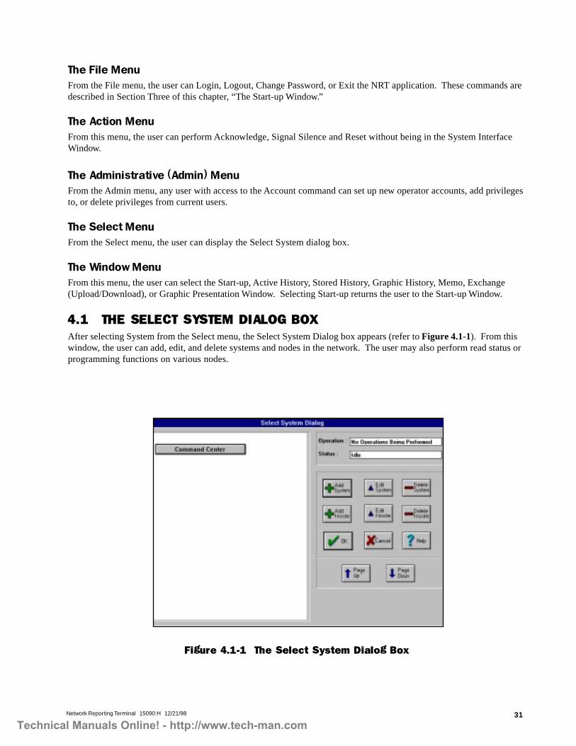
4.1 THE SELECT SYSTEM DIALOG BOXAfter selecting System from the Select menu, the Select System Dialog box appears (refer to Figure 4.1-1). From thiswindow, the user can add, edit, and delete systems and nodes in the network. The user may also perform read status orprogramming functions on various nodes.
Figure 4.1-1 The Select System Dialog Box
Technical Manuals Online! - http://www.tech-man.com

Network Reporting Terminal 15090:H 12/21/9832
System and Node ButtonsThe System and Node buttons let the user add, edit, or delete a User-Defined System. The user may also edit systems,delete systems, add nodes to systems, delete nodes from systems, and edit nodes in systems.
The Add System button from the Select System Dialog lets the user add a User-Defined System to the network. Afterthe user presses this button, the Program Custom Label dialog box displays and prompts for the name of the newcustom label (refer to Figure 4.1-2). After entering the name of the new label (system), the program displays the newsystem under the Command Center. Also note that in the Select System Dialog box, Dormitory is added (refer toFigure 4.1-3).
Figure 4.1-2 Program Custom Label
Figure 4.1-3 Adding a User-Defined System
NOTECurrently, only one User-Defined System may be added to the network. An error message appears whenthe user attempts to add more.
Technical Manuals Online! - http://www.tech-man.com

Network Reporting Terminal 15090:H 12/21/98 33
Figure 4.1-4 Node Type Selection Dialog Box
Edit System allows the user to change the name of the User-Defined System.
Delete System allows the user to delete a User-Defined System from the NRT. Press the Delete System button. Selectthe User-Defined System; then select Delete System. A warning box will appear. Select OK to delete or select Cancelto abort.
Add Node lets the user add a node to a system. From the Select System dialog box, select the system where the node isto be added. Press the Add Node button. A list of all available nodes will appear. The list displays Node 1 (N1)through Node 255 (N255). Use the PageUp and PageDown buttons to scroll through the list. Press the node to beadded. The Node Type Selection dialog box will appear (refer to Figure 4.1-4). The user can program the node to beone of five node types: AM2020, AFP1010, AFP-300/AFP-400, AFP200, INA, and Remote NRT. After selecting theapplicable node type, press OK.
NOTES1. Nodes may be added to a User-Defined System if the node is already programmed into the Command Center.2. A local NRT node will be present in the Command Center. To bring the NRT on line, double-click on the local
NRT node and change the node address to a value between 1 and 249. A Local NRT node cannot be pro-grammed using the Select System dialog box.
3. If a node type is programmed incorrectly, the NRT will automatically switch the node type to the correct type(i.e., an AM2020 programmed as an AFP1010 will be switched to an AM2020).
4. If the software is upgraded from a version prior to M2.8, and the local NRT was programmed into the addressrange 250-255, upon powerup the local NRT node address will reset to zero.
The Command Center must contain all nodes present on the network. The user must program all nodes into theCommand Center before programming the User-Defined System.
Edit Node allows the user to change the type of a particular node on the network.
GENERAL PROGRAMMING NO TES1. Programming / After Status actions can only be completed once every 5 seconds. If they are attempted faster than
that, a dialog box with the following information will be displayed: "Command could not be executed. Pleasetry again."
2. If for some reason a message can not be transmitted over the network, a dialog box with the following informa-tion will be displayed: "Command could not be executed. Please try again."
3. After a group disable command has been executed from the NRT, all further programming actions will beinhibited until the command has been completed on the FACP. If programming actions are attempted during thattime period, the NRT will display the following dialog box: "All programming functions are inhibited whilegroup zone disable / enable is in progress."
Technical Manuals Online! - http://www.tech-man.com

Network Reporting Terminal 15090:H 12/21/9834
To view nodes currently programmed into the system, double-click on the System button in the Select System Dialogbox to display a list of the nodes (refer to Figure 4.1-5). Double-clicking the System button shows a list of thesystems.
The Delete Node button deletes a node from a system. To do this, select the node to be removed. Press the DeleteNode button from the Select System Dialog box. A warning box will appear stating that the node will be removed fromthe system.
NOTES• The user cannot remove a node from the Command Center without removing it from all other User-Defined
Systems. If this is attempted, an error message will appear.
• The user cannot change the name of the Command Center.
• The user cannot remove the Local NRT node.
The Cancel ButtonThe Cancel Button places the user into the System Interface Window.
The OK ButtonWith a node selected, the OK button places the user in a Node dialog box from which Read Status/Programming can beperformed.
The AM2020 and AFP1010 Dialog BoxesFrom the AM2020 and AFP1010 dialog boxes, the user can programsensors, annunciators, modules, fire alarm control panels, zones, andperipherals (refer to Figure 4.2-1). For further information about program-ming parameters refer to Chapter Three of the AM2020/AFP1010 Manual(Document 15088).
4.2 NODE DIALOG BOXESFrom the Node dialog boxes, the user can program sensors, annunciators,modules, fire alarm control panels, zones, and peripherals for the variousnodes.
NOTEINA, Remote NRT, AFP-300/AFP-400 and AFP-200 programmingis not available in this software release.
Figure 4.1-5 Programmed Nodes in a System
Figure 4.2-1 AFP1010Dialog Box
Technical Manuals Online! - http://www.tech-man.com

Network Reporting Terminal 15090:H 12/21/98 35
Sensor ButtonTo program a detector from the NRT, press the Sensor button. Enter the address of the detector to be programmed.Press OK. The Detector dialog box will appear (refer to Figure 4.2-2). The title of the dialog box contains the device,network address and whether the point being displayed is installed.
Figure 4.2-3 Dialog Box Buttons
Undo - is not implemented in thisversion.
Filter - is not implementedin this release.
Back - returns the user tothe System InterfaceWindow.
Prior - moves the user tothe previous device(example: L1D1 is dis-played when programmingL1D2).
Remove - removes currentdevice from programming.
Help - opens the help file.
Next - moves the user to the nextdevice (example: L1D3 is dis-played when programming L1D2).
Displays keyboard for enteringinformation.
Close - returns the user to theNode dialog box.
Program - stores entered data into the NOTI�FIRE�NETNOTI�FIRE�NETNOTI�FIRE�NETNOTI�FIRE�NETNOTI�FIRE�NET.
Figure 4.2-2 Detector Dialog Box
Enter the detector label, type, annunciator mapping (if any), control-by-event (use ( ) if none), sensitivity settings,tracking, verification and day/night sensitivity information. When all information is entered, press the Program button(refer to Figure 4.2-3). Press the Close button to return to the Node dialog box.
NOTEThe Disable button does not appear until the point is programmed.
Using Dialog Box Buttons
Technical Manuals Online! - http://www.tech-man.com

Network Reporting Terminal 15090:H 12/21/9836
Annunciator ButtonTo program an annunciator panel from the NRT, press the annunciator button. Enter the address of the annunciatorpanel (for example, A1) and press OK. The Annunciator Panel dialog box appears (refer to Figure 4.2-4), where theuser can enter a custom label for the annunciator. After entering the label, press Program. Press Close to return to theNode dialog box.
Figure 4.2-5 Annunciator Point Dialog Box
Figure 4.2-4 Annunciator Panel Dialog Box
To program an annunciator point from the NRT, press the Annunciator button. Enter the address of the annunciatorpoint (for example, A1P1). Press OK. The Annunciator Point dialog box will appear (refer to Figure 4.2-5). Select thetype of point by selecting one of the choices under the Type drop-down menu and then press Program. To return to theNode dialog box, press Close. For more information on annunciator type I.D.s, refer to Chapter Three of the AM2020/AFP1010 manual, Document 15088.
Technical Manuals Online! - http://www.tech-man.com

Network Reporting Terminal 15090:H 12/21/98 37
Module ButtonThe module button allows the user to program a monitor or control module from the NRT. To do this, press the Modulebutton from the Node dialog box. Enter the address of the module to be programmed. Press OK. Depending on whatinformation was entered in the type field, either the monitor module dialog box (refer to Figure 4.2-6) or the controlmodule dialog box (refer to Figure 4.2-7) will appear. As with the detector and annunciator dialog boxes, the addressand whether the device is installed is displayed in the title bar. Enter the custom label, type, annunciator mapping (ifany) and control-by-event (use ( ) if none.) Note that after selecting the type of module, a dialog box will appearasking to begin installation. Press OK. Other options regarding the type of module being installed will appear. Whenfinished entering all applicable information, press Program. Then press Close to return to the Node dialog box.
The Disable button shows the state that the module will be put in when the button is pressed. If the Disable buttonshown in Figure 4.2-7 is pressed, the module will be disabled. After completing the action, the button will change toEnable. Note: Pressing the Disable/Enable button or the Activate/Deactivate button completes the action. TheProgram button should not be pressed in conjunction with these buttons.
NOTEThe Disable button does not appear until the point is programmed. For control modules the Activatebutton does not appear until the point is programmed.
Figure 4.2-7 Control Module Dialog Box
Figure 4.2-6 Monitor Module Dialog Box
Technical Manuals Online! - http://www.tech-man.com

Network Reporting Terminal 15090:H 12/21/9838
Figure 4.2-8 FACP Dialog Box
Figure 4.2-9 SLC Loop Dialog Box
FACP ButtonFACP allows the user to program FACP-wide Alarm Verification Time (seconds), Signal Silence Inhibit Time (seconds),Signal Cut-Out Time (seconds), AVPS installed, Zone Boundary, miscellaneous FACP information, and NFPA Listingsfrom the NRT. From the FACP dialog box, the user can also program LIB SLC loop information and battery specifica-tions (refer to Figures 4.2-8, 4.2-9, and 4.2-10).
SLC opens a dialog box where the user may enter LIB board and wiring style information. Also, Local Mode maxi-mum device information can be entered here.
Battery opens a dialog box where the user may enter information about the battery.
CAUTIONWhen a LIB is removed during programming, all points stored on that affected LIB will also be removed. Program-ming information for installed points can be stored in a VeriFire™ database prior to removal of a LIB. Use of the
VeriFire™ application for the reprogramming of previously removed points is highly recommended.
Technical Manuals Online! - http://www.tech-man.com

Network Reporting Terminal 15090:H 12/21/98 39
Zone ButtonThe Zone button allows the user to program zones from the NRT. From the Node dialog box, press the Zone button.Enter the number of the zone to be programmed. Press OK. The Zone dialog box will appear (refer to Figure 4.2-11).The user must enter a label, type of zone, annunciator mapping (if any), control-by-event, and cooperative control-by-event (use OR( ) if none). After entering applicable information, press Program. Press Close to return to the Nodedialog box. The cooperative control-by-event (CCBE) dialog box is only accessible for reverse zones.
NOTEThe Disable and Group Zone Disable buttons do not appear until after the zone is programmed.
Figure 4.2-10 Battery Dialog Box
Figure 4.2-11 Zone Dialog Box
Technical Manuals Online! - http://www.tech-man.com

Network Reporting Terminal 15090:H 12/21/9840
Local NRT Node Dialog BoxLocal NRT parameters can be programmed by selecting the local NRT node from the Select System dialog box andpressing OK or double-clicking the node. The Local NRT Program dialog box appears (refer to Figure 4.2-13). Fromthis dialog box, the user can program the address, thresholds, ports supervision, and settings for the local NRT node.When finished entering all the information press Program. Press Back to go to the System Interface Window. Afterprogramming the Local NRT, press Close.
NOTEReceive Mode is not implemented in this release. When an NRT is used with the NOTI�FIRE�NETsystem, all network nodes must be configured for block acknowledge. Nodes configured for receiv-
ing unit mode will not function properly and troubles will not be acknowledged.
The local NRT date and time can also be modified from this dialog box. The frequencies for alarm and trouble soundsmay be modified solely for the NRT, with no effect to any fire panel. Setting different frequencies for alarms andtroubles makes them distinguishable from each other. At least a 200 Hz difference is required in the lower Hz range(less than 2000) so that the alarm and trouble sounds can be distinguished from each other. Fan supervision is notrequired on the NRT and should be disabled. The default (checked) enables fan failure troubles on the NRT.Uncheck the Fan Supervision check box in the Local NRT Node Dialog Box.
Peripherals ButtonThe Peripherals dialog box allows the user to enter programming information from the NRT for terminal and printerinterfaces attached to the node. From the Node dialog box, press the Peripherals button. The Peripherals dialog boxwill appear (refer to Figure 4.2-12). After entering all applicable information, press Program. Press Close to return tothe Node dialog box.
Figure 4.2-12 Peripherals Dialog Box
To return to the Select System dialog box, press Cancel in the Node dialog box.
Technical Manuals Online! - http://www.tech-man.com

Network Reporting Terminal 15090:H 12/21/98 41
Figure 4.2-13 Local NRT Program Dialog Box
* To take the Local NRT off-line (stop communicating on the network), set the local NRT address to 0.
CAUTION!!
Taking the Local NRT off-line causes the NRT to stop communicating with the NOTI�FIRE�NET NOTI�FIRE�NET NOTI�FIRE�NET NOTI�FIRE�NET NOTI�FIRE�NET net-work, which leaves the building unprotected and the NRT not performing Life Safety functions.
** The last AM2020/AFP1010, AFP-300/AFP-400, INA, or NRT on NOTI�FIRE�NETNOTI�FIRE�NETNOTI�FIRE�NETNOTI�FIRE�NETNOTI�FIRE�NET to have its time/datemanually changed becomes the network master for clock synchronization. To avoid confusion, it is impor-tant to decide which node will be the master clock keeper and only change the time and date on that node.The clocks are synchronized every hour. The network time and date appears in the upper right-hand cornerof all NRT windows. The node address of the master time keeper is displayed in the Node field of the Timerbox. If a node address of 0 is displayed in the Node field, the NRT is not the master time keeper, and did notreceive a time update from the network. If this condition persists for more than 3 hours, enter the time/dateon a node to re-establish a master time keeper.
Address: NOTI�FIRE�NETNOTI�FIRE�NETNOTI�FIRE�NETNOTI�FIRE�NETNOTI�FIRE�NET address.*
Threshold: MIB communication thresholds for Ports A and B. MIB-WF only requires thresholdsettings for Port A.
Ports Supervision: NOTI�FIRE�NETNOTI�FIRE�NETNOTI�FIRE�NETNOTI�FIRE�NETNOTI�FIRE�NET wiring configuration.
Settings: Data Refresh allows update of graphic screens after a node is added to the network.Uncheck UPS Supervision; it is not required.
Timer: Change the time and date of a specific node.**
Sound (Hz): Define separate alert tones for alarm and trouble conditions.
Password: Allows the user to disable or enable the automatic password time-out feature and set thetime-out value if the feature is enabled.
Technical Manuals Online! - http://www.tech-man.com
Network Reporting Terminal 15090:H 12/21/9842
SECTION FIVE THE ACTIVE/STORED HISTORY
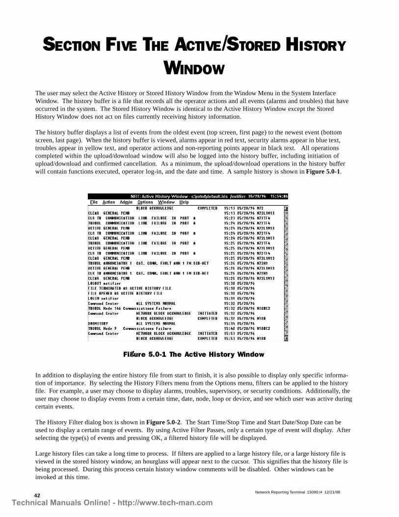
WINDOWThe user may select the Active History or Stored History Window from the Window Menu in the System InterfaceWindow. The history buffer is a file that records all the operator actions and all events (alarms and troubles) that haveoccurred in the system. The Stored History Window is identical to the Active History Window except the StoredHistory Window does not act on files currently receiving history information.
The history buffer displays a list of events from the oldest event (top screen, first page) to the newest event (bottomscreen, last page). When the history buffer is viewed, alarms appear in red text, security alarms appear in blue text,troubles appear in yellow text, and operator actions and non-reporting points appear in black text. All operationscompleted within the upload/download window will also be logged into the history buffer, including initiation ofupload/download and confirmed cancellation. As a minimum, the upload/download operations in the history bufferwill contain functions executed, operator log-in, and the date and time. A sample history is shown in Figure 5.0-1.
In addition to displaying the entire history file from start to finish, it is also possible to display only specific informa-tion of importance. By selecting the History Filters menu from the Options menu, filters can be applied to the historyfile. For example, a user may choose to display alarms, troubles, supervisory, or security conditions. Additionally, theuser may choose to display events from a certain time, date, node, loop or device, and see which user was active duringcertain events.
The History Filter dialog box is shown in Figure 5.0-2. The Start Time/Stop Time and Start Date/Stop Date can beused to display a certain range of events. By using Active Filter Passes, only a certain type of event will display. Afterselecting the type(s) of events and pressing OK, a filtered history file will be displayed.
Large history files can take a long time to process. If filters are applied to a large history file, or a large history file isviewed in the stored history window, an hourglass will appear next to the cucsor. This signifies that the history file isbeing processed. During this process certain history window comments will be disabled. Other windows can beinvoked at this time.
Figure 5.0-1 The Active History Window
Technical Manuals Online! - http://www.tech-man.com

Network Reporting Terminal 15090:H 12/21/98 43
Figure 5.0-2 The History Filter Dialog Box
5.1 CHANGING THE ACTIVE HISTORY BUFFERFrom the Active History Window, the user can start a new history buffer or open an existing history buffer as thecurrently active history buffer. From the File Menu, select New to open a new file as the currently active history buffer.
After selecting New from the File menu, the File Save As dialog box appears. Enter the name of the new history bufferfile with file extension “.HIS.” The user can also change the file directory to save the file in a different location. Whenfinished, press OK to accept; or Cancel to abort.
To open an existing file as the currently active history buffer, select Open… from the File menu. The File Open dialogbox will appear. After selecting an existing file, press OK to accept this information or Cancel to abort. Note: Historyfiles may be backed up using the magnetic tape backup system (refer to Section Three in Chapter One of this manual).
5.2 CHANGING THE STORED HISTORY FILETo view a different stored history file, select Open… from the File menu in the Stored History Window. The File Opendialog box will appear. Select a different file to view and press either OK to accept or Cancel to abort.
5.3 PRINTING THE ACTIVE/STORED HISTORY WINDOWThe printing option lets the user print an Active History Window or a Stored History Window (refer to Figure 5.3-1).The window print contains all events that take place up to the printing confirmation. When printing, note the follow-ing:
• The user may only print one window at a time.• The window print exceeds the usual width of incoming events. To avoid printer line wrap, set the printer pitch to
a minimum of 12 characters per inch (CPI) (12 characters per 25.4 mm).• The window print format differs from the active display window.
To print a window, do the following:
1. Select and display the desired window.2. Select the Print Command; confirm the active window in the Print dialog box, and press OK.
The application prints the active window as the network processes other activities.
NOTEThe Print menu item is disabled while printing.
Technical Manuals Online! - http://www.tech-man.com

Network Reporting Terminal 15090:H 12/21/9844
Command Center NETWORK SYSTEM RESET REQUESTED 15:29 03/02/95SYSTEM RESET ACTIVATED 15:29 03/02/95
Custom ALL SYSTEMS NORMAL 15:29 03/02/95
***************************START OF ACTIVE/STORED HISTORY PRINTOUT **********************c:\nfn\ui\debug\sample.his
1 FILE CREATED 15:18 03/02/952 FILE OPENED AS ACTIVE HISTORY FILE 15:18 03/02/953 FILE TERMINATED AS ACTIVE HISTORY FILE 15:18 03/02/954 FILE OPENED AS ACTIVE HISTORY FILE 15:18 03/02/955 Command Center NETWORK SYSTEM RESET REQUESTED 15:18 03/02/956 SYSTEM RESET ACTIVATED 15:18 03/02/95 Node 17 Custom ALL SYSTEMS NORMAL 15:19 03/02/958 Command Center NETWORK SYSTEM RESET REQUESTED 15:19 03/02/959 SYSTEM RESET ACTIVATED 15:19 03/02/95 Node 110 Custom ALL SYSTEMS NORMAL 15:19 03/02/9511 FILE TERMINATED AS ACTIVE HISTORY FILE 15:21 03/02/9512 FILE OPENED AS ACTIVE HISTORY FILE 15:27 03/02/9513 TROUBL NRT Fan Failure 15:27 03/02/95 N3C614 DATA DUMP - Initiated for node 1 15:27 03/02/9515 Command Center NETWORK BLOCK ACKNOWLEDGE INITIATED 15:27 03/02/9516 BLOCK ACKNOWLEDGE COMPLETED 15:27 03/02/95 Node 317 TROUBL Node 5 Communications Failure 15:27 03/02/95 N3C218 TROUBL Node 6 Communications Failure 15:27 03/02/95 N3C219 TROUBL Node 7 Communications Failure 15:27 03/02/95 N3C220 TROUBL Node 10 Communications Failure 15:27 03/02/95 N3C221 Custom ALL SYSTEMS NORMAL 15:28 03/02/9522 Command Center NETWORK BLOCK ACKNOWLEDGE INITIATED 15:28 03/02/9523 BLOCK ACKNOWLEDGE COMPLETED 15:28 03/02/95 Node 324 DATA DUMP - Successfully Completed for node 1 15:28 03/02/9525 Command Center NETWORK SYSTEM RESET REQUESTED 15:29 03/02/9526 SYSTEM RESET ACTIVATED 15:29 03/02/95 Node 127 Custom ALL SYSTEMS NORMAL 15:29 03/02/95*****************************END OF ACTIVE/STORED HISTORY PRINTOUT************************Command Center NETWORK SYSTEM RESET REQUESTED 15:30 03/02/95
SYSTEM RESET ACTIVATED 15:30 03/02/95 Node 1Custom ALL SYSTEMS NORMAL 15:31 03/02/95
Line Num-bers
Start Banner Path and Name of the Window Print
End Banner Figure 5.3-1 Sample Window Print
Note the following items on the sample print in Figure 5.3-1:
• Start banner – contains the events at the start of printing.• Path and name – lists the directory and user-defined file name of the window print.• Line numbers – lists the events as they occur during printing.• End banner – lists new events that occurred during printing.
IMPORTANT!!1. It is possible to print the history file with history filters applied. The printout must be completed before the
history filters are removed when printing specific events.
2. The print setup dialog should only be used if problems are experienced while trying to print large files suchas the history files. The delay setting (lines per second) can be increased or decreased to help speed upprinting or to keep the system from freezing up during large print jobs. The minimum delay setting allowedis 3 seconds and the maximum is 300 seconds. The minimum line setting is 1 line and the maximum is 40lines. In the print setup dialog box, the best setting for the PRN-4 printer is the default 2 lines per 3 seconds.If you experience problems during printing, contact your Notifier representative.
Technical Manuals Online! - http://www.tech-man.com

Network Reporting Terminal 15090:H 12/21/98 45
5.4 THE GRAPHIC HISTORY WINDOWAs an alternative to displaying a list of events in text format from the history file, the user can display this informationin a graphic format. To do so, select Graphic History from the Window Menu (refer to Figure 5.4-1).
From the Graphic History Window, the user can display the active history buffer or a selected history buffer file (.HIS) asa graphic. To display a history file, choose Open from the File menu. The File open box will appear. After selecting a file,press OK to accept; or press Cancel to abort. After pressing OK, the Graphic History Selection dialog box appears. Fromthe Graphic History Selection dialog box, the user can choose to display only a certain year, month, or day and a numberof different graphs, such as bar graph, point graph, line graph, or spline graph. Only alarms, only troubles, or both may bedisplayed. After selecting this information, press OK. The information will then be displayed graphically on the screen.To change the graph format, select Show Graph… within the Options menu and the Graphic History Selection dialog boxwill display (refer to Figure 5.4- 2).
Figure 5.4-1 The Graphic History Window
Figure 5.4-2 The Graphic History Selection Dialog Box
Technical Manuals Online! - http://www.tech-man.com

Network Reporting Terminal 15090:H 12/21/9846
SECTION SIX THE MEMO WINDOWThe Memo window is a text editor which allows the user to create or edit files used as operator logs. These files have a.TXT file extension and can be up to 64K file size.
The File MenuThe file menu allows the user to create new, open, save, or delete text files.
The Edit MenuThe Edit menu allows the user to edit text through the Undo, Cut, Copy, Paste, Delete, Clear, Find … , Replace … , and Nextcommands.
The Action MenuFrom this menu, the user can perform Acknowledge, Signal Silence, and Reset without being in the System InterfaceWindow.
The Window MenuFrom the Window Menu, the user can access any other window in the NRT program.
Technical Manuals Online! - http://www.tech-man.com

Network Reporting Terminal 15090:H 12/21/98 47
SECTION SEVEN
THE UPLOAD/DOWNLOAD WINDOWThe Upload/Download Window is accessed from Exchange in the Window Menu of the System Interface window. TheExchange feature allows the user to transmit an entire database from a fire alarm panel to the NRT and download anentire database from the NRT to the panel.
NOTEAll operations completed in the Upload/Download Window will be logged into the Active History Win-dow.
The Upload/Download graphic window contains the Node window, Status window, a Logging window (see Figure 7.0-1) and a Percentage Complete window . The Node window displays the address of the current node being uploaded/downloaded. The Status Window displays system managers for the current node being uploaded or downloaded. ThePercentage Complete window displays how the upload/download has progressed. The Logging Window displaysactions, errors, and warnings. Warnings are displayed in yellow and include CBE or CCBE equations incorrectlystored in the database. Errors are displayed in red. Errors are items that prohibit the upload/download feature tofunction such as nodes going off-line, abort function executed, or nodes not responding with the data requested by theNRT.
Figure 7.0-1 The Upload/Download Graphic Window
The Upload/Download window contains buttons used to initiate the upload/download process (see Figure 7.0-1) TheUpload button initiates an upload, the Download button initiates the download, the Abort button will cancel thecurrent process, and the Schedule button allows the user to schedule monthly uploads (see Section 7.2). Upload,download, abort, and schedule may also be selected from the Exchange menu in the Upload/Download window (seeFigure 7.0-2).
Figure 7.0-2 The Exchange Menu
Technical Manuals Online! - http://www.tech-man.com

Network Reporting Terminal 15090:H 12/21/9848
Figure 7.1-1 Upload Dialog Box
NOTEDuring the NRT read status, the fire panel does not send data for any points for which there is no LIBSLC loop installed or programmed into the panel. Before sending a message to the LIB SLC loop fora point read, the fire panel's CPU checks to make sure the LIB is installed. Points that have beenprogrammed into the panel but have no corresponding LIB SLC loop, will cause the upload to abort.
7.2 Scheduling UploadsThe NRT has a scheduling feature which allows the user to upload all or some panels at a specified time and date.Panels are uploaded sequentially, starting with the lowest node address. Scheduled uploads are differentiated fromuser-initiated uploads in the active history window.
To schedule an upload, press on the Schedule button in the Upload/Download window or select Schedule from theExchange menu. The Schedule Upload dialog box will appear (see Figure 7.2-1).
To begin an upload, press the Upload button. A current database must be opened using the Open button, or a newdatabase created using the New button and a node selected. If a current database is opened and information for theselected node is already stored in the database, all current node information in the database will be deleted before theupload proceeds. Press the Start button to initiate the upload process. If the node selected for upload is not anAM2020 or AFP1010 panel, a dialog box will appear indicating that upload for the selected node cannot be imple-mented (see Figure 7.1-1). The Upload/Download feature is not currently implemented for INAs, AFP-200s, or otherNRTs.
7.1 UploadOnly one node may be uploaded at a time and no catastrophic failures such as LIB Communications Trouble can existon the node being uploaded. Catastrophic failures cause the fire panel to reboot every 15 minutes, causing the node togo off line and thus aborting the upload process. The Read Status and Programming functions will be disabled for anynode currently being uploaded, but can be performed on any other node. All fire protection is enabled during anupload.
Technical Manuals Online! - http://www.tech-man.com

Network Reporting Terminal 15090:H 12/21/98 49
Figure 7.2-1 The Schedule Upload Dialog Box
Uploads can be scheduled at a specific time only once or once a month. The Time field in the Schedule Upload DialogBox, requires 24 hour (military) time. To alleviate the problem of months with 28, 30, or 31 days, the user may onlychoose days between the 1st and 28th of the month. The Schedule Upload dialog box contains a list of all theAM2020 and AFP1010 panels that are programmed into the NRT. All nodes or a user-defined group of nodes may bechosen for the scheduled upload. Nodes may be added to or deleted from the available node list by pressing the open,delete, or next buttons.
7.3 DownloadOnly one node may be downloaded at a time and no catastrophic failures such as LIB Communications Trouble canexist on the node receiving data. Catastrophic failures cause the fire panel to reboot every 15 minutes, causing thenode to go off line and thus aborting the download process. The Read Status and Programming functions will bedisabled for any node currently being downloaded, but can be performed on any other node. Warning: Fire protec-tion and life safety functions are limited during a download.
Downloading is initiated by pressing the Download button. A read status determines which LIB SLC loops areprogrammed into the panel and only points with a corresponding loop can be downloaded to the panel.
During the download process, points are either programmed or reprogrammed. False alarms can occur due to incorrector partial downloads. The user must thoroughly check the programming information prior to initiating a download.
7.4 AbortPressing the abort button will abort the current upload or download process. Aborting the process leaves a partialdatabase in the panel (during download). CAUTION: If the download is aborted, the fire panel may be in a corruptstate and the life safety protection provided by the panel may not operate correctly. If a download is aborted, thefire panel will have to be reprogrammed. A confirmation dialog box will be displayed after pressing the Abort button,asking the user if they want to abort the upload/download operation. If the user chooses OK, the upload/downloadprocess will stop. If the user chooses Cancel, the process will continue. Confirmed abort actions will appear in thehistory buffer and will be displayed in the Logging window of the Upload/Download window.
Technical Manuals Online! - http://www.tech-man.com

Network Reporting Terminal 15090:H 12/21/9850
SECTION EIGHT
THE GRAPHIC PRESENTATION WINDOWThe Graphic Presentation Window, accessible from any window, allows the user to display floor plans in which deviceinformation is embedded. When a device goes into alarm or trouble, the Graphic Presentation Window displays theevent by flashing and changing the color of the device that goes into alarm/trouble. The user can also obtain deviceinformation, view bitmapped (.BMP) graphics, and perform Read Status of each device.
8.1 APPLYING ATTRIBUTES TO A CAD FILETo program devices for use with NRT software, use CAD software that supports attributes, creates blocks, and exportsCAD files in the .DXF file format. The programmer must have floor plans of the site (in a CAD program) and locationsof devices.
NOTEAll CAD drawings must be saved using Autocad version 12 or older, or Autocad Lite 2.1 or older. TheNRT does not recognize any newer file formats.
Enter every device in a CAD drawing as a block insert using the CAD program's "Make Block" or similar function.During the block insert function, the program prompts for the following three attributes:
• Information (optional)• Picture (optional)• Address
The Information attribute contains the path to the name of a text (.TXT) file unique to each device. TXT files can becreated from the Memo Window (see Section Six of this chapter). The .TXT file can contain any character informationthat the end-user wants to access from the screen display window.
The Picture attribute contains the path to the name of a bitmap (.BMP) file unique to each device. This .BMP file cancontain any graphic image that the end-user wants to access from the screen display window.
The Address is the address of the device on the network. Make sure to enter the node number, loop number, and devicenumber (for example, N3L2D24).
After entering all devices into the CAD drawing as inserted blocks, export the drawing from the CAD program as a.DXF file. Create a subdirectory on the C: drive of the NRT where all .DXF files can be placed. Place this .DXF fileinto the subdirectory.
NOTEThe NRT graphics software will not function properly if more than one block is inserted for any singledevice.
8.1.1 The AFP-300/AFP-400The AFP-400 is a two loop panel that contains 4 bell circuits and 64 panel circuits. The AFP-300 is a single loop panelthat contains 4 bell circuits and 64 panel circuits. To add these point types to the NRT Graphic Presentation Window,they must be addressable in the Graphics Window on the standard node, loop, device address format. For this purpose,Loop 3 is reserved for bell and panel circuits for AFP-300/AFP-400 panels. Reference the table on the following pageto add these devices to the Graphic Presentation Windows:
Technical Manuals Online! - http://www.tech-man.com

Network Reporting Terminal 15090:H 12/21/98 51
8.2 PROGRAMMING THE NRTThe .DXF file created from the CAD drawing will be divided into graphic screens that will be displayed in the NRTGraphic Presentation Window. The NRT saves each screen background as a bitmap (.BMP) file, and all devices anddevice information in a .DXF file. This allows the NRT to quickly display the screen backgrounds using the .BMP fileand to immediately display troubles and alarms because the .DXF files can be quickly scanned quickly with nobackground data.
Programming graphic screens into the NRT requires the following three steps:1. Create the background file and hide or remove all devices.2. Install the background file and create the bitmap file.3. Create the device file and remove the background.
The diagram in Figure 8.2-1 illustrates this process.
004-PFA/003-PFAsserddA
noitatneserPcihparGsserddAwodiW
004-PFA/003-PFAsserddA
noitatneserPcihparGsserddAwodiW
1tiucriClleB 1M3L 7-4tiucriClenaP 93M3L
2tiucriClleB 2M3L 8-4tiucriClenaP 04M3L
3tiucriClleB 3M3L 1-5tiucriClenaP 14M3L
4tiucriClleB 4M3L 2-5tiucriClenaP 24M3L
3-5tiucriClenaP 34M3L
1-1tiucriClenaP 9M3L 4-5tiucriClenaP 44M3L
2-1tiucriClenaP 01M3L 5-5tiucriClenaP 54M3L
3-1tiucriClenaP 11M3L 6-5tiucriClenaP 64M3L
4-1tiucriClenaP 21M3L 7-5tiucriClenaP 74M3L
5-1tiucriClenaP 31M3L 8-5tiucriClenaP 84M3L
6-1tiucriClenaP 41M3L 1-6tiucriClenaP 94M3L
7-1tiucriClenaP 51M3L 2-6tiucriClenaP 05M3L
8-1tiucriClenaP 61M3L 3-6tiucriClenaP 15M3L
1-2tiucriClenaP 71M3L 4-6tiucriClenaP 25M3L
2-2tiucriClenaP 81M3L 5-6tiucriClenaP 35M3L
3-2tiucriClenaP 91M3L 6-6tiucriClenaP 45M3L
4-2tiucriClenaP 02M3L 7-6tiucriClenaP 55M3L
5-2tiucriClenaP 12M3L 8-6tiucriClenaP 65M3L
6-2tiucriClenaP 22M3L 1-7tiucriClenaP 75M3L
7-2tiucriClenaP 32M3L 2-7tiucriClenaP 85M3L
8-2tiucriClenaP 42M3L 3-7tiucriClenaP 95M3L
1-3tiucriClenaP 52M3L 4-7tiucriClenaP 06M3L
2-3tiucriClenaP 62M3L 5-7tiucriClenaP 16M3L
3-3tiucriClenaP 72M3L 6-7tiucriClenaP 26M3L
4-3tiucriClenaP 82M3L 7-7tiucriClenaP 36M3L
5-3tiucriClenaP 92M3L 8-7tiucriClenaP 46M3L
6-3tiucriClenaP 03M3L 1-8tiucriClenaP 56M3L
7-3tiucriClenaP 13M3L 2-8tiucriClenaP 66M3L
8-3tiucriClenaP 23M3L 3-8tiucriClenaP 76M3L
1-4tiucriClenaP 33M3L 4-8tiucriClenaP 86M3L
2-4tiucriClenaP 43M3L 5-8tiucriClenaP 96M3L
3-4tiucriClenaP 53M3L 6-8tiucriClenaP 07M3L
4-4tiucriClenaP 63M3L 7-8tiucriClenaP 17M3L
5-4tiucriClenaP 73M3L 8-8tiucriClenaP 27M3L
6-4tiucriClenaP 83M3L lbt.004pfatrN
Table 8.1-1 AFP-300/AFP-400 Bell and Panel Circuits
Technical Manuals Online! - http://www.tech-man.com

Network Reporting Terminal 15090:H 12/21/9852
PARENT.DXF
WORK.DXF
CustomLabel
.BMP
WORK.DXF
[ ]
Step 1: Copy parent file (PARENT.DXF)with devices and background to work file(WORK.DXF) and hide or remove devicesfrom work file.
Step 2: Install WORK.DXF into thescreen tree, display, and press F2 tocreate bitmap file.
Step 3: Copy parent file with devices and back-ground to second work file (WORK.DXF) andremove background from work file.
Figure 8.2-1 Example Process for Programming Graphic Screens
Use the example in Figure 8.2-1 above as a guideline for completing the steps outlined below.
Step 1 - Creating the Background FileThe parent file (PARENT.DXF) is the CAD drawing which contains both the drawing background and the devicesentered as block inserts. In Step 1, copy PARENT.DXF to a working file. In the example above (Figure 8.2-1), thecopy is named WORK.DXF. Use a CAD program to hide or remove all devices from WORK.DXF. When finished,WORK.DXF should only display the background of the architectural drawing.
Step 2 - Installing the Background File and Creating the BitmapStep 2 installs the WORK.DXF background file and converts it into a bitmap (.BMP) file for use in the GraphicPresentation Window. Start the NRT software and go to Graphic Presentation under the Window menu. Go to theSelect menu and select Screen. The Select Screen dialog box will appear (refer to Figure 8.2-2 below).
Figure 8.2-2 The Select Screen Dialog Box
COPY
COPY
F2 KEY
Technical Manuals Online! - http://www.tech-man.com

Network Reporting Terminal 15090:H 12/21/98 53
Figure 8.2-4 Determining CAD Coordinates
Figure 8.2-3 The File Open Dialog Box
In the Select Screen Dialog box, press the Add Screen button to begin creating the floor plan screens. The File Opendialog box will appear. Enter the path and name of the background work file created in Step 1 (WORK.DXF). The filename should appear in the Filename: box (refer to Figure 8.2-3). Enter an eight-character custom label. The customlabel will later appear in the Select Screen dialogue box.
Enter the CAD coordinates. The Maximum Horz., Maximum Vert., Minimum Horz. and Minimum Vert. entries arecoordinates the programmer uses to indicate which part of the WORK.DXF will be displayed for this specific eight-character custom label. These coordinates are taken from the CAD drawing (units). To view portions of a drawing (forexample, a floor or specific room), take the coordinates from the CAD package and enter these coordinates into theFile Open Dialog box displayed in Figure 8.2-3. The Maximum Horz. and Maximum Vert. represent the upper rightcoordinates of the area the user wants to display. The Minimum Horz. and Minimum Vert. represent the lower leftcoordinates of the area (refer to Figure 8.2-4).
X
Area to bedisplayed
X
(0,0)
Maximum Horz.Maximum Vert.
(34,22)
Minimum Vert.Minimum Horz.
NOTEThe custom label and CAD coordinates must be entered for each screen added.
After entering Custom label and CAD coordinates, press OK. This brings you back to the Select Screen dialog box.The graphic screens display in a treelike fashion in the dialog box. The new screen's custom label should appear onthe tree. Highlight the new screen created from WORK.DXF and press OK. This brings the floor plan up on theGraphic Presentation Window. Press the F2 key on your keyboard to create the .BMP file with the same name as theeight-character custom label.
Repeat Step 2 for each screen to be added to the tree in the Select Screen dialog box (all .DXF screens to be viewedmust be added in this dialog box). To add a subscreen to the tree, select the screen under which the new screen will beinserted before pressing the Add Screen button. For example, if the office building has 22 floors, the tree view wouldcontain the "office" screen with floor plan screens of each floor under the main office screen. (Refer to Figure 8.2-5)
Technical Manuals Online! - http://www.tech-man.com

Network Reporting Terminal 15090:H 12/21/9854
Figure 8.2-5 Adding a Subscreen to the Select Screen Dialog Box
Step 3 - Creating the Device FileIn Step 3, copy the original parent file, PARENT.DXF, to a working file as done in Step 1. Use the same file name asused in Step 1, WORK.DXF. After copying the file, use the CAD program to remove all background entities fromWORK.DXF. When finished, WORK.DXF should only display the devices. The background is stored in CUSTOMLABEL.BMP created in Step 2 and should not be in the new working .DXF file. Make sure that the device file createdin this step is always named with the same name as it's corresponding background file created in Step 1.
After changing or inputting system screens, exit and restart the NRT application to ensure proper operation. From themain NRT window, select Graphic Presentation under the Window menu. Select Screen under the Select menu. Thiswill bring up the Select Screen dialog box with the new screens. Select a screen and press OK. This will bring up acombined screen of the floor plan background bitmap created in Step 2 and the device plan created in Step 3. Alldevices should now appear as a green triangle/square with the network address.
Select Screen Dialog Box ButtonsThe Edit button allows the user to edit the custom label of the screen and the coordinates of the current file.
To delete a screen, select the screen to delete in the Select Screen dialog box. Press the Delete button to delete thescreen.
The Cancel button closes the Select Screen dialog box and displays the Screen Display Window.
The Toggle button allows the user expand or collapse the view of the screen tree, showing only the main parent screenor the parent screen and all of its sub screens.
The Scroll Up, Scroll Left, Scroll Right, and Scroll Down buttons move the Select Screen dialog box to accessscreens not shown.
8.3 CUSTOMIZING THE GRAPHIC ICONSThe NRT has the ability to allow customized icons for a group of devices. A text file, property.dat, must reside in theNRT directory. The following iss an example of a property.dat file, which shows the exact layout necessary for thedevices to be associated with bitmap groups.
NOTEThe full path must be given for each bitmap state.
Technical Manuals Online! - http://www.tech-man.com

Network Reporting Terminal 15090:H 12/21/98 55
normal = c:\bitmaps\smoke2.bmp,alarm = c:\bitmaps\smoke3.bmp,aalarm = c:\bitmaps\smoke3a.bmp,trouble = c:\bitmaps\smoke4.bmp,atrouble = c:\bitmaps\smoke4a.bmp,security = c:\bitmaps\smoke5.bmp,asecurity = c:\bitmaps\smoke5a.bmp,
address = N1L1D1,address = N1L1D2,address = N1L1D3,address = N1L1D4;
normal = c:\bitmaps\smoke12.bmp,alarm = c:\bitmaps\smoke13.bmp,aalarm = c:\bitmaps\smoke13a.bmp,trouble = c:\bitmaps\smoke14.bmp,atrouble = c:\bitmaps\smoke14a.bmp,security = c:\bitmaps\smoke15.bmp,asecurity = c:\bitmaps\smoke15a.bmp,
address = N1L1D11,address = N1L1D12,address = N1L1D13,address = N1L1D14;
normal = c:\bitmaps\pull1.bmp,alarm = c:\bitmaps\pull2.bmp,aalarm = c:\bitmaps\pull2a.bmp,trouble = c:\bitmaps\pull3.bmp,atrouble = c:\bitmaps\pull3a.bmp,security = c:\bitmaps\pull4.bmp,asecurity = c:\bitmaps\pull4a.bmp,
address = N1L1M1,address = N1L1M2,address = N1L1M3,address = N1L1M4;
In the above example, a group of seven bitmap states are listed with the literal path to the bitmap file first, followed bya blank line. All the devices which use the group bitmaps are listed. The last device listed for a bitmap group MUSThave a semi-colon (;) at the end of the line. This seperates one bitmap grouping from another. All other lines shouldend in a comma.
As in the above example, another group can be added (bitmaps and then devices) after the semi-colon which ends aprevious group. The end of the file is marked by the last semi-colon of the last device entry; no other special charac-ters are needed.
Technical Manuals Online! - http://www.tech-man.com

Network Reporting Terminal 15090:H 12/21/9856
8.4 SETTING UP THE ZOOM FEATUREThe NRT will allow a zoom feature if so defined. This feature is designed to give a more detailed view of a device andthe surrounding area. The following steps must be taken to correctly set up the zoom feature.
1. Define a parent screen that contains a device or set of devices.2. Add a sub-screen to the parent screen. The same device or devices must be defined on the sub-screen.
Parent Screen
Sub-Screen 1
Sub-Screen 2
Sub-Screen 3
When a signal is received, the device on the parent screen will be displayed. The zoom-in feature then will find thesame device on the sub-screen. If more sub-screens are defined with the same device(s) on all, subsequent zoom-incommands will vector to the next level.
8.5 AUTOMATIC SCREEN VECTORINGThe NRT graphics system automatically changes the displayed screen to show the highest priority event. Thisfunction is called "Automatic Screen Vectoring" or "Screen Vectoring."
Screen vectoring uses the same event priority algorithms as the System Interface Window. The user can still manuallychange screens using the Select Screen dialog box.
NOTEAutomatic screen vectoring is only enabled if the NRT is in the Graphic Presentation window.
Technical Manuals Online! - http://www.tech-man.com
Network Reporting Terminal 15090:H 12/21/98 57
NETWORK REPORTING TERMINAL
(NRT)
CHAPTER THREE
OPERATION
Technical Manuals Online! - http://www.tech-man.com

Network Reporting Terminal 15090:H 12/21/9858
SECTION ONE NORMAL OPERATIONDuring normal operation, when no fire alarms or troubles exist, the command center and user-defined system willappear as shown below with an "All Systems Normal" message in each alarm and trouble window.
The user can perform functions associated with the following buttons without having to enter a password:
ACK The Ack (acknowledge) button acknowledges events currently in the system. Alarms areacknowledged individually, and troubles are acknowledged as a group (block acknowledge).Receiving unit mode is not supported on the NRT and all nodes on the network should beconfigured for block acknowledge.
SIG SIL The Sig Sil (signal silence) button silences all control modules in the system that are pro-grammed as silenceable. The System Interface Window will reflect that a signal silence isrequested.
RESET The reset button resets all fire panels for the particular system in which it was requested.
Technical Manuals Online! - http://www.tech-man.com
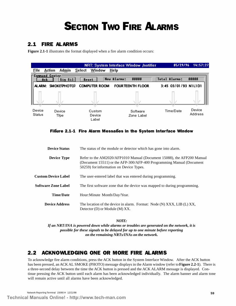
Network Reporting Terminal 15090:H 12/21/98 59
SECTION TWO FIRE ALARMS
2.1 FIRE ALARMSFigure 2.1-1 illustrates the format displayed when a fire alarm condition occurs:
CustomDeviceLabel
Figure 2.1-1 Fire Alarm Messages in the System Interface Window
Device Status The status of the module or detector which has gone into alarm.
Device Type Refer to the AM2020/AFP1010 Manual (Document 15088), the AFP200 Manual(Document 15511) or the AFP-300/AFP-400 Programming Manual (Document50259) for information on Device Types.
Custom Device Label The user-entered label that was entered during programming.
Software Zone Label The first software zone that the device was mapped to during programming.
Time/Date Hour:Minute Month/Day/Year.
Device Address The location of the device in alarm. Format: Node (N) XXX, LIB (L) XX,Detector (D) or Module (M) XX.
2.2 ACKNOWLEDGING ONE OR MORE FIRE ALARMSTo acknowledge fire alarm conditions, press the ACK button in the System Interface Window. After the ACK buttonhas been pressed, an ACK AL SMOKE (PHOTO) message displays in the Alarm window (refer to Figure 2.2-1). There isa three-second delay between the time the ACK button is pressed and the ACK ALARM message is displayed. Con-tinue pressing the ACK button until each alarm has been acknowledged individually. The alarm banner and alarm tonewill remain active until all alarms have been acknowledged.
NOTE:If an NRT/INA is powered down while alarms or troubles are generated on the network, it is
possible for these signals to be delayed for up to one minute before reportingon the remaining NRTs/INAs on the network.
DeviceType
Time/Date DeviceAddress
SoftwareZone Label
DeviceStatus
ALARM: SMOKE(PHOTO) COMPUTER ROOM FOURTEENTH FLOORALARM: SMOKE(PHOTO) COMPUTER ROOM FOURTEENTH FLOORALARM: SMOKE(PHOTO) COMPUTER ROOM FOURTEENTH FLOORALARM: SMOKE(PHOTO) COMPUTER ROOM FOURTEENTH FLOORALARM: SMOKE(PHOTO) COMPUTER ROOM FOURTEENTH FLOOR 3:45 03/01/93 N1L1D1 3:45 03/01/93 N1L1D1 3:45 03/01/93 N1L1D1 3:45 03/01/93 N1L1D1 3:45 03/01/93 N1L1D1
Technical Manuals Online! - http://www.tech-man.com

Network Reporting Terminal 15090:H 12/21/9860
Figure 2.2-1 Acknowledging Fire Alarm Messages in the System Interface Window
Figure 2.2-2 Cleared Fire Alarm Messages in the System Interface Window
When multiple events occur, the system displays the first alarm and the first trouble that occurred in their respectivewindows. In the trouble window, higher priority troubles overwrite lower priority troubles. To acknowledge eventscurrently in the system, press the ACK button.
If fire alarms are cleared for tracking devices, the cleared alarms must be acknowledged individually. If the resetbutton is pressed to clear alarms, the cleared alarms are logged in the history buffer and do not need to be acknowl-edged individually.
ALARM: SMOKE(PHOTO) COMPUTER ROOM FOURTEENTH FLOOR 11:32 03/01/93 N1L1D1ACK AL SMOKE(PHOTO) COMPUTER ROOM FOURTEENTH FLOOR 11:33 03/01/93 N1L1D1
ALARM: SMOKE(PHOTO) COMPUTER ROOM FOURTEENTH FLOOR 11:32 03/01/93 N1L1D1ACK AL SMOKE(PHOTO) COMPUTER ROOM FOURTEENTH FLOOR 11:33 03/01/93 N1L1D1Command Center ALL SYSTEMS NORMAL 11:33 03/01/93
Command Center NETWORK BLOCK ACKNOWLEDGE INITIATEDCommand Center BLOCK ACKNOWLEDGE COMPLETEDCommand Center NETWORK SYSTEM RESET REQUESTEDCommand Center SYSTEM RESET ACTIVATEDCommand Center ALL SYSTEMS NORMAL
11:32 03/01/9311:33 03/01/93 Node 111:33 03/01/9311:33 03/01/93 Node 111:33 03/01/93
Technical Manuals Online! - http://www.tech-man.com

Network Reporting Terminal 15090:H 12/21/98 61
SECTION THREE TROUBLES
When the trouble condition is cleared by Systems Reset, the Trouble window displays a Network System Resetfollowed by an All Systems Normal message.
When multiple events occur, the system displays the first alarm and the first trouble that occurred in their respectivewindows. In the trouble window, higher priority troubles overwrite lower priority troubles. To acknowledge current
events in the system, press the ACK button.
3.1 TROUBLES WITH ADDRESSABLE DEVICESFigure 3.1-1 illustrates an Addressable Device trouble condition.
Device Status The status of the module or detector which has gone into trouble.
Device Type Refer to the AM2020/AFP1010 Manual (Document 15088), the AFP-200 Manual(Document 15511) or the AFP-300/AFP-400 Programming Manual (Document 50259)for information on Device Types.
Custom Device Label The user-entered label that was entered during programming.
Software Zone The first software zone that the device was mapped to during programming.
Type of Trouble Refer to the AM2020/AFP1010 Manual (Document 15088), the AFP-200 Manual(Document 15511) or the AFP-300/AFP-400 Programming Manual (Document 50259)for information on Trouble Types.
Time/Date Hour:Minute Month/Day/Year.
Device Address The location of the device in trouble. Format: Node (N) XXX, LIB (L) XX,Detector (D) or Module (M) XX.
Figure 3.1-1 Addressable Device Trouble Condition
DeviceType
DeviceStatus
CustomDeviceLabel
SoftwareZone
Type ofTrouble
Time/Date DeviceAddress
TROUBL SMOKE(PHOTO) COMPUTER ROOM Z001 INVALID REPLY 3:48 03/01/93 N1L1D1
Technical Manuals Online! - http://www.tech-man.com

Network Reporting Terminal 15090:H 12/21/9862
3.2 TROUBLES WITH SECURITY DEVICESFigure 3.2-1 illustrates a security device trouble condition.
Figure 3.2-1 Security Device Trouble Condition
Device Status The status of the module which has gone into trouble.
Device Type Refer to the AM2020/AFP1010 Manual (Document 15088), the AFP-200 Manual(Document 15511) or the AFP-300/AFP-400 Programming Manual (Document 50259)for information on Device Types.
Custom Device Label The user-entered label that was entered during programming.
Software Zone The first software zone that the device was mapped to during programming.
Type of Trouble Refer to the AM2020/AFP1010 Manual (Document 15088), the AFP-200 Manual(Document 15511) or the AFP-300/AFP-400 Programming Manual (Document 50259)for information on Trouble Types.
Time/Date Hour:Minute Month/Day/Year.
Device Address The location of the device in trouble. Format: Node (N) XXX, LIB (L) XX,Module (M) XX.
TROUBL AREA MONITOR COMPUTER ROOM ZO87 SECURITY ALARM 11:32 03/01/93 N1L2M4
DeviceType
DeviceStatus
CustomDeviceLabel
SoftwareZone
Type ofTrouble
Time/Date DeviceAddress
Technical Manuals Online! - http://www.tech-man.com

Network Reporting Terminal 15090:H 12/21/98 63
TROUBL SPRNKLR MNTR COMPUTER ROOM ZO87 SPRINKLER TROUBLE 11:32 03/01/93 N1L2M4
DeviceType
DeviceStatus
CustomDeviceLabel
SoftwareZone
Type ofTrouble
Time/Date DeviceAddress
3.3 TROUBLES WITH SUPERVISORY DEVICESFigure 3.3-1 illustrates a supervisory device trouble condition.
Figure 3.3-1 Supervisory Device Trouble Condition
Device Status The status of the module which has gone into trouble.
Device Type Refer to the AM2020/AFP1010 Manual (Document 15088), the AFP-200 Manual(Document 15511) or the AFP-300/AFP-400 Programming Manual (Document 50259)for information on Device Types.
Custom Device Label The user-entered label that was entered during programming.
Software Zone The first software zone that the device was mapped to during programming.
Type of Trouble Refer to the AM2020/AFP1010 Manual (Document 15088), the AFP-200 Manual(Document 15511) or the AFP-300/AFP-400 Programming Manual (Document 50259)for information on Trouble Types.
Time/Date Hour:Minute Month/Day/Year.
Device Address The location of the device in trouble. Format: Node (N) XXX, LIB (L) XX,Module (M) XX.
Technical Manuals Online! - http://www.tech-man.com

Network Reporting Terminal 15090:H 12/21/9864
3.4 TROUBLES WITH DISABLED ZONESFigure 3.4-1 illustrates a disabled zone trouble condition.
TROUBL FORWARD ZONE COMPUTER ROOM ZONE DISABLED 11:32 03/01/93 N1Z237
ZoneStatus
Zone Type CustomZoneLabel
ZoneAddress
Type ofTrouble(Fixed)
Time/Date
Figure 3.4-1 Disabled Zone Trouble Condition
Zone Status The status of the AM2020/AFP1010 or AFP-200 zone on a NOTI�FIRE�NETnode.
Zone Type Forward Zone or Reverse Zone.
Custom Zone Label The user-entered label that was entered during programming.
Time/Date Hour:Minute Month/Day/Year.
Zone Address The location of the disabled zone in the form: Node (N) XXX, Zone (Z) XXX.
3.5 TROUBLES WITH AM2020/AFP1010 SYSTEMSFigure 3.5-1 illustrates a trouble condition with an AM2020/AFP1010 node. For an explanation of some troublemessages, refer to the AM2020/AFP1010 Manual (Document 15088).
Figure 3.5-1 AM2020/AFP1010 System Trouble Condition
System Status The status of the AM2020/AFP1010 node which has gone into trouble.
Specific Trouble Message Any AM2020/AFP1010 System Trouble Message.
Time/Date Hour:Minute Month/Day/Year.
Trouble Index The location of the system in trouble in the form: Node (N) XXX, Trouble Index(T) XX. Provide this index to a Notifier Representative for troubleshooting.
TROUBL CATASTROPHIC LOOP INTERFACE BOARD 2 COMMUNICATION FLT 15:12 03/01/93 N1T19
SystemStatus
Specific TroubleMessage
Time/Date TroubleIndex
Technical Manuals Online! - http://www.tech-man.com

Network Reporting Terminal 15090:H 12/21/98 65
3.6 TROUBLES WITH ANNUNCIATORSFigure 3.6-1 illustrates a trouble condition with an annunciator module within a network node. For an explanation ofsome trouble messages, refer to the AM2020/AFP1010 Manual (Document 15088) or the AFP200 Manual (Document15511).
Figure 3.6-1 Annunciator Trouble Condition
Annunciator Status The status of an annunciator module connected to an AM2020/AFP1010 orAFP200.
Annunciator Module The annunciator address.
Specific Trouble Message Any AM2020/AFP1010 or AFP200 Annunciator Trouble Message.
Custom Annunciator Label The user-entered label that was entered during programming.
Time/Date Hour:Minute Month/Day/Year.
Trouble Index The location of the annunciator trouble in the form: Node (N) XXX, TroubleIndex (N) XX. Provide this index to a Notifier Representative for troubleshooting.
3.7 TROUBLES WITH AFP-300/AFP-400 BELL CIRCUITSFigure 3.7-1 illustrates a trouble condition with an AFP-300/AFP-400 Bell Circuit within a network node. For anexplanation of some trouble messages, refer to the AFP-300/AFP-400 Installation Manual (Document 50253).
Specific TroubleMessage
Time/DateAnnunciatorStatus
AnnunciatorModule
CustomAnnunciator Label
TroubleIndex
TROUBL ANNUNCIATOR 01 INSTALLATION ERROR LABEL 15:12 03/01/93 N1N00
Figure 3.7-1 AFP-300/AFP-400 Bell Circuit Trouble Condition
Bell Circuit Status The status of a AFP-300/AFP-400 bell circuit.
Bell Circuit Module Refer to the AFP-300/AFP-400 Installation Manual for information on Bell Circuit modules.
Custom Label The user-entered label that was entered during programming.
Type of Trouble Refer to the AFP-300/AFP-400 Installation Manual for information on trouble types.
Time/Date Hour:Minute Month/Day/Year.
Bell Circuit Address The location of the bell circuit in trouble. Format Node (N) XXX, Bell (B) Y.
Technical Manuals Online! - http://www.tech-man.com

Network Reporting Terminal 15090:H 12/21/9866
3.8 TROUBLES WITH AFP-400 PANEL CIRCUITSFigure 3.8-1 illustrates a trouble condition with an AFP-300/AFP-400 Panel Circuit within a network node. For anexplanation of some trouble messages, refer to the AFP-300/AFP-400 Installation Manual (Document 50253).
Figure 3.8-1 AFP-300/AFP-400 Panel Circuit Trouble Condition
Bell Circuit Status The status of a AFP-300/AFP-400 panel circuit.
Bell Circuit Module Refer to the AFP-300/AFP-400 Installation Manual for information on Bell Circuit modules.
Custom Label The user-entered label that was entered during programming.
Type of Trouble Refer to the AFP-300/AFP-400 Installation Manual for information on trouble types.
Time/Date Hour:Minute Month/Day/Year.
Bell Circuit Address The location of the panel circuit in trouble. Format Node (N) XXX, Panel (P) Y,Circuit (C) Z.
Technical Manuals Online! - http://www.tech-man.com
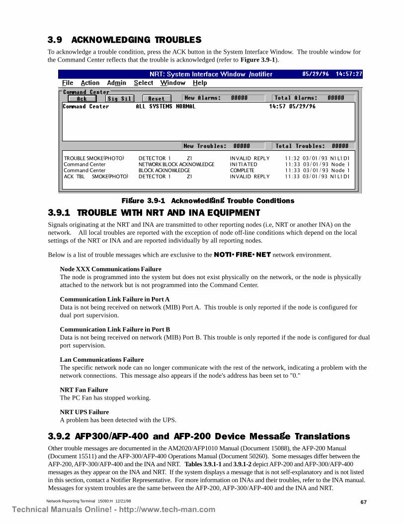
Network Reporting Terminal 15090:H 12/21/98 67
3.9 ACKNOWLEDGING TROUBLESTo acknowledge a trouble condition, press the ACK button in the System Interface Window. The trouble window forthe Command Center reflects that the trouble is acknowledged (refer to Figure 3.9-1).
Figure 3.9-1 Acknowledging Trouble Conditions
3.9.1 TROUBLE WITH NRT AND INA EQUIPMENTSignals originating at the NRT and INA are transmitted to other reporting nodes (i.e, NRT or another INA) on thenetwork. All local troubles are reported with the exception of node off-line conditions which depend on the localsettings of the NRT or INA and are reported individually by all reporting nodes.
Below is a list of trouble messages which are exclusive to the NOTI�FIRE�NET network environment.
Node XXX Communications FailureThe node is programmed into the system but does not exist physically on the network, or the node is physicallyattached to the network but is not programmed into the Command Center.
Communication Link Failure in Port AData is not being received on network (MIB) Port A. This trouble is only reported if the node is configured fordual port supervision.
Communication Link Failure in Port BData is not being received on network (MIB) Port B. This trouble is only reported if the node is configured for dualport supervision.
Lan Communications FailureThe specific network node can no longer communicate with the rest of the network, indicating a problem with thenetwork connections. This message also appears if the node's address has been set to "0."
NRT Fan FailureThe PC Fan has stopped working.
NRT UPS FailureA problem has been detected with the UPS.
3.9.2 AFP300/AFP-400 and AFP-200 Device Message TranslationsOther trouble messages are documented in the AM2020/AFP1010 Manual (Document 15088), the AFP-200 Manual(Document 15511) and the AFP-300/AFP-400 Operations Manual (Document 50260). Some messages differ between theAFP-200, AFP-300/AFP-400 and the INA and NRT. Tables 3.9.1-1 and 3.9.1-2 depict AFP-200 and AFP-300/AFP-400messages as they appear on the INA and NRT. If the system displays a message that is not self-explanatory and is not listedin this section, contact a Notifier Representative. For more information on INAs and their troubles, refer to the INA manual.Messages for system troubles are the same between the AFP-200, AFP-300/AFP-400 and the INA and NRT.
TROUBLE SMOKE(PHOTO) DETECTOR 1 Z1 INVALID REPLY 11:32 03/01/93 N1L1D1Command Center NETWORK BLOCK ACKNOWLEDGE INITIATED 11:33 03/01/93 Node 1Command Center BLOCK ACKNOWLEDGE COMPLETE 11:33 03/01/93 Node 1ACK TBL SMOKE(PHOTO) DETECTOR 1 Z1 INVALID REPLY 11:33 03/01/93 N1L1D1
Technical Manuals Online! - http://www.tech-man.com

Network Reporting Terminal 15090:H 12/21/9868
Table 3.9.1-1 AFP-200 Device Messages as They Appear on the INA and NRT (page 1 of 2)
AFP-200Type I.D. AFP-200 Message INA LCD Message NRT Message
Supervisory
activated: ACTIVESUPERVISORY custom pointlabel ZONE 04 01:40P10/26/95 M04
trouble: TROUBLSUPERVISORY custom pointlabel Z04 OPEN CIRCUIT02:07P 10/26/95 M04
activated: TROUBL N012SPSU custom point labelZ004 SPRNKLR TROUBLE01:51P 10/26/95 104
trouble: TROUBL N012 SPSUcustom point label Z004OPEN CIRCUIT 02:07P10/26/95 104
activated:: TROUBL SPRNKLRMNTR custom point label Z4SPRNKLR TROUBLE 13:4910/26/95 N12LIM4
trouble: TROUBL SPRNKLRMNTR custom point label Z4open circuit 14:06 10/26/95N12LIM4
Tamper
activated: ACTIVE TAMPERcustom point label ZONE 0402:20P 10/26/95 M05
trouble: TROUBL TAMPERcustom point label Z04OPEN CIRCUIT 02:43P10/26/95 M05
activated: TROUBL N012SPSU custom point labelZ004 SPRNKLR TROUBLE02:22P 10/26/95 105
trouble: TROUBL N012 SPSUcustom point label Z004OPEN CIRCUIT 02:43P10/26/95 105
activated: TROUBL SPRNKLRMNTR custom point label Z4SPRNKLR TROUBLE 14:2010/26/95 N12LIM5
trouble: TROUBL SPRNKLRMNTR custom point label Z4OPEN CIRCUIT 14:41 10/26/95N12LIM5
Non-Fire
activated: ACTIVE NONFIREcustom point label ZONE 0402:07P 11/07/95 M06
trouble: TROUBL NON FIREcustom point label Z04OPEN CIRCUIT 02:21P11/07/95 M06
activated: ACTIVE N012 NOAcustom point label ZONE 0401:12P 11/07/95 106
trouble: TROUBL N012 NOAcustom point label Z004OPEN CIRCUIT 01:28P11/07/95 106
activated: *ACTIVE NONALARM custom point label Z413:10 11/07/95 N12LIM6
trouble: TROUBL NON ALARMcustom point label Z4 OPENCIRCUIT 13:31 11/07/95N12LIM6
Hazard Alert
activated: ACTIVE HAZARDALERT custom point labelZONE 04 02:33P 11/07/95M07
trouble: TROUBL HAZARDALERT custom point labelZ04 OPEN CIRCUIT 02:47P11/07/95 M07
activated: TROUBL N012SPSU custom point labelZ004 SPRNKLR TROUBLE01:39P 11/07/95 107
trouble: TROUBL N012 SPSUcustom point label Z004OPEN CIRCUIT 01:52P11/07/95 107
activated: TROUBL SPRNKLRMNTR custom point label Z4SPRNKLR TROUBLE 13:3611/07/95 N12LIM7
trouble: TROUBL SPRNKLRMNTR custom point label Z4OPEN CIRCUIT 13:49 11/07/95N12LIM7
Fire Control
activated: ACTIVE FIRECONTROL custom pointlabel ZONE 04 03:21P11/07/95 M08
trouble: TROUBL FIRECONTROL custom pointlabel Z04 OPEN CIRCUIT03:35P 11/07/95 M08
activated: ACTIVE N012NONA custom point labelZONE 04 02:26P 11/07/95108
trouble: TROUBL N012 NONAcustom point label Z004OPEN CIRCUIT 02:33P11/07/95 108
activated: *ACTIVE NON ALMMON custom point label ZONE04 14:23 11/07/95 N12LIM8
trouble: TROUBL NON ALMMON custom point label Z4OPEN CIRCUIT 14:31 11/07/95N12LIM8
Abort Switch
activated: ACTIVE ABORTSWITCH custom point labelZONE 91 03:07P 11/07/95M09
trouble: TROUBL ABORTSWITCH custom point labelZ91 OPEN CIRCUIT 04:17P11/07/95 M09
activated: ACTIVE N012NONA custom point labelZONE 91 03:12P 11/07/95109
trouble: TROUBL N012 NONAcustom point label Z091OPEN CIRCUIT 03:22P11/07/95 109
activated: *ACTIVE NON ALMMON custom point label ZONE91 15:10 11/07/95 N12LIM9
trouble: TROUBL NON ALMMON custom point label Z91OPEN CIRCUIT 15:19 11/07/95N12LIM9
Man.Release
activated: ALARM: MAN.RELEASE custom point labelZONE 91 04:34P 11/07/95M10
trouble: TROUBL MAN.RELEASE custom point labelZ91 OPEN CIRCUIT 04:58P11/07/95 M10
activated: ALARM: N012MON custom point labelZONE 91 03:38P 11/07/95110
trouble: TROUBL N012 MONcustom point label Z091OPEN CIRCUIT 04:02P11/07/95 110
activated: ALARM: MONITORcustom point label ZONE 9115:36 11/07/95 N12LIM10
trouble: TROUBL MONITORcustom point label Z91 OPENCIRCUIT 16:00 11/07/95N12LIM10
Trouble Mon
activated: TROUBLTROUBLE MON custom pointlabel Z04 SHORT CIRCUIT08:24A 11/08/95 M12
trouble: TROUBL TROUBLEMON custom point label Z04OPEN CIRCUIT 08:36A11/08/95 M12
activated: TROUBL N012MTRB custom point labelZ004 SHORT CIRCUIT 07:29A11/08/95 112
trouble: TROUBL N012 MTRBcustom point label Z004OPEN CIRCUIT 07:43A11/08/95 112
activated: TROUBL TRBLMONITOR custom point labelZ4 SHORT CIRCUIT 07:2711/08/95 N12LIM12
trouble: TROUBL TRBLMONITOR custom point labelZ4 OPEN CIRCUIT 07:3911/08/95 N12LIM12
*Will only print out in ACTIVE HISTORY BUFFER portion of NRT.
Technical Manuals Online! - http://www.tech-man.com

Network Reporting Terminal 15090:H 12/21/98 69
Table 3.9.1-1 AFP-200 Device Messages as They Appear on the INA and NRT (page 2 of 2)
Refer to the AM2020/AFP1010 Manual, Document 15088, for a description of AM2020/AFP1010 Messages.
AFP-200Type I.D.
AFP-200Message
INA LCDMessage
NRTMessage
Burglar Ala
activated: ACTIVEBURGLAR ALA custompoint label ZONE 04 08:52A11/08/95 M13
trouble: ACTIVE BURGLARALA custom point labelZONE 04 09:33A 11/08/95M13
activated: TROUBL N012SARM custom point label Z004SECURITY TAMPER 07:57A11/08/95 113
trouble: TROUBL N012 SARMcustom point label Z004SECURITY TAMPER 08:40A11/08/95 113
activated: TROUBL AREAMONITOR custom point labelZ4 SECURITY TAMPER 07:5511/08/95 N12LIM13
trouble: TROUBL AREAMONITOR custom point labelZ4 SECURITY TAMPER 08:3811/08/95 N12LIM13
Silence
activated: ACTIVE SILENCEcustom point label ZONE04 11:34A 11/08/95 M14
trouble: TROUBL SILENCEcustom point label Z04OPEN CIRCUIT 11:45A11/08/95 M14
activated: ACTIVE N012 NONAcustom point label ZONE 0410:43A 11/08/95 114
trouble: TROUBL N012 NONAcustom point label Z004 OPENCIRCUIT 10:51A 11/08/95 114
activated: *ACTIVE NONALM MON custom point labelZONE 04 10:59 11/08/95N12LIM14
trouble: TROUBL NON ALMMON custom point label Z4OPEN CIRCUIT 10:4811/08/95 N12LIM14
Pas Inhibit
activated: ACTIVE PASINHIBIT custom point labelZONE 04 12:04P 11/08/95M15
trouble: TROUBL PASINHIBIT custom point labelZ04 OPEN CIRCUIT 12:10P11/08/95 M15
activated: ACTIVE N012 NONAcustom point label ZONE 0411:08A 11/08/95 115
trouble: TROUBL N012 NONAcustom point label Z004 OPENCIRCUIT 11:16A 11/08/95 115
activated: *ACTIVE NONALM MON custom point labelZONE 04 11:06 11/08/95N12LIM15
trouble: TROUBL NON ALMMON custom point label Z4OPEN CIRCUIT 11:1411/08/95 N12LIM15
SystemReset
activated: ACTIVE SYSTEMRESET custom point labelZONE 04 12:21P 11/08/95M16
trouble: TROUBL SYSTEMRESET custom point labelZ04 OPEN CIRCUIT 12:39P11/08/95 M16
activated: ACTIVE N012 NONAcustom point label ZONE 0411:26A 11/08/95 116
trouble: TROUBL N012 NONAcustom point label Z004 OPENCIRCUIT 11:44A 11/08/95 116
activated: COMMANDCENTER SYSTEM RESETACTIVATED 11:24 11/08/95N12
trouble: TROUBL NON ALMMON custom point label Z4OPEN CIRCUIT 11:4211/08/95 N12LIM16
SmokeDetect
activated: ALARM: SMOKEDETECT custom point labelZONE 04 12:46P 11/08/95M17
trouble: TROUBL SMOKEDETECT custom point labelZ04 OPEN CIRCUIT 02:06P11/28/95 M17
activated: ALARM: N012 MONcustom point label ZONE 0411:54A 11/08/95 117
trouble: TROUBL N012 MONcustom point label Z004 OPENCIRCUIT 01:11P 11/08/95 117
activated: : ALARM:MONITOR custom point labelZONE 04 11:53 11/08/95N12LIM17
trouble: TROUBL MONITORcustom point label Z4 OPENCIRCUIT 13:09 11/08/95N12LIM17
Heat Detect
activated: ALARM: HEATDETECT custom point labelZONE 04 02:16P 11/08/95M18
trouble: TROUBL HEATDETECT custom point labelZ04 OPEN CIRCUIT 02:26P11/08/95 M18
activated: ALARM: N012 MONcustom point label ZONE 0401:21P 11/08/95 118
trouble: TROUBL N012 MONcustom point label Z004 OPENCIRCUIT 01:31P 11/08/95 118
activated: ALARM:MONITOR custom point labelZONE 04 13:19 11/08/95N12LIM18
trouble: TROUBL MONITORcustom point label Z4 OPENCIRCUIT 13:29 11/08/95N12LIM18
Water Flow
activated: ALARM:WATERFLOW custom pointlabel ZONE 04 03:18P11/08/95 M19
trouble: TROUBLWATERFLOW custom pointlabel Z04 OPEN CIRCUIT03:28P 11/08/95 M19
activated: ALARM: N012 WATcustom point label ZONE 0402:21P 11/08/95 119
trouble: TROUBL N012 WATcustom point label Z004 OPENCIRCUIT 02:33P 11/08/95 119
activated: ALARM: WATERFLOW custom point labelZONE 04 14:19 11/08/95N12LIM19
trouble: TROUBL WATERFLOW custom point label Z4OPEN CIRCUIT 14:3111/08/95 N12LIM19
Pre-Alarm
activated: PREALM SMOKE(PHOTO) custom point labelALERT: 1.31/1.50% 05:21P11/08/95 D01
trouble: (not applicable)
activated: TROUBL N012PHOT AFP200 PREALM ALERTZ091 MAINTENANCE REQ04:29P 11/08/95 101
trouble: (not applicable)
activated: TROUBL SMOKE(PHOTO) AFP200 PREALMALERT Z91 MAINTENANCEREQ 16:23 11/08/95N12LID1
trouble: (not applicable)
*Will only print out in ACTIVE HISTORY BUFFER portion of NRT.
Technical Manuals Online! - http://www.tech-man.com

Network Reporting Terminal 15090:H 12/21/9870
/003-PFA004-PFA.D.IepyT
004-PFA/003-PFAegasseM
DCLANIegasseM
TRNegasseM
ekomStceteD
:MRALA:)trohs(mrala EKOMSTCETED enozlebalecived
121M79/70/50p72:10lebal
EKOMSELBUORT:elbuort50ZlebalecivedTCETED
p72:10YLPERDILAVNI121M79/70/50
trohs(mrala MRALA:): 232NenozlebalecivedKMSM12179/70/50p72:10lebal
232NELBUORT:elbuort500ZlebalecivedKMSM
p72:10YLPERDILAVNI12179/70/50
:MRALA:)trohs(mrala EKOMSTCETED lebalenozlebalecived
12M1L232N79/70/50p72:10
EKOMSELBUORT:elbuortDILAVNI5ZlebalecivedTCETED
79/70/50p72:10YLPER12M1L232N
taeHtceteD
TAEH:MRALA:)trohs(mralaenozlebalecivedTCETED121M79/70/50p72:10lebal
TAEHLBUORT:elbuort50ZlebalecivedTCETED
p72:10YLPERDILAVNI121M79/70/50
232N:MRALA:)trohs(mralalebalenozlebalecivedTHM
12179/70/50p72:10
THM232NLBUORT:elbuortDILAVNI500Zlebalecived
12179/70/50p72:10YLPER
TAEH:MRALA:)trohs(mralalebalenozlebalecivedTCETED
12M1L232N79/70/50p72:10
TCETEDTAEHLBUORT:elbuortYLPERDILAVNI5Zlebalecived
12M1L232N79/70/50p72:10
lluPnoitatS
LLUP:MRALA:)trohs(mralaenozlebalecivedNOITATS
121M79/70/50p72:10lebal
LLUPLBUORT:elbuort50ZlebalecivedNOITATS
p72:10YLPERDILAVNI121M79/70/50
232N:MRALA:)trohs(mralalebalenozlebalecivedLLUP
12179/70/50p72:10
LLUP232NLBUORT:elbuortDILAVNI500Zlebalecived
12179/70/50p72:10YLPER
LLUP:MRALA:)trohs(mralalebalenozlebalecivedNOITATS
12M1L232N79/70/50p72:10
NOITATSLLUPLBUORT:elbuortYLPERDILAVNI5Zlebalecived
12M1L232N79/70/50p72:10
rotinoM
:MRALA:)trohs(mralaenozlebalecivedROTINOM
121M79/70/50p72:10lebal
ROTINOMLBUORT:elbuortDILAVNI50Zlebalecived
121M79/70/50p72:10YLPER
232N:MRALA:)trohs(mralalebalenozlebalecivedNOM
12179/70/50p72:10
NOM232NLBUORT:elbuortDILAVNI500Zlebalecived
12179/70/50p72:10YLPER
ROTINOM:MRALA:)trohs(mralap72:10lebalenozlebalecived
12M1L232N79/70/50
ROTINOMLBUORT:elbuortYLPERDILAVNI5Zlebalecived
12M1L232N79/70/50p72:10
)knalb(
ecived:MRALA:)trohs(mralap72:10lebalenozlebal
121M79/70/50
lebalecivedLBUORT:elbuortp72:10YLPERDILAVNI50Z
121M79/70/50
232N:MRALA:)trohs(mralalebalenozlebalecived
12179/70/50p72:10
232NLBUORT:elbuortDILAVNI500Zlebalecived
12179/70/50p72:10YLPER
lebalecivedMRALA:)trohs(mrala79/70/50p72:10lebalenoz
12M1L232N
5ZlebalecivedLBUORT:elbuort79/70/50p72:10YLPERDILAVNI
12M1L232N
trobAhctiwS
TROBAEVITCA:)trohs(mralalebalenozlebalecivedHCTIWS
121M79/70/50p72:10
TROBALBUORT:elbuort50ZlebalecivedHCTIWSp72:10YALPERDILAVNI
121M79/70/50
22NEVITCA:)trohs(mralalebalenozlebalecivedwsba
12179/70/50p72:10
232NLBUORT:elbuort500ZlebalecivedWSBA
p72:10YLPERDILAVNI12179/70/50
TROBAEVITCA:trohsmralalebalenozlebalecivedHCTIWS
12M1L232N79/70/50p72:10
TROBALBUORT:elbuortDILAVNI5ZlebalecivedHCTIWS
79/70/50p72:10YLPER12M1L232N
.naMesaeleR
.NAM:MRALA:)trohs(mralaenozlebalecivedESAELER121M79/70/50p72:10lebal
.NAMLBUORT:elbuort50ZlebalecivedESAELER
p72:10YLPERDILAVNI121M79/70/50
232N:MRALA:)trohs(mralaenozlebalecivedRNAM
12179/70/50p72:10lebal
232NLBUORT:elbuort500ZlebalecivedRNAM
p72:10YLPERDILAVNI12179/70/50
.NAM:MRALA:)trohs(mralalebalenozlebalecivedESAELER
12M1L232N79/70/50p72:10
.NAMLBUORT:elbuort5ZlebalecivedESAELER
79/70/50p72:10YLPERDILAVNI12M1L232N
Table 3.9.1-2 AFP300/AFP-400 Device Messages as They Appear on the INA and NRT(page 1 of 5)
Technical Manuals Online! - http://www.tech-man.com

Network Reporting Terminal 15090:H 12/21/98 71
/003-PFA004-PFA.D.IepyT
003-PFA/004-PFAegasseM
DCLANIegasseM
TRNegasseM
ecneliS
EVITCA:)trohs(mralalebalecivedECNELIS
79/70/50p04:21lebalenoz121M
ECNELISLBUORT:elbuortDILAVNI50Zlebalecived
79/70/50p04:21YLPER121M
232NEVITCA:)trohs(mralalebalenozlebalecivedLIS
12179/70/50p04:21
LIS232NLBUORT:elbuortDILAVNI500Zlebalecived
12179/70/50p04:21YLPER
EVITCA:)trohs(mralaenozlebalecivedECNELIS
79/70/50p04:21lebal12M1L232N
ECNELISLBUORT:elbuotDILAVNI5Zlebalecived79/70/50p04:21YLPER
12M1L232N
teseRmetsyS
EVITCA:)trohs(mralaecivedTESERMETSYS
p04:21lebalenozlebal121M79/70/50
METSYSLBUORT:elbuort50ZlebalecivedTESER
p04:21YLPERDILAVNI121M79/70/50
232NEVITCA:)trohs(mralalebalenozlebalecivedTSRS
12179/70/50p04:21
232NLBUORT:elbuort500ZlebalecivedTSRSp04:21YLPERDILAVNI
12179/70/50
EVITCA:)trohs(mralaecivedTESERMETSYS
p04:21lebalenozlebal12M1L232N79/70/50
METSYSLBUORT:elbuort5ZlebalecivedTESER
DILAVNI YLPER p04:2112M1L232N79/70/50
ytiruceS
:)nepodnatrohs(mralaecivedYTIRUCESEVITCA
p04:21lebalenozlebal121M79/70/50
LBUORT:elbuortlebalecivedYTIRUCES
YLPERDILAVNI50Z121M79/70/50p04:21
:)nepodnatrohs(mralaecivedUCES232NLBUORT
YTIRUCES500Zlebal79/70/50p04:21MRALA
121
232NLBUORT:elbuort500ZlebalecivedUCES
p04:21YLPERDILAVNI12179/70/50
:)nepodnatrohs(mralaecivedYTIRUCESLBUORTMRALAYTIRUCES5Zlebal
79/70/50p04:2112M1L232N
YTIRUCESLBUORT:elbuortDILAVNI5Zlebalecived79/70/50p04:21YLPER
12M1L232N
NOMelbuorT
LBUORT:)trohs(mralaecivedNOMELBUORT
TIUCRICTROHS50Zlebal121M79/70/50p04:21
LBUORT:elbuortecivedNOMELBUORT
YLPERDILAVNI50Zlebal121M79/70/50p04:21
232NLBUORT:)trohs(mrala500ZlebalecivedBRTMp04:21TIUCRICTROHS
12179/70/50
232NLBUORT:elbuort500ZlebalecivedBRTM
p04:21YLPERDILAVNI12179/70/50
LBUORT:)trohs(mralalebalecivedNOMELBUORT
p04:21TIUCRICTROHS5Z12M1L232N79/70/50
ELBUORTLBUORT:elbuort5ZlebalecivedNOM
p04:21YLPERDILAVNI12M1L232N79/70/50
tibihnISAP
SAPEVITCA:)trohs(mralaenozlebalecivedTIBIHNI
79/70/50p04:21lebal121M
SAPLBUORT:elbuort50ZlebalecivedTIBIHNIp04:21YLPERDILAVNI
121M79/70/50
232NEVITCA:)trohs(mralalebalenozlebalecivedISAP
12179/70/50p04:21
ISAP232NLBUORT:elbuortDILAVNI500Zlebalecived
79/70/50p04:21YLPER121
SAPEVITCA:)trohs(mralaenozlebalecivedTIBIHNI
79/70/50p04:21lebal12M1L232N
SAPLBUORT:elbuort5ZlebalecivedTIBIHNIp04:21YLPERDILAVNI
12M1L232N79/70/50
egaPllaCllA
EVITCA:)trohs(mralaecivedEGAPLLACLLA
p04:21lebalenozlebal121M79/70/50
LLACLLALBUORT:elbuort50ZlebalecivedEGAPp04:21YLPERDILAVNI
121M79/70/50
232NEVITCA:)trohs(mralaenozlebalecivedGPLA
12179/70/50p04:21lebal
232NLBUORT:elbuort500ZlebalecivedGPLA
p04:21YLPERDILAVNI12179/70/50
EVITCA:)trohs(mralalebalecivedEGAPLLACLLA
79/70/50p04:21lebalenoz12M1L232N
LLACLLALBUORT:elbuort50ZlebalecivedEGAPp04:21YLPERDILAVNI
12M1L232N79/70/50
repmaT
EVITCA:)trohs(mralaenozlebalecivedREPMAT
79/70/50p04:21lebal121M
REPMATLBUORT:elbuortDILAVNI50Zlebalecived
79/70/50p04:21YLPER121M
232NLBUORT:)trohs(mralalebalecivedPMAT
ELBUORTRELKNIRPS12179/70/50p04:21
232NLBUORT:elbuort500ZlebalecivedPMAT
p04:21YLPERDILAVNI12179/70/50
LBUORT:)trohs(mralalebalecivedREPMATELBUORTRELKNIRPS
79/70/50p04:2112M1L232N
ecivedREPMAT:elbuortYLPERDILAVNI50Zlebal
12M1L232N79/70/50p04:21
lortnoCeriF
ERIFEVITCA:)trohs(mralalebalecivedLORTNOC
79/70/50p04:21lebalenoz121M
ERIFLBUORT:elbuortlebalecivedLORTNOC
p04:21DILAVNI50Z121M79/70/50
232NEVITCA:)trohs(mralaenozlebalecivedNOCF
12179/70/50p04:21lebal
232NELBUORT:elbuort500ZlebalecivedNOCF
p04:21YLPERDILAVNI12179/70/50
ERIFEVITCA:)trohs(mralaenozlebalecivedLORTNOC
79/70/50p04:21lebal12M1L232N
ERIFLBUORT:elbuort50ZlebalecivedLORTNOC
p04:21YLPERDILAVNI12M1L232N79/70/50
Table 3.9.1-2 AFP-300/AFP-400 Messages as They Appear on the INA and NRT (page 2 of 5)
Technical Manuals Online! - http://www.tech-man.com

Network Reporting Terminal 15090:H 12/21/9872
Table 3.9.1-2 AFP-300/AFP-400 Device Messages as they Appear on the INA and NRT (page 3 of 5)
/003-PFA004-PFA.D.IepyT
004-PFA/003-PFAegasseM
DCLANIegasseM
TRNegasseM
egaP.eleT
EVITCA:)trohs(mralalebalecivedEGAP.ELET
P51:30lebalenoz121M79/70/50
.ELETLBUORT:elbuort50ZlebalecivedEGAP
P51:3YLPERDILAVNI121M79/70/50
EVITCA:)trohs(mralalebalecivedGPLT232N
P51:3lebalenoz12179/70/50
232NLBUORT:elbuort500ZlebalecivedGPLT
P51:3YLPERDILAVNI12179/70/50
.ELETEVITCA:)trohs(mralaenozlebalecivedEGAP
79/70/50P51:3lebal12M1L232N
ELETLBUORT:elbuort50ZlebalecivedEGAP
P51:3YLPERDILAVNI12M1L232N79/70/50
rotinoM.bmoC
:MRALA:)trohs(mralaecivedROTINOM.BMOC
P51:3lebalenozlebal121M79/70/50
.BMOCLBUORT:elbuortlebalecivedROTINOM
YLPERDILAVNI50Z121M79/70/50P51:3
:MRALA:)trohs(mralaecivedBMOC232N
P51:3lebalenozlebal12179/70/50
232NLBUORT:elbuort500ZlebalecivedBMOC
P51:3YLPERDILAVNI12179/70/50
:MRALA:)trohs(mralaecivedROTINOMBMOC
P51:3lebalenozlebal12M1L232N79/70/50
.BMOCLBUORT:elbuort50ZlebalecivedROTINOM
P51:3YLPERDILAVNI12M1L232N79/70/50
sySrelknirpS
:MRALA:)trohs(mralaecivedSYSRELKNIRPS
P51:3lebalenozlebal121M79/70/50
LBUORT:elbuortecivedSYSRLKNIRPS
YLPERDILAVNI50Zlebal121M79/70/50P51:3
:MRALA:)trohs(mralalebalecivedUSPS232N
P51:3lebalenoz12179/70/50
232NLBUORT:elbuort500ZlebalecivedUSPS
P51:3YLPERDILAVNI12179/70/50
:MRALA:)trohs(mralaecivedSYSRELKNIRPS
P51:3lebalenozlebal12M1L232N79/70/50
RLKNIRPSLBUORT:elbuort50ZlebalecivedSYSP51:3YLPERDILAVNI
12M1L232N79/70/50
tohSdnoceS
EVITCA:)trohs(mralaecivedTOHSDNOCES
79/70/50P51:3lebalenoz121M
LBUORT:elbuortecivedTOHSDNOCES
YLPERDILAVNI50Zlebal121M79/70/50P51:3
EVITCA:)trohs(mralalebalecivedHSPS232N
P51:3lebalenoz12179/70/50
232NLBUORT:elbuort500ZlebalecivedHSDS
P51:3YLPERDILAVNI12179/70/50
EVITCA:)trohs(mralaecivedTOHSDNOCES
lebalenozlebal12M1L232N
DNOCESLBUORT:elbuort50ZlebalecivedTOHSP51:3YLPERDILAVNI
12M1L232N79/70/50
yalDleRnaM
:MRALA:)trohs(mralaecivedYALDLERNAM
P51:3lebalenozlebal121M79/70/50
NAMLBUORT:elbuortlebalecivedYALDLER
YLPERDILAVNI50Z121M79/70/50P51:3
:MRALA:)trohs(mralalebalecivedLDRM232N
P51:3lebalenoz12179/70/50
232NLBUORT:elbuort500ZlebalecivedLDRM
P51:3YLPERDILAVNI12179/70/50
NAM:MRALA:)trohs(mralaenozlebalecivedYALDLER
79/70/50P51:3lebal12M1L232N
LERNAMLBUORT:elbuort50ZlebalecivedYALDP51:3YLPERDILAVNI
12M1L232N79/70/50
trelAdrazaH
EVITCA:)trohs(mralaecivedTRELADAZAH
P51:3lebalenozlebal121M79/70/50
LBUORT:elbuortecivedTRELADRAZAH
YLPERDILAVNI50Zlebal121M79/70/50P51:3
LBUORT:)trohs(mralalebalecivedAZAH232N
LBUORTRLKNIRPS12179/70/50P51:3
232NLBUORT:elbuort500ZlebalecivedAZAH
P51:3YLPERDILAVNI12179/70/50
LBUORT:)trohs(mralaecivedTRELADRAZAH
LBUORTRLKNIRPSlebal12M1L232N79/70/50P51:3
DRAZAHLBUORT:elbuort50ZlebalecivedTRELA
P51:3YLPERDILAVNI12M1L232N79/70/50
yrosivrepuS
EVITCA:)trohs(mralaecivedYROSIVREPUS
P51:3lebalenozlebal121M79/70/50
LBUORT:elbuortecivedYROSIVREPUS
YLPERDILAVNI50Zlebal121M79/70/50P51:3
LBUORT:)trohs(mralalebalecivedRPUS232N
LBUORTRLKNIRPS12179/70/50P51:3
232NLBUORT:elbuort500ZlebalecivedRPUS
P51:3YLPERDILAVNI12179/70/50
LBUORT:)trohs(mralalebalecivedYROSIVREPUS
P51:3LBUORTRLKNIRPS12M1L232N79/70/50
LBUORT:elbuortlebalecivedYROSIVREPUS
P51:3YLPERDILAVNI5Z12M1L232N79/70/50
wolfretaW
:MRALA:trohsmralaecivedWOLFRETAWP51:3lebalenozlebal
121M79/70/50
LBUORT:elbuortecivedWOLFRETAW
YLPERDILAVNI50Zlebal121M79/70/50P51:3
:MRALA:)trohs(mralalebalecivedTAW232N
P51:3lebalenoz12179/70/50
RETAWLBUORT:elbuort500ZlebalecivedWOLF
P51:3YLPERDILAVNI12179/70/50
:MRALA:)trohs(mralalebalecivedWOLFRETAW
79/70/50P51:3lebalenoz12M1L232N
RETAWLBUORT:elbuort5ZlebalecivedWOLFP51:3YLPERDILAVNI
12M1L232N79/70/50
Technical Manuals Online! - http://www.tech-man.com

Network Reporting Terminal 15090:H 12/21/98 73
Table 3.9.1-2 AFP-300/AFP-400 Device Messages as They Appear on the INA and NRT (page 4 of 5)
/003-PFA004-PFA.D.IepyT
004-PFA/003-PFAegasseM
DCLANIegasseM
TRNegasseM
lortnoC
*noitaicnunnAoN:no
LBUORT:elbuortlebalecivedLORTNOC
YLPERDILAVNI50Z101M79/61/5P70:21
004PF232NEVITCA:noP70:21ECIVEDTUPTUO
10179/61/5
232NLBUORT:elbuort500ZlebalecivedNOCP70:21YLPERDILAVNI
10179/61/5
004PFAEVITCA:noP70:21ECIVEDTUPTUO
1M1L232N79/61/5
LBUORT:elbuort5ZlebalecivedLORTNOC
P70:21YLPERDILAVNI1M1L232N79/61/5
yaleR
*noitaicnunnAoN:no
LBUORT:elbuort50ZlebalecivedYALER
DILAVNI
004PFA232NEVITCA:noP70:21ECIVEDTUPTUO
10179/61/5
232NLBUORT:elbuort500ZlebalecivedLERP70:21YLPERDILAVNI
10179/61/5
004PFAEVITCA:noP70:21ECIVEDTUPTUO
1M1L232N79/61/5
YALERLBUORT:elbuortDILAVNI5Zlebalecived79/61/5P70:21YLPER
1M1L232N
tiucriClleB
*noitaicnunnAoN:no
LLEBLBUORT:elbuortlebalecivedTIUCRIC
YLPERDILAVNI50Z101M79/61/5P70:21
004PFA232NEVITCA:noP70:21ECIVEDTUPTUO
10179/61/5
232NLBUORT:elbuort500ZlebalecivedLLEBP70:21YLPERDILAVNI
10179/61/5
004PFAEVITCA:noP70:21ECIVEDTUPTUO
1M1L232N79/61/5
LLEBLBUORT:elbuort5ZlebalecivedTIUCRIC
P70:21YLPERDILAVNI1M1L232N79/61/5
tkCebortS
*noitaicnunnAoN:no
LBUORT:elbuortecivedTKCEBORTS
DILAVNI50Zlebal79/61/5P70:21YLPER
101M
004PFA232NEVITCA:noP70:21ECIVEDTUPTUO
10179/61/5
232NLBUORT:elbuort500ZlebalecivedCRTS
P70:21YLPERDILAVNI10179/61/5
004PFAEVITCA:noP70:21ECIVEDTUPTUO
1M1L232N79/61/5
EBORTSLBUORT:elbuort5ZlebalecivedTKC
P70:21YLPERDILAVNI1M1L232N79/61/5
tiucriCnroH
*noitaicnunnAoN:no
NROHLBUORT:elbuortlebalecivedTIUCRIC
YLPERDILAVNI50Z101M79/61/5P70:21
004PFA232NEVITCA:noP70:21ECIVEDTUPTUO
10179/61/5
232NLBUORT:elbuort500ZlebalecivednroHP70:21YLPERDILAVNI
10179/61/5
004PFAEVITCA:noP70:21ECIVEDTUPTUO
1M1L232N79/61/5
NROHLBUORT:elbuort5ZlebalecivedTIUCRIC
P70:21YLPERDILAVNI1M1L232N79/61/5
tkCelbiduA
*noitaicnunnAoN:no
LBUORT:elbuortecivedTKCELBIDUA
DILAVNI50Zlebal79/61/5P70:21YLPER
101M
004PFA232NEVITCA:noP70:21ECIVEDTUPTUO
10179/61/5
232NLBUORT:elbuort500ZlebalecivedBDUA79/61/5P70:21DILAVNI
101
004PFAEVITCA:noP70:21ECIVEDTUPTUO
1M1L232N79/61/5
LBUORT:elbuortecivedTKCELBIDUA
YLPERDILAVNI5Zlebal79/61/5P70:21
1M1L232N
lleBdnEleR
*noitaicnunnAoN:no
LERLBUORT:elbuortlebalecivedLLEBDNE
YLPERDILAVNI1RZ101M79/61/5P70:21
004PFA232NEVITCA:noP70:21ECIVEDTUPTUO
10179/61/5
232NLBUORT:elbuortZlebalecivedLBER
P70:21YLPERDILAVNI10179/61/5
004PFAEVITCA:noP70:21ECIVEDTUPTUO
1M1L232N79/61/5
LERLBUORT:elbuortZlebalecivedLLEBDNE
P70:21YLPERDILAVNI1M1L232N79/61/5
tkCesaeleR
*noitaicnunnAoN:no
LBUORT:elbuortecivedTKCESAELER
DILAVNI1RZlebal79/61/5P70:21YLPER
101M
004PFA232NEVITCA:noP70:21ECIVEDTUPTUO
10179/61/5
232NLBUORT:elbuortZlebalecivedTKCR
P70:21YLPERDILAVNI10179/61/5
004PFAEVITCA:noP70:21ECIVEDTUPTUO
1M1L232N79/61/5
LBUORT:elbuortecivedTKCESAELERYLPERDILAVNIZlebal
79/61/5P70:211M1L232N
.ylno,reffuByrotsiHehtnideyalpsideblliw'noitaicnunnAoN'yastahtsegassem004--PFA/003PFAllA*
Technical Manuals Online! - http://www.tech-man.com

Network Reporting Terminal 15090:H 12/21/9874
/003-PFA004-PFA.D.IepyT
004-PFA/003-PFAegasseM
DCLANIegasseM
TRNegasseM
clUtkCleR
*noitaicnunnAoN:no
LERLBUORT:elbuortlebalecivedCLUTKC
YLPERDILAVNI1RZ101M79/61/50P55:40
004PFA232NEVITCA:noP55:40ECIVEDTUPTUO
10179/61/50
232NLBUORT:elbuortZlebalecivedCLUR
P55:40YLPERDILAVNI10179/61/50
004PFAEVITCA:noP55:40ECIVEDTUPTUO
1M1L232N79/61/50
TKCLERLBUORT:elbuortZlebalecivedCLU
P55:40YLPERDILAVNI1M1L232N79/61/50
elbiduAleR
*noitaicnunnAoN:no
LERLBUORT:elbuortlebalecivedELBIDUA
YLPERDILAVNI1RZ101M79/61/50P55:40
004PFA232NEVITCA:noP55:40ECIVEDTUPTUO
10179/61/50
232NLBUORT:elbuortZlebalecivedDUAR
P55:40YLPERDILAVNI10179/61/50
004PFAEVITCA:noP55:40ECIVEDTUPTUO
1M1L232N79/61/50
LERLBUORT:elbuortZlebalecivedELBIDUAP55:40YLPERDILAVNI
1M1L232N79/61/50
ltStesernoN
*noitaicnunnAoN:no
LBUORT:elbuortecivedLTCTESERNON
YLPERDILAVNI50Zlebal101M79/61/50P55:40
004PFA232NEVITCA:noP55:40ECIVEDTUPTUO
10179/61/50
232NLBUORT:elbuort500ZlebalecivedRNON
P55:40YLPERDILAVNI10179/61/50
004PFAEVITCA:noP55:40ECIVEDTUPTUO
1M1L232N79/61/50
LBUORT:elbuortecivedLTCTESERNONYLPERDILAVNI5Zlebal
79/61/50P55:401M1L232N
enohpeleT
*noitaicnunnAoN:no
LBUORT:elbuortlebalecivedENOHPELET
YLPERDILAVNI50Z101M79/61/50P55:40
004PFA232NEVITCA:noP55:40ECIVEDTUPTUO
10179/61/50
232NLBUORT:elbuort500ZlebalecivedELETP55:40YLPERDILAVNI
10179/61/50
004PFAEVITCA:noP55:40ECIVEDTUPTUO
1M1L232N79/61/50
LBUORT:elbuortlebalecivedENOHPELETP55:40YLPERDILAVNI5Z
1M1L232N79/61/50
lleBedoCleR
*noitaicnunnAoN:no
LERLBUORT:elbuortlebalecivedLLEBEDOC
1RZ
004PFA232NEVITCA:noP55:40ECIVEDTUPTUO
10B79/61/50
232NLBUORT:elbuort10RZlebalecivedLBCR
P55:40YLPERDILAVNI10B79/61/50
004PFAEVITCA:noP55:40ECIVEDTUPTUO
1B232N79/61/50
LERLBUORT:elbuortlebalecivedLLEBEDOC
YLPERDILAVNI1RZ1B232N79/61/50P55:40
eleRtnatsnI
*noitaicnunnAoN:no
TNATSNILBUORT:elbuort50ZlebalecivedELERP55:40YLPERDILAVNI
101M79/61/50
004PFA232NEVITCA:noP55:40ECIVEDTUPTUO
10179/61/50
232NLBUORT:elbuort500ZlebalecivedLERIP55:40YLPERDILAVNI
10179/61/50
004PFAEVITCA:noP55:40ECIVEDTUPTUO
1M1L232N79/61/50
ELERTNATSNI:elbuortDILAVNI5Zlebalecived79/61/50P55:40YLPER
1M1L232N
CmroFaeleR
*noitaicnunnAoN:no
AELERLBUORT:elbuortZlebalecivedCMROF
YLPERDILAVNI1R101M79/61/50P55:40
004PFA232NEVITCA:noP55:40ECIVEDTUPTUO
10179/61/50
232NLBUORT:elbuort10RZlebalecivedCMFR
P55:40YLPERDILAVNI10179/61/50
004PFAEVITCA:noP55:40ECIVEDTUPTUO
1M1L232N79/61/50
AELERLBUORT:elbuort1RZlebalecivedCMROF
P55:40YLPERDILAVNI1M1L232N79/61/50
rekaepS
*noitaicnunnAoN:no
LBUORT:elbuortlebalecivedREKAEPS
YLPERDILAVNI50Z101M79/61/50P55:40
004PFA232NEVITCA:noP55:40ECIVEDTUPTUO
10179/61/50
232NLBUORT:elbuort500ZlebalecivedRKPS
P55:40YLPERDILAVNI10179/61/50
004PFAEVITCA:noP55:40ECIVEDTUPTUO
1M1L232N79/61/50
LBUORT:elbuortlebalecivedREKAEPS
YLPERDILAVNI50Z79/61/50P55:40
1M1L232N
yrotsiHehtnideyalpsideblliw'noitaicnunnAoN'yastahtsegassem004PFA/003-PFAynA*.ylno,reffuB
Table 3.9.1-2 AFP-300/AFP-400 Device Messages as They Appear on the INA and NRT (page 5 of 5)
Technical Manuals Online! - http://www.tech-man.com

Network Reporting Terminal 15090:H 12/21/98 75
SECTION FOUR READ STATUSThe Read Status feature of the NRT allows the operator to display the status of nodes or devices communicating onand programmed into the NOTI�FIRE�NETNOTI�FIRE�NETNOTI�FIRE�NETNOTI�FIRE�NETNOTI�FIRE�NET. Only AM2020/AFP1010 devices are supported for read statusoperations in this software release.
DetectorsTo perform Read Status on a detector in the system, select the node the detector is connected to from the Select Systemdialog box. Press OK. A node dialog box appears. Press the Sensor button. Enter the address of the detector that isdesired to perform Read Status. Press OK. The Detector dialog box appears. This dialog box displays the currentprogramming for the detector, the verification counter, percentage of alarm, and whether the detector is in alarm,trouble, or disabled (refer to Figure 4.0-1).
Figure 4.0-2 Annunciator Point Read Status
Figure 4.0-1 Detector Read Status
Annunciator PointsTo perform Read Status on an annunciator point, press the Annunciator button from the Node dialog box. Enter theaddress of the point desired to perform Read Status. Press OK. The Annunciator Point dialog box displays. Thisdialog box shows the type of annunciator point and whether it is in Alarm, Trouble, or Off (refer to Figure 4.0-2).
These Boxes areChecked If theAnnunciator Pointis in Alarm,Trouble, or Off.
Toggle Buttonfor Disabling orEnabling a Point.
These Boxes areCheckedif a Detector isin Alarm, Trouble orDisabled.
Displays the numberof times a detectorhas gone throughthe verification cyclewithout going intoalarm.
Current Chamber readingas a percentage of alarm.
Technical Manuals Online! - http://www.tech-man.com

Network Reporting Terminal 15090:H 12/21/9876
Control and Monitor ModulesTo perform Read Status on a module in the system, select the node the module is connected to from the Select Systemdialog box. Press OK. A node dialog box will appear. Press the Module button. Enter the address of the moduledesired to perform Read Status. Press OK. The Module dialog box will appear. This dialog box displays the currentprogramming for the module and whether the module is in alarm, trouble, or disabled (refer to Figures 4.0-3 and 4.0-4).
These Boxes are Checked if a Moduleis in Alarm, Trouble, or Disabled.
Toggle Button for Disablingor Enabling a Point.
Figure 4.0-3 Monitor Module Read Status
These Boxes are Checked if a Moduleis in Active, Trouble, or Disabled.
Toggle Button for Activatingor Deactivating a Point.
Toggle Button for Disablingor Enabling a Point.
Figure 4.0-4 Control Module Read Status
Technical Manuals Online! - http://www.tech-man.com

Network Reporting Terminal 15090:H 12/21/98 77
AM2020/AFP1010 FACPsTo perform Read Status on the FACP, press the FACP button from the Node dialog box. The FACP dialog box displaysAlarm Verification Time, Signal Silence Inhibit Time, Signal Cut-Out Time, AVPS Installed, Zone boundary, miscella-neous FACP, NFPA Listings, LIB SLC loop and battery information (refer to Figure 4.0-5).
Figure 4.0-5 FACP Read Status
Technical Manuals Online! - http://www.tech-man.com

Network Reporting Terminal 15090:H 12/21/9878
ZonesTo perform Read Status on an AM2020/AFP1010 zone in the system, select the node the zone is connected to from theSelect System dialog box. Press OK. A node dialog box appears. Press the Zone button. Enter the zone numberdesired to perform Read Status. Press OK. The Zone dialog box will appear. This dialog box displays the currentprogramming for the zone and whether the zone is in alarm, trouble, or is disabled (refer to Figure 4.0-6).
These Boxes are Checked if a Zoneis in Alarm, Trouble, or Disabled.
Toggle Button forDisabling or Enablinga group of points.For an explanation ofthe group zonedisable feature, seethe AM2020/AFP1010Manual (Document15088).
Figure 4.0-6 Zone Read Status
PeripheralsTo perform Read Status on peripherals connected to the system, press the Peripherals button from the Node dialog box.The Peripherals dialog box will display information on terminals and printers (refer to Figure 4.0-7).
Figure 4.0-7 Peripheral Read Status
Toggle Button forDisabling or Enablinga Point.
Technical Manuals Online! - http://www.tech-man.com

Network Reporting Terminal 15090:H 12/21/98 79
SECTION FIVE
THE GRAPHIC PRESENTATION WINDOWThe Graphic Presentation Window allows the user to view floor plans of a building and locate devices in Alarm/Trouble, access information about the device, and perform Read Status.
Fire Alarms and Active InputsWhen a device goes into alarm or becomes activated, the symbol representing the device in the Graphic PresentationWindow turns red and flashes. When the alarm is acknowledged, it turns a darker shade of red and stops flashing.When the alarm or activation is cleared, the symbol returns to its original color.
TroublesWhen a device goes into trouble, the symbol representing the device in the Graphic Presentation Window turns brightyellow and flashes. When the trouble is acknowledged, the symbol turns a darker shade of yellow and stops flashing.When the trouble is cleared, the symbol returns to its original color.
SecurityWhen a security device goes into trouble, the symbol representing the device in the Graphic Presentation Windowturns bright blue and flashes. When the trouble is acknowledged, the symbol turns a darker shade of blue and stopsflashing. When the trouble is cleared, the symbol returns to its original color.
NOTEAfter a system reset, AFP-200 and AFP-300/AFP-400 FACPs do not send messages over the networkto clear alarms and the NRT continues to display any graphic icons mapped to an AFP-200 and AFP-300/AFP-400 in alarm or trouble. When the NRT receives a "System Reset Completed" message froman AFP-200 and AFP/300/AFP-400, it will then return the AFP-200 and AFP-300/AFP-400 activeicons to normal.
Technical Manuals Online! - http://www.tech-man.com

Network Reporting Terminal 15090:H 12/21/9880
5.1 ACCESSING INFORMATION ABOUT DEVICESUsing the Graphic Presentation Window, the user may access several screens which provide information about thatparticular device and the system as a whole.
For information regarding a specific device, position the mouse directly over the device and press the right mousebutton.
A pop-up menu will appear (refer to Figure 5.1-1).
Figure 5.1-1 Accessing the Pop-Up Menu
The Pop-Up MenuThe pop-up menu displays the system address followed by the five functions listed below:
• Information - displays a text file (user-programmable).• Picture - displays a graphic file (user-programmable).• Read Status/Program - accesses the Read Status Program dialog box.• Zoom In - displays next level screen (if defined).
The Video option under the pop-up menu is not available in this software release.
Scrolling Through ScreensIndividual screens can be viewed by pressing the keyboard arrow buttons. The right arrow button can be used to scroll
through all graphic screens.
Technical Manuals Online! - http://www.tech-man.com

Network Reporting Terminal 15090:H 12/21/98 81
APPENDIX AWINDOWS NT® SECURITY DISABLE
PROCEDURE
Disable ProcedureIn the Windows NT environment, a log-on box is displayed requesting a user name and password each time Windows®
NT starts up. The Windows NT log-on box may be disabled if the NRT software login function is sufficient for securityor if the NRT software is to start automatically once Windows NT is running. Once the NRT software starts, the usermust still choose LOGIN under the FILE menu and enter a user name and password to gain access to the NRT. Note: TheLogin function in the NRT software can not be eliminated. To eliminate the Windows NT log-on box, execute thefollowing steps:
1. From Program Manger, go to the FILE menu (for Windows NT® Version 4.0 users, select Start, then Run). SelectRUN and type regedt32. This brings up the Windows NT Registry.
2. Go to the HKEY_LOCAL_MACHINE dialog box.
3. Double click on SOFTWARE, then on MICROSOFT.
4. Double click on WINDOWS NT, followed by CURRENTVERSION, and then WINLOGON. At this point the screen will besplit into two sections. The section on the left side contains the tree structure of the registry and the right sidecontains values stored in the registry.
5. From the EDIT menu, select ADD VALUE. A dialog box will pop up. Under VALUE NAME, type DefaultPassword (donot change the displayed data type).
6. Press OK. Another dialog box will pop up. Under STRING, enter the current password of the NT administrator. Thepassword is case sensitive, so be sure it is entered correctly. Press OK for the change to take effect.
7. From the EDIT menu, select ADD VALUE again. Under VALUE NAME, type AutoAdminLogon . Press OK. Under STRING,enter 1 (do not change the displayed data type).
8. Verify that the two new variables entered in the previous steps appear on the right side of the screen. Thevariables should appear as follows:
AutoAdminLogon:REG_SZ:1DefaultPassword:REG_SZ:<password> (Password is the password entered by the administrator in Step 6.)
9. Exit the Windows NT Registry, and reboot Windows NT. When Windows NT starts, the log-on screen should bebypassed.
Re-Enable ProcedureTo re-enable Windows NT security, follow steps 1-3 above. Tab over to the right section of the screen and click on theAutoAdminLogon variable. From the Edit menu, select Delete. Press OK. Do the same for the DefaultPasswordvariable. Exit the Registry, and reboot Windows NT.
Technical Manuals Online! - http://www.tech-man.com

Network Reporting Terminal 15090:H 12/21/9882
APPENDIX BWINDOWS NT® 4.0 INSTALLATION
(For current Windows 3.1 or Windows 3.51 users)Windows NT® is a Registered trademark of the Microsoft Corporation
NOTES• This installation instruction was performed with a Windows NT® 4.0 CD-ROM software and the MicroSolutions
Backpack external CD-ROM drive. While the installation is similar there may be minor differences due to yourchoice of CD-ROM drive.
• For upgrades from Windows 3.1, you must purchase the full version of Windows NT® 4.0. An Upgrade Versionwill not work.
CAUTION Backup the entire contents of the hard drive prior to beginning this installation.
Preparing for InstallationThe installation is to be done with an external CD-ROM drive. Be certain that the external CD-ROM drive hasWindows 4.0 drivers.
1. Connect the external CD-ROM drive per the installation instructions provided by the manufacturer of the drive.Continue only after the drive is successfully connected.
2. Gather the Windows NT® 4.0 package, CD-ROM driver floppy, a tablet (for notes), and a blank floppy (Emer-gency Repair Disk created later).
Beginning the Installation1. With the PC power off, insert the first floppy disk of the NT 4.0 set.
2. Insert Disk 2 when instructed and follow the screen prompts. Pick the default selections, if any, through thisportion of the installation.
3. Insert Disk 3 when instructed. At this point the NT 4.0 system is analyzing your hardware to determine whatdrivers to install. One of the screen prompts will identify any mass storage devices that it discovers.
4. Press S to install the external CD-ROM software driver. Select Other then press ENTER.
5. Now the screen asks for the Manufactures floppy. Install the CD-ROM driver diskette into the floppy. PressENTER.
6. The screen will now identify the appropriate driver for the CD-ROM drive.
WARNING
If the driver supplied with the CD-ROM is invalid, the display will show the previous screen again. When thisoccurs you need to contact the manufacturer of the CD-ROM for assistance. You will not be able to continue withthis installation.
7. Press ENTER to select the discovered driver. Follow the screen prompts. Pick the default selections, if any,through this portion of the installation.
NOTENT will display the hardware that was discovered. Make any changes, if necessary, to correct the hardwarelisted. NT will ask for the CD-ROM driver again. Then the NT system will RESTART.
Technical Manuals Online! - http://www.tech-man.com

Network Reporting Terminal 15090:H 12/21/98 83
Continuing the NT 4.0 InstallationAt this point the rest of the installation will be in the Windows environment. Use the check boxes below to followthrough the rest of the process.
þ Setup Options: Select the default, Typical.þ Name and Organization: (example Name: "Security", Organization: "Acme Tools") Enter the appropri
ate items for your installation.þ Registration: Enter the CD Key found with the Windows NT® 4.0 Software.þ Computer Name: Enter the name for the PC. (some examples: Dell75, NRT-PC, Pent90, AcmePC)þ Administration Account: Here the default Administrator account is now requesting a password for
the Administrator Account. Enter the password of your choice. The password is case sensitive. You mayselect no password by leaving the password block blank. This is not recommended.
þ Emergency Repair Disk: Create one YES or NO. (the default is Yes). This is where you need the blankfloppy.
þ Windows NT Components: Select the default, Install the most common components.þ Computer Network Connections: Do not select the default. Select Do Not connect this computer to a
network.þ Finishing Setup: Now the NT Operating System is completed the configuration of your PC. Press
FINISH.þ Display Tests: Now you are asked to configure the display to the appropriate resolution.þ Load Drivers: No user intervention is required here.þ Restart Computer: The PC now reboots to complete the changes.
Initial Log on to NT 4.01. Press CTRL-ALT-DEL when screen display prompts for it in order to log onto the Windows NT system.
2. Enter the password for the Administrator account in order to log on.
Technical Manuals Online! - http://www.tech-man.com

Network Reporting Terminal 15090:H 12/21/9884
WARRANTY PAGE
Technical Manuals Online! - http://www.tech-man.com

Network Reporting Terminal 15090:H 12/21/98 85
DO NOT PRINT FROM THIS PAGE ON! THIS
INFORMATION HAS BEEN TAKEN OUT FOR THIS
RELEASE BUT MAY BE PUT BACK IN THE FUTURE!SAVE!
Figure 1.7.1-1 Connecting a monitor with VID-NET option
Note: For more information on using the VID-NET option, refer to the VID-NET Manual.
VID-TVS
To Video Source 1To Video Source 0
Loopback Cable
VGA OUTPUT
MON-17,MON-20, orMON-20T
VID-NET CARD MONITOROUT
VGA IN
1.7.1 Connecting the MON-20T OptionThe MON-20T monitor with touchscreen option has an extra connection required to make the touchscreenoperable. Connect the nine-pin connector from the touchscreen adaptor unit at the rear of the monitor to theCOM-1 port on the rear of the NRT-586T. Secure the connection with the two screws provided with the cable.The following steps must be completed prior to connecting a monitor with the VID-NET option:
1. Attach the end of the video loopback cable with two RCA-type connectors to the VGA input connector marked"VGA IN" on the VID-NET board (refer to Figure 1.7.1-1).
2. Attach the other end of the loopback cable to the VGA output connector on the back of the NRT-586T.3. Attach the monitor VGA cable (MON-17/20/20T) to the connector marked "MONITOR OUT" on the VID-NET
board.4. Connect a transient voltage suppressor (VID-TVS) supplied with the VID-NET option to each of the RCA
connectors on the loopback cable.5. Each of the RCA connectors has a label marked "VIDEO 0" or "VIDEO 1" near the connector. Connect the end of
the VID-TVS on the "VIDEO 0" connector to the primary video source. If there is a secondary video source,connect it to the VID-TVS on the "VIDEO 1" connector.
Technical Manuals Online! - http://www.tech-man.com

Network Reporting Terminal 15090:H 12/21/9886
1.7.3 Connecting a Monitor with the VID-NET and LP-1 OptionsThe following steps must be completed prior to connecting a monitor with the VID-NET and LP-1 options:
1. Attach the end of the video loopback cable with the two RCA-type connectors to the VGA input connectormarked "VGA IN" on the VID-NET board (refer to Figure 1.7.3-1).
2. Attach the other end of the loopback cable to the VGA output connector on the back of the NRT-586T.3. Connect a transient voltage suppressor (VID-TVS) supplied with the VID-NET option to each of the RCA
connectors on the loopback cable.4. Each of the RCA connectors has a label marked "VIDEO 0" or "VIDEO 1" near the connector. Connect the end of
the VID-TVS on the "VIDEO 0" connector to the primary video source. If there is a secondary video source,connect it to the VID-TVS on the "VIDEO 1" connector.
5. Connect the video tap to the connector marked "MONITOR OUT" on the VID-NET board.6. Connect the monitor SVGA cable (MON-17/20/20T) to the video tap.7. Attach the SYNC cable on the video tap to the SYNC input on the LP-1 board.8. Connect the light pen cable to the PEN input on the LP-1 board.
Figure 1.7.3-1 Connecting a Monitor with the VID-NET and LP-1 Options
LP-1 Board
VID-NETBoard
To Monitor
Video Tap
VID-TVS
LoopbackCable
To Video Source 1To Video Source 0
SYNC inpu
t
PEN inpu
t
Technical Manuals Online! - http://www.tech-man.com

Network Reporting Terminal 15090:H 12/21/98 87
NOTES
Technical Manuals Online! - http://www.tech-man.com