installation & operation...
TRANSCRIPT

PO Box 933 Highway 283 North - Altus, OK U.S.A. 73522
Ph: 580-477-3067 Fax: 580-477-3071 http://www.turbinesinc.com
TIITurbines Inc.Turbines Inc. ™ PROUDLY MANUFACTURED IN
The United States of America
© 2000 TURBINES, INC.
INSTALLATION & OPERATION MANUAL
This document contains the recommended installation, operation and maintenance regimen authorized and approved by Turbines, Inc., the manufacturer of the referenced equipment. No substitutions of specified components, improper handling or installation procedures, or use that is abusive or outside the specified range or capability specifications of the referenced equipment is permitted hereunder, and may, if evident or present, serve to void any warranties that might otherwise be operative or effective.
In the event installers or end users require additional assistance and/or clarification in any respect, contact the manufacturer at the address below indicated. Technical questions must be accompanied by proper product model number and serial number of subject equipment.
Liquid In-Line Turbine Flow Meters
Gas In-Line Turbine Flow Meters
Liquid Wafer Style Turbine Flow Meters
Gas Wafer Style Turbine Flow Meters
Insertion Type Turbine Flow Meters
Equipment Covered in This Document:
DOCUMENT NUMBER: TI-2000 REV-00

TIITurbines Inc.Turbines Inc. ™PROUDLY MANUFACTURED IN
The United States of America
© 2000 TURBINES, INC.
Highway 283 North Altus, OK U.S.A. 73522 Ph: 580-477-3067 Fax: 580-477-3071 http://www.turbinesinc.com
The Turbines, Inc. turbine flow meter is a rugged, high quality instrument designed to handle a broad range of line fluids. The line fluid specific to a given application must be identified in order to assure that the proper turbine flow meter has been obtained for that particular line fluid. Generally, the standard product line offered by Turbines, Inc. is divided into two sections, one being meters suitable for liquid flows, the second consisting of meters suitable for gas flows. The meters in these two sections are not interchangeable. Using the a meter for the wrong line fluid may damage the equipment, and will yield inaccurate, unreliable and inconsistent results.
BASIC TURBINE METER PRINCIPLE OF OPERATION
The turbine flow meter consists of a rugged body housing a rotor that is freely suspended and positioned axially in the flow stream. The motion of the line fluid causes the rotor to spin. The rotational speed of the rotor is directly proportional to velocity of the line fluid, and a true representation, of the volume of line fluid traveling through the meter. The rotor material is magnetic in nature and the housing(body) is non-magnetic. The magnetic pick-up which is positioned as close as possible to the rotor without piercing the meter body is able to sense the electrical pulses generated by the spinning rotor. Each pulse represents a discrete volume of fluid. The frequency rate of the output represents the flow rate and the accumulated pulses represent the total volume of flow.
The Turbines, Inc. turbine flow meter can be configured with a variety of end arrangements including threaded, flanged, grooved or any other means specified by the customer. The basic operating principles governing the installation, operation and maintenance remain essentially the same.
CALIBRATION AND K-FACTOR
Unlike some competitor’s models, every turbine flow meter manufactured by Turbines, Inc. is calibrated at the factory in order to provide a unique K-factor pertaining to that specific meter. This is essential because the K-factor provided with each meter is the reference to which monitors are adjusted in order to assure that the specified accuracy is actually obtained in service.
The K-factor, unique to each individual turbine flow meter is an expression of the number of output pulses recorded by the flow meter per engineering unit of volume flow passing through the meter.
Although any Turbines, Inc. turbine flow meter can be utilized in combination with compatible flow monitors available elsewhere, when a Turbines, Inc. flow monitor is purchased in conjunction with a turbine flow meter, the necessary settings correlating the K-factor of the turbine flow meter with the monitor are preset at the factory.
For more information concerning the installation, operation and maintenance of flow monitors, please consult the original equipment manufacturer.
Turbines, Inc. is proud to manufacture and support one of the finest American made precision turbine flow meters available anywhere in the world. Tens of thousands of Turbines, Inc. Turbine flow meters are in use throughout the USA, Canada, as far away as Mainland China, and almost everywhere in between. Applications range from oil and gas production to industrial and commercial flow metering, monitoring, batching and control installations for gas and liquid line fluids. Thank you for selecting our equipment.
This document is the Installation, Operation and Maintenance Manual pertaining to gas and liquid turbine flow meters, including, in-line style, wafer style or insertion style. This manual will provide all the information necessary to secure a successful metering installation. Please follow the instructions contained in this manual carefully, since achieving the proper result depends on correct installation and maintenance of this equipment.
Users unfamiliar with this equipment are strongly recommended to thoroughly familiarize themselves with the contents of this manual. Experts may require some specific, discrete information therefore the table of contents provided will assist in locating individual subjects quickly.
Please do not hesitate to contact an applications specialist at Turbines, Inc. should further information or clarification be necessary. Be sure to have the model and serial number of the subject equipment ready when you call or contact us via e-mail.
Thank you for choosing Turbines, Inc. for your equipment needs.
WARNING: Gas and liquid turbine flow meters are not interchange-able. NEVER use air in a liquid turbine flow meter. NEVER use a gas turbine for a liquid line fluid application. SEVERE DAMAGE TO THE EQUIPMENT MAY RESULT.
Introduction Description of the Equipment
Table of Contents
Introduction
Description of the Equipment
Installation of the Equipment
Operation
Equipment Specifications
Operating Limitation Notes
Maintenance
Disassembly of the Equipment
Assembly of the Equipment
TOPIC
Page 2
Page 2
Page 3
Page 4
Page 5
Page 6
Page 7
Page 7
Page 7
PAGE NUMBER
The Typical Series TM In-Line Turbine
Threaded magneticpick-up connection
Rotor supportFlow Conditioner
Rotor supportFlow Conditioner
Threaded EndProcess Connection
Meter body
TurbineRotor
Rotor shaft & bearing
assembly
PAGE 2 OF 8 - - - TURBINES, INC. INSTALLATION & OPERATION MANUAL DOCUMENT NUMBER: TI-2000 REV-00
TIITurbines Inc.Turbines Inc. ™PROUDLY MANUFACTURED IN
The United States of America
© 2000 TURBINES, INC.
Highway 283 North Altus, OK U.S.A. 73522 Ph: 580-477-3067 Fax: 580-477-3071 http://www.turbinesinc.com
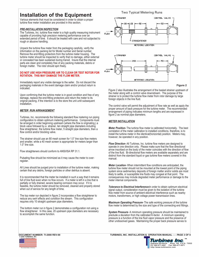
Figure 2 also illustrates the arrangement of the basket strainer upstream of the meter along with a control valve downstream. The purpose of the strainer is to protect the turbine flow meter from rotor damage by large foreign objects in the line fluid.
The control valve will permit the adjustment of flow rate as well as apply the proper amount of back pressure for the turbine meter. The recommended arrangement of piping indicates minimum lengths and are expressed in figure 2 as nominal pipe diameters.
METER INSTALLATION
Meter Position- The turbine flow meter is calibrated horizontally. The best correlation of the meter calibration to installed conditions, therefore, is to install the turbine meter in the identical(horizontal) position. Meters may, however, be operated in any position.
Flow Direction- All Turbines, Inc. turbine flow meters are designed to operate in one direction only. Please make sure that the flow directional arrow inscribed on the body of the meter coincides with the direction of flow of the line fluid. Bi-directional flow meters are available separately and are distinct from the standard liquid or gas turbine flow meters covered in this manual.
Meter Location- When intermittent flow conditions are anticipated, the turbine flow meter should not be mounted at the lowest point of the piping system since sedimentary deposits of foreign matter and/or solids are most likely to settle, or susceptible line fluids may congeal at that point. The consequences may include degraded meter performance or damage to the meter internal components.
Tolerance to Electrical Interference-In order to obtain optimum electrical signal output, consideration must be given to the isolation of the turbine flow meter from source of ambient electrical interference such as nearby motors, transformers, or high voltage power transmission lines.
Maximum Operating Pressure- The safe working pressure of the turbine flow meter is determined by the size and type of the connecting end fittings.
System Pressure- A minimum operating pressure should be maintained to preclude a deviation from the calibrated K-factor. A minimum operating pressure is a function of the line fluid vapor pressure and the presence of other undissolved gases. Maintaining the proper back pressure serves to
Various elements that must be considered in order to obtain a proper turbine flow meter installation are provided in this section.
PRE-INSTALLATION INSPECTIONThe Turbines, Inc. turbine flow meter is a high quality measuring instrument capable of providing high precision metering performance over an extended period of time. It should be treated with care and not subjected to rough or abusive handling.
Unpack the turbine flow meter from the packaging carefully, verify the information on the packing list for Model number and Serial number. Remove the end-fitting protectors from the turbine meter housing. The turbine meter should be inspected to verify that no damage, either external or concealed has been sustained during transit. Insure that the internal parts are clean and completely free of any packing materials, debris or foreign matter. The rotor should spin freely.
Immediately report any visible damage to the seller. Do not discard the packaging materials in the event damage claim and/or product return is indicated.
Upon confirming that the turbine meter is in good condition and free of any damage, replace the end-fitting protectors and return the meter to its original packing, if the intention is to the store the unit until subsequent installation.
METER RUN ARRANGEMENT
Turbines, Inc. recommends the following standard flow metering run piping configuration to obtain optimum metering performance. Components must be arranged in order beginning upstream (where the flow is originating,) a block valve followed by a strainer, ten straight pipe diameters including flow straightener, the turbine flow meter, 5 straight pipe diameters, then a flow control and/or blocking valve.
The strainer should use an 80 mesh screen for 1.0” line size flow meters and smaller, while a 40 mesh screen is appropriate for meters larger than 1.0” line size.
Flow straighteners should conform to ANSI/ISA RP 31.1.
Pulsating flow should be minimized as it may cause the meter to over-register.
All Lines should be purged prior to installation of the turbine meter, making certain that any debris, foreign particles or other detritus is absent.
It is recommended that the meter be installed in such a way that it remains full of line fluid even when no flow occurs. If a meter is left in a line that is partially or fully drained, severe bearing corrosion may occur. If it is feasible, the turbine meter should be removed, cleaned and properly stored when out of service for any length of time.
The top meter run depicted in figure 2 incorporates a flow straightener to reduce any swirl effects and condition the stream. This configuration requires only 10 straight upstream pipe diameters.
The bottom meter run in figure 2 demonstrates a configuration not using a flow straightener. In this case, 20 upstream pipe diameters are necessary to accomplish the same function.
DO NOT USE HIGH PRESSURE AIR TO CLEAN OR TEST ROTOR FOR ROTATION. THIS MAY DAMAGE THE FLOW METER.
Installation of the Equipment
TURBINES, INC. INSTALLATION & OPERATION MANUAL - - - PAGE 3 OF 8DOCUMENT NUMBER: TI-2000 REV-00
Two Typical Metering Runs
Figure 2

TIITurbines Inc.Turbines Inc. ™Highway 283 North Altus, OK U.S.A. 73522 Ph: 580-477-3067 Fax: 580-477-3071 http://www.turbinesinc.com
ELECTRICAL CONNECTIONS
Turbines, Inc. pick-up coils are designed to mate with a two pin MS3106A-10SL-4S connector, for liquid turbine flow meters and a three pin MS3106-10SL-3S connector for gas turbine flow meters. A two or three wire (respectively) shielded cable should be used to lead from the connector to the electronic instrument. The cable shield is connected to the ground contained inside the electronic instrument to prevent any ground-loop interference.
The connection should be located away from power lines whenever possible.
Precautions should be adequate when installing or removing the pick-up coil from the turbine flow meter. Turbines, Inc. warranty does not cover physical damage to the coil.
Proper performance of the equipment is dependent upon correct installation and proper operating procedures being in effect. If the foregoing has been properly executed, then the installation should be good. While not complex, the operating procedure(s) described below are most necessary and must be carefully observed.
OVER RANGE
The greatest hazard to any turbine flow meter is OVER RANGING of the meter. This means that if the flow rate present in the meter is greater than the flow range for which the meter is rated, the meter is said to be “over ranged.”
In case this happens, the performance of the turbine meter will, generally, remain linear, however, the pressure drop (head loss) will increase and the radial velocity of the rotor will exceed its design limits, quite likely resulting in permanent damage due to overspeeding of the bearings.
In liquid applications, over speed usually occurs during startup when air is present in the metering line. Air should be bled from meter line prior to a startup operation.
UNDER RANGE
As suggested by the nomenclature, under ranging is defined as operating the turbine flow meter below the flow rate minimum for which the meter is rated. While this will not cause physical damage to the equipment, operating beneath the minimum rated range limit of a turbine flow meter will cause the accuracy to become non-linear and the repeatability will become poor due to increased proportional effect of the bearing friction.
LIQUID FLOW CHARACTERISTICS
When measuring liquids, a turbine flow meter output is related to an absolute standard because the volume of the liquid is considered to be incompressible.
Each turbine flow meter has its own unique k-factor, as derived by calibration wherein a known volume of liquid is passed through the meter in a known span of time.
The turbine meter’s linearity is expressed as the variation in the k-factor over its flow range. The k-factor changes slightly over the flow range of the turbine meter, therefore the linearity is the change(deviation) of the actual k-factor from the nominal k-factor.
If the application line fluid differs from water (the calibration medium,) the k-factor provided with the turbine flow meter may not accurately reflect the
METER INSTALLATION(continued)
System Pressure(continued)-prevent cavitation and fluid separation.
Calculation of the required back pressure for liquid line fluid applications is calculated as follows:
BP = (meter P x 2) + (VP x 1.25) where BP = Back pressure,P = Flow meter pressure drop at maximum flow,andVP = Line fluid Vapor Pressure at maximum temperature(psig)
PICK-UP COIL INSTALLATION
Pick-up coils should be inserted into the threaded hub of the turbine flow meter, with the electronic connector end of the pick-up coil facing out. This component should be finger tightened to approximately 4in-lb torque.
The magnetic pick-up coil produces a low level sine wave output that requires an amplifier to convert the signal to 0 to 10 volt peak to peak pulse signal suitable for process instrumentation.
The modulated carrier (RF) pick-up has the required amplifier built into the pick-up. This also produces a 0 to 10 volt peak to peak pulse.
The following must be observed to obtain proper operating performance:
Use a twisted and shielded cable (Belden 8761 or equivalent) to carry the signal.
The shield should only be connected at one end! This will prevent a ground loop.
Do not mount the meter/pick-up close to electrical noise generating equipment (motors, relays, etc.)
The conduit for the pick-up cable must not be shared with other service(s).
GENERAL PIPING CONSIDERATIONS
As explained in earlier section(s), the line fluid moving through the flow meter causes the rotor to rotate. Thus the rotational velocity of the rotor is a function of the line fluid velocity and the blade angle engagement. Swirl present in the line fluid stream can effectively change the angle of engagement between the fluid stream and the rotor blades and therefore result in a deviation from the calibrated k-factor supplied with the turbine meter (since the calibration is performed under controlled flow conditions.)Proper installation as described elsewhere herein, minimizes the harmful effects of fluid swirl.
Meter By-Pass - Where possible, it is advisable to include a valved by-pass around the “ metering location”. This foresight will allow the turbine flow meter to be removed without interrupting the operation of the line.
Line Purge - In a new or revised piping system, the line should be flushed prior to the installation of the turbine flow meter to minimize damage from foreign materials otherwise present in the line.
Air-Bleed- In liquid turbine applications, air (any gas) should be bled from the liquid line fluid prior to start up.
PAGE 4 OF 8 - - - TURBINES, INC. INSTALLATION & OPERATION MANUAL
DOCUMENT NUMBER: TI-2000 REV-00
Operation of the Equipment
TIITurbines Inc.Turbines Inc. ™PROUDLY MANUFACTURED IN
The United States of America
© 2000 TURBINES, INC.
Highway 283 North Altus, OK U.S.A. 73522 Ph: 580-477-3067 Fax: 580-477-3071 http://www.turbinesinc.com
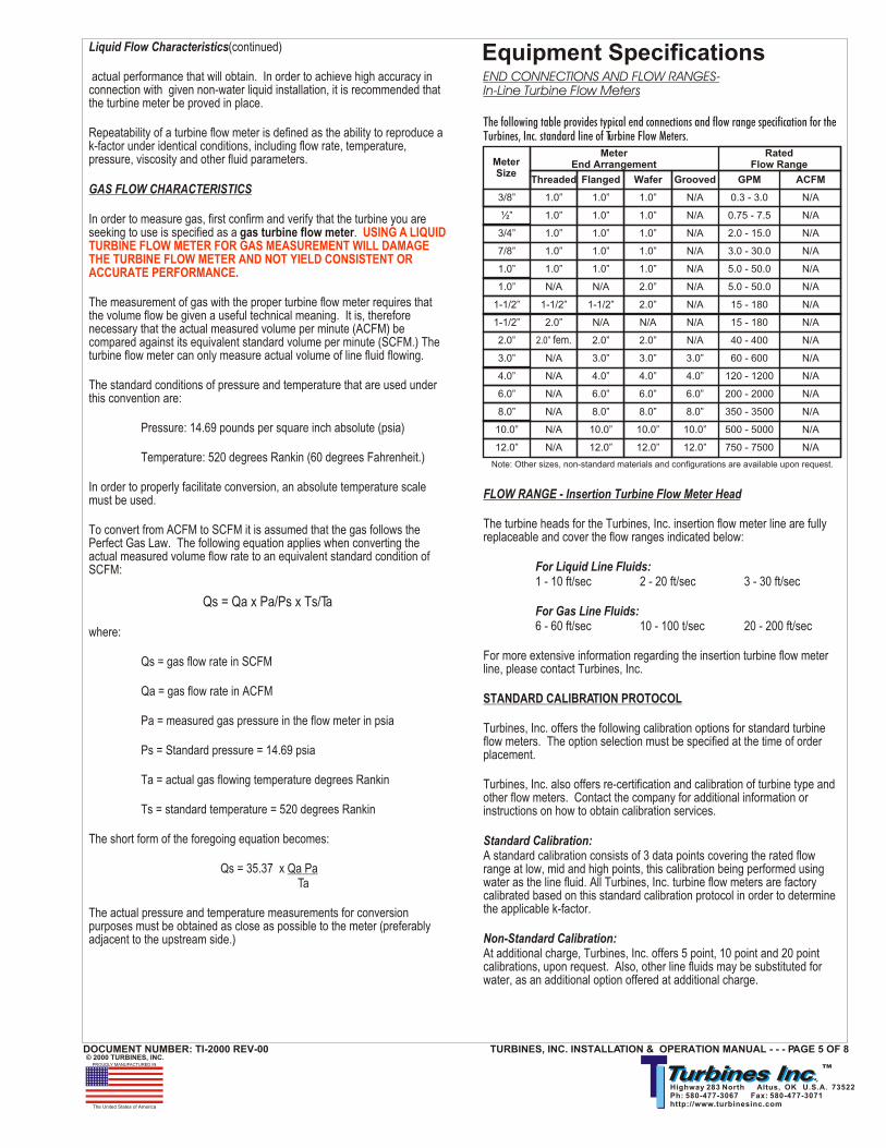
END CONNECTIONS AND FLOW RANGES-In-Line Turbine Flow Meters
The following table provides typical end connections and flow range specification for the Turbines, Inc. standard line of Turbine Flow Meters.
FLOW RANGE - Insertion Turbine Flow Meter Head
The turbine heads for the Turbines, Inc. insertion flow meter line are fully replaceable and cover the flow ranges indicated below:
For Liquid Line Fluids:1 - 10 ft/sec 2 - 20 ft/sec 3 - 30 ft/sec
For Gas Line Fluids:6 - 60 ft/sec 10 - 100 t/sec 20 - 200 ft/sec
For more extensive information regarding the insertion turbine flow meter line, please contact Turbines, Inc.
STANDARD CALIBRATION PROTOCOL
Turbines, Inc. offers the following calibration options for standard turbine flow meters. The option selection must be specified at the time of order placement.
Turbines, Inc. also offers re-certification and calibration of turbine type and other flow meters. Contact the company for additional information or instructions on how to obtain calibration services.
Standard Calibration:A standard calibration consists of 3 data points covering the rated flow range at low, mid and high points, this calibration being performed using water as the line fluid. All Turbines, Inc. turbine flow meters are factory calibrated based on this standard calibration protocol in order to determine the applicable k-factor.
Non-Standard Calibration:At additional charge, Turbines, Inc. offers 5 point, 10 point and 20 point calibrations, upon request. Also, other line fluids may be substituted for water, as an additional option offered at additional charge.
Liquid Flow Characteristics(continued)
actual performance that will obtain. In order to achieve high accuracy in connection with given non-water liquid installation, it is recommended that the turbine meter be proved in place.
Repeatability of a turbine flow meter is defined as the ability to reproduce a k-factor under identical conditions, including flow rate, temperature, pressure, viscosity and other fluid parameters.
GAS FLOW CHARACTERISTICS
In order to measure gas, first confirm and verify that the turbine you are seeking to use is specified as a gas turbine flow meter.
The measurement of gas with the proper turbine flow meter requires that the volume flow be given a useful technical meaning. It is, therefore necessary that the actual measured volume per minute (ACFM) be compared against its equivalent standard volume per minute (SCFM.) The turbine flow meter can only measure actual volume of line fluid flowing.
The standard conditions of pressure and temperature that are used under this convention are:
Pressure: 14.69 pounds per square inch absolute (psia)
Temperature: 520 degrees Rankin (60 degrees Fahrenheit.)
In order to properly facilitate conversion, an absolute temperature scale must be used.
To convert from ACFM to SCFM it is assumed that the gas follows the Perfect Gas Law. The following equation applies when converting the actual measured volume flow rate to an equivalent standard condition of SCFM:
Qs = Qa x Pa/Ps x Ts/Ta
where:
Qs = gas flow rate in SCFM
Qa = gas flow rate in ACFM
Pa = measured gas pressure in the flow meter in psia
Ps = Standard pressure = 14.69 psia
Ta = actual gas flowing temperature degrees Rankin
Ts = standard temperature = 520 degrees Rankin
The short form of the foregoing equation becomes:
Qs = 35.37 x Qa Pa Ta
The actual pressure and temperature measurements for conversion purposes must be obtained as close as possible to the meter (preferably adjacent to the upstream side.)
USING A LIQUID TURBINE FLOW METER FOR GAS MEASUREMENT WILL DAMAGE THE TURBINE FLOW METER AND NOT YIELD CONSISTENT OR ACCURATE PERFORMANCE.
TURBINES, INC. INSTALLATION & OPERATION MANUAL - - - PAGE 5 OF 8DOCUMENT NUMBER: TI-2000 REV-00
Equipment Specifications
Meter Size
Meter End Arrangement
Rated Flow Range
3/8”
½”
3/4”
7/8”
1.0”
1.0”
1-1/2”
1-1/2”
2.0”
3.0”
4.0”
6.0”
8.0”
10.0”
12.0”
Note: Other sizes, non-standard materials and configurations are available upon request.
1.0”
1.0”
1.0”
1.0”
1.0”
N/A
1-1/2”
2.0”
2.0” fem.
N/A
N/A
N/A
N/A
N/A
N/A
Threaded Flanged Wafer Grooved GPM ACFM
1.0”
1.0”
1.0”
1.0”
1.0”
N/A
1-1/2”
N/A
2.0”
3.0”
4.0”
6.0”
8.0”
10.0”
12.0”
1.0”
1.0”
1.0”
1.0”
1.0”
2.0”
2.0”
N/A
2.0”
3.0”
4.0”
6.0”
8.0”
10.0”
12.0”
N/A
N/A
N/A
N/A
N/A
N/A
N/A
N/A
N/A
3.0”
4.0”
6.0”
8.0”
10.0”
12.0”
0.3 - 3.0
0.75 - 7.5
2.0 - 15.0
3.0 - 30.0
5.0 - 50.0
5.0 - 50.0
15 - 180
15 - 180
40 - 400
60 - 600
120 - 1200
200 - 2000
350 - 3500
500 - 5000
750 - 7500
N/A
N/A
N/A
N/A
N/A
N/A
N/A
N/A
N/A
N/A
N/A
N/A
N/A
N/A
N/A
TIITurbines Inc.Turbines Inc. ™PROUDLY MANUFACTURED IN
The United States of America
© 2000 TURBINES, INC.
Highway 283 North Altus, OK U.S.A. 73522 Ph: 580-477-3067 Fax: 580-477-3071 http://www.turbinesinc.com
TEMPERATURE(continued)Unless a high temperature pick-up coil is selected and secondary electronics are remotely mounted, temperatures exceeding the rated maximum may cause irreparable damage.
Lower temperatures will limit the rotation of the rotor and cause the electronic display(s) to cease functioning until acceptable temperature is restored.
PRESSURE
Never exceed the pressure rating of the turbine meter. Excessive pressure may cause inaccurate registration of the turbine flow meter, or may result in the rupture or explosion of the flow element.
When pressurizing an empty line, gradually increase pressure incrementally until full required line pressure that is compliant with rated pressure of the flow element(s) is achieved. Do not quickly approach full pressurization.
Damage to the turbine flow meter consistent with failure to comply with the foregoing shall immediately void any warranty otherwise operative.
CORROSION
The standard design for Turbines, Inc. turbine flow meters consists of stainless steel and tungsten carbide internals. It is essential that the user confirms that these materials are compatible with the process line fluid. Incompatible process line fluids may cause premature deterioration of meter components, and lead to inaccurate meter registration and eventual failure.
If the compatibility of an intended process line fluid is questioned, contact the factory for application assistance. Alternate and/or non-standard materials selection can be facilitated resulting in the production of flow elements that will be fully compatible.
PULSATING FLOW ISSUES
Severe pulsation of flow will affect the accuracy of the turbine flow meter, and shorten the useful service life of the equipment.
VIBRATION AND SHOCK
Severe mechanical shock and/or vibration may decrease the useful service life of the meter. Excessive mechanical shock and/or vibration may cause structural failure of connections between meter and secondary (monitor/totalizer.
CONTROL OR THROTTLING VALVE(S)
Throttling valves should be installed downstream of the turbine flow meter only.
FILTRATION
A strainer should be installed upstream of the turbine flow meter. Suspended particles and/or foreign matter may damage rotor and/or other internal components.
LINE FLUID-FLOW CONDITIONS
Never introduce air or gaseous substances or flow into a liquid turbine flow meter. Liquid and Gas turbine flow meters are not interchangeable!
WARNING: DO NOT REMOVE METER FROM A PRESSURIZED LINE.
MATERIALS OF CONSTRUCTION
Turbines, Inc. offers the standard turbine flow meter product line with material configuration as follows:
Meter Body: 316 stainless steelBearing Support: 316 stainless steelRotor: 416 stainless steelShaft & Bearing (Liquid): tungsten carbideShaft & Bearing (Gas): 316 stainless steel shaft 440C stainless steel Ball Bearings
Other materials such as Hastelloy, Monel, various plastics and so forth, are available by special request.
PICK-UP COILSThe following pick-up coils are available:
Magnetic pick-up coil to +225 deg. F.Magnetic pick-up coil to +450 deg. F.Magnetic pick-upcoil to +850 deg. F.
Modulated carrier (RF) with preamplifierMagnetic pick-up coil with preamplifier
FLOW MONITORS-TOTALIZERS
Turbines, Inc. offers several proprietary monitor/totalizer units as well as a number of OEM units. Operation and Maintenance of these pieces of equipment are separately provided.
Generally, however, monitor/totalizers offer Nema 4X enclosures with LED read-out calibrated to units of measure suitable to the user’s application. Such units can be configured to either direct mount onto the hub of the turbine flow meter, or alternatively, to be remote mounted using additional cable set. As well, local indication can be augmented by the addition of 4 - 20 mA output features.
These units can be of explosion proof and intrinsically safe design, as well as certified to various industry standards, depending upon application requirements.
Gas turbine flow measurement requires monitor/totalizer equipment capable of integrating line pressure and temperature data in order to compensate for the compressibility of gases.
Depending upon application specifications, monitor/totalizer equipment can be expanded to handle batching, control, reporting and other functions. Consult factory for further information and applications support.
INSTALLATION
The flow directional arrow prominently displayed on the body of the turbine flow meter must coincide with the direction of flow of the process line fluid.
TEMPERATURE
Do not subject the meter electronics (i. e. monitors/totalizers, etc.) to temperatures in excess of 160 degrees F.
Do not subject the meter (or electronics) to temperatures below the freezing point of the process line fluid.
PAGE 6 OF 8 - - - TURBINES, INC. INSTALLATION & OPERATION MANUAL DOCUMENT NUMBER: TI-2000 REV-00
Operating Limitations Notes

TIITurbines Inc.Turbines Inc. ™PROUDLY MANUFACTURED IN
The United States of America
© 2000 TURBINES, INC.
Highway 283 North Altus, OK U.S.A. 73522 Ph: 580-477-3067 Fax: 580-477-3071 http://www.turbinesinc.com
STANDARD IN-LINE THREADED, FLANGED OR GROOVED TURBINE FLOW METER(continued)
Step 2Make sure that all power to any connected secondary device(s) has been disconnected. Remove any connections to the pick-up coil.
Step 3Remove retaining rings from both ends of the meter body.
Step 4Remove forward rotor support assembly, rotor, and rear rotor support assembly carefully.
Step 5Thoroughly inspect all internal components for evidence of wear, degradation, corrosion, foreign debris entanglement, and physical damage. Nicks, dents, misalignment of blades, or encrustation on the rotor assembly can cause the turbine flow meter to register incorrectly.
Step 6Any component parts constituting the internals that demonstrate evidence described in #5 above should be replaced with authorized replacement components available by calling the factory.
Step 7Clean all parts thoroughly and immerse in light machine oil prior to reassembly.
Re-assembly
Step 1Internal components must be reassembled exactly as they were previously removed.
Step 2Insert rear rotor support making sure to firmly seat this part in grooves provided to prevent rotor support from turning.
Step 3Insert rotor, then front rotor support.
Step 4Install retaining rings in machined body groove. Make sure they seat firmly into the groove.
Step 5Verify that the rotor support(s) do not rotate within the body housing.
Step 6Examine and verify that the rotor assembly spins freely without any disruption, bias or binding.
STANDARD WAFER STYLE TURBINE FLOW METER
Disassembly
Step 1Prior to removing any flow element from the process line, MAKE SURE THAT ALL PRESSURE HAS BEEN RELIEVED FROM THE LINE, and that no line fluid is flowing.
Step 2Make sure that all power to any connected secondary device(s) has been disconnected. Remove any connections to the pick-up coil.
Consult Figure 3a following for detailed typical drawing.
LINE FLUID-FLOW CONDITIONS(continued)
The turbine flow meter should be operated within the specified rated range of the meter. Don not run below the minimum limit of the flow range as it will result in inaccuracies.
Do not exceed the maximum imit of the flow range as this may damage the turbine flow meter.
By observing proper maintenance procedures the useful service life of the turbine flow meter can be prolonged and with the exception of replaceable parts, the meter can be expected to perform for an extended period of time.
PERIODIC MAINTENANCE
Maintenance for Turbines, Inc. turbine flow meters consists of periodic inspection of the internal components, namely rotor supports, rotor and bearings. Excessive wear, physical damage, or clogging must be identified promptly. Should evidence of such conditions be present, it is recommended that the meter be returned to the factory to be rebuilt.
Complete sets of calibrated internal retro-fit kits are available in the event field retro-fitting and/or replacement is desired. Consult with factory for assistance.
INSPECTION AND CLEANING
In order to inspect or clean the turbine flow meter, the retaining ring must be removed. At that point, the rotor support and rotor can be removed.
Particularly if the meter has been out of service for a period of time, it is recommended that it be dipped in light machine oil.
One of the primary sources of turbine meter failure is the bearing wear caused by foreign material build-up. A large number of process line fluids will leave residue that severely degrades the free motion of the rotor.
It is recommended that the meter be flushed with Stoddard solvent whenever possible.
If the bearings become worn or damaged, contact the factory for retro-fit internals kit. Otherwise, return meter for factory re-build.
In order to perform regular maintenance and occasional field retro-fit the need will arise to disassemble and assemble the turbine flow meter. The pertinent procedures for standard Turbines, Inc. turbine flow meters are offered in the following sections.
Each type of turbine flow meter is listed with the appropriate procedure steps listed. There follows a series of illustrations in figure 3 that relate to these procedures, and provide general typical drawings for the various meter styles. Additional assistance, if required, may be obtained by contacting the factory.
STANDARD IN-LINE THREADED, FLANGED OR GROOVED TURBINE FLOW METER
Disassembly
Step 1Prior to removing any flow element from the process line, MAKE SURE THAT ALL PRESSURE HAS BEEN RELIEVED FROM THE LINE, and that no line fluid is flowing.
TURBINES, INC. INSTALLATION & OPERATION MANUAL - - - PAGE 7 OF 8DOCUMENT NUMBER: TI-2000 REV-00
Equipment Maintenance
Disassembly and Assembly Notes
TIITurbines Inc.Turbines Inc. ™PROUDLY MANUFACTURED IN
The United States of America
© 2000 TURBINES, INC.
Highway 283 North Altus, OK U.S.A. 73522 Ph: 580-477-3067 Fax: 580-477-3071 http://www.turbinesinc.com
STANDARD WAFER STYLE TURBINE FLOW METERDisassembly (continued)
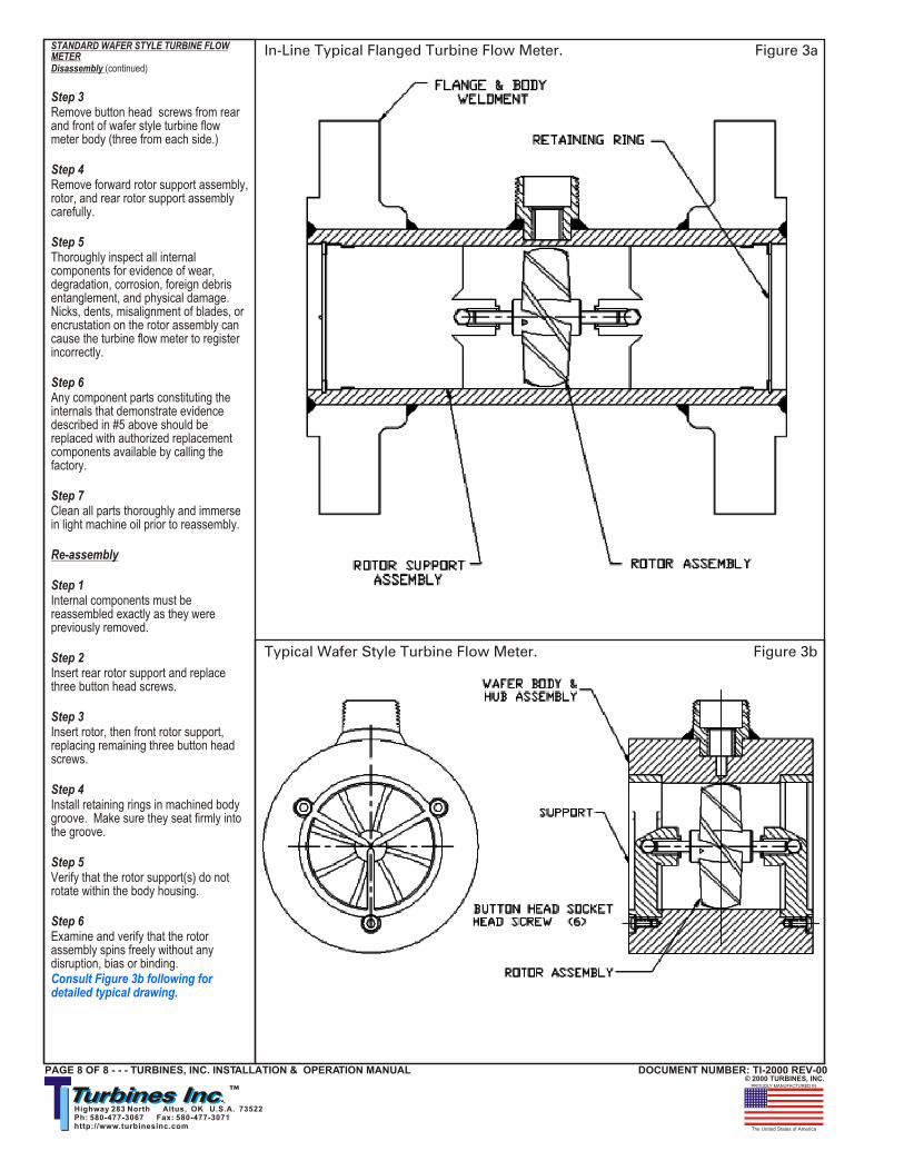
Step 3Remove button head screws from rear and front of wafer style turbine flow meter body (three from each side.)
Step 4Remove forward rotor support assembly, rotor, and rear rotor support assembly carefully.
Step 5Thoroughly inspect all internal components for evidence of wear, degradation, corrosion, foreign debris entanglement, and physical damage. Nicks, dents, misalignment of blades, or encrustation on the rotor assembly can cause the turbine flow meter to register incorrectly.
Step 6Any component parts constituting the internals that demonstrate evidence described in #5 above should be replaced with authorized replacement components available by calling the factory.
Step 7Clean all parts thoroughly and immerse in light machine oil prior to reassembly.
Re-assembly
Step 1Internal components must be reassembled exactly as they were previously removed.
Step 2Insert rear rotor support and replace three button head screws.
Step 3Insert rotor, then front rotor support, replacing remaining three button head screws.
Step 4Install retaining rings in machined body groove. Make sure they seat firmly into the groove.
Step 5Verify that the rotor support(s) do not rotate within the body housing.
Step 6Examine and verify that the rotor assembly spins freely without any disruption, bias or binding.Consult Figure 3b following for detailed typical drawing.
PAGE 8 OF 8 - - - TURBINES, INC. INSTALLATION & OPERATION MANUAL DOCUMENT NUMBER: TI-2000 REV-00
Figure 3b
Figure 3aIn-Line Typical Flanged Turbine Flow Meter.
Typical Wafer Style Turbine Flow Meter.