installation & operation manual - gorbel
TRANSCRIPT

IMPORTANT!DO NOT DESTROY
Installation &Operation Manual
Month Year
Gorbel® Dealer
Date
G-Force®Q and iQ Series
Gorbel® Customer Order No. / Serial No.
®
Go to www.gorbel.com/support/warrantyregistration.aspx to register your G-Force®, sign up for our PlatinumService Package and request your free G-Force® Q and iQ Series Service Manual.

This page intentionally left blank.

TABLE OF CONTENTSSafe Hoist Operating Guidelines ......................................................................................... 1-3
Introduction .............................................................................................................................4
Correct G-Force® Installation Orientation ..............................................................................5
G-Force® Main Assembly Component Description ...............................................................6
Installation Step 1 - Unpacking the G-Force® ..................................................................................................... 7 Step 2 - Pre-Assembly / Tools Required ........................................................................................... 7 Step 3 - Actuator Assembly Installation ............................................................................................ 7 Step 4 - Coil Cord Installation ........................................................................................................... 8 Step 5A - In-Line Slide & Force Sensing Slide Handle Installation ..................................................... 9 Step 5B - Remote Mounted Slide Handle Installation .................................................................... 9-10 Step 5C - Suspended Pendant Handle Installation ........................................................................... 11 Step 5D - Remote Mounted Pendant Handle Installation ............................................................. 11-12 Step 5E - 1320 Lb. In-Line Slide or Remote Mounted Handle Installation ....................................... 13 Step 5F - 1320 Lb. Suspended Pendant Handle Installation ............................................................ 14 Step 5G - 1320 Lb. Air Hose Installation (Option) ............................................................................. 14 Step 5H - Remote Mount Force Sensing Slide Handle Installation ................................................... 15 Step 5I - Remote Mount Force Sensing Hub Handle Installation .................................................... 16 Step 6 - Electrical Power Connection.............................................................................................. 17 Step 7 - Initial Power-Up ................................................................................................................. 17 Step 8 - Float Mode and Final Steps ......................................................................................... 18-19 Step 9 - Expansion I/O Block Mounting Instructions (Option) ......................................................... 20
Lift Functionality ...............................................................................................................21-23
Controls Interface Features .................................................................................................. 24
Program Mode
Overview & Basic Features ............................................................................................................ 25-29 Custom Feature Definition and Requirements ............................................................................... 30-35 Input/Output Points ......................................................................................................................... 36-41
Troubleshooting
Basic Troubleshooting ......................................................................................................................... 42 System Fault Diagnostics Chart .......................................................................................................... 43 Diagnostic Mode Test Chart ................................................................................................................ 44
Technical Specifications .......................................................................................................45
Wire Rope Inspection, Maintenance, & Replacement .....................................................46-50
Slack Spring Adjustment ...................................................................................................... 51
Recommended Spare Parts Kits .......................................................................................... 52
Limited Warranty ..................................................................................................................53
Inspection and Maintenance Schedule ................................................................................ 56
Questions? Concerns? Comments? Please call (800) 821-0086 (US and Canada) or (585) 924-6262 (outside US).

This page intentionally left blank.
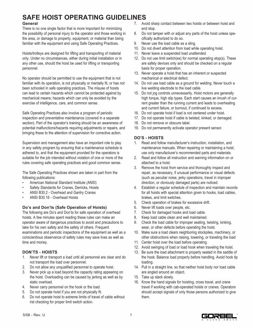
SAFE HOIST OPERATING GUIDELINESGeneralThere is no one single factor that is more important for minimizing the possibility of personal injury to the operator and those working in the area, or damage to property, equipment, or material than being familiar with the equipment and using Safe Operating Practices.
Hoists/trolleys are designed for lifting and transporting of material only. Under no circumstances, either during initial installation or in any other use, should the hoist be used for lifting or transportingpersonnel.
No operator should be permitted to use the equipment that is not familiar with its operation, is not physically or mentally fit, or has not been schooled in safe operating practices. The misuse of hoists can lead to certain hazards which cannot be protected against by mechanical means; hazards which can only be avoided by theexercise of intelligence, care, and common sense.
Safe Operating Practices also involve a program of periodicinspection and preventative maintenance (covered in a separate section). Part of the operator’s training should be an awareness of potential malfunctions/hazards requiring adjustments or repairs, and bringing these to the attention of supervision for corrective action.
Supervision and management also have an important role to play in any safety program by ensuring that a maintenance schedule is adhered to, and that the equipment provided for the operators is suitable for the job intended without violation of one or more of the rules covering safe operating practices and good common sense.
The Safe Operating Practices shown are taken in part from thefollowing publications:• American National Standard Institute (ANSI)• Safety Standards for Cranes, Derricks, Hoists• ANSI B30.2 - Overhead and Gantry Cranes• ANSI B30.16 - Overhead Hoists
Do’s and Don’ts (Safe Operation of Hoists)The following are Do’s and Don’ts for safe operation of overhead hoists. A few minutes spent reading these rules can make anoperator aware of dangerous practices to avoid and precautions to take for his own safety and the safety of others. Frequentexaminations and periodic inspections of the equipment as well as a conscientious observance of safety rules may save lives as well as time and money.
DON’TS - HOISTS1. Never lift or transport a load until all personnel are clear and do
not transport the load over personnel.2. Do not allow any unqualified personnel to operate hoist.3. Never pick up a load beyond the capacity rating appearing on
the hoist. Overloading can be caused by jerking as well as by static overload.
4. Never carry personnel on the hook or the load.5. Do not operate hoist if you are not physically fit.6. Do not operate hoist to extreme limits of travel of cable without
irst checking for proper limit switch action.
7. Avoid sharp contact between two hoists or between hoist and end stop.
8. Do not tamper with or adjust any parts of the hoist unless spe-cifically authorized to do so.
9. Never use the load cable as a sling.10. Do not divert attention from load while operating hoist.11. Never leave a suspended load unattended.12. Do not use limit switch(es) for normal operating stop(s). These
are safety devices only and should be checked on a regular basis for proper operation.
13. Never operate a hoist that has an inherent or suspected mechanical or electrical defect.
14. Do not use load cable as a ground for welding. Never touch a live welding electrode to the load cable.
15. Do not jog controls unnecessarily. Hoist motors are generally high torque, high slip types. Each start causes an inrush of cur-rent greater than the running current and leads to overheating and current failure, or burnout, if continued to excess.
16. Do not operate hoist if load is not centered under hoist.17. Do not operate hoist if cable is twisted, kinked, or damaged.18. Do not remove or obscure label.19. Do not permanently activate operator present sensor.
DO’S - HOISTS1. Read and follow manufacturer’s instruction, installation, and
maintenance manuals. When repairing or maintaining a hoist, use only manufacturer’s recommended parts and materials.
2. Read and follow all instruction and warning information on or attached to a hoist.
3. Remove the hoist from service and thoroughly inspect and repair, as necessary, if unusual performance or visual defects (such as peculiar noise, jerky operations, travel in improper direction, or obviously damaged parts) are noticed.
4. Establish a regular schedule of inspection and maintain records for all hoists with special attention given to hooks, load cables, brakes, and limit switches.
5. Check operation of brakes for excessive drift.6. Never lift loads over people, etc.7. Check for damaged hooks and load cable.8. Keep load cable clean and well maintained.9. Check the load cable for improper seating, twisting, kinking,
wear, or other defects before operating the hoist.10. Make sure a load clears neighboring stockpiles, machinery, or
other obstructions when raising, lowering, or traveling the load11. Center hoist over the load before operating.12. Avoid swinging of load or load hook when traveling the hoist.13. Be sure the load attachment is properly seated in the saddle of
the hook. Balance load properly before handling. Avoid hook tip loading.
14. Pull in a straight line, so that neither hoist body nor load cable are angled around an object.
15. Take up slack slowly.16. Know the hand signals for hoisting, cross travel, and crane
travel if working with cab-operated hoists or cranes. Operators should accept signals of only those persons authorized to give them.
15/08 - Rev. U
2 5/08 - Rev. U
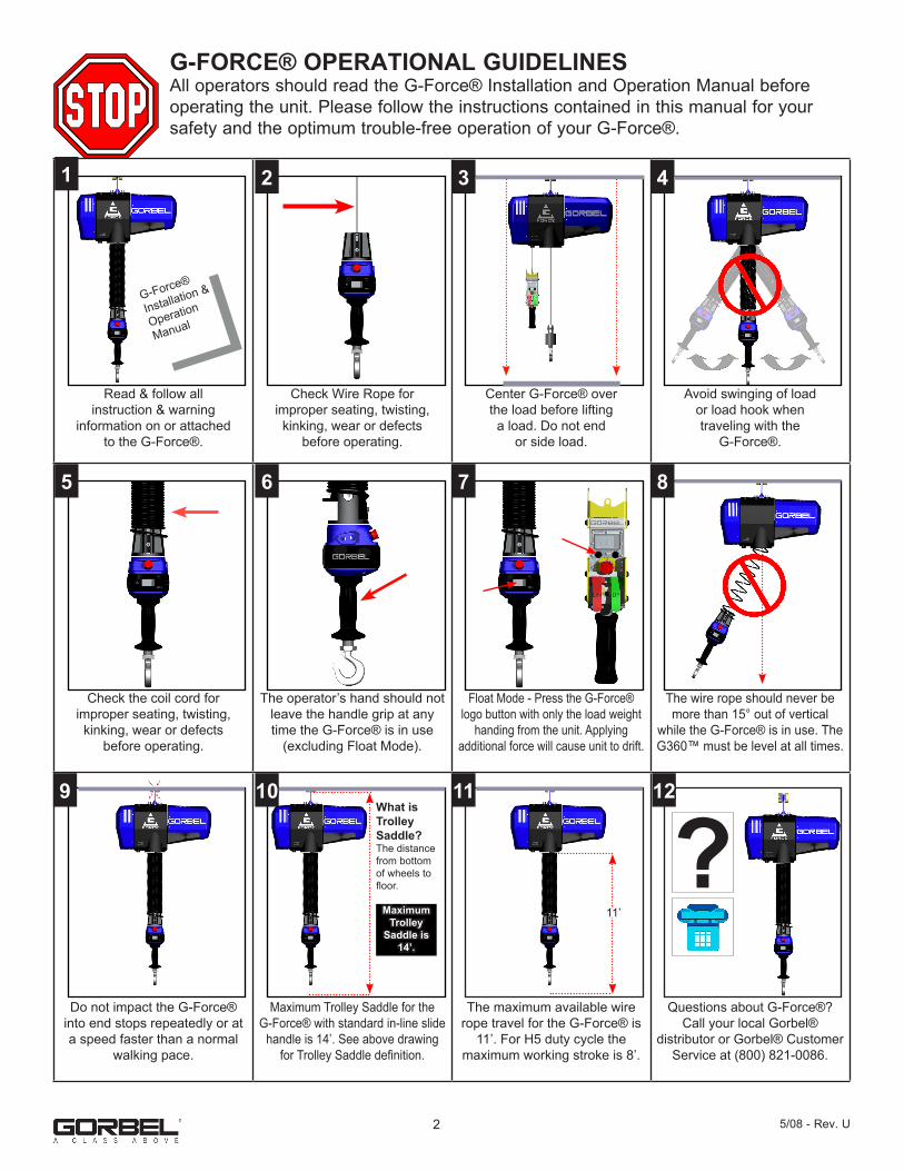
G-FORCE® OPERATIONAL GUIDELINESAll operators should read the G-Force® Installation and Operation Manual before operating the unit. Please follow the instructions contained in this manual for your safety and the optimum trouble-free operation of your G-Force®.
Read & follow allinstruction & warning
information on or attachedto the G-Force®.
Check Wire Rope forimproper seating, twisting,kinking, wear or defects
before operating.
Center G-Force® overthe load before liftinga load. Do not end
or side load.
Avoid swinging of loador load hook whentraveling with the
G-Force®.
Check the coil cord forimproper seating, twisting,kinking, wear or defects
before operating.
The operator’s hand should not leave the handle grip at any time the G-Force® is in use
(excluding Float Mode).
Float Mode - Press the G-Force® logo button with only the load weight
handing from the unit. Applyingadditional force will cause unit to drift.
The wire rope should never be more than 15° out of vertical
while the G-Force® is in use. The G360™ must be level at all times.
Do not impact the G-Force® into end stops repeatedly or at a speed faster than a normal
walking pace.
Maximum Trolley Saddle for theG-Force® with standard in-line slide
handle is 14’. See above drawing for Trolley Saddle definition.
The maximum available wire rope travel for the G-Force® is
11’. For H5 duty cycle themaximum working stroke is 8’.
Questions about G-Force®? Call your local Gorbel®
distributor or Gorbel® Customer Service at (800) 821-0086.
G-Force®
Installation &
Operation
Manual
1
9 10 11 12
8765
432
What is Trolley Saddle?The distance from bottom of wheels to floor.
Maximum Trolley
Saddle is 14’.
11’
?

WARNINGS
TOOLING INTEGRATION GUIDELINES
IMPORTANT SAFETY INSTRUCTIONS
1. All operators should read the G-Force® Installation and Operation Manual before operating the unit.2. Check wire rope for improper seating, twisting, kinking, wear, or defects before operating.3. Center the G-Force® over the load before lifting. DO NOT end or side load the G-Force®. End or side loading will seriously reduce the life of the wire rope and lead to premature failure. The wire rope should never exceed an out of vertical angle greater than 15° under any circumstances.4. Avoid swinging of load or load hook when traveling with the G-Force®.5. Check the coil cord for improper seating, twisting, kinking, wear, or defects before operating. Any of the described conditions will seriously reduce the life of the coil cord and lead to premature failure.6. Press the G-Force® logo button for Float Mode (option) with only the load weight hanging from the unit. Additional external forces applied to the load during initiation of Float Mode will result in the load drifting.7. Do not repeatedly impact the G-Force® into the end stops. This condition will seriously reduce the life of the controls and could lead to premature failures. If the unit impacts the end stop more than 10 times in a single shift, contact Gorbel® Inside Sales for alternative end stop options.8. The G-Force® does not meet “wash-down” environment requirements. The G-Force® does not meet “explosion proof” requirements.9. Ensure that the slide handle is supported properly in remote mounted handle applications by mounting the slide handle at both the top and bottom mounting points (diagram D, page 23).10. Do not mount any objects to the G-Force® slide handle grip (i.e. switches). Additional objects may interfere with the travel of the sliding handle grip and affect the overall speed and functionality of the unit.11. Do not mount any load bearing components to the blue housing of the G-Force® slide handle, pendant handle, or actuator assembly.
WARNINGS
1. All tooling must be retained to the G360™ assembly utilizing the M16 thread and locking pin provided. The locking pin is optional on Slide Handle and Wire Rope Swivel assemblies if proper inspection and maintenance procedures are followed.2. Do not mount anything to the G-Force® handle housing. Use supplied brackets, valves, and switches whenever possible.3. In-line tooling must always be centered directly under the hand controller.4. Tooling design which does not keep the tooling level; and balanced in both the loaded and unloaded condition may induce a bending force on the handle and/or collector assembly which may reduce the life and/or performance of the handle and/or collector assembly5. Do not mount anything to the sliding portion of the G-Force® hand controller.6. Do not alter or add conductors to the G-Force® coil cord.7. Use only Gorbel’s slide on air hose (slides over coil cord) to supply air power to end effector tooling. Gorbel cannot guarantee performance or functionality of other methods of supplying air power to end effector tooling.8. All cables used in a remote mounted handle configuration must be properly clamped and/or strain-relieved to prevent premature failure of the G-Force® or customer tooling.,
35/08 - Rev. U

INTRODUCTIONThank you for choosing a Gorbel® G-Force® Intelligent Lifting Device (ILD)** to solve your material han-dling needs. The G-Force® is a servomotor driven, high speed, ergonomic materials handling device. The innovative design and heavy-duty construction of the G-Force® will provide a superior quality product that will offer years of long term value. A Gorbel® G-Force® will provide many years of dependable service by following the installation and maintenance procedures described herein.
** U.S. Patent No’s: 5,865,426, 6,622,990, 6,386,513, & 6,886,812, Other Patents Pending
Dimensions contained in this installation manual are for reference only and may differ for your particular application.
WARNINGOnly competent erection personnel familiar with standard fabrication practices should be employed to install the G-Force® because of the necessity of properly interpreting these instructions. Gorbel is not responsible for the quality of workmanship employed in the installation of this hoist according to these instructions. Contact Gorbel, Inc., at 600 Fishers Run, P.O. Box 593, Fishers, New York 14453, 1-585-924-6262, for additional information if necessary.
WARNINGEquipment described herein is not designed for, and should not be used for, lifting, supporting, or trans-porting humans. Failure to comply with any one of the limitations noted herein can result in serious bodily injury and/or property damage. Check Federal, State and Local regulations for any additional require-ments.
WARNINGPrior to installation, consult a qualified structural engineer to determine if your support structure is ade-quate to support the loadings created during normal operation of the G-Force®.
WARNINGReference American Institute of Steel Construction (AISC) Manual of Steel Construction (9th edition), Part 5, Specification for Structural Joints using ASTM A325 or A490 Bolts (section 8.d.2) for proper procedure to follow when using any torque tightening methods.
WARNINGDo not field modify the G-Force® actuator or handles in any way. Any modification, without the written consent of Gorbel, Inc., will void warranty.
WARNINGThe jog switch buttons are for system maintenance and load testing only, and should not be manipulated during normal operation of the G-Force®. Operation of the jog switch buttons during normal operation increases the risk of personal injury to the operator.
4 5/08 - Rev. U
WARNINGGorbel Inc. authorizes use of wire rope only as supplied by Gorbel for any G-Force® equipment. Use of other than Gorbel supplied wire rope shall void Gorbel’s warranty of the product.
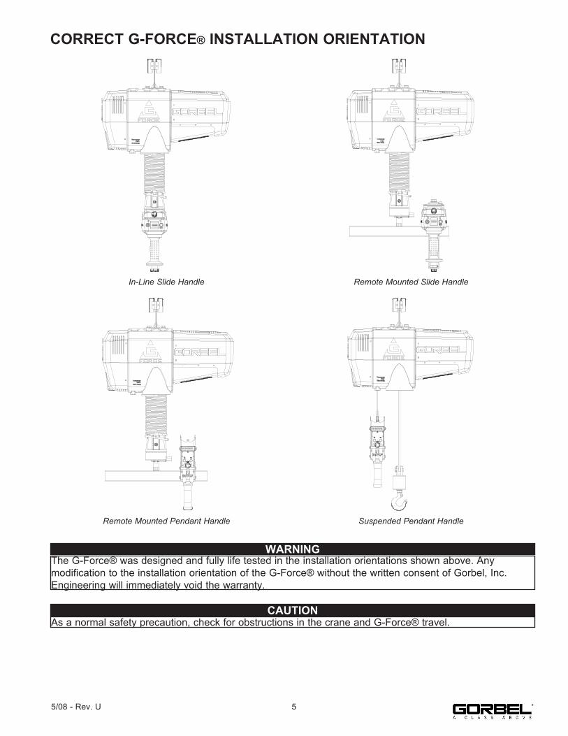
CORRECT G-FORCE® INSTALLATION ORIENTATION
In-Line Slide Handle Remote Mounted Slide Handle
Remote Mounted Pendant Handle Suspended Pendant Handle
WARNINGThe G-Force® was designed and fully life tested in the installation orientations shown above. Any modification to the installation orientation of the G-Force® without the written consent of Gorbel, Inc. Engineering will immediately void the warranty.
CAUTIONAs a normal safety precaution, check for obstructions in the crane and G-Force® travel.
55/08 - Rev. U
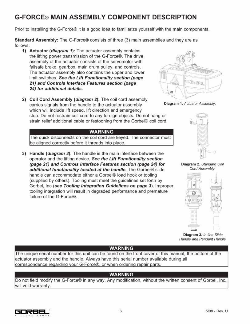
G-FORCE® MAIN ASSEMBLY COMPONENT DESCRIPTIONPrior to installing the G-Force® it is a good idea to familiarize yourself with the main components.
Standard Assembly: The G-Force® consists of three (3) main assemblies and they are asfollows: 1) Actuator (diagram 1): The actuator assembly contains the lifting power transmission of the G-Force®. The drive assembly of the actuator consists of the servomotor with failsafe brake, gearbox, main drum pulley, and controls. The actuator assembly also contains the upper and lower limit switches. See the Lift Functionality section (page 21) and Controls Interface Features section (page 24) for additional details.
2) Coil Cord Assembly (diagram 2): The coil cord assembly carries signals from the handle to the actuator assembly which will include lift speed, lift direction and emergency stop. Do not restrain coil cord to any foreign objects. Do not hang or strain relief additional cable or festooning from the Gorbel® coil cord.
3) Handle (diagram 3): The handle is the main interface between the operator and the lifting device. See the Lift Functionality section (page 21) and Controls Interface Features section (page 24) for additional functionality located at the handle. The Gorbel® slide handle can accommodate either a Gorbel® load hook or tooling (supplied by others). Tooling must meet the guidelines set forth by Gorbel, Inc (see Tooling Integration Guidelines on page 3). Improper tooling integration will result in degraded performance and premature failure of the G-Force®.
WARNINGThe quick disconnects on the coil cord are keyed. The connector must be aligned correctly before it threads into place.
WARNINGDo not field modify the G-Force® in any way. Any modification, without the written consent of Gorbel, Inc., will void warranty.
WARNINGThe unique serial number for this unit can be found on the front cover of this manual, the bottom of the actuator assembly and the handle. Always have this serial number available during allcorrespondence regarding your G-Force®, or when ordering repair parts.
Diagram 3A. Standard 300 KG Actuator AssemblyDiagram 1. Actuator Assembly.
Diagram 2. Standard Coil Cord Assembly.
Diagram 3. In-line Slide Handle and Pendant Handle.
6 5/08 - Rev. U

INSTALLATIONSTEP 1 - UNPACKING THE G-FORCE®
1.1 Carefully remove all items from the box.
1.2 Verify that all components listed on the packing slip are included.
1.3 If any items are missing or were damaged during shipping, please contact Gorbel® Inside Sales immediately at (800) 821-0086 or (585) 924-6262.
STEP 2 - PRE-ASSEMBLY / TOOLS REQUIRED
2.1 Read entire Operator’s Manual before beginning installation of the G-Force®.
2.2 Tools and materials (by others) typically needed to install/assemble a G-Force® are as follows: • 5mm Allen wrench • 19mm hex socket • 8mm Allen wrench • Plastic cable tie straps • 2.5mm Allen wrench • Ladders/man lifts • 6mm Allen wrench (1320 lb only) • 14mm wrench or hex socket (1320 lb. only) • 3mm Allen wrench (1320 lb only) • Snap ring pliers (1320 lb. only)
STEP 3 - ACTUATOR ASSEMBLY INSTALLATION
3.1 The standard G-Force® will come with the wheels pre-assembled to the actuator trolley (diagram 3A).
When a Gorbel® G-Force® is to be used on a non-Gorbel® bridge system, a universal adapter trolley is required (diagram 3B). Note: The customer must provide two (2) hoist trolleys when the unit will run in a non-Gorbel® bridge system.
3.2 Ensure the power cord from the actuator is facing the festooning side of the bridge/monorail. Remove the end stop from the bridge and install the G-Force® actuator into the track. Immediately reinstall the end stop. Verify that the G-Force® trolley wheels are correct for the style and capacity track that the unit is being installed on by rolling the actuator assembly along the full length of the bridge to ensure that the travel is smooth throughout.
TIP: Packing list can be found in plastic pocket attached to shipping box.
WARNINGDO NOT lift the actuator by grabbing the blue plastic end covers. To lift the actuator, grab the handle slots in the trolley.
Diagram 3A. Standard 300 KG Actuator AssemblyDiagram 3A. Standard Actuator Assembly.
Diagram 3B. Standard 300 KG Actuator Assembly with Universal Adapter TrolleyDiagram 3B. Standard Actuator Assembly
with Universal Adapter Trolley.
75/08 - Rev. U

STEP 4 - COIL CORD INSTALLATION (STANDARD IN-LINE SLIDE HANDLE, REMOTE MOUNTED SLIDE HANDLE & REMOTE MOUNTED PENDANT HANDLE)
Note: G-Force® units, standard in-line or remote mounted, that are ordered from the factory will be shipped with the coil cord assembled to the actuator wear ring and the coil cord footer, creating the coil cord assembly (diagrams 4A and 4B). In addition, units ordered with air power will have a 1/4” ID nycoil air hose coil cord assembled onto the coil cord assembly (not shown).
4.1 Verify the coil cord assembly is correct. There are two coil cord assemblies: standard and double length. The standard coil cord assembly is used on systems with a trolley saddle up to 14’ (4.27m) and will measure approximately 8.3” (211.46mm) in length. The double length coil cord assembly is used on systems with a trolley saddle greater than 14’ (4.27m) and will measure approximately 16.4” (415.93mm) in length.
4.2 Feed the wire rope from the actuator assembly through the center of the coil cord assembly.
4.3 Use the actuator assembly hardware to fasten the coil cord assembly to the actuator (diagram 4C). Adjust the coil cord in the clamps so that the coil cord connector is conveniently located on the proper side of the actuator assembly. Note: The orientation of the coil cord must be correct so that the connector is located properly (diagram 4D).
4.4 Thread the coil cord connector into the actuator connector (diagram 4D).
4.5 Assure that the coils of the coil cord are centered around the wire rope when properly installed.
4.6 Use the 16mm shoulder bolt and M12 jam-nut to retain the coil cord footer to the thimble in the wire rope. Note: The shoulder bolt and jam-nut will be used to retain the handle or collector in the next step.
4.7 If applicable, connect air hose coil cord to supply line from the actuator assembly. The air hose coil cord is provided with two (2) 1/4” NPT male swivel fittings located at both ends of the air hose.
4.8 For standard in-line slide handle or in-line force sensing handle installation, go to Step 5A, page 9. For remote mounted slide handle installation, go to Step 5B, page 9. For suspended pendant handle installation, go to Step 5C, page 11. For remote mounted pendant handle installation, go to Step 5D, page 11. For 1320 lb. in-line slide or remote mounted handle installation, go to Step 5E, page 13. For 1320 lb. suspended pendant handle installation, go to Step 5F, page 14. For remote mounted force sensing handle installation, go to Step 5H, page 15. For remote mounted force sensing hub handle installation, go to Step 5I, page 16.
TIP: This step is best completed once the actuator has been installed into the bridge system.
Diagram 4A. Standard Coil Cord Assembly.
Diagram 4B. Double Length Coil Cord
Assembly.
CAUTIONThe connectors on the coil cord are keyed. The connector must be aligned correctly before it threads into place.
Diagram 4D. Coil Cord Assembly Installation (Bottom).Diagram 4C. Coil Cord Assembly
Installation at the Actuator(black center not shown).
8 5/08 - Rev. U
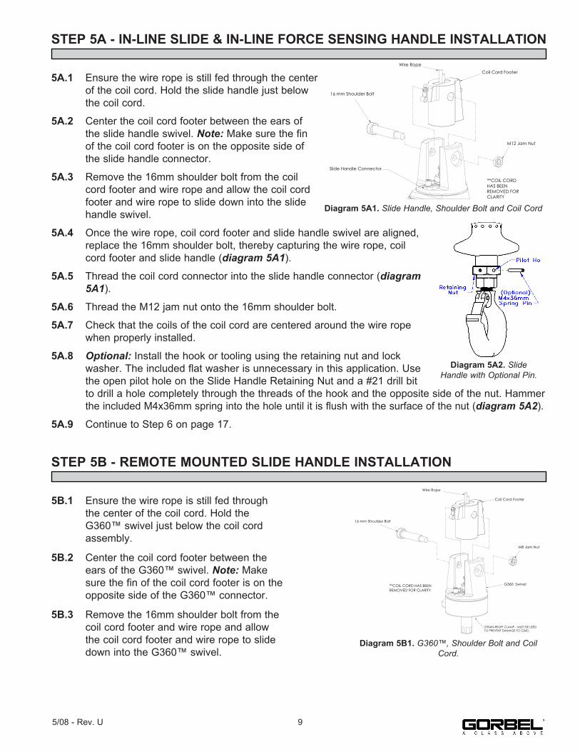
STEP 5A - IN-LINE SLIDE & IN-LINE FORCE SENSING HANDLE INSTALLATION
5A.1 Ensure the wire rope is still fed through the center of the coil cord. Hold the slide handle just below the coil cord.
5A.2 Center the coil cord footer between the ears of the slide handle swivel. Note: Make sure the fin of the coil cord footer is on the opposite side of the slide handle connector.
5A.3 Remove the 16mm shoulder bolt from the coil cord footer and wire rope and allow the coil cord footer and wire rope to slide down into the slide handle swivel.
5A.4 Once the wire rope, coil cord footer and slide handle swivel are aligned, replace the 16mm shoulder bolt, thereby capturing the wire rope, coil cord footer and slide handle (diagram 5A1).
5A.5 Thread the coil cord connector into the slide handle connector (diagram 5A1).
5A.6 Thread the M12 jam nut onto the 16mm shoulder bolt.
5A.7 Check that the coils of the coil cord are centered around the wire rope when properly installed.
5A.8 Optional: Install the hook or tooling using the retaining nut and lock washer. The included flat washer is unnecessary in this application. Use the open pilot hole on the Slide Handle Retaining Nut and a #21 drill bit to drill a hole completely through the threads of the hook and the opposite side of the nut. Hammer the included M4x36mm spring into the hole until it is flush with the surface of the nut (diagram 5A2).
5A.9 Continue to Step 6 on page 17.
STEP 5B - REMOTE MOUNTED SLIDE HANDLE INSTALLATION
5B.1 Ensure the wire rope is still fed through the center of the coil cord. Hold the G360™ swivel just below the coil cord assembly.
5B.2 Center the coil cord footer between the ears of the G360™ swivel. Note: Make sure the fin of the coil cord footer is on the opposite side of the G360™ connector.
5B.3 Remove the 16mm shoulder bolt from the coil cord footer and wire rope and allow the coil cord footer and wire rope to slide down into the G360™ swivel.
Diagram 5A. Slide Handle, Shoulder Bolt, Coil Cord.
16 mm Shoulder Bolt
M12 Jam Nut
Coil Cord FooterWire Rope
**COIL CORD HAS BEEN REMOVED FOR CLARITY
Slide Handle Connector
Diagram 5A1. Slide Handle, Shoulder Bolt and Coil Cord
M8 Jam Nut
Coil Cord Footer
Wire Rope
16 mm Shoulder Bolt
G360 Swivel**COIL CORD HAS BEEN REMOVED FOR CLARITY
Diagram 5B. G360, Shoulder Bolt, Coil Cord.
STRAIN-RELIEF CLAMP - MUST BE USED TO PREVENT DAMAGE TO G360.
Diagram 5B1. G360™, Shoulder Bolt and Coil Cord.
95/08 - Rev. U
Diagram 5A2. Slide Handle with Optional Pin.

STEP 5B - REMOTE MOUNTED SLIDE HANDLE INSTALLATION (CONTINUED)
5B.4 Once the wire rope, coil cord footer and G360™ swivel are aligned, replace the 16mm shoulder bolt thereby capturing the wire rope, coil cord footer and G360™ swivel (diagram 5B1, page 9).
5B.5 Thread the coil cord connector into the G360™ connector (diagram 5B1, page 9).
5B.6 Thread M12 jam nut onto the 16mm shoulder bolt.
5B.7 Check that the coils of the coil cord are centered around the wire rope when properly installed.
5B.8 A pilot hole is provided for the locking pin. Attach tooling to G360™ utilizing M16 thread. The tool bolt/rod thread should be beyond pilot hole of shaft when fully engaged. Using a #21 drill bit, drill through the tool bolt/rod thread and out the other side of G360™ shaft. Hammer pin into place thereby locking tooling to G360™ (diagram 5B2).
5B.9 Assemble the remote mounted slide handle inside the remote mount bracket using the hardware provided (diagram 5B3). Note: This step is best completed on a workbench prior to mounting handle to tooling.
5B.10 Attach the remote mounted handle with bracket to the tooling. Assure that the mounting arrangement does not affect the operating function of the slide handle.
5B.11 Connect the extension cable from the G360™ to the remote mounted slide handle. Securely clamp the remote mount coil cord extension cable to the tooling as needed.
5B.12 Continue to Step 6 on page 17.
WARNINGRemote mounted G-Force® handles must be mounted at both the top and bottom of the handle assembly. Failure to mount the remote mounted handle at top and bottom can result in poor performance and/or premature component failure.
Diagram 5H. Tooling Installation.
Diagram 5B2. Tooling Installation.
Diagram 5D. Remote Mounted Slide Handle, Exploded View
2x M16 Hex Head Cap Screw
2x M16 Lockwasher
2x M16 Flatwasher
Diagram 5B3. Remote Mounted Slide Handle,
Exploded View.
2X M16 Hexx 30mm Lg. Head Cap Screw
2X M16 Lockwasher2X M16 FlatwasherSlide Handle,
Remote Mounted Configuration
Remote Mount Slide Handle Bracket
CAUTIONTake care to avoid looping excess cable at locations where the loop could catch on foreign objects.
CAUTIONAll cables used in a remote mounted handle configuration must be properly clamped and/or strain-relieved to prevent premature failure of the G-Force® or customer tooling.
10 5/08 - Rev. U
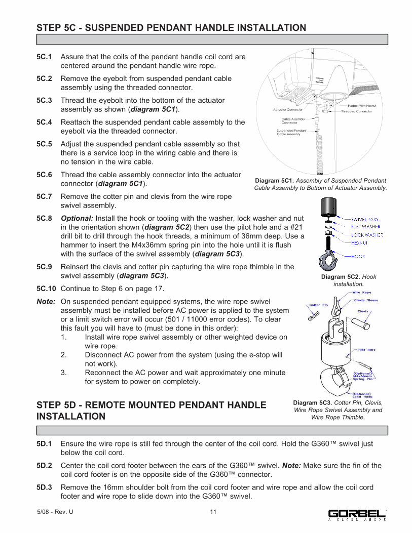
STEP 5C - SUSPENDED PENDANT HANDLE INSTALLATION
5C.1 Assure that the coils of the pendant handle coil cord are centered around the pendant handle wire rope.
5C.2 Remove the eyebolt from suspended pendant cable assembly using the threaded connector.
5C.3 Thread the eyebolt into the bottom of the actuator assembly as shown (diagram 5C1).
5C.4 Reattach the suspended pendant cable assembly to the eyebolt via the threaded connector.
5C.5 Adjust the suspended pendant cable assembly so that there is a service loop in the wiring cable and there is no tension in the wire cable.
5C.6 Thread the cable assembly connector into the actuator connector (diagram 5C1).
5C.7 Remove the cotter pin and clevis from the wire rope swivel assembly.
5C.8 Optional: Install the hook or tooling with the washer, lock washer and nut in the orientation shown (diagram 5C2) then use the pilot hole and a #21 drill bit to drill through the hook threads, a minimum of 36mm deep. Use a hammer to insert the M4x36mm spring pin into the hole until it is flush with the surface of the swivel assembly (diagram 5C3).
5C.9 Reinsert the clevis and cotter pin capturing the wire rope thimble in the swivel assembly (diagram 5C3).
5C.10 Continue to Step 6 on page 17.
Note: On suspended pendant equipped systems, the wire rope swivel assembly must be installed before AC power is applied to the system or a limit switch error will occur (501 / 11000 error codes). To clear this fault you will have to (must be done in this order): 1. Install wire rope swivel assembly or other weighted device on wire rope. 2. Disconnect AC power from the system (using the e-stop will not work). 3. Reconnect the AC power and wait approximately one minute for system to power on completely.
STEP 5D - REMOTE MOUNTED PENDANT HANDLE INSTALLATION
5D.1 Ensure the wire rope is still fed through the center of the coil cord. Hold the G360™ swivel just below the coil cord.
5D.2 Center the coil cord footer between the ears of the G360™ swivel. Note: Make sure the fin of the coil cord footer is on the opposite side of the G360™ connector.
5D.3 Remove the 16mm shoulder bolt from the coil cord footer and wire rope and allow the coil cord footer and wire rope to slide down into the G360™ swivel.
Eyebolt With Hexnut
Threaded Connector
Suspended Pendant Cable Assembly
Cable Assembly Connector
Actuator Connector
Diagram 5C1. Assembly of Suspended Pendant Cable Assembly to Bottom of Actuator Assembly.
Diagram 5C3. Cotter Pin, Clevis, Wire Rope Swivel Assembly and
Wire Rope Thimble.
115/08 - Rev. U
Diagram 5C2. Hookinstallation.

STEP 5D - REMOTE MOUNTED PENDANT HANDLE INSTALLATION (CONTINUED)
5D.4 Once the wire rope, coil cord footer and G360™ swivel are aligned, replace the 16mm shoulderbolt thereby capturing the wire rope, coil cord footer and G360™ swivel (diagram 5D1).
5D.5 Thread the coil cord connector into the G360™ connector (diagram 5D1).
5D.6 Thread the M12 jam nut onto the 16mm shoulder bolt.
5D.7 Check that the coils of the coil cord are centered around the wire rope when properly installed.
5D.8 A pilot hole is provided for the locking pin. Attach tooling to G360™ utilizing M16 thread. The tool bolt/rod thread should be beyond pilot hole of shaft when fully engaged. Using a #21 drill bit, drill through the tool bolt/rod thread and out the other side of G360™ shaft. Hammer pin into place thereby locking tooling to G360™ (diagram 5D2).
5D.9 Attach the pendant handle bracket directly to the tooling. Assure that the mounting arrangement does not affect the operating function of the pendant handle. Note: If necessary, a collar clamp mounting bracket option can be used to attach the pendant handle to the tooling (diagram 5D3).
5D.10 Connect the extension cable from the G360™ to the remote mounted pendant handle. Securely clamp the remote mount coil cord extension cable to the tooling as needed.
5D.11 Continue to Step 6 on page 17.
16 mm Shoulder Bolt
M8 Jam Nut
Wire Rope
Coil Cord Footer
G360 Swivel**COIL CORD HAS BEEN REMOVED FOR CLARITY
Diagram 5G. G360, Shoulder Bolt, Coil Cord
STRAIN-RELIEF CLAMP - MUST BE USED TO PREVENT DAMAGE TO G360.
Diagram 5D1. G360™, Shoulder Bolt and Coil Cord.
CAUTIONTake care to avoid looping excess cable at locations where the loop could catch onforeign objects.
CLAMP COLLAR
REMOTE MOUNTED PENDANT HANDLE
Diagram 5D3. Remote Mounted Pendant Handle with Collar Clamp Mounting Bracket (Option).
Diagram 5H. Tooling Installation.
Diagram 5D2. Tooling Installation.
CAUTIONAll cables used in a remote mounted handle configuration must be properly clamped and/or strain-relieved to prevent premature failure of the G-Force® or customer tooling.
12 5/08 - Rev. U
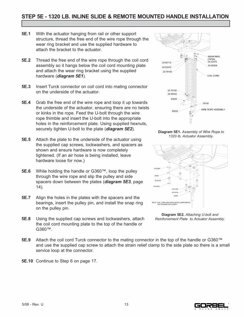
STEP 5E - 1320 LB. INLINE SLIDE & REMOTE MOUNTED HANDLE INSTALLATION
5E.1 With the actuator hanging from rail or other support structure, thread the free end of the wire rope through the wear ring bracket and use the supplied hardware to attach the bracket to the actuator.
5E.2 Thread the free end of the wire rope through the coil cord assembly so it hangs below the coil cord mounting plate and attach the wear ring bracket using the supplied hardware (diagram 5E1).
5E.3 Insert Turck connector on coil cord into mating connector on the underside of the actuator.
5E.4 Grab the free end of the wire rope and loop it up towards the underside of the actuator, ensuring there are no twists or kinks in the rope. Feed the U-bolt through the wire rope thimble and insert the U-bolt into the appropriate holes in the reinforcement plate. Using supplied hexnuts, securely tighten U-bolt to the plate (diagram 5E2).
5E.5 Attach the plate to the underside of the actuator using the supplied cap screws, lockwashers, and spacers as shown and ensure hardware is now completely tightened. (If an air hose is being installed, leave hardware loose for now.)
5E.6 While holding the handle or G360™, loop the pulley through the wire rope and slip the pulley and side spacers down between the plates (diagram 5E3, page 14).
5E.7 Align the holes in the plates with the spacers and the bearings, insert the pulley pin, and install the snap ring on the pulley pin.
5E.8 Using the supplied cap screws and lockwashers, attach the coil cord mounting plate to the top of the handle or G360™.
5E.9 Attach the coil cord Turck connector to the mating connector in the top of the handle or G360™ and use the supplied cap screw to attach the strain relief clamp to the side plate so there is a small service loop at the connector.
5E.10 Continue to Step 6 on page 17.
2X 65112
2X 03370
2X 79150
WEAR RING (76764)2X 03370
2X 65028
COIL CORD
2X 791502X 65032
83253
65032
79150
WIRE ROPE ASSEMBLY
Diagram 5E1. Assembly of Wire Rope to1320 lb. Actuator Assembly.
4X 83260
83252
4X 00195
4X 83236
83265
4X 02158
2X 01355
NOTE: COIL CORD AND ASSOCIATED COMPONENTS NOT SHOWN FOR CLARITY
Diagram 5E2. Attaching U-bolt and Reinforcement Plate to Actuator Assembly.
135/08 - Rev. U
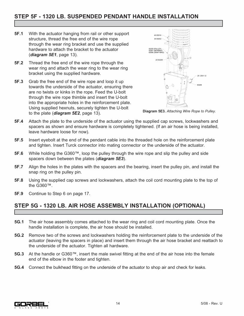
STEP 5F - 1320 LB. SUSPENDED PENDANT HANDLE INSTALLATION
5F.1 With the actuator hanging from rail or other support structure, thread the free end of the wire rope through the wear ring bracket and use the supplied hardware to attach the bracket to the actuator (diagram 5E1, page 13).
5F.2 Thread the free end of the wire rope through the wear ring and attach the wear ring to the wear ring bracket using the supplied hardware.
5F.3 Grab the free end of the wire rope and loop it up towards the underside of the actuator, ensuring there are no twists or kinks in the rope. Feed the U-bolt through the wire rope thimble and insert the U-bolt into the appropriate holes in the reinforcement plate. Using supplied hexnuts, securely tighten the U-bolt to the plate (diagram 5E2, page 13).
5F.4 Attach the plate to the underside of the actuator using the supplied cap screws, lockwashers and spacers as shown and ensure hardware is completely tightened. (If an air hose is being installed, leave hardware loose for now).
5F.5 Insert eyebolt at the end of the pendant cable into the threaded hole on the reinforcement plate and tighten. Insert Turck connector into mating connector or the underside of the actuator.
5F.6 While holding the G360™, loop the pulley through the wire rope and slip the pulley and side spacers down between the plates (diagram 5E3).
5F.7 Align the holes in the plates with the spacers and the bearing, insert the pulley pin, and install the snap ring on the pulley pin.
5F.8 Using the supplied cap screws and lockwashers, attach the coil cord mounting plate to the top of the G360™.
5F.9 Continue to Step 6 on page 17.
STEP 5G - 1320 LB. AIR HOSE ASSEMBLY INSTALLATION (OPTIONAL)
5G.1 The air hose assembly comes attached to the wear ring and coil cord mounting plate. Once the handle installation is complete, the air hose should be installed.
5G.2 Remove two of the screws and lockwashers holding the reinforcement plate to the underside of the actuator (leaving the spacers in place) and insert them through the air hose bracket and reattach to the underside of the actuator. Tighten all hardware.
5G.3 At the handle or G360™, insert the male swivel fitting at the end of the air hose into the female end of the elbow in the footer and tighten.
5G.4 Connect the bulkhead fitting on the underside of the actuator to shop air and check for leaks.
4X 65018
4X 65052
83255 (PULLEY)83261 (BEARING)65086 (SNAP RING)
2X 83259
2X 2001.12
83258
Diagram 5E3. Attaching Wire Rope to Pulley.
14 5/08 - Rev. U
STEP 5H - REMOTE MOUNT FORCE SENSING SLIDE HANDLE INSTALLATION
5H.1 Follow Steps 5B.1 through 5B.7 on pages 9 and 10 to install G360™.
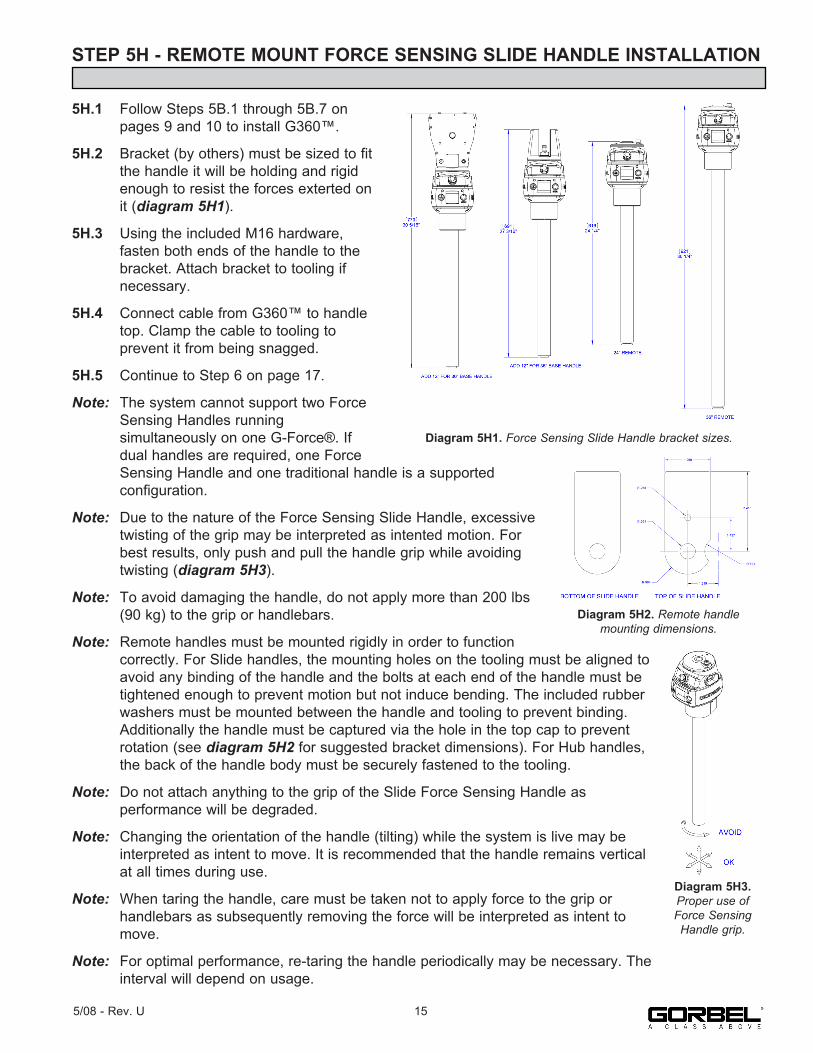
5H.2 Bracket (by others) must be sized to fit the handle it will be holding and rigid enough to resist the forces exterted on it (diagram 5H1).
5H.3 Using the included M16 hardware, fasten both ends of the handle to the bracket. Attach bracket to tooling if necessary.
5H.4 Connect cable from G360™ to handle top. Clamp the cable to tooling to prevent it from being snagged.
5H.5 Continue to Step 6 on page 17.
Note: The system cannot support two Force Sensing Handles running simultaneously on one G-Force®. If dual handles are required, one Force Sensing Handle and one traditional handle is a supported configuration.
Note: Due to the nature of the Force Sensing Slide Handle, excessive twisting of the grip may be interpreted as intented motion. For best results, only push and pull the handle grip while avoiding twisting (diagram 5H3).
Note: To avoid damaging the handle, do not apply more than 200 lbs (90 kg) to the grip or handlebars.
Note: Remote handles must be mounted rigidly in order to function correctly. For Slide handles, the mounting holes on the tooling must be aligned to avoid any binding of the handle and the bolts at each end of the handle must be tightened enough to prevent motion but not induce bending. The included rubber washers must be mounted between the handle and tooling to prevent binding. Additionally the handle must be captured via the hole in the top cap to prevent rotation (see diagram 5H2 for suggested bracket dimensions). For Hub handles, the back of the handle body must be securely fastened to the tooling.
Note: Do not attach anything to the grip of the Slide Force Sensing Handle as performance will be degraded.
Note: Changing the orientation of the handle (tilting) while the system is live may be interpreted as intent to move. It is recommended that the handle remains vertical at all times during use.
Note: When taring the handle, care must be taken not to apply force to the grip or handlebars as subsequently removing the force will be interpreted as intent to move.
Note: For optimal performance, re-taring the handle periodically may be necessary. The interval will depend on usage.
Diagram 5H1. Force Sensing Slide Handle bracket sizes.
Diagram 5H2. Remote handlemounting dimensions.
155/08 - Rev. U
Diagram 5H3. Proper use of Force Sensing Handle grip.
STEP 5I - REMOTE MOUNT FORCE SENSING HUB HANDLE INSTALLATION
5I.1 Follow Steps 5B.1 through 5B.7 on pages 9 and 10 to install G360™.
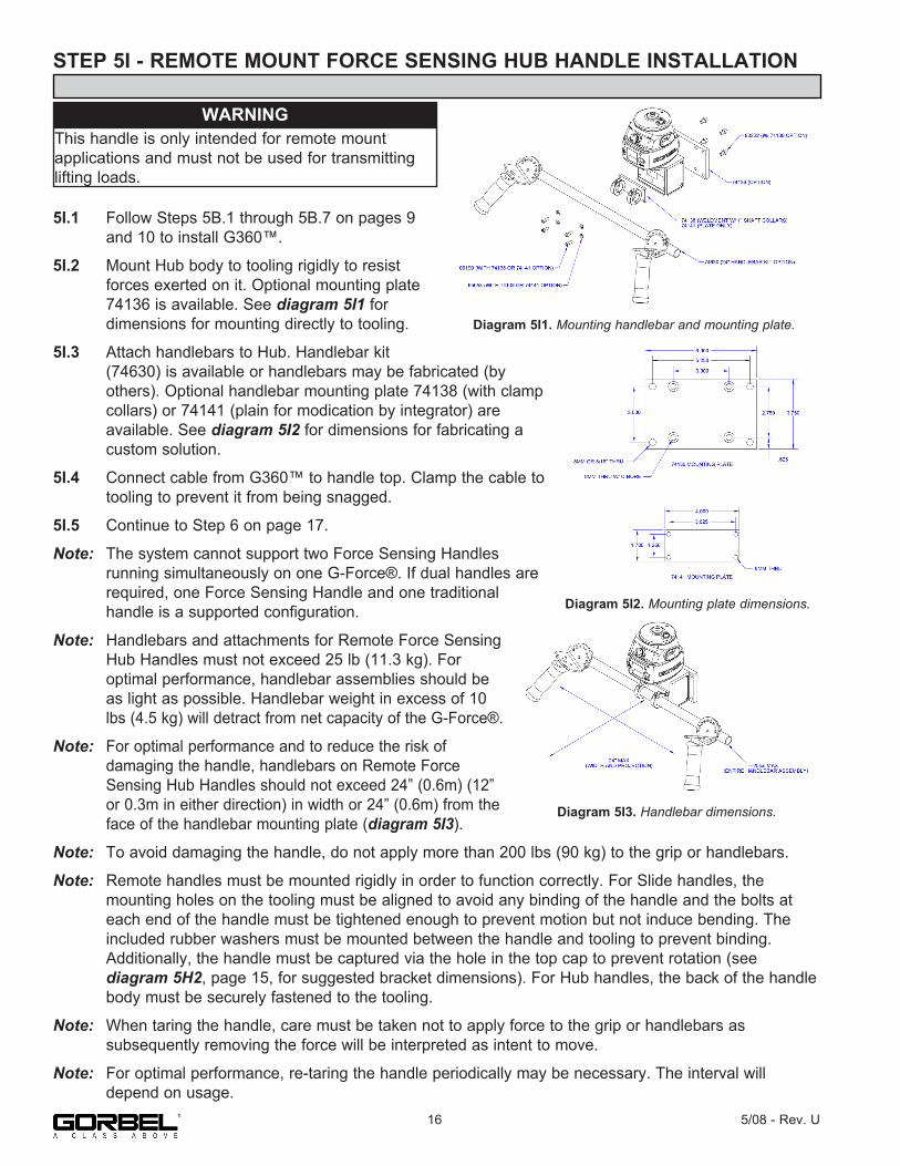
5I.2 Mount Hub body to tooling rigidly to resist forces exerted on it. Optional mounting plate 74136 is available. See diagram 5I1 for dimensions for mounting directly to tooling.
5I.3 Attach handlebars to Hub. Handlebar kit (74630) is available or handlebars may be fabricated (by others). Optional handlebar mounting plate 74138 (with clamp collars) or 74141 (plain for modication by integrator) are available. See diagram 5I2 for dimensions for fabricating a custom solution.
5I.4 Connect cable from G360™ to handle top. Clamp the cable to tooling to prevent it from being snagged.
5I.5 Continue to Step 6 on page 17.
Note: The system cannot support two Force Sensing Handles running simultaneously on one G-Force®. If dual handles are required, one Force Sensing Handle and one traditional handle is a supported configuration.
Note: Handlebars and attachments for Remote Force Sensing Hub Handles must not exceed 25 lb (11.3 kg). For optimal performance, handlebar assemblies should be as light as possible. Handlebar weight in excess of 10 lbs (4.5 kg) will detract from net capacity of the G-Force®.
Note: For optimal performance and to reduce the risk of damaging the handle, handlebars on Remote Force Sensing Hub Handles should not exceed 24” (0.6m) (12” or 0.3m in either direction) in width or 24” (0.6m) from the face of the handlebar mounting plate (diagram 5I3).
Note: To avoid damaging the handle, do not apply more than 200 lbs (90 kg) to the grip or handlebars.
Note: Remote handles must be mounted rigidly in order to function correctly. For Slide handles, the mounting holes on the tooling must be aligned to avoid any binding of the handle and the bolts at each end of the handle must be tightened enough to prevent motion but not induce bending. The included rubber washers must be mounted between the handle and tooling to prevent binding. Additionally, the handle must be captured via the hole in the top cap to prevent rotation (see diagram 5H2, page 15, for suggested bracket dimensions). For Hub handles, the back of the handle body must be securely fastened to the tooling.
Note: When taring the handle, care must be taken not to apply force to the grip or handlebars as subsequently removing the force will be interpreted as intent to move.
Note: For optimal performance, re-taring the handle periodically may be necessary. The interval will depend on usage.
Diagram 5I2. Mounting plate dimensions.
16 5/08 - Rev. U
Diagram 5I1. Mounting handlebar and mounting plate.
Diagram 5I3. Handlebar dimensions.
WARNINGThis handle is only intended for remote mountapplications and must not be used for transmitting lifting loads.

STEP 6 - ELECTRICAL POWER CONNECTION
STANDARD6.1 Prior to final wiring, inspect the entire system to ensure that all connections are seated properly and are without kinks or bends. Verify the following connections: a) Coil cord to handle or G360™ collector b) Coil cord to actuator assembly c) Extension cables (if included)
6.2 Connect a 220 VAC single-phase power source through a disconnect switch (by others) to the festooned power cabling (not provided with G-Force®).
6.3 Wire the female receptacle (provided) to the end of the festooned power cable.
6.4 After verifying the disconnect switch is turned OFF, connect the newly installed receptacle to the male plug at the G-Force®.
STEP 7 - INITIAL POWER-UP
7.1 Turn on the disconnect switch (by others) to apply power to the G-Force®. When power is detected, “POWER ON” is displayed on the LCD.
7.2 Disengage the emergency stop (E-stop) button located on the front face of the handle.
7.3 During the system power up the LCD at the handle will display “UNIT POWER-UP”. If you are using a Force Sensing Handle, after power is applied to the system and the unit has booted, fault 11009 will usually be displayed indicating that the handle needs to be tared. See page 30 for taring procedure.
7.4 Once the system is on-line and ready, “LIFT READY” will be displayed on the LCD.
7.5 • Standard Operation - Slide Handle Configuration: Grasp the handle grip to run the unit up and down. Do this several times to get a feel for the unit. The LCD displays RUN MODE HANDLE. • Standard Operation - Pendant Handle Configuration: Depress the up and down levers to run the unit up and down. Do this several times to get a feel for the unit. The LCD displays RUN MODE PENDANT. Note: The LCD backlight will shut off after 10 minutes of inactivity. See the Lift Functionality section on page 21 for complete details on handle operation.
7.6 Finally, test the operation of any special tooling that may have been integrated to the G-Force®.
TIP: Do not connect main power until all assembly is complete.
WARNINGIf your system displays drive faults 7219 and 4005 either when it powers on or when you attempt to lift or lower a load it means the AC power is too low. Even though the specification is 220 VAC +/- 10%, the power available at the system may be very close to the low end of the specification because of its proximity to the power source. The closer to the nominal 220 VAC you are supplying to the system the less likely you’ll experience any problems related to the AC voltage.
TIP: The operator should always keep their hand under the operator present sensor on the slide handle while operating the unit in standard mode. If the hand is frequently moved
away from the operator present sensor it will result in jerky movement from the unit.
TIP: Gorbel, Inc., does not provide integrated tooling for the G-Force®. All tooling related questions should be directed to the tooling manufacturer or supplier.
175/08 - Rev. U

STEP 8 - FLOAT MODE AND FINAL STEPS
8.1 Float Mode may be activated by simply pressing the G-Force® logo button on the left hand side of the handle (diagram 8A). Below is a simple exercise to practice if you are not familiar with the Float feature. (This exercise assumes an in-line slide handle is being used).
A) Grasp the handle grip and lift an object weighing at least 20 lbs. (9 kg) to a comfortable height in front of you.
B) Let go the of the handle grip.
C) Press the G-Force® logo button on the handle. Note: Do not hold onto the load. Applying an upward or downward force on the handle or load while initiating Float Mode will give the unit a false reading and cause excessive drift.
D) After Float Mode is initialized, the “blue” LED light will turn on and the handle with payload should not be moving. The LCD will display RUN MODE FLOAT.
E) Now grasp the load.
F) To move the load down, put vertical pressure on the load downward, towards the floor. To move the load up, lift up on the load, towards the ceiling. Note: The direction and speed of travel is now being controlled by the amount of force that the operator exerts directly onto the load. The higher the force exerted on the load, the faster the unit moves. Note: An over-speed detection routine checks if Float Mode reaches 90% of the maximum fully loaded lifting speed and shuts the unit down. It safely limits the maximum speed of travel in Float Mode.
G) Run the unit up and down several times (at least 20 times in each direction) to assure proper operation. Float Mode should provide a smooth feel.
H) Repeat this exercise until you become comfortable with Float Mode.
TIP: Gorbel® Inside Sales is available from 7am to 7pm Eastern Time Monday - Thursday and 7am to 5pm Eastern Time Friday.
EMERGENCY STOP BUTTON
G-FORCE LOGO BUTTON(FLOAT MODE) (OPTION)
MENU BUTTON
FAULT INDICATOR LED (RED)FLOAT INDICATOR LED (BLUE)
LCD DISPLAY
Diagram B. Slide Handle - G-FORCE LOGO, MENU, Emergency Stop buttons, LEDs
Diagram 8A. Float Mode Button - Slide Handle.
CAUTIONActuating the operator present switch while in Float Mode will cause the unit to exit Float.
18 5/08 - Rev. U
STEP 8 - FLOAT MODE AND FINAL STEPS (CONTINUED)
8.2 The speed, acceleration, and other features of the G-Force® can be adjusted using the Program Menu available at the handle. See the Program Mode section on page 25 for complete details on modifying and programming features.
8.3 Please contact the Gorbel® factory (585-924-6262) if any of the following occur. DO NOT ATTEMPT TO REPAIR UNIT YOURSELF.
• Excessive noise • Unexpected operation • Change in performance • Damage or excessive wear to unit components • Questions about the unit arise
Please do not be limited by these items only.
8.4 Keep Packing List, Installation & Operation Manual, Drawings, and any other inserts filed together in a safe place for future reference.
WARNINGNEVER remove the load from the G-Force® while still in Float Mode. The control system will interpret the removal of the load as operator intent to lift the load. Therefore, the unit will begin to drift up. The speed of the unit drift directly correlates to the weight that was removed from the unit. The heavier the weight, the faster the unit will travel.
WARNINGIn Float Mode, the live load weight CANNOT be increased or decreased because this will cause unwanted motion. Float Mode must be reinitiated each time the weight of the live load is changed.
CAUTIONIf external forces are applied to the load while Float Mode is being initiated, the G-Force® will calculate a baseline weight that is higher or lower than the actual weight being lifted. When the external force is removed, the load will begin to drift in the opposite direction of the load that was applied.
195/08 - Rev. U

STEP 9 - EXPANSION I/O BLOCK MOUNTING INSTRUCTIONS (OPTION)
DIMENSIONS
TIP: Expansion I/O block mounting instructions only apply to iQ units with an I/O block.
Diagram 9A. Expansion I/O block dimensions (millimeters).
Diagram 9B. Screw fastener drilling template.
20 5/08 - Rev. U
4253
85
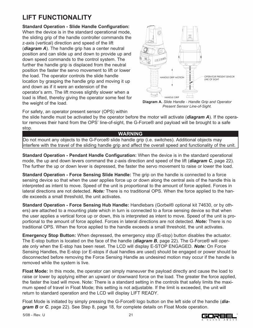
LIFT FUNCTIONALITYStandard Operation - Slide Handle Configuration: When the device is in the standard operational mode, the sliding grip of the handle controller commands the z-axis (vertical) direction and speed of the lift(diagram A). The handle grip has a center neutral position and can slide up and down to provide up and down speed commands to the control system. Thefurther the handle grip is displaced from the neutral position the faster the servo movement to lift or lower the load. The operator controls the slide handlelocation by grasping the handle grip and moving it up and down as if it were an extension of theoperator’s arm. The lift moves slightly slower when a load is lifted, thereby giving the operator some feel for the weight of the load.
For safety, an operator present sensor (OPS) within the slide handle must be activated by the operator before the motor will activate (diagram A). If the opera-tor removes their hand from the OPS’ line-of-sight, the G-Force® and payload will be brought to a safe stop.
Standard Operation - Pendant Handle Configuration: When the device is in the standard operational mode, the up and down levers command the z-axis direction and speed of the lift (diagram C, page 22). The further the up or down lever is depressed, the faster the servo movement to raise or lower the load.
Standard Operation - Force Sensing Slide Handle: The grip on the handle is connected to a force sensing device so that when the user applies force up or down along the central axis of the handle this is interpreted as intent to move. Speed of the unit is proportional to the amount of force applied. Forces in lateral directions are not detected. Note: There is no traditional OPS. When the force applied to the han-dle exceeds a small threshold, the unit activates.
Standard Operation - Force Sensing Hub Handle: Handlebars (Gorbel® optional kit 74630, or by oth-ers) are attached to a mounting plate which in turn is connected to a force sensing device so that when the user applies a vertical force up or down, this is interpreted as intent to move. Speed of the unit is pro-portional to the amount of force applied. Forces in lateral directions are not detected. Note: There is no traditional OPS. When the force applied to the handle exceeds a small threshold, the unit activates.
Emergency Stop Button: When depressed, the emergency stop (E-stop) button disables the actuator. The E-stop button is located on the face of the handle (diagram B, page 22). The G-Force® will oper-ate only when the E-stop has been reset. The LCD will display E-STOP ENGAGED. Note: On Force Sensing Handles, the E-stop (or E-stops if dual handles are used) should be engaged or power should be disconnected before removing the Force Sensing Handle as undesired motion may occur if the handle is removed while the system is live.
Float Mode: In this mode, the operator can simply maneuver the payload directly and cause the load to raise or lower by applying either an upward or downward force on the load. The greater the force applied, the faster the load will move. Note: There is a standard setting in the controls that safely limits the maxi-mum speed of travel in Float Mode; this setting is not adjustable. If the limit is exceeded, the unit will return to standard operation and the LCD will display LIFT READY.
Float Mode is initiated by simply pressing the G-Force® logo button on the left side of the handle (dia-gram B or C, page 22). See Step 8, page 18, for complete details on Float Mode operation.
Diagram A. Slide Handle - Handle Grip and Operator Present Sensor
HANDLE GRIP MOTION
HANDLE GRIP
OPERATOR PRESENT SENSORLINE OF SIGHT
Diagram A. Slide Handle - Handle Grip and Operator Present Sensor Line-of-Sight.
WARNINGDo not mount any objects to the G-Force® slide handle grip (i.e. switches). Additional objects mayinterfere with the travel of the sliding handle grip and affect the overall speed and functionality of the unit.
215/08 - Rev. U

LIFT FUNCTIONALITY (CONTINUED)Program Mode: In this mode, theoperator can control speed, acceleration, service features and other variable settings (diagram B or C). See the Program Mode section, page 25, for completeprogramming functionality located at the handle.
Float Mode LED (Blue): If the unit is equipped with Float Mode (option), the “Float Mode” enabled LED will illuminate when the G-Force® logo button is pressed on the hand controller and Float Mode has been cor-rectly initiated. This LED is located just above the G-Force® logo button (diagram B or C).
System Fault LED (Red): The “System Fault” LED flashes when basic faults have been detected by the control system. If a fault has occurred, the system will be disabled. This LED is located just above the MENU button (diagram B or C).
Diagnostic Mode: The Diagnostic Mode is aspecial program within the Program Mode under the Service menu that will allow a technician to measure or monitor the state of select switches and otherelectronic components in the actuator and either the slide or pendant handle. It is intended to be used for troubleshooting purposes only. The user can choose a single or multiple components. The E-stop must be cycled off/on to exit this particular program.
Overload: The servo controller will prevent the lift from moving upward if loaded beyond the maximum capacity of the G-Force®. When an overload condition is sensed the lift is prevented from moving upward. The red and blue LEDs will flash and LIFT OVERLOAD will be displayed on the LCD to indicate to the operator the unit is overloaded. The lift may be moved down to allow for the safe removal of the load.
Limit Switches: The G-Force® is equipped with both mechanical upper and lower limit switches, located in the actuator assembly. When the upper limit switch is triggered, the upward motion of the lift stops quickly at a controlled deceleration rate. The controlled deceleration rate guarantees the load cannot come off the hook. When the upper limit is triggered the lift will move down but not up. The lower limit is set so that a minimum of two full wraps of wire rope remain on the drum pulley at all times. When the lower limit switch is triggered, the downward motion of the lift stops quickly at a controlled deceleration rate. When the lower limit is triggered, the lift will only move up and not down.
EMERGENCY STOP BUTTON
G-FORCE LOGO BUTTON(FLOAT MODE) (OPTION)
MENU BUTTON
FAULT INDICATOR LED (RED)FLOAT INDICATOR LED (BLUE)
LCD DISPLAY
Diagram B. Slide Handle - G-FORCE LOGO, MENU, Emergency Stop buttons, LEDs
Diagram C. Pendant Handle - G-FORCE LOGO, MENU, Emergency Stop buttons, LEDs
UP LEVER (RAISE)DOWN LEVER (LOWER)
G-FORCE LOGO BUTTON(FLOAT MODE) (OPTION) MENU BUTTON
(PROGRAM MODE)
EMERGENCY STOP BUTTON
FAULT INDICATOR LED (RED)
FLOAT INDICATOR LED (BLUE)
LCD DISPLAY
Diagram B. Slide Handle - G-Force® Logo (Float Mode), MENUand Emergency-Stop Buttons and LEDs.
Diagram C. Pendant Handle - G-Force® Logo (Float Mode), MENU and Emergency-Stop Buttons and LEDs.
WARNINGIn Float Mode, the live load weight cannot be increased or decreased because this will cause unwanted motion. Float Mode must be reinitiated each time the weight of the live load is changed.
WARNINGEnabling the operator present sensor while in Float Mode will cause the unit to exit float.
22 5/08 - Rev. U

LIFT FUNCTIONALITY (CONTINUED)Slack Switch: The G-Force® is equipped with a slack switch that senses tension in the wire rope and trips when the wire rope develops slack. The switch is located inside the actuator assembly. When the slack switch senses slack in the wire rope, downward movement of the lift is stopped to minimize the amount of wire rope unwound from the drum pulley. When slack in the wire rope is sensed, the lift will only move up but not down.
Remote Mounted Handle (System Option): Thelifting device is capable of operating with the handledisplaced from the wire rope (not in-line with the wire rope). For example, if an end user has tooling that is too large for the operator to safely reach and operate the handle in the standard in-line position, remote mounting the handle is recommended. The tooling must be mounted (and balanced) on the end of the wire rope, while thehandle can be remote mounted to the tooling.
The remote mounted handle is linked to the coil cord via an
extension cable. The handle operates exactly the same as if it were mounted in-line. The
end user must supply Gorbel with the required length of the extension cable such that it can be safely routed and clamped to the tooling.
WARNINGThe tooling MUST be attached to the end of the wire rope with the G360™ swivel assembly (supplied by Gorbel, Inc.). Failure to mount the tooling with aswivel assembly can result in premature failure of both the wire rope and the coil cord.
Diagram D. Remote Mounted Slide Handle with Gorbel Bracket
REMOTE MOUNT BRACKET
Diagram D. Remote Mounted Slide Handle with Gorbel® Bracket.
CAUTIONAlways include the distance for bends and turns when providing the extension length.
WARNINGEnsure that the slide handle is supported properly in remote mounted handle applications by restraining the slide handle at both the top and bottom mounting points (diagram D).
WARNINGAll tooling must be retained to the G360™ assembly utiliz-ing the M16 thread and locking pin provided.
235/08 - Rev. U
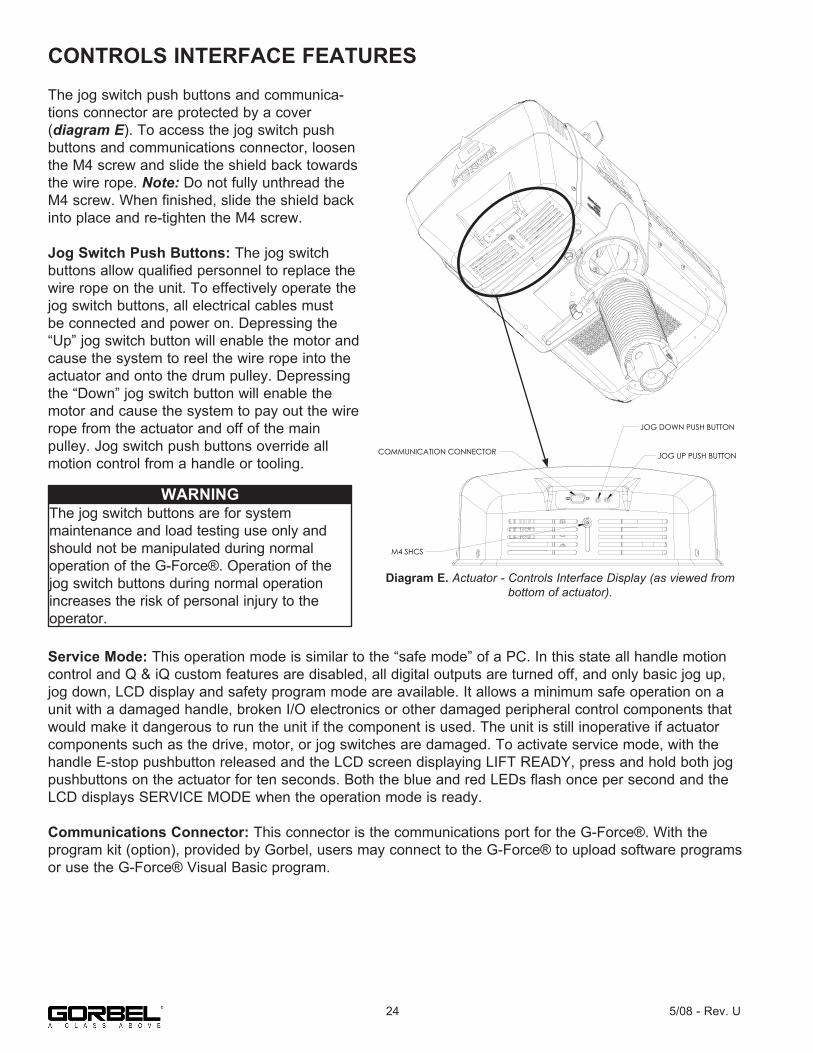
CONTROLS INTERFACE FEATURESThe jog switch push buttons and communica-tions connector are protected by a cover(diagram E). To access the jog switch push buttons and communications connector, loosen the M4 screw and slide the shield back towards the wire rope. Note: Do not fully unthread the M4 screw. When finished, slide the shield back into place and re-tighten the M4 screw.
Jog Switch Push Buttons: The jog switchbuttons allow qualified personnel to replace the wire rope on the unit. To effectively operate the jog switch buttons, all electrical cables must be connected and power on. Depressing the “Up” jog switch button will enable the motor and cause the system to reel the wire rope into the actuator and onto the drum pulley. Depressing the “Down” jog switch button will enable the motor and cause the system to pay out the wire rope from the actuator and off of the mainpulley. Jog switch push buttons override all motion control from a handle or tooling.
Service Mode: This operation mode is similar to the “safe mode” of a PC. In this state all handle motion control and Q & iQ custom features are disabled, all digital outputs are turned off, and only basic jog up, jog down, LCD display and safety program mode are available. It allows a minimum safe operation on a unit with a damaged handle, broken I/O electronics or other damaged peripheral control components that would make it dangerous to run the unit if the component is used. The unit is still inoperative if actuator components such as the drive, motor, or jog switches are damaged. To activate service mode, with the handle E-stop pushbutton released and the LCD screen displaying LIFT READY, press and hold both jog pushbuttons on the actuator for ten seconds. Both the blue and red LEDs flash once per second and the LCD displays SERVICE MODE when the operation mode is ready.
Communications Connector: This connector is the communications port for the G-Force®. With theprogram kit (option), provided by Gorbel, users may connect to the G-Force® to upload software programs or use the G-Force® Visual Basic program.
WARNINGThe jog switch buttons are for systemmaintenance and load testing use only and should not be manipulated during normal operation of the G-Force®. Operation of the jog switch buttons during normal operation increases the risk of personal injury to the operator.
Diagram E. Actuator - Control Interface (As viewed from Bottom of Actuator)
COMMUNICATION CONNECTOR
JOG DOWN PUSH BUTTON
JOG UP PUSH BUTTON
M4 SHCS
Diagram E. Actuator - Controls Interface Display (as viewed from bottom of actuator).
24 5/08 - Rev. U

PROGRAM MODEOverview (Software Version R1.07.6)Program Mode is used to control and adjust all of the features on the Q and iQ series G-Force®. Before entering Program Mode review the Program Mode Menu outline, Chart D, pages 30-35.
Note: Force Sensing Handles are not supported on units running software version R1.07.2 or earlier. Contact Gorbel for information on software updates.
Using Program ModeProgram Mode is initiated by following the steps below. Reference diagrams B and C on page 22 forbutton locations.
Entering Program Mode (chart A, page 27):1. Press and Hold the MENU button (right-hand side of handle) for two seconds to activate Program Mode.2. After two seconds, release the MENU button. The red and blue LEDs will illuminate and “PROGRAM MODE” will be displayed for one second. Then the first menu will be displayed. • Q unit: SPEED MENU (default). Note: If the Virtual Limits Package has been ordered, the Virtual Limits Menu (V-LIMITS) will appear first. • iQ unit: V-LIMITS MENU3. Press the MENU button to toggle between menus. The LCD will display the corresponding programmable menus: • V-LIMITS MENU - Virtual Limits menu (option) • SPEED MENU - Lift Speed adjustment • RESPONSE MENU - Lift Response (acceleration) adjustment • SETTINGS MENU - Programmable Features on both the Q and iQ units • SETTINGS MENU 2 - Programmable Features on iQ units only (iQ only) • LED MENU - Program the LED lights (iQ only) • SERVICE MENU - Customize and manage maintenance and service features • CONFIGUR MENU - Special unit features and hardware configurations4. Once you have reached the menu you would like to enter, press the G-Force® logo button.5. The first programmable feature in that menu will be displayed. Chart D, pages 30-35, displays a full list of all the menus and programmable features under each menu.6. To move to the second programmable feature press the G-Force® logo button again.7. Note: If the MENU button is pressed after Step 4, the selection is cleared and the LCD displays the next program menu.8. Once the desired feature is selected wait three seconds.9. After displaying the feature text for three seconds, the request is executed. The LCD will flash the feature text several times to indicate the command is being executed.10. After the command is executed, the system returns to standard operation, and the LCD displays “LIFT READY”.
255/08 - Rev. U
PROGRAM MODE (CONTINUED)
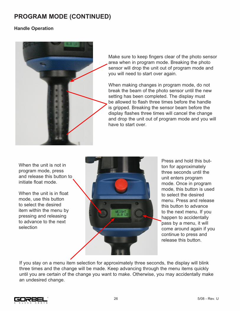
Handle Operation
Make sure to keep fingers clear of the photo sensor area when in program mode. Breaking the photo sensor will drop the unit out of program mode and you will need to start over again.
When making changes in program mode, do not break the beam of the photo sensor until the new setting has been completed. The display must be allowed to flash three times before the handle is gripped. Breaking the sensor beam before the display flashes three times will cancel the change and drop the unit out of program mode and you will have to start over.
When the unit is not in program mode, press and release this button to initiate float mode.
When the unit is in float mode, use this button to select the desired item within the menu by pressing and releasing to advance to the next selection
Press and hold this but-ton for approximately three seconds until the unit enters program mode. Once in program mode, this button is used to select the desired menu. Press and release this button to advance to the next menu. If you happen to accidentally pass by a menu, it will come around again if you continue to press and release this button.
If you stay on a menu item selection for approximately three seconds, the display will blink three times and the change will be made. Keep advancing through the menu items quickly until you are certain of the change you want to make. Otherwise, you may accidentally make an undesired change.
26 5/08 - Rev. U

Chart A. Program Mode Process.
275/08 - Rev. U
M
G
Press & Hold
Click
MENU Button
G-Force® Logo Button
M 2 sec to activate
PROGRAM MODE
V-LIMITSMENU N
iQ or Q with software option
Q iQ Only
G Set Various Virtual Limits
SPEEDMENU
MQ without software option
GSelect Maximum Hoist Speed
M
RESPONSE MENU G
Select Handle Control Response
M
SETTINGS MENU G
Program Common Q & iQ Custom Features
SETTINGS MENU 2 ~ N
G Program iQ FeaturesM
LEDMENU
M
M
SERVICE MENU G Select Maintenance and
Service Features
M
CONFIGUR MENU G
User Accessible Hardware Configurations
Activate Through CFG MENU ENABLE
G Configure Blue LED Indicator
DUAL ACT MENU
M
G[Optional] Configure Dual Actuator System
MFAST
ZERO FSH GZero FSH Weight (Shortcut)
M

PROGRAM MODE (CONTINUED)
Chart B. Program Mode Main Menu (Solid Border) and Sub-Menu (Dotted Border) Layouts.
28 5/08 - Rev. U
SETTINGS MENU
FM ANTI-RECOIL
FM SETUPSUB-MENU
USR OVLD SUB-MENU
CONFIGURMENU
RECORD CONFIG
M G
M G
M G
M
G
CHANGEOP FORCE
CHANGE OVLD LMT
M
G
M
G CHANGESENSITIV
M
G
TIMERSUB-MENU
M G
FLOAT MOTIMER
HANDLETIMER
M
G
M
G CUSTOM TIMER
M
G
FSHSUB-MENU
M G
CHANGE 2INLINE/
REMOTE
ZERO FSH WEIGHT
M
G
M
G SET FRCE2 LARGE/
SMALLM
G RESET FSH TARE
M
G
(If FSH)
DEFAULT SETTING
DEADBAND CENTER
M
G
M G
FM ANTI-RECOIL
M
G UNLOAD STOP ON
M
G
FM GAINS SUB-MENU
G M
CALIBRAT LOD COEF
ZERO LOD BIAS
M
G
M
G HARDWARE OPS ON
M
G
PRESET SUB-MENU
HARDWARE OPS OFF
M
G
M G
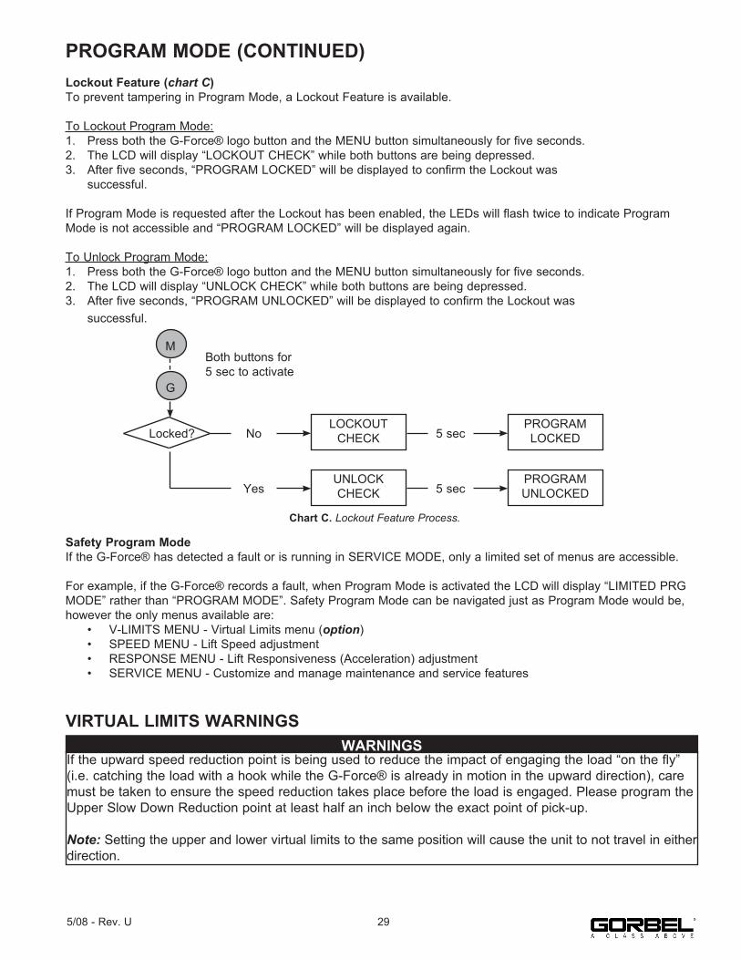
PROGRAM MODE (CONTINUED)Lockout Feature (chart C)To prevent tampering in Program Mode, a Lockout Feature is available.
To Lockout Program Mode:1. Press both the G-Force® logo button and the MENU button simultaneously for five seconds.2. The LCD will display “LOCKOUT CHECK” while both buttons are being depressed.3. After five seconds, “PROGRAM LOCKED” will be displayed to confirm the Lockout was successful.
If Program Mode is requested after the Lockout has been enabled, the LEDs will flash twice to indicate Program Mode is not accessible and “PROGRAM LOCKED” will be displayed again.
To Unlock Program Mode:1. Press both the G-Force® logo button and the MENU button simultaneously for five seconds.2. The LCD will display “UNLOCK CHECK” while both buttons are being depressed.3. After five seconds, “PROGRAM UNLOCKED” will be displayed to confirm the Lockout was successful.
Safety Program ModeIf the G-Force® has detected a fault or is running in SERVICE MODE, only a limited set of menus are accessible.
For example, if the G-Force® records a fault, when Program Mode is activated the LCD will display “LIMITED PRG MODE” rather than “PROGRAM MODE”. Safety Program Mode can be navigated just as Program Mode would be, however the only menus available are: • V-LIMITS MENU - Virtual Limits menu (option) • SPEED MENU - Lift Speed adjustment • RESPONSE MENU - Lift Responsiveness (Acceleration) adjustment • SERVICE MENU - Customize and manage maintenance and service features
VIRTUAL LIMITS WARNINGS
Chart C. Lockout Feature Process.
M
G
Locked? NoLOCKOUT
CHECK 5 secPROGRAM LOCKED
YesUNLOCK CHECK 5 sec
PROGRAM UNLOCKED
Both buttons for 5 sec to activate
If the upward speed reduction point is being used to reduce the impact of engaging the load “on the fly” (i.e. catching the load with a hook while the G-Force® is already in motion in the upward direction), care must be taken to ensure the speed reduction takes place before the load is engaged. Please program the Upper Slow Down Reduction point at least half an inch below the exact point of pick-up.
Note: Setting the upper and lower virtual limits to the same position will cause the unit to not travel in either direction.
WARNINGS
295/08 - Rev. U
PROGRAM MODE (CONTINUED)
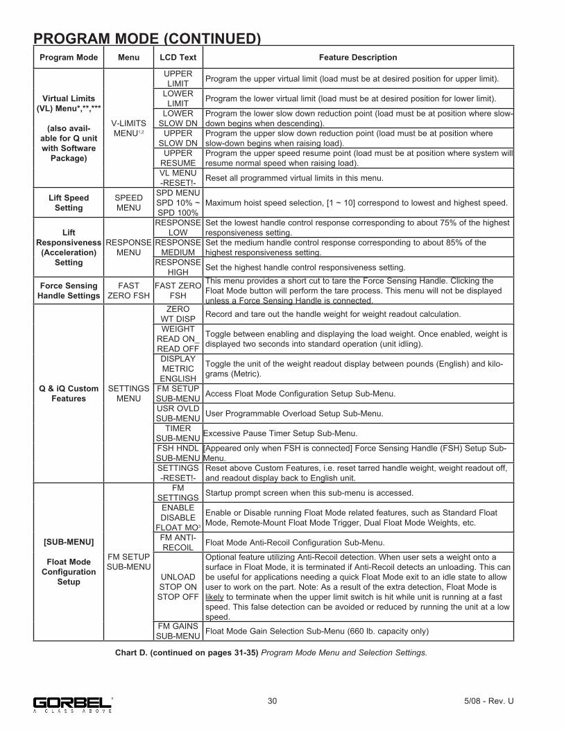
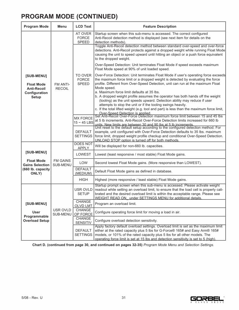
Chart D. (continued on pages 31-35) Program Mode Menu and Selection Settings.
Program Mode Menu LCD Text Feature Description
Virtual Limits(VL) Menu*,**,***
(also avail-able for Q unit with Software
Package)
V-LIMITSMENU1,2
UPPERLIMIT Program the upper virtual limit (load must be at desired position for upper limit).
LOWERLIMIT Program the lower virtual limit (load must be at desired position for lower limit).
LOWERSLOW DN
Program the lower slow down reduction point (load must be at position where slow-down begins when descending).
UPPERSLOW DN
Program the upper slow down reduction point (load must be at position where slow-down begins when raising load).
UPPERRESUME
Program the upper speed resume point (load must be at position where system will resume normal speed when raising load).
VL MENU-RESET!- Reset all programmed virtual limits in this menu.
Lift Speed Setting
SPEEDMENU
SPD MENUSPD 10% ~SPD 100%
Maximum hoist speed selection, [1 ~ 10] correspond to lowest and highest speed.
Lift Responsiveness
(Acceleration) Setting
RESPONSEMENU
RESPONSELOW
Set the lowest handle control response corresponding to about 75% of the highest responsiveness setting.
RESPONSEMEDIUM
Set the medium handle control response corresponding to about 85% of thehighest responsiveness setting.
RESPONSEHIGH Set the highest handle control responsiveness setting.
Force Sensing Handle Settings
FAST ZERO FSH
FAST ZERO FSH
This menu provides a short cut to tare the Force Sensing Handle. Clicking the Float Mode button will perform the tare process. This menu will not be displayed unless a Force Sensing Handle is connected.
Q & iQ Custom Features
SETTINGSMENU
ZEROWT DISP Record and tare out the handle weight for weight readout calculation.
WEIGHTREAD ON_READ OFF
Toggle between enabling and displaying the load weight. Once enabled, weight is displayed two seconds into standard operation (unit idling).
DISPLAYMETRIC
ENGLISH
Toggle the unit of the weight readout display between pounds (English) and kilo-grams (Metric).
FM SETUPSUB-MENU Access Float Mode Configuration Setup Sub-Menu.
USR OVLDSUB-MENU User Programmable Overload Setup Sub-Menu.
TIMERSUB-MENU Excessive Pause Timer Setup Sub-Menu.
FSH HNDL SUB-MENU
[Appeared only when FSH is connected] Force Sensing Handle (FSH) Setup Sub-Menu.
SETTINGS-RESET!-
Reset above Custom Features, i.e. reset tarred handle weight, weight readout off, and readout display back to English unit.
[SUB-MENU]
Float Mode Configuration
Setup
FM SETUPSUB-MENU
FMSETTINGS Startup prompt screen when this sub-menu is accessed.
ENABLEDISABLE
FLOAT MO3
Enable or Disable running Float Mode related features, such as Standard Float Mode, Remote-Mount Float Mode Trigger, Dual Float Mode Weights, etc.
FM ANTI-RECOIL Float Mode Anti-Recoil Configuration Sub-Menu.
UNLOADSTOP ONSTOP OFF
Optional feature utilizing Anti-Recoil detection. When user sets a weight onto asurface in Float Mode, it is terminated if Anti-Recoil detects an unloading. This can be useful for applications needing a quick Float Mode exit to an idle state to allow user to work on the part. Note: As a result of the extra detection, Float Mode is likely to terminate when the upper limit switch is hit while unit is running at a fast speed. This false detection can be avoided or reduced by running the unit at a low speed.
FM GAINS SUB-MENU Float Mode Gain Selection Sub-Menu (660 lb. capacity only)
30 5/08 - Rev. U
PROGRAM MODE (CONTINUED)
Chart D. (continued from page 30, and continued on pages 32-35) Program Mode Menu and Selection Settings.
315/08 - Rev. U
Program Mode Menu LCD Text Feature Description
[SUB-MENU]
Float Mode Anti-Recoil
Configuration Setup
FM ANTI-RECOIL
AT OVERFORCESPEED
Startup screen when this sub-menu is accessed. The correct configuredAnti-Recoil detection method is displayed (see next item for details on thedetection methods).
TO OVERFORCESPEED
Toggle Anti-Recoil detection method between standard over-speed and over-force detections. Anti-Recoil protects against a dropped weight while running Float Mode causing the unit to speed upward until hitting an object or a push force equivalent to the dropped weight.
Over-Speed Detection: Unit terminates Float Mode if speed exceeds maximum Float Mode speed at 90% of unit loaded speed.
Over-Force Detection: Unit terminates Float Mode if user’s operating force exceeds the maximum force limit or a dropped weight is detected by evaluating the forceprofile. Different from Over-Speed Detection, unit can run at the maximum Float Mode speed.a. Maximum force limit defaults at 35 lbs.b. A dropped weight profile assumes the operator has both hands off the weight (tooling) as the unit speeds upward. Detection ability may reduce if user attempts to stop the unit or if the tooling swings heavily.c. If the total lifted weight (e.g. tool and part) is less than the maximum force limit, Over-Speed Detection is applied.
MX FORCE15 ~ 45 LBS
Set Anti-Recoil Over-Force Detection maximum force limit between 15 and 45 lbs at 5 lb increments. Anti-Recoil Over-Force Detection limits increased for 660 lb units. New limits are between 30 and 90 lbs at 5 lb increments.
DEFAULT SETTINGS
Unit reset to the default setup according to the configured detection method. For example, unit configured with Over-Force Detection defaults to 35 lbs. maximum force limit, dropped weight profile checkup and conditional Over-Speed Detection. UNLOAD STOP option is turned off for both methods.
[SUB-MENU]
Float Mode Gains Selection(660 lb. capacity
ONLY)
FM GAINS SUB-MENU
DOES NOT APPLY Will be displayed for non-660 lb. capacities.
LOWEST Lowest (least responsive / most stable) Float Mode gains.
LOW Second lowest Float Mode gains. (More responsive than LOWEST).
DEFAULT (MEDIUM) Default Float Mode gains as defined in database.
HIGH Highest (more responsive / least stable) Float Mode gains.
[SUB-MENU]
User Programmable Overload Setup
USR OVLD SUB-MENU
USR OVLD SETUP
Startup prompt screen when this sub-menu is accessed. Please activate weight readout while setting an overload limit, to ensure that the load cell is properly cali-brated and the desired overload limit is within the acceptable range. Please see WEIGHT READ ON_ under SETTINGS MENU for additional details.
CHANGE OLVD LMT Program an overload limit.
CHANGE OP FORCE Configure operating force limit for moving a load in air.
CHANGE SENSITIV Configure overload detection sensitivity.
DEFAULT SETTINGS
Apply factory default overload settings. Overload limit is set as the maximum limit either at the rated capacity plus 5 lbs for G-Force® 165# and Easy Arm® 165# models, or 101% of the rated capacity plus 5 lbs for all other models. Theoperating force limit is set at 15 lbs and detection sensitivity is set to 5 (high).

PROGRAM MODE (CONTINUED)
Chart D. (continued from pages 30 & 31 & continued on pages 33-35) Program Mode Menu and Selection Settings.
32 5/08 - Rev. U
Program Mode Menu LCD Text Feature Description
Program an Overload Limit
CHANGE OVLD LMT
AT OVLD LBS NNNN
Startup prompt screen displaying the programmed overload limit. User Overload feature adjusts the detection and over limit parameters proportional to programmed Overload Limit. The over limit when overload is triggered is at M% above the Overload Limit plus the Operating Force Limit (see CHANGE OP FORCE section for info). An over limit is roughly set at: G-Force®: 102% x Overload Limit + OP FORCE EasyArm®: 105% x Overload Limit + OP FORCE
TAREOVLD LMT
Tare the total lifted weight as Overload Limit. When selected, unit tares the total lifted weight supported by the wire rope as the Overload Limit. This value can be monitored thru the weight readout feature without zeroing the reading (see SETTINGS MENU). The maximum limit is either the rated capacity plus 5 lbs for G-Force® 165# and Easy Arm 165# models, or 101% of the rated capacity plus 5 lbs for all other models. The minimum limit is 25% of the rated capacity. A warning is triggered if the tare weight is outside this range. Overload limit is capped at one of these bounds.
SET LIMITLBS NNNN
Set Overload Limit to the selected NNNN lbs limit. TARE OVLD LMT section lists a range of the maximum and minimum limits for Overload Limit. Clicking the G-Force® Logo pushbutton decrements the limit from the maximum down to the minimum, one lb at a time. The button can be pressed and held to decrease the count at a faster rate. Once the minimum value is reached, click the pushbutton to restart from the setup screen; otherwise, the minimum limit is applied after the pushbutton is released.
Configure Operating Force Limit for Moving
a Load in Air
CHANGEOP FORCE
AT FORCELBS NNNN
Startup prompt screen displaying the programmed Operating Force Limit. Operator’s push and pull force is an extra loading to the system, especially when handle is mounted on the tooling. This sub-menu allows one to set a Force Limit to account for different user’s operating force thus reducing chance of false overload detection. The limit should not be set larger than necessary as it reduces detection capability. By default, the limit is set at 15 lbs.
TO FORCE LBS NN Set Operating Force Limit to between 5 and 25 lbs in 1 lb increments.
Configure Overload Detection Sensitivity
CHANGE SENSITIV
AT LEVEL5 (HIGH) ~1 (LOW)
Startup prompt screen displaying the programmed Detection Sensitivity. This fea-ture may falsely detect varying weight as overloaded, for example, on a system with unbalanced or elongated tooling that sways easily during usage, or a less rigid supporting structure that induce much vibration. The sensitivity parameter can be reduced to prevent false detection when operating a load at no greater than the Overload Limit. However, do not reduce the sensitivity unless it is necessary due to actual usage. A reduced sensitivity increases the time to detect a legitimate overload condition that may result in damages or failure to the unit. By default, Detection Sensitivity is set at 5 (HIGH).
TO LEVEL5 (HIGH) ~1 (LOW)
Set Detection Sensitivity to between 5 (HIGH) and 1 (LOW) one level decrements at a time.
[SUB-MENU]
ExcessivePause Timer
Setup Sub-Menu
TIMERSUB-MENU3
PAUSE TIMER Startup prompt screen when this sub-menu is accessed.
HANDLE TIMER Change timer setting for the slide and pendant handles.
FLOAT MO TIMER Change timer setting for Float Mode.
CUSTOM TIMER
Change timer setting for custom motion such as Auto Home or a profiledmovement.
DEFAULT SETTINGS
Apply default excessive pause timer settings: slide and pendant handles (45seconds), Float Mode (60 seconds) and custom motion (20 seconds).
Change Time Setting for the Selected Run
Mode
HANDLE FLOAT MO
orCUSTOM
TIMER
AT LIMIT SEC NN MIN M
Startup prompt screen displaying the current timer limit between 1 ~ 59 seconds or 1 ~ 5, 10 or 15 minutes.
SET LIMIT SEC NN MIN M
Set pause timer limit.Clicking the G-Force® Logo pushbutton increments the setting from 1 to 59seconds, followed by 1 ~ 5, 10 or 15 minutes. Press-and-hold the pushbutton does a quick scroll-thru on these limits.

PROGRAM MODE (CONTINUED)
Chart D. (continued from pages 30-32, and continued on pages 34 & 35) Program Mode Menu and Selection Settings.
335/08 - Rev. U
Program Mode Menu LCD Text Feature Description
[SUB-MENU]
Force Sensing Handle Setup
Sub-Menu
FSH HNDL SUB-MENU
FSH HNDL SUB-MENU Startup prompt screen when this sub-menu is accessed.
ZERO FSH WEIGHT Tare the FSH handle bar weight to zero the load cell signal.CHANGE 2 INLINE
(REMOTE)
Change FSH style to remote if current style is inline (or inline if current style setting is remote).
SET FRCE 2 LARGE Change FSH Start up force to large if current setting is small (or vice versa).
RESET FSH TARE Reset FSH tare value to zero to un-zero the load cell signal.
DEADBAND CENTER FSH desdband averaging to improve sensitivity of FSH signal by centering it.
DEFAULT SETTINGS Apply default setting of FSH.
iQ Features*,** SETTINGSMENU 2
DUAL FM TOOL WT
(Float Mode feature enabled) Record tooling weight for the Dual Float Mode weights feature.
DUAL FMLOAD WT
(Float Mode feature enabled) Record tooling and load weights for the Dual Float Mode weights feature.
ANTIDROPTOOL WT
Tare tooling weight for anti-drop feature. The minimum difference between unload-ed and loaded tool weight is 20 lbs. for G-Force® and 25 lbs. for Easy Arm®.
MENU 2 SET HOME
Program the auto home tracking position (load must be at desired position for the limit).
MENU 2-RESET!-
Reset above custom features including the dual Float Mode, anti-drop, and auto home features.
LED Config Menu*,**:
Programs the blue LED as an
indicator)
LEDMENU
RESETLEDS
Disable any custom feature (e.g. anti-drop) from utilizing the blue LED as anindicator.
ANTIDROP
Enables the blue LED on the control handle to act as an indicator for the anti-drop function. When this function is enabled and the anti-drop output is off (off istypically the grip/clamp state of the tooling), the blue LED will flash until theanti-drop output turns on (on is typically the release state of the tooling).
SLACKANTIDROP
Set Slack Anti-Drop to use the blue LED for indication identical to ANTI-DROP above. This selection is not available by default because this is a disabled built-in feature.
Dual Actuator Configuration
Menu*,***
(Dual Actuator option required)
DUAL ACTMENU3
MOTIONINDEPEND
SYNC
Configure the dual actuators as synchronized or independent. This item is only selectable if the dual-actuator system is set to manual configuration, SETUP MANUAL.
SETUPMANUAL
AUTO
A dual-actuator system defaults to AUTO configuration, i.e. the systemautomatically configures the various run mode controls to INDEPEND or SYNC linking. If MANUAL option is selected, user can choose to overwrite some of the controls to a specific mode as programmed through MOTION INDEPEND\SYNC. The breakdowns are as such:RUN MODE AUTO MANUALJog Switch INDEPEND SELECTABLESlide Handle SYNC SELECTABLEPendant Handle SYNC SELECTABLEFloat Mode INDEPEND INDEPENDCustom Motion SYNC SELECTABLE
SETUP-RESET!-
Default dual-actuator feature settings to SYNC linking mode and AUTOconfiguration setup.
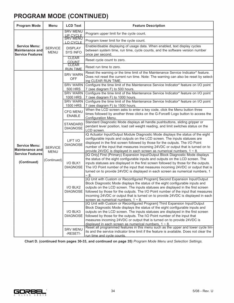
PROGRAM MODE (CONTINUED)
Chart D. (continued from pages 30-33, and continued on page 35) Program Mode Menu and Selection Settings.
34 5/08 - Rev. U
Program Mode Menu LCD Text Feature Description
Service Menu: Maintenance and Service Features
SERVICE MENU
SRV MENUUP CYCLE Program upper limit for the cycle count.SRV MENULO CYCLE Program lower limit for the cycle count.
DISPLAY SYS INFO
Enable/disable displaying of usage data. When enabled, text display cycles between system time, run time, cycle counts, and the software version number once per second.
CLEAR COUNT Reset cycle count to zero.CLEAR
RUN TIME Reset run time to zero.
Service Menu: Maintenance and Service Features
(Continued)
SERVICE MENU
(Continued)
SRV WARNOFF
Reset the warning or the time limit of the Maintenance Service Indicator* feature. Does not reset the current run time. Note: The warning can also be reset by select-ing CLEAR RUN TIME.
SRV WARN500 HRS
Configure the time limit of the Maintenance Service Indicator* feature on I/O point 7 (see diagram F) to 500 hours.
SRV WARN1000 HRS
Configure the time limit of the Maintenance Service Indicator* feature on I/O point 7 (see diagram F) to 1000 hours.
SRV WARN1500 HRS
Configure the time limit of the Maintenance Service Indicator* feature on I/O point 7 (see diagram F) to 1500 hours.
CFG MENUENABLE
When the LCD screen asks to enter a key code, click the Menu button three times followed by another three clicks on the G-Force® Logo button to access the Configuration Menu.
STANDARD DIAGNOSE
Standard Diagnostic Mode displays all handle pushbuttons, sliding gripper orpendant lever position, load cell weight reading, and limit switches status on the LCD screen.
LIFT I/ODIAGNOSE
iQ Actuator Input/Output Module Diagnostic Mode displays the status of the eight configurable inputs and outputs on the LCD screen. The inputs statuses aredisplayed in the first screen followed by those for the outputs. The I/O Pointnumber of the input that measures incoming 24VDC or output that is turned on to provide 24VDC is displayed in each screen as numerical numbers, 1 ~ 8.
I/O BLK1 DIAGNOSE
[iQ Only] First (Primary) Expansion Input/Output Block Diagnostic Mode displays the status of the eight configurable inputs and outputs on the LCD screen. The inputs statuses are displayed in the first screen followed by those for the outputs. The I/O Point number of the input that measures incoming 24VDC or output that is turned on to provide 24VDC is displayed in each screen as numerical numbers, 1 ~ 8.
I/O BLK2DIAGNOSE
[iQ Unit with Custom or Reconfigured Program] Second Expansion Input/Output Block Diagnostic Mode displays the status of the eight configurable inputs andoutputs on the LCD screen. The inputs statuses are displayed in the first screen followed by those for the outputs. The I/O Point number of the input that measures incoming 24VDC or output that is turned on to provide 24VDC is displayed in each screen as numerical numbers, 1 ~ 8.
I/O BLK3DIAGNOSE
[iQ Unit with Custom or Reconfigured Program] Third Expansion Input/Output Block Diagnostic Mode displays the status of the eight configurable inputs andoutputs on the LCD screen. The inputs statuses are displayed in the first screen followed by those for the outputs. The I\O Point number of the input thatmeasures incoming 24VDC or output that is turned on to provide 24VDC isdisplayed in each screen as numerical numbers, 1 ~ 8.
SRV MENU-RESET!-
Reset all programmed features in this menu such as the upper and lower cycle lim-its and the service indicator time limit if the feature is available. Does not clear the run time and cycle counts.
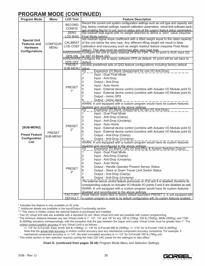
PROGRAM MODE (CONTINUED)
* Indicates this feature is only available on iQ units.** Additional details are available in the Input/Output Functionality section.*** This menu is hidden unless the optional feature is purchased and installed.1 Two (2) virtual limit sets are available with a standard iQ unit. More virtual limit sets are possible with custom programming.2 The minimum distance between any two Virtual Limits is 1”, 1/2”, 1/4” and 1/8” for any 165 lb (75Kg), 330 lb (150Kg), 660lb (300Kg), and 1320 lb (600Kg) actuators correspondingly, with the exception that the gap between the Upper and Lower Virtual Limits must be greater than 1”. The motion control position accuracy to any Virtual Limit is as follows: +/- 1/4” for G-Force®, Easy Arm® 330 lb (150Kg); +/- 1/8” for G-Force® 660 lb (300Kg), +/- 1/16” for G-Force® 1320 lb (600Kg) Note that the actual total accuracy is motion control accuracy plus any mechanical component accuracy constraints. For example, if mechanical component accuracy is +/- 1/4”, the total cumulated accuracy is +/- 1/2” for G-Force® 165 lb (75Kg unit.3 This entire section or item selection requires cycling the main 220 VAC power for the setting(s) to take effect.
355/08 - Rev. U
Chart D. (continued from pages 30-34) Program Mode Menu and Selection Settings.
Program Mode Menu LCD Text Feature Description
Special Unit Features and
Hardware Configurations
CONFIGURMENU
RECORDCONFIG
Record the current unit system configuration settings such as unit type and capacity set-ting, factory overload settings, loadcell calibration parameters, virtual limit software pack-age enabling flag for Q unit, burn-in status and all the custom feature setup parameters.
ZEROLOD BIAS
Set loadcell bias signal with no weight attached to define a “zero” value (requires Float Mode option).
CALIBRATLOD COEF
Set loadcell signal slope coefficient with a lifted weight equal to the rated capacity of the unit below the wire rope. Any different lifting weight will result in falsecalibration and inaccuracy such as weight readout feature (requires Float Mode option). This step must be performed after zero load bias.
HARDWARE OPS ON
Configure the unit to apply external OPS for FSH. The IO point is AUX input (Q) or X67 IO Block (iQ).
HARDWARE OPS OFF
Configure the unit to apply software OPS as default. IO point will be set back to default.
PRESET SUB-MENU
Access predefined sets of Q/iQ feature configurations including factory default setup.
[SUB-MENU]
Preset Feature Configuration
List
PRESET SUB-MENU3
PRESET1*
I/O Expansion I/O Block (Assignment for one I/O Anti-Drop)1 Input - Dual Float Mode2 Input - Anti-Drop3 Output - Anti-Drop4 Input - Auto Home5 Input - External device control (combine with Actuator I/O Module point 5)6 Input - External device control (combine with Actuator I/O Module point 6)7 Output - mimic OPS8 Output - mimic stackWARN: A unit equipped with a custom program would have its custom features disabled and reconfigured to the above settings.
PRESET2*
I/O Expansion I/O Block (Assignment for two I/O Anti-Drop)1 Input - Dual Float Mode2 Input - Anti-Drop (Clamp)3 Input - Anti-Drop (Unclamp)4 Input - Auto Home5 Input - External device control (combine with Actuator I/O Module point 5)6 Input - External device control (combine with Actuator I/O Module point 6)7 Output - Anti-Drop (Clamp)8 Output - Anti-Drop (Unclamp)WARN: A unit equipped with a custom program would have its custom features disabled and reconfigured to the above settings.
PRESET3*
I/O Expansion I/O Block (Two I/O Anti-Drop & System Switches Output)1 Input - Dual Float Mode2 Input - Anti-Drop (Clamp)3 Input - Anti-Drop (Unclamp)4 Input - Auto Home5 Output - Handle Operator Present Sensor Status6 Output - Slack or Down Travel Limit Switch Status7 Output - Anti-Drop (Clamp)8 Output - Anti-Drop (Unclamp)The external device control feature previously on I/O5 and 6 is disabled; therefore its corresponding outputs on Actuator I/O Module I/O points 5 and 6 are disabled as well.WARN: A unit equipped with a custom program would have its custom features disabled and reconfigured to the above settings.
FACTORY DEFAULT
Reset feature resets back to factory default equivalent PRESET 2. A unit equipped with a custom program is reset to its default configuration with its custom features enabled.

PROGRAM MODE (CONTINUED)
iQ Actuator Input/Output Module Functionality
I/O Point Assigned Function Description
Settings (see chart A for instructions on navigating
and setting menu functions)
1
Input - Dual virtuallimit sets
When this input is turned on, the G-Force® switches to a second independent set of virtual limits. See chart C for instructions on setting each of these limit sets.
Second set of virtual limits is done the same as the standard set but with this input on.
2Future expansion - no default functionality assigned
Functionality may be assigned via customprogramming to meet application requirements. Contact your Gorbel® dealer for more details.
3Future expansion - no default functionality assigned
Functionality may be assigned via customprogramming to meet application requirements. Contact your Gorbel® dealer for more details.
4Future expansion - no default functionality assigned
Functionality may be assigned via customprogramming to meet application requirements. Contact your Gorbel® dealer for more details.
5
Output - External device control (requires option-al expansion 8-point input/output block)
This output is controlled by input number 5 on the optional expansion 8-point input/output block. When that input is on, output 5 on the iQ actuator input/output module is on and vise versa.
6
Output - External device control (requires option-al expansion 8-point input/output block)
This output is controlled by input number 6 on the optional expansion 8-point input/output block. When that input is on, output 6 on the iQ actuator input/output module is on and vise versa.
7
Output - Serviceindicator
This output turns on when service is required (based on hours of use and set at the factory) and may be used to turn on an external service indicator (supplied by others).
The reset function for thisoutput is in the SERVICE MENU, items CLEAR RUN TIME or SRV WARN OFF.
8Output - Fault indicator This output turns on when a command fault or drive
fault occurs. It does not turn on due to a command warning.
Diagram F. Actuator CPU Input/Output Block.
Chart E. iQ Actuator Input/Output Module Standard Functionality.
36 5/08 - Rev. U
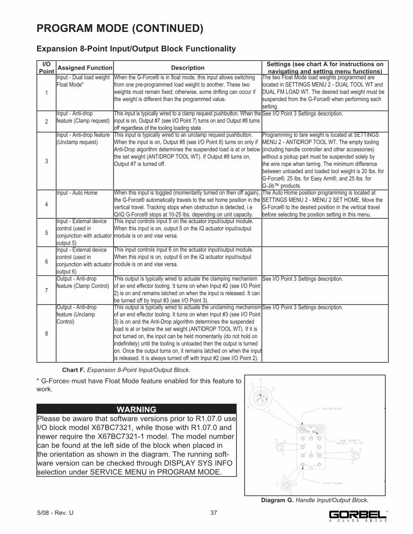
PROGRAM MODE (CONTINUED)
Expansion 8-Point Input/Output Block Functionality
* G-Force® must have Float Mode feature enabled for this feature to work.
Diagram G. Handle Input/Output Block.
I/O Point Assigned Function Description Settings (see chart A for instructions on
navigating and setting menu functions)
1
Input - Dual load weight Float Mode*
When the G-Force® is in float mode, this input allows switching from one pre-programmed load weight to another. These two weights must remain fixed; otherwise, some drifting can occur if the weight is different than the programmed value.
The two Float Mode load weights programmed are located in SETTINGS MENU 2 - DUAL TOOL WT and DUAL FM LOAD WT. The desired load weight must be suspended from the G-Force® when performing each setting.
2Input - Anti-dropfeature (Clamp request)
This input is typically wired to a clamp request pushbutton. When the input is on, Output #7 (see I/O Point 7) turns on and Output #8 turns off regardless of the tooling loading state.
See I/O Point 3 Settings description.
3
Input - Anti-drop feature (Unclamp request)
This input is typically wired to an unclamp request pushbutton. When the input is on, Output #8 (see I/O Point 8) turns on only if Anti-Drop algorithm determines the suspended load is at or below the set weight (ANTIDROP TOOL WT). If Output #8 turns on, Output #7 is turned off.
Programming to tare weight is located at SETTINGS MENU 2 - ANTIDROP TOOL WT. The empty tooling (including handle controller and other accessories)without a pickup part must be suspended solely by the wire rope when tarring. The minimum difference between unloaded and loaded tool weight is 20 lbs. forG-Force®, 25 lbs. for Easy Arm®, and 25 lbs. for G-Jib™ products.
4
Input - Auto Home When this input is toggled (momentarily turned on then off again), the G-Force® automatically travels to the set home position in the vertical travel. Tracking stops when obstruction is detected, i.eQ/iQ G-Force® stops at 10-25 lbs. depending on unit capacity.
The Auto Home position programming is located at SETTINGS MENU 2 - MENU 2 SET HOME. Move the G-Force® to the desired position in the vertical travel before selecting the position setting in this menu.
5
Input - External device control (used inconjunction with actuator output 5)
This input controls input 5 on the actuator input/output module. When this input is on, output 5 on the iQ actuator input/output module is on and vise versa.
6
Input - External device control (used inconjunction with actuator output 6)
This input controls input 6 on the actuator input/output module. When this input is on, output 6 on the iQ actuator input/output module is on and vise versa.
7
Output - Anti-dropfeature (Clamp Control)
This output is typically wired to actuate the clamping mechanism of an end effector tooling. It turns on when Input #2 (see I/O Point 2) is on and remains latched on when the input is released. It can be turned off by Input #3 (see I/O Point 3).
See I/O Point 3 Settings description.
8
Output - Anti-dropfeature (Unclamp Control)
This output is typically wired to actuate the unclamiing mechanism of an end effector tooling. It turns on when Input #3 (see I/O Point 3) is on and the Anti-Drop algorithm determines the suspended load is at or below the set weight (ANTIDROP TOOL WT). If it is not turned on, the input can be held momentarily (do not hold on indefinitely) until the tooling is unloaded then the output is turned on. Once the output turns on, it remains latched on when the input is released. It is always turned off with Input #2 (see I/O Point 2).
See I/O Point 3 Settings description.
Chart F. Expansion 8-Point Input/Output Block.
375/08 - Rev. U
Please be aware that software versions prior to R1.07.0 use I/O block model X67BC7321, while those with R1.07.0 and newer require the X67BC7321-1 model. The model number can be found at the left side of the block when placed in the orientation as shown in the diagram. The running soft-ware version can be checked through DISPLAY SYS INFO selection under SERVICE MENU in PROGRAM MODE.
WARNING
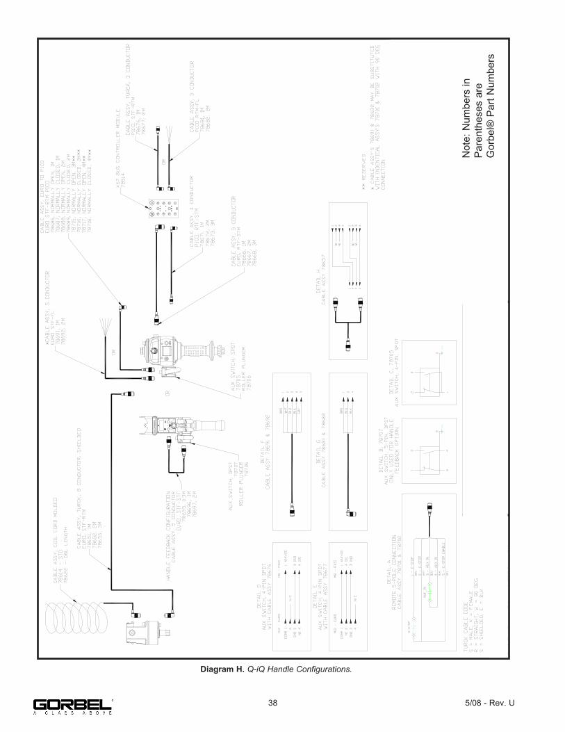
Diagram H. Q-iQ Handle Configurations.
Not
e: N
umbe
rs in
P
aren
thes
es a
re
Gor
bel®
Par
t Num
bers
38 5/08 - Rev. U

Diagram I. Actuator IO, 474 CPU.
395/08 - Rev. U

Diagram J. Handle IO Detail, Slide Model.
Not
e: N
umbe
rs in
P
aren
thes
es a
re
Gor
bel®
Par
t Num
bers
CA
BLE
AS
SY
(786
66) O
R S
IMIL
AR
CA
BLE
AS
SY
(786
71) O
R S
IMIL
AR
CA
BLE
AS
SY
, (78
681)
OR
SIM
ILA
R
CA
BLE
AS
SY
, (78
681)
OR
SIM
ILA
R
40 5/08 - Rev. U

Diagram K. Handle IO Detail, Pendant Model.
Not
e: N
umbe
rs in
P
aren
thes
es a
re
Gor
bel®
Par
t Num
bers
CA
BLE
AS
SY
, (78
681)
OR
SIM
ILA
R
CA
BLE
AS
SY
, (78
681)
OR
SIM
ILA
R
CA
BLE
AS
SY
(786
66) O
R S
IMIL
AR
CA
BLE
AS
SY
(786
71) O
R S
IMIL
AR
415/08 - Rev. U

TROUBLESHOOTINGBasic Troubleshooting
If possible solutions do not work, refer to the optional Service Manual available from Gorbel.
Failure Possible SolutionThere is no display on the LCD screen on the handle.
Note: The LCD screen will go into screen saver mode after 10 minutes of non-use.• Verify the correct AC power to the actuator.• Check the coil cord connections at both the handle and actuator.• Check the overall condition of the coil cord. Look for broken or exposed wiring.
There is a fault orwarning messagedisplayed on the LCD screen on the handle.
• Clear the fault per the instructions on the LCD.• Reset the E-stop on the handle.• Recycle the AC power. Note: AC power must be disconnected from the actuator by unplugging the actuator from the AC power source or disconnecting power by using a circuit breaker or similar method.
The red or blue LED, or both, on the control handle are either on or flashing.
• Refer to System Fault Diagnostics Charts on the following pages.
The unit will not raise or lower the load.
• Make sure you are in the RUN MODE.• Check the virtual limits settings if equipped with that option.• Check that you are not in an overloaded condition.• If you are wearing dark gloves, remove them and try the sliding handle again.• Check the coil cord connections at both the handle and the actuator.• Check that the sliding handle grip or pendant handle levers move smoothly.• Check for any interference between the handle and any foreign objects, work surfaces, etc.
The unit is too slow or too fast.
• Adjust the speed in PROGRAM MODE.• Check for speed reduction setting in virtual limits program if equipped with that option.
The unit does notaccelerate at the desired rate.
• Adjust the response in PROGRAM MODE.• Make sure you are not attempting to “snatch” the load.• Check the weight of the load. If you are close to the overload limit, try lifting at a reduced speed.
Unit will not raise or lower the load to the desired height.
• Check the virtual limits settings in PROGRAM MODE.• Check for wire rope damage.• Check whether or not you have an extended wire rope with a standard length coil cord.• Check to see if the wire rope has been modified (shortened) for any reason).• Check for any interference with foreign objects, tooling, work surfaces, etc.
The actuator isextremely noisy.
• Check the condition of the wire rope.• Check for any external damage to the actuator covers.
Float Mode does not function correctly.
Note: Refer to Technical Specifications, page 43, for maximum speed of G-Force® Float Mode.• Check that your system has the Float Mode option.• Check that the blue LED on the handle is illuminated.• Check to see if the LCD screen indicates you are in Float Mode.• Check that Float Mode has not timed out because the system has not been used for 60 seconds.• Ensure the unit is stable when Float Mode is initiated.• Check that the load data is reading accurately on the LCD screen.• Verify the bridge capacity. Check for excessive deflection in the bridge.• Check for obvious interference with the coil cord or handle.
Unit only goes in the up direction.
• Check the virtual limits settings if equipped with that option.• Check that the wire rope is not in a slack condition.• Check for any obvious interference with the load or the handle.• Check that you are not at the lower limit of the system.• Check the coil cord connections at both the handle and actuator.• Check the overall condition of the coil cord. Look for broken or exposed wiring.
Unit only goes in the down direction.
• Check the virtual limits settings if equipped with that option.• Check that you are not at the lower limit of the system.• Check that you are not in an overload condition.• Check for any obvious interference with the load or the handle.• Check the coil cord connections at both the handle and actuator.• Check the overall condition of the coil cord. Look for broken or exposed wiring.
7219 / 4005 codes. • The AC power is too low. If it approaches ~ 200VAC the system will not operate properly.501 / 11000 codes. • Limit switch fault:
1. Insure there is weight on the hook.2. Disconnect AC power.3. Reapply AC power.
########
• Two rows of # signs indicate poor cable connection anywhere from handle to the internal CPU.Check all external cable connections.
42 5/08 - Rev. U
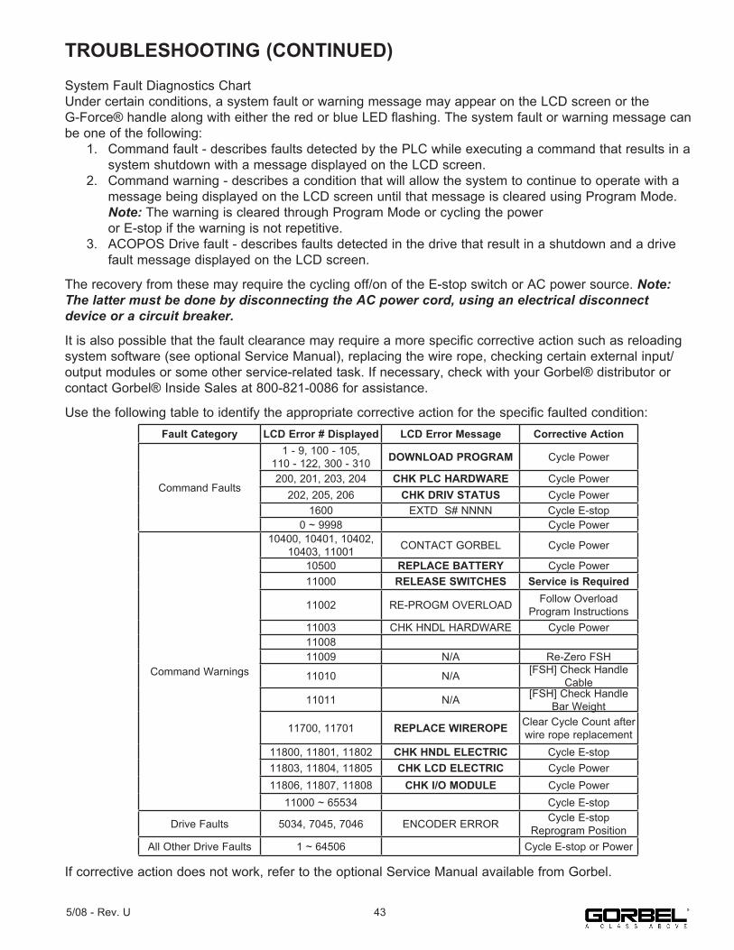
TROUBLESHOOTING (CONTINUED)System Fault Diagnostics ChartUnder certain conditions, a system fault or warning message may appear on the LCD screen or the G-Force® handle along with either the red or blue LED flashing. The system fault or warning message can be one of the following: 1. Command fault - describes faults detected by the PLC while executing a command that results in a system shutdown with a message displayed on the LCD screen. 2. Command warning - describes a condition that will allow the system to continue to operate with a message being displayed on the LCD screen until that message is cleared using Program Mode. Note: The warning is cleared through Program Mode or cycling the power or E-stop if the warning is not repetitive. 3. ACOPOS Drive fault - describes faults detected in the drive that result in a shutdown and a drive fault message displayed on the LCD screen.
The recovery from these may require the cycling off/on of the E-stop switch or AC power source. Note: The latter must be done by disconnecting the AC power cord, using an electrical disconnect device or a circuit breaker.
It is also possible that the fault clearance may require a more specific corrective action such as reloading system software (see optional Service Manual), replacing the wire rope, checking certain external input/output modules or some other service-related task. If necessary, check with your Gorbel® distributor or contact Gorbel® Inside Sales at 800-821-0086 for assistance.
Use the following table to identify the appropriate corrective action for the specific faulted condition:
If corrective action does not work, refer to the optional Service Manual available from Gorbel.
Fault Category LCD Error # Displayed LCD Error Message Corrective Action
Command Faults
1 - 9, 100 - 105,110 - 122, 300 - 310 DOWNLOAD PROGRAM Cycle Power
200, 201, 203, 204 CHK PLC HARDWARE Cycle Power202, 205, 206 CHK DRIV STATUS Cycle Power
1600 EXTD S# NNNN Cycle E-stop0 ~ 9998 Cycle Power
Command Warnings
10400, 10401, 10402, 10403, 11001 CONTACT GORBEL Cycle Power
10500 REPLACE BATTERY Cycle Power11000 RELEASE SWITCHES Service is Required
11002 RE-PROGM OVERLOAD Follow Overload Program Instructions
11003 CHK HNDL HARDWARE Cycle Power1100811009 N/A Re-Zero FSH
11010 N/A [FSH] Check Handle Cable
11011 N/A [FSH] Check Handle Bar Weight
11700, 11701 REPLACE WIREROPE Clear Cycle Count after wire rope replacement
11800, 11801, 11802 CHK HNDL ELECTRIC Cycle E-stop11803, 11804, 11805 CHK LCD ELECTRIC Cycle Power11806, 11807, 11808 CHK I/O MODULE Cycle Power
11000 ~ 65534 Cycle E-stop
Drive Faults 5034, 7045, 7046 ENCODER ERROR Cycle E-stopReprogram Position
All Other Drive Faults 1 ~ 64506 Cycle E-stop or Power
435/08 - Rev. U

TROUBLESHOOTING (CONTINUED)
LED Chart: The chart below shows the status of LED lights in different states.
ID Program State Sub-State Blue Red LCD Text Display
1 EngagedE-stop Off Off
Displays “E-STOP ENGAGED”. This state can also be used for troubleshooting if the E-stop is turned offintentionally.
2 Programming Mode On On
Overwrites fault, warning or service warning messages to allow correction of the cause of the messages. Displays “PROGRAM MODE”, various menu screens and selec-tion items. Please see “Program Mode” section for more details.
3 Fault Mode or Drive Fault Off On
LCD displays if unit is in command or drive fault, followed by a fault number and a corrective message. Unit is shut down until a corrective action is taken or cycling theE-stop or main AC power.
4 Warning Off Fast Flash
LCD displays unit is in warning fault, followed by a fault number and a corrective message. Unit is still allowed to run but warning messages overwrite other normalrunning messages defined in the latter cases.
5 Service Warning Fast Flash Off
Displays warnings for parts replacementrecommendations and those that require immediate attention, e.g. wire rope replacement or PLC low battery
6 Service Mode Slow Flash Slow Flash
Because SERVICE MODE is meant to run for special diagnostic purposes, it is shown before Service Warnings such as cycle count warnings. Multiple diagnosticmessages are likely to be displayed here such as output a live handle connection, pushbutton states (only aspecial Jog Mode is running), etc.
7 Startup Process
Before Ready Mode On On Displays “UNIT POWER UP”. Unit is starting up (power up)
and executing necessary settings and self diagnostics.
10.a
Run Mode
Overload Previous Slow Flash Indicates unit is overloaded (factory or user defined) while lifting.
10.b Still Motion Previous Slow FlashIndicates unit maintains still for an extensive time while running in a Run Mode application such as handle mode, Float Mode, etc.
10.c Over-Speed Previous Slow Flash Indicates Float Mode control exceeded the over speed limit and the unit is shutting down.
10.d
Handle Mode Previous Previous Displays run mode specific message such as RUN MODE JOG, HANDLE, PENDANT or CUSTOM
Float Mode On Off
Displays run mode specific messages such as“--RECORD-- --DATA--” and RUN MODE FLOAT. The first message indicates when the unit is collecting loadcell data to perform Float Mode.
11.aCustom
Feature #N
Display 1 On Off Displays custom feature messages for a custom motion feature (Run Mode) that also requires using LEDs for indication. More information may be found in the Custom Feature description section.
11.b Display 2 On On11.c Display 3 Slow Flash Off11.d Display 4 Off Slow Flash
20 Ready Mode Off Off Displays LIFT READY to indicate unit is idling and waiting for response.
20.aCustom
Feature #N
Display 1 On Off Displays custom feature messages for a custom feature that also requires using LEDs for indication while the unit is idling (in Ready Mode). More information may be found in the Custom Feature description section.
20.b Display 2 On On20.c Display 3 Slow Flash Off20.d Display 4 Off Slow Flash
44 5/08 - Rev. U

TECHNICAL SPECIFICATIONS
* -0.1% capacity per foot of travel from floor.
Series Q Series iQ Series Q Series iQ Series Q Series iQ Series Q Series iQ Series
Maximum Capacity (Load & Tool)
1320 lb 1320 lb 660 lb 660 lb 330 lb 330 lb 165 lb 165 lb600 kg 600 kg 300 kg 300 kg 150 kg 150 kg 75 kg 75 kg
Maximum Lifting Speed Unloaded
25 ft/min 25 ft/min 50 ft/min 50 ft/min 100 ft/min 100 ft/min 200 ft/min 200 ft/min7.47 m/min 7.47 m/min 14.94 m/min 14.94 m/min 30 m/min 30 m/min 61 m/min 61 m/min
Maximum Lifting Speed Fully Loaded
21 ft/min 21 ft/min 42 ft/min 42 ft/min 75 ft/min 75 ft/min 125 ft/min 125 ft/min6.40 m/min 6.40 m/min 12.80 m/min 12.80 m/min 23 m/min 23 m/min 38 m/min 38 m/min
Maximum Float Mode (Option) Lifting Speed
19 ft/min 19 ft/min 38 ft/min 38 ft/min 65 ft/min 65 ft/min 103 ft/min 103 ft/min5.79 5.79 m/min 11.58 m/min 11.58 m/min 20 m/min 20 m/min 31 m/min 31 m/min
Maximum Lift Range5.5 ft 5.5 ft 11 ft 11 ft 11 ft 11 ft 11 ft 11 ft
1.68 m 1.68 m 3.35 m 3.35 m 3.35 m 3.35 m 3.35 m 3.35 m
Maximum Lift Stroke5.5 ft 5.5 ft 8 ft 8 ft 8 ft 8 ft 8 ft 8 ft
1.68 m 1.68 m 2.44 m 2.44 m 2.44 m 2.44 m 2.44 m 2.44 mPrimary Lift Voltage (VAC) 220 +/- 10% 220 +/- 10% 220 +/- 10% 220 +/- 10% 220 +/- 10% 220 +/- 10% 220 +/- 10% 220 +/- 10%
Maximum Current (Amps) 6 6 6 6 6 6 6 6
Duty Cycle H5 H5 H5 H5 H5 H5 H5 H5Power Available for Tooling Not Available 24VDC @
0.5A Not Available 24VDC @ 0.5A Not Available 24VDC @
0.5A Not Available 24VDC @ 0.5A
Lifting Media
1/4” dia. 19x7 Preformed
Stainless Steel Wire Rope
1/4” dia. 19x7 Preformed
Stainless Steel Wire Rope
1/4” dia. 19x7 Preformed
Stainless Steel Wire Rope
1/4” dia. 19x7 Preformed
Stainless Steel Wire Rope
3/16” dia. 19x7 Preformed
Stainless Steel Wire Rope
3/16” dia. 19x7 Preformed
Stainless Steel Wire Rope
3/16” dia. 19x7 Preformed
Stainless Steel Wire Rope
3/16” dia. 19x7 Preformed
Stainless Steel Wire Rope
6.35mm dia. 19x7 Preformed Stainless Steel
Wire Rope
6.35mm dia. 19x7 Preformed Stainless Steel
Wire Rope
6.35mm dia. 19x7 Preformed Stainless Steel
Wire Rope
6.35mm dia. 19x7 Preformed Stainless Steel
Wire Rope
4.76mm dia. 19x7 Preformed Stainless Steel
Wire Rope
4.76mm dia. 19x7 Preformed Stainless Steel
Wire Rope
4.76mm dia. 19x7 Preformed Stainless Steel
Wire Rope
4.76mm dia. 19x7 Preformed Stainless Steel
Wire Rope
Operating Temperature Range
41 - 122° F 41 - 122° F 41 - 122° F 41 - 122° F 41 - 122° F 41 - 122° F 41 - 122° F 41 - 122° F5 - 50° C 5 - 50° C 5 - 50° C 5 - 50° C 5 - 50° C 5 - 50° C 5 - 50° C 5 - 50° C
Operating Humidity Range (Non-Condensing) 35 - 90% 35 - 90% 35 - 90% 35 - 90% 35 - 90% 35 - 90% 35 - 90% 35 - 90%
Virtual Limits (Upper Limit, Power Limit, Speed Reduction)
Optional Standard Optional Standard Optional Standard Optional Standard
Weight Display Accuracy (option with Float Mode)
+/- 1% Rated Capacity*
+/- 1% Rated Capacity*
+/- 1% Rated Capacity
+/- 1% Rated Capacity
+/- 1% Rated Capacity
+/- 1% Rated Capacity
+/- 1% Rated Capacity
+/- 1% Rated Capacity
UL/CSA Certified Optional Optional Optional Optional Optional Optional Optional Optional
CE Certified Yes Yes Yes Yes Yes Yes Yes Yes
I/O ActuatorNumber of Inputs, Type N/A 8, Sinking N/A 8, Sinking N/A 8, Sinking N/A 8, SinkingInput Current @ 24 VDC N/A 6ma N/A 6ma N/A 6ma N/A 6maNumber of Outputs, Type N/A 8, FET N/A 8, FET N/A 8, FET N/A 8, FETContinuous Current/Channel (Amps) N/A 0.5 N/A 0.5 N/A 0.5 N/A 0.5
Module Maximum Current (Amps) N/A 0.5 N/A 0.5 N/A 0.5 N/A 0.5
Handle with I/O ModuleNumber of Inputs, Type N/A 8, Sinking N/A 8, Sinking N/A 8, Sinking N/A 8, SinkingInput Current @ 24 VDC N/A 4ma N/A 4ma N/A 4ma N/A 4maNumber of Outputs, Type N/A 8, FET N/A 8, FET N/A 8, FET N/A 8, FETContinuous Current/Channel (Amps) N/A 0.5 N/A 0.5 N/A 0.5 N/A 0.5
Module Maximum Current (Amps) N/A 0.5 N/A 0.5 N/A 0.5 N/A 0.5
455/08 - Rev. U

WIRE ROPE INSPECTION1. Frequent Inspection The operator or other designated person should visually inspect all ropes at the start of each shift. These visual observations should be concerned with discovering gross damage, such as listed below, which may be an immediate hazard:
• distortion of the rope such as kinking, crushing, unstranding, birdcaging, main strand displacement, or core protrusion; • general corrosion; • broken or cut strands; • number, distribution, and type of visible broken wires (see next section on rope replacement).
When such damage is discovered, the rope shall either be removed from service or given an inspection as detailed in the next section.
2. Periodic Inspection The inspection frequency shall be determined by a qualified person and shall be based on such factors as expected rope life as determined by experience on the particular installation or similar installations; severity of environment; percentage of capacity lifts; frequency rates of operation; and exposure to shock loads. Inspections need not be at equal calendar intervals and should be more frequent as the rope approaches the end of its useful life.
A designated person shall perform periodic inspections. This inspection shall cover the entire length of rope. The individual outer wires in the strands of the rope shall be visible to this person during the inspection. Any deterioration resulting in appreciable loss of original strength, such as described below, shall be noted, and determination shall be made as to whether further use of the rope would constitute a hazard:
• points listed in previous section on frequent inspection; • reduction of rope diameter below nominal diameter due to loss of core support, internal or external corrosion, or wear of outside wires. • severely corroded or broken wires at end connections; • severely corroded, cracked, bent, worn, or improperly applied end connections.
Special care should be taken when inspecting sections of rapid deterioration, such as the following:
• sections in contact with saddles, equalizer sheaves, or other sheaves where rope travel is limited; • sections of rope at or near terminal ends where corroded or broken wires may protrude; • sections subject to reverse bends; • sections of ropes that are normally hidden during visual inspection, such as parts passing over sheaves.
46 5/08 - Rev. U
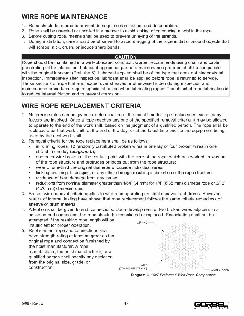
WIRE ROPE MAINTENANCE1. Rope should be stored to prevent damage, contamination, and deterioration.2. Rope shall be unreeled or uncoiled in a manner to avoid kinking of or inducing a twist in the rope.3. Before cutting rope, means shall be used to prevent unlaying of the strands.4. During installation, care should be observed to avoid dragging of the rope in dirt or around objects that will scrape, nick, crush, or induce sharp bends.
WIRE ROPE REPLACEMENT CRITERIA1. No precise rules can be given for determination of the exact time for rope replacement since many factors are involved. Once a rope reaches any one of the specified removal criteria, it may be allowed to operate to the end of the work shift, based on the judgment of a qualified person. The rope shall be replaced after that work shift, at the end of the day, or at the latest time prior to the equipment being used by the next work shift.2. Removal criteria for the rope replacement shall be as follows: • in running ropes, 12 randomly distributed broken wires in one lay or four broken wires in one strand in one lay (diagram L); • one outer wire broken at the contact point with the core of the rope, which has worked its way out of the rope structure and protrudes or loops out from the rope structure; • wear of one-third the original diameter of outside individual wires; • kinking, crushing, birdcaging, or any other damage resulting in distortion of the rope structure; • evidence of heat damage from any cause; • reductions from nominal diameter greater than 1/64” (.4 mm) for 1/4” (6.35 mm) diameter rope or 3/16” (4.76 mm) diameter rope.3. Broken wire removal criteria applies to wire rope operating on steel sheaves and drums. However, results of internal testing have shown that rope replacement follows the same criteria regardless of sheave or drum material.4. Attention shall be given to end connections. Upon development of two broken wires adjacent to a socketed end connection, the rope should be resocketed or replaced. Resocketing shall not be attempted if the resulting rope length will be insufficient for proper operation.5. Replacement rope and connections shall have strength rating at least as great as the original rope and connection furnished by the hoist manufacturer. A rope manufacturer, the hoist manufacturer, or a qualified person shall specify any deviation from the original size, grade, or construction.
CAUTIONRope should be maintained in a well-lubricated condition. Gorbel recommends using chain and cablepenetrating oil for lubrication. Lubricant applied as part of a maintenance program shall be compatible with the original lubricant (PreLube 6). Lubricant applied shall be of the type that does not hinder visual inspection. Immediately after inspection, lubricant shall be applied before rope is returned to service. Those sections of rope that are located over sheaves or otherwise hidden during inspection andmaintenance procedures require special attention when lubricating ropes. The object of rope lubrication is to reduce internal friction and to prevent corrosion.
WIRE(7 WIRES PER STRAND)
STRAND
CORE STRAND
Diagram F. - 19x7 Preformed Wire Rope Composition
Diagram L. 19x7 Preformed Wire Rope Composition.
475/08 - Rev. U

WIRE ROPE REPLACEMENT INSTRUCTIONS
Removal of Existing Wire Rope:1. Make sure the replacement rope is same length as rope currently on actuator unit. A. Ensure there is no load on handle, weighted load hook (pendant) or end effector. B. If using slow down setting, clear (reset) on handle or pendant handle menu screen. If using virtual limits, clear (reset) on handle or the pendant handle’s menu screen. C. Remove end tool. a. Slide handle: Using a 24mm socket and ratchet, remove the nut from the handle’s socket head shoulder screw, then use an M8 hex wrench and remove (unthread) socket head shoulder screw from handle. This will detach it from wire rope thimble. Set handle down on bench or table to support it and not stretch coil cord. b. Pendant handle: Remove the weighted hook or end effector from rope removing the clip and pin and set aside.2. Using a 3mm hex wrench, completely remove the four button head screws on front cover.3. Remove front cover from actuator and set aside upward to use as a bowl to hold future parts. Note: Be careful not to contact circuit board.4. Going in the down direction, unspool rope from drum using jog down button while keeping tension on wire rope with other hand wearing a glove. Continue until lower limit is engaged.5. Insert a medium sized screwdriver between the white colored wear ring and the actuator black casting where the wire rope exits the actuator (right side). This will keep the slack switch disengaged while jogging down the remainder of the rope (diagram M).6. Face the unit with circuit board on your left and wire rope on the right.
Note: The next two steps must be done at the same time.
7. Using a long screwdriver or hex wrench, reach through front of actuator and locate upper socket head cap screw head facing you underneath the lower limit switch. Fully push the screw in until it cannot move anymore (it is spring loaded). Keep pressure on it (diagram N).8. Using your right hand, press the jog down button while watching the drum rotate two full turns in the clockwise direction. The drum should stop automatically with the wire rope retainer visible at the 3 o’clock position on the drum.
WARNINGWire rope replacement is to be performed by qualified maintenance personnel only.
Diagram M.Insert screwdriver between the
white wear ring and the actuator casting where the rope exits the
actuator.
Diagram N.Locate socket head cap screw
head and fully push it in until it can not move anymore.
Limit Switch
Spring Loaded
Screw
48 5/08 - Rev. U
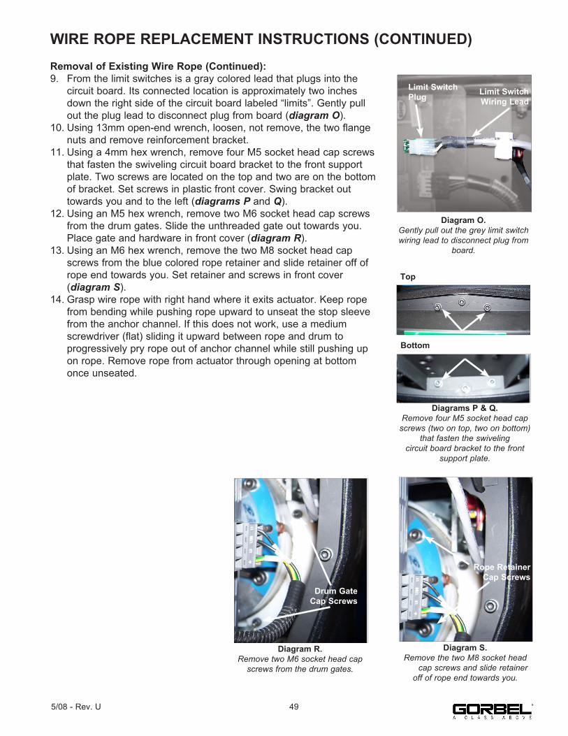
WIRE ROPE REPLACEMENT INSTRUCTIONS (CONTINUED)Removal of Existing Wire Rope (Continued):9. From the limit switches is a gray colored lead that plugs into the circuit board. Its connected location is approximately two inches down the right side of the circuit board labeled “limits”. Gently pull out the plug lead to disconnect plug from board (diagram O).10. Using 13mm open-end wrench, loosen, not remove, the two flange nuts and remove reinforcement bracket.11. Using a 4mm hex wrench, remove four M5 socket head cap screws that fasten the swiveling circuit board bracket to the front support plate. Two screws are located on the top and two are on the bottom of bracket. Set screws in plastic front cover. Swing bracket out towards you and to the left (diagrams P and Q).12. Using an M5 hex wrench, remove two M6 socket head cap screws from the drum gates. Slide the unthreaded gate out towards you. Place gate and hardware in front cover (diagram R).13. Using an M6 hex wrench, remove the two M8 socket head cap screws from the blue colored rope retainer and slide retainer off of rope end towards you. Set retainer and screws in front cover (diagram S).14. Grasp wire rope with right hand where it exits actuator. Keep rope from bending while pushing rope upward to unseat the stop sleeve from the anchor channel. If this does not work, use a medium screwdriver (flat) sliding it upward between rope and drum to progressively pry rope out of anchor channel while still pushing up on rope. Remove rope from actuator through opening at bottom once unseated.
Diagrams P & Q.Remove four M5 socket head cap
screws (two on top, two on bottom) that fasten the swiveling
circuit board bracket to the front support plate.
Top
Bottom
Diagram R.Remove two M6 socket head cap
screws from the drum gates.
Drum Gate Cap Screws
Diagram S.Remove the two M8 socket head cap screws and slide retainer
off of rope end towards you.
Rope Retainer Cap Screws
Diagram O.Gently pull out the grey limit switch wiring lead to disconnect plug from
board.
Limit Switch Wiring Lead
Limit Switch Plug
495/08 - Rev. U
WIRE ROPE REPLACEMENT INSTRUCTION (CONTINUED)Installation of New Wire Rope:1. Grasp anchor end of rope (not thimble) and make a crimp in gloved hand approximately three inches from the end (try to kink rope to make a bend radius).2. Insert the rope into the actuator up through the wear ring using right hand while seating the end crimp into the locker with your left hand. This will involve seating the rope into the radius channel afterwards.3. Pull down on the rope at the exit location of the actuator to seat the crimp into the locker fully.4. Install the rope retainer plate over the rope end and install the two M8 socket head cap screws and lockwashers. Torque hardware to fully compress lockwashers.5. Ensure that rope is seated in radius channel and install rope gate back in the unit making sure the rope guide (cutout) side is inserted first and the ends are sliding on guide rails freely. Fasten the rope gate assembly together using the previously removed hardware. Torque hardware to compress lockwashers.6. Install (slide) the reinforcement bracket studs into channels and tighten the two 13mm flange nuts. Next, swing circuit board bracket closed towards plate and fasten to plate using the four previously removed socket head cap screws and lockwashers. Torque hardware to compress lockwashers.7. Plug limit switch lead into circuit board “limits” receptacle making sure retention tab on plug is facing you.8. Using a clean cotton cloth wrapped around rope loosely near actuator entrance, pull down on rope and press jog up button allowing rope to pass through cloth cleaning it as it is being wrapped onto the drum. Continue loading rope onto drum using jog button until three drum revolutions are completed.9. Remove screwdriver from between actuator and wear ring.10. Install front cover onto actuator making sure all four screws are aligned with tabs before threading.11. If using coil cord, make sure rope is inserted down through the middle of the coils.12. Attach wire rope to handle, weighted hook, or end effector in reverse order of disassembly.13. Reset virtual limits and/or slow down settings.
1320 LB. WIRE ROPE REPLACEMENT INSTRUCTIONS1. Disconnect handle or G360™ from wire rope by disconnecting coil cord and/or air hose (if applicable), removing coil cord mounting plate, and removing pulley pin.2. Remove fasteners holding the reinforcement plate to the bottom of the actuator and nuts holding the U-bolt, freeing the end of the wire rope.3. Follow normal wire rope change procedure.4. Reverse steps once new wire rope is installed.
50 5/08 - Rev. U
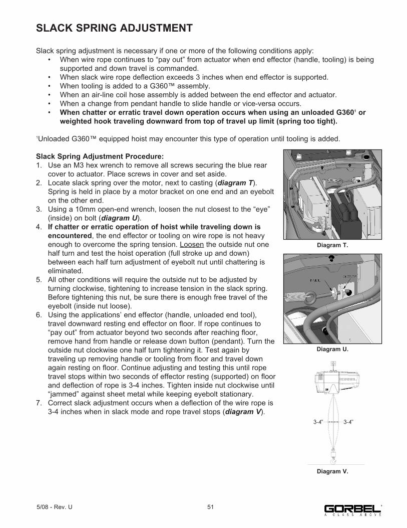
SLACK SPRING ADJUSTMENT
Slack spring adjustment is necessary if one or more of the following conditions apply: • When wire rope continues to “pay out” from actuator when end effector (handle, tooling) is being supported and down travel is commanded. • When slack wire rope deflection exceeds 3 inches when end effector is supported. • When tooling is added to a G360™ assembly. • When an air-line coil hose assembly is added between the end effector and actuator. • When a change from pendant handle to slide handle or vice-versa occurs. • When chatter or erratic travel down operation occurs when using an unloaded G3601 or weighted hook traveling downward from top of travel up limit (spring too tight).
1Unloaded G360™ equipped hoist may encounter this type of operation until tooling is added.
Slack Spring Adjustment Procedure:1. Use an M3 hex wrench to remove all screws securing the blue rear cover to actuator. Place screws in cover and set aside.2. Locate slack spring over the motor, next to casting (diagram T). Spring is held in place by a motor bracket on one end and an eyebolt on the other end.3. Using a 10mm open-end wrench, loosen the nut closest to the “eye” (inside) on bolt (diagram U).4. If chatter or erratic operation of hoist while traveling down is encountered, the end effector or tooling on wire rope is not heavy enough to overcome the spring tension. Loosen the outside nut one half turn and test the hoist operation (full stroke up and down) between each half turn adjustment of eyebolt nut until chattering is eliminated.5. All other conditions will require the outside nut to be adjusted by turning clockwise, tightening to increase tension in the slack spring. Before tightening this nut, be sure there is enough free travel of the eyebolt (inside nut loose).6. Using the applications’ end effector (handle, unloaded end tool), travel downward resting end effector on floor. If rope continues to “pay out” from actuator beyond two seconds after reaching floor, remove hand from handle or release down button (pendant). Turn the outside nut clockwise one half turn tightening it. Test again by traveling up removing handle or tooling from floor and travel down again resting on floor. Continue adjusting and testing this until rope travel stops within two seconds of effector resting (supported) on floor and deflection of rope is 3-4 inches. Tighten inside nut clockwise until “jammed” against sheet metal while keeping eyebolt stationary.7. Correct slack adjustment occurs when a deflection of the wire rope is 3-4 inches when in slack mode and rope travel stops (diagram V).
Diagram T.
Diagram U.
3-4"3-4"
Diagram V.
515/08 - Rev. U

RECOMMENDED SPARE PARTS KITS
Here is a list of the Spare Parts Kits we recommend. We encourage you to have spare parts on hand to limit the potential downtime if your unit experiences issues. To order any of these kits, please contact your authorized Gorbel® distributor.
You will have to know your system specifications such as Capacity, Trolley Saddle Height, Height Under Hook and Span (if applicable to your unit).
Level One Kit contains:One Wire Rope AssemblyOne Coil Cord Assembly
Level Two Kit contains:One Wire Rope AssemblyOne Coil Cord AssemblyOne Hardware Kit
Level Three Kit contains:One Wire Rope AssemblyOne Coil Cord AssemblyOne Hardware KitOne Swivel Kit*
* If your system is equipped with a Suspended Pendant Handle you can use the Level Two Kit because you will not need the Swivel Kit.
• All kits can be used on either G-Forces or Easy Arms regardless of their capacity.
52 5/08 - Rev. U

LIMITED WARRANTYIt is agreed that the equipment purchased hereunder is subject to the following LIMITED warranty and no other. Gorbel Incorporated (“Gorbel”) warrants the manual push-pull Work Station Cranes, Jib Crane, Gantry Crane, and Tether Track® products to be free from defects in material or workmanship for a period of ten years or 20,000 hours use from date of shipment. Gorbel warrants the Motorized Work Station Cranes and Jib Crane products to be free from defects in material orworkmanship for a period of two years or 4,000 hours use from the date of shipment. Gorbel warrants the G-Force® and Easy Arm® products to be free from defects in material or workmanship for a period of one year or 2,000 hours use from the date of shipment. This warranty does not cover Gantry Crane wheels. Thiswarranty shall not cover failure or defective operation caused by operation in excess of recommended capacities, misuses, negligence or accident, and alteration or repair not authorized by Gorbel. No system shall be field modified after manufacture without the written authorization of Gorbel, Inc. Any field modification made to the system without the written authorization of Gorbel, Inc. shall void Gorbel’s warranty obligation. OTHER THAN AS SET FORTH HEREIN, NO OTHER EXPRESS WARRANTIES, AND NO IMPLIED WARRANTIES, ORAL OR WRITTEN, INCLUDING BUT NOT LIMITED TO THE WARRANTIES OF MERCHANTABILITY OR FITNESS FOR A PARTICULAR PURPOSE, ARE MADE BY GORBEL WITH RESPECT TO ITS PRODUCTS AND ALL SUCH WARRANTIES ARE HEREBY SPECIFICALLY DISCLAIMED. GORBEL SHALL NOT BE LIABLE UNDER ANY CIRCUMSTANCES FOR ANY INCIDENTAL, SPECIAL AND/OR CONSEQUENTIAL DAMAGES WHATSOEVER, WHETHER OR NOT FORESEEABLE, INCLUDING BUT NOT LIMITED TO DAMAGES FOR LOST PROFITS AND ALL SUCH INCIDENTAL, SPECIAL AND/OR CONSEQUENTIAL DAMAGES ARE HEREBY ALSO SPECIFICALLY DISCLAIMED. Gorbel’s obligation and Purchaser’s or end user’s sole remedy under this warranty is limited to the replacement or repair of Gorbel’s products at the factory, or at the discretion of Gorbel, at a location designated by Gorbel. Purchaser or end user shall be solely responsible for all freight and transportation costs incurred in connection with any warranty work provided by Gorbel hereunder. Gorbel will not be liable for any loss, injury or damage to persons or property, nor for damages of any kind resulting from failure or defective operation of any materials or equipment furnished hereunder. Components and accessories not manufactured by Gorbel are not included in this warranty. Purchaser’s or end user’s remedy for components and accessories not manufactured by Gorbel is limited to and determined by the terms and conditions of the warranty provided by therespective manufacturers of such components and accessories. A) DISCLAIMER OF IMPLIED WARRANTY OF MERCHANTABILITY Gorbel and Purchaser agree that the implied warranty of merchantability is excluded from this transaction and shall not apply to the goods involved in this transaction. B) DISCLAIMER OF IMPLIED WARRANTY OF FITNESS FOR PARTICULAR PURPOSE Gorbel and Purchaser agree that the implied warranty of fitness for particular purpose is excluded from this transaction and shall not apply to the goods involved in this transaction. C) DISCLAIMER OF EXPRESS WARRANTY Gorbel’s agents, or dealer’s agents, or distributor’s agents may have made oral statements about the machinery and equipment described in this transaction. Such statements do not constitute warranties, and Purchaser agrees not to rely on such statements. Purchaser also agrees that such statements are not part of this transaction. D) DISCLAIMER OF SPECIAL, INCIDENTAL AND CONSEQUENTIAL DAMAGES Gorbel and Purchaser agree that any claim made by Purchaser which is inconsistent with Gorbel’s obligations and the warranty remedies provided with Gorbel’s products, and in particular, special, incidental and consequential damages, are expressly excluded. E) DEALER OR DISTRIBUTOR NOT AN AGENT Gorbel and Purchaser agree that Purchaser has been put on notice that dealer or distributor is not Gorbel’s agent in any respect for any reason. Gorbel and Purchaser also agree that Purchaser has been put on notice that dealer or distributor is not authorized to incur any obligations or to make any representations or warranties on Gorbel’s behalf other than those specifically set forth in Gorbel’s warranty provided in connection with its product. F) MERGER This warranty agreement constitutes a final and complete written expression of all the terms and conditions of this warranty and is a complete and exclusive statement of those terms. G) PAINTING Every crane (excluding components) receives a quality paint job before leaving the factory. Unfortunately, no paint will protect against the abuses received during the transportation process via common carrier. We have included at least one (1) twelve ounce spray can for touchup with each crane ordered (unless special paint was specified). If additional paint is required, contact a Gorbel® Customer Service Representative at 1-800-821-0086 or 1-585-924-6262.
Title and Ownership: Title to the machinery and equipment described in the foregoing proposal shall remain with Gorbel and shall not pass to the Purchaser until the full amount herein agreed to be paid has been fully paid in cash.
Claims and Damages: Unless expressly stated in writing, goods and equipment shall be at Purchaser’s risk on and after Seller’s delivery in good shipping order to the Carrier. Gorbel shall in no event be held responsible for materials furnished or work performed by any person other than it or its authorized representative or agent.
Cancellations: If it becomes necessary for the purchaser to cancel this order wholly or in part, he shall at once so advise Gorbel in writing. Upon receipt of such written notice all work will stop immediately. If the order entails only stock items, a flat restocking charge of 15% of the purchase price will become due and payable by Purchaser to Gorbel. Items purchased specifically for the canceled order shall be charged for in accordance with the cancellation charges of our supplier plus 15% for handling in our factory. The cost of material and/or labor expended in general fabrication for the order shall be charged for on the basis of total costs to Gorbel up to the time of cancellation plus 15%.
Returns: No equipment, materials or parts may be returned to Gorbel without express permission in writing to do so.
Extra Charge Delay: If Purchaser delays or interrupts progress of Seller’s performance, or causes changes to be made, Purchaser agrees to reimburse Gorbel for expense, if any, incident to such delay.
Changes and Alterations: Gorbel reserves the right to make changes in the details of construction of the equipment, as in its judgment, will be in the interest of the Purchaser; will make any changes in or additions to the equipment which may be agreed upon in writing by the Purchaser; and Gorbel is not obligated to make such changes in products previously sold any customer.
Third Party Action: Should Gorbel have to resort to third party action to collect any amount due after thirty (30) days from date of invoice, the Purchaser agrees to pay collection costs, reasonable attorney’s fees, court costs and legal interest.
OSHA Responsibilities: Gorbel agrees to fully cooperate with Purchaser in the design, manufacture or procurement of safety features or devices that comply with OSHA regulations. In the event additional equipment or labor shall be furnished by Gorbel, it will be at prices and standard rates then in effect, or as may be mutually agreed upon at the time of the additional installation.
Equal Employment Opportunity: Gorbel agrees to take affirmative action to ensure equal employment opportunity for all job applicants and employees without regard to race, color, age, religion, sex, national origin, handicap, veteran, or marital status. Gorbel agrees to maintain non-segregated work facilities and comply with rules and regulations of the Secretary of Labor or as otherwise provided by law or Executive Order.
535/08 - Rev. U

Hereby, Gorbel Inc., declares that this material handling equipment is in compliance with the essential requirements and other relevant provisions listed below.
-----------------------------------------------------------------------EMC Directive: 2004/108/ECGeneric Emissions Standard: EN 61000-6-4:2007+A1:2011Product Specific Emissions: EN 55011
Generic Immunity Standard: EN 61000-6-2: 2005Immunity: EN 61000-4-2:2009 Electrostatic Discharge EN 61000-4-2:2009 Radiated Susceptibility
Low Voltage Directive: 98/68/EECStandard: EN 61010 Equipment for Measurement, Control, & Laboratory UseMachinery Directive: 2006/42/ECStandard: EN 60204 Safety of Machinery/Electrical Equipment of Machinery
EN 81-3:2000 “Safety rules for the construction and installation of lifts- Part: 3 Electric and hydraulic service lifts
prEN 81031 “Safety Rules for the construction and installation of lifts- Lifts for the transport of goods only- Part: 31 Accessible goods only lifts
-----------------------------------------------------------------------Manufacturer’s Name: GorbelManufacturer’s Address: 600 Fishers Run P.O. Box 593 Fishers, NY 14453-0593Product: G-ForceModel Number: QAccessories: All
-----------------------------------------------------------------------
Signature: ________________________ Blake Reese Product Development Electrical Engineer Gorbel, Inc. 600 Fishers Run, PO Box 593 Fishers, NY 14453 Phone: 585-924-6262 Fax: 585-924-6273
CE Declaration of Conformity

Hereby, Gorbel Inc., declares that this material handling equipment is in compliance with the essential requirements and other relevant provisions listed below.
-----------------------------------------------------------------------EMC Directive: 2004/108/ECGeneric Emissions Standard: EN 61000-6-4:2007+A1:2011Product Specific Emissions: EN 55011
Generic Immunity Standard: EN 61000-6-2: 2005Immunity: EN 61000-4-2:2009 Electrostatic Discharge EN 61000-4-2:2009 Radiated Susceptibility
Low Voltage Directive: 98/68/EECStandard: EN 61010 Equipment for Measurement, Control, & Laboratory UseMachinery Directive: 2006/42/ECStandard: EN 60204 Safety of Machinery/Electrical Equipment of Machinery
EN 81-3:2000 “Safety rules for the construction and installation of lifts- Part: 3 Electric and hydraulic service lifts
prEN 81031 “Safety Rules for the construction and installation of lifts- Lifts for the transport of goods only- Part: 31 Accessible goods only lifts
-----------------------------------------------------------------------Manufacturer’s Name: GorbelManufacturer’s Address: 600 Fishers Run P.O. Box 593 Fishers, NY 14453-0593Product: G-ForceModel Number: iQAccessories: All
-----------------------------------------------------------------------
Signature: ________________________ Blake Reese Product Development Electrical Engineer Gorbel, Inc. 600 Fishers Run, PO Box 593 Fishers, NY 14453 Phone: 585-924-6262 Fax: 585-924-6273
CE Declaration of Conformity

INSPECTION AND MAINTENANCE SCHEDULE
* Federal, state and local codes may require inspection and maintenance checks more often. Please check the federal, state and local code manuals in your area.
For additional service information, please consult the G-Force® Q and iQ Series Service Manual available from Gorbel or go tohttps://www.gorbel.com/support/warrantyregistration.aspx to register your G-Force® and sign up for our Platinum Service Package.
GORBEL® G-FORCE® INSPECTION AND MAINTENANCE SCHEDULEITEM COMPONENT MAINTENANCE FREQUENCY*
1 Wire RopeLook for any obvious external defects, damage or excessive wear. Check the lower end where it attaches to the handle, swivel assembly or tooling (by others) for signs of damage or excessive wear.
Start of Each Shift
2 Wire RopeExpose as much of the wire rope as possible and wipe it off with a clean dry cloth. Use the jog button to pay out as much wire rope as possible.
Monthly
3 Wire Rope
Maintenance listed in (1) as well as reduction of rope diameter below nominal diameter due to loss of core support, internal or externalcorrosion, or wear of outside wires; severely corroded or broken wires at end connections; or severely corroded, cracked, bent, worn, or improperly applied end connections.
Periodically(to be determined
by qualifiedpersons only)
4 Coil Cord AssemblyLook for any obvious external defects or damage caused by the wire rope of other external causes. Make sure all coil cord clamps are in place.
Start of Each Shift
5 Slack Switch Adjustment
Using the handle, lower the wire rope until it goes slack. There should be no additional movement downward once it is slack. If the wire rope continues to pay out, stop immediately and perform the slack switch adjustment. Check the coil cord and air hose clamps on the wear ring to insure the wear ring is moving freely inside the actuator opening.
Monthly
6 Handle
Check for smooth operation of the handle.• Slide Handle Only - Check operator present sensor for correct operation. Use a gentle puff of compressed air or a soft cloth to clean the sensor. Do not apply any pressure to the lens or do anything that may scratch it. Verify proper handle swivel functionality.• Pendant Handle Only - Check levers to make sure they function smoothly.
Start of Each Shift
7 Handle I/O Connections
Check connections at handle (if equipped). Wipe off any oil or other contamination from either handle at this time. Clean the LCD screen as well.
Monthly
8 Air Hose (if equipped)
Look for any obvious external damage or wear caused by the wire rope or other external causes. Make sure the air hose is secured properly with the correct clamps
Start of Each Shift
9 Load Hook and/or Tooling (by others)
Check that the load hook is secured properly to the handle or swivel. Make sure lock washers are compressed completely and any other associated hardware is secure.
Start of Each Shift
10 G-Force® Assembly Conduct a visual inspection of the entire G-Force® unit. Start of Each Shift
11 Limit SwitchesVerify that the upper and lower limit switches are operating properly. Verify that the slack switch is operating properly. Replace switches immediately if they are faulty.
Start of Each Shift
WARNINGAny changes in rotating effort or unusual noises must be immediatelyidentified and corrected. 600 Fishers Run, P.O. Box 593
Fishers, NY 14453-0593Phone: (800) 821-0086
Fax: (800) 828-1808E-Mail: [email protected]
http://www.gorbel.com
© 2008 Gorbel Inc.All Rights Reserved
54 5/08 - Rev. U
FacebookFacebook.com/gorbelinc
Twittertwitter.com/gorbelinc
linkedin.com/company/gorbel youtube.com/gorbelmarketing gorbel.com/blog