installation, operation & maintenance · prior to powering the unit, verify that the unit has...
TRANSCRIPT

INSTALLATION, OPERATION &
MAINTENANCEFan Filter Units
CRFF-E, CRFF-E-ARS,& CRFF-E-ARSM
ECM MotorsRevision: 02.01.17

Installation, Operation, & Maintenance for CRFF-E Series Page: 2 of 26
Krueger | 1401 N Plano Rd | Richardson, TX 75081 | 972.680.9136 | [email protected] | www.krueger-hvac.com
Table of Contents
Installation ....................................................................................................................................................................4
Unit Control Box ..........................................................................................................................................................5
Universal Control Card Set Up...................................................................................................................................6
Troubleshooting ........................................................................................................................................................11
Infrared Speed Controller .........................................................................................................................................12Pre-filter Cleaning (foam) ..........................................................................................................................................13Service: Removal and Replacement of CRFF-E filters...........................................................................................14
Service: Removal and Replacement of Roomside Replaceable Filters.................................................................15
Service: CRFF-E & CRFF-E-ARS Motor Removal and Installation........................................................................16
Service: CRFF-E-ARSM Motor Removal and Installation.......................................................................................17
Technical Note: TN1004 Changing Motors in the Field..........................................................................................18
Unit Wiring Diagrams.................................................................................................................................................20
Drawing - CRFF-E Filter..............................................................................................................................................24
Critical Operations of the Fan Filter Unit...................................................................................................................3Warnings.......................................................................................................................................................................3
Technical Note: TN1002 Design with VAV Boxes....................................................................................................18
Unit Replacement Parts List.......................................................................................................................................23
Drawing - CRFF-E-ARS & CRFF-E-ARSM Filter........................................................................................................25Testing.........................................................................................................................................................................26

Krueger | 1401 N Plano Rd | Richardson, TX 75081 | 972.680.9136 | [email protected] | www.krueger-hvac.com
Installation, Operation, & Maintenance for CRFF-E Series Page: 3 of 26
Critical Operation Conditions of the CRFF-E, CRFF-E-ARS and CRFF-E-ARSM
1. Touching of the HEPA filter could damage it, voiding the warranty on the filter. The screen is only to protectagainst an accidental ‘touch’ of the filter. Never place a hand or tool on the filter. Never lay the filter face flatdown on a surface always have filter on its side or back to protect from damage
2. Prior to powering the unit, verify that the unit has been plugged into the correct voltage. The serial number labelon the top of the CRFF-E, CRFF-E-ARS and CRFF-E-ARSM unit has the required voltage.
3. For reorder purposes the CRFF-E, CRFF-E-ARS and CRFF-E-ARSM model number, configuration code andserial number should be recorded. This information is located on the product and serial number labels, locatedadjacent to the electrical box. If you cannot locate the FO# please contact Krueger for this information.
Read and Save These InstructionsTo reduce the riskkof fire, electrical shock, or injury to persons, observe the following
1. Installation work and electrical wiring must be done by qualified person(s) in accordance with all applicable codeand standards, including fire-rated construction
2. When cutting or drilling into wall or ceiling, do not damage electrical wiring and other hidden utilities.3. If this unit is to be installed over a tub or shower, it must be marked as appropriate for the application.4. Use this unit only in the manner intended by the manufacturer. If you have any questions, contact the
manufacturer:5. Before servicing or cleaning unit, switch power off at service panel and lock service panel to prevent power from
being switched on accidentally.
!
Note: Units come set in manual mode from the factory. Please review installation requirements and set up with your end user
(See page 7 for complete set up instructions).

Krueger | 1401 N Plano Rd | Richardson, TX 75081 | 972.680.9136 | [email protected] | www.krueger-hvac.com
Installation, Operation, & Maintenance for CRFF-E Series Page: 4 of 26
Installation
The CRFF-E Series Critical Room Fan Filter Units are completely assembled at the factory with the exception of the optional ¼” (0.64 cm)-20 eyebolts, which can be used when hanging the unit from an overhead structure.
1. Carefully remove the unit from the shipping carton and inspect for any damage that may have occurred duringtransportation. (See Figure 1)
Note: When ordering CRFF-ARS and CRFF-ARSM units, the HEPA filters may be shipped separately to beinstalled into units after the fan box has been installed.
Recommendation: Review mode settings at this time as specified for installation (see page 7 for controls).
2. If using rigidly supported grid (usually 2” or wider), raise unit through ceiling and lower onto the gasketed grid. Ifusing a flexible grid (typically supported with wires) the unit must be secured to an overhead structure witheyebolts, s-hooks and chain. Screw the four eyebolts into the nutserts on the lid assembly before lifting into anoverhead position (see Figure 2)
3. Have an electrician wire the unit to the appropriate voltage (115V, 220V, 277V AC), according to the wiringdiagram and all national and local electric codes. All units are equipped with a three position terminal block forfield connection. Verify correct single phase power, before energizing units.
4. Turn on the power using the two position rocker switch (ON/OFF) located on the electrical box. For the CRFF-ARS and CRFF-ARSM units, let the unit fur for a few hours to purge off particulate (if filters are shipped loose)that may adhere to the inside of the unit before installing the filters. Do not run fan at full speed as this may causeoverload condition.
Note: Your fan filter may have been shipped separate. Controls have been shipped separately.
EYEBOLT
FAN FILTERUNIT
FIGURE 1 - UNBOXING FIGURE 2 - HANGAR SUPPORTS

Krueger | 1401 N Plano Rd | Richardson, TX 75081 | 972.680.9136 | [email protected] | www.krueger-hvac.com
Installation, Operation, & Maintenance for CRFF-E Series Page: 5 of 26
ON/OFF Switch - Speed/Airflow Adjustment
All CRFF-E series units are equipped with a two-position rocker switch (ON/OFF), which is located on the side of the electrical box, on top of the unit. Unless otherwise specified, units are furnished with a Universal Control Card to enable adjustment of airflow or set to preferred communication mode.
Note: The CAT5e/RJ45 network ports are non-directional (in or out). Be sure to examine your cabling to insure that there is no cross-over wired cables.
CAT 5eNetwork Cable Connection (RJ45 Connector)
ON/OFF SwitchRPM Test Probe Jack Comm.
Filter Indicator Light Pressure Switch Adjuster Manual Speed Potentiometer
Filter Indicator Light Option
The pressure switch for the filter indicator light option is set at 0.60 in wc from the factory. The set point for the pressure switch can be adjusted between 0.50 in wc and 3.00 in wc by turning the set screw, accessible for the front of the control enclosure. Counterclockwise rotation will increase the set point differential for switching; clockwise rotation will reduce the set point.
The process to adjust this for a specific application is detailed below: 1. Adjust fan to highest setting2. Measure and note initial pressure differential between ceiling plenum and unit plenum (downstream of the fan
and upstream of the filter)3. Restrict discharge airflow incrementally to increase differential pressure until measured value matches filter
loading requirements for the projecta. If no specific filter loading requirements are specified a general recommendation is to use twice the
pressure differential measured in step 24. With the unit discharge blocked, adjust the set point of the pressure switch
a. If the indicator light is illuminated, increase the set point of the pressure switch (CCW rotation) until thelight dims
b. If the indicator light is still dim, slowly decrease the set point of the pressure switch (CW rotation) until thelight illuminates
5. Remove obstruction(s) from the unit discharge6. Adjust fan speed to operational set point

Krueger | 1401 N Plano Rd | Richardson, TX 75081 | 972.680.9136 | [email protected] | www.krueger-hvac.com
Installation, Operation, & Maintenance for CRFF-E Series Page: 6 of 26
Universal Control Card Set Up (ENV1028)
CON4 UNIVERSAL CONTROL CARD - OVERVIEW
Krueger's ENV1028 Universal Control Card provides MODBUS network and analog control capabilities to a Krueger Fan Filter Unit equipped with an electrically commutated motor. Three different control modes provide installation versatility by allowing the FFU to be controlled via MODBUS RTU network, analog 0-10 VDC control signal, or by adjusting the on-board potentiometer. The ENV1028 Universal Control Card is fully compatible with all of Krueger’s plug & play System Control Consoles using MODBUS RTU. Additional details of the controls modes are provided on page 7.
FEATURES+ Networkable Via MODBUS RTU+ 0-10 VDC Analog Control+ Manual Control Via Onboard Potentiometer+ Simple Connections
- RJ45 For Networking Connection- Screw Terminals For Analog Control- Test Probe Jacks For DC mV Signal Output Of The Following:
- RPM- Motor Control Set Point
+ LED Diagnostics- Support for external LED (10mA) remote status notification via
2 Pin MTA connector- On-board green LED for Board Status notification- On-board red LED for Network Traffic
+ Powered from Network or Local Supply
COMMON INCOMING POWER 24VAC
LED CONNECTOR
CONTROL HARNESSCONNECTOR
CONTROLDIP SWITCH
ADDRESSING DIP SWITCH
ANALOG INPUT “COM”
ANALOG INPUT “SIGNAL”
RPM TEST PROBE JACK “COM”RPM TEST PROBE JACK “SIGNAL”
GREEN LED FOR SYSTEM/RPM STATUS
RED LED FOR NET ACTIVITY
DUAL RJ-45 JACKSFOR CAT5 CABLE
MANUAL SPEED POT
FIGURE 7: UNIVERSAL CARD OVERVIEW

Krueger | 1401 N Plano Rd | Richardson, TX 75081 | 972.680.9136 | [email protected] | www.krueger-hvac.com
Installation, Operation, & Maintenance for CRFF-E Series Page: 7 of 26
Control Modes
The ENV1028 operates in one of three selectable modes. The Mode is selected using the control DIP switch; MANUAL control (on-board potentiometer), ANALOG control (Remote 0-10 VDC), NETWORK control (MODBUS RTU). The ENV1028 is shipped from the factory in NETWORK control mode.
Manual Control ModeIn Manual control mode, the motor speed is set using the onboard potentiometer. Onboard potentiometer rotation is CW to increase the motor output.
Analog Control ModeIn ANALOG control mode, the motor output is set using an external 0-10 VDC demand signal.
Network Control ModeIn NETWORK control mode, the motor output is set using MODBUS Register 2. Motor output is specified as a value from 0 to 100 representing a percentage of motor torque output. Each ENV1028 in a MODBUS network must be set to a unique address. The address value is set in binary using the eight DIP switches of switch band (S2). A maximum of 200 ENV1028 devices is recommended per local area network (LAN).
NetworkkControl Mode (cont)If a Krueger ACC Control Console is the MODBUS master, then addresses should be assigned within the address range supported by the Control Console. Address zero should not be used as it is reserved for global commands. Address switch settings are only checked by the ENV1028 at power-up. Power must be cycled (OFF/ON) before any changes take effect.
Registers relevant to this mode:
1
ON ADE02 21 3 4 5 6 7 8ON
2
1
ON ADE02 21 3 4 5 6 7 8ON
2
Manual Mode = 1 OFF 2 OFF
Analog Mode = 1 ON 2 OFF
Note: Network mode can be configured using either DIP switch setting shown above. DIP switch pictorials are for reference and may be labeled differently by the manufacturer.
1
ON ADE02 21 3 4 5 6 7 8ON
2
Network Mode = 1 OFF 2 ON
1
ON ADE02 21 3 4 5 6 7 8ON
2
Network Mode = 1 ON 2 ON
• Register 1 “Start/Stop” (R/W)– To enable motor, write a value of 1; To disable
motor, write a value of 0• Register 2 “Motor Set Speed” (R/W)– Motor Target speed value. Values may be written
from 0 to 100• Register 6 “RPM” (R)– Motor RPM. Read from the motor
• Register 12 “Actual Motor Speed Instruction” (R)– Speed control signal applied to the motor by the
ENV1028. (R/W) = Read/Write, (R) = Read Only

Installation, Operation, & Maintenance for CRFF-E Series Page: 8 of 26
Krueger | 1401 N Plano Rd | Richardson, TX 75081 | 972.680.9136 | [email protected] | www.krueger-hvac.com
Control Modes (continued)
Example of binary S2 switch settings
5 61 2 3 4 87
ON DIP
11 2 3 4 5 6 7 8
ON DIP
111 2 43 5 6 87
ON DIP
21
3 1 2 4 5 6 7 8
ON DIP
21 2 3 4 5 6 7 8
ON DIP
1221 3 4 5 6 7 8
ON DIP
22
1 2 3 4 5 6 7 8
ON DIP
31 2 3 4 5 6 7 8
ON DIP
131 2 3 4 5 6 7 8
ON DIP
23

Installation, Operation, & Maintenance for CRFF-E Series Page: 9 of 26
Krueger | 1401 N Plano Rd | Richardson, TX 75081 | 972.680.9136 | [email protected] | www.krueger-hvac.com
Electrical Specification
Control and Interface Signals
External Speed 0-10V Input• Input impedance 20k0hms.• MIN ON-to-OFF threshold: 190mV*• MAX OFF-to-ON threshold: 240mV*• ON (-215mV) to 9.89V linearly scales 1 to 99% speed.• 9.89V or more deadbands to 100% speed.
External LED Output• 10mA regulated.• LED forward voltages up to 5V.
RPM Signal• Signal Value: mVDC = RPM• Ex: 900mV = 900RPM• RPM Output Range: - 0, 5 to 2000 RPM (0, 5mV to 2000 mV DC)• RPM Output Resolution: 5RPM (zero, 400 steps from 5 to 2000 RPM inclusive)
Specificatio Min Typical Max UnitsInput Voltage 22 24 42 VAC
Supply Frequency 50 50 / 60 60 Hz
Input Power Consumption n/a n/a 0.5 VA
Ambient Operating Temperature 0 25 50 C
RJ45 Network Cable Connections1 2 3 4 5 6 7 8
Bus Power Pass Through 0V (GND)
RS-4850V (GND) Bus Power
Pass Through+ NC NC -
Net LED Status DefinitioGreen LED OFF Power lost or no communications.
LED Flickering Network data traffic in progress
Green LED ON A/B network cables are swapped.
RED NETWORK LED GREEN STATUS LED
FIGURE 9: LED LIGHT LOCATIONS
Test Probe Jack PointsThe test probe jacks may be used to measure the motor rpm or the PWM signal that is being output to the motor.
• In Manual or Analog Control Mode with an Addresssetting of 1 or greater, the test probe jacks output0-2000 mVDC representing motor RPM. By changingthe address DIP switches to 0, the test probe jacks willoutput 0-1000 mVDC representing 0-100% demandsignal to the motor. The address may be changedwithout interrupting power to the control card.
• In Network Control Mode, 0-2000 mVDC alwaysrepresents RPM.
LED Indicators• Onboard Status LED:
The Onboard Status LED is software controlledby the unit microcontroller. The Status LED is solidON when RPM reported by the motor is greater thanzero and OFF when RPM reported by the motor iszero.
• External Status LED:Support for an external Status LED (10mA current-controlled driver), via a 2-pin MTA connector, forremote system status notification. The external StatusLED operates in the same manner as the OnboardStatus LED.
• Onboard Net LED:The Onboard Net LED is driven directly by the receivedata signal. The NET LED shows all network traffic ona 2-wire network. The NET LED is intended toconfirm low-level network connectivity,independent of microcontroller or firmwarefunctionality. If A/B network wires are swapped, theNET LED will be normally on, providing quickdiagnostics of this common condition.

Installation, Operation, & Maintenance for CRFF-E Series Page: 10 of 26
Krueger | 1401 N Plano Rd | Richardson, TX 75081 | 972.680.9136 | [email protected] | www.krueger-hvac.com
Communication Specification
Overview• MODBUS RTU protocol over RS485 (serial).• 9600 baud rate, word length is 8, parity is none(n), stop bits=1.• 255 unique address values selectable by DIP switch settings. (Recommended network node capacity 200 nodes.)• Slew rate limited transceivers for improved network performance.• Do not use crossover cables. This may damage the control card or render it non-operational.
To reset non-volatile registers to factory default values, write 170 (AA hex) to Register 14, then cycle power.
Note: Register 24 may be read in network mode to determine the value of 0-10VDC signal that may be connected. For example, a pressure transducer may be conected to indicate unit static pressure
MODBUS REGISTER SUMMARY TABLE
12
6
9101214
1
1
RUN/STOPDEMANDSPEED
STATUSDEFAULT SPEEDCURRENT SPEED
DEFAULT RUN/STOP
RWRW
RW
RW
R
R
R
0-100
0-100
0-100
0,1
0,1
0,5-2000
see detail
%RPM
50-
-
RAMRAM
LIVE
LIVE
LIVEEEPROM
EEPROM
power up from REG 14
power up from REG 10
applies to network only
applies in network mode only
Register Name R/W Values & Defaults Units Origin Comments
24
7 0-1000 LIVE-ANA1 Onboard Pot 0-1000=0-100%
0-1000 LIVE-ANA2 0-10V input 0-1000=0-10VDC
R
R

Krueger | 1401 N Plano Rd | Richardson, TX 75081 | 972.680.9136 | [email protected] | www.krueger-hvac.com
Installation, Operation, & Maintenance for CRFF-E Series Page: 11 of 26
1. Check pre-filter media; replace or clean asnecessary.
2. Adjust visual speed control for higher blower output.3. Check power supply for proper voltage, amperage
and distribution frequency.4. Replace HEPA filter if the air velocity remains low.
1. Ensure that no large obstructions are upstream ofairflow pattern
2. Determine that no other air-moving devices areoperating in or around clean room which disruptroom’s airflow pattern
3. Check air velocity and if low, conduct the “Low AirVelocity” procedure outlined above.
4. Conduct smoke and photometer test on HEPA filte .Seal or replace HEPA filter as necessar .
High Air Velocity
1. Adjust visual speed control for lower blower output.
Non-Laminar Flow and/or Excessive Contamination
Warranty
Please reference the Krueger website for Warranty information located in the Terms and Conditions of Sales document or click on the following link,
http://www.krueger-hvac.com/pdf/terms.pdf
Troubleshooting
Mode Choice
Verify mode setting choice to DIP switch S1 (Control Mode), which is manual mode and then retry.
Motor Issues in Manual Mode
(If you are in a network or analog mode, contact your controls contractor for troubleshooting assistance; if you continue to need assistance, contact the factory.)
Unit is Not Adjustable
Verify that rotation of the knob does not change the RPM or Flow Index display on the unit. If rotating does nothing, remove the electrical box cover and remove the 4-pin connector from the Visual Speed control and installin 180 degrees rotated. Again adjust the knob. The 4 pinconnector is on the 1/8” white conductor.
Low Air Velocity
CRFF Series Replacement Parts
Replacement parts are available through your authorized Krueger representative.
Please visit the Krueger website at www.krueger-hvac. com to find your local Krueger representative

Infrared Speed Control (Optional)
The Flow-Set is a handheld infrared remote control configured to adjust the Krueger CRFF-E and CRFF-E-ARS units.
An EVO/ECM-IRC control sends the ECM motors a FLOW INDEX and a GO signal. The motor sends back a status signal that is connected to a red lamp. The control includes an infrared remote receiver.
The Flow-Set handheld remote sends infrared remote commands to the EVO/ECM-IRC control, allowing remote adjustment of the ECM motor. Using the Flow-Set, you can turn the motor ON/OFF, adjust the flow index from 1-100 and read the current settings.
Point the Flow-Set at the Flow-Set target (red lamp if the motor is on) on the equipment. Operate the ON/OFF button or any of the four ↑↓ buttons. The green lamp near the Flow-Set target lights, indicating you are in an adjustment session. Continue to operate the on/off button or any of the four ↑↓ buttons to achieve the desired settings.
Press the Enter button to save your new settings and exit the adjustment session. Press the Clear button to delete your new settings, revert to the ECM settings and exit the adjustment session. If you enter an adjustment session and do not make any adjustments for 15 minutes, the adjustment session automatically clears.
Use the Clear button to read the current settings. Point the Flow-Set at the Flow-Set target and press the Clear button. A green lamp begins to flash indicating the signal was received. The flash sequence indicates the current flow index. The sequence occurs in two sets. The tens (1st) set uses long flashes to indicate the tens digit. The units (2nd) set uses short flashes to indicate the unit’s digit. An extra long flash in the tens set or the units set indicates the value of the corresponding digit is zero.
• A flow index of 24 flashes two longs, then 4 short• A flow index of 89 flashes 8 longs, then 9 short• A flow index of 30 flashes 3 longs, then an extra lon• A flow index of 04 flashes an extra long, then 4 shor• A flow index of 100 flashes 10 longs, then an extra lon
Use the ON/OFF button to turn the motor on or off. Point the Flow-Set at the Flow-Set target on the equipment and press the ON/OFF button. If you press Enter while the mo-tor is off, the motor stays off, even through a power ON/OFF cycle.
Adjust the flow index using the ↑↓ buttons. The ↑↓ button pair on the left adjusts the index ↑↓ 10. The ↑↓ button pair on the right adjusts the flow index ↑↓ 1. Using the ↑↓ 10 pair, you can quickly move the index up and down. Using the ↑↓ 1 pair, you can precisely set the index to achieve the desired flo . During an adjustment session, the green lamp blinks each time you make a valid entry. If the flow index is already 100, and you try to increase the flow index, the green lamp does not blink, and the increase does not occur. If the flow index is at 91 and you press the ↑10 buttons, the green lamp does not blink and the increase does not occur because your entry would take the index above 100. When the flow index is greater than 90, use the ↑1 button to increase the index. The ↓1 and ↓10 keys respond in a like manner when you try to set the flow index below 1. (Zero is not a valid flow index)
Batteries
Two AA batteries power the EVO/IRC-Masters. Remove the sliding door on the back of the unit to expose the battery compartment. Remove the old batteries. Insert the new batteries in the position indicated by the battery pictures molded into the bottom of the battery compartment. The battery spring clips are difficult, so you may need to use a small screwdriver to “shoehorn” the batteries into place.
For maximum battery life, store the EVO/IRC-Masters so the buttons are not pressed. While current drain is minimum when the unit is not sending infrared signals, some battery current is drawn to sense the pressed key.
Installation, Operation, & Maintenance for CRFF-E Series Page: 12 of 26
Krueger | 1401 N Plano Rd | Richardson, TX 75081 | 972.680.9136 | [email protected] | www.krueger-hvac.com
INFRARED REMOTE

Installation, Operation, & Maintenance for CRFF-E Series Page: 13 of 26
Krueger | 1401 N Plano Rd | Richardson, TX 75081 | 972.680.9136 | [email protected] | www.krueger-hvac.com
Cleaning the CRFF-E Prefilter
Disconnect the unit from the electrical power source before attempting any service.
Tools Required: NoneFilter Dimensions: 23.25”x16”
1.
2.3.
4.
To gain access to the prefilte , remove the ceiling panel next to the unit, if applicable.Switch the ON/OFF switch to the OFF position. Remove the prefilter from the snap-in frame(See Figure 1)Clean the prefilter by hand washing in water with mild detergent or by using a vacuum cleaner. Allow prefilter to dry completely before replacing
5. Reassemble by reversing the above steps.
Note: To keep the filter in top operating condition, washing the foam prefilter is recommended every three to six months.
!
PREFILTER SURFACE ON TOP SIDE
SUPPORT SCREEN ON BOTTOM SIDE
FIGURE 1: BASIC UNIT ASSEMBLY
ON/OFF SWITCH

Krueger | 1401 N Plano Rd | Richardson, TX 75081 | 972.680.9136 | [email protected] | www.krueger-hvac.com
Installation, Operation, & Maintenance for CRFF-E Series Page: 14 of 26
Removal and Replacement of the HEPA/ULPA Filter (CRFF-E Type Units)
Disconnect the unit from the electrical power source before attempting any service. The standard filter is protected with an expanded metal face screen. This is never to be used to handle the filter. It is only for protection against an accidental touch of the filter. Only handle the filter by the frame
Tools Required: Phillips Head Driver, Battery Operated Drill with 5/32 drill bit, Rivet Hand Tool, 5/32 aluminum grip range .126-.187
1. Remove unit from ceiling.2. Remove the 10 screws holding the HEPA/ULPA filter to the lid assembly.3. Lift the lid assembly off the HEPA/ULPA filter. (See Figure 1) Remove filter deflectors using 5/32 drill bit. Keep filter
deflectors to install in new filter. Discard the used filter as per requirements of the applicableregulations. Carefully install the filter deflectors into the new filter using the 5/32 rivets. Do not touch or place thefilter deflectors on the HEPA/ULPA media pack. This could cause tears in the filter pack.
4. Before replacing with the new filter, carefully inspect the new filter for any visible damage. Also inspect the gasketand the T-Bar to insure a tight seal. Replace if necessary.
5. To replace a filter, raise the filter and rotate into position in the ceiling grid (with power off), then lower the plenumhousing into place. Reconnect wiring and hardware from previous steps that havebeen removed.
6. Restore power and verify proper operation of CRFF-E.
!
Figure 1: Standard Filter Change
On/Off Switch
Lid Assembly
#8 Screws (10x)
Ø5/32 Rivet (6x)
HEPA/ULPA filter
Filter Deflector
Electrical Knock-Out

Installation, Operation, & Maintenance for CRFF-E Series Page: 15 of 26
Krueger | 1401 N Plano Rd | Richardson, TX 75081 | 972.680.9136 | [email protected] | www.krueger-hvac.com
Removal and Installation of the Access Room Side Gel Seal Filter – Extruded Aluminum Housing (CRFF-E-ARS Type Units)
Disconnect the unit from the electrical power source before attempting any service.The ARS filter is protected with an expanded metal face screen. This is never to be used to handle the filter. It is only for protection against an accidental touch of the filter. Only handle the filter by the frame
Tools Required: Phillips Head Driver, Battery Operated Drill, 3/16” hex head ball driver (2ea) Manpower Required: 2
1. With the power off, remove the diffuser screen by removing the 6 each 10-32x1/2 screws, then carefully place ina safe location.
2. Loosen the six 1/4x12 socket head screws far enough to rotate the eight filter clips 90°. The filter may be looseenough to drop during this operation. If not, slowly pull the filter away from the knife-edge seal, taking care not totouch the filter face during this operation. It is important to pull the filter slowly away from the seal, so that the gelremains in the filter gel track.
3. Carefully clean plenum assembly knife edge surface of residual gel material.4. Inspect filter for visible damage, if damaged set aside for replacement or repair.5. Inspect the gel seal, if reinstalling the removed filter. Determine if the gel has lost its ability to seal (i.e. the gel
should reform to cover the track without voids or openings), if so repair the gel material or consider replacementof filter.
6. Place the filter evenly against the filter-sealing surface of the unit. Reposition filter clips and screws. The clipsshould be rotated and angled into place. It is recommended that four workers work on each corner of the filtersimultaneously, holding the filter seated into the track. Hand tighten clips from opposite corners evenly until allclamps are tightened.
7. Reinstall diffuser screen by hand-tightening the screws.8. Determine if recertification or testing of replacement is required.9. Restore power to FFU and verify proper operation of FFU.
!
RSR/E Sheet Metal Filter Replacement
Filter
Filter Clip
¼ -20 Cap
Screw
10-32 PHP
Screws
Knife- Edge Seal
Gel Track
Diffuser Screen
CRFF-E-ARS & CRFF-E-ARSM Filter Change
Fan Filter Unit
Filter
2-Piece WeldedPlenum Housing
Filter Clip andScrew (typ 6)
Diffuser ScreenScrews (typ 6)

Krueger | 1401 N Plano Rd | Richardson, TX 75081 | 972.680.9136 | [email protected] | www.krueger-hvac.com
Installation, Operation, & Maintenance for CRFF-E Series Page: 16 of 26
Removal and Installation of the Motor (CRFF-E and CRFF-E-ARS Models)
Disconnect the unit from the electrical power source before attempting any service.Electrical service should be performed by licensed electricians or authorized KRUEGER service technicians.
Tools Required: Phillips Head Driver, Battery Operated Drill, (2) 8" adjustable wrenches, 3/8” (10mm) Hex Head Wrench, Pliers, and #2 Screwdriver
1. To gain access to the motor, remove the ceiling panel next to the unit, if applicable.2. Switch the ON-OFF switch to the off position.3. Remove the prefilter o f the prefilter frame. (See Figure 4)4. Loosen the electrical box cover screws (2), and slide/lift off cover. (See Figure 4)5. Make note of all wire locations for re-installation later.6. Disconnect 5-pin and 16-pin wire harnesses from the electrical box housing and remove tubing for test port, if
installed.7. Remove the eight mounting screws to free the motor/blower assembly from the lid assembly. If using power
drivers, set the unit to a low torque setting to avoid stripping the sheet metal screws. Carefully remove housingassembly, paying attention to wire routing. (See Figure 4)
8. Using an adjustable wrench loosen the two set screws that attach the blower wheel to the motor shaft.9. Mark the location of the motor support bracket (belly band), then loosen the bolt just enough to allow the motor
support bracket to slid off the motor.10. Using the removed motor, mark the new motor with the location of the motor support bracket.11. Replace with the new motor and reassemble by reversing the above steps 1-8. Set the spacing at 0.25” (6.35
mm) clearance between the blower and the upper motor plate/prefilter frame. This will give a 0.11” overlapbetween the venturi ring and the blower.
!
FIGURE 4: MOTOR REPLACEMENT
PREFILTER
ON/OFF SWITCH
VENTURI RING
MOTOR
BLOWER WHEEL
Power Entrance

Installation, Operation, & Maintenance for CRFF-E Series Page: 17 of 26
Krueger | 1401 N Plano Rd | Richardson, TX 75081 | 972.680.9136 | [email protected] | www.krueger-hvac.com
Removal and Installation of the CRFF-E-ARSM with Access Room Side Motor
Disconnect the unit from the electrical power source before attempting any service. Electrical service should be performed by licensed electricians or authorized KRUEGER service technicians.
1. To gain access to the motor, remove the gel seal filter (See Figure 5)2. Prior to removing motor/blower assembly, remove blower wheel to expose motor connectors on motor. Using an
adjustable wrench loosen the two set screws that attach the blower wheel to the motor shaft. Disconnect the twobrown wires from the capacitor, using a pair of pliers. Disconnect 5-pin and 16-pin wire harnesses from theelectrical box housing and remove the tubing for test port, if installed.
3. While supporting the motor/blower assembly from below, remove the six machine screws that secure the venturiring to the bottom face of the lid.
4. Using a 5/32” (0.40 cm) Allen wrench, remove the blower wheel from the motor shaft. Remove motor from theventuri ring by removing the three # 10 bolts.
5. Before removal of the motor mount bracket, measure the precise location of the bracket on the motor. Removethe bracket.
6. Replace with the new motor and reassemble by reversing the above steps. Set the location of the motor mountbracket as measured (see above Step 6). Set the spacing at 0.25” (6.35 mm) clearance between the blower andthe upper motor plate/prefilter frame creating a 0.11” (2.80 mm) overlap between the wheel and the venturi ring.When reinstalling the assembly, align the plate to insure that the leads will reach the electrical box.
GROMMET
MACHINE SCREWAND WASHER
WELLNUT
VENTURIRING
BLOWERWHEEL
MOTOR
!
FIGURE 5: CRFF-ARSM WITH ROOM SIDE ACCESSIBLE MOTOR REPLACEMENT
SCREEN
GEL SEAL FILTER
BAFFLEASSEMBLY
MOTOR / BLOWERASSEMBLY
ELECTRICAL CONNECTORS
LOCATED IN THE INNER
PREFILTER WALL
PLENUM
Tools Required: 3/16""Ball Driver, Phillips screw bit, Head Driver, Battery Operated Drill, (2) 8” adjustable wrenches, 3/8" (10 mm) hex head wrench, #2 standard screwdriver, and pliers.
Installation, Operation, & Maintenance for CRFF-E Series Page: 18 of 26
Krueger | 1401 N Plano Rd | Richardson, TX 75081 | 972.680.9136 | [email protected] | www.krueger-hvac.com
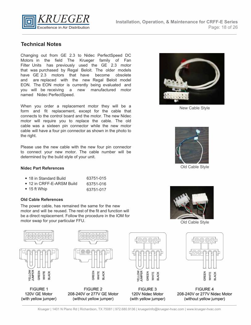
Old Cable Style
Old Cable Style
New Cable Style
Technical Notes
Changing out from GE 2.3 to Nidec PerfectSpeed DC Motors in the field The Krueger family of Fan Filter Units has previously used the GE 2.3 motor that was purchased by Regal Beloit. The older models have GE 2.3 motors that have become obsolete and are replaced with the new Regal Beloit model EON. The EON motor is currently being evaluated and you will be receiving a new manufactured motor named Nidec PerfectSpeed.
When you order a replacement motor they will be a form and fit replacement, except for the cable that connects to the control board and the motor. The new Nidec motor will require you to replace the cable. The old cable was a sixteen pin connector while the new motor cable will have a four pin connector as shown in the photo to the right.
Please use the new cable with the new four pin connector to connect your new motor. The cable number will be determined by the build style of your unit.
Nidec Part References
63751-01563751-016
• 18 in Standard Build• 12 in CRFF-E-ARSM Build• 15 ft Whip 63751-017
Old Cable ReferencesThe power cable, has remained the same for the new motor and will be reused. The rest of the fit and function will be a direct replacement. Follow the procedure in the IOM for motor swap for your particular FFU.

Installation, Operation, & Maintenance for CRFF-E Series Page: 19 of 26
Krueger | 1401 N Plano Rd | Richardson, TX 75081 | 972.680.9136 | [email protected] | www.krueger-hvac.com
Technical Notes (continued)
Designs with Duct Collar, VAV or constant air box and fan coilsFor applications requiring powered fan filter units and a ducted connection our recommendation would be to use CRFF, CRFF-ARS, or CRFF-ARSM units equipped with PSC motors.
CautionCRFF-E, CRFF-E-ARS, and CRFF-E-ARSM units are not recommend for use with ducted systems, and cannot operate with inlet static pressure exceeding 0.30 in wg.
For applications when you use a VAV box or Constant Airflow Terminal, Duct Collars or Fan coils. The design engineer must advise the contractor or air balancer that the air supply needs to be balanced. If you do not balance the air supply properly you have the potential to starve or over feed the fan with air causing the motor to stall which can damage the fan motor. This also can be minimized by notifying Krueger beforehand for assistance. The ECM motors used in the CRFF-E, CRFF-E-ARS, and CRFF-E-ARSM designs are a Microprocessor controlled motor and are designed to maintain a constant air volume. When two controllers are compensating the air volume at the same time, the motor microprocessor is unable to stabilize the airflow and will shut itself down if it cannot find a stable operating point.
In addition to properly balancing the airflow to the Fan, you shouldprepare a sequence of operations turning on FFU’s prior to energizing the Air Handler to prevent potential backward rotation of the blower wheel which can prevent motor rotating in the proper direction and will reduce airflow and cause eventual shutdown. The drive components inside the ECM motors are self-testing and sized for the motor being used inside the unit they can’t compete with the airflows from a duct blower motor.

Installation, Operation, & Maintenance for CRFF-E Series Page: 20 of 26
Krueger | 1401 N Plano Rd | Richardson, TX 75081 | 972.680.9136 | [email protected] | www.krueger-hvac.com
Universal Card Wiring Diagram
4 pin Control Cable
5 pin Power Cable
4 Pin MTA Motor Connector
Remote Run Indicator LED
Wiring Diagrams

Installation, Operation, & Maintenance for CRFF-E Series Page: 21 of 26
Krueger | 1401 N Plano Rd | Richardson, TX 75081 | 972.680.9136 | [email protected] | www.krueger-hvac.com
Wiring Diagrams (continued)
Universal Card Wiring Diagram w/ Continous Filter Monitoring
4 pin Control Cable
5 pin Power Cable
4 Pin MTA Motor Connector
Remote Run Indicator LED
Note: Register 24 may be read in network mode to determine the value of 0-10VDC signal from the pressure
transducer connected to indicate unit interal static pressure.
RE
D
PressureTransducer

Installation, Operation, & Maintenance for CRFF-E Series Page: 22 of 26
Krueger | 1401 N Plano Rd | Richardson, TX 75081 | 972.680.9136 | [email protected] | www.krueger-hvac.com
Wiring Diagrams (continued)
Infrared Speed Control
Remote Mounted Visual Control Unit

Installation, Operation, & Maintenance for CRFF-E Series Page: 23 of 26
Krueger | 1401 N Plano Rd | Richardson, TX 75081 | 972.680.9136 | [email protected] | www.krueger-hvac.com
Replacement Parts List
Model Size/Voltage Description Part NumberN/A Disconnect Switch 63739-002N/A Pre-filter (foam) 62981-001N/A Deflector - Filter 38532-001N/A Gasket, Neop .125x.5 62968N/A Grommet 5/8 Id 1 1/8 Od 63388N/A Choke 3.0 Amps 63720
120V 63677208V-240V 63666
277V 63665N/A Blower Wheel 63270N/A Ventiri Ring 62964N/A Universal Control Card (CRFF-E, CRFF-E-ARS, CRFF-E-ARSM) 265888N/A Visual Speed Control Card (CRFF-E, CRFF-E-ARS, CRFF-E-ARSM) 63951-002N/A IR Sensor Harness 63759-001N/A IR Sensor without Harness 63758
2x2 - 120V S266587-0052x2 - 208V-240V S266587-005
2x2 - 277V S266587-0064x2 - 120V S266587-001
4x2 - 208V-240V S266587-0014x2 - 277V S266587-002
2x2 - 120V S266587-0152x2 - 208V-240V S266587-015
2x2 - 277V S266587-0164x2 - 120V S266587-011
4x2 - 208V-240V S266587-0114x2 - 277V S266587-012
CRFF-E-ARSM
Transformer 24V
CR
FF-E
CR
FF-E-A
RS
CR
FF-E-A
RS
MCRFF-E
CRFF-E-ARS
ECM Motor Assembly (CRFF-E & CRFF-E-ARS)
ECM Motor Assembly (CRFF-E & CRFF-E-ARS)
ECM Motor Assembly (CRFF-E-ARSM)
ECM Motor Assembly (CRFF-E-ARSM)

Installation, Operation, & Maintenance for CRFF-E Series Page: 24 of 26
Krueger | 1401 N Plano Rd | Richardson, TX 75081 | 972.680.9136 | [email protected] | www.krueger-hvac.com
CRFF-E Filter Drawing

Installation, Operation, & Maintenance for CRFF-E Series Page: 25 of 26
Krueger | 1401 N Plano Rd | Richardson, TX 75081 | 972.680.9136 | [email protected] | www.krueger-hvac.com
CRFF-E-ARS and CRFF-E-ARSM Filter Drawing

Krueger | 1401 N Plano Rd | Richardson, TX 75081 | 972.680.9136 | [email protected] | www.krueger-hvac.com
Installation, Operation, & Maintenance for CRFF-E Series Page: 26 of 26
Testing
Each CRFF-E series unit is thoroughly tested at the factory before shipment. However, because of the “rigors” of shipping, Krueger encourages its re-test after installation. Additional, for large installations it is recommended to bench test 5% of the units prior to installation.
Krueger recommends that the customer contact an independent organization, with technicians trained and experienced in performance evaluation and maintenance of clean air equipment.
Some of the testing procedures performed on the CRFF-E series units include PSL challenge of HEPA/ULPA filtersto assure specified performance, along with air velocity measurement and adjustment tests. No DOP is used on CRFF-E series filters, unless requested
Recommended TestingAll units that are airflow tested at Krueger are tested using a Shortridge Airdata Multimeter 800 series with a Velgrid head. The recommended method of reading is to place one corner of the Velgrid head 1-1/4” from the corner of the filter face and then take four reading evenly spaced along the four foot side, and then repeat these reads for the other long side. This gives a total of eight reading to test the unit. All advertised data is based on using the Velgrid with eight readings (128 velocity points). Krueger recognized using eight reading during a cleanroom start-up may be time consuming and recommends using three Velgrid readings taken on a diagonal, as shown below.
FIGURE 17: RECOMMENDED TESTING – 8 POSITION READINGS WITH A VELGRID
FIGURE 18: FACTORY APPROVED TESTING – 3 READINGS WITH A VELGRID
