installation operation maintenance … i.l. 41-771a installation • operation • maintenance...
TRANSCRIPT

Westinghouse I.L. 41-771A
INSTALLATION • OPERATION • MAINTENANCE
INSTRUCTIONS
TYPE ITH RELAY
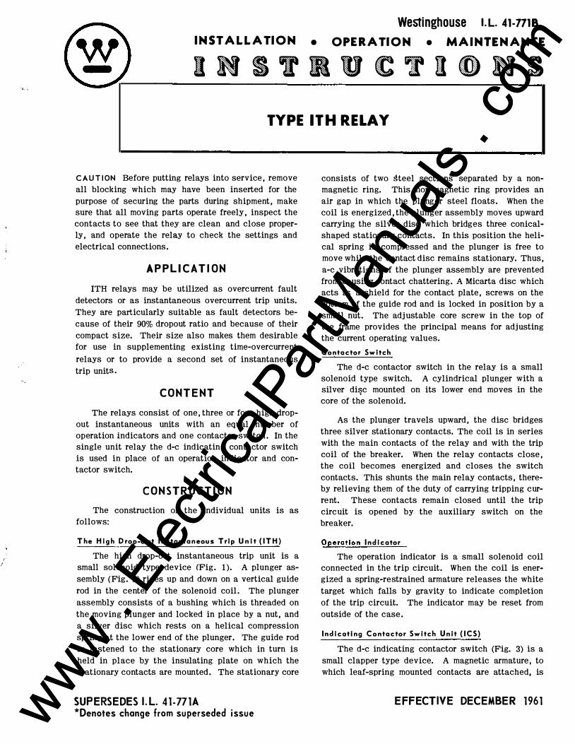
C AUT I 0 N Before putting relays into service, remove all blocking which may have been inserted for the purpose of securing the parts during shipment, make sure that all moving parts operate freely, inspect the contacts to see that they are clean and close properly , and operate the relay to check the settings and electrical connections.
APPLICAT I ON
ITH relays may be utilized as overcurrent fault detectors or as instantaneous overcurrent trip units. They are particularly suitable as fault detectors because of their 90% dropout ratio and because of their compact size. Their size also makes them desirable for use in supplementing existing time-overcurrent relays or to provide a second set of instantaneous trip units.
CON T E N T
The relays consist of one, three or four high dropout instantaneous units with an equal number of operation indicators and one contactor switch. In the single unit relay the d-e indicating contactor switch is used in place of an operation indicator and contactor switch.
CON ST RU CT I ON
The construction of the individual units is as follows:
The High Drop-Out I nstantaneous Tr i p Unit ( ITH)
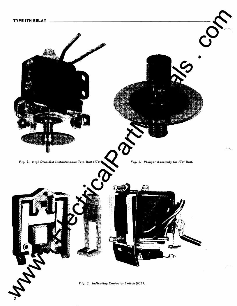
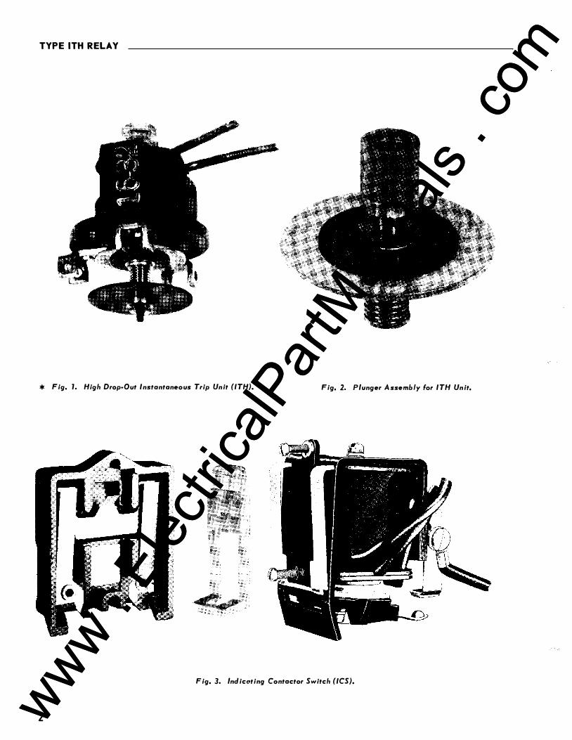
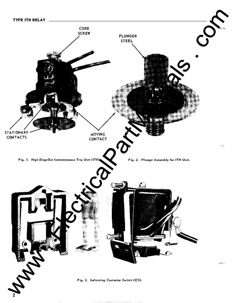
The high drop-out instantaneous trip unit is a small solenoid type device (Fig. 1). A plunger assembly (Fig. 2) rides up and down on a vertical guide rod in the center of the solenoid coil. The plunger assembly consists of a bushing which is threaded on the moving plunger and locked in place by a nut , and a silver disc which rests on a helical compression spring at the lower end of the plunger. The guide rod is fastened to the stationary core which in turn is held in place by the insulating plate on which the stationary contacts are mounted. The stationary core
SUPERSEDES I .L. 41-771
* Denotes change from susperseded issue
consists of two �teel sections separated by a nonmagnetic ring. This non-magnetic ring provides an air gap in which the plunger steel floats. When the coil is energized, the plunger assembly moves upward carrying the silver disc which bridges three conicalshaped stationary contacts. In this position the helical spring is compressed and the plunger is free to move while the contact disc remains stationary. Thus, a-c vibrations of the plunger assembly are prevented from causing contact chattering. A Micarta disc which acts as a shield for the contact plate, screws on the bottom of the guide rod and is locked in position by a small nut. The adjustable core screw in the top of the frame provides the principal means for adjusting the current operating values.
Contoctor Switch
The d-e contactor switch in the relay is a small solenoid type switch. A cylindrical plunger with a silver di�c mounted on its lower end moves in the core of the solenoid.
As the plunger travels upward, the disc bridges three silver stationary contacts. The coil is in series with the main contacts of the relay and with the trip coil of the breaker. When the relay contacts close, the coil becomes energized and closes the switch contacts. This shunts the main relay contacts , thereby relieving them of the duty of carrying tripping current. These contacts remain closed until the trip circuit is opened by the auxiliary switch on the breaker.
Operation I nd i c ator
The operation indicator is a small solenoid coil connected in the trip circuit. When the coil is energized a spring-restrained armature releases the white target which falls by gravity to indicate completion of the trip circuit. The indicator may be reset from outside of the case.
Indicating Contactor Switch Unit ( ICS)
The d-e indicating contactor switch (Fig. 3) is a small clapper type device. A magnetic armature , to Which leaf-spring mounted contacts are attached , is
E FFE CT I VE DE CEMBE R 1960 www . El
ectric
alPar
tMan
uals
. com
www . El
ectric
alPar
tMan
uals
. com
TYPE ITH REL.A Y
Fig. J. High Drop-Out Instantaneous Trip Unit (ITH}. Fig. 2. Plunger Assembly for ITH Unit.
Fig. 3. lnclicotlng Contactor Switch (ICS}.
2 www . El
ectric
alPar
tMan
uals
. com
www . El
ectric
alPar
tMan
uals
. com
TYPE ITH RELAY _________________________________________________________ ,.L_._4_1·_77--1A
IMTEIIIIAL SCHEIIATIC
FIIOIIT YIEW
COIHACTOI SWITCH (llif!T lUI, F..l.)
LEFT 11M Ull T (F ••• )
-�LEfT FICMT UIIT (F ••• )
IIIitH FIIOMT UliT (f ••• )
CHASSIS OPEIATEO SHORTIIi SWITCK REDIIAltL.E TEST SWITCM CUIIIENT TEST .IACI
183A128
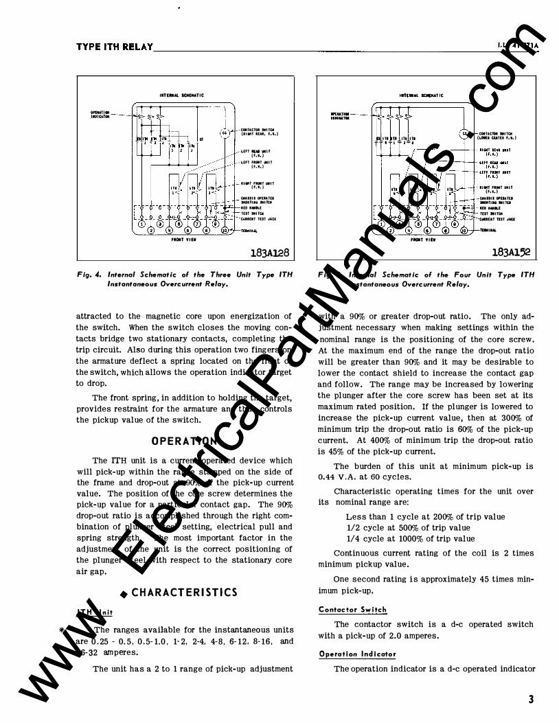
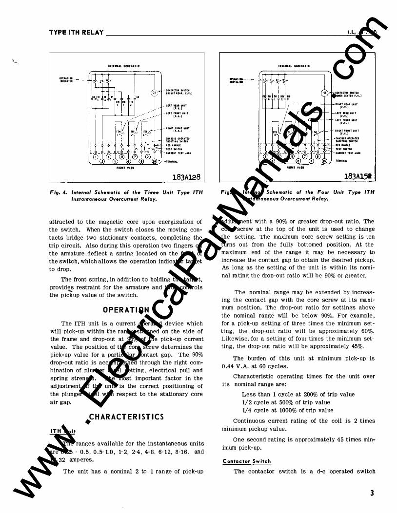
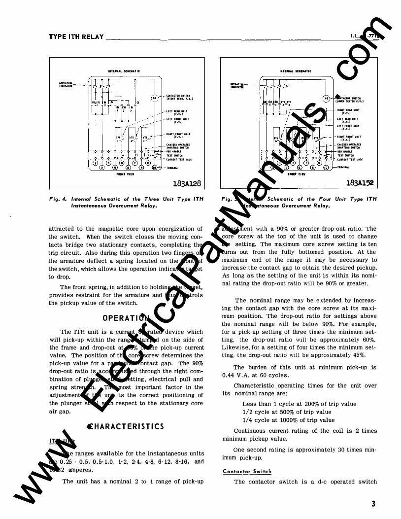
Fig. 4. Internal Schematic of the Three Unit Type ITH Instantaneous Overcurrent Relay.
attracted to the magnetic core upon energization of the switch. When the switch closes the moving contacts bridge two stationary contacts, completing the trip circuit. Also during this operation two fingers on the armature deflect a spring located on the front of the switch, which allows the operation indicator target to drop.
The front spring, in addition to holding the target, provides restraint for the armature and thus controls the pickup value of the switch.
OPE RA T I O N
The ITH unit is a current operated device which will pick-up within the range stamped on the side of the frame and drop-out at 90% of the pick-up current value. The position of the core screw determines the pick-up value for a particular contact gap. The 90% drop-out ratio is accomplished through the right combination of plunger steel setting, electrical pull and spring strength. The most important factor in the adjustment of the unit is the correct positioning of the plunger steel with respect to the stationary core air gap.
C H A RA CT E R I S T JC S
ITH Unit
* The ranges available for the instantaneous units are 0.25 - 0. 5 , 0.5- 1.0 , 1-2, 2-4, 4-8, 6- 12. 8- 16 , and 16-32 amperes.
The unit has a 2 to 1 range of pick-up adjustment
ITII U1 I I
fltOIIT YIEW
COITACTOI SWITCH (LOlli CliTEI f.l.}
llit!T FIOIT UMIT (F ••• )
CHASSIS OPEIATED
MOI:TIIi SWITCII lED tiAIILE
TEST .ITCH
WIIEIT TEST oiW
TUM liM.
183Al52
Fig. 5. Internal Schematic of the Four Unit Type ITH Instantaneous Overcurrent Relay.
with a 90% or greater drop-out ratio. The only adjustment necessary when making settings within the nominal range is the positioning of the core screw. At the maximum end of the range the drop-out ratio will be greater than 90% and it may be desirable to lower the contact shield to increase the contact gap and follow. The range may be increased by lowering the plunger after the core screw has been set at its maximum rated position. If the plunger is lowered to increase the pick-up current value, then at 300% of minimum trip the drop-out ratio is 60% of the pick-up current. At 400% of minimum trip the drop-out ratio is 45% of the pick-up current.
The burden of this unit at minimum pick-up is 0.44 V .A. at 60 cycles.
Characteristic operating times for the unit over its nominal range are:
Less than 1 cycle at 200% of trip value 1/2 cycle at 500% of trip value 1/4 cycle at 1000% of trip value
Continuous current rating of the coil is 2 times minimum pickup value.
One second rating is approximately 45 times minimum pick-up.
Contactor SwItch
The contactor switch is a d-e operated switch with a pick-up of 2.0 amperes.
Opera tion Indicator
The operation indicator is a d-e operated indicator
3 www . El
ectric
alPar
tMan
uals
. com
www . El
ectric
alPar
tMan
uals
. com

TYPE ITH RELAY�------------------------------------------------------
IIDICATIMI COIHACTOII: SWITCK
IMTEIIIIAL SCIIEIIATIC
FROIIT ¥lEW
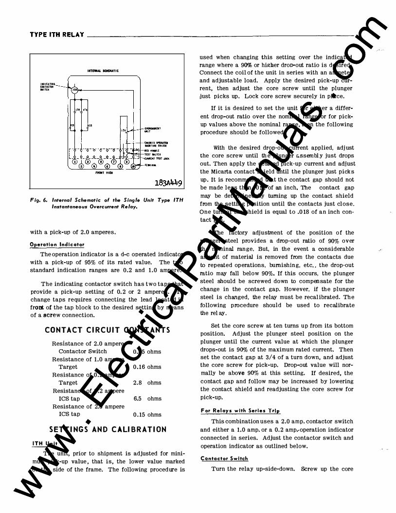
Fig. 6. Internal Schematic ol the Single Unit Type ITH Instantaneous Overcurrent Relay.
with a pick-up of 95% of its rated value. The two standard indication ranges are 0. 2 and 1 . 0 ampere.
The indicating contactor switch has two taps that provide a pick-up setting of 0. 2 or 2 amperes. To change taps requires connecting the lead located in front of the tap block to the desired setting by means of a screw connection.
CONTACT Cl RCU I T CONSTANTS
Resistance of 2.0 ampere Contactor Switch 0.25 ohms
Resistance of 1 .0 ampere Target 0. 16 ohms
Resistance of 0. 2 ampere Target 2.8 ohms
Resistance of 0. 2 ampere ICS tap 6.5 ohms
Resistance of 2.0 ampere ICS tap 0.15 ohms
SETTINGS AND CALl BRAT I ON
I TH Unit
The unit, prior to shipment is adjusted for minimum pick-up value, that is , the lower value marked on the side of the frame. The following procedure is used when changing this setting over the indicated range where a 90% or higher droo-out ratio is desired. Connect the coil of the unit in series with an ammeter and adjustable load. Apply the desired pick-up current, then adjust the core screw until the plunger just picks up. Lock core screw securely in place.
4
If it is desired to set the unit for either a different drop-out ratio over the nominal range or for pickup values above the nominal range, then the following procedure should be followed.
* With the desired drop-out current applied, adjust the core screw until the plunger assembly just drops out. Then apply the desired pick-up current and adjust the Micarta contact shield until the plunger just pick s up. It is recommended that th e contact gap should not be made less than .0 13 of an inch. The contact gap may be determined by turning up the contact shield from the setting position until the contacts just close. One turn of the shield is equal to .0 18 of an inch contact gap.
* The factory adjustment of the position of the plunger steel provides a drop-out ratio of 90% over the nominal range, But, in the event a considerable amount of material is removed from the contacts due to repeated operations, burnishing, etc. , the drop-out ratio may fall below 90%. If this occurs, the plunger steel should be screwed down to comp ensate for the change in the contact gap. However, if the plunger steel is changed, the relay must be recalibrated. Th e following procedure should be used to recalibrate the rel ay.
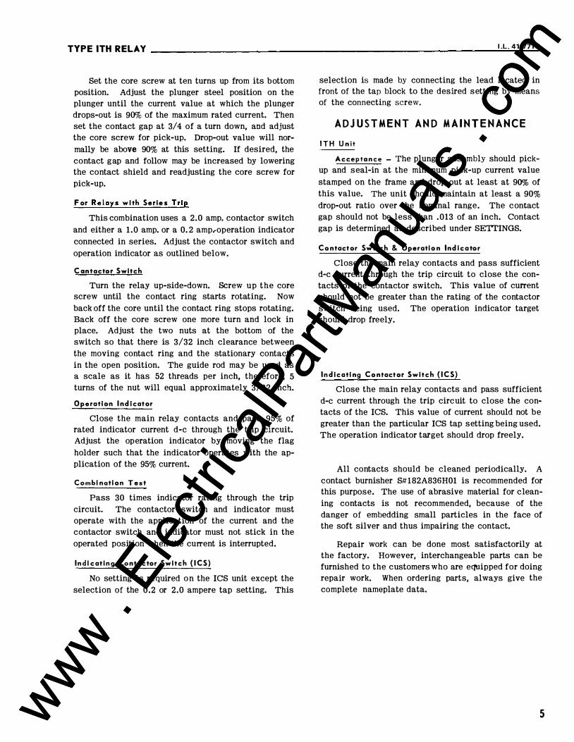
Set the core screw at ten turns up from its bottom position. Adjust the plunger steel position on the plunger until the current value at which the plunger drops-out is 90% of the maximum rated current. Then set the contact gap at 3/4 of a turn down, and adjust
the core screw for pick-up. Drop-out value will normally be above 90% at this setting. If desired, the contact gap and follow may be increased by lowering the contact shield and readjusting the core screw for pick-up.
For Relays with Series Trip
This combination uses a 2.0 amp. contactor switch and either a 1 .0 amp. or a 0. 2 amp. operation indicator connected in series. Adjust the contactor switch and operation indicator as outlined below.
Contoctor Switch
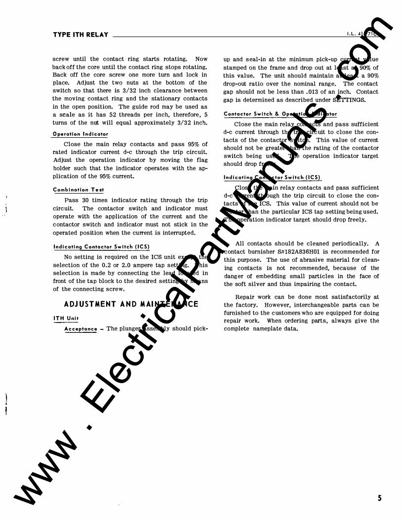
Turn the relay up-side-down. Screw up the core screw until the contact ring starts rotating. Now back off the core until the contact ring stops rotating. Back off the core screw one more turn and lock in place. Adjust the two nuts at the bottom of the switch so that there is 3/32 inch clearance between the moving contact ring and the stationary contacts in the open position. The guide rod may be used as www .
Elec
tricalP
artM
anua
ls . c
om
www . El
ectric
alPar
tMan
uals
. com
l :I
TYPE ITH REL.AY
a scale as it has 52 threads per inch, therefore, 5 turns of the nut will equal approximately 3/32 inch.
Operation Indicator
Close the main relay contacts and pass 95% of rated indicator current d-e through the trip circuit. Adjust the operation indicator by moving the flag holder such that the indicator operates with the application of the 95% current.
Combination Test
Pass 30 times indicator rating through the trip circuit. The contactor switch and indicator must operate with the application of the current and the contactor switch and indicator must not stick in the operated position when the current is interrupted.
I ndicating Contactor Switch (ICS)
No setting is required on the ICS unit except the selection of the 0.2 or 2.0 ampere tap setting. This selection is made by connecting the lead located in front of the tap block to the desired setting by means of the connecting screw.
ADJUSTMENT AND MAINTENANCE
ITH Unit
Acceptance - The plunger assembly should pickup and seal-in at the minimum pick-up current value stamped on the frame and drop out at least at 90% of this value. The unit should maintain at least a 90%
I.L.41-771A
drop-out ratio over the nominal range. The contact gap should not be less than .013 of an inch. Contact gap is determined as described under SETTINGS.
Contactor Switch & Operation Indicator
Close the main relay contacts and pass sufficient d-e current through the trip circuit to close the contacts of the contactor switch. This value of current should not be greater than the rating of the contactor switch being used. The operation indicator target should drop freely.
Indicating Contactor Switch (ICS)
Close the main relay contacts and pass sufficient d-e current through the trip circuit to close the contacts of the ICS. This value of current should not be greater than the particular ICS tap setting being used. The operation indicator target should drop freely.
All contacts should be cleaned periodically. A contact burnisher Slt182A836H01 is recommended for this purpose. The use of abrasive material for cleaning contacts is not recommended, because of the danger of embedding small particles in the face of the soft silver and thus impairing the contact.
Repair work can be done most satisfactorily at the factory. However, interchangeable parts can be furnished to the customers who are equipped for doing repair work. When ordering parts , always give the complete nameplate data.
5 www . El
ectric
alPar
tMan
uals
. com
www . El
ectric
alPar
tMan
uals
. com

TYPE ITH RELAY __ __ __________________________________________________ __
6
I
ii ,,
�
P,.._NEL LOCA.TICN \ �EMI-FLUSH MTG..� PR.OJ"ECTIOI'-\ MTC.. ---.....l
.190-32 SCR.�W
TERMINA-L AND MOUNTING- DE.TA.IL!:>
NOTE: ALL Dl N\�NSIONS. IN INCHES.,
9 16
l 'DIA... 4-HOI..E'S FOR +, 1£)0-32. MI.::.. SC.Rr'NS
I ,..leO -+ �-+--'--
� " '. 11<1 : _2 I .;; I sZ� 8
PANEL CUTOUT t DRIL\.ING F"OR. SEMI-FLIJ�\-4 MIG.
PANE.L Dk\LL\NG 0\< C\JTO\JT F"OR PR.OJ"ECT\0� MTGr.
(FRONT \J\EW)
5'7-D-'7900
'It Fig. 7, Outline and Dri I ling Plan for the Type ITH Relay In the Type FT J J Case.
www . El
ectric
alPar
tMan
uals
. com
www . El
ectric
alPar
tMan
uals
. com

www . El
ectric
alPar
tMan
uals
. com
www . El
ectric
alPar
tMan
uals
. com

W ESTIN GHOUSE E L ECTRIC COR P ORATION RELAY DEPARTMENT NEWARK, N. J.
Printed in U.S. A. www . El
ectric
alPar
tMan
uals
. com
www . El
ectric
alPar
tMan
uals
. com
r I
INSTALLATION
Westinghouse 1. L. 41-7718
• OPERATION • MAINTENANCE
INSTRUCTIONS
TYPE ITH RELAY
CAUTION Before putting relays into service, remove all blocking which may have been inserted for the purpose of securing the parts during shipment, make sure that all moving parts operate freely, inspect the contacts to see that they are clean and close properly, and operate the relay to check the settings and electrical connections.
APPL I CATION
ITH relays may be utilized as overcurrent fault detectors or as instantaneous overcurrent trip units. They are particularly suitable as fault detectors because of their 90% dropout ratio and because of their compact size. Their size also makes them desirable for use in supplementing existing time-overcurrent
relays or to provide a second set of instantaneous trip units .
CONTENT
The relays consist of one, three or four high dropout instantaneous units with an equal number of operation indicators and one contactor switch. In the single unit relay the d-e indicating contactor switch is used in place of an operation indicator and contactor switch.
CONSTRUCTION
The construction of the individual units is as follows:
The H ig h Drop-Out Instantaneous Trip Unit (ITH )
The high drop-out instantaneous trip unit is a small solenoid type device (Fig. 1). A plunger assembly (Fig. 2) rides up and down on a vertical guide rod in the center of the solenoid coil. The plunger assembly consists of a bushing which is threaded on the moving plunger and locked in place by a nut, and a silver disc which rests on a helical compression spring at the lower end of the plunger. The guide rod is fastened to the stationary core which in turn is held in place by the insulating plate on which the stationary contacts are mounted. The stationary core
SUPERSEDES I.L. 41-771A *Denotes change from superseded issue
consists of two steel sections separated by a nonmagnetic ring. This non-magnetic ring provides an air gap in which the plunger steel floats. When the coil is energized, the plunger assembly moves upward carrying the silver disc which bridges three conicalshaped stationary contacts. In this position the helical spring is compressed and the plunger is free to move while the contact disc remains stationary. Thus, a-c vibrations of the plunger assembly are prevented from causing contact chattering. A Micarta disc which acts as a shield for the contact plate, screws on the bottom of the guide rod and is locked in position by a small nut. The adjustable core screw in the top of the frame provides the principal means for adjusting the current operating values.
Contactor Switch
The d-e contactor switch in the relay is a small solenoid type switch. A cylindrical plunger with a silver di�c mounted on its lower end moves in the core of the solenoid.
As the plunger travels upward, the disc bridges three silver stationary contacts. The coil is in series with the main contacts of the relay and with the trip coil of the breaker. When the relay contacts close, the coil becomes energized and closes the switch contacts. This shunts the main relay contacts, thereby relieving them of the duty of carrying tripping current. These contacts remain closed until the trip circuit is opened by the auxiliary switch on the breaker.
Operation Indicator
The operation indicator is a small solenoid coil connected in the trip circuit. When the coil is energized a spring-restrained armature releases the white target which falls by gravity to indicate completion of the trip circuit. The indicator may be reset from outside of the case.
Indicating Contactor Switch Unit (ICS)
The d-e indicating contactor switch (Fig. 3) is a small clapper type device. A magnetic armature, to which leaf-spring mounted contacts are attached, is
EFFECTIVE DECEMBER 1961 www . El
ectric
alPar
tMan
uals
. com
www . El
ectric
alPar
tMan
uals
. com

TYPE ITH RELAY
Fig. J. High Drop-Out Instantaneous Trip Unit (ITH). Fig. 2. Plunger Assembly for ITH Unit.
Fig, 3. lndlcoting Contactor Switch (ICS).
2 www . El
ectric
alPar
tMan
uals
. com
www . El
ectric
alPar
tMan
uals
. com
TYPE ITH RELAY ________________________________________________________ �I�.L�·�41�-�77�1B
OI'£11ATIOII IIIDICATOII
INTEMIAL SCMfMATIC
FROIIT YIEW
-COM fACTOR SWITCtl (IIIQtlT REAR, F..'C.)
__...--LEU lUI UIIT (F,i,)
-LEFT FIOIIT UIIIT (F,i,)
RlatlT fiOIT UIIIT (f. • •• )
CHASSIS OPERATED SHOIITIII\1 SWITCH RED KAIIOL.E TEST SWITCtl CUUEIH TEST JACK
TUMIIIAI.
183Al28
Fig. 4. Internal Schematic of the Three Unit Type ITH Instantaneous Overcurrent Relay.
attracted to the magnetic core upon energization of the switch. When the switch closes the moving contacts bridge two stationary contacts, completing the trip circuit. Also during this operation two fingers on the armature deflect a spring located on the front of the switch, which allows the operation indicator target to drop.
The front spring , in addition to holding the target, provid� restraint for the armature and thus controls the pickup value of the switch.
OPERATION
The ITH unit is a current operated device which will pick-up within the range stamped on the side of the frame and drop-out at 90% of the pick-up current value. The position of the core screw determines the pick-up value for a particular contact gap. The 90% drop-out ratio is accomplished through the right combination of plunger steel setting, electrical pull and spring strength. The most important factor in the adjustment of the unit is the correct positioning of the plunger steel with respect to the stationary core air gap.
CHARACTER I ST I CS
I TH Unit
The ranges available for the instantaneous units are 0 . 25 - 0.5 , 0 . 5- 1.0 , 1-2, 2-4 , 4-8, 6- 12, 8-16 , and 16- 32 amp eres.
The unit has a nominal 2 to 1 range of pick-up
1'01 lH 0 I
IWTEII .. l SCHEMATIC
COITACTOI SWITCtl (LIMI CEITU f..t.)
�����---1----L tlitll IW UIIIT
4-_.__.__j (f.i.)
FIIOIIT YIEW
LEfT lUI UIIIT (f.i,)
LEFT FIOIIT UIIT (f. 'C.)
llliltT FIIHIT UIIIT (F. I,)
CIIASSU Of>EIA T£D SIIOITIIQ SlfiTCtl
lED HIIDl.( T£ST :WITCtl CUIIOT TEST .IACI
TUMIIAI.
183Al51
Fig. 5. Internal Schematic of the Four Unit Type ITH Instantaneous Overcurrent Relay.
adjustment with a 90% or greater drop-out ratio. The core screw at the top of the unit is used to change the setting. The maximum core screw setting is ten turns out from the fully bottomed position. At the maximum end of the range it may be necessary to increa se the contact gap to obtain the desired pickup. As long as the setting of the unit is within its nominal rating the drop-out ratio will be 90% or greater.
The nominal range may be extended by increasing the contact gap with the core screw at i ts maximum position. The drop-out ratio for settings above the nominal range will be below 90%. For example , for a pick-up setting of three times the minimum setting, the drop-out ratio will be approximately 60%. Likewise, for a setting of four times the minimum setting, the drop-out ratio will be approximately 45%.
The burden of this unit at minimum pick-up is 0.44 V .A. at 60 cycles.
Characteristic operating times for the unit over its nominal range are:
Less than 1 cycle at 200% of trip value 1/2 cycle at 500% of trip value 1/4 cycle at 1000% of trip value
Continuous current rating of the coil is 2 times minimum pickup value.
One second rating is approximately 45 times minimum pick-up.
Contactor SwItch
The contactor switch is a d-e operated switch
3 www . El
ectric
alPar
tMan
uals
. com
www . El
ectric
alPar
tMan
uals
. com

TYPE ITH RELAY __ __ __ __ __ __ __ __ __ ____________________ ________________ __
IIDICATIII COlT ACTOR SWITCII
111'tiiNI. ICIIIJIATIC
fiiOIIT YIIW
Fig. 6. Internal Schematic of the Single Unit Type ITH Instantaneous Overcurrent Relay,
with a pick-up of 2.0 amperes.
Operation Indicator
The operation indicator is a d-e operated indicator with a pick-up of 95% of its rated value. The two standard indication ranges are 0.2 and 1 .0 ampere.
The indicating contactor switch has two taps that provide a pick-up setting of 0. 2 or 2 amperes. To change taps requires connecting the lead located in from of the tap block to the desired setting by means of a screw connection.
CONTACT CIRCUIT CONSTANTS
Resistance of 2.0 ampere Contactor Switch 0 .25 ohms
Resistance of 1.0 ampere Target 0. 16 ohms
Resistance of 0.2 ampere Target 2.8 ohms
Resistance of 0.2 ampere ICS tap 6.5 ohms
Resistance of 2.0 ampere ICS tap 0. 15 ohms
SETTINGS AND CALIBRATION
ITH Unit
The unit, prior to shipment is adjusted for minimum pick-up value, that is , the lower value marked on the side of the frame. The following procedure is
used when changing this setting over the indicated range where a 90% or higher droo-out ratio is desired. Connect the coil of the unit in series with an ammeter and adjustable load. Apply the desired pick-up current, then adjust the core screw until the plunger just picks up. Lock core screw securely in place.
If it is desired to set the unit for either a different drop-out ratio over the nominal range or for pickup values above the nominal range, then the following procedure should be followed.
With the desired drop-out current applied, adjust the core screw until th e plunger u.ssembly just drops out. Then apply the desired pick-up current and adjust the Micarta contact shield until the plunger just pick s up. It is recommended that th e contact gap should not be made less than .0 13 of an inch, The contact gap may be detennined by turning up the contact shield from the setting position until the contacts just close. One tum of the shield is equal to .0 18 of an inch contact gap.
The factory adjustment of the position of the plunger steel provides a drop-out ratio of 90% over the nominal range, But, in the event a considerable amount of material is removed from the contacts due to repeated operations, burnishing, etc. , the drop-out ratio may fall below 90%. If this occurs, the plunger steel should be screwed down to compmsate for the change in the contact gap. However, if the plunger steel is changed, the relay must be recalibrated. Th e following procedure should be used to recalibrate th e relay.
Set the core screw at ten turns up from its bottom position. Adjust the plunger steel position on the plunger until the current value at which the plunger drops-out is 90% of the maximum rated current. Then set the contact gap at 3/4 of a turn down, and adjust the core screw for pick-up. Drop-out value will normally be aboye 90% at this setting. If desired, the contact gap and follow may be increased by lowering the contact shield and readjusting the core screw for pick-up.
For Relays with Series Trip
This combination uses a 2.0 amp. contactor switch and either a 1.0 amp. or a 0. 2 amp.-operation indicator connected in series. Adjust the contactor switch and operation indicator as outlined below.
Contactor Switch
Turn the relay up-side-down. Screw up the core
j
i r
l
www . El
ectric
alPar
tMan
uals
. com
www . El
ectric
alPar
tMan
uals
. com

J 1
TYPE ITH RELAY
screw until the contact ring starts rotating. Now back off the core until the contact ring stops rotating. Back off the core screw one more turn and lock in place. Adjust the two nuts at the bottom of the switch so that there is 3/32 inch clearance between the moving contact ring and the stationary contacts in the open position. The guide rod may be used as a scale as it has 52 threads per inch, therefore , 5 turns of the nut will equal approximately 3/32 inch.
Operation Indicator
Close the main relay contacts and pass 95% of rated indicator current d-e through the trip circuit. Adjust the operation indicator by moving the flag holder such that the indicator operates with the application of the 95% current.
Combination Test
Pass 30 times indicator rating through the trip circuit. The contactor swit9h and indicator must operate with the application of the current and the contactor switch and indicator must not stick in the operated position when the current is interrupted.
Indicating Contactor Switch (ICS)
No setting is required on the ICS unit except the selection of the 0.2 or 2.0 ampere tap setting. This selection is made by connecting the lead located in front of the tap block to the desired setting by means of the connecting screw.
ADJUSTMENT AND MAI NTENANCE
ITH Unit
Acceptance - The plunger assembly should pick-
I.L. 41-nlB
up and seal-in at the minimum pick-up current value stamped on the frame and drop out at least at 90% of this value. The unit should maintain at least a 90% drop-out ratio over the nominal range. The contact gap should not be less than .013 of an inch. Contact gap is determined as described under SETTINGS.
Contactor Switch & Operation Indicator
Close the main relay contacts and pass sufficient d-e current through the trip circuit to close the contacts of the contactor switch. This value of current should not be greater than the rating of the contactor switch being used. The operation indicator target should drop freely.
Indicating Contactor Switch (ICS)
Close the main relay contacts and pass sufficient d-e current through the trip circuit to close the contacts of the ICS. This value of current should not be greater than the particular ICS tap setting being used. The operation indicator target should drop freely.
All contacts should be cleaned periodically. A contact burnisher S#l82A836H01 is recommended for this purpose. The use of abrasive material for cleaning contacts is not recommended, because of the dang er of embedding small particles in the face of the soft silver and thus impairing the contact.
Repair work can be done most satisfactorily at the factory. However, interchangeable parts can be furnished to the customers who are equipped for doing repair work. When ordering parts, always give the complete nameplate data.
5 www . El
ectric
alPar
tMan
uals
. com
www . El
ectric
alPar
tMan
uals
. com

TYPE ITH RELAY ______________________________________________________ __
6
t��+j ,, ,_N:C COCAT,ON� '!.EMI-FLUS\-1 MT�.i PR.OJ"ECTIO� MTG. ---'
.190-3Z. 5CR.E.W
T£RMI�A.L A.ND MOUNTING- DE.TA.I�
NOTE: ALL DIN\t=:NSIONS IN IN'::HES,
9 16
PANEL CUTOUT t DRILLING F"OR SEMI-FLU&'-' MTG.
FOR
>/1: Fig, 7, Outline and Dri /ling Plan for the Type ITH Relay In the Type FT J J Case.
57-D-7900
www . El
ectric
alPar
tMan
uals
. com
www . El
ectric
alPar
tMan
uals
. com

www . El
ectric
alPar
tMan
uals
. com
www . El
ectric
alPar
tMan
uals
. com

W ESTIN GHOUSE E L ECTRIC COR P ORATION RELAY DEPARTMENT NEWARK, N. J.
Printed in U. S. A. www . El
ectric
alPar
tMan
uals
. com
www . El
ectric
alPar
tMan
uals
. com

f '
I ,
Westinghouse I .L. 4 1 -771 C
INSTALLATION • OPERATION • MAINTENANCE
INSTRUCT IONS
TYPE ITH RELAY
CAUTION Before putting relays into service, remove all blocking which may have been inserted for the purpose of securing the parts during shipment, make sure that all moving parts operate freely, inspect the contacts to see that they are clean and close properly, and operate the relay to check the settings and electrical connections.
APPLI CAT I ON
ITH relays may be utilized as overcurrent fault detectors or as instantaneous overcurrent trip units. They are particularly suitable as fault detectors because of their 90% dropout ratio and because of their compact size. Their size also makes them desirable for use in supplementing existing time-overcurrent relays or to provide a second set of instantaneous trip units .
CONTENT
The relays consist of one, three or four high dropout instantaneous units with an equal number of operation indicators and one contactor switch. In the single unit relay the d-e indicating contactor switch is used in place of an operation indicator and contactor switch.
CONSTRUCTION
The construction of the individual units is as follows:
The High Drop-Out Instantaneous Trip Unit (ITH)
The high drop-out instantaneous trip unit is a small solenoid type device (Fig. 1). A plunger assembly (Fig. 2) rides up and down on a vertical guide rod in the center of the solenoid coil. The plunger assembly consists of a bushing which is threaded on the moving plunger and locked in place by a nut, and a silver disc which rests on a helical compression spring at the lower end of the plunger. The guide rod is fastened to the stationary core which in turn is held in place by the insulating plate on which the stationary contacts are mounted. The stationary core
SUPERSEDES I.L 4 1 -771 B *Denotes change from superseded issue.
consists of two �teel sections separated by a nonmagnetic ring. This non-magnetic ring provides an air gap in which the plunger steel floats. When the coil is energized, the plunger assembly moves upward carrying the silver disc which bridges three conicalshaped stationary contacts. In this position the helical spring is compressed and the plunger is free to move while the contact disc remains stationary. Thus, a-c vibrations of the plunger assembly are prevented from causing contact chattering. A Micarta disc which acts as a shield for the contact plate, screws on the bottom of the guide rod and is locked in position by a small nut. The adjustable core screw in the top of the frame provides the principal means for adjusting the current operating values.
Contactor Switch
The d-e contactor switch in the relay is a small solenoid type switch. A cylindrical plunger with a silver di�c mounted --en its lower end moves in the core of the solenoid.
As the plunger travels upward, the disc bridges three silver stationary contacts. The coil is in series with the main contacts of the relay and with the trip coil of the breaker. When the relay contacts close, the coil becomes energized and closes the switch contacts. This shunts the main relay contacts, thereby relieving them of the duty of carrying tripping cur
rent. These contacts remain closed until the trip circuit is opened by the auxiliary switch on the breaker.
Operation Indicator
The operation indicator is a small solenoid coil connected in the trip circuit. When the coil is energized a spring-restrained armature releases the white target which falls by gravity to indicate completion of the trip circuit. The indicator may be reset from outside of the case.
Indicating Contactor Switch Unit (ICS)
The d-e indicating contactor switch (Fig. 3) is a small clapper type device. A magnetic armature , to which leaf-spring mounted contacts are attached , is
EFFECTIVE DECEMBE R 1 964 www . El
ectric
alPar
tMan
uals
. com
www . El
ectric
alPar
tMan
uals
. com

TYPE ITH RELAY
Fig. J, High Drop-Out Instantaneous Trip Unit (ITH). Fig. 2. Plunger Assembly for ITH Unit,
Fig, 3. lnd/coting Contactor Switch (ICS),
2 www . El
ectric
alPar
tMan
uals
. com
www . El
ectric
alPar
tMan
uals
. com

TYPE ITH RELAY __________________________________________________________ I_.L_._41_-7_7 __ lc
IITU .. L SCIIWTIC
fiiGIIT YIEW
COIITACTOR HITCII (IIMT lUI, F..l.)
LEFT llAI UIIT , .... )
L.ffl F .. T !MIT , .... )
RIQMT FIOIT Ill IT , .... )
CHASSIS OPEIATO SltOITIIi SWITCM ltED MMK.£
TEST SWITCI C6tllDT TEST .iltl
183Al28
Fig. 4. Internal Schematic of the Three Unit Type ITH Instantaneous Overcurrent Relay.
attracted to the magnetic core upon energization of the switch. When the switch closes the moving contacts bridge two stationary contacts, completing the trip circuit. Also during this operation two fingers on the armature deflect a spring located on the front of the switch, which allows the operation indicator target to drop.
The front spring, in addition to holding the target, provides restraint for the armature and thus controls the pickup value of the switch.
OPERATI ON
The ITH unit is a current operated device which will pick-up within the range stamped on the side of the frame and drop-out at 90% of the pick-up current value. The position of the core screw determines the pick-up value for a particular contact gap. The 90% drop-out ratio is accomplished through the right combination of plunger steel setting, electrical pull and spring strength. The most important factor in the adjustment of the unit is the correct positioning of the plunger steel with respect to the stationary core air gap.
CHARACTERI STI CS
ITH Unit
The ranges available for the instantaneous units are 0.25 - 0. 5 . 0 .5- 1 .0 , 1·2, 2·4, 4-8, 6- 12 . 8·16, and 16-32 amperes.
The unit has a nominal 2 to 1 range of pick-up
llllll I I
IITE .. AI. SCIIWTIC
COIITACTOI WITCI (&.MI WTEI f.l.)
,-------+----1- IIMT HAl UIIIT L+-+. .... .J , •••• ) �---1---� Lffl lEAl IIIIT
fiiCIIIT YIEW
, .... ) --+-+- LEFT FICIIT UIIT
, . .. . )
IIIIIT FIIIT UIIT , .... )
CIIAUIS OPEIAT£1 IIOITIUSWITCI WUIII.£ TtST WITCII CUIIUT liST .. ACI
TUM liM.
183Al52
Fig. 5. Internal Schematic of the Four Unit Type ITH Instantaneous Overcurrent Relay.
adjustment with a 90% or greater drop-out ratio. The core screw at the top of the unit is used to change the setting. The maximum core screw setting is ten turns out from the fully bottomed position. At the maximum end of the range it may be necessary to increase the contact gap to obtain the desired pickup. As long as the setting of the unit is within its nominal rating the drop-out ratio will be 90% or greater.
The nominal range may be extended by increasing the contact gap with the core screw at i ts maximum position. The drop-out ratio for settings above the nominal range will be below 90%. For example, for a pick-up setting of three time s the minimum setting, the drop-out ratio will be approximately 60%. Likewise, for a setting of four times the minimum setting, the drop-out ratio will be approximately 45%.
The burden of this unit at minimum pick-up is 0.44 V .A. at 60 cycles.
Characteristic operating times for the unit over its nominal range are:
Less than 1 cycle at 200% of trip value 1/2 cycle at 500% of trip value 1/4 cycle at 1000% of trip value
Continuous current rating of the coil is 2 times minimum pickup value.
* One second rating is approximately 30 times minimum pick-up .
Contactor Switch
The contactor switch is a d-e operated switch
3 www . El
ectric
alPar
tMan
uals
. com
www . El
ectric
alPar
tMan
uals
. com

TYPE ITH RELAY ____________________________________________________ ____ __
IIOICATINI COITACTOI SWITCH
IITIIUI. ICIIIIIATIC
fiiOIIT fllll
ST aw•TtN
UIIENT ttST JACI
F lg. 6. Internal Schematic of the Single Unit Type ITH Instantaneous Overcurrent Relay.
with a pick-up of 2.0 amperes.
Operation Indicator
The operation indicator is a d-e operated indicator with a pick-up of 95% of its rated value. The two standard indication ranges are 0 .2 and 1 .0 ampere.
The indicating contactor switch has two taps that provide a pick-up setting of 0.2 or 2 amperes. To change taps requires connecting the lead located in frott of the tap block to the desired setting by means of a screw connection.
CONTACT Cl RCU I T CONSTANTS
Resistance of 2.0 ampere Contactor Switch 0 .25 ohms
Resistance of 1 .0 ampere Target 0. 16 ohms
Resistance of 0 .2 ampere Target 2 .8 ohms
Resistance of 0.2 ampere ICS tap 6.5 ohms
Resistance of 2 .0 ampere ICS tap 0 .15 ohms
SETT I NGS AND CALI BRATI ON
ITH Unit
The unit, prior to shipment is adjusted for minimum pick-up value, that is, the lower value marked on the side of the frame. The following procedure is
4
used when changing this setting over the indicated range where a 90% or hie:her droo-out ratio is desired. Connect the coil of the unit in series with an ammeter and adjustable load. Apply the desired pick-up current, then adjust the core screw until the plunger just picks up. Lock core screw securely in place.
If it is desired to set the unit for either a different drop-out ratio over the nominal range or for pickup values above the nominal range, then the following procedure should be followed.
With the desired drop-out current applied, adjust the core screw until the plunger G.ssembly just drops out. Then apply the desired pick-up current and adjust the Micarta contact shield until the plunger just pick s up. It is recommended that th e contact gap should not be made less than .0 13 of an inch, The contact gap may be detennined by turning up the contact shiel d from the setting position until the contacts just close. One tum of the shi eld is equal to .0 18 of an inch contact gap .
The factory adjustment of the po sition of the plunger steel provides a drop-out ratio of 90% over the nominal range, But, in the event a considerable amount of material is removed from the contacts due to repeated operations, burnishing, etc. , the drop-out ratio may fall below 90%. If this occurs, the plunger steel should be screwed down to compmsate for the change in the contact gap. However, if the plunger steel is changed, the relay must b e recalibrated. The following procedure should be used to recalibrate the relay.
Set the core screw at ten turns up from its bottom position. Adjust the plunger steel position on the plunger until the current value at which the plunger drops-out is 90% of the maximum rated current. Then set the contact gap at 3/4 of a turn down, and adjust the core screw for pick-up. Drop-out value will normally be above 90% at this setting. If desired, the contact gap and follow may be increased by lowering the contact shield and readjusting the core screw for pick-up.
For Relays with Series Trip
This combination uses a 2 .0 amp. contactor switch and either a 1 .0 amp. or a 0 . 2 amp.-operation indicator connected in series. Adjust the contactor switch and operation indicator as outlined below.
Contactor Switch
Turn the relay up-side-down. Screw up the core
www . El
ectric
alPar
tMan
uals
. com
www . El
ectric
alPar
tMan
uals
. com
}
f
TYPE .ITH RELAY
screw until the contact ring starts rotating. Now back off the core until the contact ring stops rotating. Back off the core screw one more turn and lock in place. Adjust the two nuts at the bottom of the switch so that there is 3/32 inch clearance between the moving contact ring and the stationary contacts in the open position. The guide rod may be used as a scale as it has 52 threads per inch, therefore , 5 turns of the nut will equal approximately 3/32 inch.
0 peration lndi cator
Close the main relay contacts and pass 95% of rated indicator current d-e through the trip circuit. Adjust the operation indicator by moving the flag holder such that the indicator operates with the application of the 95% current.
Combination Test
Pass 30 times indicator rating through the trip circuit. The contactor swit�h and indicator must operate with the application of the current and the contactor switch and indicator must not stick in the operated position when the current is interrupted.
Indicating Contactor Switch (ICS)
No setting is required on the ICS unit except the selection of the 0.2 or 2.0 ampere tap setting. This selection is made by connecting the lead located in front of the tap block to the desired setting by means of the connecting screw.
ADJUSTMENT AND MAI NTENANCE
ITH Unit
Acceptance - The plunger assembly should pick-
I.L. 41-771C
up and seal-in at the minimum pick-up current value stamped on the frame and drop out at least at 90% of this value. The unit should maintain at least a 90% drop-out ratio over the nominal range. The contact gap should not be less than . 013 of an inch. Contact gap is determined as described under SETTINGS.
Contactor Switch & Operation Indicator
Close the main relay contacts and pass sufficient d-e current through the trip circuit to close the contacts of the contactor switch. This value of current should not be greater than the rating of the contactor switch being used. The operation indicator target should drop freely.
Indicating Contactor Switch (ICS)
Close the main relay contacts and pass sufficient d-e current through the trip circuit to close the contacts of the ICS. This value of current should not be greater than the particular ICS tap setting being used. The operation indicator target should drop freely.
All contacts should be cleaned periodically. A contact burnisher S#l82A836H01 is recommended for this purpose. The use of abrasive material for cleaning contacts is not recommended, because of the danger of embedding small particles in the face of the soft silver and thus impairing the contact.
Repair work can be done most satisfactorily at the factory. However, interchangeable parts can be furnished to the customers who are equipped for doing repair work. When ordering parts, always give the complete nameplate data.
5 www . El
ectric
alPar
tMan
uals
. com
www . El
ectric
alPar
tMan
uals
. com

TYPE ITH RELAY ________________________________________ ________________ _
6
�:c coc�TOON� �EM I -FLUSH MT::..i PROJECTIO� MTG. ---�
.190-3Z �RE.W
T"ER"-41 t-.1/>..L I>..ND MOUNTING- DE.T/>..ILS.
NOTE: ALL Dl N\1=-NSIONS IN IN::HES,
9 16
PANEL CUTOUT tDRIL\JNG F"OR SEMI-FLU&H MTG.
PANEL DR\LLING 0� CUTOUT F"OR PROJi:CI\0� MT4.
(FRONT \J\EW)
Fig, 7. Outline anJ Dri I ling Plan lor the Type ITH Relay in the Type FTl J Case.
57-D-7900
www . El
ectric
alPar
tMan
uals
. com
www . El
ectric
alPar
tMan
uals
. com

www . El
ectric
alPar
tMan
uals
. com
www . El
ectric
alPar
tMan
uals
. com

WESTINGHOUSE ELECTRIC CORPORATION RELAY-INSTRUMENT DIVISION NEWARK, N. J.
Printed in U.S.A. www . El
ectric
alPar
tMan
uals
. com
www . El
ectric
alPar
tMan
uals
. com
INSTALL A Tl 0 N Westinghouse I.L. 41-771D
• OPERATION • MAINTENANCE
INSTRUCTIONS
TYPE ITH RELAY
CAUTION Before putting relays into service, remove all blocking which may have been inserted for the purpose of securing the parts during shipment , make sure that all moving parts operate freely, inspect the contacts to see that they are clean and close properly, and operate the relay to check the settings and electrical connections.
APPL I CAT I ON
ITH relays may be utilized as overcurrent fault detectors or as instantaneous overcurrent trip units. They are particularly suitable as fault detectors because of their 90% dropout ratio and because of their compact size. Their size also makes them desirable for use in supplementing existing time-overcurrent relays or to provide a second set of instantaneous trip units .
CON T EN T
The relays consist of one, three or four high dropout instantaneous units with an equal number of operation indicators and one contactor switch. In the single unit relay the d-e indicating contactor switch is used in place of an operation indicator and contactor switch.
CON ST RU CT I ON
The construction of the individual units is as follows:
The H igh Drop-Out Instantaneous Trip Unit (ITH )
The high drop-out instantaneous trip unit is a small solenoid type device (Fig. 1). A plunger assembly (Fig. 2) rides up and down on a vertical guide rod in the center of the solenoid coil. The plunger assembly consists of a bushing which is threaded on the moving plunger and locked in place by a nut , and a silver disc which rests on a helical compression spring at the lower end of the plunger. The guide rod is fastened to the stationary core which in turn is held in place by the insulating plate on which the stationary contacts are mounted. The stationary core
SUPERSEDES I.L. 41-771C *Denotes change from superseded issue.
consists of two �teel sections separated by a nonmagnetic ring. This non-magnetic ring provides an air gap in which the plunger steel floats. When the coil is energized, the plunger assembly moves upward carrying the silver disc which bridges three conicalshaped stationary contacts. In this position the helical spring is compressed and the plunger is free to move while the contact disc remains stationary. Thus, a-c vibrations of the plunger assembly are prevented from causing contact chattering. A Micarta disc which acts as a shield for the contact plate, screws on the bottom of the guide rod and is locked in position by a small nut. The adjustable core screw in the top of the frame provides the principal means for adjusting the current operating values.
Contactor Switch
The d-e contactor switch in the relay is a small solenoid type switch. A cylindrical plunger with a silver dif?C mounted on its lower end moves in the core of the solenoid.
As the plunger travels upward, the disc bridges three silver stationary contacts. The coil is in series with the main contacts of the relay and with the trip coil of the breaker. When the relay contacts close, the coil becomes energized and closes the switch contacts. This shunts the main relay contacts , thereby relieving them of the duty of carrying tripping current. These contacts remain closed until the trip circuit is opened by the auxiliary switch on the breaker.
Operation Indicator
The operation indicator is a small solenoid coil connected in the trip circuit. When the coil is energized a spring-restrained armature releases the white target which falls by gravity to indicate completion of the trip circuit. The indicator may be reset from outside of the case.
Indicating Contactor Switch Unit (ICS)
The d-e indicating contactor switch (Fig. 3) is a small clapper type device. A magnetic armature , to which leaf-spring mounted contacts are attached, is
EFFE CTIVE DECEMBE R 1968 www . El
ectric
alPar
tMan
uals
. com
www . El
ectric
alPar
tMan
uals
. com
TYPE ITH RELAY
* Fig. 1. High Drop-Out Instantaneous Trip Unit (ITH). Fig, 2. Plunger Assembly for ITH Unit,
Fig. 3. lndicoting Contactor Switch (ICS).
2 www . El
ectric
alPar
tMan
uals
. com
www . El
ectric
alPar
tMan
uals
. com
TYPE ITH RELAY ____________________________________________ ______________ r�. L�-�4�1 -�7 7�1 0
IIITEbAL SCHEMAT IC
FROIIT YllW
� COMTACTOR SWITCH (Riit!T IU.It, f.1.)
LEFT lEAl UIIT (F ••• )
- - LEFT fUll UIIT <•-•- )
Rlit!T FICMIT UIIT <•-•- )
CHASSIS OPERATED SHOITIIQ SWITCM
lED tiMkE
TEST SWITCI
CUIUJIT TEST .IAU
183Al28
Fig. 4. Internal Schematic of the Three Unit Type ITH Instantaneous Overcurrent Relay.
attracted to the magnetic core upon energization of the switch. When the switch closes the moving contacts bridge two stationary contacts, completing the trip circuit. Also during this operation two fingers on the armature deflect a spring located on the front of the switch, which allows the operation indicator target to drop.
The front spring, in addition to holding the target, provides restraint for the armature and thus controls the pickup value of the switch.
OPE RAT I ON
The ITH unit is a current operated device which will pick-up within the range stamped on the side of the frame and drop-out at 90% of the pick-up current value. The position of the core screw determines the pick-up value for a particular contact gap. The 90% drop-out ratio is accomplished through the right combination of plunger steel setting, electrical pull and spring strength. The most important factor in the adj ustment of the unit is the correct positioning of the plunger steel with respect to the stationary core air gap.
CH A RA CT E RI ST I CS
ITH Unit
The ranges available for the instantaneous units are 0 . 25 - 0. 5 . 0 . 5- 1 .0 , 1- 2, 2-4. 4-8, 6- 12. 8-16 , and 16- 32 amperes.
The unit has a nominal 2 to 1 range of pick-up
IOTliiiiAL SCHWTIC
COITACTOI SWITCI (LMI WTEI f. I. )
r--------t-___j__ IIIMIT IW liMIT 4---+--+_j (f ••• ) r---�.L__l_ LEFT lUI Ill IT
(F ••• ) LEFT FIOIT UIIIT
( F ••• ) lllitll FIOIT UIIIT ( F ••• )
L___,__-r-::�:!a or_:��· lED KAliL( TEST SWITCit
CUIIEIT TEST oiAU
TEINIIM.
183Al52
Fig. 5. Internal Schematic of the Four Unit Type ITH Instantaneous Overcurrent Relay.
adjustment with a 90% or greater drop-out ratio. The core screw at the top of the unit is used to change the setting. The maximum core screw setting is ten turns out from the fully bottomed position. At the maximum end of the range it may be necessary to increase the contact gap to obtain the desired pickup. As long as the setting of the unit is within its nominal rating the drop-out ratio will be 90% or greater.
The nominal range may be e xtended by increasing the contact gap with the core screw at its maximum position. The drop-out ratio for settings above the nominal range will be below 90%. For example, for a pick-up setting of three time s the minimum setting, the drop-out ratio will be approximately 60%. Likewise, for a setting of four times the minimum setting, the drop-out ratio will be approximately 45%.
The burden of this unit at minimum pick-up is 0.44 V .A. at 60 cycles.
Characteristic operating times for the unit over its nominal range are :
Less than 1 cycle at 200% o f trip value 1/2 cycle at 500% of trip value 1/4 cycle at 1000% of trip value
Continuous current rating of the coil is 2 times minimum pickup value.
One second rating is approximately 30 times minimum pick-up.
Contactor S w i tc h
The contactor switch is a d-e operated switch
3 www . El
ectric
alPar
tMan
uals
. com
www . El
ectric
alPar
tMan
uals
. com
TYPE ITH RELAY ______ __________________________________ ______________ __
IMOICATUUI COUACTOR SWITCH
cs
IITIIUL ICIIEIIATIC
fiiOIIT YllV
Fig. 6. Internal Schematic ol the Single Unit Type ITH Instantaneous Overcurrent Relay,
with a pick-up of 2.0 amperes.
Operation Indi c ator
The operation indicator is a d-e operated indicator with a pick-up of 95% of its rated value. The two standard indication ranges are 0.2 and 1 .0 ampere.
The indicating contactor switch has two taps that provide a pick-up setting of 0. 2 or 2 amperes. To change taps requires connecting the lead located in front of the tap block to the desired setting by means of a screw connection.
CO N T A CT Cl R CU I T CON ST AN T S
Resistance of 2.0 ampere Contactor Switch 0.25 ohms
Resistance of 1 .0 ampere Target 0 . 16 ohms
Resistance of 0 .2 ampere Target 2.8 ohms
Resistance of 0.2 ampere ICS tap 6.5 ohms
Resistance of 2.0 ampere ICS tap 0 . 15 ohms
S ET T I N G S AN D CALl BRAT I ON
ITH Unit
The unit, prior to shipment is adjusted for minimum pick-up value , that is, the lower value marked on the side of the frame. The following procedure is
4
used when changing this setting over the indicated range where a 90% or higher droo-out ratio is desired. Connect the coil of the unit in series with an ammeter and adjustable load. Apply the desired pick-up current, then adjust the core screw until the plunger Just picks up. Lock core screw securely in place.
If it is desired to set the unit for either a different drop-out ratio over the nominal range or for pickup values above the nominal range, then the following procedure should be followed.
With the desired drop-out current applied, adjust the core screw until th e plunger G.Ssembl y just drops out. Then apply the desired pick-up current and adjust the Micarta contact shield until the plunger just pick s up. It is recommended that th e contact gap should not be made less than . 0 13 of an inch, The contact gap may be detennined by turning up the contact shield from the settin g position until the contacts just close. One turn of the shield is equal to .0 18 of an inch contact gap .
The factory adjustment of the position o f the plunger steel provides a drop-out ratio of 90% over th e nominal range, But, in the event a considerable amount of material is removed from the contacts due to repeated operations, burnishing, etc. , the drop-out ratio may fall below 90%. If this occurs, the plunger steel should be screwed down to compensate for the change in the contact gap. However, if the plunger steel is changed, the relay must be recalibrated. The following procedure should be used to recalibrate the rel ay.
Set the core screw at ten turns up from its bottom position. Adjust the plunger steel position on the plunger until the current value at which the plunger drops-out is 90% of the maximum rated current. Then set the contact gap at 3/4 of a turn down, and adjust the core screw for pick-up. Drop-out value will normally be above 90% at this setting. If desired, the contact gap and follow may be increased by lowering the contact shield and readjusting the core screw for pick-up.
For Rel ays w ith Series Trip
This combination uses a 2.0 amp. contactor switch and either a 1.0 amp. or a 0. 2 amp.-operation indicator connected in series. Adjust the contactor switch and operation indicator as outlined below.
Cantactor Switch
Turn the relay up-side-down. Screw up the core
www . El
ectric
alPar
tMan
uals
. com
www . El
ectric
alPar
tMan
uals
. com

TYPE .ITH RELAY
screw until the contact ring starts rotating. Now back off the core until the contact ring stops rotating. Back off the core screw one more turn and lock in place. Adjust the two nuts at the bottom of the switch so that there is 3/32 inch clearance between the moving contact ring and the stationary contacts in the open position. The guide rod may be used as a scale as it has 52 threads per inch, therefore, 5 turns of the nut will equal approximately 3/32 inch.
Operation Indicator
Close the main relay contacts and pass 95% of rated indicator current d-e through the trip circuit. Adjust the operation indicator by moving the flag holder such that the indicator operates with the application of the 95% current.
Combination Test
Pass 30 times indicator rating through the trip circuit. The contactor swit�h and indicator must operate with the application of the current and the contactor switch and indicator must not stick in the operated position when the current is interrupted.
Indicating Contactor Switch (ICS)
No setting is required on the ICS unit except the selection of the 0.2 or 2.0 ampere tap setting. This selection is made by connecting the lead located in front of the tap block to the desired setting by means of the connecting screw.
ADJ U S T M EN T AN D M AI N T EN AN CE
ITH Unit
Ac ceptance - The plunger assembly should pick-
I.L. 41 -771 0
up and seal-in at the minimum pick-up current value stamped on the frame and drop out at least at 90% of this value. The unit should maintain at least a 90% drop-out ratio over the nominal range. The contact gap should not be less than . 0 13 of an inch. Contact gap is determined as described under SETTINGS.
Contactor Switch & Operation Ind i c ator
Close the main relay contacts and pass sufficient d-e current through the trip circuit to close the contacts of the contactor switch. This value of current should not be greater than the rating of the contactor switch being used. The operation indicator target should drop freely.
Indic ating Contactor Switch (ICS)
Close the main relay contacts and pass sufficient d-e current through the trip circuit to close the contacts of the ICS. This value of current should not be greater than the particular ICS tap setting being used. The operation indicator target should drop freely.
All contacts should be cleaned periodically. A contact burnisher S#l82A836H01 is recommended for this purpose. The use of abrasive material for cleaning contacts is not recommended, because of the danger of embedding small particles in the face of the soft silver and thus impairing the contact.
Repair work can be done most satisfactorily at the factory. However, interchangeable parts can be furnished to the customers who are equipped for doing repair work. When ordering parts, always give the complete nameplate data.
5 www . El
ectric
alPar
tMan
uals
. com
www . El
ectric
alPar
tMan
uals
. com

TYPE ITH RELAY ________________________________________________________ _
6
w l.fl <!( IJ
f .. � +! . ,
__ :C COCATOON� SEMI -FLUSH MT�.� f>R.OJECT\0� MTG. ---'
.190-3Z '::1:-R.E.W
sf"'IJCC N- s ro£ / �IN '"ANELS.
/ r i - IS C::.CREW lfi> ( FCR THICK
PANEL LIS£. i - \9 STUD\ IIC. 'J .t�0 -�2. ':�CREW
TERMINA-L .Ao.ND M OUNT I NC:r DETAI�
NOTE: ALL D l M t=-NSIONS I N I N :-:. HES,
9 16
hi 'DIA.. 4-HOLES FOr.:. �----;--� 90-52 M,-�. ""REWS
-.---�----�-1
PANEL CUTOUT 4:DRIL\JNG F"CR SEt-1 1-FLU&\-4 MIG.
f".1\NE.L DR \LLING 0� CUTOUT FOR PRCJ'ECT\0� MTG-.
(FRONT \J\EW)
9 � 0\,11.. .\iOLE
57-D- 7900
Fig. 1. Outline ancl Dri lling Plan for the Type ITH Relay in the Type FT J 1 Case.
www . El
ectric
alPar
tMan
uals
. com
www . El
ectric
alPar
tMan
uals
. com

www . El
ectric
alPar
tMan
uals
. com
www . El
ectric
alPar
tMan
uals
. com

W E STINGHOUS E E L E CTRIC CORPORATION RELAY-INSTRUMENT DIVISION NEWARK, N. J.
Printed in U.S.A. www . El
ectric
alPar
tMan
uals
. com
www . El
ectric
alPar
tMan
uals
. com

Westinghouse . L L. 4 1 -771 F
INSTALLATION • OPERATION • MAINTENANCE
INSTRUCTIONS
TYPE ITH RELAY
CAUTION Before putting relays into service, remove all blocking which may have been inserted for the purpose of securing the parts during shipment , make sure that all moving parts operate freely, inspect the contacts to see that they are clean and close properly, and operate the relay to check the settings and electrical connections.
A P P L I C A T I O N
ITH re lays may be utilized as overcurrent fault
d e t e c t ors or as instantane ous overcurrent trip unit s .
They are particularly s uitab le a s fault detectors be
cause of the ir 90o/o dropout rat i o and because of t h e i r *
c ompact s ize . It i s re c ommended t hat the s e u n i t s be
used in fault detector applications on ly where the
the c ontacts are c alled upon t o carry only trip c o i l
current rather than auxiliary re lay o r t imer curre n t .
For e x ample , a z o n e 1 -re lay may be supe rvised by
an ITH re lay , but a z one 2 re lay driving a TD-5
should not (unless the TD-5 is e quipped with a TX
s low dropout feature t o override c ontact bounc e ).
Their size a l s o makes the m des irable for u s e in s u p
plementing existing t ime -overcurrent re lays or t o
provide a s e c ond s e t o f instantane ous trip units .
APPL I CAT I ON
ITH relays may be utilized as overcurrent fault detectors or as instantaneous overcurrent trip units. They are particularly suitable as fault detectors because of their 90% dropout ratio and because of their compact size. Their size also makes them desirable for use in supplementing existing time-overcurrent
relays or to provide a second set of instantaneous trip units .
CON T ENT
The relays consist of one, three or four high dropout instantaneous units with an equal number of operation indicators and one contactor switch. In the single unit relay the d-e indicating contactor switch
SUPE RSEDES I . L. 4 1 -771 E *Denotes c hange from s u perseded Iss ue .
is used in place of an operation indicator and contactor switch.
CON ST RU CT I ON
The construction of the individual units is as follows:
The H ig h Drop-Out Instantaneous Trip Unit (ITH)
The high drop-out instantaneous trip unit is a small solenoid type device (Fig. 1). A plunger assembly (Fig. 2) rides up and down on a vertical guide rod in the center of the solenoid coil. The plunger assembly consists of a bushing which is threaded on the moving plunger and locked in place by a nut , and a silver disc which rests on a helical compression spring at the lower end of the plunger. The guide rod is fastened to the stationary core which in turn is held in place by the insulating plate on which the stationary contacts are mounted. The stationary core consists of two steel sections separated by a nonmagnetic ring. This non-magnetic ring provides an air gap in which the plunger steel floats. When the coil is energized, the plunger assembly moves upward carrying the silver disc which bridges three conicalshaped stationary contacts. In this position the helical spring is compressed and the plunger is free to move while the contact disc remains stationary. Thus, a-c vibrations of the plunger assembly are prevented from causing contact chattering. A Micarta disc which acts as a shield for the contact plate, screws on the bottom of the guide rod and is locked in position by a small nut. The adjustable core screw in the top of the frame provides the principal means for adjusting the current operating values.
C ontactor Switch
The d-e contactor switch in the relay is a small solenoid type switch. A cylindrical plunger with a silver disc mounted on its lower end moves in the core of the solenoid.
As the plunger travels upward, the disc bridges three silver stationary contacts. The coil is in series
E F FECT IVE MAY 1 975 www . El
ectric
alPar
tMan
uals
. com
www . El
ectric
alPar
tMan
uals
. com
TYPE ITH RELAY
CORE SC R EW
Fig. 1. High Drop·O"ut Instantaneous Trip Unit (ITH).
PLUNG E R ST E E L
Fig. 2. Pl unger Assembly for ITH Unit.
Fig. 3. lndicoting Contactor Switch (ICS).
2 www . El
ectric
alPar
tMan
uals
. com
www . El
ectric
alPar
tMan
uals
. com

TYPE ITH RELAY __________________________________________________________ �I=.L�. 4�1�-7�7�1 F
OfOf:RATIGM IIOICATOil
INTUMAL SCMEMAT I C
COITACTOII SWITCH ( II I it H IIU.It, F ••• )
F ig. 4. Internal Schematic of the Three Unit Type I TH
Instantaneous Overcurrent Relay.
with the main contacts of the relay and with the trip
coil of the breaker. When the relay contacts close ,
the coil becomes energized and closes the switch
contacts. This shunts the main relay contacts , there
by relieving them of the duty of carrying tripping c ur
rent. These contacts remain closed until the trip
circuit is opened by the auxiliary switch on the
breaker.
O pe rat i o n I n d i cator
The operation indicator is a small solenoid coil
connected in the trip circuit. When the coil is ener
gized a spring-restrained armature releases the white
target which falls by gravity to indicate completion
of the trip circuit. The indicator may be reset from
outside of the case.
I n d i c a t i n g C o n tactor S w i t c h U n i t ( I C S)
The d-e indicating contactor switch (Fig. 3) is a
small clapper type device. A magnetic armature , to
which leaf-spring mounted contacts are attached , is
attracted to the magnetic core upon energization of
the switch. When the switch closes the moving con
tacts bridge two stationary contacts, completing the
trip circuit. Also during this operation two fingers on
the armature deflect a spring located on the front of
the switch, which allows the operation indicator target
to drop.
The front spring, in addition to holding the target,
provides restraint for the armature and thus controls
the pickup value of the switch.
IP£Utl• --- ---llllc.t.TM
IMTllntAL SCMEMATIC
COITACTOI SWI TCN ( LMI CUTEI f. I. )
IIQMT lEAl UIIIT ( F ••• )
r----�-L_ L.EFT lUI UIIT
fltOIIT V I EW
(F • •• ) LEFT FIOIT UIIIT
(f.V.)
R l ilt T FII*T UIIT (F.V.)
-- CHASSI S OPEllTED SiOITIIIi SWI TCII
IEO MAIIDL.E
TUT SWITClt
CUIIOT TUT .IACI
TUMIUL
l83Al52
Fig. 5, Internal Schematic of the Four Unit Type ITH
Instantaneous Overc urrent Re lay.
OPE RA T I ON
The ITH unit is a current operated device which
will pick-up within the range stamped on the side of
the frame and drop-out at 9(Yfo of the pick-up current
value. The position of the core screw determines the
pick-up value for a particular contact gap. The 9(Yfo drop-out ratio is accomplished through the right com
bination of plunger steel setting, electrical pull and
spring strength. The most important factor in th�
adj ustment of the unit is the correct positioning of
the plunger steel with respect to the stationary core
air gap.
CH A RA CT E RI S T I CS
I T H U n i t
The ranges avail able for the instantaneous units
are 0 . 25 - 0. 5 . 0 . 5- 1 .0 , 1- 2 , 2-4 . 4-8, 6- 12. 8- 16 , and
16- 3 2 amperes.
The unit has a nominal 2 to 1 ran ge of pick-up
adjustment w1th a 90% or greater drop-out ratio. The
core screw at the top of the unit is used to change
the setting. The maximum core screw setting is ten
turns out from the fully bottomed position. At the
maximum end of the range it may be neces sary to
increase the contact gap to obtain the desired pickup.
As long as the setting of th e unit is within its nomi
nal rating the drop-out ratio will be 90% or greater.
The nominal range may be e xtended by increas-
3 www . El
ectric
alPar
tMan
uals
. com
www . El
ectric
alPar
tMan
uals
. com

TYPE ITH RELAY ------------------------------------------------------------------------
UIOICATI .. COMTACTOR SWITCH
Fig, 6, Internal Schematic ol the Single Unit Type ITH Instantaneous Overcurrent Relay,
i ng the contact gap with the core screw a t i ts ma xi
mum position. The drop-out ratio for settings above
the nominal range will be below 90%. For example ,
for a pick-up setting of three time s the minimum set
ting, the drop-out ratio wil l be appro ximately 60%.
Li kewise, for a setting of four times the minimum set
ting , the drop-out ratio will be approximately 45%.
The burden of this unit at minimum pick-up is
0.44 V.A. at 60 cycles.
Characteristic operating times for the unit over
its nominal range are :
Less than 1 cycle at 200% o f trip value
1/2 cycle at 500% of trip value
1/4 cycle at 1000% of trio value
Continuous current rating of the coil is 2 times
minimum pickup value.
One second rating is appro ximately 30 times min
imum pick-up.
Con tactor Switch
The contactor switch is a d-e operated switch with a pick-up of 2.0 amperes.
Operat i on Ind icator
The operation indicator is a d-e operated indicator with a pick-up of 95% of its rated value. The two standard indication ranges are 0.2 and 1 . 0 ampere.
The indicating contactor switch has two taps that provide a pick-up setting of 0.2 or 2 amperes. To change taps requires connecting the lead located in front of the tap block to the desired setting by means
of a screw connection.
CO N T A CT Cl R CU I T CON ST AN T S
Resistance of 2.0 ampere Contactor Switch 0. 25 ohms
Resistance of 1 . 0 ampere Target 0. 16 ohms
Resistance of 0.2 ampere Target 2.8 ohms
Resistance of 0.2 ampere ICS tap 6.5 ohms
Resistance of 2.0 ampere ICS tap 0. 15 ohms
SET T I N G S AN D CALI BRAT I ON
ITH Unit
The unit, prior to shipment is adjusted for minimum pick-up value, that is , the lower value marked on the side of the frame. The following procedure is used when changing this setting over the indicated range where a 90% or higher droo-out ratio is desired. Connect the coil of the unit in series with an ammeter and adjustable load. Apply the desired pick-up current, then adjust the core screw until the plunger Just picks up. Lock core screw securely in place.
If it is desired to set the unit for either a different drop-out ratio over the nominal range or for pickup values above the nominal range, then the following procedure should be followed.
With the desired drop-out current applied, adjust the core screw until th e plunger £<.ssembl y just drops out. Then apply the desired pick-up current and adjust the Micarta contact shield until the plunger just pick s up. It is recommended that th e contact gap should not be made less than . 0 13 of an inch, The contact gap may be determined by turning up the contact shield from th e setting position until the contacts just close. One tum of the shield is equal to .0 18 of an inch contact gap ,
The factory adjustment of the po sition of the plunger steel provides a drop-out ratio of 90% over the nominal range, But, in the event a considerable amount of material is removed from the contacts due to repeated operations, burnishing, etc. , the drop-out ratio may fall below 90%. If this occurs, the plunger steel should be screwed down to comp msate for the chan ge in the contact gap. However, if the plunger steel is changed, the relay must be recalibrated. Th e following procedure should be used to recalibrate th e rel ay .
www . El
ectric
alPar
tMan
uals
. com
www . El
ectric
alPar
tMan
uals
. com
TYPE ITH RELAY
Set the core screw at ten turns up from its bottom position. Adjust the plunger steel position on the plunger until the current value at which the plunger drops-out is 9(}% of the maximum rated current. Then set the contact gap at 3/4 of a turn down, and adjust the core screw for pick-up. Drop-out value will normally be above 90% at this setting. If desired, the contact gap and follow may be increased by lowering the contact shield and readjusting the core screw for pick-up.
For Rel ays w i th Series Trip
This combination uses a 2.0 amp. contactor switch and either a 1 .0 amp. or a 0. 2 amp.-operation indicator connected in series. Adjust the contactor switch and operation indicator as outlined below.
C antactor Switch
Turn the relay up-side-down. Screw up the core screw until the contact ring starts rotating. Now back off the core until the contact ring stops rotating. Back off the core screw one more turn and lock in place. Adjust the two nuts at the bottom of the switch so that there is 3/32 inch clearance between the moving contact ring and the stationary contacts in the open position. The guide rod may be used as a scale as it has 52 threads per inch, therefore, 5 turns of the nut will equal approximately 3/32 inch.
Operation Ind i cator
Close the main relay contacts and pass 95% of rated indicator current d-e through the trip circuit. Adjust the operation indicator by moving the flag holder such that the indicator operates with the application of the 95% current.
Combi nation T e s t
Pass 30 times indicator rating through the trip circuit. The contactor switch and indicator must operate with the application of the current and the contactor switch and indicator must not stick in the operated position when the current is interrupted.
Ind i c at i n g Conta ctor Sw itch ( I C S )
No setting is required on the ICS unit except the selection of the 0.2 or 2.0 ampere tap setting. This
I .L. 41 ·771 F
selection is made by connecting the lead located in front of the tap block to the desired setting by means of the connecting screw.
ADJ U S T M E N T A N D M A I N T E N A N C E
I T H U n i t
A c ce p ta n c e - The plunger assembly should pickup and seal-in at the minimum pick-up current value stamped on the frame and drop out at least at 90% of this value. The unit should maintain at least a 90% drop-out ratio over the nominal range. The contact gap should not be less than .013 of an inch. Contact gap is determined as described under SETTINGS.
Contactor Sw itch & Operation Ind i c a tor
Close the main relay contacts and pass sufficient d-e current through the trip circuit to close the contacts of the contactor switch. This value of current should not be greater than the rating of the contactor switch being used. The operation indicator target should drop freely.
I nd i c ating Contactor Sw itch ( I C S)
Close the main relay contacts and pass sufficient d-e current through the trip circuit to close the contacts of the ICS. This value of current should not be greater than the particular ICS tap setting being used. The operation indicator target should drop freely.
All contacts should be cleaned periodically. A contact burnisher S#l82A836H01 is recommended for this purpose. The use of abrasive material for cleaning contacts is not recommended, because of the danger of embedding small particles in the face of the soft silver and thus impairing the contact.
Repair work can be done most satisfactorily at the factory. However, interchangeable parts can be furnished to the customers who are equipped for doing repair work. When ordering parts, always give the complete nameplate data.
5 www . El
ectric
alPar
tMan
uals
. com
www . El
ectric
alPar
tMan
uals
. com
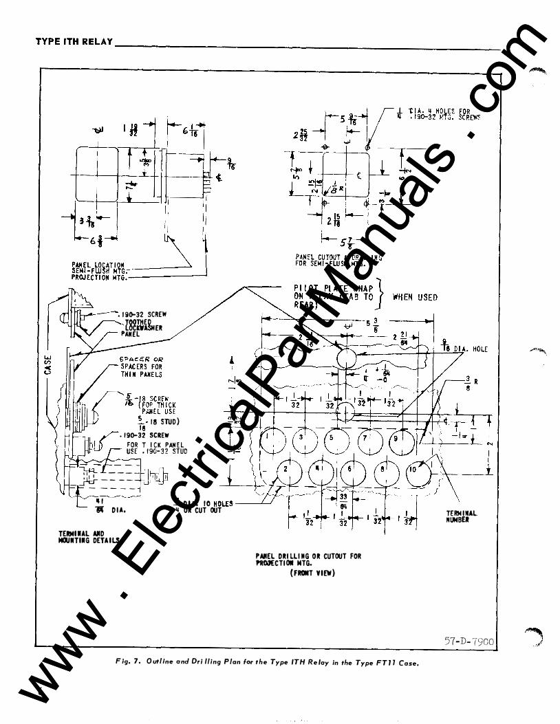
6
' I 9()-32 SCREW
Pl82ml�ER AIIEL
I� - J 8 SCREJ.· '0 { FOP. TH I C K
PAN E L U S E
�8- 1 8 STUD) • 1 9o-32 SCREW
FOR TH I CK PAN E L USE • 1 90- 3 2 STUD
• I l l - - - -
!.f::L� - � = =- - - 1 1 I
1":::- � I - - 3
• D I A - D I A . 1 0 HOLES --�
' .. OR CUT OUT
TERM I Ul AIID MCIUIITIIIG DETAILS
PANEL DRI LLI IIG OR CUTOUT FOR PWOIJECTI OII NTG.
( FROMT VIEW)
F ig. 7. O utll cJ D ne on ri fling P lan lor the Type ITH R I . e oy tn the Type FT 1 7 Case,
TERN I IIAL NUNBU
57-D- 7900
www . El
ectric
alPar
tMan
uals
. com
www . El
ectric
alPar
tMan
uals
. com

www . El
ectric
alPar
tMan
uals
. com
www . El
ectric
alPar
tMan
uals
. com

WESTINGHOUSE E L ECTRIC COR P ORATION RELAY-INSTRUMENT DIVISION NEWARK, N. J.
Printed in U.S.A. www . El
ectric
alPar
tMan
uals
. com
www . El
ectric
alPar
tMan
uals
. com

ADDENDUM TO Westinghouse I .L. 41 -771 F INSTALLATION • OPERATION • MAINTENANCE
I N STRUCT I O N S
TYP E ITH R E LAY
This sheet notes changes which should be made in instruction leaflet I . L. 4 1 -77 1 (SUB F dated May 1 97 5 and earlier Subs).
1 . On Page 5 , l th Unit Acceptance
First sentence should read: "The plunger assembly should pickup within ± 5% and dropout at 90% or higher of the minimum current range stamped on the frame."
ADDEN DUM TO I .L. 41 -771 F EFFECTIVE APRIL 1 977 www . El
ectric
alPar
tMan
uals
. com
www . El
ectric
alPar
tMan
uals
. com

www . El
ectric
alPar
tMan
uals
. com
www . El
ectric
alPar
tMan
uals
. com