installation operation maintenance - amick racinghvac.amickracing.com/rtu training/trane rtu...
TRANSCRIPT

InstallationOperationMaintenance
Packaged Gas/Electric
YC-IOM-1318-EB60D15
December 2004
YC*150D***B*, YCD151C***B*, YCH151C***C*, YC*155B***H*,YC*175C***E*, YC*180B***H*, YC*181C***C*, YC*200B***J*,YC*210C***E*, YC*211C***C*, YC*240B***J*, YC*241C***C*,YC*300B***H*, YC*301C***C*

©American Standard Inc. 2004
Contents
General InformationModel Description ........................... 3Literature Change History ............... 4Overview of Manual ......................... 4Hazard Identification ....................... 5Unit Nameplate ................................ 5Compressor Nameplate .................. 5Unit Description ............................... 5Economizer Control Actuator .......... 6ReliaTel™ Control ........................... 6ReliaTel™ Trane Communication
Interface .................................... 6RLCI - ReliaTel™ LonTalk Communica-
tion Interface (Optional) ............ 6RTOM – ReliaTel™ Options Module
(Optional) .................................. 6System Input Devices & Functions ..6Supply Fan Failure Input (Optional) . 6Clogged Filter Switch (Optional) ..... 6Relative Humidity Sensor (Optional)6Compressor Disable (CPR1/2) ....... 6Low Pressure Control ...................... 7High Pressure Control (Optional) .... 7Power Exhaust Control (Optional) ... 7Lead/Lag Control (Dual Circuit Only)7(BAYSENS006B) ............................. 7(BAYSENS008B) ............................. 7(BAYSENS010B) ............................. 7BAYSENS019B................................ 7(BAYSENS013B) ............................. 7(BAYSENS014B) ............................. 7(BAYSENS016A) ............................. 7(BAYSENS017B) ............................. 8BAYSENS025A Remote sensor for
BAYSTAT036A, 037A. .............. 8High Temperature Sensor
(BAYFRST001A) ....................... 8Evaporator Frost Control ................. 8Smoke Detector Sensor (Optional) . 8Unit Inspection ................................. 9Precautionary Measures ................. 9Storage ............................................ 9
Unit DimensionsInstallation Clearances ..................10Unit/Curb Dimensions ...................11Unit/Curb Dimensions ...................12Horizontal Duct Dimensions .........13
Unit Weight / RiggingRigging and Center-of-Gravity Data14
InstallationFoundation ....................................15Ductwork ........................................15General Unit Requirements ..........16Factory Installed Economizer ........16Electric Heat Requirements ..........16Condensate Drain Configuration ..16Condensate Trap Installation .........16Filter Installation ............................16Main Unit Power ............................17Standard Wiring .............................17Optional TBUE Wiring ....................18Field Installed Control Wiring ........18Control Power Transformer ............18Controls using 24 VAC ..................1824V AC Conductors with Reliatel ..18Controls using DC Analog Input/Outputs .................................19DC Conductors ..............................19Reliatel Conventional ThermostatField Wiring Diagrams ...................19Reliatel Refrigeration Module .......19Smoke Detector .............................20Customer Low Voltage Wiring- ......21Space Temperature Averaging ......22Temperature vs. Resistance ..........22Voltage Imbalance .........................24Electrical Phasing ..........................24Crankcase Heaters (Optional) ......25
Pre - StartTest Modes ..................................... 26Verifying Proper Air Flow ................ 27
Start UpEconomizer Start-Up ...................... 28Compressor Start-Up ..................... 28Scroll Compressors ........................ 28Heating Start-Up ............................ 29
Final System Set UpFinal System Setup ........................30
MaintenanceFan Belt Adjustment .......................31Filters .............................................32Return Air Smoke DetectorMaintenance .................................. 32Cooling Season .............................. 32
Heating Season ............................. 32Final Process ................................. 33Sample Maintenance Log .............. 34
Trouble ShootingReliaTel Control .............................. 35System StatusCheckout Procedure ...................... 35System Failure ............................... 36Cooling Failure ............................... 36Service Failure ............................... 36Simultaneous Heat and CoolFailure ............................................ 36Cool Failure .................................... 36Resetting Cooling and HeatingLockouts ......................................... 36(ZTS) Service Indicator .................. 37Fan Failure Switch .......................... 37(ZTS) Test ....................................... 37(ZTEMP) ........................................ 37Cooling Set Point (CSP)and Heating Set Point (HSP) ......... 37Testingserial communication voltage ......... 38ReliaTel Refrigeration Module(RTRM) Default Chart .................... 38Unit Economizer Control(ECA) Troubleshooting ................... 38ReliaTel Control .............................. 38

3
Model Number Description
Digit 9 - Heating Capacity
L = Low HeatM = Medium HeatH = High Heat
Digit 8 - Electrical Characteristics
3 = 208-230/60/34 = 460/60/3W = 575/60/3
Packaged Gas/Electric Unit Typical Model Nomenclature
Digits 1, 2 - Product Type
YC = Packaged Gas/Electric
Digits 4, 5, 6 - Nominal Gross CoolingCapacity (MBh)
150 = 12½ Ton Standard Efficiency151 = 12½ Ton High Efficiency180 = 15 Ton Standard Efficiency181 = 15 Ton High Efficiency210 = 17½ Ton Standard Efficiency211 = 17½ Ton High Efficiency240 = 20 Ton Standard Efficiency241 = 20 Ton High Efficiency300 = 25 Ton Standard Efficiency301 = 25 Ton High Efficiency
Digit 7- Major Development Sequence
Digit 11- Minor Design Sequence
Y C D 1 5 0 C 3 L 0 A A
1 2 3 4 5 6 7 8 9 10 11 12
Digit 10 - Factory-Installed Options
A = Factory-installed EconomizerB = Oversized MotorC = Downflow Economizer and Oversized MotorF = Trane Communications Interface(TCI)G = Downflow Economizer and TCIH = TXV/Face-Split EvaporatorJ = Oversized Motor and TXV/Face-Split EvaporatorK = Downflow Economizer, Oversized Motor,
and TXV/Face-Split EvaporatorL = Downflow Economizer with TXV/Face-Split EvaporatorM = Reheat CoilN= Downflow Economizer and Reheat CoilP = Oversized Motor and Reheat CoilR = Downflow Economizer, Oversized Motor and Reheat Coil
Digit 12- Service Digit
Digit 3 - Airflow Configuration
D = DownflowH = Horizontal

4
General Information
Literature Change History
YC-IOM-13 (December 2004)Added Dehumidification Option infor-mation.
YC-IOM-13 (April 2003)Reliatel Control System implemented
Overview of Manual
Note: One copy of this documentships inside the control panel of eachunit and is customer property. It mustbe retained by the unit’s maintenancepersonnel.
This booklet describes proper installa-tion, operation, and maintenance proce-dures for air cooled systems. By care-fully reviewing the information within thismanual and following the instructions,the risk of improper operation and/orcomponent damage will be minimized.
It is important that periodic maintenancebe performed to help assure trouble freeoperation. A maintenance schedule isprovided at the end of this manual.Should equipment failure occur, contacta qualified service organization with
qualified, experienced HVAC techni-cians to properly diagnose and repairthis equipment.
Hazard IdentificationWarnings and Cautions appear atappropriate sections throughout this
manual. Read these carefully.
WARNING – Indicates apotentially hazardous situationwhich, if not avoided, could result indeath or serious injury.
CAUTION – Indicates apotentially hazardous situationwhich, if not avoided, may result inminor or moderate injury. It may alsobe used to alert against unsafepractices.
CAUTION – Indicates a situationthat may result in equipment orproperty-damage-only accidents.
Model Number Description
All products are identified by a multiple-character model number that preciselyidentifies a particular type of unit. Anexplanation of the alphanumeric identifi-cation code is provided below. Its usewill enable the owner/operator, install-ing contractors, and service engineersto define the operation, specific compo-nents, and other options for any spe-cific unit.
When ordering replacement parts orrequesting service, be sure to refer tothe specific model number and serialnumber printed on the unit nameplate.

5
General Information
Unit Nameplate
A Mylar unit nameplate is located onthe unit’s corner support next to the fil-ter access panel. It includes the unitmodel number, serial number, electri-cal characteristics, refrigerant charge,as well as other pertinent unit data.
Compressor Nameplate
The nameplate for the compressorsare located on the side of the compres-sor.
Unit Description
Before shipment, each unit is leaktested, dehydrated, charged with re-frigerant and compressor oil, and runtested for proper control operation.
The condenser coils are aluminum fin,mechanically bonded to copper tubing.
Direct-drive, vertical discharge con-denser fans are provided with built-inthermal overload protection.
The ReliaTel™ Control Module is a mi-croelectronic control system that is re-ferred to as “Refrigeration Module”(RTRM). The acronym RTRM is usedextensively throughout this documentwhen referring to the control systemnetwork.
This module through Proportional/Inte-gral control algorithms perform specificunit functions that governs unit opera-tion in response to; zone temperature,supply air temperature, and/or humid-ity conditions depending on the appli-cation. The stages of capacity controlfor these units are achieved by startingand stopping the compressors.
The RTRM is mounted in the controlpanel and is factory wired to the re-spective internal components. TheRTRM receives and interprets informa-tion from other unit modules, sensors,remote panels, and customer binarycontacts to satisfy the applicable re-quest for cooling.
WARNINGContains Refrigerant!
System contains oil and refrigerant under high pressure. Recover refrigerantto relieve pressure before opening the system. See unit nameplate for refrig-erant type. Do not use non-approved refrigerants, refrigerant substitutes, orrefrigerant additives.Failure to follow proper procedures or the use of non-approved refrigerants,refrigerant substitutes, or refrigerant additives could result in death or seri-ous injury or equipment damage.
WARNINGHazardous Voltage w/Capacitors!
Disconnect all electric power, including remote disconnects and discharge allmotor start/run capacitors before servicing. Follow proper lockout/tagout pro-cedures to ensure the power cannot be inadvertently energized. Verify with anappropriate voltmeter that all capacitors have discharged. Failure to discon-nect power and discharge capacitors before servicing could result in death orserious injury.
Note: For additional information regarding the safe discharge of capacitors,see PROD-SVB06A-EN or PROD-SVB06A-FR
CAUTIONEquipment Damage From Ultraviolet (UV) Lights!
The manufacturer does not recommend field installation of ultraviolet lights inits equipment for the intended purpose of improving indoor air quality. High in-tensity C-band ultraviolet light is known to severely damage polymer (plastic)materials and poses a personal safety risk to anyone exposed to the lightwithout proper personal protective equipment. Polymer materials commonlyfound in HVAC equipment that may be susceptible include insulation on elec-trical wiring, fan belts, thermal insulation, various fasteners and bushings.Degradation of these materials can result in serious damage to the equip-ment.
The manufacturer accepts no responsibility for the performance or operationof our equipment in which ultraviolet devices were installed outside of themanufacturer’s factory or its approved suppliers.

6
General Information
Economizer Control ActuatorReliaTel™ ControlThe ECA monitors the mixed air tem-perature, return air temperature, mini-mum position setpoint (local or re-mote), power exhaust setpoint, CO2setpoint, CO2, and ambient dry bulb/enthalpy sensor or comparative humid-ity (return air humidity against ambienthumidity) sensors, if selected, to con-trol dampers to an accuracy of +/- 5%of stroke. The actuator is spring re-turned to the closed position any timethat power is lost to the unit. It is ca-pable of delivering up to 25 inchpounds of torque and is powered by 24VAC.
RTCI -- ReliaTel™ TraneCommunication Interface(Optional)This module is used when the applica-tion calls for an ICSTM building manage-ment type control system. It allows thecontrol and monitoring of the systemthrough an ICS panel. The module canbe ordered from the factory or orderedas a kit to be field installed. Follow theinstallation instruction that ships witheach kit when field installation is neces-sary.
RLCI - ReliaTel™ LonTalkCommunication Interface(Optional)This module is used when the applica-tion calls for an ICSTM building manage-ment type control system that isLonTalk. It allows the control and moni-toring of the system through an ICSpanel. The module can be orderedfrom the factory or ordered as a kit tobe field installed. Follow the installa-tion instruction that ships with each kitwhen field installation is necessary.
RTOM – ReliaTel™ OptionsModule (Optional)The RTOM monitors the supply fanproving, clogged filter, supply air tem-perature, exhaust fan setpoint, supplyair tempering, Frostat™ and smoke de-tector. Refer to system input devicesand functions for operation.
Clogged Filter Switch (Optional)The unit mounted clogged filter switchmonitors the pressure differentialacross the return air filters. It ismounted in the filter section and isconnected to the RTOM. A diagnosticSERVICE signal is sent to the remotepanel if the pressure differential acrossthe filters is at least 0.5" w.c. The con-tacts will automatically open when thepressure differential across the filtersdecreases to approximately 0.4" w.c.The clogged filter output is energizedwhen the supply fan is operating andthe clogged filter switch has beenclosed for at least 2 minutes. The sys-tem will continue to operate regardlessof the status of the filter switch.
Compressor Disable (CPR1/2)This input incorporates the low pres-sure control (LPC) of each refrigerationcircuit and can be activated by openinga field supplied contact installed on theLTB.
If this circuit is open before the com-pressor is started, the compressor willnot be allowed to operate. Anytime thiscircuit is opened for 1 continuous sec-ond during compressor operation, thecompressor for that circuit is immedi-ately turned “Off”. The compressor willnot be allowed to restart for a minimumof 3 minutes should the contacts close.
If four consecutive open conditions oc-cur during the first three minutes of op-eration, the compressor for that circuitwill be locked out, a diagnostic commu-nicated to the remote panel (if in-stalled), and a manual reset will be re-quired to restart the compressor.
System Input Devices &Functions
The RTRM must have a zone sensor orthermostat input in order to operate theunit. The flexibility of having severalmode capabilities depends upon thetype of zone sensor or thermostat se-lected to interface with the RTRM.
The descriptions of the following basicInput Devices used within the RTRMnetwork are to acquaint the operatorwith their function as they interface withthe various modules. Refer to the unit’selectrical schematic for the specificmodule connections.
The following controls are availablefrom the factory for field installation.
Supply Fan Failure Input (Optional)The Fan Failure Switch can be con-nected to sense indoor fan operation:
FFS (Fan Failure Switch) If air flowthrough the unit is not proven by the dif-ferential pressure switch connected tothe RTOM (factory set point 0.07 “ w.c.)within 40 seconds nominally, the RTRMwill shut off all mechanical operations,lock the system out, send a diagnosticto ICS, and the SERVICE output willflash. The system will remain locked outuntil a reset is initiated either manuallyor through ICS.
Wall Mounted Relative HumiditySensor (BAYSENS036A)Field installed, wall mounted humiditysensor is used to control activation ofthe hot gas reheat dehumidification op-tion. Humidity set points can be se-lected for relative humidity levels be-tween 40% and 60% by adjusting theDEHUMID setting on the ReliaTel Op-tions Module. See page 19.
Duct Mounted Relative HumiditySensor (BAYSENS037A)Field installed, duct mounted humiditysensor is used to control activation ofthe hot gas reheat dehumidification op-tion. Humidity set points can be se-lected for relative humidity levels be-tween 40% and 60% by adjusting theDEHUMID setting on the ReliaTel Op-tions Module. See page 19.

7
General Information
Low Pressure Control
ReliaTel ControlWhen the LPC is opened for 1 continu-ous second, the compressor for that cir-cuit is turned off immediately. The com-pressor will not be allowed to restart fora minimum of 3 minutes.
If four consecutive open conditions oc-cur during the first three minutes of op-eration, the compressor will be lockedout, a diagnostic communicated toICSTM if applicable, and a manual resetwill be required to restart the compres-sor.
High Pressure Control (Optional)ReliaTel ControlThe high pressure controls are wired inseries between the compressor outputson the RTRM and the compressorcontactor coils. If the high pressurecontrol switch opens, the RTRMsenses a lack of current while callingfor cooling and locks the compressorout.
On dual circuit units, if the high pres-sure control opens, the compressor onthe affected circuit is locked out. Amanual reset for the affected circuit isrequired.
Power Exhaust Control (Optional)The power exhaust fan is started when-ever the position of the economizerdampers meets or exceed the powerexhaust setpoint when the indoor fan ison.
The setpoint panel is located in the re-turn air section and is factory set at25%.
Lead/Lag Control (Dual Circuit Only)Lead/Lag is a selectable input locatedon the RTRM. The RTRM is configuredfrom the factory with the Lead/Lag con-trol disabled. To activate the Lead/Lagfunction, simply cut the wire connectedto J3-8 at the RTRM. When it is acti-vated, each time the designated leadcompressor is shut off due to the loadbeing satisfied, the lead compressor orrefrigeration circuit switches. When theRTRM is powered up, i.e. after a powerfailure, the control will default to thenumber one circuit compressor.
Zone Sensor Module (ZSM)(BAYSENS006B)This electronic sensor features threesystem switch settings (Heat, Cool,and Off) and two fan settings (On andAuto). It is a manual changeover controlwith single setpoint. (Cooling SetpointOnly)
Zone Sensor Module (ZSM)(BAYSENS008B)This electronic sensor features foursystem switch settings (Heat, Cool,Auto, and Off) and two fan settings (Onand Auto). It is a manual or autochangeover control with dual setpointcapability. It can be used with a remotezone temperature sensorBAYSENS017B.
Zone Sensor (BAYSENS010B)This electronic sensor features foursystem switch settings (Heat, Cool,Auto, and Off) and two fan settings (Onand Auto) with four system statusLED’s. It is a manual or autochangeover control with dual setpointcapability. It can be used with a remotezone temperature sensorBAYSENS017B.
Programmable Zone Sensor -BAYSENS019BThis 7 day programmable sensor fea-tures 2, 3 or 4 periods for Occupied orUnoccupied programming per day. If thepower is interrupted, the program is re-tained in permanent memory. If poweris off for an extended period of time,only the clock and day may have to bereset.
The Zone Sensor allows selection of 2,3 or 4 system modes (Heat, Cool, Auto,and Off), two fan modes (On and Auto).It has dual temperature selection withprogrammable start time capability.
The occupied cooling set point rangesbetween 45 and 98 degrees Fahrenheit.The heating set point ranges between43 and 96 degrees Fahrenheit.
A liquid crystal display (LCD) displayszone temperature, temperature setpoints, day of the week, time, and op-erational mode symbols.
The Option Menu is used to enable ordisable applicable functions, i.e.; Morn-ing Warm-up, Economizer minimum po-sition override during unoccupied sta-tus, Fahrenheit or Centigrade, Supplyair tempering, Remote zone tempera-ture sensor, 12/24 hour time display,Smart fan, and Computed recovery.
Remote Zone Sensor(BAYSENS013B)This electronic sensor features remotezone sensing and timed override withoverride cancellation. It is used with aTrane Integrated ComfortTM
buildingmanagement system.
Remote Zone Sensor(BAYSENS014B)This electronic sensor features singlesetpoint capability and timed overridewith override cancellation. It is usedwith a Trane Integrated ComfortTM
building management system.

8
Remote Zone Sensor(BAYSENS016A)This bullet type temperature sensor canbe used for; outside air (ambient) sens-ing, return air temperature sensing,supply air temperature sensing, remotetemperature sensing (uncovered. Wiringprocedures vary according to the par-ticular application and equipment in-volved. Refer to the unit’s wiring dia-grams for proper connections.
Remote Zone Sensor(BAYSENS017B)This electronic sensor can be used withBAYSENS006B, 008B, 010B, 019B Re-mote Panels. When this sensor is wiredto a BAYSENS019B Remote Panel, wir-ing must be 18 AWG Shielded TwistedPair (Belden 8760 or equivalent). Referto the specific Remote Panel for wiringdetails.
BAYSTAT036ASingle Stage - 1 Heat/1 Cool
BAYSTAT037AMulti Stage - 2 Heat/2 Cool - Can beUsed for Economizer Operation
BAYSENS025A Remote sensor forBAYSTAT036A, 037A.
High Temperature Sensor(BAYFRST003A)This sensor connects to the RTRMEmergency Stop Input on the LTB andprovides high limit “shutdown” of theunit. The sensor is used to detect hightemperatures due to fire in the air con-ditioning or ventilation ducts. The sen-sor is designed to mount directly to thesheet metal duct. Each kit contains twosensors. The return air duct sensor(X1310004001) is set to open at 135°F.The supply air duct sensor(X1310004002) is set to open at 240°F.The control can be reset after the tem-perature has been lowered approxi-mately 25°F below the cutout setpoint.
Evaporator Frost ControlThis input incorporates the Frostat™control (FOS) mounted in the indoorcoil and can be activated by closing afield supplied contact installed in paral-lel with the FOS.
If this circuit is open before the com-pressor is started, the compressor willnot be allowed to operate. Anytime thiscircuit is opened for 5 continuous sec-onds during compressor operation, thecompressor for that circuit is immedi-ately turned “Off”. The compressor willnot be allowed to restart for a minimumof 3 minutes should the FOS close.
Smoke Detector Sensor (Optional)This sensor is only applicable on unitsequipped with a RTOM. It provides highlimit “shutdown” of the unit and requiresa manual reset. The sensor is used todetect smoke due to fire in the air con-ditioning or ventilation ducts.
Important: The supply and return airsmoke detectors are designed toshut off the unit if smoke is sensed inthe supply air stream or return airstream. This function is performed bysampling the airflow entering the unitat the return air opening. Follow theinstructions provided below toassure that the airflow through theunit is sufficient for adequatesampling. Failure to follow theseinstructions will prevent the smokedetectors from performing it's designfunction.
Important: Airflow through the unit isaffected by the amount of dirt anddebris accumulated on the indoorcoil and filters. To insure that airflowthrough the unit is adequate forproper sampling by the return airsmoke detector, complete adherenceto the maintenance procedures,including recommended intervalsbetween filter changes, and coilcleaning is required.
Important: Periodic checks andmaintenance procedures must beperformed on the smoke detector toinsure that it will function properly.For detailed instructions concerningthese checks and procedures, refer tothe appropriate section(s) of thesmoke detector Installation andMaintenance Instructions providedwith the literature package for thisunit.
In order for the supply air smoke detec-tor or return air smoke detector to prop-erly sense smoke in the supply airstream or return air stream, the air ve-locity entering the smoke detector unitmust be between 500 and 4000 feet perminute. Equipment covered in thismanual will develop an airflow velocitythat falls within these limits over the en-tire airflow range specified in the evapo-rator fan performance tables.
There are certain models, however, ifoperated at low airflow, will not developan airflow velocity that falls within therequired 500 to 4000 feet per minuterange. For these models, the design air-flow shall be greater than or equalto theminimum CFM specifedin the table pro-vided below. Failure to follow these in-structions will prevent the smoke detec-tor from performing it’s design function.
Unit Model Minimum Allowable Airflow Number with
Return Air Smoke Detector
YCD181 5300 CFM
General Information

9
Unit Inspection
As soon as the unit arrives at the jobsite:
[ ] Verify that the nameplate datamatches the data on the sales orderand bill of lading (including electricaldata).
[ ] Verify that the power supply complieswith the unit nameplate specifica-tions.
[ ] Visually inspect the exterior of theunit, including the roof, for signs ofshipping damage.
[ ] Visually inspect the internal compo-nents for shipping damage as soonas possible after delivery and beforeit is stored. Do not walk on the sheetmetal base pans.
[ ] If concealed damage is discovered,notify the carrier’s terminal of dam-age immediately by phone and bymail. Concealed damage must be re-ported within 15 days.
Request an immediate joint inspec-tion of the damage by the carrier andthe consignee. Do not remove dam-aged material from the receiving lo-cation. Take photos of the damage, ifpossible. The owner must providereasonable evidence that the dam-age did not occur after delivery.
[ ] Notify the appropriate sales repre-sentative before installing or repair-ing a damaged unit.
WARNINGFiberglass WoolProduct contains fiberglass wool.Disturbing the insulation in thisproduct during installation, mainte-nance or repair will expose you toairborne particles of glass wool fi-bers and ceramic fibers known to thestate of California to cause cancerthrough inhalation. Glass wool fibersmay also cause respiratory, skin oreye irritation.
Precautionary Measures
· Avoid breathing fiberglass dust.
· Use a NIOSH approved dust/mistrespirator.
· Avoid contact with the skin oreyes. Wear long-sleeved, loose-fit-ting clothing, gloves, and eye pro-tection.
· Wash clothes separately fromother clothing: rinse washer thor-oughly.
· Operations such as sawing, blow-ing, tear-out, and spray-ing may generate fiber concentra-tions requiring additionalrespiratory protection. Usethe appropriate NIOSH approvedrespiration in these situa-tions.
First Aid Measures
Eye Contact - Flush eyes with water toremove dust. If symptoms persist,seek medical attention.
Skin Contact - Wash affected areasgently with soap and warm waterafter handling.
Storage
Take precautions to prevent condensatefrom forming inside the unit’s electricalcompartments and motors if:
a. the unit is stored before it is installed;or,
b. the unit is set on the roof curb, andtemporary heat is provided in thebuilding. Isolate all side panel ser-vice entrances and base pan open-ings (e.g., conduit holes, S/A and R/A openings, and flue openings) fromthe ambient air until the unit is readyfor start-up.
Note: Do not use the unit’s heater fortemporary heat without firstcompleting the start-up proceduredetailed under “Starting the Unit”.
The manufacturer will not assume anyresponsibility for equipment damage re-sulting from condensate accumulationon the unit’s electrical and/or mechani-cal components.
Unit ClearancesFigure 1 illustrates the minimum operat-ing and service clearances for either asingle or multiple unit installation. Theseclearances are the minimum distancesnecessary to assure adequate service-ability, cataloged unit capacity, andpeak operating efficiency.
Providing less than the recommendedclearances may result in condenser coilstarvation, “short-circuiting” of exhaustand economizer airflows, or recircula-tion of hot condenser air.
General nformation

10
Unit Dimensions
Figure 1Typical Installation Clearances for Single & Multiple Unit Applications

11
Unit / Curb Dimensions
Figure 2Unit Dimensional Data12 1/2 Ton, 15 Ton, 171/2 Ton Standard Efficiency12 1/2 Ton High Efficiency
Roof Curb Dimensional Data12 1/2 Ton, 15 Ton, 171/2 Ton Standard Efficiency12 1/2 Ton High Efficiency

12
Figure 3Unit Dimensional Data20 Ton, 25 Ton Standard Efficiency15 - 25 Tons High Efficiency
Roofcurb Dimensional Data20 Ton, 25 Ton Standard Efficiency15 - 25 Tons High Efficiency
Unit / Curb Dimensions

13
Horizontal Duct Dimensions
Figure 4Horizontal Duct Dimensional Data12 1/2 Ton, 15 Ton, 171/2 Ton Standard Efficiency12 1/2 Ton High Efficiency
Figure 5Horizontal Duct Dimensional Data20 Ton, 25 Ton Standard Efficiency15 - 25 Tons High Efficiency

14
Unit Weight / Rigging
Table 1Typical Unit Weights & Point Loading Data
Unit Net Corner Wts. (lbs) Unit Net Corner Wts. (kg)Models Weight (lbs) A B C D Models Weight (kg) A B C D
YC*150D 1458 495 373 254 336 YC*150D 661 225 169 115 152YC*151C 1547 523 383 271 370 YC*151C 702 237 174 123 168YC*155B 1539 536 388 266 357 YC*155B 698 243 176 121 162YC*180B 1665 600 395 266 404 YC*180B 755 272 179 121 183YC*181C 2005 686 504 345 470 YC*181C 909 311 229 156 213YC*175C 1620 553 414 280 373 YC*175C 735 251 188 127 169YC*210C 1821 618 463 317 424 YC*210C 826 280 210 144 192YC*211C 2088 701 538 369 480 YC*211C 947 318 244 167 218YC*200B 2028 714 534 333 448 YC*200B 920 324 242 151 203YC*240B 2088 738 526 343 481 YC*240B 947 335 239 156 218YC*241C 2186 751 568 373 494 YC*241C 992 341 258 169 224YC*250B 2082 721 552 351 458 YC*250B 944 327 250 159 208YC*300B 2086 721 553 351 459 YC*300B 946 327 251 159 208YC*301C 2191 755 569 373 495 YC*301C 994 342 258 169 225* Downflow or Horizontal * Downflow or HorizontalNote: Corner weights are given for information only.Unit is to be supported continuously by a curb or equivalent frame support.
Figure 6Rigging and Center-of-Gravity Data
WARNINGHeavy Objects!
Do not use cables (chains or slings) except as shown.Each of the cables (chains or slings) used to lift the unitmust be capable of supporting the entire weight of theunit. Lifting cables (chains or slings) may not be of thesame length. Adjust as necessary for even unit lift. Otherlifting arrangements may cause equipment or property-only damage. Failure to properly lift unit may result indeath or serious injury. See details below.
WARNINGImproper Unit Lift!
Test lift unit approximately 24 inches to verify propercenter of gravity lift point. To avoid dropping of unit, re-position lifting point if unit is not level. Failure to prop-erly lift unit could result in death or serious injury or pos-sible equipment or property-only damage.
RiggingRefer to Figure 6 and Table 1 for typical unit operating weightsriffing before proceeding.
1. Remove the shipping crate from around the unit. Do not re-move the crating from the top of the unit.
2. Rig the unit as shown in Figure 6. Attach adequatestrength lifting slings to all four lifting brackets in the unitbase rail. Do not use cables, chains, or slings except asshown.
3. Install a lifting bar, as shown in Figure 6, to protect the unitand to facilitate a uniform lift. The minimum distance be-tween the lifting hook and the top of the unit should be 7feet.
4. Test-lift the unit to ensure it is properly rigged and bal-anced, make any necessary rigging adjustments.
5. Lift the unit and position it into place.
6. Downflow units; align the base rail of the unit with the curbrail while lowering the unit onto the curb. Make sure thatthe gasket on the curb is not damaged while positioningthe unit.

15
Installation
Foundation
Horizontal UnitsIf the unit is installed at ground level,elevate it above the snow line. Provideconcrete footings at each support loca-tion with a “full perimeter” supportstructure or a slab foundation for sup-port. Refer to Table 1 for the unit’s oper-ating and point loading weights whenconstructing a footing foundation.
If anchoring is required, anchor theunit to the slab using hold down boltsor isolators. Isolators should be in-stalled to minimize the transmission ofvibrations into the building.
For rooftop applications, ensure theroof is strong enough to support thecombined unit and support structuralweight. Refer to Table 1 for the unit op-erating weights. If anchoring is re-quired, anchor the unit to the roof withhold-down bolts or isolators.
Check with a roofing contractor forproper waterproofing procedures.
Ductwork
Elbows with turning vanes or splittersare recommended to minimize airnoise due to turbulence and to reducestatic pressure.
When attaching the ductwork to theunit, provide a water- tight flexible con-nector at the unit to prevent operatingsounds from transmitting through theductwork.
All outdoor ductwork between the unitand the structure should be weatherproofed after installation is completed.
Note: For sound consideration, cutonly the holes in the roof deck for theductwork penetrations. Do not cutout the entire roof deck within thecurb perimeter.
If a Curb Accessory Kit is not used:
a. The ductwork can be attacheddirectly to the factory-providedflanges around the unit’s supplyand return air openings. Be sureto use flexible duct connectionsat the unit.
b. For “built-up” curbs supplied byothers, gaskets must be installedaround the curb perimeterflange and the supply and returnair opening flanges.

16
Installation
General Unit Requirements
The checklist listed below is a sum-mary of the steps required to success-fully install a commercial unit. Thischecklist is intended to acquaint the in-stalling personnel with what is re-quired in the installation process. Itdoes not replace the detailed instruc-tions called out in the applicable sec-tions of this manual.
[ ] Check the unit for shipping damageand material shortage; file a freightclaim and notify appropriate salesrepresentative.
[ ] Verify correct model, options andvoltage from nameplate.
[ ] Verify that the installation location ofthe unit will provide the requiredclearance for proper operation.
[ ] Assemble and install the roof curb (ifapplicable). Refer to the latest editionof the curb installers guide that shipswith each curb kit.
[ ] Fabricate and install ductwork; se-cure ductwork to curb.
[ ] Rigging the unit.
[ ] Set the unit onto the curb; check forlevelness.
[ ] Ensure unit-to-curb seal is tight andwithout buckles or cracks.
[ ] Install and connect a condensatedrain line to the evaporator drainconnection.
Factory Installed Economizer
[ ] Ensure the economizer has beenpulled out into the operating position.Refer to the economizer installersguide for proper position and setup.
[ ] Install all access panels.
Main Electrical Power Requirements
[ ] Verify that the power supply complieswith the unit nameplate specifica-tions.
[ ] Inspect all control panel components;tighten any loose connections.
[ ] Connect properly sized and pro-tected power supply wiring to a field-supplied/installed disconnect switchand to the main power terminal block(HTB1) in the unit control panel.
[ ] Install proper grounding wires to anearth ground.
Note: All field-installed wiring mustcomply with NEC and applicable localcodes.
Electric Heat Requirements
[ ] Verify that the power supply complieswith the electric heater specificationson the unit and heater nameplate.
[ ] Inspect the heater junction box andcontrol panel; tighten any loose con-nections.
[ ] Check electric heat circuits for conti-nuity.
Low Voltage Wiring (AC & DC) Require-ments
[ ] Install the zone thermostat, with orwithout switching subbase.
[ ] Connect properly sized control wiringto the proper termination points be-tween the zone thermostat and theunit control panel.
Condensate Drain Configuration
An evaporator condensate drain con-nection is provided on each unit. Referto Figures 2, 3, 4 or 5 for the appropri-ate drain location.
A condensate trap must be installed atthe unit due to the drain connection be-ing on the “negative pressure” side ofthe fan. Install the P-Trap using theguidelines in Figure 7.
A condensate drain line must be con-nected to the P-Trap. Pitch the drainlines at least 1/2 inch for every 10 feetof horizontal run to assure proper con-densate flow. Do not allow the horizon-tal run to sag causing a possibledouble-trap condition which could resultin condensate backup due to “air lock”.
Figure 7Condensate Trap Installation
Filter Installation
Each unit ships with 2 inch filters in-stalled. The quantity of filters is deter-mined by unit size. Access to the filtersis obtained by removing the indoor fanaccess panel.
Refer to the unit Service Facts(shipped with each unit) for filter re-quirements.
Note: Do not operate the unit withoutfilters.

17
Installation
Field Installed Power WiringAn overall dimensional layout for thestandard field installed wiring entranceinto the unit is illustrated in Figures2,and 3. To insure that the unit’s supplypower wiring is properly sized and in-stalled, follow the guidelines outlinedbelow.
Note: All field installed wiring mustconform to NEC guidelines as well asState and Local codes.
Verify that the power supply available iscompatible with the unit’s nameplateratings. The available supply powermust be within 10% of the rated voltagestamped on the nameplate. Use onlycopper conductors to connect thepower supply to the unit.
CAUTIONUse Copper ConductorsOnly!
Unit terminals are not designed toaccept other types of conductors.Failure to use copper conductorsmay result in equipment damage.
Failure to do so may cause damage tothe equipment.
Note: If the unit is not equipped withan optional factory installednonfused disconnect switch or circuitbreaker, a field supplied disconnectswitch must be installed at or nearthe unit in accordance with theNational Electrical Code (NEC latestedition).
Main Unit PowerStandard Wiring
The electrical service must be protectedfrom over current and short circuit condi-tions in accordance with NEC require-ments. Protection devices must be sizedaccording to the electrical data on thenameplate.
1. If the unit is not equipped with an op-tional factory installed nonfused dis-connect switch or circuit breaker, afield supplied disconnect switch mustbe installed at or near the unit in ac-cordance with the National ElectricalCode (NEC latest edition).
2. Location of the applicable electricalservice entrance is illustrated in Fig-ures 2 or 3. Complete the unit’spower wiring connections onto ei-ther; the main terminal block HTB1inside the unit control panel, the fac-tory mounted nonfused disconnectswitch (UCD) or circuit breaker(UCB), or the electric heat terminalblock. Refer to the customer connec-tion diagram that shipped with theunit for specific termination points.
3. Provide proper grounding for the unitin accordance with local and nationalcodes.

18
Installation
Main Unit PowerOptional TBUE Wiring(Through the Base Electrical Option)
1. Location of the applicable electrical service is illustratedbelow. Refer to the customer connection diagram that isshipped with the unit for specific termination points. Thetermination points, depending on the customer option se-lected would be a factory mounted nonfused disconnectswitch (UDC) or circuit breaker (UCB).
2. Provide proper grounding for the unit in accordance with lo-cal and national codes.
Field Installed Control Wiring
An overall layout of the various control options available withthe required number of conductors for each control device isillustrated in Figure 8.
Note: All field wiring must conform to NEC guidelines aswell as state and local codes.
Control Power Transformer
The 24 volt control power transformers are to be used onlywith the accessories called out in this manual. Transformersrated greater than 50 VA are equipped with internal circuitbreakers. If a circuit breaker trips, turn “Off” all power to theunit before attempting to reset it.
WARNINGHazardous Voltage!
Disconnect all electric power, including remote discon-nects before servicing. Follow proper lockout/tagout pro-cedures to ensure the power can not be inadvertently en-ergized. Failure to disconnect power before servicingcould result in death or serious injury.
Failure to disconnect power before servicing can cause se-vere personal injury or death.
The transformer is located in the control panel. The circuitbreaker is located on the left side of the transformer and canbe reset by pressing in on the black reset button.
Controls using 24 VAC
Before installing any connecting wiring, refer to Figure 2 or 3for the electrical access locations provided on the unit andTable 2 for AC conductor sizing guidelines, and;
a. Use copper conductors unless otherwise specified.
b. Ensure that the AC control wiring between the controls andthe unit’s termination point does not exceed three (3)ohms/conductor for the length of the run.
Note: Resistance in excess of 3 ohms per conductor maycause component failure due to insufficient AC voltagesupply.
c. Be sure to check all loads and conductors for grounds,shorts, and mis-wiring.
d. Do not run the AC low voltage wiring in the same conduitwith the high voltage power wiring.
e. Route low voltage wiring per illustrations on page 19.
Table 2 - Electromechanical Thermostat24V AC Conductors with Reliatel
Distance from Unit Recommendedto Control Wire Size
000 - 460 feet 18 gauge
000 - 140 m .75 mm2
461 - 732 feet 16 gauge

19
Installation
Controls using DC Analog Input/Outputs(Standard Low Voltage Multiconductor Wire)
Before installing any connecting wiring between the unit andcomponents utilizing a DC analog input\output signal, refer toFigure 2 or 3 for the electrical access locations provided onthe unit.
a. Table 3 lists the conductor sizing guidelines that must befollowed when interconnecting the DC binary output de-vices and the system components utilizing a DC analoginput\output signal to the unit.
Note: Resistance in excess of 2.5 ohms per conductor cancause deviations in the accuracy of the controls.
b. Ensure that the wiring between controls and the unit’s ter-mination point does not exceed two and a half (2.5) ohms/conductor for the length of the run.
c. Do not run the electrical wires transporting DC signals in oraround conduit housing high voltage wires.
DC ConductorsTable 3Zone Sensor Module wiring
Distance from RecommendedUnit to Control Wire Size
0 - 150 feet 22 gauge0 - 45.7 m .33 mm2
151 - 240 feet 20 gauge46 - 73.1 m .50 mm2
241 -385 feet 18 gauge
ReliaTel Options Module
Reliatel Conventional Thermostat Field WiringDiagrams
RTRM
ReliaTel Relative Humidity Sensor(Dehumidification Option)
ReliaTel Humidistat(Dehumidification Option)

20
Installation
Smoke DetectorCustomer Low Voltage Wiring-
When interlocking System Sensorsmoke detectors together, all of the de-tectors must be powered from thesame power supply. If multiple smokedetectors are required, all detectorsmust be disconnected from the HVACunit power supply and connected to-gether from another single source sup-ply.
Note: Do not interconnect smokedetectors together that haveseparate power supplies. Do notexceed ten smoke detectors on onepower supply.
Note: Multiple System Sensor smokedetectors are connected togetherusing terminals 1 and 12 on eachdetector.
If you have supply and return smokedetectors in all HVAC units, you canconnect a maximum of 5 HVAC units(10 detectors) up to one power supply.See the following field wiring examplebelow.
If you have more than 5 HVAC units,you can connect all the supplie detec-tors together on one power supply (upto 10 HVAC units), and all the returndetectors together (up to 10 HVACunits) on another power supply. See thefollowing field wiring example below.

21
Installation
Figure 8Typical Field Wiring Diagrams for Optional Controls (ReliaTel™ only)

22
Installation
Space Temperature Averaging
Space temperature averaging is accomplished by wiring a number of remote sensors in a series/parallel circuit.
Using the BAYSENS016* or BAYSENS017*, at least four sensors are required to accomplish space temperature aver-aging. Example #1 illustrates two series circuits with two sensors in each circiut wired in parallel. The square of anynumber of remote sensors is required. Example #2 illustrates three sensors squared in a series/parallel circuit. UsingBAYSENS032*, two sensors are required to accomplish space temperature averaging. Example #3 illustrates the cir-cuit required for this senor. Table 4 lists the temperature versus resistance coefficient for all sensing
Table 4Temperature vs. Resistance
Degrees F°
Degrees C°
Nominal Resistance
-20° -28.9° 170.1 K - Ohms-15° -26.1° 143.5 K - Ohms-10° -23.3° 121.4 K - Ohms -5° -20.6° 103.0 K - Ohms 0° -17.8° 87.56 K - Ohms 5° -15.0° 74.65 K - Ohms
10° -12.2° 63.80 K - Ohms 15° -9.4° 54.66 K - Ohms20° -6.7° 46.94 K - Ohms25° -3.8° 40.40 K - Ohms30° -1.1° 34.85 K - Ohms35° 1.7° 30.18 K - Ohms40° 4.4° 26.22 K - Ohms45° 7.2° 22.85 K - Ohms50° 10.0° 19.96 K - Ohms55° 12.8° 17.47 K - Ohms60° 15.6° 15.33 K - Ohms65° 18.3° 13.49 K - Ohms70° 21.1° 11.89 K - Ohms75° 23.9° 10.50 K - Ohms80° 26.7° 9.297 K - Ohms85° 29.4° 8.247 K - Ohms90° 32.2° 7.330 K - Ohms95° 35.0° 6.528 K - Ohms
100° 37.8° 5.824 K - Ohms
Temperature

23
Installation
Gas Heater Operating DataHeating Input Rate – BTUH 3 135,000 205,000Minimum Supply Gas Pressur Natural/ LP 3.5” w.c./ 8.0” w.c.Manifold Gas Pressure (See Note 1) -0.2” w.cCombustion Blower Suction Pressure (1st Stage) -2.1 to -3.1” w.c. -0.8 to -1.2” w.c. (With Gas Valve Closed) (2nd Stage) N/A -2.1 to -3.1” w.c.Minimum Flame Sensing Current (See Note 2) 5.0 Microamps D.C.Normal Sensing Current Range 8.0 to 16.0 Microamps D.C.Flue Gas Temperature Rise Above Ambient 400 to 500 F 350 to 475 FFlue Gas Content - %CO2 Natural 8.3 to 9.5 8.0 to 9.0
LP 9.5 to 10.5Minimum Supply Air Temperature Across Heat Exchanger 40 FNotes:1. This Unit has a negative pressure gas valve. Never adjust to a positive pressure.2. A voltage reading across pens (V+) & (V-) is equatable to the flame sensing current. One volt equals one micro amp. 3. For 50 Hertz applications, multiply rated BTUH by 83 percent.
Schematic Diagram for Field Gas Piping to Unit
Iron Pipe Size (IPS) Inches Length of 1/2" 3/4" 1" 1 1/4" 1 1/2" Pipe (Ft.) Pipe Pipe Pipe Pipe Pipe
15 76 176 345 750 122030 52 120 241 535 85045 43 99 199 435 70060 38 86 173 380 61075 77 155 345 545
Capacity of Pipe of Different Diameters andLengths in Cu. Ft. Per Hr. with PressureDrop of 0.3" and Specific Gravity of 0.60
Specific Gravity MultipliersSpecificGravity Multiplier
0.50 1.10 0.55 1.040.60 1.000.65 0.96
Typical Unit Gas Train Configuration
24
Installation
Use the checklist provided below inconjunction with the “General Unit Re-quirements” checklist to ensure thatthe unit is properly installed and readyfor operation.
WARNINGHazardous Voltage!
Disconnect all electric power, includ-ing remote disconnects before ser-vicing. Follow proper lockout/tagoutprocedures to ensure the power cannot be inadvertently energized. Fail-ure to disconnect power before ser-vicing could result in death or seri-ous injury.
Failure to disconnect power before ser-vicing can cause severe personal in-jury or death.
[ ] Check all electrical connections fortightness and “point of termination”accuracy.
[ ] Verify that the condenser airflow willbe unobstructed.
[ ] Verify that the condenser fan and in-door blower turn freely without rub-bing and are properly tightened onthe shafts.
[ ] Check the supply fan belts for propertension and the fan bearings for suf-ficient lubrication. If the belts requireadjustment, or if the bearings needlubricating, refer to the maintenancesection of this manual for instruc-tions.
[ ] Verify that a condensate trap is in-stalled and the piping is properlysized and pitched.
[ ] Verify that the correct size and num-ber of filters are in place.
[ ] Inspect the interior of the unit fortools and debris and install all panelsin preparation for starting the unit.
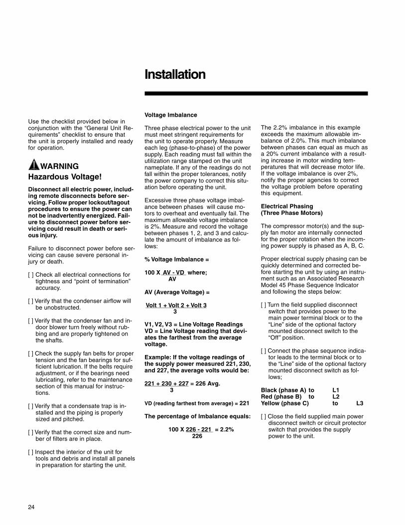
Voltage Imbalance
Three phase electrical power to the unitmust meet stringent requirements forthe unit to operate properly. Measureeach leg (phase-to-phase) of the powersupply. Each reading must fall within theutilization range stamped on the unitnameplate. If any of the readings do notfall within the proper tolerances, notifythe power company to correct this situ-ation before operating the unit.
Excessive three phase voltage imbal-ance between phases will cause mo-tors to overheat and eventually fail. Themaximum allowable voltage imbalanceis 2%. Measure and record the voltagebetween phases 1, 2, and 3 and calcu-late the amount of imbalance as fol-lows:
% Voltage Imbalance =
100 X AV - VD where;AV
AV (Average Voltage) =
Volt 1 + Volt 2 + Volt 3 3
V1, V2, V3 = Line Voltage ReadingsVD = Line Voltage reading that devi-ates the farthest from the averagevoltage.
Example: If the voltage readings ofthe supply power measured 221, 230,and 227, the average volts would be:
221 + 230 + 227 = 226 Avg. 3
VD (reading farthest from average) = 221
The percentage of Imbalance equals:
100 X 226 - 221 = 2.2%226
The 2.2% imbalance in this exampleexceeds the maximum allowable im-balance of 2.0%. This much imbalancebetween phases can equal as much asa 20% current imbalance with a result-ing increase in motor winding tem-peratures that will decrease motor life.If the voltage imbalance is over 2%,notify the proper agencies to correctthe voltage problem before operatingthis equipment.
Electrical Phasing(Three Phase Motors)
The compressor motor(s) and the sup-ply fan motor are internally connectedfor the proper rotation when the incom-ing power supply is phased as A, B, C.
Proper electrical supply phasing can bequickly determined and corrected be-fore starting the unit by using an instru-ment such as an Associated ResearchModel 45 Phase Sequence Indicatorand following the steps below:
[ ] Turn the field supplied disconnectswitch that provides power to themain power terminal block or to the“Line” side of the optional factorymounted disconnect switch to the“Off” position.
[ ] Connect the phase sequence indica-tor leads to the terminal block or tothe “Line” side of the optional factorymounted disconnect switch as fol-lows;
Black (phase A) to L1Red (phase B) to L2Yellow (phase C) to L3
[ ] Close the field supplied main powerdisconnect switch or circuit protectorswitch that provides the supplypower to the unit.

25
Installation
WARNINGLive Electrical Components!
During installation, testing, servicingand troubleshooting of this product,it may be necessary to work with liveelectrical components. Have a quali-fied licensed electrician or other in-dividual who has been properlytrained in handling live electricalcomponents perform these tasks.Failure to follow all electrical safetyprecautions when exposed to liveelectrical components could result indeath or serious injury.
To prevent injury or death from electro-cution, it is the responsibility of thetechnician to recognize this hazard anduse extreme care when performing ser-vice procedures with the electricalpower energized.
[ ] Observe the ABC and CBA phase in-dicator lights on the face of the se-quencer. The ABC indicator light willglow if the phase is ABC. If the CBAindicator light glows, open the dis-connect switch or circuit protectionswitch and reverse any two powerwires.
[ ] Restore the main electrical powerand recheck the phasing. If the phas-ing is correct, open the disconnectswitch or circuit protection switchand remove the phase sequence in-dicator.
Compressor Crankcase Heaters(Optional)
Each compressor can be equipped witha crankcase heater. The proper opera-tion of the crankcase heater is impor-tant to maintain an elevated compres-sor oil temperature during the “Off”cycle to reduce oil foaming during com-pressor starts. Oil foaming occurs whenrefrigerant condenses in the compres-sor and mixes with the oil. In lower am-bient conditions, refrigerant migration tothe compressor could increase.
When the compressor starts, the sud-den reduction in crankcase pressurecauses the liquid refrigerant to boil rap-idly causing the oil to foam. This condi-tion could damage compressor bear-ings due to reduced lubrication andcould cause compressor mechanicalfailures.
Before starting the unit in the “Cooling”mode, set the system switch to the “Off”position and turn the main power dis-connect to the “On” position and allowthe crankcase heater to operate a mini-mum of 8 hours.
Before closing the main power discon-nect switch, insure that the “System”selection switch is in the “Off” positionand the “Fan” selection switch is in the“Auto” position.
Close the main power disconnectswitch and the unit mounted disconnectswitch, if applicable.
WARNINGLive Electrical Components!
During installation, testing, servicingand troubleshooting of this product,it may be necessary to work with liveelectrical components. Have a quali-fied licensed electrician or other in-dividual who has been properlytrained in handling live electricalcomponents perform these tasks.Failure to follow all electrical safetyprecautions when exposed to liveelectrical components could result indeath or serious injury.
To prevent injury or death from electro-cution, it is the responsibility of thetechnician to recognize this hazard anduse extreme care when performing ser-vice procedures with the electricalpower energized.
ReliaTel ControlsUpon power initialization, the RTRMperforms self-diagnostic checks to in-sure that all internal controls are func-tional. It also checks the configurationparameters against the componentsconnected to the system. The LiteportLED located on the RTRM module isturned “On” within one second ofpower-up if internal operation is okay.
Use one of the following “Test” proce-dure to bypass some time delays and tostart the unit at the control panel. Eachstep of unit operation can be activatedindividually by temporarily shortingacross the “Test” terminals for two tothree seconds. The Liteport LED lo-cated on the RTRM module will blinkwhen the test mode has been initiated.The unit can be left in any “Test” stepfor up to one hour before it will auto-matically terminate, or it can be termi-nated by opening the main power dis-connect switch. Once the test mode hasbeen terminated, the Liteport LED willglow continuously and the unit will re-vert to the “System” control.

26
Pre - Start
Test Modes
There are three methods in which the“Test” mode can be cycled at LTB-Test1 and LTB-Test 2.
1. Step Test Mode - This method ini-tiates the different components of theunit, one at a time, by temporarilyshorting across the two test termi-nals for two to three seconds.
For the initial start-up of the unit, thismethod allows the technician to cycle acomponent “On” and have up to onehour to complete the check.
2. Resistance Test Mode - This methodcan be used for start-up providing adecade box for variable resistanceoutputs is available. This method ini-tiates the different components of theunit, one at a time, when a specificresistance value is placed across thetwo test terminals. The unit will re-main in the specific test mode for ap-proximately one hour even thoughthe resistance is left on the test ter-minals.
3. Auto Test Mode - This method is notrecommended for start-up due to theshort timing between individual com-ponent steps. This method initiatesthe different components of the unit,one at a time, when a jumper is in-stalled across the test terminals. Theunit will start the first test step andchange to the next step every 30seconds. At the end of the testmode, control of the unit will auto-matically revert to the applied "Sys-tem" control method.
For unit test steps, test modes, andstep resistance values to cycle the vari-ous components, refer to Table 5.
Table 5Service Test Guide for Component Operation
TEST MODE Fan Econ Comp Comp Heat Heat OhmsSTEP (Note 2) 1 2 1 2
MinimumFan On Position Off Off Off Off
1 Setpoint 2.2K0%
MinimumVentilation On Selectable Off Off Off Off
2 EconomizerTest Open On Open Off Off Off Off 3.3K
3 Cool Minimum (Note 1)Stage 1 On Position On Off Off Off 4.7K
4 Cool Minimum (Note 1) (Note 1)(Note 3) Stage 2 On Position On On Off Off 6.8K
5(Note 3)
6 Heat(Note 3) Stage 1 On Minimum Off Off On Off 10K
7 Heat(Note 3) Stage 2 On Minimum Off Off On On 15K
Notes:1 - The condenser fans will operate any time a compressor is "On" providing the outdoor air temperatures are within the operating values.
On Off Off 33KReheat On Minimum On

27
Verifying Proper Air Flow(Units with Belt Drive Indoor Fan)
Much of the systems performance andreliability is closely associated with, anddependent upon having the proper air-flow supplied both to the space that isbeing conditioned and across theevaporator coil.
The indoor fan speed is changed byopening or closing the adjustable motorsheave.
Before starting the SERVICE TEST, setthe minimum position setpoint for theeconomizer to 0 percent using thesetpoint potentiometer located on theEconomizer Control (ECA), if appli-cable.
ReliaTel ControlUsing the Service Test Guide in Table 5,momentarily jump across the Test 1 &Test 2 terminals on LTB1 one time tostart the Minimum Ventilation Test.
Once the supply fan has started, checkfor proper rotation. The direction of rota-tion is indicated by an arrow on the fanhousing.
With the fan operating properly, deter-mine the total system airflow (CFM) by;
1. Measuring the actual RPM,
2. Measure the amperage at the supplyfan contactor and compare it with thefull load amp (FLA) rating stampedon the motor nameplate.
a. Calculate the theoretical BHP
Actual Motor Amps X Motor HPMotor Nameplate Amps
b. Using the fan performance tablesin the unit Service Facts, plot theactual RPM (step 1) and theBHP (step 2a) to obtain theoperating CFM.
3. If the required CFM is too low, (ex-ternal static pressure is high caus-ing motor HP output to be belowtable value),
a. Relieve supply and/or returnduct static.
b. Change indoor fan speed andrepeat steps 1 and 2.
1. To Increase Fan RPM; Loosen thepulley adjustment set screw andturn sheave clockwise.
2. To Decrease Fan RPM; Loosen thepulley adjustment set screw andturn sheave counterclockwise.
3. If the required CFM is too high, (ex-ternal static pressure is low causingmotor HP output to be above tablevalue), change indoor fan speedand repeat steps 1 and 2.
4. To stop the SERVICE TEST, turn themain power disconnect switch to the“Off” position or proceed to the nextcomponent start-up procedure. Re-move electro mechanical test modeconnections (if applicable).
Return Air Smoke DetectorThe return air smoke detector is de-signed to shut off the unit if smoke issensed in the return air stream. Sam-pling the airflow entering the unit atthe return air opening performs thisfunction.
In order for the smoke detector toproperly sense smoke in the return airstream, the air velocity entering theunit must be between 500 and 4000feet per minute. Equipment covered inthis manual will develop an airflow ve-locity that falls within these limits overthe entire airflow range specified in theevaporator fan performance tables.
There are certain models however, ifoperated at low airflow, will not developan airflow velocity that falls within therequired 500 to 4000 feet per minuterange. For these models, the design air-flow shall be greater than or equal tothe minimum CFM specified in the tableprovided below. Failure to follow theseinstructions will prevent the smoke de-tector from performing its design func-tion.
Pre - Start

28
Start Up
Economizer Start-UpReliaTel ControlUsing the Service Test Guide in Table 5,momentarily jump across the Test 1 &Test 2 terminals on LTB1 one time tostart the Minimum Ventilation Test.
1. Set the minimum position setpoint forthe economizer to the required per-centage of minimum ventilation usingthe setpoint potentiometer locatedon the Economizer Control (ECA).
The economizer will drive to its mini-mum position setpoint, exhaust fans(if applicable) may start at random,and the supply fan will start when theSERVICE TEST is initiated.
WARNINGRotating Components!
During installation, testing, servicingand troubleshooting of this productit may be necessary to measure thespeed of rotating components. Havea qualified or licensed service indi-vidual who has been properly trainedin handling exposed rotating compo-nents, perform these tasks. Failure tofollow all safety precautions whenexposed to rotating componentscould result in death or serious in-jury.
The Exhaust Fan will start anytime theeconomizer damper position is equal toor greater than the exhaust fansetpoint.
2. Verify that the dampers stroked to theminimum position.
3. Momentarily jump across the Test 1& Test 2 terminals on LTB one addi-tional time if continuing from previ-ous component start-up or until thedesired start-up component Test isstarted.
4. Verify that the dampers stroked to thefull open position.
5. To stop the SERVICE TEST, turn themain power disconnect switch to the“Off” position or proceed to the nextcomponent start-up procedure. Re-move electro mechanical test modeconnections (if applicable).
Compressor Start-Up
1. Attach a set of service gauges ontothe suction and discharge gaugeports for each circuit. Refer to the re-frigerant circuit illustration in the Ser-vice Facts.
Using the Service Test Guide in Table5, continue the SERVICE TEST start-upprocedure for each compressor circuit.
Momentarily jump across the Test 1 &Test 2 terminals on LTB1 one additionaltime if continuing from previous compo-nent start-up or until the desired start-up component Test is started.
Scroll Compressorsa. Once each compressor has started,
verify that the rotation is correct. If ascroll compressor is rotating back-wards, it will not pump and a loudrattling sound can be observed.
b. If the electrical phasing is correct, be-fore condemning a compressor, in-terchange any two leads (at the com-pressor Terminal block) to check theinternal phasing. Refer to the follow-ing illustration for the compressorterminal/phase identification. If thecompressor runs backward for an ex-tended period (15 to 30 minutes), themotor winding can overheat andcause the motor winding thermostatto open.
c. Check the compressor oil levels. Theoil level in each compressor sightglass should be 1/2 to 3/4 full whenthey are “Off”.
The scroll compressor uses TraneOIL-42 without substitution. Theappropriate oil charge for a 9 and 10Ton scroll compressor is 8 pints. Fora 14 and 15 Ton scroll compressor,use 14 pints.
2. After the compressor and condenserfan have started and operated for ap-proximately 30 minutes, observe theoperating pressures. Compare theoperating pressures to the operatingpressure curve in the Service Facts.
3. Check system superheat. Follow theinstruction listed on the superheatcharging curve in the Service Facts.
Superheat should be within ±5 F of thesuperheat chart value.
4. Repeat steps 1 through 4 for each re-frigerant circuit.
5. To stop the SERVICE TEST, turn themain power disconnect switch to the“Off” position or proceed to the nextcomponent start-up procedure. Re-move electro mechanical test modeconnections (if applicable).

29
Heating Start-Up
Gas Heat UnitsOpen the main disconnect switch toshut the unit off and to reset the RTRM.
Follow the Test Guide in Table 6 to startthe unit in the heating mode. ReliaTelControl Momentarily jump across theTest 1 & Test 2 terminals on LTB1 oneadditional time if continuing from previ-ous component start-up or until the de-sired start-up component Test isstarted.
Dehumidification OptionMomentarily jump across the Test 1and Test 2 terminals of the LTB1 untilthe unit enters test mode 7. (See Table6.) Once the unit is in the reheat testmode, verify that the 3 way valve hasshifted to the reheat position and thatthe supply temperature rises 10 deg Fmore than when in cooling mode stage2. Monitor the suction pressure for 15minutes. The suction pressure shouldremain within 5 psi of normal coolingoperation.
Start Up
Final System Setup
After completing all of the pre-start andstart-up procedures outlined in the pre-vious sections (i.e., operating the unit ineach of its Modes through all availablestages of cooling & heating), performthese final checks before leaving theunit:
[ ] Program the Night Setback (NSB)panel (if applicable) for proper unoc-cupied operation. Refer to the pro-gramming instructions for the spe-cific panel.
[ ] Verify that the Remote panel “Sys-tem” selection switch, “Fan” selectionswitch, and “Zone Temperature” set-tings for automatic operation are cor-rect.
[ ] Inspect the unit for misplaced tools,hardware, and debris.
[ ] Verify that all exterior panels includ-ing the control panel doors and con-denser grilles are secured in place.
[ ] Close the main disconnect switch orcircuit protector switch that providesthe supply power to the unit’s termi-nal block or the unit mounted discon-nect switch.

30
Maintenance
Monthly Maintenance
Before completing the followingchecks, turn the unit OFF and lock themain power disconnect switch open.
WARNINGHazardous Voltage!
Disconnect all electric power, includ-ing remote disconnects before ser-vicing. Follow proper lockout/tagoutprocedures to ensure the power cannot be inadvertently energized. Fail-ure to disconnect power before ser-vicing could result in death or seri-ous injury.
Failure to disconnect power before ser-vicing can cause severe personal injuryor death.
Filters
[ ] Inspect the return air filters. Clean orreplace them if necessary. Refer tothe unit Service Facts for filter infor-mation.
Return Air Smoke DetectorMaintenance
Airflow through the unit is affected bythe amount of dirt and debris accumu-lated on the indoor coil and filters. To in-sure that airflow through the unit is ad-equate for proper sampling by the re-turn air smoke detector, complete ad-herence to the maintenance proce-dures, including recommended intervalsbetween filter changes, and coil clean-ing is required.
Periodic checks and maintenance pro-cedures must be performed on thesmoke detector to insure that it willfunction properly. For detailed instruc-tions concerning these checks and pro-cedures, refer to the appropriatesection(s) of the smoke detector Instal-lation and Maintenance Instructionsprovided with the literature package forthis unit.
Cooling Season
[ ] Check the unit’s drain pans and con-densate piping to ensure that thereare no blockages.
[ ] Inspect the evaporator and con-denser coils for dirt, bent fins, etc. Ifthe coils appear dirty, clean them ac-cording to the instructions describedin “Coil Cleaning” later in this sec-tion.
[ ] Manually rotate the condenser fan(s)to ensure free movement and checkmotor bearings for wear. Verify thatall of the fan mounting hardware istight.
[ ] Inspect the F/A-R/A damper hingesand pins to ensure that all movingparts are securely mounted. Keepthe blades clean as necessary.
[ ] Verify that all damper linkages movefreely; lubricate with white grease, ifnecessary.
[ ] Check supply fan motor bearings; re-pair or replace the motor as neces-sary.
[ ] Check the fan shaft bearings forwear. Replace the bearings as nec-essary.
[ ] Check the supply fan belt. If the beltis frayed or worn, replace it. Refer tothe “Fan Belt Adjustment” section forbelt replacement and adjustments.
[ ] Verify that all wire terminal connec-tions are tight.
[ ] Remove any corrosion present onthe exterior surfaces of the unit andrepaint these areas.
[ ] Generally inspect the unit for unusualconditions (e.g., loose access pan-els, leaking piping connections, etc.)
[ ] Make sure that all retaining screwsare reinstalled in the unit accesspanels once these checks are com-plete.
[ ] With the unit running, check andrecord the: ambient temperature;compressor suction and dischargepressures (each circuit); superheat(each circuit);
Record this data on an “operator’smaintenance log” like the one shown inTable 7. If the operating pressures indi-cate a refrigerant shortage, measurethe system superheat. For guidelines,refer to the “Compressor Start-Up” sec-tion.
Note: Do Not release refrigerant tothe atmosphere! If adding orremoving refrigerant is required, theservice technician must comply withall federal, state and local laws.
Heating Season
[ ] Inspect the unit’s air filters. If neces-sary, clean or replace them.
[ ] Check supply fan motor bearings; re-pair or replace the motor as neces-sary.
[ ] Inspect both the main unit controlpanel and heat section control boxfor loose electrical components andterminal connections, as well asdamaged wire insulation. Make anynecessary repairs.
[ ] Clean burner area, verify gas heatsystem operates properly.
Coil Cleaning
Regular coil maintenance, including an-nual cleaning, enhances the unit’s oper-ating efficiency by minimizing: compres-sor head pressure and amperage draw;evaporator water carryover; fan brakehorsepower, due to increase staticpressure losses; airflow reduction.
At least once each year, or more oftenif the unit is located in a “dirty” environ-ment, clean the evaporator and con-denser coils using the instructions out-lined. Be sure to follow these instruc-tions as closely as possible to avoiddamaging the coils.

31
Maintenance
To clean refrigerant coils, use a softbrush and a sprayer (either a gardenpump-up type or a high-pressuresprayer). A high-quality detergent isalso required; suggested brands in-clude “SPREX A.C.”, “OAKITE 161”,“OAKITE 166” and “COILOX”. If the de-tergent selected is strongly alkaline (phvalue exceeds 8.5), add an inhibitor.
1. Remove enough panels from the unitto gain access to the coil. Removethe access panel from the roof lo-cated next to the rear condenser fan.
2. Protect all electrical devices such asmotors and controllers from any overspray.
3. Straighten any bent coil fins with a fincomb.
4. Mix the detergent with water accord-ing to the manufacturer’s instruc-tions. If desired, heat the solution to150 F maximum to improve itscleansing capability.
WARNINGHazardous Pressures!
Coils contain refrigerant under pres-sure. When cleaning coils, maintaincoil cleaning solution temperatureunder 150°F to avoid excessive pres-sure in the coil. Failure to followthese safety precautions could resultin coil bursting, which could result indeath or serious injury.
Do not heat the detergent-and-watersolution above 150o F. Hot liquidssprayed on the exterior of the coil willraise the coil’s internal pressure andmay cause it to burst. Failure to followproper procedures can result in per-sonal illness or injury or severe equip-ment damage.
5. Pour the cleaning solution into thesprayer. If a high-pressure sprayer isused:
a. do not allow sprayer pressure toexceed 600 psi.
b. the minimum nozzle spray angleis 15 degrees.
c. maintain a minimum clearance of6" between the sprayer nozzleand the coil.
d. spray the solution perpendicular(at 90 degrees) to the coil face.
6. Spray the leaving-airflow side of thecoil first; then spray the opposite sideof the coil. Allow the cleaning solu-tion to stand on the coil for five min-utes.
7. Rinse both sides of the coil with cool,clean water.
8. Inspect both sides of the coil; if it stillappears to be dirty, repeat Steps 6and 7.
9. Reinstall all of the components andpanels removed in Step 1 and anyprotective covers installed in step 2.
10. Restore the unit to it’s operationalstatus and check system operation.
Final Process
For future reference, you may find ithelpful to record the unit data re-quested below in the blanks provided.(1) Complete Unit Model Number:
(2) Unit Serial Number:
(3) Wiring Diagram Numbers (from unit control pane
— schematic(s)
— connection(s)
32
Maintenance
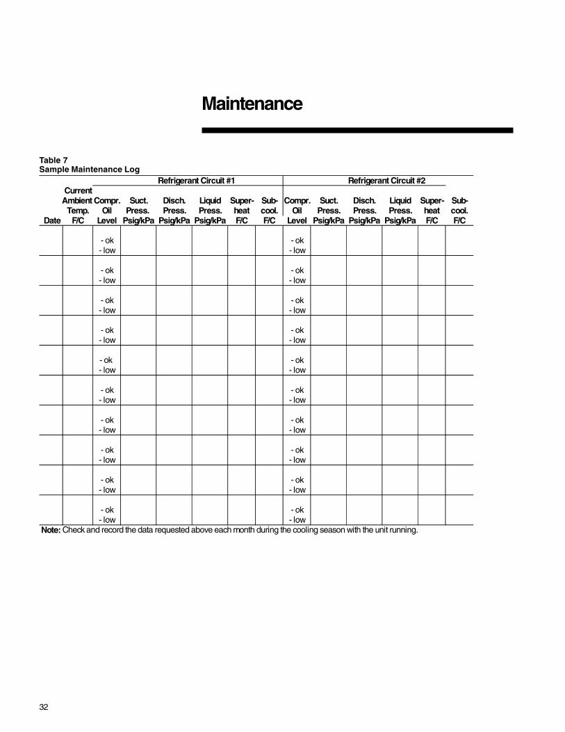
Table 7Sample Maintenance Log
Refrigerant Circuit #1 Refrigerant Circuit #2 Current
Ambient Compr. Suct. Disch. Liquid Super- Sub- Compr. Suct. Disch. Liquid Super- Sub-Temp. Oil Press. Press. Press. heat cool. Oil Press. Press. Press. heat cool.
Date F/C Level Psig/kPa Psig/kPa Psig/kPa F/C F/C Level Psig/kPa Psig/kPa Psig/kPa F/C F/C
- ok - ok- low - low
- ok - ok- low - low
- ok - ok- low - low
- ok - ok- low - low
- ok - ok- low - low
- ok - ok- low - low
- ok - ok- low - low
- ok - ok- low - low
- ok - ok- low - low
- ok - ok- low - low
Note: Check and record the data requested above each month during the cooling season with the unit running.

33
Trouble Shooting
ReliaTel ControlThe RTRM has the ability to provide theservice personnel with some unit diag-nostics and system status information.
Before turning the main power discon-nect switch “Off”, follow the steps belowto check the ReliaTel RefrigerationModule (RTRM). All diagnostics & sys-tem status information stored in theRTRM will be lost when the main poweris turned “Off”.
WARNINGHazardousService Procedures!
The maintenance and troubleshoot-ing procedures recommended in thissection of the manual could result inexposure to electrical, mechanical orother potential safety hazards. Al-ways refer to the safety warningsprovided throughout this manualconcerning these procedures. Whenpossible, disconnect all electricalpower including remote disconnectsbefore servicing. Follow proper lock-out/tagout procedures to ensure thepower can not be inadvertently ener-gized. When necessary to work withlive electrical components, have aqualified licensed electrician orother individual who has beentrained in handling live electricalcomponents perform these tasks.Failure to follow all of the recom-mended safety warnings provided,could result in death or serious in-jury.
To prevent injury or death from electro-cution, it is the responsibility of thetechnician to recognize this hazard anduse extreme care when performingservice procedures with the electricalpower energized.
1. Verify that the Liteport LED on theRTRM is burning continuously. If theLED is lit, go to Step 3.
2. If the LED is not lit, verify that 24 VACis presence between J1-1 and J1-2.If 24 VAC is present, proceed to Step3. If 24 VAC is not present, check theunit main power supply, check trans-former (TNS1). Proceed to Step 3 ifnecessary.
3. Utilizing “Method 1” or “Method 2” inthe “System Status Checkout Proce-dure” section, check the following:
System statusHeating statusCooling status
If a System failure is indicated, pro-ceed to Step 4. If no failures are indi-cated, proceed to Step 5.
4. If a System failure is indicated, re-check Steps 1 and 2. If the LED isnot lit in Step 1, and 24 VAC ispresent in Step 2, the RTRM hasfailed. Replace the RTRM.
5. If no failures are indicated, use oneof the TEST mode procedures de-scribed in the “Unit Start-Up” sectionto start the unit. This procedure willallow you to check all of the RTRMoutputs, and all of the external con-trols (relays, contactors, etc.) that theRTRM outputs energize, for each re-spective mode. Proceed to Step 6.
6. Step the system through all of theavailable modes, and verify opera-tion of all outputs, controls, andmodes. If a problem in operation isnoted in any mode, you may leavethe system in that mode for up toone hour while troubleshooting. Re-fer to the sequence of operations foreach mode, to assist in verifyingproper operation. Make the neces-sary repairs and proceed to Steps 7and 8.
7. If no abnormal operating conditionsappear in the test mode, exit the testmode by turning the power “Off” atthe main power disconnect switch.
8. Refer to the individual componenttest procedures if other microelec-tronic components are suspect.
System Status Checkout Procedure
“System Status” is checked by usingone of the following two methods:
Method 1
If the Zone Sensor Module (ZSM) isequipped with a remote panel with LEDstatus indication, you can check the unitwithin the space. If the ZSM does nothave LED’s, use Method 2.BAYSENS010B, BAYSENS011B,BAYSENS019B, BAYSENS020B,BAYSENS021A & BAYSENS023A allhave the remote panel indication fea-ture. The LED descriptions are listedbelow.
LED 1 (System)“On” during normal operation.“Off” if a system failure occurs or theLED fails.“Flashing” indicates test mode.
LED 2 (Heat)“On” when the heat cycle is operating.“Off” when the heat cycle terminates orthe LED fails.“Flashing” indicates a heating failure.
LED 3 (Cool)“On” when the cooling cycle is operat-ing.“Off” when the cooling cycle terminatesor the LED fails.“Flashing” indicates a cooling failure.
LED 4 (Service)“On” indicates a clogged filter.“Off” during normal operation.“Flashing” indicates an evaporator fanfailure
Below is the complete listing of failureindication causes.
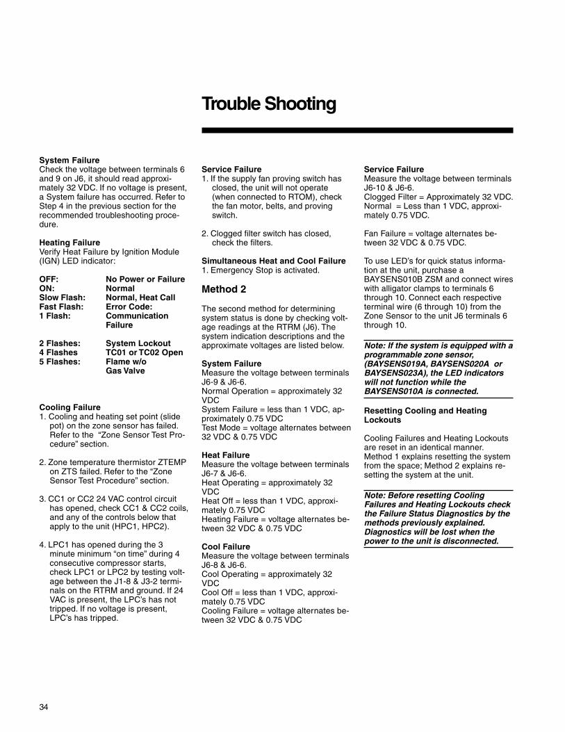
34
System FailureCheck the voltage between terminals 6and 9 on J6, it should read approxi-mately 32 VDC. If no voltage is present,a System failure has occurred. Refer toStep 4 in the previous section for therecommended troubleshooting proce-dure.
Heating FailureVerify Heat Failure by Ignition Module(IGN) LED indicator:
OFF: No Power or FailureON: NormalSlow Flash: Normal, Heat CallFast Flash: Error Code:1 Flash: Communication
Failure
2 Flashes: System Lockout4 Flashes TC01 or TC02 Open5 Flashes: Flame w/o
Gas Valve
Cooling Failure1. Cooling and heating set point (slide
pot) on the zone sensor has failed.Refer to the “Zone Sensor Test Pro-cedure” section.
2. Zone temperature thermistor ZTEMPon ZTS failed. Refer to the “ZoneSensor Test Procedure” section.
3. CC1 or CC2 24 VAC control circuithas opened, check CC1 & CC2 coils,and any of the controls below thatapply to the unit (HPC1, HPC2).
4. LPC1 has opened during the 3minute minimum “on time” during 4consecutive compressor starts,check LPC1 or LPC2 by testing volt-age between the J1-8 & J3-2 termi-nals on the RTRM and ground. If 24VAC is present, the LPC’s has nottripped. If no voltage is present,LPC’s has tripped.
Service Failure1. If the supply fan proving switch has
closed, the unit will not operate(when connected to RTOM), checkthe fan motor, belts, and provingswitch.
2. Clogged filter switch has closed,check the filters.
Simultaneous Heat and Cool Failure1. Emergency Stop is activated.
Method 2
The second method for determiningsystem status is done by checking volt-age readings at the RTRM (J6). Thesystem indication descriptions and theapproximate voltages are listed below.
System FailureMeasure the voltage between terminalsJ6-9 & J6-6.Normal Operation = approximately 32VDCSystem Failure = less than 1 VDC, ap-proximately 0.75 VDCTest Mode = voltage alternates between32 VDC & 0.75 VDC
Heat FailureMeasure the voltage between terminalsJ6-7 & J6-6.Heat Operating = approximately 32VDCHeat Off = less than 1 VDC, approxi-mately 0.75 VDCHeating Failure = voltage alternates be-tween 32 VDC & 0.75 VDC
Cool FailureMeasure the voltage between terminalsJ6-8 & J6-6.Cool Operating = approximately 32VDCCool Off = less than 1 VDC, approxi-mately 0.75 VDCCooling Failure = voltage alternates be-tween 32 VDC & 0.75 VDC
Service FailureMeasure the voltage between terminalsJ6-10 & J6-6.Clogged Filter = Approximately 32 VDC.Normal = Less than 1 VDC, approxi-mately 0.75 VDC.
Fan Failure = voltage alternates be-tween 32 VDC & 0.75 VDC.
To use LED’s for quick status informa-tion at the unit, purchase aBAYSENS010B ZSM and connect wireswith alligator clamps to terminals 6through 10. Connect each respectiveterminal wire (6 through 10) from theZone Sensor to the unit J6 terminals 6through 10.
Note: If the system is equipped with aprogrammable zone sensor,(BAYSENS019A, BAYSENS020A orBAYSENS023A), the LED indicatorswill not function while theBAYSENS010A is connected.
Resetting Cooling and HeatingLockouts
Cooling Failures and Heating Lockoutsare reset in an identical manner.Method 1 explains resetting the systemfrom the space; Method 2 explains re-setting the system at the unit.
Note: Before resetting CoolingFailures and Heating Lockouts checkthe Failure Status Diagnostics by themethods previously explained.Diagnostics will be lost when thepower to the unit is disconnected.
Trouble Shooting

35
Method 1
To reset the system from the space,turn the “Mode” selection switch at thezone sensor to the “Off” position. Afterapproximately 30 seconds, turn the“Mode” selection switch to the desiredmode, i.e. Heat, Cool or Auto.
Method 2
To reset the system at the unit, cyclethe unit power by turning the disconnectswitch “Off” and then “On”.
Lockouts can be cleared through thebuilding management system. Refer tothe building management system in-structions for more information.
Zone Temperature Sensor (ZTS)Service Indicator
The ZSM SERVICE LED is a genericindicator, that will signal the closing of aNormally Open switch at any time, pro-viding the Indoor Motor (IDM) is operat-ing. This indicator is usually used to in-dicate a clogged filter, or an air side fanfailure.
The RTRM will ignore the closing of thisNormally Open switch for 2 (±1) min-utes. This helps prevent nuisance SER-VICE LED indications. The exception isthe LED will flash 40 seconds after thefan is turned “On” if the Fan ProvingSwitch is not made.
Clogged Filter SwitchThis LED will remain lit the entire timethat the Normally Open switch isclosed. The LED will be turned off im-mediately after resetting the switch (to
the Normally Open position), or anytime that the IDM is turned “Off”.
If the switch remains closed, and theIDM is turned “On”, the SERVICE LEDwill be turned “On” again after the 2(±1) minute ignore delay.
This LED being turned “On”, will haveno other affect on unit operation. It is anindicator only.
Fan Failure SwitchWhen the “Fan Failure” switch is wiredto the RTOM, the LED will remain flash-ing the entire time the fan provingswitch is closed, indicating a fan failure,and it will shut the unit operationsdown.
Zone Temperature Sensor (ZTS) Test
Note: These procedures are not forprogrammable or digital models andare conducted with the Zone SensorModule electrically removed from thesystem.
Test 1Zone Temperature Thermistor(ZTEMP)
This component is tested by measuringthe resistance between terminals 1 and2 on the Zone Temperature Sensor. Be-low are some typical indoor tempera-tures, and corresponding resistive val-ues.
N o m in a l Z T E M P R e s is ta n c e
5 0 F ° 1 0 .0 C 1 9 .9 K -O h m s 5 5 F 1 2 .8 C 1 7 .4 7 K -O h m s6 0 F 1 5 .6 C 1 5 .3 K -O h m s 6 5 F 1 8 .3 C 1 3 .4 9 K -O h m s7 0 F 2 1 .1 C 1 1 .9 K -O h m s 7 5 F 2 3 .9 C 1 0 .5 0 K -O h m s8 0 F 2 6 .7 C 9 .3 K -O h m s 8 5 F 2 9 .4 C 8 .2 5 K -O h m s9 0 F 3 2 .2 C 7 .3 K -O h m s
Z o n e T e m p e r a tu r e
Test 2Cooling Set Point (CSP) and HeatingSet Point (HSP)
The resistance of these potentiometersare measured between the followingZSM terminals. Refer to the chartabove for approximate resistances atthe given setpoints.
Cool SP = Terminals 2 and 3Range = 100 to 900 Ohms approxi-mate
Heat SP = Terminals 2 and 5Range = 100 to 900 Ohms approximate
Trouble Shooting

36
Test 3System Mode and Fan Selection
The combined resistance of the Modeselection switch and the Fan selectionswitch can be measured between termi-nals 2 and 4 on the Zone Sensor. Thepossible switch combinations are listedbelow with their corresponding resis-tance values.
Resistance Zone Sensor Local Unit Local Fan Valves Unit/Fan(Ohms) Mode Mode Mode2.32K Off/ Auto Off Auto4.87K Cool/Auto Cool Auto7.68K Auto/Auto Auto Auto10.77K Off/On Off On13.32K Cool/On Cool On16.13K Auto/On Auto On19.48K Heat/Auto Heat Auto27.93K Heat/On Heat On35.0K Emergency Heat/Auto Emergency Heat Auto43.45K Emergency Heat/On Emergency Heat OnOut of Range (Short) INVALID/Short Invalid (CV), Auto (VAV) InvalidOut of Range (Open) INVALID/Open Invalid (CV), Off (VAV) Invalid
Test 4LED Indicator Test, (SYS ON, HEAT,COOL & SERVICE)
Method 1Testing the LED using a meter with di-ode test function. Test both forward andreverse bias. Forward bias should mea-sure a voltage drop of 1.5 to 2.5 volts,depending on your meter. Reverse biaswill show an Over Load, or open circuitindication if LED is functional.
Method 2Testing the LED with an analog Ohm-meter. Connect Ohmmeter across LEDin one direction, then reverse the leadsfor the opposite direction. The LEDshould have at least 100 times more re-sistance in reverse direction, as com-pared with the forward direction. If highresistance in both directions, LED isopen. If low in both directions, LED isshorted.
Trouble Shooting
Method 3To test LED’s with ZSM connected tounit, test voltages at LED terminals onZSM. A measurement of 32 VDC,across an unlit LED, means the LEDhas failed.
Note: Measurements should be madefrom LED common (ZSM terminal 6 torespective LED terminal). Refer to theZone Sensor Module (ZSM) TerminalIdentification table at the beginningof this section.

37
Trouble Shooting
Programmable & Digital Zone SensorTest
Testing serial communication voltage1. Verify 24 VAC is present between ter-
minals J6-14 & J6-11on the RTRM.
2. Disconnect wires from J6-11 and J6-12. Measure the voltage between J6-11 and J6-12, should be about 32VDC.
3. Reconnect wires to terminals J6-11and J6-12. Measure voltage againbetween J6-11 and J6-12, voltageshould flash high and low every 0.5seconds. The voltage on the low endwill measure about 19 VDC, whilethe voltage on the high end will mea-sure from approximately 24 to 38VDC.
4. Verify all modes of operation, by run-ning the unit through all of the stepsin the “Test Modes” section dis-cussed in “Unit Start-Up”.
5. After verifying proper unit operation,exit the test mode. Turn the fan oncontinuously at the ZSM, by pressingthe button with the fan symbol. If thefan comes on and runs continuously,the ZSM is good. If you are not ableto turn the fan on, the ZSM is defec-tive.
ReliaTel Refrigeration Module(RTRM) Default Chart
If the RTCI loses input from the buildingmanagement system, the RTRM willcontrol in the default mode after ap-proximately 15 minutes. If the RTRMloses the Heating and Cooling setpointinput, the RTRM will control in the de-fault mode instantaneously. The tem-perature sensing thermistor in the ZoneSensor Module is the only componentrequired for the “Default Mode” to oper-ate.
Unit Operation without a Zone Sensor
This procedure is for temporary opera-tion only. The economizer and con-denser fan cycling functions are dis-abled.
1. Open and Lock the unit disconnectswitch.
2. Remove the Outside Air Sensor(OAS) from the condenser section ofunit.
3. Use two (2) wire nuts, to individuallycap the wires.
4. Locate the RTRM (J6). Connect two(2) wires to terminals J6-1 and 2.
5. Connect the sensor (OAS) using twowire nuts to the two (2) field suppliedwires that were connected to termi-nals 1 and 2 on J6.
Unit Economizer Control (ECA) TroubleshootingReliaTel Control
Verify Economizer Status by Economizer Actuator (ECA) LED indicator:
OFF: No Power or FailureON: Normal, OK to EconomizeSlow Flash: Normal, Not OK to Economize
Fast Flash - 1/2 Second On / 2 Seconds Off: Error Code: Communications Failure
Pulse Flash: 2 Seconds On / 1/2 Second Off:Error Code:
1 Flash: Actuator Fault2 Flashes: CO2 Sensor3 Flashes: RA Humidity Sensor4 Flashes RA Temp Sensor5 Flashes: OA Quality Sensor6 Flashes: OA Humidity Sensor7 Flashes: OA Temp Sensor8 Flashes: MA Temp Sensor9 Flashes: RAM Fault10 Flashes: ROM Fault11 Flashes: EEPROM Fault

38
Combination GasElectric Air ConditionerYCC, YCD, YCH, YCP, YSC and YHC (Parts Only)
Models Less Than 20 Tons for Residential Use*
This limited warranty is extended by American Standard Inc., to the original purchaser and to any succeeding owner ofthe real property to which the Combination Gas Electric Air Conditioner is originally affixed, and applies to productspurchased and retained for use within the U.S.A. and Canada.
If any part of your Combination Gas Electric Air Conditioner fails because of a manufacturing defect within five years fromthe date of the original purchase, Warrantor will furnish without charge the required replacement part. Any localtransportation, related service labor, diagnosis calls, air filters, refrigerant and related items are not included.If the sealed motor-compressor fails because of a manufacturing defect within five years from the date of originalpurchase, Warrantor will furnish without charge the required replacement compressor. Any local transportation, relatedservice labor, diagnosis calls, refrigerant and related items are not included.
In addition, if the steel heat exchanger fails because of a manufacturing defect within the sixth through twentieth year fromthe date of original purchase, Warrantor will furnish without charge a replacement heat exchanger. Any local transportation,related service labor and diagnosis calls are not included.
This limited warranty does not cover failure of your combination gas electric air conditioner if it is damaged while in yourpossession, failure attributable or caused by unreasonable use of the combination gas electric air conditioner and/orfailure to properly maintain the combination gas electric air conditioner as set forth in the Use and Care manual.This limited warranty applies to product installed on or after 10/1/2001 where product is manufactured after 1/1/2000. Thislimited warranty is not retroactive to any installations prior to 10/1/2001 or on product produced prior to 2000.
THE LIMITED WARRANTY AND LIABILITY SET FORTH HEREIN ARE IN LIEU OF ALL OTHER WARRANTIES ANDLIABILITIES, WHETHER IN CONTRACT OR IN NEGLIGENCE, EXPRESS OR IMPLIED, IN LAW OR IN FACT, INCLUDINGIMPLIED WARRANTIES OF MERCHANTABILITY AND FITNESS FOR PARTICULAR USE, AND IN NO EVENT SHALLWARRANTOR BE LIABLE FOR ANY INCIDENTAL OR CONSEQUENTIAL DAMAGES.
Some states do not allow limitations on how long an implied limited warranty lasts or do not allow the exclusion orlimitation of incidental or consequential damages, so the above limitation or exclusion may not apply to you. This limitedwarranty gives you specific legal rights, and you may also have other rights which vary from state to state.Parts will be provided by our factory organization through an authorized service organization in your area listed in theyellow pages. If you wish further help or information concerning this limited warranty, contact:
American Standard Inc.2701 Wilma Rudolph Blvd.Clarksville, TN 37040-1008Attention: Manager, Product Service
GW-618-4001
* This limited warranty is for residential usage of this equipment and not applicable when this equipment is used for acommercial application. A commercial use is any application where the end purchaser uses the product for other thanpersonal, family or household purposes.
Warranty

39
�Standard Equipment WarrantyTerms and Conditions
Commercial Equipment Warranty and LiabilityModels Larger that 20 Tons for Commercial Use*
The Company warrants for a period of 12 months from initial start-up or 18months from date of shipment, whichever is less, that the Company prod-ucts covered by this order (1) are free from defects in material and work-manship and (2) have the capacities and ratings set forth in the Company’scatalogs and bulletins, provided that no warranty is made against corrosion,erosion or deterioration.The Company’s obligations and liabilities under thiswarranty are limited to furnishing f.o.b. factory or warehouse at Companydesignated shipping point, freight allowed to Buyer’s city (or port of exportfor shipment outside the conterminous United States) replacement equip-ment (or at the option of the Company parts therefore) for all Companyproducts not conforming to this warranty and which have been returned tothe manufacturer. The Company shall not be obligated to pay for the cost oflost refrigerant. No liability whatever shall attach to the Company until saidproducts have been paid for and then said liability shall be limited to thepurchase price of the equipment shown to be defective.
The Company makes certain further warranty protection available on anoptional extra-cost basis. Any further warranty must be in writing, signed byan officer of the Company.
The warranty and liability set forth herein are in lieu of all other warrantiesand liabilities, whether in contract or in negligence, express or implied, in lawor in fact, including implied warranties of merchantability and fitness forparticular use. In no event shall the Company be liable for any incidental orconsequential damages.
American Standard Inc.2701 Wilma Rudolph Blvd.Clarksville, TN 37040-1008Attention: Manager,Product Service
Warranty

An American Standard CompanySince the manufacturer has a policy of continuous product improvement, it reserves the right to change design andspecifications without notice.
Literature Order Number
File Number
Supersedes
Stocking Location
YC-IOM-13SV-UN-RT-YC-IOM-13 12/04
YC-IOM-13 4/03