installation, operation, and maintenance manualtable of contents section description page 1.0...
TRANSCRIPT

SS EE RR II EE SS OO FF MM EE TT EE RR II NN GG PP UU MM PP SS
DUAL SEAL PLUNGERVINSTALLATION, OPERATION, AND
MAINTENANCE MANUAL

P125V125P250V225P250V300
P500V225P500V300P500V400(1)
P750V400(1)
P1000V400(1)
P1000V600(1)
P1000V800(1)
NOTE: (1) The 400, 600 and 800 motor cylinders are only available with the CR (controller-relay) or SR (solenoid-relay) control methods.
CR P1000V800 A PEC: Controller
CR: Controller - RelayS: Solenoid Valve
SR: Solenoid Valve - Relay
ControlMethod
BasicModel(2)
A: 17-4 phB: 316 SS
CR: Ceramic
PlungerMaterial
PE: Polyethylene (UHMW)TC: Teflon® CompositeTG: Teflon® Graphite
V: Viton®
BR: Buna NK: Kalrez®
EPR: Ethylene Propylene
SealMaterial
PART NUMBER DESIGNATION
SS EE RR II EE SS OO FF MM EE TT EE RR II NN GG PP UU MM PP SS
DUAL SEAL PLUNGERV

TABLE OF CONTENTS
Section Description Page
1.0 FUNCTIONAL DESCRIPTION 1
1.1 Physical Description 1
1.2 Capabilities 3
1.3 General Operating Sequence 9
2.0 INSTALLATION OF PUMP AND CONTROLLER 10
2.1 General 10
2.2 Pump Assembly 10
2.3 Typical Installation 11
2.4 Supply Reservoir 11
2.5 Relief Valve 11
3.0 START UP, OPERATION & SHUTDOWN 11
3.1 General 11
3.2 Startup 11
3.3 Operation 12
3.4 Shutdown and Storage 12
4.0 MAINTENANCE 12
4.1 General 12
4.2 Disassembly and Assembly 13
4.3 Preventive Maintenance 23
4.4 Troubleshooting 23
5.0 PARTS LIST AND REPAIR KIT ORDERING REFERENCE 26
5.1 Controller Part Lists and Repair Kits 26
5.2 Relay Part Lists and Repair Kits 26

SECTION 1.0: FUNCTIONALDESCRIPTION
1.1 PHYSICAL DESCRIPTION
The letters CP at the beginning of a pumpassembly model number mean that themodel consists of a controller (C) andpump (P) For example: CP125V125,CP250V225, CP250V300, CP500V225, and
Control Methods For The Pump
1
1.1.1 ControllerThe controller, consisting of an upper andlower chamber separated by a slidingspool, uses a capillary tube with a needlevalve to transfer the supply air/gas fromthe lower to the upper chamber. When thesliding spool is in its highest position, apilot plug closes a vent and moves thesupply air/gas to the pump or relay. In thespools lowest position, the reverse is true;the pilot plug prevents supply air/gas from
CP500V300. The letters CRP mean that themodel also has a relay (R). For example:CRP500V400, CRP750V400, CRP1000V400,CRP1000V600, and CRP1000V800.
Some pumps use different relay sizes:• CRP500V400, CRP750V400,
CRP1000V400, and CRP1000V600pumps use the PO3-6S relay.
• CRP1000V800 pump uses the PO4-6Srelay.
The PNEUMATIC RELAY is a pilot operated valve designed to provide the higherair or gas flow rates necessary for PNEUMATIC DRIVE CYLINDER
diameters greater than 3 inches. The PNEUMATIC RELAY is actuated by the pulses produced bythe CONTROLLER. A single acting PNEUMATIC RELAY is used with pumps that have return springs as illustrated to the left.The air or gas pressure is required to return the PISTON-PLUNGER ASSEMBLY on the CRP1000V800. Therefore a doubleacting PNEUMATIC RELAY is required, illustrated to the right.
The MK XIIA Controller operates on the same operating principal as the MK X Controller.The MK XIIA has the same upper and lower chambers, but are separated with flexiblediaphragms rather than sliding seals. A capillary tube, controlled by a needle valve,transfers the air/gas supply to the pump from the lower to the upper chamber.
When the spool is in the highest position, a pilot plug closes a vent and opens thesupply air/gas to the pump. When the spool is in its lowest position, the pilot plugprevents the supply air/gas from entering the pump, and opens the air/gas vent to let itexhaust the pump. The spool then returns to its highest position to repeat the process.
1. Oscillamatic ® ControllerSTROKE RATE
CONTROL KNOBNEEDLE VALVE
CONTROL SPOOL
AIR/GAS SUPPLYTO CONTROLLER
SUPPLY TO PUMP1/4” NPT
EXHAUST VALVE
OPTIONAL 3-15CONTROL PORT(MK XIIB) 1/8” NPT
CONTROLAIR PASSAGE
UPPER DIAPHRAGM
MIDDLE DIAPHRAGM
LOWER DIAPHRAGM
SUPPLY VALVE
EXHAUSTFROM PUMP
1/4” NPT
3. Solenoid Valves
The pumps can be automated by replacing theCONTROLLER with a 3-way electro-pneumaticSOLENOID VALVE. The SOLENOID VALVE can becycled in order to achieve the desired pump output.Flow tracking can be accomplished by having aFLOWMETER or PH METER signal interpreted by ourWPC9001 or a PLC. The typical arrangement for aWPC-9001 installation is shown at right.
CONTROLLER
PO3-6S RELAY
CONTROLLER
P04-6S RELAY
PILOT PULSES FROMCONTROLLER
EXHAUST
SINGLE ACTINGPO3-6S DOUBLE ACTING
PO4-6S
PUMP
SUPPLYPRESSURE(REAR)
SUPPLY PRESSURE
EXHAUST NO. 1
PUMP POWERSTROKE NO. 1
PUMP RETURNSTROKE NO. 2
EXHAUST NO. 2
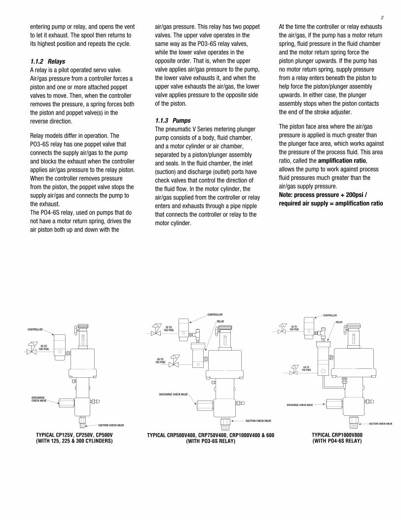
PUMP INSTALLATIONCRP500V400,CRP750V400
CRP1000V400CRP1000V600
PUMP INSTALLATIONCRP1000V800
PILOT PULSESFROM CONTROLLER
2. Controller-Pneumatic Relay Combination
At the time the controller or relay exhauststhe air/gas, if the pump has a motor returnspring, fluid pressure in the fluid chamberand the motor return spring force thepiston plunger upwards. If the pump hasno motor return spring, supply pressurefrom a relay enters beneath the piston tohelp force the piston/plunger assemblyupwards. In either case, the plungerassembly stops when the piston contactsthe end of the stroke adjuster.
The piston face area where the air/gaspressure is applied is much greater thanthe plunger face area, which works againstthe pressure of the process fluid. This arearatio, called the amplification ratio,allows the pump to work against processfluid pressures much greater than theair/gas supply pressure.Note: process pressure + 200psi /required air supply = amplification ratio
air/gas pressure. This relay has two poppetvalves. The upper valve operates in thesame way as the PO3-6S relay valves,while the lower valve operates in theopposite order. That is, when the uppervalve applies air/gas pressure to the pump,the lower valve exhausts it, and when theupper valve exhausts the air/gas, the lowervalve applies pressure to the opposite sideof the piston.
1.1.3 PumpsThe pneumatic V Series metering plungerpump consists of a body, fluid chamber,and a motor cylinder or air chamber,separated by a piston/plunger assemblyand seals. In the fluid chamber, the inlet(suction) and discharge (outlet) ports havecheck valves that control the direction ofthe fluid flow. In the motor cylinder, theair/gas supplied from the controller or relayenters and exhausts through a pipe nipplethat connects the controller or relay to themotor cylinder.
35 TO100 PSIG
50 TO150 PSIG
CONTROLLER
RELAY
DISCHARGE CHECK VALVE
SUCTION CHECK VALVE
35 TO100 PSIG
CONTROLLER
DISCHARGE CHECK VALVE
SUCTION CHECK VALVE
35 TO100 PSIG
50 TO150 PSIG
CONTROLLER
RELAY
SUCTION CHECK VALVE
DISCHARGE CHECK VALVE
TYPICAL CRP1000V800(WITH PO4-6S RELAY)
TYPICAL CRP500V400, CRP750V400, CRP1000V400 & 600(WITH PO3-6S RELAY)
TYPICAL CP125V, CP250V, CP500V(WITH 125, 225 & 300 CYLINDERS)
2
entering pump or relay, and opens the ventto let it exhaust. The spool then returns toits highest position and repeats the cycle.
1.1.2 RelaysA relay is a pilot operated servo valve.Air/gas pressure from a controller forces apiston and one or more attached poppetvalves to move. Then, when the controllerremoves the pressure, a spring forces boththe piston and poppet valve(s) in thereverse direction.
Relay models differ in operation. ThePO3-6S relay has one poppet valve thatconnects the supply air/gas to the pumpand blocks the exhaust when the controllerapplies air/gas pressure to the relay piston.When the controller removes pressurefrom the piston, the poppet valve stops thesupply air/gas and connects the pump tothe exhaust.The PO4-6S relay, used on pumps that donot have a motor return spring, drives theair piston both up and down with the
3
1.2.1.1 Controller Supply PressureControllers will operate with the followingsupply pressures:
Maximum Minimumpsi bar psi bar
MK XII 100 6.9 35 2.4
To establish the proper air/gas supplypressure for the controller or relay, add200 psig or 13.8 barg to the processpressure the pump is working against.Then use the performance graphs locatedin section 1.2.2.2.Remember for a controller-relaycombination the controller supply pressureneed only be set at the minimum pressureof 35 psig or 2.4 barg. The relay supplywould be established in the aboveprocedure or refer to section 1.2.1.2.CAUTION: To prevent damage to thecontroller, always use a regulatorbetween the supply and the controller
when the air/gas supply pressure ismore than the maximum rating of yourcontroller.
1.2.1.2 Relay Supply PressureRelays, which require a separate airsupply, operate with supply pressuresbetween 35 psig (2.41 bar) and 150 psig(10.3 bar). The supply pressure must be 35psig minimum or equal to or greater thanthe process pressure plus 200 psi, dividedby the pump amplification ratio. (EXAMPLE:CRP1000V400 @ 1000 PSI + 200 PSIdivided by 15.38 = 78 air supply required.Refer to section 1.1.3 for the amplificationratio formula) When using a controller/relaycombination, hold the air/gas supplypressure to the controller to the minimumvalue of 35 psig, and the relay at 35 psigminimum.CAUTION: To prevent damage to therelay, always use a regulator betweenthe supply and the relay when thesupply pressure is more than 150 psig(10.3 bar).
1.2 CAPABILITIES
1.2.1 Controllers and RelaysControllers and relays will require separatesupply sources, and fortunately willoperate with air or any gas, such as carbondioxide, nitrogen or natural gas.WARNING: TO PREVENT INJURY, MAKESURE THAT ANY FLAMMABLE GASSUCH AS NATURAL GAS IS PROPERLYVENTED FOR SAFETY.CAUTION: If the gas could possiblydamage the standard elastomericmaterial, please contact yourdistributor or Williams InstrumentIncorporated for advice.
To increase the process fluid flow rate, twoor more pumps can be multiplexed: theirinlets and outlets connected in parallel.
1.2.2 Pumps
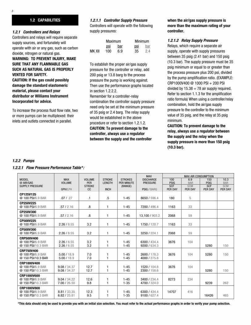
1.2.2.1 Flow Pressure Performance Table *:
MAX MAX AIR CONSUMPTIONMODEL MAX VOLUME STROKE STROKES DISCHARGE 100 6.9 150 10.3 @ AIR/GAS VOLUME PER LENGTH PER MINUTE PRESSURE PSIG BAR PSIG BARSUPPLY PRESSURE STROKE (RANGE) SCF SCM SCF SCM
GPH/LPH CC INCH PSIG / BARG PER DAY PER DAY PER DAY PER DAY
CP125V125@ 100 PSI/6.9 BAR .07 / .27 .1 .5 1-45 8650 / 596.4 180 5
CP250V225@ 100 PSI/6.9 BAR .57 / 2.16 .8 1 1-45 7200 / 496.4 1163 33
CP250V300@ 100 PSI/6.9 BAR .57 / 2.16 .8 1 1-45 13,100 / 903.2 2068 59
CP500V225@ 100 PSI/6.9 BAR 2.26 / 8.55 3.2 1 1-45 1750 / 120.7 1163 33
CP500V300@ 100 PSI/6.9 BAR 2.26 / 8.55 3.2 1 1-45 3250 / 224.1 2068 59
CRP500V400@ 100 PSI/6.9 BAR 2.26 / 8.55 3.2 1 1-45 6300 / 434.4 3676 104@ 150 PSI/10.3 BAR 2.26 / 8.55 3.2 1 1-45 9200 / 634.3 5280 150
CRP750V400@ 100 PSI/6.9 BAR 5.00 / 18.9 7.0 1 1-45 2600 / 178.3 3676 104 5280 150@ 150 PSI/10.3 BAR 5.00 / 18.9 7.0 1 1-45 4000 / 275.8
CRP1000V400@ 100 PSI/6.9 BAR 9.08 / 34.37 12.7 1 1-45 1520 / 104.8 3676 104@ 150 PSI/10.3 BAR 9.08 / 34.37 12.7 1 1-45 2300 / 158.6 5280 150
CRP1000V600@ 100 PSI/6.9 BAR 9.04 / 34.22 12.6 1 1-45 3400 / 234.4 8273 234@ 150 PSI/10.3 BAR 7.00 / 26.50 9.8 1 1-35 4700 / 324.0 9239 262
CRP1000V800@ 100 PSI/6.9 BAR 8.81 / 33.35 12.3 1 1-45 6300 / 434.4 14707 416@ 150 PSI/10.3 BAR 6.82 / 25.81 9.5 1 1-35 9100 / 627.4 16426 465
*This data should only be used to provide you with an initial size selection. You must refer to the actual performance graphs in order to verify your pump selection.
4
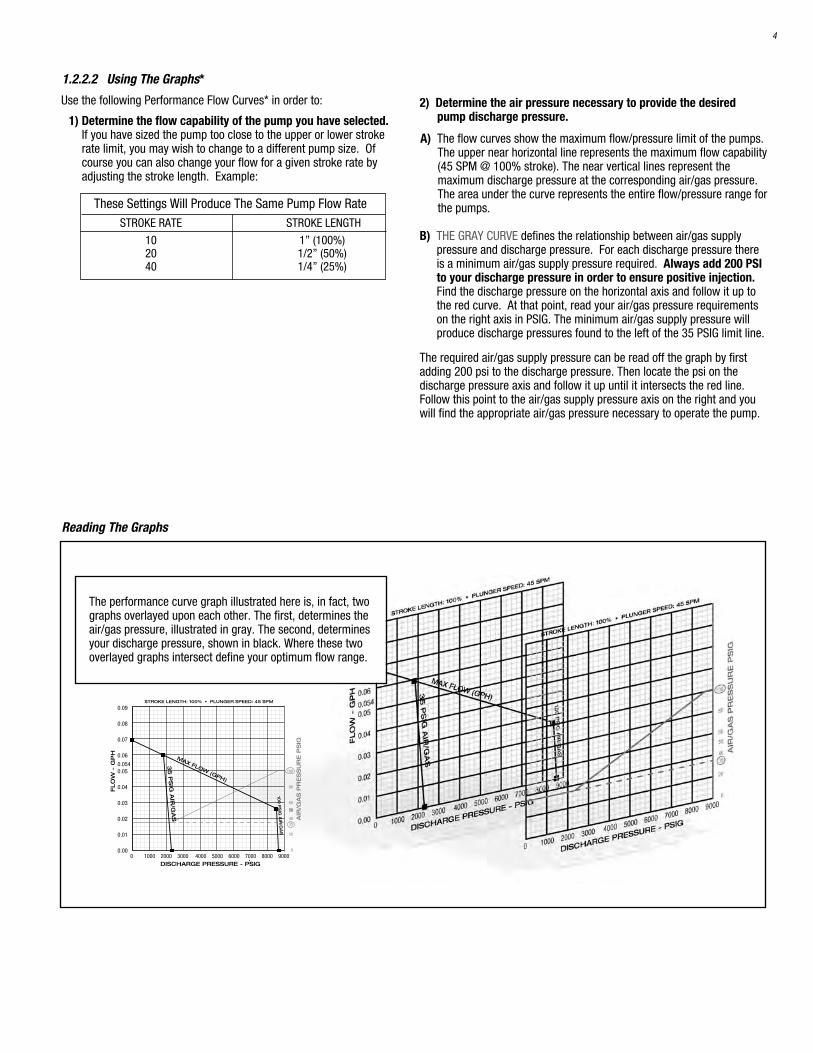
1.2.2.2 Using The Graphs*
Use the following Performance Flow Curves* in order to:
1) Determine the flow capability of the pump you have selected.If you have sized the pump too close to the upper or lower strokerate limit, you may wish to change to a different pump size. Ofcourse you can also change your flow for a given stroke rate byadjusting the stroke length. Example:
2) Determine the air pressure necessary to provide the desired pump discharge pressure.
A) The flow curves show the maximum flow/pressure limit of the pumps.The upper near horizontal line represents the maximum flow capability(45 SPM @ 100% stroke). The near vertical lines represent themaximum discharge pressure at the corresponding air/gas pressure.The area under the curve represents the entire flow/pressure range forthe pumps.
B) THE GRAY CURVE defines the relationship between air/gas supplypressure and discharge pressure. For each discharge pressure thereis a minimum air/gas supply pressure required. Always add 200 PSIto your discharge pressure in order to ensure positive injection.Find the discharge pressure on the horizontal axis and follow it up tothe red curve. At that point, read your air/gas pressure requirementson the right axis in PSIG. The minimum air/gas supply pressure willproduce discharge pressures found to the left of the 35 PSIG limit line.
The required air/gas supply pressure can be read off the graph by firstadding 200 psi to the discharge pressure. Then locate the psi on thedischarge pressure axis and follow it up until it intersects the red line.Follow this point to the air/gas supply pressure axis on the right and youwill find the appropriate air/gas pressure necessary to operate the pump.
These Settings Will Produce The Same Pump Flow RateSTROKE RATE STROKE LENGTH
10 1” (100%)20 1/2” (50%)40 1/4” (25%)
The performance curve graph illustrated here is, in fact, twographs overlayed upon each other. The first, determines theair/gas pressure, illustrated in gray. The second, determinesyour discharge pressure, shown in black. Where these twooverlayed graphs intersect define your optimum flow range.
0 1000 2000 3000 4000 5000 6000 7000 8000 9000
0.09
0.08
0.07
0.06
0.05
0.04
0.03
0.02
0.01
0.00
FLO
W -
GP
H
STROKE LENGTH: 100% • PLUNGER SPEED: 45 SPM
DISCHARGE PRESSURE - PSIG
100
80
60
40
20
0
AIR
/GA
S P
RE
SS
UR
E P
SIG
35
100
PS
IG A
IR/G
AS
35
PS
IG A
IR/G
AS
0.054
50
MAX FLOW (GPH)
Reading The Graphs
0 1000 2000 3000 4000 5000 6000 7000 8000 9000
0.09
0.08
0.07
0.06
0.05
0.04
0.03
0.02
0.01
0.00
FLO
W -
GP
H
STROKE LENGTH: 100% • PLUNGER SPEED: 45 SPM
DISCHARGE PRESSURE - PSIG
100
80
60
40
20
0
AIR
/GA
S P
RE
SS
UR
E P
SIG
35
100
PS
IG A
IR/G
AS
35
PS
IG A
IR/G
AS
0.054
50
MAX FLOW (GPH)
AIR/GAS PRESSURE
0.80
0.70
0.60
0.50
0.40
0.30
0.20
0.10
0.00
FLO
W -
GP
H
0 1000 2000 3000 4000 5000 6000 7000 8000
100
80
60
40
20
0
AIR
/GA
S P
RE
SS
UR
E P
SIG
35
DISCHARGE PRESSURE - PSIG
35
PS
IG A
IR
100
PS
IG A
IR
STROKE LENGTH: 100% • PLUNGER SPEED: 45 SPM
MAX FLOW (GPH)
AIR/GAS PRESSURE
5
0 1500 3000 4500 6000 7500 9000 10500 12000 13500 15000
90
100
80
70
60
50
40
30
35
20
10
0
0.90
1.00
0.80
0.70
0.60
0.50
0.40
.030
0.20
0.10
0
FLO
W -
GP
H
STROKE LENGTH: 100% • PLUNGER SPEED: 45 SPM
DISCHARGE PRESSURE - PSIG
AIR
/GA
S P
RE
SS
UR
E P
SIG
100 P
SIG
AIR
/GA
S
AIR/G
AS PRES
SURE
MAX FLOW (GPH)
35
PS
IG A
IR/G
AS
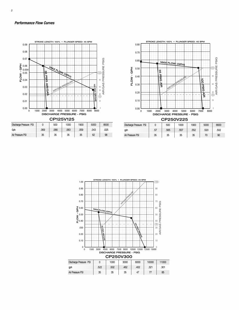
CP125V125DDiisscchhaarrggee PPrreessssuurree PPSSII 00 550000 11000000 11990000 55000000 88550000
GGpphh ..006699 ..006666 ..006633 ..005599 ..004433 ..002255
AAiirr PPrreessssuurree PPSSII 3355 3355 3355 3355 6622 9988
CP250V225DDiisscchhaarrggee PPrreessssuurree PPSSII 00 550000 11000000 11990000 55000000 66660000
ggpphh ..5577 ..556655 ..555577 ..555522 ..552200 ..550022
AAiirr PPrreessssuurree PPSSII 3355 3355 3355 3355 7700 9900
CP250V300DDiisscchhaarrggee PPrreessssuurree PPSSII 00 11000000 33000000 66000000 1100000000 1111000000
ggpphh ..552222 ..550022 ..446622 ..440022 ..332211 ..330011
AAiirr PPrreessssuurree PPSSII 3355 3355 3355 4477 7777 8855
Performance Flow Curves

6
160
140
120
100
80
60
40
20
150
0 1000 2000 3000 4000 5000 6000 7000 8000 9000 10000
2.50
2.25
2.00
1.75
1.50
1.25
1.00
0.75
0.50
0.25
0.00
DISCHARGE PRESSURE - PSIG
FLO
W -
GP
H
AIR
/GA
S P
RE
SS
UR
E -
PS
IG
35
35
PS
IG A
IR/G
AS
100
PS
IG A
IR/G
AS 15
0 P
SIG
AIR
/GA
S
STROKE LENGTH: 100% • PLUNGER SPEED: 45 SPM
MAX FLOW (GPH)
AIR/GAS P
RESSURE
100
90
80
70
60
50
40
30
20
10
0 200 400 600 800 1000 1200 1400 1600 1800 2000
2.50
2.25
2.00
1.75
1.50
1.25
1.00
0.75
0.50
0.25
0.00
DISCHARGE PRESSURE - PSIG
FLO
W -
GP
H
AIR
/GA
S P
RE
SS
UR
E -
PS
IG
35
STROKE LENGTH: 100% • PLUNGER SPEED: 45 SPM
100
PS
IG A
IR/G
AS
35
PS
IG A
IR/G
AS
MAX FLOW (GPH)
AIR/G
AS PR
ESSU
RE
0 500 1000 1500 2000 2500 3000 3500
3.00
2.75
2.50
2.25
2.00
1.75
1.50
1.25
1.00
0.75
0.50
0.25
0.00
DISCHARGE PRESSURE - PSIG
100
90
80
70
60
50
40
30
20
10
0
AIR
/GA
S P
RE
SS
UR
E P
SIG
35
FLO
W -
GP
H
PLUNGER SPEED: 45 SPM
100
PS
IG
35
PS
IG
MAX FLOW (GPH)
AIR/G
AS PRESSURE
CP500V225DDiisscchhaarrggee PPrreessssuurree PPSSII 00 220000 445500 11000000 11440000 11550000
ggpphh 22..2266 22..2266 22..2266 22..2233 22..2211 22..2211
AAiirr PPrreessssuurree PPSSII 3355 3355 3355 6600 8822 8888
CRP500V400DDiisscchhaarrggee PPrreessssuurree PPSSII 00 11550000 33000000 55000000 77000000 88110000
GGpphh 22..2266 22..2200 22..1155 22..0077 11..9999 11..9966
AAiirr PPrreessssuurree PPSSII 3355 3355 5522 8800 111100 113300
CP500V300DDiisscchhaarrggee PPrreessssuurree PPSSII 00 550000 880000 11550000 22000000 22550000
ggpphh 22..2266 22..2200 22..1166 22..0088 22..22 11..9966
AAiirr PPrreessssuurree PPSSII 3355 3355 3355 4488 6622 7777
Performance Flow Curves (cont.)

7
160
180
200
140
120
100
80
60
40
50
20
150
0 500 1000 1500 2000 2500 3000 3500 4000 4500 5000
10.00
9.00
8.00
7.00
6.00
5.00
4.00
3.00
2.00
1.00
0.00
DISCHARGE PRESSURE - PSIG
FLO
W -
GP
H
AIR
/GA
S P
RE
SS
UR
E -
PS
IG
50
PS
IG A
IR/G
AS
100
PS
IG A
IR/G
AS
150
PS
IG A
IR/G
AS
STROKE LENGTH: 100% • PLUNGER SPEED: 45 SPM
MAX FLOW (GPH)
AIR/G
AS PRESSURE
160
140
120
100
80
60
40
20
150
0 1000 2000 3000 4000 5000 6000 7000 8000 9000 10000
10.00
9.00
8.00
7.00
6.00
5.00
4.00
3.00
2.00
1.00
0.00
DISCHARGE PRESSURE - PSIG
FLO
W -
GP
H
AIR
/GA
S P
RE
SS
UR
E -
PS
IG
125
35
35
PS
IG A
IR/G
AS
150
PS
IG A
IR/G
AS
STROKE LENGTH: 100% • PLUNGER SPEED: 45 SPM & 35 SPM @ 150 PSIG
100
PS
IG A
IR/G
AS
125
PS
IG A
IR/G
AS
MAX FLOW (GPH)
AIR/G
AS PRESSURE
160
140
120
100
80
60
40
20
150
0 500 1000 1500 2000 2500 3000 3500 4000 4500 5000
10.00
9.00
8.00
7.00
6.00
5.00
4.00
3.00
2.00
1.00
0.00
DISCHARGE PRESSURE - PSIG
FLO
W -
GP
H
AIR
/GA
S P
RE
SS
UR
E -
PS
IG
125
35
35
PS
IG A
IR/G
AS
STROKE LENGTH: 100% • PLUNGER SPEED: 45 SPM & 35 SPM @ 150 PSIG
125
PS
IG A
IR/G
AS
100
PS
IG A
IR/G
AS
150 P
SIG
AIR
/GA
S
MAX FLOW (GPH)
AIR/GAS P
RESSURE
0 500 1000 1500 2000 2500
10.00
9.00
8.00
7.00
6.00
5.00
4.00
3.00
2.00
1.00
0.00
160
140
120
100
80
60
40
20
150
AIR
/GA
S P
RE
SS
UR
E -
PS
IG
35
35
PS
IG A
IR/G
AS
STROKE LENGTH: 100% • PLUNGER SPEED: 45 SPM
DISCHARGE PRESSURE - PSIG
150
PS
IG A
IR/G
AS
100
PS
IG A
IR/G
AS
MAX FLOW (GPH)
AIR/G
AS PRESSURE
CRP1000V400DDiisscchhaarrggee PPrreessssuurree PPSSII 00 331155 11000000 11220000 11775500 22000000
ggpphh 99..1122 99..1122 88..9999 88..8899 88..8888 88..8855
AAiirr PPrreessssuurree PPSSII 3355 3355 6666 7788 111122 113300
CRP750V400DDiisscchhaarrggee PPrreessssuurree PPSSII 00 550000 11550000 22000000 33000000 33550000
ggpphh 55..0000 44..9900 44..8800 44..7700 44..6600 44..5500
AAiirr PPrreessssuurree PPSSII 3355 3355 6600 8800 111155 113300
CRP1000V600DDiisscchhaarrggee PPrreessssuurree PPSSII 00 660000 22000000 22550000 44000000 44550000
GGpphh 99..0055 99..0000 88..8844 88..7799 11 11
AAiirr PPrreessssuurree PPSSII 3355 3355 6600 7755 112200 114400
CRP1000V800DDiisscchhaarrggee PPrreessssuurree PPSSII 00 11000000 11995500 55550000 77330000 88550000
ggpphh 88..8866 88..7799 88..7722 88..4466 66..2255 33
AAiirr PPrreessssuurree PPSSII 3355 3355 3355 8888 112200 114400
Performance Flow Curves (cont.)

8
1.2.2.3.2 Seal Material Selection
The seal material must be chosen to satisfy both the chemical compatibility and the pressures/temperatures at which you are operatingBelow is a general guideline for seal material selection.
1.2.2.3 Plunger & Seal Material
1.2.2.3.1 Plunger Material Selection
The materials available vary in hardness and chemical compatibility. We offer three materials based on our many years of industry experiencewith various chemicals. Hardness is a key property when selecting the proper plunger material. Our experience has shown that the harderplunger materials not only provide longer plunger life, they also provide greater seal life. A hard plunger is a must when pumping a chemicalthat is prone to crystallization or if the chemical is contaminated. Of course both of the preceding conditions will affect seal life. Below is atable that compares the chemical compatibility and hardness properties of each material.
Tough material with excellent wear resistance. Excellentchemical inertness. Good for all types of chemicals, acids,bases or solvents. Recommended for use with the harderceramic plunger and higher pressures.
Tough material with excellent wear resistance. Excellentchemical inertness. Good for all types of chemicals, acids,bases or solvents.
Tough material with excellent wear resistance. Good for waterand alcohol based chemicals. Not recommended for solvents.
Soft material with fair wear resistance. Broad chemicalcompatibility but its not to be used with ethyl or methylalcohols. Suggested only for hard to seal fluids in lowpressure applications when PE or TC will not seal.
Soft material with fair wear resistance. Limited chemical com-patibility. Used mainly in Methanol pumping at low pressure.
Soft material with fair wear resistance. Excellent chemicalcompatibility. Used when Viton® is not compatible and PE or TCwill not seal.
Material has very good abrasion resistance. Excellent chemi-cal resistance to phosphate esters, good to excellent to mildacids, alkalis, silicone oils and greases, ketones and alcohols.Not recommended for petroleum oils or di-esters.
SEAL TEMP SUGGESTED MATERIAL TYPE RANGE PRESSURE RANGE COMMENTS
TG Mechanical -30 to 180°F 1,000 to 10,000 psiTeflon® (Spring Loaded) -34 to 82°C 207 to 690 barGraphite (High Pressure)
TC Mechanical -30 to 180°F 750 to 9,000 psiTeflon® (Spring Loaded) -34 to 82°C 52 to 620 bar
Composite (Low Pressure)
PE Mechanical -30 to 180°F 100 to 3,000 psiUHMW (Spring Loaded) -34 to 82°C 6.9 to 207 bar
Polyethylene
V O-ring -10 to 200°F 100 to 750 psiViton® -23 to 93°C 6.9 to 52 bar
BR O-ring -40 to 200°F 100 to 750 psiBuna N -40 to 93°C 6.9 to 52 bar
K O-ring 32 to 200°F 100 to 750 psiKalrez® 0 to 93°C 6.9 to 52 bar
EPR O-ring -40 to 200°F 100 to 750 psiEthylene -40 to 93°C 6.9 to 52 bar
Propylene
Selecting the proper seal material for your application is important. We suggest using the harder plastic seals (PE, TC or TG) whenever possiblebecause they provide excellent wear life. The elastomers (V, BR, K or EPR) offer enhanced sealing at low pressure because they are soft and morecompliant than the plastics. However, the elastomers do not provide the same toughness or wear resistance.
DESIGNATION MATERIAL HARDNESS CHEMICAL COMPATIBILITY
CR Ceramic Between Sapphire and Diamond Excellent Chemical Inertness in on the Mohs’ Scale all Acids, Bases, Solvents
A 17-4 ph 40 RcGeneral Corrosion-resistant Stainless SteelLimited Acid Resistance
B 316 SS 28 RcExcellent Corrosion-resistantStainless SteelLimited Acid Resistance
We recommend the use of ceramic because of its extreme hardness and excellent chemical inertness.

9
Physical Specifications
B
H
I
CONTROLLERINLET 1/4" NPT (F)
BLEEDER1/4" BARBED FITTING
E
D
F
C
G
A ACONTROLLER
E
F
C
BP03-6S P500V400
RELAY INLET3/8" NPT (F)
RELAY
P1000V400P750V400
P1000V600P04-6S P1000V800
DI
H
J
G
BLEEDER1/4" BARBED FITTING
CONTROLLERINLET 1/4" NPT (F)
Model A B C D E F G H I J WTInch/mm Inch/mm Inch/mm Diameter (IN) Connector Connector Inch/mm Inch/mm Inch/mm Inch/mm LBS/KG
CP125V125 4.50/114.3 9.25/235 8.12/206.2 1 7/8”47mm 1/4” NPT (F) 1/4” NPT (M) 13/4”45mm 13/4”45mm 6 1/4”159mm n/a 7.0/3.2CP250V225 6.00/152.4 11.68/296.7 11.00/279.4 2 1/2”63.5mm 1/4” NPT (F) 1/4” NPT (M) 2 9/16”65mm 2 11/16”68mm 8 7/8”214mm n/a 9.0/4.1CP250V300 6.25/158.8 11.68/296.7 11.00/279.4 3 1/4”82.5mm 1/4” NPT (F) 1/4” NPT (M) 2 9/16”65mm 2 11/16”68mm 8 7/8”214mm n/a 9.0/4.1CP500V225 5.50/139.7 12.00/304.8 11.00/279.4 2 1/2”63.5mm 1/4” NPT (F) 1/2” NPT (M) 2 5/8”67mm 2 13/16”69mm 8 9/16”217mm n/a 10.0/4.5CP500V300 6.00/152.4 12.00/304.8 11.00/279.4 3 1/4”82.5mm 1/4” NPT (F) 1/2” NPT (M) 2 5/8”67mm 2 13/16”69mm 8 9/16”217mm n/a 10.0/4.5CRP500V400 9.12/232 16.00/406 11.00/279.4 4 1/4”108mm 1/4” NPT (F) 1/2” NPT (M) 2 5/8”67mm 2 13/16”69mm 12 3/4”324mm 9 7/16”240mm 15.0/6.8CRP750V400 9.75/247.6 16.25/412.7 11.31/287.2 4 9/16”116mm 1/2” NPT (F) 3/4” NPT (M) 35/8”92mm 3”76mm 13”332mm 7 9/16”240mm 16.7/7.5CRP1000V400 10.50/266.7 19.00/482.6 14.12/358.6 4 3/8”111mm 1/2” NPT (F) 3/4” NPT (M) 4”102mm 3 3/8”86mm 14 5/8”365mm 8 7/8”225mm 29.0/13.2CRP1000V600 12.50/317.5 19.00/482.6 14.12/358.6 6 3/8”162mm 1/2” NPT (F) 3/4” NPT (M) 4”102mm 3 3/8”86mm 17 3/4”451mm 12 1/4”214mm 35.5/16.1CRP1000V800 14.50/368.3 19.00/482.6 14.12/358.6 8 3/8”213mm 1/2” NPT (F) 3/4” NPT (M) 4”102mm 3 3/8”86mm 16”406mm 11”279mm 47.6/21.6
Model Plunger PistonDiameter (In.) Diameter (In.)
CP125V125 1/8 1 1/4CP250V225 1/4 2 1/4CP250V300 1/4 3CP500V225 1/2 2 1/4CP500V300 1/2 3CRP500V400 1/2 4CRP750V400 3/4 4CRP1000V400 1 4CRP1000V600 1 6CRP1000V800 1 8
1.3 GENERAL OPERATING SEQUENCE
1.3.1 Controller1.3.1.1 MK XII ControllerThe spool spring forces the spool upwardto its highest position and unseats the topof the pilot plug from the upper seat. Theexhaust spring forces the pilot plugupward and seats it on the lower seat. Thisblocks the air/gas exhaust port.
When high pressure air/gas enters thesupply port, it passes around and throughthe spool and past the open upper seat tothe motor cylinder port.
High pressure air/gas passes through thecontrol passage in the controller, past thevalve stem, and into the valve body upperchamber which causes pressure to buildup in the chamber. Because the surfacearea of the upper U-cup diaphragm ismuch larger than that of the middle U-cupdiaphragm, the downward force on thespool is greater than the upward force.This pressure pushes the spool down untilthe pilot plug seats itself on the uppervalve seat, shutting off the air/gas supply.
As the spool continues to move down, itpushes the pilot plug until the plug isunseated from the lower valve seat andallows the air/gas to exhaust through thelower valve from both the motor cylinderand the valve body volume chamber.
When the pressure in the chamber is lowenough, the spool spring starts pushingthe spool upward. The exhaust springpushes the pilot plug upward, and thecontroller returns to its initial position.
1.3.2 Relays1.3.2.1 PO3-6S RelayWhen there is no pilot pulse (high pressureair or gas) entering the top of the relayfrom the controller, the piston springpushes the piston and the poppetassembly upwards until the O-ring on topof the poppet presses against the upperbody section, sealing the pump port fromthe exhaust port. The space below thepoppet provides a path between the supplyand pump ports.When the controller sends a pilot pulse,the high pressure gas on top of the pistonovercomes the piston spring force, and
pushes the piston and the poppet assemblydownward until the O-ring on the bottom ofthe poppet presses against the lower bodysection, sealing the pump port from thesupply pressure. The space above thepoppet provides a path between the pumpand exhaust ports.
1.3.2.2 PO4-6S RelayWhen there is no pilot pulse (high pressureair or gas) entering the top of the relayfrom the controller, the piston springpushes the piston and two poppetsattached to the piston upwards until the O-ring on top of the upper poppet pressesagainst the upper body section and at thesame time the O-ring on the lower poppetpresses against the middle body section.The upper poppet O-ring seals the numberone pump port from the number oneexhaust port; the space below provides apath between the supply and the numberone pump ports. The lower poppet O-ringseals the number two pump port from thesupply port; the space below provides apath between the number two exhaust andpump ports.

10
When the controller sends a pilot pulse, thehigh pressure gas on top of the relay pistonovercomes the piston spring force andpushes the piston and two poppetsassemblies downward. The piston and twopoppets assemblies move down until the O-ring on the bottom of the upper poppetpresses against the middle body sectionand the O-ring on the bottom of the lowerpoppet presses against the lower bodysection. The upper poppet O-ring seals thenumber one pump port from the supplyport; the space above provides a pathbetween the number one pump andexhaust ports. The lower poppet O-ringseals the number two pump port from thenumber two exhaust port; the space belowprovides a path between the number twopump port and the supply port.
1.3.3 Pump Motor (Air Chamber)The motor forces the piston plunger to movealternately into and out of the pumpchamber. When the controller sends thesupply air/gas into the motor chamberthrough the nipple connector, the pressureon the piston and diaphragm overcomesthe combined force of the process fluidpressure on the piston plunger and plungerreturn spring, and pushes the plunger intothe fluid chamber. When the externalcontroller exhausts the air/gas, the pistonplunger return spring and process fluidpressure push the piston plunger out of thefluid chamber.
1.3.4 Pump (Fluid Chamber)The pump operating cycle consists of fluidbeing discharged and suctioned into thefluid chamber. During discharge, the pistonplunger moves into the pump fluidchamber, decreasing the volume of thechamber and raising the pressure in thechamber fluid. This higher pressure closesthe suction check valve and opens thedischarge check valve, sending the fluidinto the discharge line.
During the suction part of the cycle, thepiston plunger moves out of the fluidchamber, increasing the volume of thechamber and lowering the pressure of thechamber fluid. This lower pressure opensthe suction check valve and a spring closesthe discharge check valve, sending fluidfrom the suction line into the fluidchamber.
SECTION 2.0: INSTALLATION OFPUMP AND CONTROLLER
2.1 GENERAL
Always install separate pressure regulatorsin the air/gas supply lines for the controllerand the relay. Also, for the most efficientperformance of your pump assembly, werecommend the following:• A dryer and a dump valve in the air/gas
supply line to remove any moisture fromthe supply air/gas.
• Isolation valves (ball type) on inlet anddischarge lines of the pump and in theair/gas supply line to simplifymaintenance.
• A check valve where the pumpdischarge line joins the main processline to prevent process fluid back flow.
• An inlet filter, with filtrationapproximately 25 microns, on pumpsuction line.
• A flow meter or a rate setting gauge inthe suction line or process fluiddischarge line, if you need precise flowrate adjustment or recording.
2.2 PUMP ASSEMBLY
Position the pump assembly with enoughspace around it to allow easy access to allcomponents for maintenance. Install theassembly with the pump inlet/suctioncheck valve pointing straight down. Thepump will not work as efficiently in anyother position since the inlet/suction checkvalve has no spring.NOTE: The pump assembly can beinstalled directly in the process linepiping without any additional supportbrackets.
SUPPLY BODY STROKES ELASTOMER SPOOL MODELS PRESSURE MATERIAL (SPM) STYLE
MK XIIA 35-100 PSI (2.4-6.9 Bar) 316 ss 1 - 45 Neoprene Diaphragm
MK X 35-100 PSI (2.4-6.9 Bar) 316 ss 1 - 45 Buna/TFE, Viton®/TFE U-Cup
CONTROLLER SPECIFICATIONS

11
2.4 SUPPLY RESERVOIR
Position the supply reservoir so that theliquid level will not be less than six inchesabove the inlet check valve (floodedsuction). While you can locate the reservoirat any height above the inlet check valve(net positive suction head), the limit is 100psig net positive suction head, which is thecracking pressure of the discharge checkvalve. We do not recommend using thepumps in a suction lift position since theywere not designed for such operation.
2.5 RELIEF VALVE
A safety relief valve is not necessary if thedownstream piping can withstand themaximum pressure the pump can generateat the available air supply pressure. Themaximum discharge pressure the pumpcan generate can be taken from theperformance graphs in section 1.2.2.2.When this pressure is reached the pumpwill stop. Example: A CP250V225ATCoperating at 35 psig is capable ofgenerating 2520 psig. The pump will stoppumping when the 2520 psig is reached.
SECTION 3.0: STARTUP, OPERATION,SHUTDOWN, AND STORAGE
3.1 GENERAL
While these procedures for startup,operation, shutdown, and storage aresimple, following them carefully andcorrectly will improve the performance andincrease the life of your pump assembly.CAUTION: To avoid damaging thecontroller valve stem, do not make ahabit of turning the pump ON and OFFwith the stroke rate control. Use therecommended ball valve in the air/gassupply line.
3.2 STARTUP
These startup procedures will produce aflow rate close to what you want. For amore precise flow rate, monitor with a flowmeter while making the final adjustment.
3.2.1 Air/Gas SupplyBefore starting up your pump assembly,make sure that the primary air/gas supply,compressor, tank of gas, or other source, isturned OFF. Also, set the pressureregulator(s) to ZERO pressure.
3.2.1.1 Supply Pressure: The air/gassupply pressure must be large enough toproduce a pump discharge pressure 200psi higher than the process pressure.Therefore, if the process pressure is 2800psig, the air/gas supply should provide apump discharge pressure of 3000 psig. Toset the supply pressure properly, use theperformance graphs in 1.2.2.2.NOTE: With a controller/relaycombination, the controller supplypressure should be at the minimumvalue, 35 psig (Ref. 1.2.1.1) and therelay supply pressure set per the aboveprocedure. Remember, the controller isnow supplying the relay and the relay issupplying the pump. Refer to section1.2.1.2 for the relay supply pressures.
3.2.1.2 Supply Piping: Since supplyingthe proper air volume to the pump iscritical for its operation, avoid long runs ofsmall diameter tubing, as follows:• Locate the main air/gas supply header
as close to the pump as possible.• Use no more than five feet of 1/4”
tubing to supply air/gas to the controller.• Always locate the controller or relay on
the pump.• Use no more than ten feet of 1/2” tubing
to supply air/gas to the relay.• If a solenoid valve controls the pump,
locate it no more than two feet away anduse 1/2” tubing to supply air/gas to thepump.
2.3 TYPICAL INSTALLATION
Below you will find a schematic for a typical “V” plunger pump installation. The key ingredients for a successful installation are: 1: Clean, dryregulated air for the controller 2: A flooded inlet supply 3: An inlet filter 4: A rate setting gauge 5: A line check valve at the point of injection6: Isolation valves for maintenance on each component.
Flow Tracking Controller Configuration Standard Pneumatic Controller Configuration
3-WAY SOLENOID VALVE
FLOWOR PHMETER
PROCESS FLUID
WPC 9001,APU,
OR PLC
24VDCPULSE
4-20mASIGNAL
CHECK VALVE
FLOWMETER
TOTALIZER
PUMP
DUMPVALVE
AIR/GASDRYERPRESSURE
REGULATOR
AIR/GASSUPPLY
RATE SETTINGGAUGE
INLETFILTER
CHEMICALSUPPLY
6 0 0 STROKESPER MINUTE
RESETNO FLOWSELECT
PUMP 1
PUMP
RATE
AUTO
MANUAL
CONTROL LOSSOF I/P
MANUALADJUST
0 100 %
PUMP 2
T O T A L
W P C 9 0 0 1
12345678
PUMP&
CONTROLLER
DUMPVALVE
AIR/GASDRYER
PRESSUREREGULATOR
AIR/GASSUPPLY
INLETFILTER
CHEMICALSUPPLY
PROCESS FLUID
CHECK VALVE
RATE SETTINGGAUGE
FLOWMETER
TOTALIZER
SECTION 4.0: MAINTENANCE
4.1 GENERAL
This section contains procedures fordisassembly and assembly of thecontroller, pump, and check valves, plusprocedures for preventive and correctivemaintenance. To maintain the reliability,durability, and performance of your pumpassembly and related components, it isessential to follow these proceduresexactly and carefully.For consistent, reliable performance,replace any O-rings, U-cups, or other sealsthat you remove. Order replacement sealkits with detailed instructions from yourdistributor or Williams InstrumentIncorporated.
12
3.2.2 Controller Stroke RateThe controller is preset at the factory toprovide each pump the maximum numberof strokes per minute at 35 psig (Ref.1.2.2.1 Performance Table). This settingfalls at 100 on the controller scale. AtZERO on the scale, the pump will not cycleand there will be no output.
To calibrate the controller stroke rate,follow this procedure:1. Rotate the stroke rate knob on the
controller clockwise (CW) to ZERO onthe stroke rate reference scale.
2. Turn the main air/gas supply to theregulator(s) to ON, and adjust theregulator to the desired pressure. (see3.2.1.1 for determining pressure.)
3. Set the flow rate for your application byusing the controller's stroke rate knobin combination with the pump's strokeadjuster. (Ref. 1.2.2.1 PerformanceTable)
If necessary, adjust the controller strokerate knob as follows:1. Loosen the set screw and remove the
knob.2. Adjust the valve stem to the desired
rate by hand by turning the stemclockwise (CW) to decrease the strokerate or counterclockwise (CCW) toincrease the rate. Use a timer, such asa stop watch, to determine the actualstroke rate.
3. Attach and set the knob at the desiredposition on the scale (100 on scales for45 spm, for example).
3.2.3 Pump Stroke LengthThe adjuster scale for the pump's strokelength is factory set so that a ZERO readingequals ZERO stroke length. Calibrate thescale as follows:1. Turn the stroke adjuster tee set screw
counterclockwise until the strokeadjuster knob is unlocked.
2. Turn the stroke adjuster knobcounterclockwise as far as it can go.The piston/plunger will be fullybottomed in the pump.
3. Loosen the two screws holding the dataplate; move the data plate until themiddle of the pin is at ZERO on thescale. Tighten the two screws.
4. Turn the stroke adjuster knob until the
middle of the pin is at the desired strokelength on the scale.
5. Tighten the tee knob clockwise until thestroke adjuster knob is locked.
3.3 OPERATION
3.3.1 Bleeder PlugShortly after the pump assembly beginsoperating, the metered liquid should beginflowing through the pump. To bleed airtrapped in the pump chamber, turn thebleeder plug CCW about a quarter turn.When the liquid is flowing steadily witheach pump stroke from the end of thebleeder plug, turn it CW until the flowstops. It is best to close the bleeder plugwhen the pump is discharging and beforethe suction stroke.NOTE: To catch the escaping liquid, slipa length of 1/4” plastic or rubber tubingover the hose barb of the bleeder plug.
3.3.2 Stroke RateSet the operating stroke rate, as follows:1. Set the stroke rate knob to a mark on
the scale that will produce a stroke rateclose to the one you want. Keep inmind that the scale reading is only anapproximate percent indication of theactual rate; generally the pumpmaximum stroke rate will be set at 100on the scale. NOTE: At the ZEROsetting on the controller stroke ratescale, the pump will not stroke, butas you rotate the knob toward 100,the rate will increase to themaximum strokes per minute foreach pump. (Ref. 1.2.2.1 PerformanceTable) To set the stroke rate correctly,you must time the exhausts as theyleave the bottom of the controller.
2. Count the number of pump strokesduring a one minute interval, using atimer such as a stop watch todetermine the actual stroke rate.
3. Adjust the knob to correct the strokerate as needed. Confirm by timing thestroke rate.
4. Repeat the above steps until you getthe correct stroke rate. EXAMPLE: Toget a stroke rate of 22 strokes perminute, set the knob to 50 whichshould produce approximately 25strokes per minute. Then reduce the
rate by resetting the knob to 48. If thisproduces 21 strokes a minute, movethe knob to 49, which should be veryclose to the 22 strokes per minute youwant. Confirm the rate by timing it.
3.4 SHUTDOWN AND STORAGE
To shut down the pump assembly, set thepressure regulator(s) to ZERO, and turn theair/gas supply to OFF.To store the pump assembly or if it will notbe used for a long time, do the following:1. Remove pump from the system.2. Flush out the pump chamber and check
valves with water or solvent; drain andthen blow the pump dry withcompressed air.
CAUTION: To prevent damage to thepump when you clean it, be sure to usea solvent compatible with the meteredfluid that will not damage the pumpseals. For a recommended solvent,contact your distributor or WilliamsInstrument Incorporated.3. Cap off the suction and discharge
check valve ports.4. You may leave the pump, controller,
and relay assembled, but make sure tostore them in a dry, protected place.
13
remove. Separate upper valve bodyfrom the lower section. (Fig. 2 & 3)
3. Lift off the upper body and diaphragm.Lift out the inner diaphragm assembly.Set aside. (Fig. 4 & 5)
4. Lift out the spool spring. (Fig. 6)5. Turn lower controller body upside down.
Use a 3/16” hex wrench to unscrewbottom plug. Remove the bottom plug,lower spring and pilot plug. (Fig. 7 & 8)
6. Return controller body as before andunscrew lower seat with a 3/16” hexwrench. Remove lower seat. (Fig. 9 & 10)
Whenever you disconnect any air/gas orfluid piping, cover all open ports in thepump assembly to prevent dirt fromentering.
4.2 DISASSEMBLY AND ASSEMBLY
4.2.1 Required Tools and MaterialsNecessary tools will vary by pumpassembly model but the following aretypical:• Adjustable wrench: 12”• Belt-spanner or web wrench• Open-end wrenches: various sizes• Hex wrenches: 7/64”, 1/8”, 9/64”,
3/16”, and 5/32”, 1/4”, 3/8”• Socket wrenches: various sizes with 2”
extension• Flat-blade Screwdrivers: 1/8” (2
required) and 1/4”• MK X Screwdriver in 3/16” hex Socket
Drive (Drawing 1)• Brass or plastic O-ring pick (1)• Torque wrench (15 in-lb to 122 in-lb
range)• Bench vise• Silicone grease, (Williams G321M4), or
synthetic grease (Williams GS102149)• Teflon tape 1/4”• Thread sealing compound
NOTE: See 4.3 Preventive Maintenancefor inspection and replacement of partsidentified throughout these procedures.
4.2.2 Controllers4.2.2.1 Mark XII ControllerRefer to the Mark XII Controller Parts List.To disassemble, do the following:1. Remove red cap. (Fig. 1)
2. The Mark XII has (4) four socket headcap screws holding the controllertogether. Use a 5/32” hex wrench to
Figure 2
Figure 3
Figure 4
Figure 5
Figure 1
Fig. 6
Fig. 7
Fig. 8
Fig. 9
Fig. 10

14
7. To disassemble the inner diaphragmand spool assembly, first remove outersleeve and mid ring by sliding past thediaphragms towards the upper seat.(Fig. 11, 12 & 13) Use a small screw
driver or hex wrench placed through theinner spacer holes and with a 9/16”wrench unscrew the upper seat andlower diaphragm. (Fig. 14) Place the top
diaphragm stop (and inner sleeve withscrew driver/hex wrench) into a soft jawvice with a vee notch. Lightly clamp top
reinstall the lower seat and spoolspring. Make sure the capillary holes inthe upper diaphragm, the mid ring andthe mid diaphragm are in line with thecapillary hole of the lower body. Use asmall awl or hex wrench to threadtogether. Install (1) one of the (4) bodyscrews from the under side through theloose parts and through the topdiaphragm. Now remove the awl andplace on top of the assembly the uppercontroller body. Insure its capillary holeis inline with the others. Loosely threadtogether the (1) one body screw. Installremaining (3) three screws and torqueall to 28 - 32 inch pounds.
diaphragm stop. Unscrew inner sleeve.(Fig. 15) Remove the mid diaphragmfrom the top diaphragm stop. (Fig. 16)
Remove the lower diaphragm from theupper seat. (Fig. 18)
8. Clean all metal parts. Inspect and orreplace all three diaphragms. Toreassemble, push the mid diaphragmonto the top diaphragm stop. Push thelower diaphragm onto the upper seat.Thread the inner spacer onto these (2)two diaphragm assemblies. With ascrew driver and 9/10” wrench, tightensecurely, but not enough to pucker thediaphragms. Install the mid ring,counter bore first, onto the diaphragmassembly past the lower diaphragm andthen past the mid diaphragm. Somemaneuvering of the diaphragms will beneeded. Install the outer sleeve bysliding past the lower diaphragm. Insurethe narrow seat on the sleeve goesagainst the mid diaphragm and thewider seat is against the lowerdiaphragm. Some maneuvering of thelower diaphragm will also be needed.The inner assembly is now complete.(Fig. 17 & 19)
9. To install the inner assembly into thelower controller body, be sure to
Figure 11
Figure 12
Figure 14
Figure 13
Figure 15
Figure 16
Figure 17
Figure 18
Figure 19

15
4.2.3 Relays: PO3-6S and PO4-6SRefer to the appropriate Parts List.Disassembly instructions 1 through 9 applyto all relays, instructions 10 and 11 applyonly to the PO3-6S, and instructions 12through 17 apply to the PO4-6S.1. Use a 9/64” hex wrench to remove the
top cap screws (Fig. 20 & 21). Turnscrews CCW.
Figure 20
Figure 212. Separate the top cap with data plate
from the upper body section. (Fig. 22)
Figure 223. Put a 7/64” hex wrench through the
side of the relay into the upper bodyexhaust port and into the hole in theupper poppet stem. (Fig. 23)
Figure 234. Use a 9/64” hex wrench to remove the
piston lock screw (Fig. 23)5. Pull out the piston, O-ring, and spring.
(Fig. 24 & 25)
Figure 299. Use a flat-blade screwdriver to unscrew
the lower poppet stem. (Fig. 29)10. PO3-6S: Pull out the upper poppet and
poppet body; the poppet stemconnector bolt will remain in one ofthe stems.(Fig. 30)
Figure 3011. PO3-6S: Put a screwdriver in the holes
of the poppet O-ring retainers and prythem off. (Fig. 31 & 32)
Figure 31
Figure 32NOTE: You can now reassemble thePO3-6S relay by coating the poppetstems, seals, and mating surfaces withsilicone grease, and then reversing theabove procedure.
Figure 24
Figure 256. Use a 5/32” hex wrench to remove the
bottom cap screws. (Fig. 26 & 27)
Figure 26
Figure 277. Separate the lower body section from
the upper body section. (Fig. 26 & 27)
Figure 288. Again, put the 7/64” hex wrench
through the hole in the upper poppetstem. (Fig. 29)

16
To continue disassembling the PO4-6S, dothe following:12. PO4-6S: At this point, repeat step 8,
however, if the lower and middlepoppet stems should separate, modifythe rest of this procedure accordingly.(Fig. 33 & 34)
Figure 33
Figure 3413. PO4-6S: Separate the upper poppet
stem from the middle stem and thepoppet body. The poppet stemconnector bolt will remain on one ofthe stems. (Fig. 35)
Figure 3514. PO4-6S: Use the flat-blade
screwdriver to unscrew the lowerpoppet stem.
15. PO4-6S: Pull out the middle stem andpoppet body. The poppet stemconnector bolt will remain in one ofthe stems. (Fig. 35)
16. PO4-6S: Put a 7/64” hex wrench orscrewdriver in the holes of the poppetO-ring retainers and pry them off. (Fig. 31) Then use the screwdriver topry out the O-rings.
Figure 40b. Remove the motor cylinder by unfastening
the 4 to 10 screws (depending on thepump model) holding the motor cylinderto the faceplate. (Fig. 41)
Figure 41c. Remove the piston plunger guide ring
and return spring. (Fig. 42 & 43)
Figure 42
Figure 43d. Now remove the retaining ring and
spring seat. The secondary seal (andassociated backup ring if O-rings arebeing used), will be found beneath thespring seat. (Fig. 44 & 45)
Figure 36NOTE: Reassemble the PO4-6S relay bycoating the poppet stems, seals, andmating surfaces with silicone grease,and then reversing the aboveprocedure.
4.2.4 P125, P250, P500, P750 & P1000Pumps4.2.4.1 Changing Plunger Seals1. Disassembly:a. Unscrew the pump body from the fluid
cylinder. The primary seal is visible inthe pump body. The plunger willprotrude from the pump body, throughthe seal. (Fig. 37, 38, 39 & 40)
Figure 37
Figure 38
Figure 39

17
Such conditions could lead to leakage orexcessive seal wear if not corrected.Replace parts that exhibit wear.
g. Install the new seals in accordance withthe illustrations shown. Use illustration Iif your are installing the spring loaded Ucup type seals, and illustration II if youare installing O-ring type seals. In eachcase the seals and back up rings can beeasily be pushed in place using onlyyour fingers. Make certain the order andposition in which the components areinstalled matches the illustration shown.Also make certain the seal assembliesare installed completely, none of theseal assembly should protrude. NOTE:APPLY A LITTLE GREASE FROMGS102149 GREASE TUBE TO THESEALS. BACK UP RINGS AND ALLTHREADS BEFORE INSTALLING.(Figs. 52, 53, 54, 55, 56 & 57)
Figure 52
Figure 53
Figure 54
Figure 47
Figure 48
Figure 49
Figure 50e. Remove both 1/8” NPT plugs in the
pump body so that all the old greaseand any dirt or debris can becleaned/flushed from the pump body.(Fig. 51)
Figure 51f. Thoroughly clean all internal pump
surfaces. Then inspect all metal sealingsurfaces such the seal gland andplunger for scratches, nicks orirregularities.
Figure 44
Figure 45The primary and secondary seals canbe removed from the pump bodyassembly using either the piston-plunger or a brass (or plastic) pick. Becareful not to scratch the metalsealing surfaces during the extractionprocess. The piston-plunger can beinserted alternately into each end ofthe pump body assembly to push outthe opposing seal (and backup ring ifpresent). The brass or plastic pick canbe used to hook the seal (and backupring) to pull them out. Caution mustbe used to make certain that thesealing surfaces are not scratchedduring the removal of the seal andback up ring. (Fig.46, 47, 48, 49 & 50)
Figure 46
18
2. REASSEMBLYa. Replace spring seat and retaining ring.
NOTE: The spring seat may be usedas the secondary seal installationtool. Place the seal face down in thecavity and push it into place with springseat. (Fig. 58 & 59)
Figure 58
Figure 59b. Thread the fluid cylinder to the pump
body. The parts are designed to betightened using a strap type wrenchwith the following torque values:
Figure 55
Figure 56
Figure 57
PUMP MODEL TORQUE (Ft-lbs)P125V (all) 50P250V (all) 50P500V 225 50P500V 300 100P500V 400 100P750V 400 100P1000V (all) 100
c. Now apply Williams GS102149 syntheticgrease to the plunger, and the piston U-cup.
d. Install the spring in the spring seat.Then simultaneously insert and rotatethe plunger through the spring into thepump body seals. It may be necessaryto open the bleeder plug during thisprocedure to vent any fluid in fluidcylinder.
e. Now, apply synthetic grease (GS102149)to the internal surface of the motorcylinder. Wrap the piston guide ringaround the piston, and while holding itin place, slide the motor cylinder overthe piston, the U-cup and guide ring.Align the holes in the motor cylinderwith the face plate and tighten the 4 to10 screws removed during thedisassembly process. Assembly screwtorque is 25 in-lbs.
Retaining Ring
Spring Seat(Seal Retainer)
Secondary Seal (Upper)
Backup Ring (Spacer)
O-ring Seal
Retaining Ring Groove
Faceplate
Pump Body
Grease Access Ports
Body O-ring Seal
Backup Ring(Plunger Guide)
Primary Seal (Lower)
O-ring Seal
Fluid Cylinder
Illustration I Illustration II
19
f. Lubricate the seals as follows: 1. Both 1/8” NPT plugs should have
been removed during the disassemblyof the pump to facilitate cleaning. Ifthis was not done, please do it now.
2. Thread the tube of grease (GS102149)that came with the seal kit into one ofthe lubrication access ports. (Fig. 60)
Figure 603. Now, squeeze the grease into the
lubrication cavity. Hold your finger overthe opposite lubrication cavity accesshole, alternately removing it to allowair to escape and to feel the greasepressurize the lube cavity. (Fig. 61)
Figure 614. When all the air have been expelled
from the lubrication cavity and onlygrease is exiting the opposite accesshole, the cavity is full.
5. Apply Swagelok SWAK thread sealantto both 1/8” NPT plugs and replace inpump housing. (Fig. 62)
Figure 62
4.2.4.2 Complete Pump Rebuild:Although there are some differencesbetween the pumps, they aredisassembled and reassemble inapproximately the same way. Theprocedures describe the differences.
Refer to the appropriate parts list, forthe pump you are rebuilding.(Fig.62)
Figure 63Disassemble the pumps as follows:1. Clamp the pump at the fluid cylinder in
a vice. Use jaw protectors to avoidscratching the pump. (Fig. 64)
Figure 642. Use the belt-spanner wrench to loosen
the body from fluid cylinder. Clamp onthe body or the motor cylinder. Continueturning the assembly by hand until thetwo parts separate. (Fig. 65)
Figure 65NOTE: The fluid cylinder of the pumpcan remain installed on the plumbing ifonly the pump and not the check valvesare to be serviced. Also, since the bodyand the fluid cylinder are made as amatched set, keep them together. donot substitute parts from other pumpsof the same model.3. Use the appropriate hex wrench to
remove the socket-head cap screwsand washers fastening the motorcylinder to the body. If the pump has apiston return spring it will push the twopieces apart (exception: CRP1000V800);if not, separate the motor cylinder fromthe body and faceplate.
4. Remove the piston/plunger assembly,piston U-cup (piston O-ring on theP1000V800), piston guide ring and thepiston return spring (on all pumpsexcept the P1000V800). The pistonguide ring will fall away from thepiston. Remove the piston U-cup (piston O-ring on the P1000V800). (Fig.66 &67)
Figure 66
Figure 67NOTE: Before doing the next step, put apiece of tape or other mark on theoutside surface of the cylinderfaceplate to align it with a body part forreassembly.5. Use the 5/16” open end wrench to
unscrew and remove the vent plug, andthe 3/16” hex wrench to unscrew andremove the two grease chamber plugs.Use the appropriate hex wrench tounscrew and remove the cap screwsand split washers fastening the cylinderfaceplate to the body. Slide thefaceplate off the body. On theP1000V800, remove the two faceplateO-rings. (Fig. 68, 69, 70 & 71)
Figure 68

20
Figure 69
Figure 70
Figure 716. On the P250 and P500, use a small
screwdriver or punch to push the filterplugs from the cylinder faceplate. (Fig.72, 73 & 74)
Figure 72
Figure 73
Figure 74CAUTION: Do not remove the face plateplug from the P1000V800. The filter plugretainers are permanently pressed intoplace at the factory. DO NOT REMOVETHEM.7. Use a pick if necessary to remove the
body seal O-ring, the primary plungerseal, and the plunger seal backup ringfrom the body. The piston-plunger canalso be used to push out the primaryseal and backup ring by reinstalling it inthe body faceplate assembly.(Fig. 75,76 & 77)
Figure 75
Figure 76
Figure 778. Clamp the body in the bench vise,
faceplate side up.9. Use a pick or small screwdriver to lift
the end of the spring seat retainerfrom the groove in the body. Whileholding the end free, slide the otherpick between the retainer and the bodyuntil the retainer is loose. (Fig.78 & 79)
Figure 78
Figure 7910. Remove the spring seat. On the
P1000V800 remove the two springseat O-rings. (Fig. 80 & 81)
Figure 80
Figure 8111. Use a pick if necessary to remove the
secondary plunger seal locatedbeneath the spring seat or remove theseal by installing the plunger in theopposite end of the body-faceplateassembly and pushing the seal out.(Fig. 82 & 83)

21
Figure 82
Figure 8312. Use the appropriate socket wrench
(3/4” or 7/8”) to unscrew the nut thatsecures the piston stop and removethe stroke adjuster assembly from themotor cylinder. (Fig. 84, 85 & 86)
Figure 84
Figure 85
Figure 8613. Clamp the fluid cylinder in the vise.
Use the adjustable wrench to unscrewand remove the inlet check valve,
discharge check valve, and bleederplug. Before reassembling the pump,clean all chambers, motor cylinder,and cylinder faceplate with anapproved solvent. Contact yourdistributor or Williams InstrumentIncorporated for a recommendedsolvent. Also, lubricate all O-rings andU-cups with silicone grease orsynthetic grease. (Fig. 87, 88, 89, 90& 91)
Figure 87
Figure 88
Figure 89
Figure 90
Figure 91Reassemble the pump as follows:1. On all pumps except the P125 and
P1000V800, install the filter plugs inthe body.
2. On all pumps except the P125, slidethe cylinder faceplate over the bodyand line up the mounting holes. Makesure that the marked side of thefaceplate aligns with the outside of thepump. On all pumps except the P125and P1000V800 also line up the ventholes in the faceplate with the filterplugs.
3. Install the screws with splitlockwashers and torque them to thevalues in the table.
PUMP TORQUE (in-lb)P125 15 - 20P250 15 - 20P500 15 - 20P750 15 - 20P1000 28 - 32
4. Clamp the body in the bench vise withthe faceplate end up.
5. For the P250, P500, P750, andP1000V600, install a new plunger sealin the upper area of the body by facingthe open side of the seal down towardthe grease chamber and using thespring seat to push the seal in. For theP125, push the seal in by hand or use aspecial tool made for this purpose(part no. WT201192).
6. On the P1000V800, put the two springseat O-rings on the spring seat and putthe spring seat in the body. On allpumps except the P1000V800, alignthe hole in the side of the spring seatwith the vent plug and use the 5/16”open end wrench to install the plug.
7. Separate one end of the retaining ringand put it in the groove inside the body.Use a finger to work the rest of the ringinto the groove until the other end is inplace.

22
8. Remove the body from the bench vise.At the threaded end of the body installthe body seal O-ring and the plungerseal backup ring followed by theplunger seal. Face the open side of theseal away from the grease chamber.
9. Place the fluid cylinder in the vise withthe body mating end facing up. Use theadjustable wrench to screw in thesuction check valve (ball end or hexplug end into the pump), dischargecheck valve, and bleeder plug. Arrowson the check valves indicate flowdirection. Use thread sealant and teflontape on the suction and dischargecheck valves.
10. Apply synthetic grease to the bodythreads and body seal O-ring. Screwthe body into the fluid cylinder until it ishand tight, then tighten with the web orbelt-spanner wrench per the followingtorque values.
PUMP MODEL TORQUE (Ft-lbs)P125V (all) 50P250V (all) 50P500V 225 50P500V 300 100P500V 400 100P750V 400 100P1000V (all) 100
11. On all pumps except the P1000V800,put one end of the piston return springin the spring seat. Install the piston U-cup (piston O-ring on the P1000V800)on the piston. Face the open side ofthe U-cup away from the plunger.
12. Apply synthetic grease liberally to thepiston/plunger assembly and insidethe motor cylinder; install thepiston/plunger assembly, without thepiston guide ring, into the body.
13. Put the piston guide ring on the piston;while holding the ends of the guidering together with a finger or thumb,slide the motor cylinder over thepiston.
14. Push the motor cylinder down to thecylinder faceplate; align the motorcylinder mounting holes.
15. Install all the screws with splitlockwashers.
16. Use the 9/64” hex wrench on theP125, P250, P500, and P750 and the1/4” hex wrench on the P1000, to
torque the socket-head cap screwsand split lock washers to the values inthe table.
PUMP TORQUE (in-lb)P125 15 - 20P250 15 - 20P500 15 - 20P750 15 - 20
P1000 118 - 122
17. To lubricate the seals for running, holda finger over one vent hole and insertthe end of the synthetic grease tubeinto the other vent hole. Squeezesynthetic grease into the greasechamber until you feel it pressingagainst your finger. Vent all the air.Wipe off excess synthetic grease,apply thread sealing compound to thevent plugs, and replace them.
4.2.5 Discharge Check Valves: All Pumps
Although there are several sizes ofdischarge check valves, they are alldisassembled and reassembled the sameway. Refer to the appropriate parts list.Disassemble the check valve as follows:1. Clamp the check valve body in the vise.2. Use the appropriate hex wrench to
unscrew and remove the retainer.3. Remove the body from the vise and
dump out the spring, ball seat, ball,sleeve, and Teflon® O-ring (Fig. 92)
Figure 924. Remove the Teflon® O-ring from the
sleeve.5. Inspect all the parts and replace them if
they are worn.
Reassemble the check valve as follows:1. Put the Teflon® O-ring in the sleeve and
drop the sleeve, O-ring first, into thebody.
2. Drop the ball into the body.3. Put the small end of the spring in the
spring cavity on the wide end (not theslotted end) of the ball seat. Drop thetwo parts, ball seat first, into the body.
4. Drop the retainer, spring cavity first, if ithas one, into the body and use theappropriate hex wrench to torque to thevalues in the table.
PUMP TORQUE (in-lb)P125 230 - 240
P250/500 230 - 240P750/P1000 118 - 122
4.2.6 Suction Check Valves: All Pumps Although there are several sizes of checkvalves with minor construction differences,they are all disassembled and reassembledthe same way. The procedures describethe differences. Refer to the appropriateparts list. Disassemble the check valve asfollows:1. Clamp the check valve body in the vise.2. Use the appropriate hex wrench to
unscrew and remove the retainer.(Fig. 93)
Figure 933. Remove the body from the vise and
dump out the ball, sleeve, and O-ring.NOTE: On the P125 and P250 youmay need a pick or small tool toremove the Teflon® O-ring inside thebody. (Fig. 94)
Figure 94
23
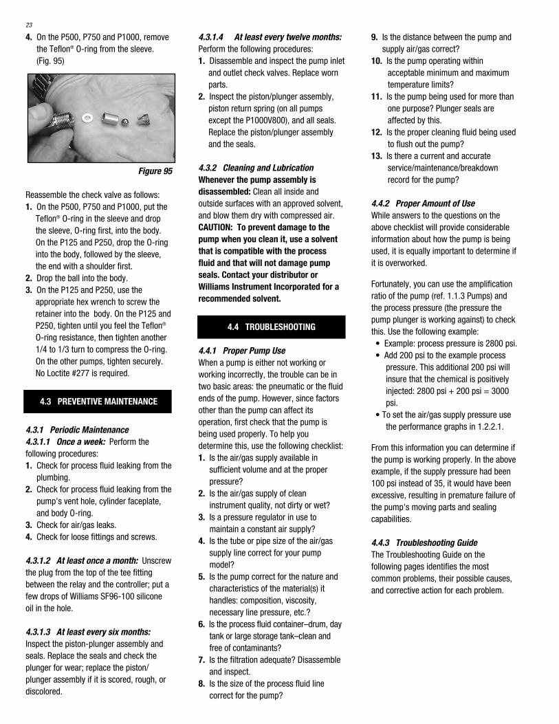
4. On the P500, P750 and P1000, removethe Teflon® O-ring from the sleeve. (Fig. 95)
Figure 95
Reassemble the check valve as follows:1. On the P500, P750 and P1000, put the
Teflon® O-ring in the sleeve and dropthe sleeve, O-ring first, into the body.On the P125 and P250, drop the O-ringinto the body, followed by the sleeve,the end with a shoulder first.
2. Drop the ball into the body.3. On the P125 and P250, use the
appropriate hex wrench to screw theretainer into the body. On the P125 andP250, tighten until you feel the Teflon®
O-ring resistance, then tighten another1/4 to 1/3 turn to compress the O-ring.On the other pumps, tighten securely.No Loctite #277 is required.
4.3 PREVENTIVE MAINTENANCE
4.3.1 Periodic Maintenance4.3.1.1 Once a week: Perform thefollowing procedures:1. Check for process fluid leaking from the
plumbing.2. Check for process fluid leaking from the
pump's vent hole, cylinder faceplate,and body O-ring.
3. Check for air/gas leaks.4. Check for loose fittings and screws.
4.3.1.2 At least once a month: Unscrewthe plug from the top of the tee fittingbetween the relay and the controller; put afew drops of Williams SF96-100 siliconeoil in the hole.
4.3.1.3 At least every six months:Inspect the piston-plunger assembly andseals. Replace the seals and check theplunger for wear; replace the piston/plunger assembly if it is scored, rough, ordiscolored.
4.3.1.4 At least every twelve months:Perform the following procedures:1. Disassemble and inspect the pump inlet
and outlet check valves. Replace wornparts.
2. Inspect the piston/plunger assembly,piston return spring (on all pumpsexcept the P1000V800), and all seals.Replace the piston/plunger assemblyand the seals.
4.3.2 Cleaning and LubricationWhenever the pump assembly isdisassembled: Clean all inside andoutside surfaces with an approved solvent,and blow them dry with compressed air.CAUTION: To prevent damage to thepump when you clean it, use a solventthat is compatible with the processfluid and that will not damage pumpseals. Contact your distributor orWilliams Instrument Incorporated for arecommended solvent.
4.4 TROUBLESHOOTING
4.4.1 Proper Pump UseWhen a pump is either not working orworking incorrectly, the trouble can be intwo basic areas: the pneumatic or the fluidends of the pump. However, since factorsother than the pump can affect itsoperation, first check that the pump isbeing used properly. To help youdetermine this, use the following checklist:1. Is the air/gas supply available in
sufficient volume and at the properpressure?
2. Is the air/gas supply of cleaninstrument quality, not dirty or wet?
3. Is a pressure regulator in use tomaintain a constant air supply?
4. Is the tube or pipe size of the air/gassupply line correct for your pumpmodel?
5. Is the pump correct for the nature andcharacteristics of the material(s) ithandles: composition, viscosity,necessary line pressure, etc.?
6. Is the process fluid container–drum, daytank or large storage tank–clean andfree of contaminants?
7. Is the filtration adequate? Disassembleand inspect.
8. Is the size of the process fluid linecorrect for the pump?
9. Is the distance between the pump andsupply air/gas correct?
10. Is the pump operating withinacceptable minimum and maximumtemperature limits?
11. Is the pump being used for more thanone purpose? Plunger seals areaffected by this.
12. Is the proper cleaning fluid being usedto flush out the pump?
13. Is there a current and accurateservice/maintenance/breakdownrecord for the pump?
4.4.2 Proper Amount of UseWhile answers to the questions on theabove checklist will provide considerableinformation about how the pump is beingused, it is equally important to determine ifit is overworked.
Fortunately, you can use the amplificationratio of the pump (ref. 1.1.3 Pumps) andthe process pressure (the pressure thepump plunger is working against) to checkthis. Use the following example:• Example: process pressure is 2800 psi.• Add 200 psi to the example process
pressure. This additional 200 psi willinsure that the chemical is positivelyinjected: 2800 psi + 200 psi = 3000psi.
• To set the air/gas supply pressure usethe performance graphs in 1.2.2.1.
From this information you can determine ifthe pump is working properly. In the aboveexample, if the supply pressure had been100 psi instead of 35, it would have beenexcessive, resulting in premature failure ofthe pump's moving parts and sealingcapabilities.
4.4.3 Troubleshooting GuideThe Troubleshooting Guide on thefollowing pages identifies the mostcommon problems, their possible causes,and corrective action for each problem.

24
TROUBLESHOOTING GUIDE
PROBLEM POSSIBLE CAUSE(S) CORRECTIVE ACTION
CONTROLLER NOT • Foreign material in controller • Put finger over exhaust port; alternately seal & vent port to OSCILLATING clear exhaust valve.
• No air/gas supply • Connect pressure gauge to port opposite supply line; verify required supply pressure.
• Supply pressure too high or too low • Reset regulator to proper pressure.
• Too much pressure drop in air/gas line • Increase connecting tube size or clean air lines.
• Stroke rate valve open too much • Disconnect air/gas supply. Rotate stroke rate knob CCW topeg, wait 5 seconds, & rotate knob CW until it stops.DO NOT FORCE KNOB.
Reconnect supply & rotate knob CCW until oscillations start.
Adjust stroke rate to proper strokes per minute according toSpecification Sheet; loosen knob set screw, rotate knob CCW to peg, & tighten screw.
• Leak between valve body & • Loosen; then retighten the connection between valve &controller body controller body. If dirty, disassemble, wipe clean and
reassemble.
• Continuous air flow from controller • Inspect & replace damaged lower seat and pilot plug.exhaust port (Pilot plug not seatingproperly)
• Air flowing from equalizer hole on • Inspect & replace ruptured or improperly seated seals.side of lower control body
Put finger over exhaust port; alternately seal & vent port to clear exhaust valve.
• Broken pilot plug, exhaust spring, • Replace damaged parts.or spool return spring
• Excessive water in controller • Install an air/gas dryer or separator in supply line.
RELAY NOT OPERATING • Broken piston return spring • Replace return spring. See page 15
• Poppet stem loosened from connector bolt • Tighten poppet stem to connector bolt. See page 15
• Air blow-by caused by poorly sealed O-rings • Improve quality of air supply and clean dirt from unit. Replace O-rings if damaged.
• Inadequate air supply • Check air regulator for proper pressure.
PLUNGER NOT STROKING • Controller control knob set at ZERO • Turn knob to proper setting on dial.
• Air/gas supply turned OFF • Open valve to allow air supply to flow to controller.
• Broken motor return spring • Replace return spring.
• Plunger stuck due to tight or dry seal • If seal is swollen, check its chemical compatibility with process fluid; replace with compatible seal material.
• If seal is dry, lubricate & fill reservoir with grease.
• Plunger bottomed • Readjust plunger stroke length. Replace return spring if broken.
• Excessive grease between cylinder and • Remove excess grease. Piston seal may be leaking; check faceplate and replace if necessary.
• Air/gas supply pressure too low to • Increase supply pressure to controller or relay.overcome process line pressure
• Discharge or suction line plugged • Clean the lines.

PLUNGER NOT STROKING • Air/gas flow to controller too low (controller • Install a larger capacity regulator or supply line. Vent supply (Cont.) locked up and will not cycle) side of controller and try to start pump at slowest speed;
increase speed slowly if controller starts to cycle.
• Motor cylinder-air piston blow-by • Check piston seal; replace as needed.
Check motor cylinder surface for damage from dirt or sand; install clean filters on bottom of cylinder faceplate. Replace cylinder if necessary.
LOW PUMP OUTPUT • Viscosity of the chemical being pumped • Review and enlarge size of supply and discharge lines to too high. improve flow of chemical.
• Pump mounted too high to suck adequate • Remount pump to create a flooded suction (six inch supply of chemical to fluid cylinder minimum).
• Pump appears sluggish in stroking. Piston • Remount pump as close to controller and relay as possible not returning all the way. to allow the controller and relay to exhaust quickly. Check
for ice in exhaust port.
• Suction lift condition inadequate. • Change tank elevation to get flooded suction if change notpossible, add foot valve at end of suction line, and increasesuction line diameter.
• Blocked suction filter • Clean or replace filter element.
• Supply and discharge lines too small. • Install correct tubing size.See pump sluggish
• Erratic controller operation • Rebuild, clean and lubricate controller; add air inlet filter orair/gas dryer.
• Check valves leaking or contaminated. • Rebuild, replace damaged parts.Loss of pump capacity
• Improper chemical supply • Make sure top of chemical supply tank is vented to atmosphere or pressurized.
PROCESS FLUID IN • Premature wear on plunger seals from • Calculate proper speed and air supply pressure. (Refer to GREASE CHAMBER OR excessive pump speed amplification ratio principle.) Replace seals and plunger.LEAKING FROM BODYOR CYLINDER • Foreign material in process fluid • Check to see if chemical supply is clean; if not, install FACEPLATE VENT HOLE chemical filter in supply line.
• Seals incorrectly assembled or damaged • Refer to instructions for installing seals.during installation
• Plunger nicked, burred or scratched • Replace plunger and seals.
PROCESS FLUID IN • Seal or plunger materials not compatible • Refer to compatibility charts; contact distributor or GREASE CHAMBER OR with process fluid Williams Instrument IncorporatedLEAKING FROM BODYOR CYLINDER • Crystallized chemical on plunger • Maintain lubricant and decrease time between inspections.FACEPLATE VENT HOLE scoring seal(cont.)
• Lubricant incompatible with process fluid • Change lubricant; contact distributor or WilliamsInstrument Incorporated
NO PUMP DISCHARGE • Suction check valve or discharge check • Clean or replace check valves.valve not seating
• Suction or discharge line clogged • Inspect line for closed connections or valves.
• Air entering suction line • Tighten fittings; Inspect and replace sealants.
• Pump vapor locked • Open bleeder plug and prime pump.
PROBLEM POSSIBLE CAUSE(S) CORRECTIVE ACTION
25

26
NOTES: (1) The MK XII is standard on the V series pump.
CONTROLLER PARTS LIST REPAIR KIT
MK - XII PL - MK - XII (1) OS 72
RELAY USED ON (PUMP) PARTS LIST REPAIR KIT
PO3-6S P500V400 PL-PO3-6S PO3-6KP750V400P1000V400P1000V600
PO4-6S P1000V800 PL-PO4-6S/8S PO4-6K
5.1 CONTROLLER
5.2 RELAYS
SECTION 5.0PARTS LIST & REPAIR KIT
ORDERING REFERENCE

NOTES
27

28

www.williamspumps.com
Literature# 30956 Rev 2/2008Literature# 30956 Rev 3/2