installation, operation and maintenance manual … · c. piping ... with rocore engineering before...
TRANSCRIPT

INDUSTRIES, INC.
INSTALLATION,OPERATION AND
MAINTENANCE MANUALFOR ALL STANDARDRADIATOR MODELS
9845 South 57th StreetFranklin, WI 53132
Telephone: (414) 421-4666Fax: (414) 421-0712

TABLE OF CONTENTS
I. GENERAL INFORMATION Page
A. Radiator Model Number Description....................................................... 1
B. Receiving and Inspection ........................................................................ 1
C. Storage..................................................................................................... 1
D. Moving and Lifting ................................................................................. 2
E. Cautions and Warnings........................................................................... 2
II. INSTALLATION
A. Placement and Mounting ......................................................................... 4
B. Mounting Surge Tanks on Horizontal Radiators ..................................... 5
C. Piping ....................................................................................................... 8
D. Electrical Wiring ...................................................................................... 17
E. Coolant Level Switches............................................................................ 17
F. Filling........................................................................................................ 17
G. Fan Drive Components ............................................................................ 19
H. Fan Position ............................................................................................. 19
I. Start-Up ..................................................................................................... 19
III. GENERAL MAINTENANCE
A. Lubrication ............................................................................................... 22
B. Belt Tension ............................................................................................. 23
C. Bolts and Torque Requirements............................................................... 24
D. Core Cleaning .......................................................................................... 26
E. Replacement Parts .................................................................................... 26
F. Miscellaneous ........................................................................................... 26
IV. STANDARD WARRANTY POLICY
October 30, 1998

I. GENERAL INFORMATION
A. Radiator Model Number Description
AA NN
One or two digits indicates total nominal
Radiator Core frontal area in square feet.
One or two digits indicates radiator configuration
F = engine-driven with fan(fan on radiator)
HB = horizontal/belt-driven remote
H = horizontal/direct-driven remote
N = engine-driven without fan (fan on engine)
VB = vertical/belt-driven remote
V = vertical/direct-driven remote
Examples:
Model No. V9 = Vertical/direct-driven, nominal nine square foot radiator
Model No. F40 = Engine-driven, nominal 40 square foot radiator, with fan on radiator.
B. RECEIVING AND INSPECTION
Upon receiving your radiator, check all items against the packing slip and bill of lading to
make sure everything has been received. Accessories and ship loose items may be
banded to the skid and should be included on the packing slip and bill of lading. Check
the radiator and/or accessories for damage, especially the radiator core area. Any visible
damage must be noted on the bill of lading prior to the trucker’s departure. Any visible
or concealed damage should be immediately reported to the carrier and a damage claim
filed. Items on the packing slip that were not received should be reported to the carrier.
Items not on the packing slip that you should have received but did not, should be
reported to a Rocore representative as soon as possible. Rocore cannot be responsible
for unreported damage.
C. STORAGE
All radiators are prime painted prior to being shipped unless a special finish is specified.
A finish coat should be applied to the structure (not the core) for final installation.
When the radiator is not going to be used immediately and is to be stored, it should be
kept in a clean, dry place, not subject to rapid change in temperature or humidity and
away from heavily traveled areas to avoid the possibility of damage.
1
D. MOVING AND LIFTING
When the radiator is moved from the receiving area, use the following recommended
procedures:
It is recommended that the radiator remain on its skid and be moved with a forklift.
When a fork lift is not available, and for final lifting and placement of the radiator, lifting
holes are provided near the top of both sidemembers on vertical radiators, and near the
ends of both sidemembers (4 corners) on horizontal radiators (see Fig. 1B). Refer to the
radiator assembly drawing for more exact lifting hole locations.
The small horizontal radiators may be shipped in the horizontal position but the larger
horizontal radiators may be shipped in the vertical position. In this case, extreme caution
must be taken when lifting and rotating the radiator from the vertical to horizontal
position (see figure 1A), because the weight will shift as it is being rotated. Use the
following procedure:
1. While lifting, hold the lower legs in place. While continuing to lift, move the lifting
points in the direction of the lower legs (pivot point).
2. While rotating, the weight of the unit will shift when the center of gravity moves from
one side of the pivot point to the other side.
3. When the radiator is resting on all (4) legs, it can now be lifted as shown in Figure 1B.
E. CAUTIONS AND WARNINGS
1. Warning! Vertical radiators are subject to wind effects and installation should consider
the potentially dramatic effect of prevailing winds on cooling system performance.
2. Caution! Caution must be used when city water make up lines are connected to the
cooling system, because the water pressures in city water supplies may exceed the 20 PSI
maximum limit of our radiators.
3. Caution! Piping to radiators should be externally supported and not hung on the radiator.
Flexible connections should be used when piping to the radiator.
4. Caution! For radiators that include fan and motors etc., before initial startup, inspect the
fan to make sure the blade tips do not hit the shroud, fan ring or fan guard. Also, inspect
all moving parts (such as fans, motors, shafts, sheaves and belts) for damage and/or loose
bolts.
5. Caution! Failure to observe safety precautions could cause personal injury or equipment
damage.
6. Warning! Do not operate without guards. Turn off power to install or service.
7. Caution! High voltage and rotating parts may cause serious or fatal injury.
2


8. Warning! Over-tensioning belts shortens belt and bearing life. See section III. B. for
correct belt tensioning.
9. Warning! Under-tensioning belts can cause the following (see section III. B. for correct
belt tensioing):
- premature belt wear
- reduced radiator cooling performance as a result of slower fan speed
- fan failure. Some types of fans may have critical or resonant frequencies that
must be avoided.
10. Warning! Do not make any changes to any fan drive components that may change or
vary the original design fan speed. All fans have a maximum safe operating speed and
some fans may have minimum and/or resonance speeds that must be considered. Consult
with Rocore engineering before considering changing or varying a fan’s speed.
11. Caution! Avoid extended exposure to equipment with high noise levels.
12. Caution! Do not overfill the radiator or surge tank, because as the system heats up, the
coolant will expand and hot coolant or steam will be forced out of the overflow hose. See
section II. F. for correct filling instructions.
II. INSTALLATION
A. PLACEMENT AND MOUNTING
The radiator is designed for locations that allow adequate airflow to and from the
radiator. For engine mounted radiators, there should be no obstructions in the air stream
other than the engine. If ductwork is used on the radiator’s air discharge, its cross section
area should be equal to or larger than the core area. The ductwork should be straight or
include large radius turns with no sharp corners. Consult Rocore for recommendations
regarding airflow restrictions caused by ducts, louvers, or other obstructions.
Take precautions to allow a free flow of air to and from the radiator to prevent
recirculation of the heated discharge air from the radiator back into its intake system.
The unit should be no closer than one unit width away from any obstruction, wall or
another radiator.
Remote radiators usually are not sized to accommodate engine room or any other air rise,
or external static restrictions to airflow, unless specified in the application design data.
The radiator should be bolted to a level, solid foundation. Vibration isolators should be
used when excessive vibration is possible.
Caution! Rocore standard radiators are designed for a maximum of 250 degrees
Fahrenheit and 20 PSI operation. Exceeding these limitations will void the warranty.
1. GENERAL
All Rocore radiator assembly drawings include mounting dimensions.
4

2. MODEL N TYPE RADIATORS
This type of radiator should be mounted to the engine skid with the mounting holes
provided at the bottom of each sidemember. The customer should provide bracing from
near the top of the radiator sidemember down to the engine skid (see Fig. 2A).
3. MODEL F TYPE RADIATORS
This type of radiator should be mounted to the engine skid with the mounting holes
provided at the bottom of each radiator sidemember and along the base channels. The
customer should provide bracing from near the top of the radiator sidemember down to
the engine skid (see Fig. 2B).
4. MODEL V TYPE RADIATORS
This type of radiator should be mounted with the mounting holes provided at the bottom
of each sidemember and along the base channels.
5. MODEL H TYPE RADIATORS
Horizontal radiators should be mounted with the holes provided at the bottom of each leg.
B. MOUNTING SURGE TANKS ON HORIZONTAL RADIATORS
On most horizontal radiators, the surge tank is shipped loose and must be installed by the
customer. See the radiator assembly drawing for the proper location and orientation of
the surge tank on the radiator.
See Figure 3 for additional details for connecting the surge tank to the radiator.
To help prevent pump cavitation, it is recommended that the surge tank be mounted on
the radiator water outlet end (pump suction side), and that a 1/4” to 1/2 (*)vent line be
installed from the radiator inlet piping or tank to the surge tank, as shown schematically
in Fig. 8, 9 &11.
The surge tank should be 1/4 to 1/3 filled when cold. The additional volume is to
accommodate the approximately five percent system expansion when hot and to maintain
some air at all times, in the top of the surge tank.
(*)Size of vent lines or filling lines is dependent on engine size and engine manufacturers
recommendations.
5

6
CUSTOMER SUPPLIED BRACES (2)
MODEL N ENGINE-MOUNTED RADIATOR INSTALLATION
FIG 2A
CUSTOMER SUPPLIED BRACES (2)
MODEL F ENGINE-MOUNTED RADIATOR INSTALLATION
FIG 2B


C. PIPING
The following pages show piping schematics for various applications, one of which
should suit your needs.
Piping connections to the radiator should be externally supported, not hung on the
radiator. It is advisable to use flexible connections when connecting piping to radiator
assembly. Piping should be of ample size, and with as few bends or elbows as possible.
Use long sweep elbows or long bends.
CAUTION! When piping is higher than the radiator, the piping high points must also be
vented to the surge tank!
WARNING! Improper connection of lines or improper filling may cause engine damage.
1. ENGINE-MOUNTED RADIATORS
All engine-mounted radiators should be piped as shown in Fig. 4. The radiator top tank
must be the highest point in the system and a 1/4 to 1/2 (*)vent line from the engine
thermostat housing to the radiator top tank may be required.
When the radiator has a deaeration baffle in the top tank, the plumbing is as illustrated in
Fig. 5. A 3/4” to 1” (*)line from the engine water pump to the radiator top tank pump
suction port is required, and a 1/4” to 1/2” (*)vent line from the engine thermostat
housing to the radiator top tank is recommended. A fast fill port may be provided on
radiators with a deaeration baffle. This port is used to initially fill the radiator. If a fast
fill port is not available, fill thru the radiator inlet(s). After initial run up, recheck the
system to be sure it is filled. Connection of the deaeration system should be in
accordance with the engine manufacturers’ recommendations.
2. VERTICAL REMOTE MOUNTED RADIATORS
Vertical type remote mounted radiators should be piped as shown in Fig. 6. The radiator
top tank should be the highest point in the system. The customer should also install a
drain valve at the lowest point in the system.
When a separate surge tank is required with a vertical remote radiator, the system is piped
as in Fig. 7. The surge tank should be the highest point in the system and a 3/4” to 1”
(*)fill line is required from the bottom of the surge tank to the radiator outlet pipe or
pump suction line. Connecting the surge tank fill line to the radiator top tank may cause
pump cavitation, depending on the elevation of the radiator with respect to the engine. If
the engine is higher than the radiator, a 1/4” to 1/2” (*)vent line is required from the
surge tank to the thermostat housing or the highest point in the system. The customer
should install a drain valve at the lowest point in the system.
(*)Size of vent lines or filling lines is dependent on engine size and engine manufacturers
recommendations.
8


3. HORIZONTAL REMOTE MOUNTED RADIATORS
When cooling with a horizontal remote radiator, the system should be piped as shown in
Fig. 8. A separate surge tank is required and must be the highest point in the system. A
3/4” to 1” (*) fill line is required from the bottom of the surge tank to the outlet tank of
the radiator or the pump suction piping to prevent pump cavitation. A 1/4” to 1/2”
(*)vent line is required from the surge tank to the radiator inlet tank. If the engine is
higher that the radiator, a 1/4” to 1/2” (*)vent line is required from the surge tank to the
thermostat housing or highest point in the system. The customer should install a drain
valve at the lowest point in the system.
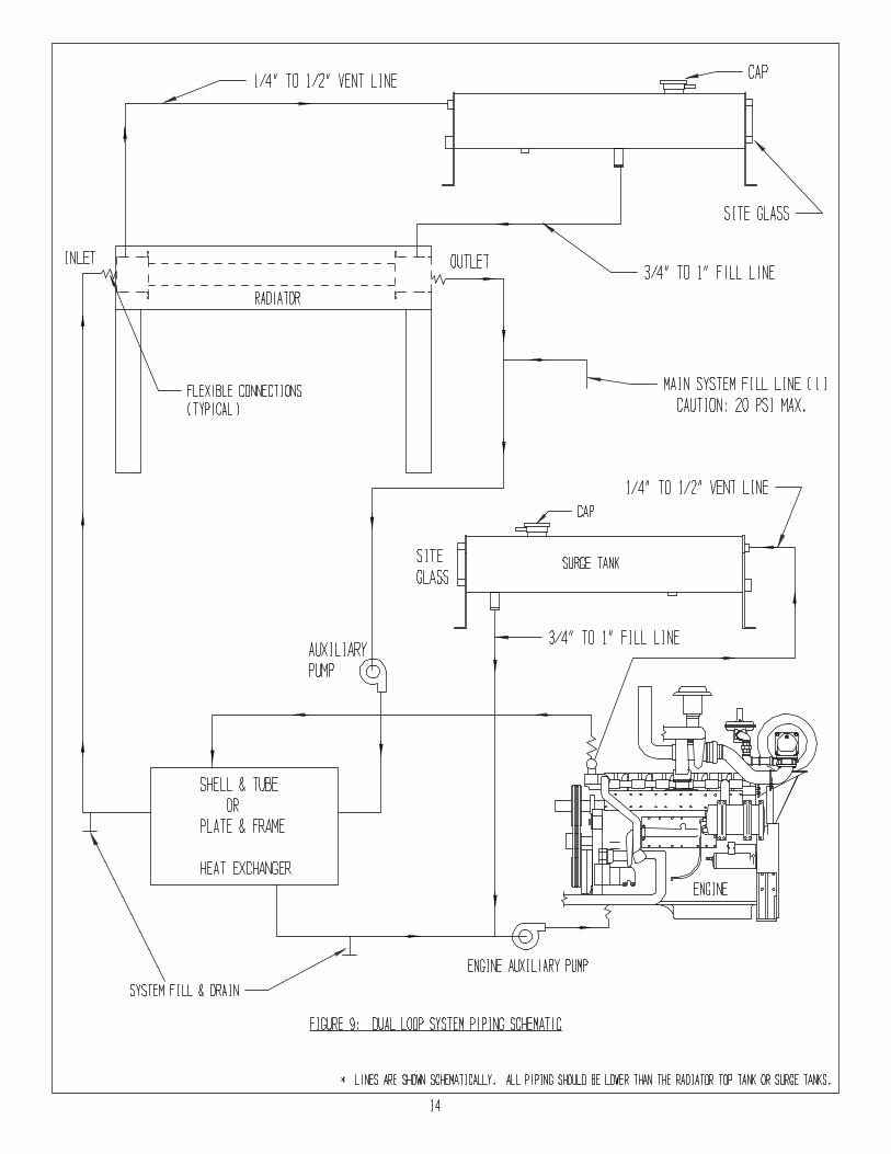
4. DUAL-LOOP SYSTEMS
When a shell and tube or plate and frame heat exchanger is used with a horizontal remote
mounted radiator, dual surge tanks are required and both should be the highest points in
each circuit (see Fig. 9). A 3/4” to 1” (*)fill line should be installed from the bottom of
the radiator surge tank to the radiator outlet tank. A 3/4” to 1” (*)fill line should be
installed from the bottom of the engine surge tank to the pump suction piping. A 1/4” to
1/2” (*)vent line should be installed from the radiator inlet tank to its’ surge tank.
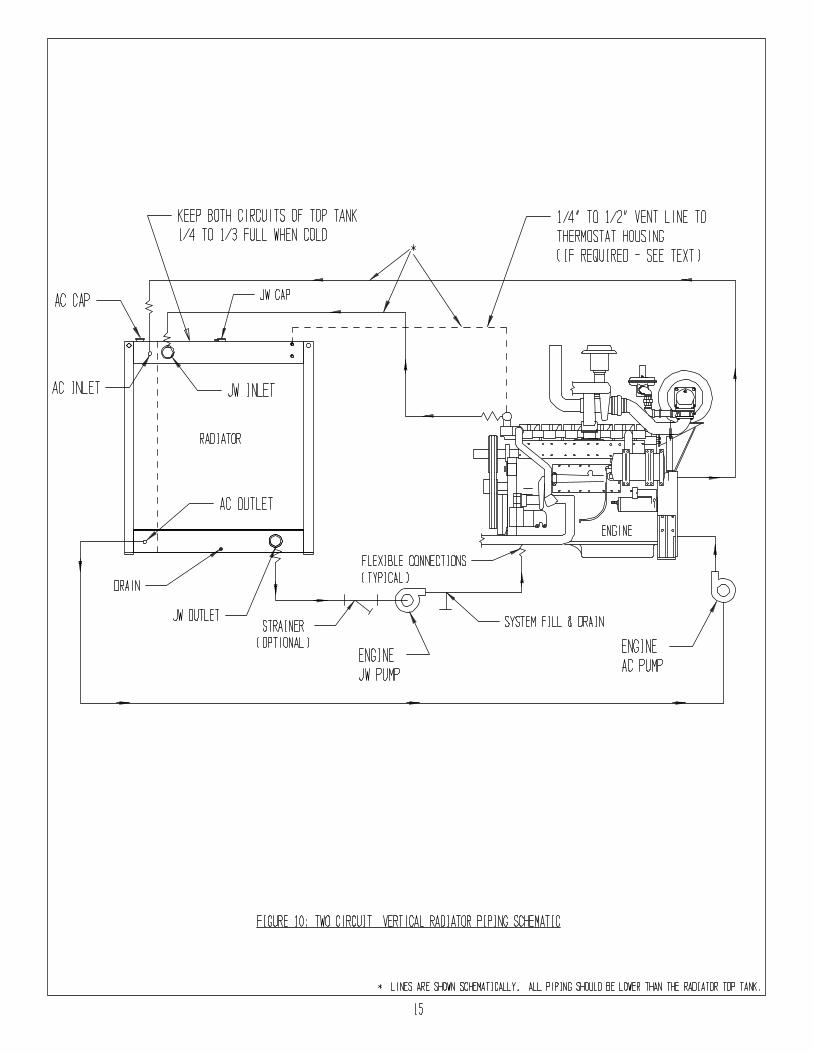
5. TWO-CIRCUIT RADIATORS
When a vertical remote radiator is used as a two-circuit radiator, it should be piped as in
Fig 10. When low flow in the aftercooler circuit requires a two-pass arrangement, both
the inlet and outlet will be in the bottom tank. The radiator top tank must be the highest
point in the system. A 1/4” to 1/2” (*)vent line may be required from the engine
thermostat housing to the jacket water side of the top tank.
When a horizontal remote radiator is used as a two-circuit radiator, it should piped as in
Fig. 11. A surge tank is required for both circuits and both are piped to their respective
outlet tanks. The surge tanks must be the highest points in each circuit. A 1/4” to 1/2”
(*)vent line from the surge tank to the inlet tanks is recommended for both circuits. A
1/4” to 1/2” (*)vent line from the thermostat housing to the jacket water surge tank is
required when the engine is higher than the radiator. The customer should install a drain
valve at the lowest point in each circuit.
6. ALL REMOTE MOUNTED RADIATORS
Flexible connections are required at all of the radiator connections. Strainers are
recommended for initial startup. An auxiliary booster pump may be required depending
on the installation such as distance from the engine, length of pipe, radiator elevation,
quantity and type of fittings, etc. Flexible connections, vent lines, strainers, and auxiliary
pumps are customer supplied.
(*)Size of vent lines or filling lines is dependent on engine size and engine manufacturer’s
recommendations.
12


D. ELECTRICAL WIRING
1. All electric motors are wired per the National Electrical Code. Refer to the radiator
assembly drawing for the correct fan rotation and air flow direction.
2. When a temperature switch is used for fan motor starting, it should be connected to the
radiator inlet, not the radiator outlet.
3. A deceleration control modification must be added to multi-speed magnetic starters when
using two-speed motors. Deceleration control automatically provides, by use of a timer,
motor deceleration when changing from high speed to low speed. The timer allows the
motor to decelerate from high speed to a lower speed before automatically restarting the
motor in low speed. Lack of deceleration control can lead to burned motor windings,
which are not covered under Rocore’s warranty.
4. CAUTION! Make sure that the power source voltage matches the motor nameplate
voltage.
5. WARNING! Disconnect all power sources before initiating any maintenance or repair.
6. WARNING! Make sure unit is electrically grounded in accordance with code
requirements.
E. COOLANT LEVEL SWITCHS
To add a coolant level switch to a radiator, see Fig. 12 or 13.
If you are using a vertical radiator, the installation is made as shown in Fig. 12. The top
connection of the switch is piped to the lowest acceptable coolant level port in the top
tank. The lower connection is piped to a drain port in the radiator bottom tank. The lower
connection should not be close to the radiator outlet.
If you are using a horizontal radiator or a vertical radiator with a surge tank, the level
gauge is installed on the surge tank as shown in Fig. 13. Both the top and bottom
connections are piped into the high and low ports of the surge tank.
F. FILLING
Caution! Do not fill the radiator or surge tank all the way to the top because as the
system heats up, the coolant will expand and hot coolant or steam will be forced out of
the overflow hose. When the system heats up and the coolant expands, the tank should
be 2/3 to 3/4 full. This reserves 1/4 to 1/3 the tank volume for any system surges.
The coolant level should be checked after initial startup to account for any air pockets
created during initial filling. Add coolant as required.
Use good clean water for filling. Water should be neutral or slightly alkaline. Water
should be treated with a reputable inhibitor. If a permanent type anti-freeze is used, the
inhibitor and the anti-freeze must be compatible.
17


See the engine manufacturer’s manual for recommended coolants and maintenance.
For radiators with top tank deaeration baffles, the radiator may need to be filled through
one of the inlets in addition to filling above the deaeration baffle, unless the radiator is
supplied with a special fast-fill port.
G. FAN DRIVE COMPONENTS
When your radiator is supplied with a V-belt driven fan, the belt tension will need to be
checked frequently by the customer. On remote radiators, belts and sheaves are installed
by Rocore. On some engine-mounted radiators, belts and sheaves may be mounted by
the customer. For customer mounted fan drive components, here are some pointers to
keep in mind when installing the drive.
1. Make sure that all sheaves are aligned correctly (see Fig.14). Use a long level or straight
edge to check alignment.
2. Place the belts on the sheaves. Then tension the drive on the slack side of the belts with
the idler until the belts begin to tighten (see section III. B. for correct belt tension).
3. After the first 24 hours of operation, when the belts have had a chance to seat in the
grooves, re-check the belt tension.
4. Use of a tachometer to check for proper fan speed is an alternative to checking belt
tension.
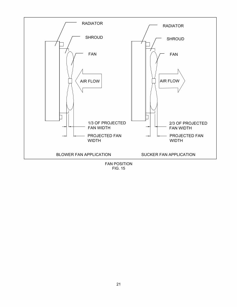
H. FAN POSITION
For engine-mounted radiators that use the engine-mounted fan for cooling, the fan must
be correctly positioned in the radiators fan shroud opening, to obtain optimum fan
performance. The projected blade width needs to be 1/3 (for blower fan applications) or
2/3 (for sucker fan applications) into the fan shroud opening (see Fig. 15).
I. STARTUP
WARNING! Inspect the fan before startup to make sure the blade tips do not hit the
shroud, fan ring or fan guards. Also inspect all moving parts (such as fans, shafts,
motors, sheaves and belts) for damage and/or loose bolts.
WARNING! Make sure that no foreign material or loose parts are in or near the air
stream, fan or other moving parts.
WARNING! As part of initial startup, check that the fan rotation and airflow direction
conform to the radiator assembly drawing.
WARNING! During initial startup, thoroughly check for excessive vibration, noise or
leaks.
19

FAN POSITIONFIG. 15
21
RADIATOR
SHROUD
FAN
AIR FLOW AIR FLOW
1/3 OF PROJECTED
FAN WIDTH2/3 OF PROJECTED
FAN WIDTH
PROJECTED FAN
WIDTH
PROJECTED FAN
WIDTH
BLOWER FAN APPLICATION SUCKER FAN APPLICATION
RADIATOR
SHROUD
FAN

III. GENERAL MAINTENANCE
The following are the maintenance duties that must be done to insure top performance and avoid
hazards.
A. LUBRICATION
1. PILLOW BLOCK BEARINGS
Some radiators are equipped with bearings that require frequent greasing, depending on
the application (see table below).
Application Greasing Frequency
40 Hours a Year Every Six Months
18 Hours a Day Twice a Month
18 Hours a Day
(Dirty Environment) Once a Week
24 Hours a Day Once a Week
24 Hours a Day
(Dirty Environment) Daily
When lubricating the pillow block bearings, it is recommended that the housing be filled
until a bead of grease starts to come out around the seals. Do not use excessive pressure,
as this can damage the bearing seals. Do not mix grease types.
Grease compatibility is critical. Relubricate with grease that is compatible with grease
supplied from the factory. Rocore uses a lithium-based grease (Mobil Mobilux EP-2).
2. MOTOR BEARINGS
Some small motors have sealed-for-life ball bearings, which require no relubrication.
Regreasable bearings are shipped with a high quality, wide temperature-range grease in
the bearings.
Motors should be regreased while warm. Stop the motor, remove the drain plug and
using a low-pressure grease gun, pump in the recommended grease. Run motor for
several minutes to discharge excess grease. Replace drain plug. NOTE: Bearings and
grease must be kept free of dirt.
Units that operate at speeds greater than 1800 RPM should be lubricated on a more
frequent maintenance schedule depending on duty cycle. Use a low-pressure grease gun.
NOTE: Avoid over greasing since damage to and/or overheating of the bearings may
result.
22

SUGGESTED MOTOR REGREASING INTERVALS
MOTOR HORSEPOWER
SERVICE UNDER 50 50-100 100 UP
A 3-5 YEARS 2-4 YEARS 2 YEARS
B 2-4 YEARS 1-1/2 YEARS 1-1/2 YEARS
C 1-1/2 YEARS 1 YEAR 6 MONTHS
D 4 MONTHS 4 MONTHS 3 MONTHS
SERVICE
SYMBOL
TYPE OF SERVICE
A Infrequent operation or light duty in clean atmosphere
B 8-16 Hrs/Day in clean, relatively dry atmosphere
C 12-24 Hrs/Day, heavy duty, or if moisture is present
D Heavy duty in dirty, dusty locations: high amblents; moisture laden atmosphere; vibration
RECOMMENDED MOTOR BEARING GREASES
Use the following greases or equivalent grease unless a special grease is specified on the
nameplate.
MANUACTURER TRADE NAME
CHEVRON SRI #2
SHELL DOLIUM R
B. BELT TENSION
When your radiator is supplied with a V-belt driven fan, the belt tension will need to be
checked frequently. Proper belt tension is necessary for normal belt and bearing life and
to provide the required radiator cooling performance.
See Section II. G. for installation of fan drive components (including V-belts) to be
installed by the customer. On remote radiators, the belts and sheaves are initially
installed and properly tensioned by Rocore.
In either case, the V-belts should be tensioned to the deflection forces as shown in the
following table:
23

DEFLECTION FORCE FOR BELT TENSION
FOR SUPER GRIPBELTS AND GRIPNOTCH BELTS
BELT DEFLECTION FORCE – LBS
SUPER
GRIPBELTS
GRIPNOTCH
BELTS
BELT CROSS
SECTION
SMALLEST
SHEAVE
DIAMETER
RANGEUSED
BELT
NEW
BELT
USED
BELT
NEW
BELT
B 5.8 – 8.6 6.3 9.4 8.5 12.6
C 7.0 – 9.0
9.5 – 16.0
11.5
14.1
17.0
21.0
14.7
15.9
21.8
23.5
5V 7.1 – 10.9
11.8 – 16.0
12.7
15.5
18.9
23.4
13.7
17.1
22.1
25.5
The deflection force in the above table should be measured at the mid-point of the belt
span (distance between two sheave centerlines) with a belt tension checker. For more
detailed instructions, follow the belt tension checker’s instructions.
New drives should be tensioned close to the maximum recommended deflection force.
Check the tension frequently during the first 24 to 48 hours of operation. The ideal
tension is the lowest tension at which the belts will not slip under peak load conditions.
WARNING! Over-tensioning belts shortens belt and bearing life.
WARNING! Under-tensioning belts can cause the following:
- premature belt wear
- reduced radiator cooling performance as a result of slower fan speed
- fan failure. Some types of fans may have critical or resonant
frequencies that must be avoided.
Use of a tachometer to check for proper fan speed is an alternative to checking belt
tension.
Check the belt tension or fan speed regularly and re-tension if required.
CAUTION! Never apply belt dressing, as this will damage belts and cause early failure.
C. BOLTS AND TORQUE REQUIREMENTS
All bolted joints are properly torqued at the factory and the cooler’s gasketed joints are
leak tested.
Before initial startup and as a regular preventive maintenance procedure, the radiator
should be thoroughly inspected for loose bolts.
24

A typical Rocore radiator may have many different types of bolted joints and torque
requirements (see below).
1. SOFT JOINT TORQUE REQUIREMENTS
These are the cooler’s tank/gasket/header joints. Upon the initial filling of the radiator,
you may notice some slight seepage around the gasket joints. This is due to the gasket
drying during shipping and/or storage. If this occurs, allow the gaskets to soak overnight.
The gaskets may swell enough to stop the leaking. If not, the bolts will need to be
re-torqued.
Remove the fan or core guards in the area of the leak. Start re-torqueing these bolts from
the center of each side of each header and continue moving outward. All header bolts
should be re-torqued at this time. The torque for these bolts should be 13 to 15 ft-lbs.
Then replace the guards. CAUTION! Do not over-torque. Over-torqueing may damage
the gasket.
2. STANDARD HARD JOINT TORQUE REQUIREMENTS
Standard hard joints would be defined as metal-to-metal joints that are assembled with
standard hex bolts, nuts and washers. If any of the standard hard joints require
re-torqueing, use the following values:
DRY TORQUE, FT – LBS
BOLT SIZE GRADE 5 GRADE 8
1/4 – 20 8 12
5/16 –18 17 25
3/8 – 16 30 45
1/2 –13 75 110
5/8 – 11 150 220
3/4 – 10 260 380
3. STEEL BUSHING TORQUE REQUIREMENTS
For steel bushings to steel sheave hubs and steel fan hubs use the following values. The
bushing type is usually stamped on the bushing.
BUSHING TYPE BOLT SIZE TORQUE, FT – LBS
H 1/4 - 20 X 3/4 8
SH, SDS 1/4 - 20 X 1 3/8 9
SD 1/4 - 20 X 1 7/8 9
P1, P2, P3 5/16 – 18 X 1 16
SK 5/16 – 16 X 2 15
Q1, Q2, Q3 3/8 –16 X 1 1/4 29
R1, R2 3/8 – 16 X 1 3/4 29
SF 3/8 – 16 X 2 30
S1, S2 1/2 - 13 X 2 1/4 70
E 1/2 - 13 X2 3/4 60
F 9/16 – 12 X 3 5/8 75
25

4. SPECIAL JOINT TORQUE REQUIREMENTS
Any joints not covered by the above, such as special fasteners or special materials such as
aluminum fan hub or fan blade bolts may require special torque requirements. If any of
these type joints require attention, consult Rocore engineering.
D. CORE CLEANING
The cooler cores may become clogged with leaves, paper, or dirt, or may become coated
with oil or dust. Any of these conditions may result in reduced cooler performance.
Cleaning the core can be done with compressed air, steam, or water spray, but caution is
necessary to not use high pressure close to the core, because the core fins are very
delicate and can be bent or damaged.
E. REPLACEMENT PARTS
If it becomes necessary to replace any parts, please record all the radiator nameplate
information, such as part no., serial no. and mfg. date.
F. MISCELLANEOUS
The coolant level should be checked regularly and maintained at all times.
Regularly inspect for excessive vibration or noise.
Regularly inspect for loose or missing fasteners, especially on or near moving parts.
Regularly inspect fans and guards for signs or fatigue (cracks, and loose or missing
fasteners).
26

INDUSTRIES, INC.
LIMITED WARRANTY
Rocore Industries, Inc., hereafter referred to as the “Company” warrants its products against
defects in material and workmanship under normal use and service for a period of one year from
date of shipment from its plant of manufacture, except as noted, trucks and buses are 100,000
miles or one year which ever is first.
All obligations and liabilities under this warranty are limited to repairing or replacing, at the
Company’s option, such allegedly defective products or parts as are returned, carrier charges
prepaid by the buyer to the plant. All such repairs or replacements are made subject to
inspection for warranty coverage by the Company of the returned products or parts at the
Company’s plant. No liability is assumed for costs relating to removal or reinstallation of the
Company’s product.
Warranty on components or accessories furnished by suppliers to the Company shall be limited
to the warranty of the respective component or accessory supplier.
If field service at the request of the Buyer is rendered by the Company, and the alleged fault is
found not to be with the Company’s product, component or accessory, the Buyer shall pay for
the time and expenses of the field representative. Bills for service, labor or other expenses that
have been incurred by the Buyer, their customer or agent without approval or authorization by
the Company, will not be accepted.
This warranty does not cover failure resulting from improper installation, mounting design or
application data supplied by the Buyer, nor does it cover failure due to the effects of physical or
chemical properties of water, steam, and other liquids or gases used in the products. The
Company’s products are not packaged or protected for long periods of storage in generally
corrosive atmospheric conditions. Damage from these conditions are not covered by the limited
warranty.
Changes or repairs attempted or made in the field without written authorization from the
Company automatically void this warranty.
The Company, whose policy is one of continuous improvement, reserves the right to improve its
products through changes in design or material as it may deem desirable without being obligated
to incorporate such changes in products of prior manufacture.
Buyer acknowledges that the company and its distributors are not liable to Buyer or those
claiming through Buyer for any damages whatsoever resulting from the alleged breach of the
Company’s representations contained in this limited warranty. Buyer further acknowledges that
Company makes no warranty or guaranty, express or implied, as to the merchantability, fitness,
design, performance, capacity or efficiency of any product sold by Company, and that Company
shall not be liable for any special, indirect, consequential or incidental damages for negligence of
other tort, breach of contract or warranty or otherwise resulting from failure of machinery or
equipment.