installation, operation and maintenance instructions · track control. control of the ... 20ma dc...
TRANSCRIPT

11
N12- G & HW Series Frequency Controllers 115/230VAC
Installation, Operation and MaintenanceInstructions
VM-10A
ERIEZ HEADQUARTERS: 2200 ASBURY ROAD, ERIE, PA 16506–1402 U.S.A.WORLD AUTHORITY IN SEPARATION TECHNOLOGIES
N12- G & HW SERIES FREQUENCY CONTROLLERS 115/230VAC FOR 30, 40, 50 & 60HZ ELECTROMAGNETIC FEEDERS
compliant controllers

2
WArning ........................................................................................................................4.
Technical Data ............................................................................................................4.
insTAllATion ............................................................................................................ 5-6.
Mounting .....................................................................................................................5
Wiring ..........................................................................................................................5
Connections ...............................................................................................................5
set-up .........................................................................................................................5
Adjustments................................................................................................................5
Parameter Adjustment Procedure .............................................................................6.
ConTrol ElEMEnTs ............................................................................................... 7-8.
settings ................................................................................................................... 7-8.
CoMMissioning ..................................................................................................... 9-10
Preliminary steps .......................................................................................................9
important Points .........................................................................................................9
operating Frequency of the Feeder Coil ..................................................................9
Measurement of the output Voltage and Current ....................................................9
Adjustments................................................................................................................9
Putting the Equipment into operation .......................................................................9
Table of ContentsERIEZ p-REx dRuM MAGNET

3
N12- G & HW Series Frequency Controllers 115/230VAC
Table of Contents (cont.)
sETTing insTruCTions .....................................................................................10-17
user Enable, remote on/oFF ............................................................................. 10
user Adjustment of Throughput...............................................................................11
Tuning the Feed system Feeder settings ..............................................................11
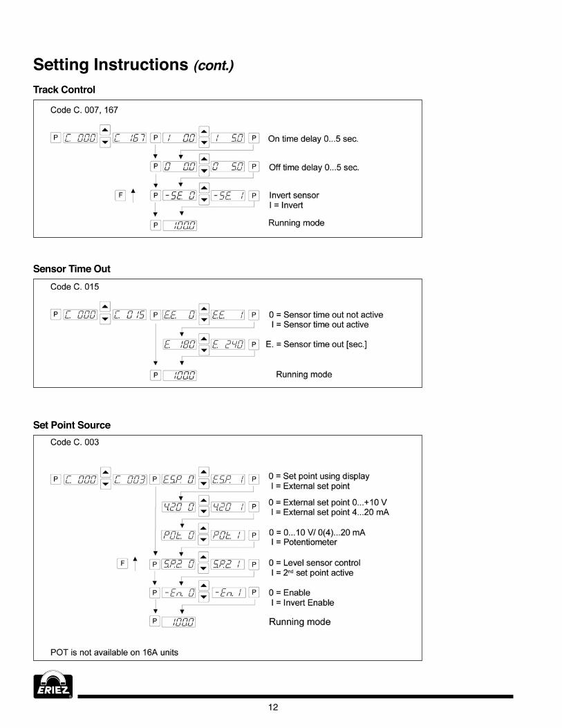
Track Control ........................................................................................................... 12
sensor Time out ..................................................................................................... 12
set Point source ..................................................................................................... 12
regulation Mode ..................................................................................................... 13
instructions for using regulation Mode ................................................................. 13
Mounting the Accelerometer ................................................................................... 14.
relationship Between Acceleration and Amplitude ............................................... 15
instructions for setting up the Controller in regulation Mode ............................... 15
Determining the resonant Frequency ................................................................... 15
optimisating Controller in regulation Mode .......................................................... 15
Displays ................................................................................................................... 16.
Display Actual Current and Frequency .................................................................. 16.
save selected Parameters ..................................................................................... 17
recall user or Factory settings .............................................................................. 17
Hide Parameter Menus ........................................................................................... 17
Error MEssAgEs / Error rEsET ..................................................................... 18.
FAulT TrouBlEsHooTing ......................................................................................19
Troubleshooting - Frequency Controllers ............................................................... 19
TrAy rEgulATion MoDE sETuP WiTH loCAl sETPoinT ............................... 20
ExTErnAl sETPoinT MoDE WiTH rEMoTE 4.-20MA sETPoinT ...................... 20
TrAy rEgulATion MoDE WiTH rEMoTE 4.-20MA sETPoinT .......................... 21
TECHniCAl DrAWings ........................................................................................22-23
4.
General description
Technical data
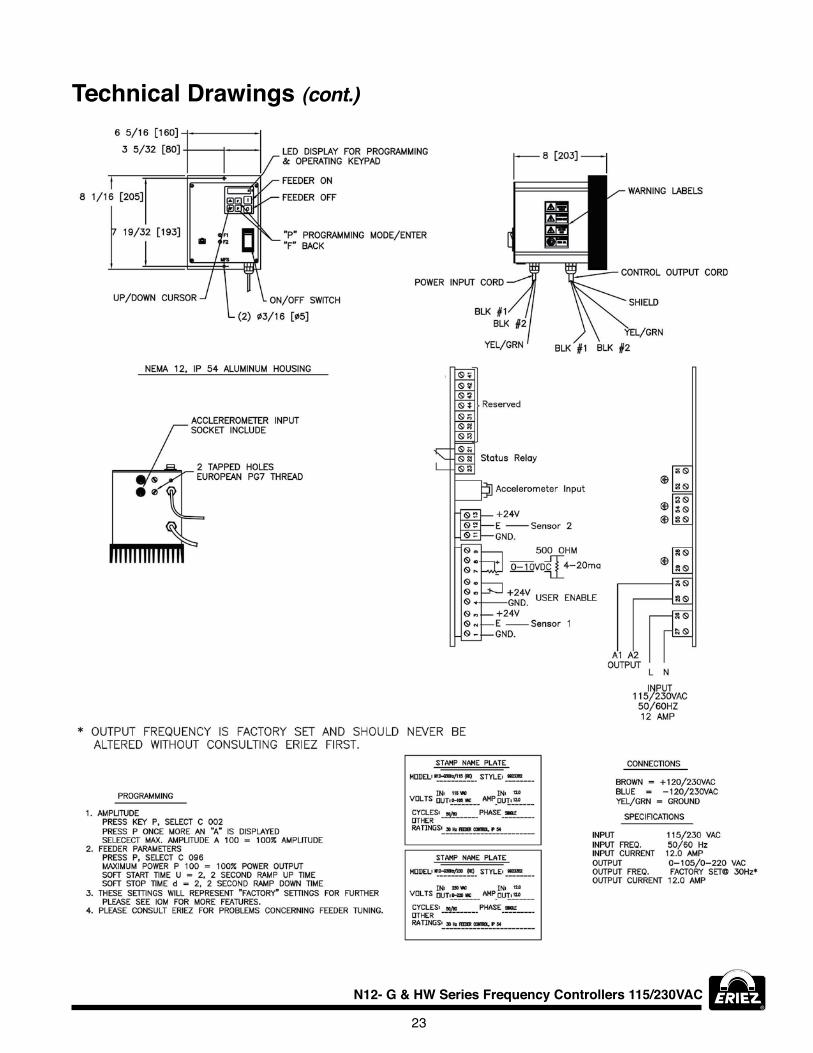
WARNINGThis control is capable of variable output voltage over a wide range of frequencies. This model should only be run at the factory set frequency. If modification in output frequency is needed, we suggest that the user contact Eriez first. After switching unit off, some components may still be charged due to capacitance. Wait at least five (5) minutes before opening the cover to allow capacitors to discharge.
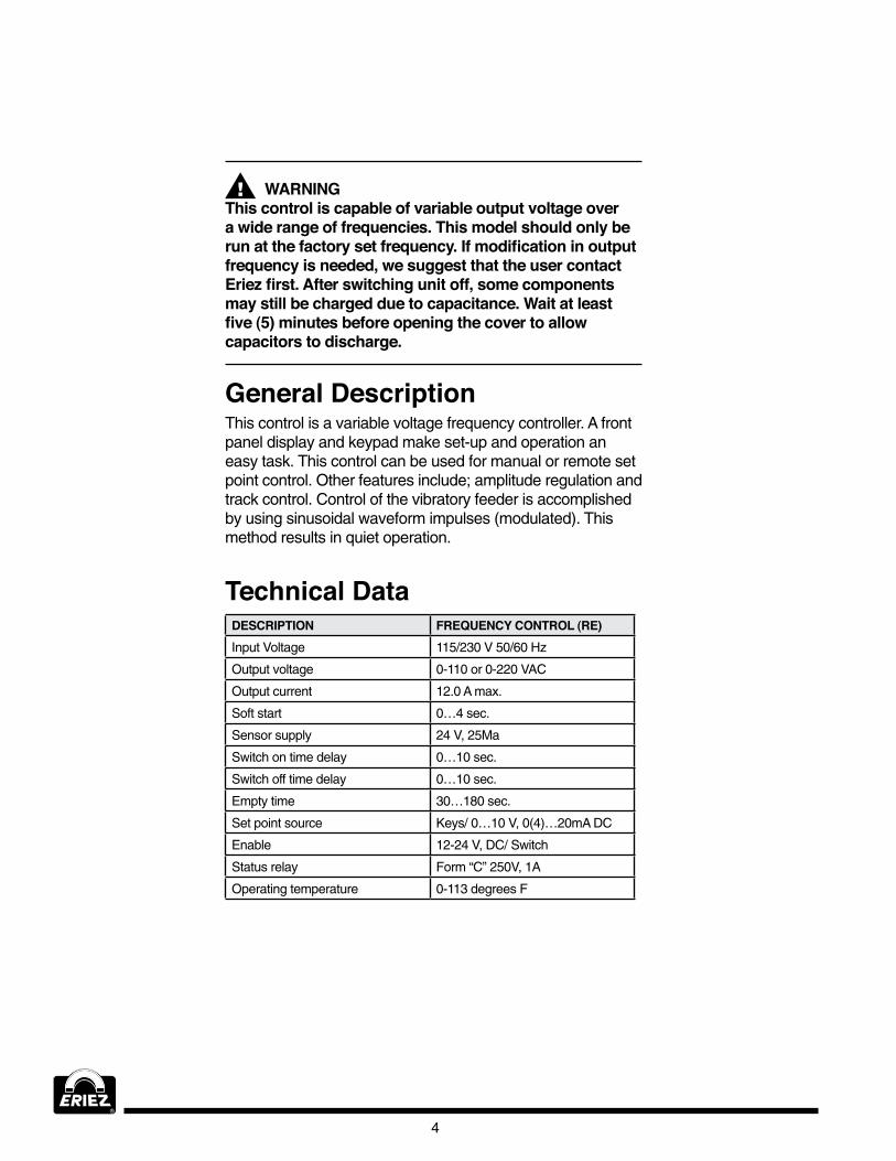
This control is a variable voltage frequency controller. A front panel display and keypad make set-up and operation an easy task. This control can be used for manual or remote set point control. other features include; amplitude regulation and track control. Control of the vibratory feeder is accomplished by using sinusoidal waveform impulses (modulated). This method results in quiet operation.
dESCRIpTION FREquENCy CONTROl (RE)input Voltage 115/230 V 50/6.0 Hz
output voltage 0-110 or 0-220 VAC
output current 12.0 A max.
soft start 0…4. sec.
sensor supply 24. V, 25Ma
switch on time delay 0…10 sec.
switch off time delay 0…10 sec.
Empty time 30…18.0 sec.
set point source Keys/ 0…10 V, 0(4.)…20mA DC
Enable 12-24. V, DC/ switch
status relay Form “C” 250V, 1A
operating temperature 0-113 degrees F

5
N12- G & HW Series Frequency Controllers 115/230VAC
MountingThe controller should be mounted in a reasonably dry, minimum dust area, if possible, where the ambient temperature does not exceed 100°F. it is designed for vertical mounting. refer to the supplied schematic and outline drawing for mounting dimensions. The mounting site should be relatively free of vibration or steps should be taken to isolate the unit.
Wiringrefer to the supplied schematic and outline drawing for connections. The installation of a fused safety switch or branch circuit breaker ahead of the controller is recommended.
Connectionsinput Cable 120/230 VAC supply voltage
output Cable output - Eriez feeder
Set-upusing the buttons and the lED display located on a touch plate on the front panel sets up this unit. The feeder throughput adjustment and setting of other parameters can be carried out by using these components. The control can also be operated by external means, such as potentiometers and signal sources. The parameters can be changed by scrolling through the menu, which is accessed by a user password. The various functions within the menu are identified with capital letters for ease of recognition. Enable and fault contacts are located inside the control enclosure along with other user connection points. The output power is shown in percent (%) on the lED display during normal operation. Changed settings are saved when leaving programming mode or after a 100 second delay from when the last key was pressed.
Installation Adjustments•soft start ramp up time 0,1…4. sec.
•soft stop ramp down time 0,1…4. sec.
•Maximum control limit (umax)
•Minimum control (umin)
•Changeover for using an external set point source 0…10VDC (or Potentiometer)/0…20mA, 4.…20mA
•switch on time delay (for track control)
•switch off time delay (for track control)
• invert sensor function
•Empty time delay, if the material sensor does not see product
•return to factory settings

6.
parameter Adjustment procedure
1. Amplitude adjustmentPress the programming Mode key (P)
observe a “C 000” in the display
using Cursor keys select “C 002”
Press P key, observe “A 000”
now an amplitude setting in percent can be entered
Press P key to return controller to normal operation
2. Other feeder valuesPress P key, using cursor key move to “C 096.”
Press P key to select required parameter
“A 000” = Amplitude (Feeder) [%]
“P 000” = Maximum control limit [%], adjustable 20…100%
“Ґ 000” = soft start time
“l 000” = soft stop time [sec.], operates when unit switched off by track sensor
Press P key to return to programming mode
3. Set source and output waveformPress P key, using cursor key move to “C 003”
Press P key to select required parameter
“E.s.P.” = external set point, 0 for keys, 1 for external
if 1 is selected, control will operate with potentiometer. if remote potentiometer is used sET Amplitude “A” to 0%. Bias upward by raising amplitude level.
if 1 is selected, press P key and select “4..20 0”
select 1 for set point values 0…10 v, dc or 0…20mA
select 0 for set point values 4.…20mA DC
Press P key to select “sP.2 0” for track control mode and “sP.2 1” for dual set point operation
output waveform is factory set and should not be adjusted
Please consult Eriez for more information concerning Track Control.
Installation (cont.) 4. Return to saved settingsPress P key, using cursor key move to “C 210”
Press P key to select required parameter
“FAC” = factory settings, using cursor key select “sAFE” (loads factory settings)
Press P key to observe “usPA”, using cursor key select “sAFE” (return to user parameters)
Press P key to return to normal operating model
5. Storing user parametersPress P key, using cursor key move to “C 14.3”
Press P key to select required parameter
“PusH” = save parameters, using cursor key select “sAFE” (parameters are saved)
Press P key to return to normal operating model
6. When an "OFF" is displayed and will not cleargo to code "003" and select En=1
if control is wired for remote, the remote switch should be closed or a jumper placed between term's 5 and 6. (user enable).
7
N12- G & HW Series Frequency Controllers 115/230VAC
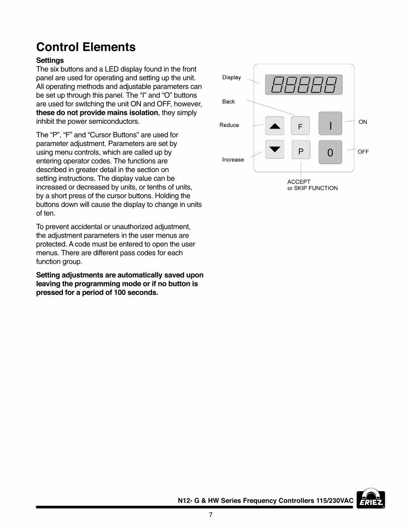
Control ElementsSettingsThe six buttons and a lED display found in the front panel are used for operating and setting up the unit. All operating methods and adjustable parameters can be set up through this panel. The “i” and “o” buttons are used for switching the unit on and oFF, however, these do not provide mains isolation, they simply inhibit the power semiconductors.
The “P”, “F” and “Cursor Buttons” are used for parameter adjustment. Parameters are set by using menu controls, which are called up by entering operator codes. The functions are described in greater detail in the section on setting instructions. The display value can be increased or decreased by units, or tenths of units, by a short press of the cursor buttons. Holding the buttons down will cause the display to change in units of ten.
To prevent accidental or unauthorized adjustment, the adjustment parameters in the user menus are protected. A code must be entered to open the user menus. There are different pass codes for each function group.
Setting adjustments are automatically saved upon leaving the programming mode or if no button is pressed for a period of 100 seconds.
8.
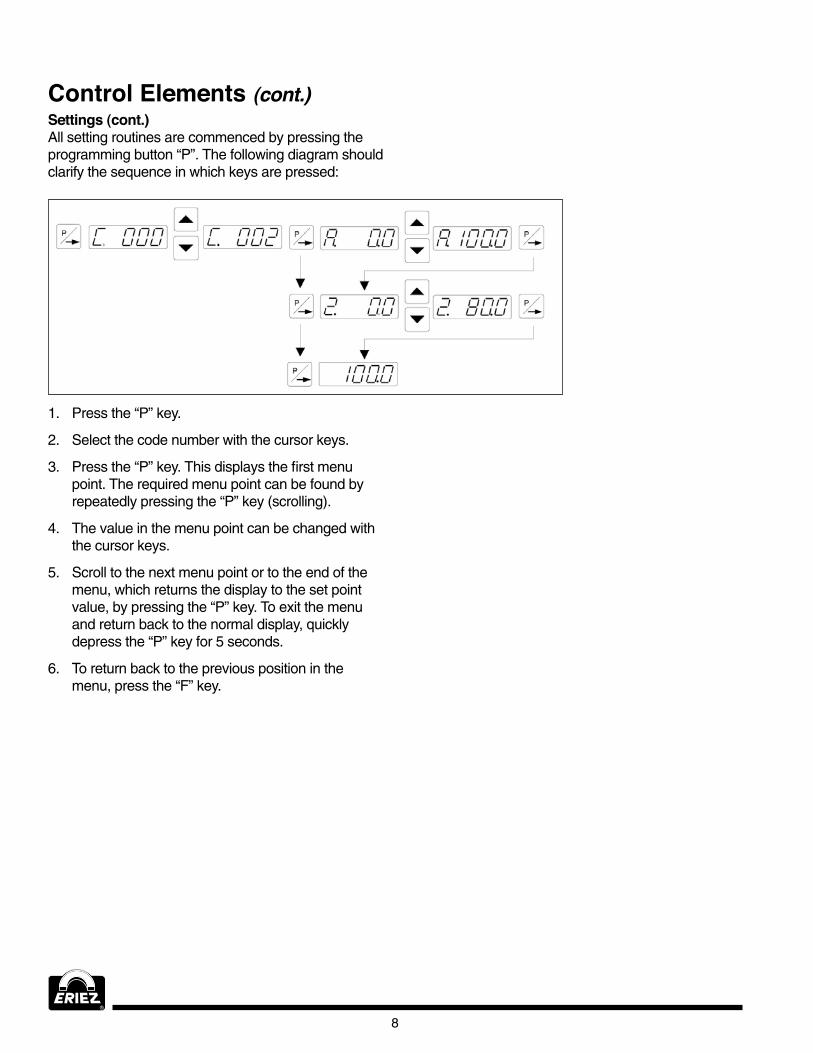
Control Elements (cont.)Settings (cont.)All setting routines are commenced by pressing the programming button “P”. The following diagram should clarify the sequence in which keys are pressed:
1. Press the “P” key.
2. select the code number with the cursor keys.
3. Press the “P” key. This displays the first menu point. The required menu point can be found by repeatedly pressing the “P” key (scrolling).
4.. The value in the menu point can be changed with the cursor keys.
5. scroll to the next menu point or to the end of the menu, which returns the display to the set point value, by pressing the “P” key. To exit the menu and return back to the normal display, quickly depress the “P” key for 5 seconds.
6.. To return back to the previous position in the menu, press the “F” key.

9
N12- G & HW Series Frequency Controllers 115/230VAC
Commissioningpreliminary Steps
•Check that the unit is correct for the local mains supply (rating plate information) and that it is correctly rated for the feed system.
•Connect the controller according to the connection diagram.
Important pointsusing the control units described in this document, it is possible to adjust the feed system so that it runs at resonance. in this
condition, it is possible to obtain excessive output for a very low set point setting. Therefore, extreme care should be taken to avoid causing damage to the drive coil through hammering.
in practice, it is not possible to run at resonant frequency without accelerometer feedback because the system would be unstable and uncontrollable. The system must be set safely off resonance i.e. either above or below the natural frequency.
Resonant frequency: Depending on the spring and mass design of the feeder system, it is possible to have resonance at more than one frequency. These additional resonance points are multiples of the main frequency. For this reason, in critical situations, it is possible that the automatic frequency search will not find true resonance and in such cases the natural frequency must be determined manually.
Operating Frequency of the Feeder Coilit is possible that the current flowing through the coil will increase for a small frequency adjustment. so this should be checked with a true rMs instrument for each new application as well as monitoring the coil for heat build-up.
The coil should be designed for the correct operating frequency to prevent excessive current draw and the consequential overloading of the coil.
Measurement of the Output Voltage and CurrentThe voltage and current cannot be measured with a regular instrument because the controller output uses an electronic inverter with a pulse width modulation signal. An effective measuring instrument such as a moving iron meter (analog) must be used. it is recommended that an analog instrument is used rather than an electronic multi-meter which will give a misleading reading.
putting the Equipment into Operation1. Establish the vibrating frequency.
2. Establish the power of the feed system (maximum permissible current draw).
For a new feeder where settings are unknown (see also comments below).
Without connecting the feeder, select parameter FAC in menu C210 (reset factory settings), press the cursor key to reset (sAFE) and press the P key to leave the menu. The factory settings are listed in the table in section 7, headed settings.
! Comments !it is possible that a special parameter set, for a machine manufacturer, has been pre-stored under a user code and these can be recalled. in such instances, specific machine settings will be loaded and so the next steps are not relevant.
Basic settings:
•Connect feeder.
•set frequency (refer to feeder data sheet). Menu C096. parameter F.
•Check current limit (refer to feeder data sheet). Menu C04.0 parameter i (shows the current limit as a percentage of maximum). if applicable, use service menu for setting.
• increase set point, observe feeder, check running.
• increase set point to maximum and check if power needs limiting (hammering). if necessary, adjust the limit as follows:
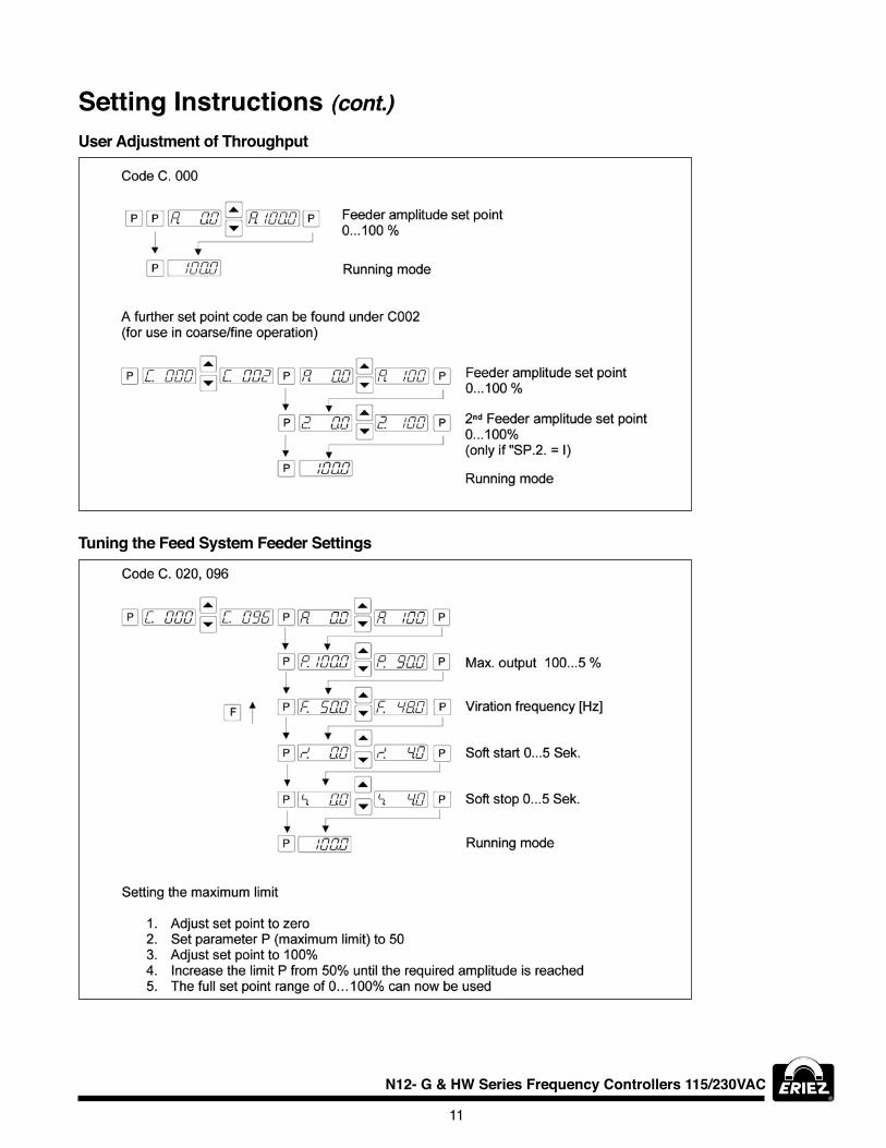
•Adjust set point to zero.
•set parameter P (maximum limit) in Menu C096. to 50.
•Adjust set point A to 100%.
• increase the maximum limit P from 50% until the required amplitude is reached.
•The full set point range of 0…100% can now be used.
Additional settings e.g. soft start, time delays etc. can be set to suit the particular equipment.

10
Commissioning (cont.)
Setting Instructionsuser Enable, Remote ON/OFF
determining the output frequency (vibrating frequency)it is essential that the output frequency is adjusted with the set point set at a low frequency, otherwise on hitting the resonant frequency, it is possible to achieve a high amplitude with a low output voltage. An analog, effective value, current indicating unit (moving iron meter) must be connected into the output circuit.
Resonant is reached when there is a maximum amplitude for a minimum output current. To achieve a stable feed system, there must be an offset between the vibrating frequency and resonance (approx. 1…2Hz). This offset must be determined by the user because different feeders have different running characteristics.
To turn the feeder or conveyor ON/OFF remotely with a contact:refer to the control schematic on page 23 of this ioM.
The wire jumper between terminal 5 and 6. should be removed.
Dry contact to be connected between terminals 5 and 6..
Manual switch on face plate of controls to be in on position.
To turn the feeder or conveyor ON/OFF remotely with a 24V dC signal:refer to the control schematic on page 23 of this ioM.
The wire jumper between terminal 5 and 6. should be removed.
24.V DC signal to be connected to terminal 5 and ground to terminal 4..
Manual switch on face plate of control to be in on position.
11
N12- G & HW Series Frequency Controllers 115/230VAC
user Adjustment of Throughput
Tuning the Feed System Feeder Settings
Setting Instructions (cont.)
12
Setting Instructions (cont.)Track Control
Sensor Time Out
Set point Source
13
N12- G & HW Series Frequency Controllers 115/230VAC
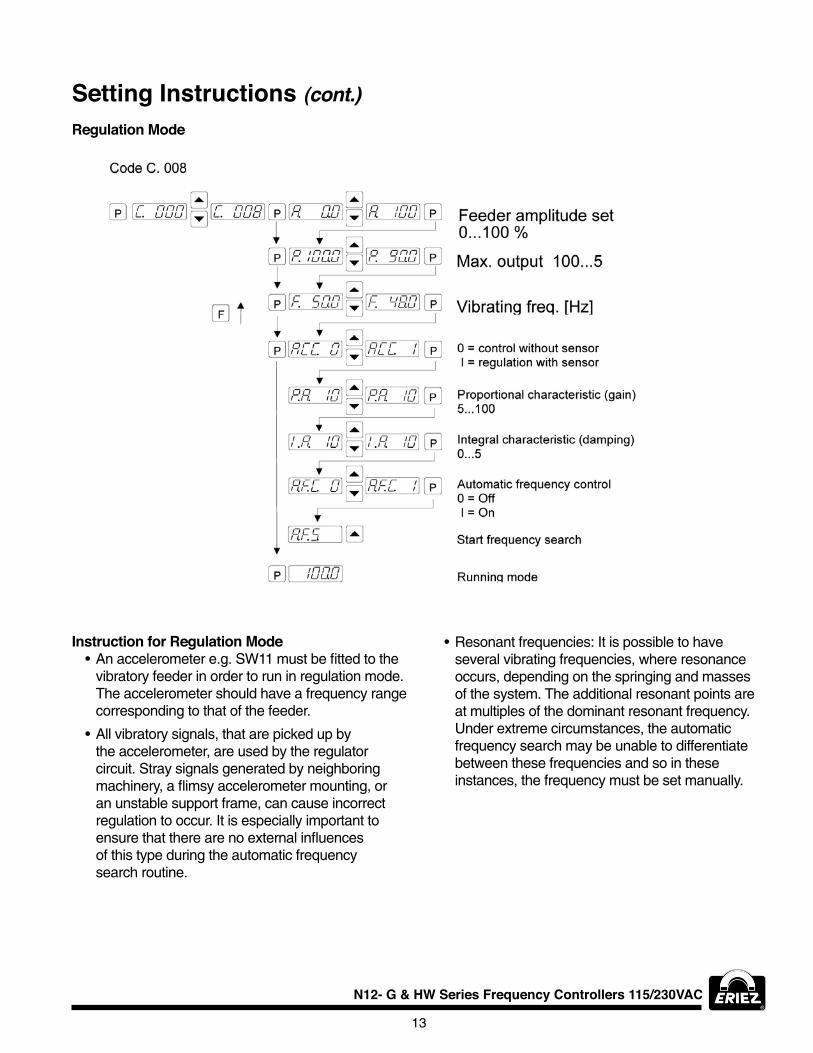
Setting Instructions (cont.)Regulation Mode
Instruction for Regulation Mode•An accelerometer e.g. sW11 must be fitted to the
vibratory feeder in order to run in regulation mode. The accelerometer should have a frequency range corresponding to that of the feeder.
•All vibratory signals, that are picked up by the accelerometer, are used by the regulator circuit. stray signals generated by neighboring machinery, a flimsy accelerometer mounting, or an unstable support frame, can cause incorrect regulation to occur. it is especially important to ensure that there are no external influences of this type during the automatic frequency search routine.
•resonant frequencies: it is possible to have several vibrating frequencies, where resonance occurs, depending on the springing and masses of the system. The additional resonant points are at multiples of the dominant resonant frequency. under extreme circumstances, the automatic frequency search may be unable to differentiate between these frequencies and so in these instances, the frequency must be set manually.

14.
Setting Instructions (cont.)
Bracket Mount(must be rigid and not flex)
Block Mount
or
The controller, together with the sensor fitted on the feeder, produces a feed back loop, whereby the signal generated from the sensor determines the control range of the set point i.e. the regulator controls the feeder so that the effective value (feeder power or intensity of vibration) relates to the provided set point value. Because the effective value is dependent on the feeder (frequency, acceleration and amplitude) and in addition depends on the mounting position of the sensor, the regulator must be adapted to suit the output control range.
linear Feed Example
1. small amplitude because sensor is mounted vertically.
2. larger amplitude because sensor is mounted in the same plane as the springs.
Mounting the AccelerometerThe accelerometer should generate signals for the movement and acceleration of the feeder, which are fed back to the regulator circuit of the control unit. Therefore, it is very important that no other extraneous vibration signals are picked up by the sensor.
The sensor should be positioned so that it moves in the same direction as the feeder, ideally in the same plane as the springs, and it should be fitted on a solid block that will not generate vibration signals.
In regulation mode the magnitude of the output signal has a direct affect on the maximum amplitude of the feeder.
on bowl feeders, it is advisable to fit the sensor as near as possible to the outside diameter and in this position, it will be subjected to the greatest movement.
The control range of the set point will be considerably reduced when the sensor signal is weak.
s = deflection Mounting position 1 = small deflection Mounting position 2 = large deflection
This is achieved by using the parameter P in Menu C 008. The measured sensor signal range is adjusted by changing this value. In most instances, a value of less than 100 must be entered, so that the set point can reach 100% or can go as high as possible. When it is not possible to achieve an acceptable range, the accelerometer should be mounted in the location which gives the greatest movement (see the bowl feeder example).
The importance of scaling this value is demonstrated when, for example, a feeder takes a very long time to ramp up, after it has been switched on.
15
N12- G & HW Series Frequency Controllers 115/230VAC
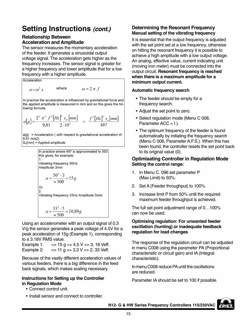
Setting Instructions (cont.)Relationship Between Acceleration and AmplitudeThe sensor measures the momentary acceleration of the feeder. it generates a sinusoidal output voltage signal. The acceleration gets higher as the frequency increases. The sensor signal is greater for a higher frequency and lower amplitude that for a low frequency with a higher amplitude.
using an accelerometer with an output signal of 0.3 V/g the sensor generates a peak voltage of 4..5V for a peak acceleration of 15g (Example 1), corresponding to a 3.18.V rMs value. Example 1: => 15 g => 4.,5 V => 3, 18. Veff. Example 2: => 11 g => 3,3 V => 2, 33 Veff.
Because of the vastly different acceleration values of various feeders, there is a big difference in the feed back signals, which makes scaling necessary.
Instructions for Setting up the Controller in Regulation Mode
•Connect control unit.
• install sensor and connect to controller.
determining the Resonant FrequencyManual setting of the vibrating frequency it is essential that the output frequency is adjusted with the set point set at a low frequency, otherwise on hitting the resonant frequency it is possible to achieve a high amplitude with a low output voltage. An analog, effective value, current indicating unit (moving iron meter) must be connected into the output circuit. Resonant frequency is reached when there is a maximum amplitude for a minimum output current.
Automatic frequency search
•The feeder should be empty for a frequency search.
•Adjust the set point to zero.
•select regulation mode (Menu C 008., Parameter ACC = i ).
•The optimum frequency of the feeder is found automatically by initiating the frequency search (Menu C 008., Parameter A.F.s.). When this has been found, the controller resets the set point back to its original value (0).
Optimisating Controller in Regulation ModeSetting the control range:
1. in Menu C. 096. set parameter P (Max limit) to 50%.
2. set A (Feeder throughput) to 100%.
3. increase limit P from 50% until the required maximum feeder throughput is achieved.
The full set point adjustment range of 0…100% can now be used.
Optimising regulation: For unwanted feeder oscillation (hunting) or inadequate feedback regulation for load changes
The response of the regulation circuit can be adjusted in menu C008. using the parameter PA (Proportional characteristic or circuit gain) and iA (integral characteristic).
in menu C008. reduce PA until the oscillations are reduced.
Parameter iA should be set to 100 if possible.

16.
Setting Instructions (cont.)displays
display Actual Current and Frequency

17
N12- G & HW Series Frequency Controllers 115/230VAC
Setting Instructions (cont.)Save Selected parameters
Recall user or Factory Settings
Hide parameter Menus

18.
Error Messages / Error ResetErrors are indicated by an alternating code and Error display.
Overload limitoutput level exceeded e.g. incorrect frequency setting, coil air-gap to wide.
Short circuit tripFaulty coil, short circuit or defective cable.
Over voltagesupply voltage too high or back EMF from the coil at lower frequencies.
Current spike limitFrequency set too low for installed coil or frequency altered too rapidly during setting up.
Sensor fault (only when regulation mode is selected)Accelerometer not working or faulty.
Error Reset through Menu C009
Sensor time outAfter sensor time out has elapsed.
Error Reset is achieved by pressing touch panel keys 0 or I during normal operation or by using Menu C009.
in the event of an error check that this is not caused by incorrect wiring or cable faults. The error message, Error ACC, can also occur if regulation mode is chosen (in Menu C008.) and an accelerometer is not connected, for example.
reset the error in the following manner:
Error ResetClear Error

19
N12- G & HW Series Frequency Controllers 115/230VAC
pROBlEM pOSSIBlE REASON REMEdy
Feeder does not vibrate incorrect frequency setting resonate frequency search
Feeder hammers when throughput is set high. • Feeder is working too close to its resonate frequency.
• Air gap too small.
• Adjust frequency.• reduce maximum limit [P]
(Menu “C 096.”).• Check air gap (Caution: too big an
air gap increases the current).
Magnet gets warm. • Frequency setting is too low for the coil type.
• Air gap is too large.
• Adjust to a higher frequency or fit a more suitable coil.
• reduce the air gap.
"oFF" displayed and feeder does not run. • no enable signal. • Provide enable signal using contacts of 24.VDC signal.
• Fit a link between enable terminals.• or invert parameter “-En”.
After running for a short time the feeder stop and "Error sE" flashes in the display.
• sensor time out has been activated, no material available.
• no track sensor fitted.• Defective track sensor.
• Cancel sensor time out parameter “EE”.
• Check sensor.• Check sensor.
After enabling the feeder or calling from a sensor, it only runs slowly, even though the soft start is set at "0". (applies to regulation mode only)
• Maximum limit [P] in Menu “C 008." or “C 096." has not been set correctly.
• set the maximum limit to match the amplitude.
Maximum amplitude is achieved with a very low throughput setting.
• The mounting position of the sensor has a small deflection.
• Maximum limit [P] has not been set for the feeder.
• reduce maximum limit [P] (Menu “C096.”).
• reduce maximum limit [P] (Menu “C096.”).
ERROR MESSAGE TypE OF FAulT
Error - ol output power too high Coil power too high. Controller with a higher power rating required.
selected frequency too low. increased frequency.
Air gap too large. reduce air gap.
short circuit. Check circuit and drive coil.
Error - oC over current output short circuit due to drive coil failure.
Check circuit and drive coil.
Error - ou over voltage in DC link supply voltage too high. Check mains voltage.
Back emf from drive coil (possible at lower frequencies).
Control unit may have to be changed for another type – contact manufacturer.
Error - ACC sensor fault sensor failure.Defective sensor.
Test sensor.
Error - sE sensor time out exceeded
sensor time out is activated but not required.
switch off sensor time out in Menu “C 16.7”.
The sensor has detected no product. Check mechanical system.
Error - EEP Memory failure Component problems. Contact manufacturer.
Fault TroubleshootingTroubleshooting - Frequency Controllers

20
Tray Regulation Mode Setup with local Setpoint
External Setpoint Mode with Remote 4-20mA Setpoint
OpERATION RESulT (OR dISplAy)
Turn the green power switch “on”
Control is energized
Press the red “o” Feeder is turned “off” (sToP)
Press “P” C 000
Press scroll to C 003
Press “P” EsP 0
Press “P” sP2 0
Press “P” En 0
Press “P” sToP
Press “P” C 000
Press scroll to C 008.
Press “P” A 0.0 (set A to 0.0 using arrow keys)
Press “P” P 100.0 (set P to 100.0 using arrow keys)
Press “P” F ** (should be factory set to operating frequency)
Press “P” ACC 1 (set ACC to 1 using arrow keys)
Press “P” PA 4.0 (set PA to 4.0 using arrow keys)
Press “P” iA 50 (set iA to 50 using arrow keys)
Press “P” sToP
Press “P” C 008.
Press C 000
Press “P” A 0.0
OpERATION RESulT (OR dISplAy)
Press green “i” Feeder is energized
Press “P” A 0.0
Press scroll to A 100.0 (This is full amplitude of the feeder and should be noted)
Press red “o” Feeder is turned “off” (sToP)
Turn the green power switch “oFF”, disconnect the power supply, and make sure controller is wired for an external signal for the setpoint (ie 4.-20mA) Turn the power source back on.
Turn the green power switch “on”
Control is energized
Press the red “o” Feeder is turned “off” (sToP)
Press “P” C 000
Press scroll to C 003
Press “P” EsP 1 (set EsP to 1 using arrow keys)
Press “P” 4..20.1 (set 4..20 to 1 using arrow keys)
Press “P” repeatedly until En 1 (set En to 1 using arrow keys)
Press “P” C 003
Press scroll to C 000
Press “P” A 100.0
Press scroll to A 0.0
Press “P” sToP
Press green “i” Enables controller (0.0)
using minimum external signal (i.e. 4.mA) Feeder is energized. increase signal to maximum slowly (i.e. 20mA) Maximum feeder output 100.0 on display.
Press “P” C 000
Press scroll to C 008.
Press “P” repeatedly until P 100.0 (set P to 100.0 using arrow keys)
Press To achieve maximum federate desired or leave at 100.0 (A = max)
reduce external signal to minimum (i.e. 4.mA) Minimum federate (A = min)
Press “P” repeatedly until A 0.0
Press To achieve minimum federate desired or leave at 0.0
Press “P” C 008.
Press C 000
Press red “o” To turn feeder off (C 000)
Press “P” repeatedly until (sToP)
The controller can now be operated in the regulation mode by pressing the green “i” to turn the controller on. Press the to set the desired amplitude of the feeder. read the amplitude sticker on the feeder to confirm the displacement.

21
N12- G & HW Series Frequency Controllers 115/230VAC
Tray Regulation Mode with Remote 4-20mA SetpointPerform the setup for external 4.-20mA setpoint. Connect accelerometer to the socket in the bottom of the control.
OpERATION RESulT (OR dISplAy)
Press “P” C 000
Press scroll to C 008.
Press “P” repeatedly until ACC 1 (set ACC to 1 using arrow keys)
Press “P” PA 4.0 (set PA to 4.0 using arrow keys)
Press “P” iA 50 (set iA to 50 using arrow keys)
Press “P” sToP
Press green “i” Enable controller (0.0)
Apply minimum signal (4.mA) Feeder is energized (A = min)
increase signal to max (20mA) slowly
100.0 (A = max) (maximum amplitude set in C 008. of External setpoint Mode procedure)
Press “P” repeatedly until P 100.0
Press repeatedly until Amplitude starts to decrease. Confirm by reading amplitude sticker
Press “P” repeatedly until 100.0 NOTE: if – is displayed or flashing in upper lefthand corner, reduce “P” parameter until gone.
Press “P” repeatedly until C 008.
Press scroll to C 000
Press “P” repeatedly until 99.0-100.0 or maximum amplitude is achieved
reduce signal to minimum (4.mA)
0.0 or minimum federate set in C 008. of External setpoint procedure
Adjust external signal to achieve the desired feed rate.

22
Technical drawingsConnection Acceleration Sensor range SW...on plug M12
pIN NO lEAdWIRE COlOR
1 red
2 orange
3 Black
4. Brown
pIN NO lEAdWIRE COlOR
1 Brown
2 White
3 Blue
4. Black
sensor wire color to pin correlation: Previous plug design included the following sensor wire to pin correlation:
23
N12- G & HW Series Frequency Controllers 115/230VAC
Technical drawings (cont.)

24.
©2014. Eriez Magnetics All rights reserved
World Authority in Separation Technologies Headquarters: 2200 Asbury Road, Erie, PA 16506-1402 U.S.A. Telephone: 814/835-6000 • 800/345-4946 • Fax: 814/838-4960 • International Fax: 814/833-3348 Web Site: http://www.eriez.com e-mail: [email protected]
Manufacturing Facilities: AUSTRALIA • BRAZIL • CANADA • CHINA • INDIA • JAPAN • MEXICO • SOUTH AFRICA • UNITED KINGDOM • UNITED STATES
114.-4.00-AHA-goD ERIEZ MANUFACTURING CO ©2014 PRINTED IN USA
Note: Some safety warning labels or guarding may have been removed before photographing this equipment.Eriez and Eriez Magnetics are registered trademarks of Eriez Manufacturing Co, Erie, PA