installation, operation and maintenanceallianceairproducts.com/files/genericallianceiom.pdf ·...
TRANSCRIPT
Installation, Operation and Maintenance
Standard Air Handling Units
Alliance Air Products LLC 2285 Michael Faraday Drive, Suite 15
San Diego, CA 92154 619-428-9688
V1.1 ©Alliance Air Products 2004

Warranty Policy – Air Handling Units
Alliance Air Products LLC. warrants our products to be free from defects and material for the shorter of:
- twelve (12) months from date of unit startup, or - eighteen (18) months from date of shipment;
A Startup form is included with each unit shipped, and must be completed by the installation personnel performing the startup. The completed form must be mailed to Alliance Air Products at the address above within 30 days of startup. For the purposes of this warranty, startup occurs as soon as fans or blowers are started for equipment operation, regardless of when the building is occupied.
In the case of defects in material, Alliance Air Products’ obligation under this Warranty shall be limited to the exchange of new parts for those returned to our factory at the buyer’s expense, and confirmed to be defective by Alliance Air Products. Replacement parts are shipped F.O.B. Alliance Air Products’ warehouse. In the case of defects in material, this warranty covers only the replacement of the defective parts and not the labor to replace them.
In the case of defects in workmanship, design, or non-compliance with submittals, Alliance Air Products will, at its sole discretion, either repair, replace, modify or refund the purchase price as necessary to correct the defect or non-compliance.
This warranty is made in lieu of all other warranties expressed or implied, with the exception of extended warranty coverage specifically included on individual projects, and so noted in the purchase order for that project. In consideration of the warranty herein contained, the buyer expressly waives any right to claim other warranties, expressed or implied. This warranty does not cover corrosion or normal deterioration; damage due to freezing, ice or snow; damage resulting from fire, flood, accident, high or low voltage or power surges; normal maintenance items such as filters, drive belts or fuses, or damage resulting from negligence.
Alliance Air Products reserves the exclusive right to authorize and initiate any warranty claim. Alliance Air Products neither assumes nor authorizes any person to assume for it any obligation or warranty other than that stated herein.
Page 1Alliance Air Products – Installation & Operation Manual – V1.1 ©2004
2285 Michael Faraday Drive, Suite 15 San Diego, CA 92154

TABLE OF CONTENTS
1. Warranty ………………………………………………………………....... 12. Receiving & Inspection ………………………………………………… 23. Rigging, Lifting & Handling ……………………………………………. 24. Storage ……………………………………………………………………. 55. Installation
a. Assembly of Split Units ………………………………………… 5b. Assembly of Stacked Units ……………………………………. 8c. Installation on Housekeeping Pad……………………………. 9d. Installation on Roof Curb………………………..……………… 10e. Rain Hoods & Duct Connections ………….…………………. 11f. Piping …………..………………………………………………….. 12g. Drain Traps ……………………………………………………….. 13h. Filters ……………………………………………………………… 15
6. Startupa. Fan & Isolator Setup …………………………………………….. 18b. Dampers & Actuators …………………………………………… 19c. Startup Checklist …………………………………………………20d. Post Startup Checks …………………………………………… 20
7. Maintenancea. Bearing Lubrication..…………………………………………….. 21b. Belts and Sheaves………………………………………………...23c. Coils …………………………………………………………………25d. Dampers and Actuators ………………………………………… 26
Alliance Air Products – Installation & Operation Manual – V1.1 ©2004

1. Receiving & Inspection
Alliance Air Products’ equipment is thoroughly inspected and tested prior to shipment. However, damage can occur in transit, and it is the responsibility of the receiving party to inspect the shipment for damage. Any damage must be noted on the bill of lading, and a claim filed with the freight company. Because shipping damage may affect the warranty, Alliance Air Products should be advised of any claim filed for shipping damage prior to unit startup.
The shipment should be inspected to ensure that all items listed on the packing list are included and have been received. If any items have shipped loose, they are noted on a list provided inside the supply fan access door. Any missing items should be noted on the bill of lading.
2. Rigging, Lifting and Handling
Use the following precautions when handling and rigging Alliance Air Products equipment:
- Do not use fork lifts to move equipment unless the forks extend across the entire unit base. Forks can damage the lining and insulation under the unit base. Also, use of forks under the unit may damage structural crossmembers and floor skin.
- Always use spreader bars to prevent crushing the sides of the unit. Refer to the rigging drawings for proper use of spreader bars.
- Every unit, or unit split section, is provided with four or more removable lifting lugs (see Figure 2a). Always use all of the lifting lugs provided when lifting units.
- Some units may be topheavy, or have displaced center of gravity that may cause them to be unstable when lifting. In this case additional rigging may be required for safe lifting. Always test lift each unit or unit section to verify stability before lifting.
Page 2
Alliance Air Products – Installation & Operation Manual – V1.1 ©2004

Figure 2a – Removable Lifting Lug Detail
- Always lift units using the lifting lugs provided. Lift units in their upright, vertical position.
- Be aware of protrusions such as louvers, duct connections, electrical panels, and filter gauges. These items can easily be damaged during rigging. Use care to protect these items from damage.
Refer to Figs. 2b, 2c and 2d for rigging and lifting guidelines. After the unit is in place, the lifting lugs may be removed and discarded.
Page 3Alliance Air Products – Installation & Operation Manual – V1.1 ©2004

Figure 2b – Rigging a Unit with 4 Lifting Lugs
Figure 2c – Rigging a Unit with 6 or More Lifting Lugs
Page 4Alliance Air Products – Installation & Operation Manual – V1.1 ©2004
3. Storage
If the unit is to be stored prior to installation, certain procedures must be followed carefully to prevent damage to the unit during storage. All Alliance Air Products units are shipped with protective coverings over openings and split sections, and these coverings must be left in place during storage. If units are going to be stored outdoors, it is preferable that they be covered with tarps. The maximum time that units may be stored is one year; storage beyond this voids the warranty.
The following procedures must be followed during storage:- Fan wheels must be rotated by hand every 30 days;- Belts should be loosened to extend belt and bearing life. See Section 6B
for guidelines for adjusting belt tension;- Before startup, all fan bearings must be regreased to purge condensation.
See Section 6A for bearing lubrication guidelines;- Units in storage should be regularly checked for leakage and
condensation. Wet areas should be dried out, and steps taken to prevent further leakage.
4a. Assembly of Split Units
Some units may have to be split into two or more sections to allow for transport or to meet weight or space requirements. In this case, the unit will have to be reassembled at the jobsite. Refer to Figures 4a and 4b for reassembly instructions.
Split units are assembled at the factory as a single unit to insure alignment of bolt holes, conduit penetrations, and openings. However, during transit and rigging it is not unusual for individual sections to become slightly racked. Also, any irregularities in the foundation will cause misalignment of mating sections. Therefore it may be necessary to use pry bars, pipe clamps or other tools as necessary to pull adjoining sections into alignment. NOTE: Failure to properly align sections may result in air leakage, and internal or external condensation.
Page 5
Alliance Air Products – Installation & Operation Manual – V1.1 ©2004

Figure 4a – Field Reassembly of Unit Split
Page 6
Alliance Air Products – Installation & Operation Manual – V1.1 ©2004

Figure 4b – Assembly Detail, Unit Split
Units with factory installed electrical wiring will be supplied with junction boxes at split sections. The installer will have to reconnect conduit at the junction boxes after the split sections have been joined. Low voltage control wiring is tagged at each side of the split, and should be spliced using methods approved by the NEC and local electrical codes. High voltage wiring must be run without splices; the wire for these circuits is coiled at the source component and must be pulled by the installer through the conduit provided. All conduit should be sealed at the control panel end to prevent air leakage and possible condensation of moisture inside the conduit.
Page 7
Alliance Air Products – Installation & Operation Manual – V1.1 ©2004

4b. Assembly of Stacked Units
In some cases unit sections are stacked, as shown in Figure 4c. Stacked units should be assembled as follows:
- The bottom units should be set in place and leveled in accordance with Section 4c. If the bottom unit has section splits, they should be assembled in accordance with Section 4a;
Figure 4c – Assembly of Stacked Units
- Set the upper section in place on top of the bottom section, taking care to align the base channel of the top unit correctly with the bottom section – see detail, Figure 4c;
- The stacking angles are included with the ship loose parts. Install the stacking angles as shown in Figure 4c. Stacking angles should be placed every 24” around the base perimeter.
- Any openings between the top and bottom sections must be sealed using the sealing strips (included with the ship loose items). Install the sealing strips as shown in Figure 4b.
Page 8
Alliance Air Products – Installation & Operation Manual – V1.1 ©2004
4c. Installation on Housekeeping Pad
It is essential that the unit be installed on a level surface. Failure to properly level the unit will result in improper condensate drainage, and may also cause fan isolator springs to become ineffective.
When installing the unit on a housekeeping pad, the height of the pad must be sufficient to provide adequate condensate drain trap height. Refer to Section 4g for calculation of minimum drain trap height.
After the unit is in place on the housekeeping pad, check to make sure the unit is level. Place shims under the perimeter channel as required to level the unit. If required by local building codes, the unit should be secured to the housekeeping pad. Hardware and fittings required for this purpose are not included with the unit and must be supplied by others.
4d. Installation on Roof Curb
First make sure that the roof curb is level. Failure to properly level the unit will result in improper condensate drainage, and may also cause fan isolator springs to become ineffective. Refer to Figure 4d for installation detail.
If the roof curb is supplied by Alliance Air Products, materials for installation of the air handling unit to the roof curb are supplied inside the air handling unit. Install the neoprene gasketing on top of the curb around the entire perimeter. Check to ensure that the height of the curb is sufficient to provide adequate condensate drain height. Refer to Section 4g for calculation of minimum drain trap height.
After setting the unit in place on the curb, check to make sure the unit is properly sealed. Use polyurethane caulking wherever needed to seal any air leaks.
If required by local codes, the unit must be secured to the roof curb. Hardware and fittings required for this purpose are not included with the unit and must be supplied by others.
Page 9
Alliance Air Products – Installation & Operation Manual – V1.1 ©2004

Figure 4d – Unit Installation on Roof Curb
Page 10
Alliance Air Products – Installation & Operation Manual – V1.1 ©2004

4e. Rain Hoods & Duct Connections
Rain hoods are installed at the factory, but normally shipped loose to prevent damage. All hardware and caulking needed to reattach rain hoods are included with the ship loose items. First, apply a bead of caulk around the entire perimeter of the rain hood, as shown in Figure 4e.
Figure 4e – Attaching Rain Hood
Prior to attaching rain hoods, check to make sure there will be adequate clearance between the rain hood and surrounding items like doors and electrical panels. Align the mounting holes in the rain hood with the existing holes in the unit casing, and attach the rain hood using the sheet metal screws provided. Remove excess caulk.
Page 11
Alliance Air Products – Installation & Operation Manual – V1.1 ©2004

Units may be supplied with or without duct flanges at openings. If duct flanges are not supplied duct connections may be made by attaching directly to the unit casing. Polyurethane caulking should first be applied around the entire duct flange, then the flange secured to the opening using #10 or #12 self-tapping sheet metal screws.
If duct flanges are provided, the duct may be slipped directly over the flanges and attached by #10 or #12 sheet metal screws. Apply a bead of polyurethane caulk to the flange prior to assembly, and ensure that the joint is completely sealed. If flexible connections are used, the connector should be attached in the same way.
4f. Piping
Correct installation of water, steam and refrigeration piping is key to a successful startup. When planning the piping installation, the following guidelines should be considered:
General- Always use a backup wrench when making connections to coils. It is
extremely easy to damage coil headers and feeder tubes by applying too much force to stub tubes.
- Avoid overtightening connections to the copper adapters on the coil stub tubes. Use a good paste type thread sealant instead of Teflon tape, which may lead to overtightening of joints. Copper threads may be permanently damaged by overtightening.
- External pipe must be properly supported and insulated, in accordance with local building codes. For heating coils, piping expansion must be considered, and expansion joints provided if required.
- Take coil removal into account when laying out and installing piping. Normally, coil removal is provided for the side opposite piping but this may not be possible due to space constraints. Also make sure that piping and supports will not block access doors or electrical panels.
Page 12
Alliance Air Products – Installation & Operation Manual – V1.1 ©2004
Water Coils- Standard water coil connections are copper MPT adapters. When
connecting to a steel piping system, the possibility of galvanic corrosion must be considered. In some piping systems it may be necessary to provide dielectric fittings at the coil connections.
- All water coils are provided with vent and drain connections. These are located at the top and bottom of the coil header when easily accessible from inside the unit; otherwise they are extended outside the casing.
- Install air vents in coil vent connections. Provision for venting and draining supply and return piping lines should also be made.
Steam Coils- Steam traps normally require about 12” condensate head to function
properly. Make sure to account for this when installing traps.- Each steam coil must have a separate trap. Size trap in accordance with
manufacturers’ recommendations.- Inlet strainers should be provided for each steam trap.- Vacuum breakers should always be installed on steam coils to prevent coil
damage due to low loading.- In general, good piping practice must be followed for steam coil
installations. This includes provision of correct piping supports, expansion joints, insulation, condensate return and main sizing, and pitching of lines to ensure positive condensate drainage.
4g. Drain Traps
Correct trapping of floor and condensate drains is essential to prevent water leakage problems. It is well worth the effort to make this installation properly so as to avoid startup and maintenance problems later on.
Each cooling coil, and each section containing floor drains is provided with a separate drain connection. This connection is always located near the bottom of the base rail (see Figure 4f). Each drain should be provided with a separate trap. Never pipe two drains together as this will cause air bypassing and failure to drain.
Page 13
Alliance Air Products – Installation & Operation Manual – V1.1 ©2004

Figure 4f – Design & Piping of Drain Traps
Keep condensate drain piping as short as possible, and pitch the piping down 1/8 inch per foot in the direction of flow. Do not connect drain piping to a closed drain; always provide vents as shown in Figure 4f.
Correct trap design is a function of the maximum static pressure at the drain location, and whether this pressure is positive or negative. If possible, the actual operating static pressure should be measured at the drain location after the system has been balanced. Alternatively, use the total static pressure (“TSP”, in inches of water column) noted on the supply fan section of the submittal specification pages. Refer to Figure 4f for trap sizing guidelines.
Page 14
Alliance Air Products – Installation & Operation Manual – V1.1 ©2004

4h. Filters
The drawings which follow in this section show the various installation methods for filters and filter clips. Refer to the chart below to find the installation which corresponds to your particular unit:
2” Prefilters only, upstream loading Fig. 4g-12” Prefilters only, downstream loading Fig. 4g-22” Prefilters with headered final filters, upstream loading Fig. 4g-34” Prefilter with box-type final filter, upstream loading Fig. 4g-44” Prefilter with mini-pleat type final filters, upstream loading Fig. 4g-5
UPSTREAM LOAD CONF.
AIRFLOW
Figure 4g-1 - Upstream Loading (Prefilters Only)
Page 15
Alliance Air Products – Installation & Operation Manual – V1.1 ©2004

AIRFLOW
DOWNSTREAM LOAD CONF.
Figure 4g-2 – Downstream Loading (Prefilters Only)
AIRFLOW
Figure 4g-3 – Upstream Loading with Prefilter & Headered Final Filter
Page 16
Alliance Air Products – Installation & Operation Manual – V1.1 ©2004

UPSTREAM LOAD CONF.
AIRFLOW
Figure 4g-4 – Upstream Loading with Prefilter & Box-type Final Filters
Figure 4g-5– Upstream Loading with Prefilter & Mini-pleat type Final Filters
Page 17
Alliance Air Products – Installation & Operation Manual – V1.1 ©2004

5a. Fan & Isolator Setup
Most fan assemblies are supplied with isolator springs for vibration isolation. During shipping, these springs are blocked to prevent fan movement. It is very important to remove the blocking prior to startup. Refer to Figure 5a for isolator setup instructions.
Figure 5a– Isolator Setup
Prior to running the fan, make the following operational checks:- Rotate the fan wheel by hand to make sure there is no binding in the drive
system and that the wheel rotates freely. - Check the alignment of the sheaves, and belt tension. Refer to Section 6B
for guidelines on drive maintenance.- Check set screws on fan wheel, bearing retainers, and drives. Refer to the
chart below for correct set screw torque:
Page 18
Alliance Air Products – Installation & Operation Manual – V1.1 ©2004

Recommended Torque, Ft-lbs.
Screw Size Grade 5 Grade 8
¼ 8 12 5/16 17 25
3/8 30 45 7/16 50 70
½ 75 1105/8 150 200¾ 270 380
- Inspect all fasteners to ensure that none have loosened during shipment.- If the unit has been in storage for more than one month, the bearings
should be regreased. See Section 6A for lubrication guidelines.
5b. Dampers & Actuators
Dampers are provided with either shaft extensions or jack shafts for attaching actuators. If jack shafts are provided, they should always be used for actuator mounting rather than shaft extensions.
To fully close the damper blades, actuators must be able to provide 95° of blade rotation. Actuators should be sized to provide at least 4 in-lb torque per square foot of damper area, with a minimum torque of 50 in-lb.
All dampers should be checked for free rotation from full closed to full open position.
Page 19
Alliance Air Products – Installation & Operation Manual – V1.1 ©2004

5c. Startup Checklist
The installer must confirm the following as part of the air handler startup procedure:
- Verify that supply voltage, phase and frequency matches unit nameplate voltage;
- Verify that all fuses are in place and are of the correct rating. Check all electrical wiring for loose connections or set screws; tighten as required;
- Check that unit is level;- Check for free operation of damper linkages;- Confirm that filters are in place and filter clips are properly installed- Check condensate drain trapping and piping. Refer to Section 4g for
proper condensate drain installation;- Confirm that all debris and loose items have been removed from the
airway, and that all safety guards are in place.
5d. Post Startup Checks
After all startup checks are complete, close the unit disconnect and energize the fans just long enough to confirm fan rotation. If rotation is incorrect, open and lock out the unit disconnect and switch two of the three phases. Close the unit disconnect and restart the fans.
Check the exterior of the unit for air leaks, particularly at piping penetrations, field assembled splits and doors. Any air leaks should be sealed to prevent condensation on unit exterior. If leaks are found at access doors, refer to section 6g for latch and hinge adjustments.
After the unit has run for 24 hours, shut off power at the unit disconnect and recheck belt tension. Adjust if necessary. Also check fan bearings for overheating, and recheck torque on drive, bearing and fan shaft set screws.
Page 20
Alliance Air Products – Installation & Operation Manual – V1.1 ©2004

6a. Lubrication
The most common cause of bearing failure is lack of lubrication. Fan bearings should be checked frequently and maintained properly. Fans supplied in Alliance Air Products equipment will be supplied with either ball or roller type pillow block style bearings.
Normally, all fans are supplied with decals indicating correct relubrication intervals. Refer to Figures 6a and 6b for fan bearing lubrication data. Particular attention should be given to the type of grease used.
Grease types should never be mixed, as doing so may cause premature bearing failure.
Figure 6a – Lubrication of Ball Bearings
Page 21
Alliance Air Products – Installation & Operation Manual – V1.1 ©2004

Figure 6b – Lubrication of Roller Bearings
Page 22
Alliance Air Products – Installation & Operation Manual – V1.1 ©2004

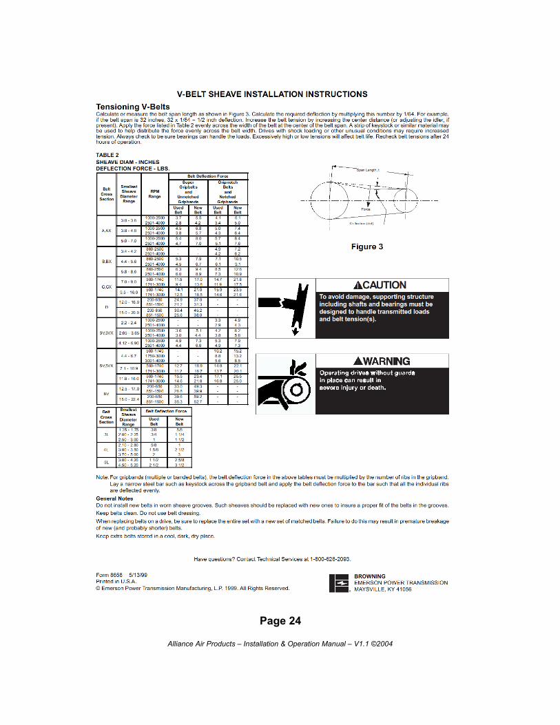
6b. Belts and Sheaves
Page 23
Alliance Air Products – Installation & Operation Manual – V1.1 ©2004
Page 24
Alliance Air Products – Installation & Operation Manual – V1.1 ©2004

6c. Coils
- Filters should be inspected on a regular basis and changed as needed. Maintaining clean filters is a cost effective way to help maintain maximum coil performance and service life.
- Periodic inspection of the coil for signs of corrosion and/or leaks is recommended. Repair and replacement of the coil and the connecting piping, valves, etc., should be performed as needed by a qualified individual(s).
- Should the coil surface need cleaning, caution should be exercised in selecting the cleaning solution as well as the cleaning equipment. Improper selection can result in damage to the coil and/or health hazards. Clean the coil from the leaving air-side so that foreign material will be washed out of the coil rather than pushed further in. Be sure to carefully read and follow the manufacturer’s recommendations before using any cleaning fluid.
- Maintain the circulated fluid free of sediment, corrosive products and biological contaminants. Periodic testing of the fluid followed by any necessary corrective measures along with maintaining adequate fluid velocities and proper filtering of the fluid will help to satisfy this goal.
- If automatic air vents are not utilized, periodic venting of the coil is recommended to remove accumulated air. Caution should be exercised to avoid injury. High pressure and/or high temperature fluids can cause serious personal injury.
- Keep condensate drain pans clean. Inspect pans on a regular basis, and clean with a commercial detergent as needed. Algaecide tablets or other products designed for this purpose may be used to prevent algae growth. Traps should also be inspected to ensure free drainage.
Page 25
Alliance Air Products – Installation & Operation Manual – V1.1 ©2004
6d. Dampers & Actuators
Dampers should be inspected semiannually. Actuators should be cycled through their entirerange to ensure that dampers can open and close fully. Blade seals, if present, should beinspected for wear and damage, and replaced if needed. Also check damper linkage. Ifpossible, disconnect actuators and manually cycle dampers, checking for binding or looselinkage or blade shafts.
Actuators normally require little or no maintenance. However, actuator hardware should bechecked periodically to ensure that attachments to shafts and linkages have not becomeloose, and that actuator is properly attached to a mounting surface.
Page 26
Alliance Air Products – Installation & Operation Manual – V1.1 ©2004