installation manual - truck accessories @ - free
TRANSCRIPT
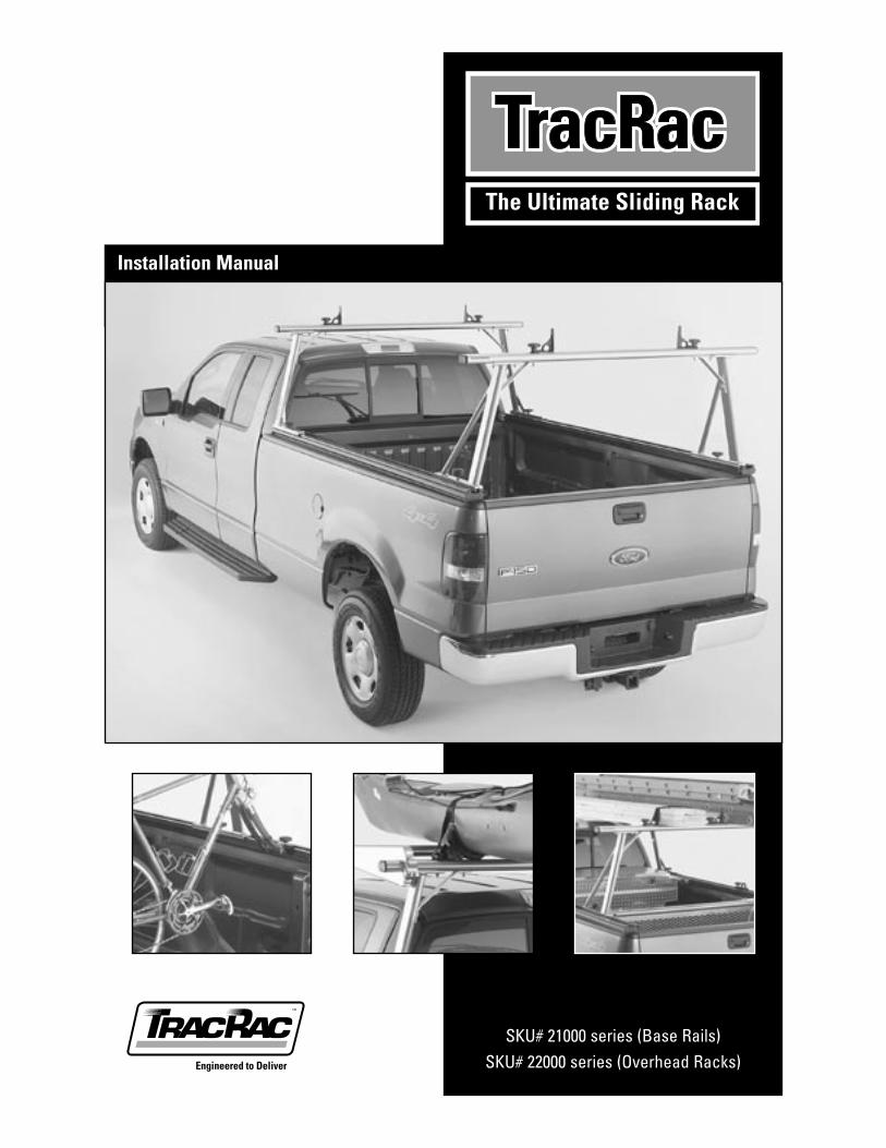
SKU# 21000 series (Base Rails)SKU# 22000 series (Overhead Racks)
Installation Manual
2 TracRac INSTRUCTION MANUAL TracRac Inc. 994 Jefferson Street, Fall River, MA 02721-4893 • 508-677-4130
Welcome to the world of TracRac!We’re delighted that you have chosen TracRac, the ultimate sliding truck rack system.
Overview:
The TracRac system consists of:
• Two triple-track base rails that fit onto the side walls of your truck bed.
• Two overhead racks that slide onto the base rails.
• 4 sliding tiedowns for use on the crossbars
Installation Procedure:
1. Verify you have received all the parts.
2. Mount the base rails onto the side walls of your truck bed.
3. Assemble and attach the overhead racks, sliding them onto the base rails.
4. Assemble and attach TracRac accessories.
The entire assembly process usually takes about 1 hour.
It’s worth taking the extra time to do it carefully, to ensure years and years of rugged performance.
If you have any questions about installation or the TracRac family of products, please call us at 1-800-501-1587.
994 Jefferson St., Fall River, MA 02721-4893 Tel: 800-501-1587, 508-677-4130 Fax: 508-677-4136
TracRac INSTRUCTION MANUAL 3 TracRac Inc. 994 Jefferson Street, Fall River, MA 02721-4893 • 508-677-4130
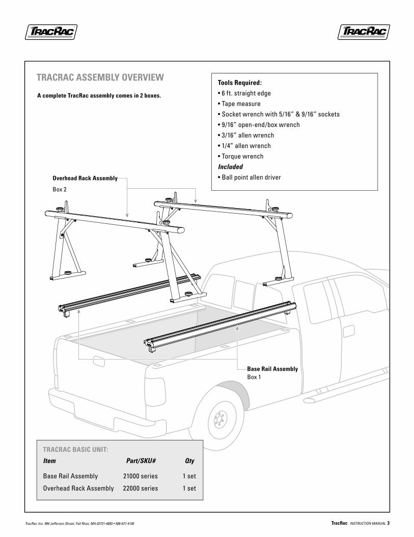
Overhead Rack Assembly
Box 2
Base Rail AssemblyBox 1
A complete TracRac assembly comes in 2 boxes.
Tools Required:
• 6 ft. straight edge
• Tape measure
• Socket wrench with 5/16” & 9/16” sockets
• 9/16” open-end/box wrench
• 3/16” allen wrench
• 1/4” allen wrench
• Torque wrench
Included
• Ball point allen driver
TRACRAC BASIC UNIT:
Item Part/SKU# Qty
Base Rail Assembly 21000 series 1 set
Overhead Rack Assembly 22000 series 1 set
TRACRAC ASSEMBLY OVERVIEW
4 TracRac INSTRUCTION MANUAL TracRac Inc. 994 Jefferson Street, Fall River, MA 02721-4893 • 508-677-4130
1
2
3
67
4
8
5
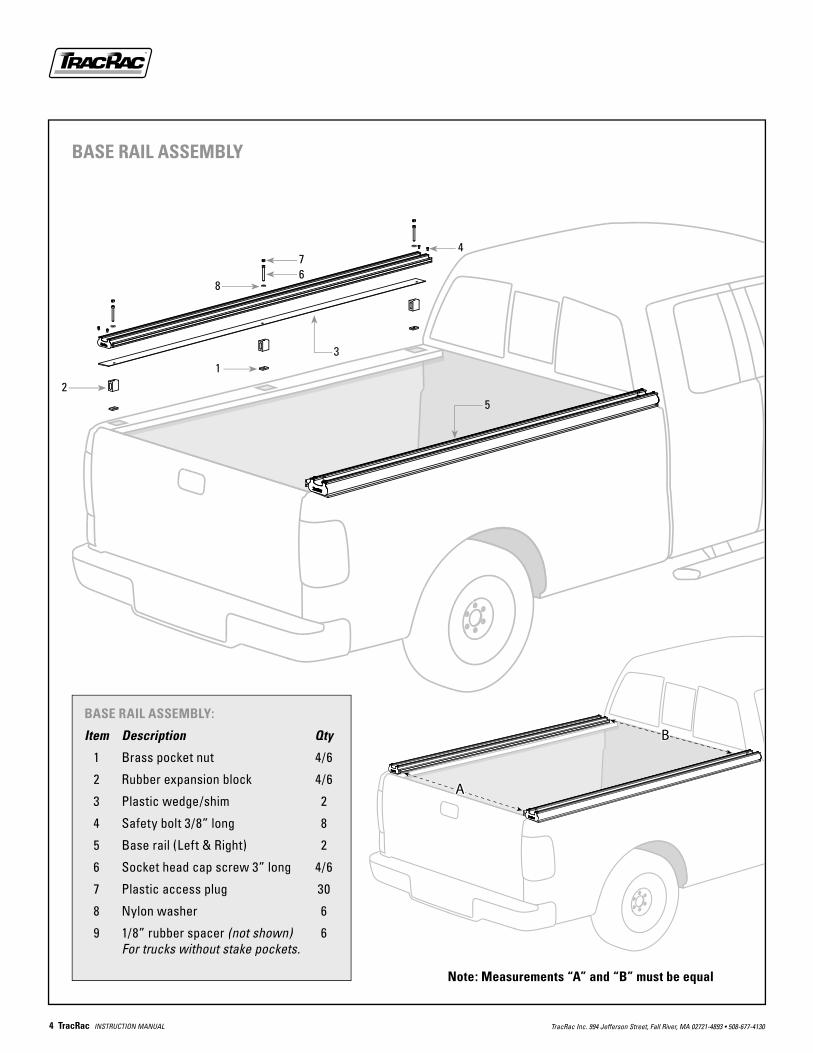
Note: Measurements “A” and “B” must be equal
BASE RAIL ASSEMBLY:
Item Description Qty
1 Brass pocket nut 4/6
2 Rubber expansion block 4/6
3 Plastic wedge/shim 2
4 Safety bolt 3/8” long 8
5 Base rail (Left & Right) 2
6 Socket head cap screw 3” long 4/6
7 Plastic access plug 30
8 Nylon washer 6
9 1/8” rubber spacer (not shown) 6 For trucks without stake pockets.
BASE RAIL ASSEMBLY
��
��
TracRac INSTRUCTION MANUAL 5 TracRac Inc. 994 Jefferson Street, Fall River, MA 02721-4893 • 508-677-4130
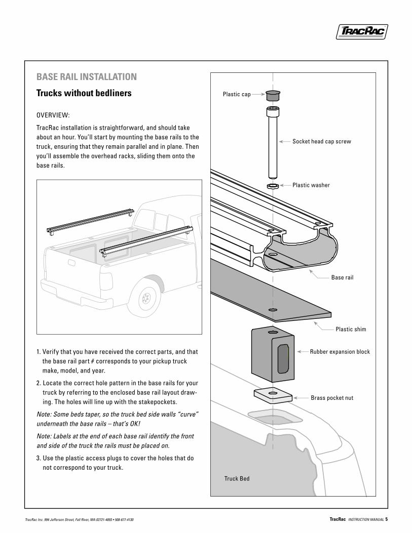
BASE RAIL INSTALLATION
Trucks without bedliners
OVERVIEW:
TracRac installation is straightforward, and should take about an hour. You’ll start by mounting the base rails to the truck, ensuring that they remain parallel and in plane. Then you’ll assemble the overhead racks, sliding them onto the base rails.
1. Verify that you have received the correct parts, and that the base rail part # corresponds to your pickup truck make, model, and year.
2. Locate the correct hole pattern in the base rails for your truck by referring to the enclosed base rail layout draw-ing. The holes will line up with the stakepockets.
Note: Some beds taper, so the truck bed side walls “curve” underneath the base rails – that’s OK!
Note: Labels at the end of each base rail identify the front and side of the truck the rails must be placed on.
3. Use the plastic access plugs to cover the holes that do not correspond to your truck.
Socket head cap screw
Plastic washer
Plastic cap
Base rail
Plastic shim
Rubber expansion block
Brass pocket nut
Truck Bed
6 TracRac INSTRUCTION MANUAL TracRac Inc. 994 Jefferson Street, Fall River, MA 02721-4893 • 508-677-4130
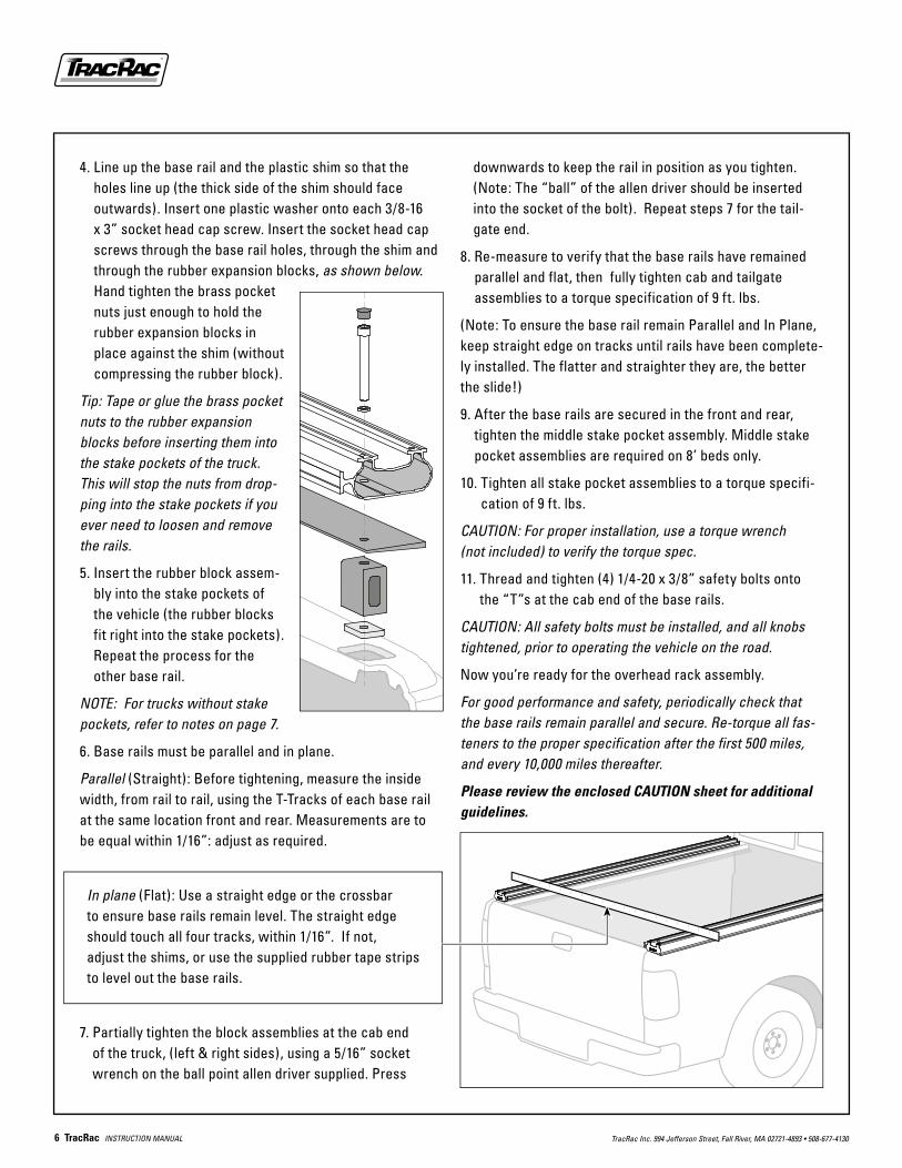
4. Line up the base rail and the plastic shim so that the holes line up (the thick side of the shim should face outwards). Insert one plastic washer onto each 3/8-16 x 3” socket head cap screw. Insert the socket head cap screws through the base rail holes, through the shim and through the rubber expansion blocks, as shown below. Hand tighten the brass pocket nuts just enough to hold the rubber expansion blocks in place against the shim (without compressing the rubber block).
Tip: Tape or glue the brass pocket nuts to the rubber expansion blocks before inserting them into the stake pockets of the truck. This will stop the nuts from drop-ping into the stake pockets if you ever need to loosen and remove the rails.
5. Insert the rubber block assem-bly into the stake pockets of the vehicle (the rubber blocks fit right into the stake pockets). Repeat the process for the other base rail.
NOTE: For trucks without stake pockets, refer to notes on page 7.
6. Base rails must be parallel and in plane.
Parallel (Straight): Before tightening, measure the inside width, from rail to rail, using the T-Tracks of each base rail at the same location front and rear. Measurements are to be equal within 1/16”: adjust as required.
In plane (Flat): Use a straight edge or the crossbar to ensure base rails remain level. The straight edge should touch all four tracks, within 1/16”. If not, adjust the shims, or use the supplied rubber tape strips to level out the base rails.
7. Partially tighten the block assemblies at the cab end of the truck, (left & right sides), using a 5/16” socket wrench on the ball point allen driver supplied. Press
downwards to keep the rail in position as you tighten. (Note: The “ball” of the allen driver should be inserted into the socket of the bolt). Repeat steps 7 for the tail-gate end.
8. Re-measure to verify that the base rails have remained parallel and flat, then fully tighten cab and tailgate assemblies to a torque specification of 9 ft. lbs.
(Note: To ensure the base rail remain Parallel and In Plane, keep straight edge on tracks until rails have been complete-ly installed. The flatter and straighter they are, the better the slide!)
9. After the base rails are secured in the front and rear, tighten the middle stake pocket assembly. Middle stake pocket assemblies are required on 8’ beds only.
10. Tighten all stake pocket assemblies to a torque specifi-cation of 9 ft. lbs.
CAUTION: For proper installation, use a torque wrench (not included) to verify the torque spec.
11. Thread and tighten (4) 1/4-20 x 3/8” safety bolts onto the “T”s at the cab end of the base rails.
CAUTION: All safety bolts must be installed, and all knobs tightened, prior to operating the vehicle on the road.
Now you’re ready for the overhead rack assembly.
For good performance and safety, periodically check that the base rails remain parallel and secure. Re-torque all fas-teners to the proper specification after the first 500 miles, and every 10,000 miles thereafter.
Please review the enclosed CAUTION sheet for additional guidelines.
TracRac INSTRUCTION MANUAL 7 TracRac Inc. 994 Jefferson Street, Fall River, MA 02721-4893 • 508-677-4130
BASE RAIL INSTALLATION:
Trucks with bedliners “Over the Rail” Make sure that the bedliner is straight and in proper posi-tion before drilling any holes!
TracRac works with over the rail bedliners – and even helps prevent the bedliner from slipping or shifting. Unless your bedliner comes with removable pocket tabs, you’ll be drill-ing holes through the bedliner to secure the base rails into the stake pockets. The base rails themselves will rest on top of the bedliner.
1. Verify that you have received the correct parts, and that the base rails correspond to your pickup truck make, model, and year.
2. Locate the correct hole pattern in the base rails for your truck by referring to the enclosed base rail layout draw-ing. Note: Labels at the end of each base rail identify the front and side of the truck the rails must be placed on.
3. Use the plastic access plugs to cover the holes that do not correspond to your truck.
4. Place the base rails on the side rails of your truck in accordance with the layout drawing. If the bedliner flange is flat and in plane, you can mount the base rails directly onto the truck without using the plastic shim.
BASE RAIL INSTALLATION:
For trucks without stake pocketsYou’ll be attaching the base rails to the side rails of the truck the old-fashioned way – by drilling 4 – 6 holes and bolting the rails in position.
C-clamp base rails onto the truck - making sure the rails are in correct position for drilling. Rails must remain paral-lel within 1/16”. Use the holes specified for your truck and mark each center.
Drill 13/32” diameter holes at each marked point and fasten in place with the 3/8-16 x 3” socket head cap screws, the plastic washers, the 1/8” thick rubber spacers, and brass pocket nuts.
Otherwise, position the shim on the top of the bedliner to ensure that the base rails remain flat and parallel (the thick side of the shim should face outwards) and/or use the supplied rubber tape as a shim to correct the angle of the base rails.
5. Starting with the front two stake pockets (closest to the cab on the left and right), locate the center of each stake pocket and drill a 3/8” hole through the bedliner. Temporarily place the 3/8-16 x 3” socket head cap screws into the correct front hole on the base rails and into bed-liner holes just drilled. Adjust the rear end of the base rails until the rails are parallel. Measure the width from rail to rail using the T-Tracks of each base rail at the same location front and rear. Measurements are to be equal within 1/16”. C-clamp the baserails in place. Now using the baserail’s rear hole as a template, drill a 3/8” diam-eter hole in the center of each rear stake pocket.
6. Unbolt the bedliner, and lift it up to gain access to the stake pockets. We suggest you place a small wooden block (2” x 4” x 4”) in between the bedliner flange and the side rail of the truck. This will permit you to access the stake pocket.
7. Slide one plastic washer onto each 3/8-16 x 3” socket head cap screw. Insert the cap screws into the holes of the base rail, through the plastic shim (again, only use shim if needed), through the bedliner, through the rubber expansion block and into brass nut.
Tip: Tape or glue the brass pocket nuts to the rubber expan-sion blocks before inserting them into the stake pock-ets of the truck. This will stop the nuts from dropping into the stake pockets if you ever need to loosen and remove the rails.
8. Hand tighten the brass pocket nuts just enough to hold the rubber expansion blocks in place against the plastic shim or bedliner (without compressing the rubber block). Remove the wooden blocks, and insert the entire assem-bly into the stake pockets.
9. Continue with steps 6 through 10 of the Base Rail Installation Instructions (page 6): Trucks without Bedliners.
8 TracRac INSTRUCTION MANUAL TracRac Inc. 994 Jefferson Street, Fall River, MA 02721-4893 • 508-677-4130
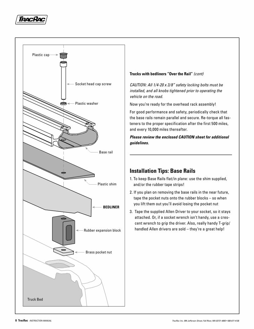
Socket head cap screw
Plastic washer
Plastic cap
Base rail
Plastic shim
Rubber expansion block
Brass pocket nut
Truck Bed
BEDLINER
Trucks with bedliners “Over the Rail” (cont)
CAUTION: All 1/4-20 x 3/8” safety locking bolts must be installed, and all knobs tightened prior to operating the vehicle on the road.
Now you’re ready for the overhead rack assembly!
For good performance and safety, periodically check that the base rails remain parallel and secure. Re-torque all fas-teners to the proper specification after the first 500 miles, and every 10,000 miles thereafter.
Please review the enclosed CAUTION sheet for additional guidelines.
Installation Tips: Base Rails1. To keep Base Rails flat/in plane: use the shim supplied,
and/or the rubber tape strips!
2. If you plan on removing the base rails in the near future, tape the pocket nuts onto the rubber blocks – so when you lift them out you’ll avoid losing the pocket nut
3. Tape the supplied Allen Driver to your socket, so it stays attached. Or, if a socket wrench isn’t handy, use a cres-cent wrench to grip the driver. Also, really handy T-grip/handled Allen drivers are sold – they’re a great help!
TracRac INSTRUCTION MANUAL 9 TracRac Inc. 994 Jefferson Street, Fall River, MA 02721-4893 • 508-677-4130
7
8
9
1012
11
10
6
5
2
1
4
3
9
12
9
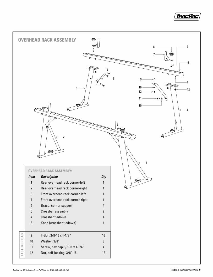
OVERHEAD RACK ASSEMBLY:
Item Description Qty
1 Rear overhead rack corner-left 1
2 Rear overhead rack corner-right 1
3 Front overhead rack corner-left 1
4 Front overhead rack corner-right 1
5 Brace, corner support 4
6 Crossbar assembly 2
7 Crossbar tiedown 4
8 Knob (crossbar tiedown) 4
9 Wear strip, crossbar 2
9 T-Bolt 3/8-16 x 1-1/8” 16
10 Washer, 3/8” 8
11 Screw, hex cap 3/8-16 x 1-1/4” 4
12 Nut, self-locking, 3/8”-16 12
FAST
ENER
BA
G
OVERHEAD RACK ASSEMBLY

10 TracRac INSTRUCTION MANUAL TracRac Inc. 994 Jefferson Street, Fall River, MA 02721-4893 • 508-677-4130
OVERHEAD RACK INSTALLATION: 1. Take the forward left and right overhead rack corner units
and slide them onto the outer tracks of the base rails. (The forward units have TracRac decals on them). Slide them up against the safety locking bolts at the cab end, insert and tighten the black plastic knobs at the base of each corner unit.
2. Take the overhead rack crossbar and orient it so that the side with the flat indentation faces down. Insert four 1 1/8” long T-bolts (head first) into the slot cut out on the underside of the crossbar. Slide two bolts into position above the saddle plates on the left and right sides.
3. Now insert the bolts through the holes in the saddle plates. Center the crossbar between the left and right corner units by adjusting the amount of crossbar that protrudes from each end of saddle plate.
Note: If you will be installing the TracRac Cantilever Extension, do not use the T-bolts on the outside of the front saddle plates to fasten the crossbar. Fasten the crossbar to the saddle plate using only the inside T-bolts.
4. Starting with the bolts on the inside left and right, tighten the self-locking nuts, leaving enough play for final adjust-ment of crossbar.
5. Re-check that the crossbar is centered between the two corner units, then tighten the outer self locking nuts completely and completely tighten the inner nuts.
6. We supply “flat bar corner braces” for extra support. To install, slide two T-bolts into the slot on the underside of the crossbar. Insert the bolts into the top holes on the flat bar brace (both left and right) and hand tighten the self locking nuts.
7. Secure the lower end of each brace to the inside of the rack corner with 3/8-16 x 1” hex head cap screws and lock washers. Go back to the crossbar T-bolts and tighten completely.
Flat indentation
Raised edge
Saddle plate
Crossbar Tiedown
Knob
T-Bolt
WasherNut
Hex Head Cap Screw
Washer
Corner Unit
Saddle Plate
T-Bolt
Dimple Side
Flat bar corner brace
Crossbar
Knob
Crossbar
CAUTION: All fasteners in overhead rack assembly must be tightened
to a torque specification of (20-25 ft-lbs).
TracRac INSTRUCTION MANUAL 11 TracRac Inc. 994 Jefferson Street, Fall River, MA 02721-4893 • 508-677-4130
8. Repeat steps 1 through 7 for the rear corner units. Mount the rear rack onto the inner tracks for maximum capacity and strength.
CAUTION: All fasteners in overhead rack assembly must be tightened to a torque specification of (20-25 ft-lbs).
9. Slide the crossbar tiedowns onto the overhead rack crossbars. (Note: Loosen knob, then insert the T-bolt into the groove first).
10. If no other accessories are to be installed, insert the remaining four 1/4-20 x 3/8” safety locking bolts into the threaded holes at the tailgate end of the base rails.
Congratulations – Racks are now installed and can slide to any position along the bed of the truck.
CAUTION: All 1/4-20 x 3/8” safety locking bolts must be installed, and all knobs tightened prior to operating the vehicle on the road.
TracRac is capable of carrying a maximum of 1000 lbs., evenly distributed when configured with the rear rack mounted on the inner track.
For good performance and safety, periodically check that the base rails remain parallel and secure. Re-torque all fas-teners to the proper specification after the first 500 miles, and every 10,000 miles thereafter. Lubricate the threaded portion of all knobs every 2000 miles.
Carrying high loads over rough roads with excess speed may damage the system. Exercise good judgment at all times.
Please review the enclosed CAUTION sheet for additional guidelines.
12 TracRac INSTRUCTION MANUAL TracRac Inc. 994 Jefferson Street, Fall River, MA 02721-4893 • 508-677-4130
TIPS FOR CARE AND MAINTENANCE
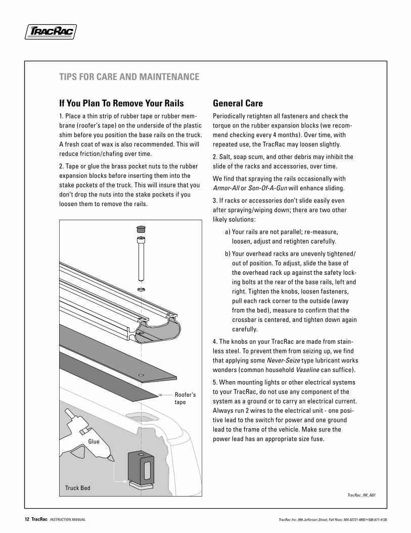
If You Plan To Remove Your Rails1. Place a thin strip of rubber tape or rubber mem-brane (roofer’s tape) on the underside of the plastic shim before you position the base rails on the truck. A fresh coat of wax is also recommended. This will reduce friction/chafing over time.
2. Tape or glue the brass pocket nuts to the rubber expansion blocks before inserting them into the stake pockets of the truck. This will insure that you don’t drop the nuts into the stake pockets if you loosen them to remove the rails.
General CarePeriodically retighten all fasteners and check the torque on the rubber expansion blocks (we recom-mend checking every 4 months). Over time, with repeated use, the TracRac may loosen slightly.
2. Salt, soap scum, and other debris may inhibit the slide of the racks and accessories, over time.
We find that spraying the rails occasionally with Armor-All or Son-Of-A-Gun will enhance sliding.
3. If racks or accessories don’t slide easily even after spraying/wiping down; there are two other likely solutions:
a) Your rails are not parallel; re-measure, loosen, adjust and retighten carefully.
b) Your overhead racks are unevenly tightened/out of position. To adjust, slide the base of the overhead rack up against the safety lock-ing bolts at the rear of the base rails, left and right. Tighten the knobs, loosen fasteners, pull each rack corner to the outside (away from the bed), measure to confirm that the crossbar is centered, and tighten down again carefully.
4. The knobs on your TracRac are made from stain-less steel. To prevent them from seizing up, we find that applying some Never-Seize type lubricant works wonders (common household Vaseline can suffice).
5. When mounting lights or other electrical systems to your TracRac, do not use any component of the system as a ground or to carry an electrical current. Always run 2 wires to the electrical unit - one posi-tive lead to the switch for power and one ground lead to the frame of the vehicle. Make sure the power lead has an appropriate size fuse.
Truck BedTracRac_IM_A01
Roofer’s tape
Glue