installation manual ring-master system cb901
TRANSCRIPT

RING-MASTER INSTALLATION MANUAL CB901-1
1Ring-Master
F A S T A C C E S S C O M M U N I C A T I O N
Installation ManualRing-Master System CB901
Ring-Master Communication &
Security Systems
Ring-Master
from Alpha Communications

2
CB901-1 RING-MASTER INSTALLATION MANUAL
Ring-Master
No text on this page

RING-MASTER INSTALLATION MANUAL CB901-1
3
CHAPTER 1. CB901-1
Paragraph 1. Introduction Page 51.1. General System Description Page 51.2. Central layout Page 9
Paragraph 2. Stations Page 11
Paragraph 3. Installation Page 133.1. Installation planning Page 133.2 Central location Page 133.3. Cabling requirements Page 143.4. Installation of central exchange Page 153.5. Mounting the cardrack backplate Page 153.6. Cable termination in station sockets Page 163.7. Cable termination in central cardrack Page 163.8. Installation of the cardrack Page 173.9. Power unit specs., central and station power needs, Page 17 and connection of power units3.10 Plugging in printed circuit boards Page 193.11 Installation of Programme Distribution card DP977 Page 193.12 Power on and system check Page 213.13 Adjustments Page 723.14 Installing EMC approved cardracks DP991
and DP992 Page 233.15. Display Master Station AA960, connection of
external functions Page 30
Paragraph 4. Programming Page 31
Paragraph 5 Final Checkout and Commissioning Page 33
Paragraph 6. Technical Specifications Page 43
Ring-Master
WWT-167E Published July 1998.
.
STENTO ASA and its subsidiaries assume no responsibility for any errors that may appear in itsdocumentation, or damages arising from the information in it. No information in this publication should beregarded as a warranty made by STENTO ASA.STENTO ASA reserves the right to make changes in specifications of the products detailed in thishandbook as well as the contents of this handbook at any time and without notice. This is consistent with ourpolicy of continuous product analysis and improvement.Product names mentioned in this publication may be trademarks. They are used only for identification.

4
CB901-1 RING-MASTER INSTALLATION MANUAL
Ring-Master
No text on this page

RING-MASTER INSTALLATION MANUAL CB901-1
5Ring-Master
1.1. GENERAL SYSTEM DESCRIPTION
1. INTRODUCTION
Fig. 1.1. System CB901, Layout.
Ring-Master system CB 901 is an all-to-all direct speech system, controlled by afully electronic central exchange. Similar to a mini-computer, all its functions aremicroprocessor controlled. This enables the customer to select from a wide range ofprogrammable features designed to achieve flexibility and optimal efficiency in internalcommunication.
A built-in Lithium battery will secure all programmed information up to 10 yearswhen power to system is switched off.
The modular structure of the central permits easy expansion, station by station,from 2 up to a capacity of 7.170 subscribers and beyond. Moreover, a wide variety ofstation types, matching the needs of almost any user, whether institutional, industial orcommercial applications, increases the flexibility of the system.
The unique cabling concept provides the advantages of both centralized anddecentralized cabling arrangements. Each station requires one single pair for diallingand conversation. Power can either be individual to each station or, using a singlereference pair, remote groups of stations can be supplied from local mains power units.The cabling between master unit and each slave is ordinary telephone wires or opticalfibre.
FAIL-SAFE POWERSUPPLY
STATION CAPACITY2 - 2.170
SIMPLIFIED CABLING
TRANSMITTER FOR PAGING SYSTEM
ALARM CONTACT IN VARIOUS LOCATIONS(DRY CONTACTS)
RADIO PAGING
INTERFACE
PRINTER FOR LOGGING OFALARM CALLS
REGISTRATION OF ALARM CALLS. DATABASE
VISICALL AE111 FOR ALARM REGISTRATION(FOR ALTERNATIVE CONTROL ROOM)
TRANSMITTER FOR RADIO NETWORK
PORTABLE RADIO HANDSET W/TEXT
104
1 2 3
4 5 6
7 8 9
* 0 # PAGING RECEIVERW/TEXT
1 2 3
4 5 6
7 8 9
T 0 X
AA916DESK/WALL
MASTER
SUPERVISOR CONTROL ROOM
RING-MASTER EXCHANGE ROOM
LINE TERMINALS
AA912INDUSTRIAL
MASTER
AB931PRISON
STATION
AB933VANDAL PROOF
STATION
AB933ADOOR
STATION
CCTVCAMERAS
VARIOUSALARM/CALL
BUTTONS
AA961INDUSTRIAL
DISPLAY MASTER
RC104BED CALLSTATION
CLOSED RADIO
NETWORK INTERFACE
GATE 12
1 2 3
4 5 6
7 8 9
T 0 X
P M
CCTV MONITOR
AA960DISPLAYSTATION
CCTVSWITCH
BC934SPEAKER
UNIT
4 wires toeach station
PUBLIC TELEPHONE NETWORK
CB901
F
1 2 3
4 5 6
7 8 9
0 #
M T X
1 2 3
AA903FLUSH
MASTER
AB931ADOOR
STATION
1 2 3
4 5 6
7 8 9
T 0 X
AA906HEAVY
INDUSTRIALMASTER
AA905INDUSTRIAL
MASTER
1 23 4579T
680X

6
CB901-1 RING-MASTER INSTALLATION MANUAL
Ring-MasterFig. 1.2. CB901, System Configuration
SINGLE-STAGE SYSTEM CB 901-1
SUBSCR. CARDRACK DP980160 SUBSCRIBERS
BASIC CARDRACK DP979
80 SUBSCRIBERS
POWER
SUBSCR. CARDRACK DP980160 SUBSCRIBERS
BASIC CARDRACK DP979
80 SUBSCRIBERS
POWER
SUBSCR. CARDRACK DP980160 SUBSCRIBERS
BASIC CARDRACK DP979
80 SUBSCRIBERS
POWER
SUBSCR. CARDRACK DP980159 SUBSCRIBERS
BASIC CARDRACK DP979
80 SUBSCRIBERS
POWER
SUBSCR. CARDRACK DP980159 SUBSCRIBERS
BASIC CARDRACK DP979
80 SUBSCRIBERS
POWER
SUBSCR. CARDRACK DP980159 SUBSCRIBERS
BASIC CARDRACK DP979
80 SUBSCRIBERS
POWER
SUBSCR. CARDRACK DP980159 SUBSCRIBERS
BASIC CARDRACK DP979
80 SUBSCRIBERS
POWER
SUBSCR. CARDRACK DP980159 SUBSCRIBERS
BASIC CARDRACK DP979
80 SUBSCRIBERS
POWER
SUBSCR. CARDRACK DP980159 SUBSCRIBERS
BASIC CARDRACK DP979
80 SUBSCRIBERS
POWER
SUBSCR. CARDRACK DP980
159 SUBSCRIBERS
BASIC CARDRACK DP979
80 SUBSCRIBERS
POWER
DIGITAL TRANSMISSIIN; 2 PAIR TWISTED CABLE - MAX 1.5 KM
DOUBLE-STAGE SYSTEM CB 901-2
TRIPLE-STAGE SYSTEM CB 901-3
INTERCONNECTION TO EACH STAGE BY2 PAIR TELEPHONE WIREOR BY OPTICAL FIBRE
TO A MAXIMUM OF 30 STAGES
MULTI-STAGE SYSTEM CB 901-M (UP TO 30)
TRUNKINTERFACE
LAYOUT BASED ON CPU CARD NFE 1683,
REVISION TX 3.3 OR LATER.
NETWORKINTERFACE
NETWORKINTERFACE
NETWORKINTERFACE
NETWORKINTERFACE
TRUNKINTERFACE
TRUNKINTERFACE
TRUNKINTERFACE
DIGITAL NETWORK CONTROLLER
NETWORK DATA SWITCH NETWORK PROCESSOR
DIGITAL TRANSMISSION; 2 PAIR FIBRE OPTICAL CABLE - MAX 7.2 KMANALOGUE TRANSMISSION:18 PAIR INSTALLATION CABLE - MAX 1.5 KM
DIGITAL TRANSMISSIIN; 2 PAIR TWISTED CABLE - MAX 1.5 KM BETWEEN EACH STAGEDIGITAL TRANSMISSION; 2 PAIR FIBRE OPTICAL CABLE - MAX 7.2 KMBETWEEN EACH STAGEANALOGUE TRANSMISSION:18 PAIR INSTALLATION CABLE - MAX 1.5 KM BETWEEN EACH STAGE
DIGITAL TRANSMISSIIN; 2 PAIR TWISTED CABLE - MAX 1.5 KM BETWEEN DNC AND EACH STAGEDIGITAL TRANSMISSION; 2 PAIR FIBRE OPTICAL CABLE - MAX 7.2 KMBETWEEN DNC AND EACH STAGE

RING-MASTER INSTALLATION MANUAL CB901-1
7Ring-Master
The central unit is compact. A standard basic cardrack equipped for 96subscribers measures only 256 mm x 570 mm x 271 mm (10.1" x 22.4" x 10.9"). Silentin operation, once fitted with its cover, the central can operate inconspicuously in almostany location.
The Ring-Master CB 901 system is divided into four categories based on thenumber capacity:
Single-Stage System CB 901-1 - up to maximum 240 subscribers
Double-Stage System CB 901-2 - above 240 and up to 480 subscribers
Triple-Stage System CB 901-3 - above 480 and up to 717 subscribers
Multi- Stage System CB 901-M - above 717 up to maximum 7.170 subscribers
In a single-Stage system, the central unit consists of a Basic Cardrack DP 979containing the Basic Cardset and Subscriber Cards, totalling 96 subscribers. If thenumber requirements exceed this, an additional Subscriber Cardrack DP 980 isnecessary, giving a maximum capacity of 240 subscribers in a single-stage system.
In a Double-Stage system CB 901-2, two Single Stage systems CB 901-1 areinterconnected by:A. Analog Transmission on Multi-pair cable;
a 18-pair installation cable. The system is equipped for 8 interlinks betweenthe stages. Maximum distance between the stages is 1.5 KM. Each stagecan have 240 subscribers, giving a maximum capacity of 480 in a Double-Stage system.
B. Digital Transmission on one pair fibre optical cable or two pair twisted datacable.The system is equipped for 8 interlinks between the stages. Maximumdistance between the stages is 7.2 KM. Each stage can have 240subscribers, giving a maximum capacity of 480 in a Double-Stage system.
The Triple-Stage system CB 901-3 configuration consists of three Single Stagesystems CB 901-1 interconnected by:
A. Analog Transmission on Multi-pair cable:a 18-pair installation cable in a triangle configuration. The system isequipped for 8 interlinks between each stage. Maximum distance betweenthe stages is 1.5 KM. Each stage can have 239 subscribers, giving amaximum capacity of 717 in a Triple-Stage system.
B. Digital Transmission on one pair fibre optical cable or two pair twisted datacable in a triangle configuration. The system is equipped for 8 interlinksbetween each stage. Maximum distance between the stages is 7.2 KM.Each stage can have 239 subscribers, giving a maximum capacity of 717 ina Triple-Stage system.
The Multi-Stage system CB 901-M configuration consists of one control unitcalled DNC (Digital Network Controller) and up to 30 slave stages. The DNC unit has nosubscriber connection itself, all slave stages are wired to this unit and it handles alltraffic between them. For interconnection, fibre optic or standard telephone cable (2 pair)can be used. Each slave stage contains maximum 239 call numbers - which gives atotal capacity of 7.170 subscribers in a system. A Multi-Stage system CB 901-Msystem gives 8 interlinks (audio channels) between the DNC unit and each node slavestage.
COMPACT SIZE
SYSTEMCONFIGURATIONS

8
CB901-1 RING-MASTER INSTALLATION MANUAL
Ring-Master
Each slave-stage of 240 numbers is equipped with 15 internal links. Each DigitalNetwork Controller (DNC) is equipped with 1024 internal links. Between each slavestage and the DNC unit 8 interlinks are available.
LINK CAPACITY
Fig. 1.3. Link Capacity
SUBSCR. CARDRACK DP980159 SUBSCRIBERS
BASIC CARDRACK DP97980 SUBSCRIBERS
POWER
SUBSCR. CARDRACK DP980159 SUBSCRIBERS
BASIC CARDRACK DP97980 SUBSCRIBERS
POWER
SUBSCR. CARDRACK DP980159 SUBSCRIBERS
BASIC CARDRACK DP97980 SUBSCRIBERS
POWER
SUBSCR. CARDRACK DP980159 SUBSCRIBERS
BASIC CARDRACK DP97980 SUBSCRIBERS
POWER
DIGITAL NETWORK CONTROLLER
INTERCONNECTION TO EACH STAGE BY2 PAIR TELEPHONE CABLEOR BY OPTICAL FIBRE
TO A MAXIMUM OF 30 STAGES
SYSTEM LINK CAPACITY
15 INTERNAL LINKS 15 INTERNAL LINKS 15 INTERNAL LINKS 15 INTERNAL LINKS
8 INTERLINKS BETWEEN EACH STAGE AND DNC UNIT
INTERNAL CB 901/INTERLINKS/INTERNAL DNC
1024 INTERNAL LINKS
8 LINKS 8 LINKS 8 LINKS 8 LINKS 8 LINKS

RING-MASTER INSTALLATION MANUAL CB901-1
9Ring-Master
THE CB 901-1 SYSTEM CONTAINS THE FOLLOWING PRINTED CIRCUIT CARDS:
19 Processor Card NFE 168318 Timing Control Card NFE 160617 Switch Control Card NFE 151916 Audio Control Card NFE 1607
15-14 Link Control Cards - 2 pcs. - 15 links NFE 15211 Power card NFE 1528
2-13 Subscriber Cards (8 subscribers per card) NFE 1625 21-40 Subscriber Cards (8 subscribers per card) NFE 1625 (10) Programme Distribution Card NFE 1626, if required).
The number of subscribers in a CB 901-1 system may be expanded in steps of 8,plugging in subscriber cards.
The basic cardrack 10 subscriber cards = 80 subscribersThe subscriber cardrack 20 subscriber cards = 160 subscribersGiving a maximum capacity of 239 subscribers, each with access to the 15 links.
Fig. 1.4. CB901-1, PCB Layout
1.2. CENTRAL LAYOUT.
19 18 17 16 15 14 2
BASIC CARDRACK DP 979
SUBSCRIBER CARDRACK DP 980
13 12 11 10 9 8 7 6 5 4 320 1
39 38 37 36 35 34 2233 32 31 30 29 28 27 26 25 24 2340 21

10
CB901-1 RING-MASTER INSTALLATION MANUAL
Ring-Master
Each stage in the central unit consists of a basic cardrack for the common basiccardset, and according to the number capacity, an additional subscriber cardrack.
All cards in a CB 901 system are of plug-in type, interwired via the motherboard in eachcardrack.
The common basic cardset comprises 7 different types of printed circuit cards, whichare briefly described in the following:This card contains the microprocessor (MC 68000 series), its programme and memory.The 512K bytes programme, which controls all computer operations is located in 4PROMs (Programmable Read Only Memories). The operating system is MTOS and theprogramme is written in high level language C.
It contains the main oscillator (10.7 MHz) and provides all timing signals in the centralunit. In this way the system is synchronized all the way through, which minimizes noisegeneration on the audio links.
This card sets up/disconnects links, directed by the processor. It handles the PAM(Pulse Amplitude Modulation) sampling control for all links. There are 32 time-slots inthe sytem. One time-slot is allocated by the subscriber scanner and one for the tonereceiver, leaving 30 time-slots for audio connections. This means that there is room for15 simultaneous audio links.
The duplex voice control circuits are located on this card, together with the reciever andtone transmitter. The processor fully controls the tone receiver/transmitter.
The duplex control circuit operates individually for each time-slot, which is much fasterthan the processor can manage. Therefore, a separate control system is included onthis card.
It connects the audio signals between the subscribers. Each card handles 8 links andthere are always 2 link cards in the central unit.
It contains a switching power supply, synchronized with the main oscillator to minimizenoise. Input to the card is 25 - 28V DC.
It terminates the lines for 8 subscribers, and is the interface card between the stationsand the central unit. The card splits up the audio/signalling information to/from thesubscribers. All subscriber cards are identical.
In a fully equipped CB 901 system there is room for 2 more card types, which are:
It interfaces the intercom system to an external programme source and allows thesubscribers to activate and connect programme- (music) and alarm channels.Implementing this feature to the system will reduce the total number of subscribers by 8per stage.
The distance between Digital Network Interface Card (installed in the Basic Cardrack ina stage) is up to 7.2 km. For analog configuration the Analog Interlink Card NFE1545 isused. The distance between each stage is 1.5 km. Both type of cards contain 8 audiolinks used between stages in a Double-Stage System CB 901-2 (one card in eachstage) and Triple-Stage System CB 903 (two cards in each stage).
Two different types of CB901 cardrack configurations are available from Ring Master:
PROCESSOR CARD
TIMING CONTROLCARD
SWITCH CONTROLCARD
AUDIO CONTROLCARD
LINK CARD
POWER CARD
SUBSCRIBER CARD
PROGRAMMEDISTRIBUTIONCONTROL CARD
ANALOG INTERLINKCARD/DIGITAL NET-WORK INTERFACE(FOR EXPANSIONTO CB 901-2, CB 901-3AND CB901-MSYSTEMS).

RING-MASTER INSTALLATION MANUAL CB901-1
11Ring-Master
2. STATIONS
Fig. 1.5. Display Station AA960
The stations are basically divided into two categories; Master Stations andSub Stations.Master Stations - able to make calls or to receive calls from any other call number.Sub Stations - for receiving calls only, from any master station. Some substationshave keypad with limited call access (station with auto-dialling and stations with directaccess feature).
A variety of models are available. These include two Master Stations designed fordesk or wall-mounting;
- AA960, station with 8-character alphanumeric display- AA904 station without display, but utilizing the same standard features as the
AA960 model,a flush-mounted unit AA903, an industrial heavy-duty station AA906, one light indus-trial station AA905, ex-proof station AA908 and substations for desktop or wall-mounted use, and remote microphone units and door substations.
Each master station is equipped with a keyboard with full international standards,simple push-button dialling process places all the features at the user’s finger tips.
Making a call, the user presses the button corresponding to the first digit of thedesired call number. Dial access is virtually instantaneous since all station positionsare scanned continuously. On receiving a steady dialling tone, the user continuesdialling.
Call connection is indicated in both the initiating and the receiving station by awarning tone and a station lamp which remains lit until the call is cancelled by eitherparty pressing X. Should the link be busy, the caller receives an intermittent tone. Acontinuous warbling tone indicates, that a station is placed in privacy, wishing toremain undisturbed.
MODELS
OPERATING THESTATION
Excellent sound reproduction.
Multi-colour LED for indications. Red duringconversation.
8 characters alpha-numeric display.- station's call number- station's ID text- time (12 or 24 hrs. indication)
Scroll keys for the display
Function key, F
Key to activate confidential mode.
Volume control keys, volume up/down
Standard international telephone keypad
T-to-talk" optional manual control of calls.
Microphone mut key
"X-to-cancel" key.
Sensitive microphone.

12
CB901-1 RING-MASTER INSTALLATION MANUAL
Ring-Master
The following station models are available, please see the GUIDE TO RING-MASTERSYSTEM RM5000 or TECHNICAL MANUAL, OPTIONAL EQUIPMENT for more details:
AA903 Flush-mounted Master StationAA905B Light Industrial Master Station, SurfaceAA905C Light Industrial Master Station, FlushAA906 Heavy-Duty Industrial Master StationAA911-F Master Station w/polyester film front, FlushAA912 Light Industrial Master Station, SurfaceAA912-F Light Industrial Master Station, FlushAA916 Desk/Wall Master Station without displayAA960 Desk/Wall Master Station with displayAA961 Industrial Master Station with display, SurfaceAA961-F Industrial Master Station with display, FlushAB923 Substation w/3 call buttons, SurfaceAB923-F Substation w/3 call buttons, FlushAB931 Vandal-proof station w/1 call button, SurfaceAB931-F Vandal-proof station w/1 call button, FlushAB933 Vandal-proof station w/3 call button, SurfaceAB933-F Vandal-proof station w/3 call button, FlushAB931A Door station w/1 call button, SurfaceAB931A-FDoor proof station w/1 call button, FlushAB933A Door station w/3 call button, SurfaceAB933A-FDoor station w/3 call button, FlushAE111 VISICALL, Direct Dialling UnitAF103 Explosion-proof Master Station
RING-MASTER INSTALLATION MANUAL CB901-1
13Ring-Master
3. INSTALLATION- Standard Cardrack configuration, Basic Cardrack DP978 and Subs. Cardrack DP980- EMC Approved Cardrack configuration, Basic Cardrack DP991 and Subscriber
Cardrack DP992.The units are CE marked and complies with these standards in the EMC Directive:EMISSION; EN-50081-1 (EN 55022/CISPR 22, Class b), andIMMUNITY; EN-50082-1, (IEC 801-2, IEC 801-3 and IEC 801-4.The 19" card cassetts used in the EMC approved cardracks are produced byELMA. The Motherboard and all Subscriber- and Interface Cards are identical
to those used in the standard configuration.Please see paragraph 1.14: Installing EMC approved cardracks DP991 and DP992 forinstallation details.
Proper planning minimizes the time required and costs incurred during an installation. Inthe long term, maintenance, changes and expansion can be accomplished efficientlywhen planned for prior to the initial installation. This results in customer satisfaction andgoodwill through a minimum disruption of their business activities. Ultimately, customersatisfaction results in additional sales.Each customer’s facility is different, and requires a tailored approach to ensure that thejob runs smoothly. Each facility will have its own combination of circumstances whichmust be addressed. Table below summarizes the major stages of a typical intercominstallation. The sequence in which the stages are accomplished, or the workaccomplished in each stage itself, can be modified to reflect the particularcircumstances of each intallation. However, the general approach should include theinstallation stages listed below:
STEP INSTALLATION
1. Site survey and data collection.2. Plan major equipment layout. (Central, system power supply, and
position of the variuos stations, speakers, etc.)3. Plan cable routing.4. Preparation and preassembly of central and power supply at shop
facility.5. Site work:
a. Running of station cablesb. Equipment mounting (central, power supply, etc.)c. Station and speaker installationd. System programming and adjustment
6. System checkout and commissioning7. Customer introduction and training.
A summary of the environmental factors affecting the Ring-Master CB901 system ispresented in the listing below. These factors must be considered when developing adetailed system plan.Site preparation is dependent upon the customer’s facilities. In many cases, there maybe only one location where the central and power supply (or transformer) can bemounted. However, when several locations are possible, the advantages anddisadvantages of each location should be considered. Consider each of the followingfactors:
3.1. INSTALLATION PLANNING
3.2. CENTRAL LOCATION

14
CB901-1 RING-MASTER INSTALLATION MANUAL
Ring-Master
A. The central and power supply must be wall mounted.
B. Location of the majority of stations, locate the central strategically, so that you can minimize the length of cable runs.
C. Location of existing telephone ducts or conduit.
D. The AC line should be dedicated exclusively to the system. If the line is equipped with a circuit breaker at the service entrance panel, the circuit breaker switch should be labeled «DO NOT TURN OFF».
E. The equipment should be installed in an area that has adequate ventilation. A temperature range of 0oC (32oF) to 25oC (77oF) and humidity range of 30% to 90% relative must be maintained.
F. Appropriate lighting conditions and adequate working space should be provided for future service calls.
G. Consideration must be given to those conditions that may cause damage to the equipment. For example, dust or vapor from flammable or corrosive solvent may cause damage. The installation site should not be located in an area likely to be flooded or likely to be damaged by moving objects nearby.
H. The central should NOT be installed in an area near electrical noise including equipment, i.e., heavy motors, welders, dimmers, radio transmitters etc.
I. The power supply (or transformer) must be mounted ABOVE the central. This is to prevent overheating the central.
Each station is connected to the central by 4 leads (in two twisted pairs). See Fi1. 3.8.
Leads No. 1 and No. 2. Audio and signalling.Individual leads i.e., a separate twisted pair is required for each station. Galvanicallyconnected to 3M subscriber terminals of flat cables BF 925 in the central, these pairscarry tone-signalling (CCITT norm.) for dialling, audio transmission and DC controlsignals for stations.
The maximum loop-resistance of this pair is 240 ohm corresponding to approx. 2kmcable-length from station to central, using normal telephone cabling with 0.6 mm diam.wiring. If the actual distance is more than 2 km. (loop resistance more than 240 ohm)doubling this audio pair (or using heavier cable) can cause incorrect dialing transmiss-ion, since the capacitance in the cable is also increased. Doubling is not recommended.If cable to a station passes close to radio aerials or other interference sources, the leadsto the actual station should be shielded.
Leads No. 3 and No. 4. Station Operating Voltage.These leads carry operating voltage to the stations. The maximum/ minimum stationvoltage for proper operation is 28,5 - 21V. This allows a loop resistance between eachstation and power supply (centralized or local) of 40 ohm, giving a distance of 350meters on 0.6 mm copper wire and 600 m on 0.8 mm. (based on power supply output of27V DC).
NON-STRUCTURALCONSIDERATIONS:
3.3. CABLING REQUIREMENTS

RING-MASTER INSTALLATION MANUAL CB901-1
15Ring-Master
The wire dimensions for stations located further from the central must be increasedaccordingly. However, independant local DC power supplies can be used for distantstations. No referance wiring between local and central power supplies is required.
Important Note : If a number of stations are powered from a common/parallel DC powerpair, voltage fluctuations can result in incidental crosstalk. Therefore it is essential that aseparate power pair is always used for each station.
Each basic cardrack and subscriber cardrack consists of two main parts: a metalbackplate and a front cardrack (which secures to the backplate with 2 screws) thatswivels outward, giving access behind the motherboard during maintenance.
Check for signs of physical damage when unpacking the central. In particular check thelong contact-pins on the rear of the motherboards NFE 1522, NFE 1523A and NFE1524A for possible distortion that may cause short-circuiting.
NOTE: To facilitate station cable connections and installation of cards, it isrecommended that the cardrack is unscrewed and separated from the backplate duringthe initial installation procedures.
Four holes in the backplate are provided for mounting on a wall or 19" rack. The positionof the cardracks should allow for easy access of incoming station cables.
Check that the following components are mounted on the backplate:
a. Two brackets for station connection terminals.
b. One bracket, in which a printed circuit card is mounted. This board provides fuseholders (1.6 amp), connecting lugs for station power, and screw terminals for voltagefrom external power supply.
Now mount the backplate, as follows:
a. Drill holes corresponding to the backplate in the wall.
b. Mount the backplate (see note).
NOTE: The four screws required for wall mounting the central unit are not provided. Becertain that the screws used can support the central unit.
When using two cardracks for a central unit, two 20-pair flat cables (NMF6002) issupplied with DP 980 Cardrack to connect the two units together. The cables have afixed length, thus limiting the distance between the cardracks to approximately 10-12cm (4-4,5 inches). (See Fig. 1.6, 1.7). The top pin of Cable no. 1 in each pin row will notbe connected.The backplate is now ready for station wiring.
Station type: Master Station AA960 w/display - modular 8 pin RJ45 socket.Leads No. 1 and No. 2 - Audio Signalling Leads
Lead No. 1 to be connected to pin No. 5 in the RJ45 station socket.Lead No. 2 to be connected to pin No. 4 in the RJ45 station socket.
3.4. INSTALLATION OF CENTRAL EXCHANGE.
3.5. MOUNTING THE CARDRACK BACKPLATE.
3.6. CABLE TERMINATION IN STATION SOCKETS (See Fig. 1.8.)

16
CB901-1 RING-MASTER INSTALLATION MANUAL
Ring-Master
Leads No. 3 and No. 4 - Station Operation Voltage.Lead No. 3 is positive and must be connected to pin No 3 in the RJ45 socket.Lead No. 4 is negative and must be connected to pin No. 6 in the RJ45 socket.
Station type: All station types (Sub- and Master) using Hirschmann 6 pin socketLeads No. 1 and No. 2 - Audio Signalling Leads
Lead No. 1 to be connected to pin No. 1 in the Hirschmann socket.Lead No. 2 to be connected to pin No. 5 in the Hirschmann socket.
Leads No. 3 and No. 4 - Station Operation Voltage.Lead No. 3 is positive and must be connected to pin No 3 in the socket.Lead No. 4 is negative and must be connected to pin No. 6 in the socket.
NOTE: Always use a separate power pair for each station to the DC power source, toavoid crosstalk.
If an extra loudspeaker is required in parallel to the station’s speaker, connect to pins1 and 2 on the RJ45 wall socket or to pin 5 and 6 on the Hirschmann wall socket.Note,min. impedance 16 ohm.
NOTE: It is stressed that the station’s built-in output amplifier shall not be overloaded.Therefore, when an extra speaker is used, the station’s volume control shall not be sethigher than half-way. If extra power is needed, an extra booster amplifier (e.g. FC 420/10W with independant power supply) must be inserted between pins 1 and 2 on RJ45(or pin 5 and 6 on the Hirschmann plug) and the one or more parallel speakers.
Connection of stations’ speech/signalling pair (leads 1 and 2).Connect to the 3M terminal blocks of the flat cable straps BF 925. The 3M blocks areclipped vertically into brackets on the central’s backplate and the other ends of the flatcables are plugged into corresponding vertical pin-rows on the rear of the central’smotherboard. See Figure 3.9.The 3M blocks are fitted with «knife-type» terminals requiring a special connecting tool3M/4055 (RM cat. no QHF 1027).
To start the connections, the first 3M block will be clipped into the top/left bracketposition on the backplate. This will correspond to the positions for stations withhex.pos.nos. 00-07. Each 3M block has a vertical row of 20 «knife-terminals». The first 4(or upper) terminals are not to be used. Connecting the 1/2 leads for the first of the 8stations on the 3M block, plug into terminals 5 and 6 for station no. 00, the second to 7and 8 for station 01, and so on up to no. 07.
Removing the mounting bracket and plugging in the 3M block of BF 925 to the top leftbackplate position, the next 3M block will be located at the lower-left backplate position,corresponding to the wiring positions for stations with hex.position 08-0F. Once again,leaving the upper 4 terminals of the 3M block unused, repeat the procedure describedabove for the next 8 station’s 1/2 leads.
The next 3M block will be in the second from left upper position for subscriber withhex.positions 10-17, and the second lowerleft for 18-1F etc. until all subscribers areconnected.
The connection positions for leads 1 and 2 in the central have hexadecimal numbering.See Fig. 1.9. for terminal layout.See Fig. 1.10. for conversion from hexadecimal position number to decimal call number.
3.7. CABLE TERMINATION IN CENTRAL CARDRACK(S).

RING-MASTER INSTALLATION MANUAL CB901-1
17Ring-Master
This basic cardrack can be reduced providing only 88 or 80 subscribers, but positions 12and 13 have parallel card positions 21-22 in subscriber cardrack. Subscribers musteither be connected in position 12/13 or 21/22. The subscriber cardrack will then consistof 160 subscribers (20 subscriber cards). See Figure 1.10.
Connection of stations’ 24V power pairs (leads 3 and 4).These wire-pairs shall be connected to the terminals of the horizontal row of fuse holderson the fuse-board NFE 1560 which is fixed to the base of the central’s backplate.
There are two horizontal rows of AMP-type «knife» terminals. The lower row is for leads3 (positive) from stations, the upper row for leads 4 (negative). These are divided intoblocks of 8, serving 8 subscriber power pairs. A 1.6 Amp fuse is provided for each blockof 8 subscribers, (each subscriber card). Starting on the left, the 3/4 leads for the firstsubscriber connect the first 4-lead (negative) to the first terminal on the left of the upperrow, and the 3-lead (positive) to the first terminal on the left of the lower row. A specialAMP connecting tool no. 229373-4 ( R.M. Cat no. QHF 1026), is required for terminalconnections.
When cable connections are completed, mount the rack to the backplate with the 2(swivel) screws. Two magnets are fixed to the rear of the rack to hold it in closedposition. Swivel the rack open to permit the BF 925 flat cables to be plugged into theirrelative pin-row positions on the rear of the motherboard. Take care when folding the flatcable i.e., that they remain clear of motherboard pins when the central is closed.See Figure 3.11.Fasten the empty cardrack to the backplate with the two screws in the right handcorner. The cardrack can now be swung open to the right. The two magnets on the lefthand side will lock the cardrack to the backplate when it is swung to closed position.
Although Ring-Master systems normally function on 24 VDC, power units shall beadjusted to 27 VDC which is the correct charging voltage when systems are connectedto batteries for group/ all-call or no-break battery back-up. Using 27 V also permitslonger cabling from stations to central with a 3 V tolerance to 24 V contral voltage dropon longer cable runs. Ring-Master AS supplies a standard DC power unit LA 924 whichis factory-adjusted to 27 V and can supply 4 Amp. It is adjustable between 20 and 30Volt, using the potentiometer R28. A smaller power unit NLA 1037 is also available forlocal use with remote stations, giving 0.5 Amp DC, i.e., adequate for max. 3 stations.Power units can also be purchased locally provided that they meet the specifications forsupplying Ring-Master systems,- e.g., regulated, and with a max. ripple/noise level of 30mV peak to peak.Note. The power unit should be equipped with overvoltage protection.
3.8. INSTALLATION OF THE CARDRACK.
3.9. POWER UNIT SPECS, CENTRAL AND STATION POWER NEEDS ANDCONNECTION OF POWER UNITS.

18
CB901-1 RING-MASTER INSTALLATION MANUAL
Ring-Master
POWER REQUIREMENTS.
These can basically be divided as follows:A. Power for central units.B. Power for stations.C. Power for systems with «stand-by» battery back-up.
Central unit and stations can be supplied from a common 27 VDC power source, but itis strongly recommended that two separate power supplies are used. This is to preventeventual voltage fluctuations or distortions that can occur in station cabling, (inductivevoltage with spikes etc.) and which can cause incidential interference in the centrals’computer functions.
A. Power for central units:Central power needs for a single stage CB 901 equipped with the Basic CassetteDP979 only (max. 96 subscribers), will need one LA 925, (4 Amp.). See Fig. 1.12. If aSubscriber Cassette DP 980 is added to the central or stage, 4 Amp. is needed, and asecond LA 925 is required per central or stage. See Figure C13.
Power is connected to screw terminals on the motherboard NFE 1523A (in DP 979)marked + and - 12 Volt. Note,- 0 terminal is not used. It is stressed that the powersupplies for centrals/stages quoted above will always be needed in addition to the powerunits for stations below.
B. Power for stations:Power needs for stations are based upon the basic figure of 150 mA per station.Station power needs can be divided into 3 categories as follows:
1. If a central or stage is not equipped for Alarm/Progr.distr. and shall not beusing all-call or group-call, the max. current need for stations will be:
a. With Basic Cardrack DP 979 only (96 subscr.) = 4 Amp,- one LA 925. b. With both Basic and Subscriber Cardrack (239 subscr.) = 8 Amp,- two LA 925.2. Centrals or stages not equipped for Alarm/Progr.distr., but using all or group-
call. Since such calls are of short duration, the central or stage can beequipped with max. 2xLA 925 for normal calls, plus one or more extra LA 925’sto charge a suitable battery which is used during all-calls or group-calls.Naturally, the requirements of power units and battery capacity will vary inrelation to the number of stations in a system, number of stations receiving all-call or group call and the frequency of all-call or group-call messages. Refer totable Fig. 1.14. for number of LA 925s and relative battery capacity. All LA 925shall be connected in parallel and adjusted to 27 Volt.
3. Centrals equipped for Alarm/Programme Distribution: A CB 901 system with239 stations will have a max. current need of 240x150 mA. = 36 Amp. = 9 LA925 or appropriate local power supply.
Power to stations is connected to screw terminals on the fuse board NFE 1560 (DP 979and DP 980) marked + and -.Remote local power supply to stations. A station or a group of stations can beconnected to remote power units. If the central is programmed with all or group call, allstations in such a group can be switched on simultaneously and the power unit must bedimensioned accordingly, i.e., at 150 mA per station.

RING-MASTER INSTALLATION MANUAL CB901-1
19Ring-Master
C. Power for systems with «stand-by» battery back-up.In case of mains failure, both the central unit and all stations must function from acommon battery. Consequently the capacities of the battery and the charger (powersupply) are totally dependent upon several factors,- station capacity, traffic density,discharging and recharging period of battery. See Fig .3.16. an 13.17. for details.Power Check.Turn on the mains and check the polarity on the +12V and -12V screw terminals. Checkalso the polarity on the power connections to the stations. Turn off mains again.
Plug the cards into the cardracks according to the actual central size. See Fig. 1.10 forcorrect card positioning. Make sure that all cards are properly pressed into the plugs onthe motherboard when using two cardracks for a complete stage. Note that cardpositions 12/13 and 21/22 have the same station equipment number (50-57 and 58-5F).You must therefore only plug subscriber cards into one of the positions 12/13 or 21/22.
We advise positions 21/22 to be used, this leaving room in the basic cardrack for thefuture connection of interlink cards in CB 901-2 / CB 901-3 / CB 901-M systems.
The Programme Distribution Control Card DP 977 is installed in the Basic Cardrack DP979. This card distributes the Alarm/programme audio signal to all the subscribers fromthe selected programme sources,- 2 alarmchannel and 8 programme channels. Observethat in CB 901-2/CB 901-2/CB 901-M systems a DP 977 (NFE 1626) must be installedin each stage. Each slave stage can distribute different programme sources. No extracabling between slave stages, or MCA unit and slave stages is necessary for the Alarm/Progr.distr. facility. To make use of the Alarm/Program.distr. feature a subscriber mustbe terminated to a subscriber card of the type NFE 1625. The previous subscriber cardNFE 1525 can be used in DP 979/ DP 980, but will not give access to this facility.These subscriber cards can be mixed in the system.
Additional cabling is needed for the Alarm/Program.distr. facility in each stage.
INTERCONNECTION CABLE, INTERNAL ON MOTHERBOARD NFE 1523A.The Programme Destribution Card NFE 1626 is normally installed in card position 10(plug.pos XA11) in the Basic Cardrack DP 979. If the central is fully equipped withsubscriber cards (30 cards), this feature card is to be installed in pos. 12 or 13.
In CB 901-2/CB 901-3/CB 901-M systems the card positions 12 and 13 are used forInterlink B Card NFE 1545. In CB 901-1, the Subscriber Card NFE 1625 can be installedin these positions, giving a total of 88 subscribers in the Basic Cardrack. If subscribersin these positions want to make use of the Alarm/programme Distribution Feature, aspecial flat cable, 20 pair with 4 connectors, must be installed between cardpos. 10, 11,12 and 13 - plug P1, pins 1A/B to 20 A/B at the back of the Motherboard NFE 1523A.This cable NMF 6012 is included in DP 977 together with the Program Distribution CardNFE 1626. When this cable is installed, to utilize plug positions for subscriberconnection, the Programme Distribution Card NFE 1626 can be installed in any positionfrom 10 to 13 incl. If no cable is installed this card must be placed in card pos. 10. Thiscable must not be used in CB 901-2/CB 901-3/CB 901-M systems. See Figure 3.18. forcable location.
3.10. PLUGGING IN PRINTED CIRCUIT CARDS.
3.11. INSTALLATION OF PROGRAMME DISTRIBUTION CARD DP977.TERMINATION OF AUDIO SIGNALS FOR THIS FEATURE.

20
CB901-1 RING-MASTER INSTALLATION MANUAL
Ring-Master
TERMINATION OF AUDIO AND CONTROL SIGNALS TO PROGRAMMEDISTRIBUTION CARD NFE 1626.
Two Subscriber Cables BF 925 are used for termination to the Programme DistributionCard NFE 1626, at the back of the Motherboard NFE 1523A.
Cable no. 1 for audio signals to alarm- and programme channels.See Fig 3.18. for cable location and wiring details. The max. input level on alarmchannel is 770 mV RMS (cable no. 1, pins 9A/B - 10A/B).
Cable no. 2 for control signals to alarm- and programme channels.See Fig. 1.18. for cable location and wiring details. The max. input level on programmechannels is 100 mV RMS (cable no 1, pins 1A/B - 8A/B)
To activate alarm channel no. 1 (top priority) 24V DC must be supplied to pins 32 A/Bon cable no. 2, positive to pin 32A. Audio signal from alarm source no. 1 (cable no. 1,pins 9A/B) will be transmitted to all stations.
To activate alarm channel no. 2, 24V DC must be supplied to pins 31 A/B on cable no2, positive to 31A. Audio signal from alarm source no. 2 (cable no. 1, pin 10 A/B) will betransmitted to all stations.
Alarm channels have top priority in the system. All other activity, programmedistribution, all-call, group-call and normal calls will be overridden. Alarm channel no. 1has priority over alarm channel no. 2. To deactivate an alarm channel the 24V DC«enable signal» must be disconnected (back to open circuit on «alarm enable» input).
Battery Operation Function - cable no. 2. When CB 901-1 Systems are installed as no-break system (connected to emergency power - battery bank) it is important to cut outthe Programme Distribution Feature when there is a mains power failure. During thisperiod, all stations using this feature must be suspended from the programme channels,otherwise the emergency battery could be overloaded. Alarm channels will operate.Each station has a current consumption of approx. 150 mA. When mains voltagereturns, the stations will automatically be reconnected to the programme channels. Ifthe Programme Distribution «cut out» function is required, do the following:
1. Disconnect Diode D1 on Programme Distribution Card NFE 1626.2. Install a separate small power supply/rectifier of 5 - 24V DC. Connect the output voltage to the Battery Operation function, cable no. 2 - pins 30A/B, positive to pin 30A. See Fig. 1.18. for details.
When there is a mains power failure, the voltage (5-24DC) from the separate powersupply is missing and the Programme Distribution function is disabled. Stationsconnected to the programme channels are canceled, but will be reconnected whenmains power is restored.NOTE. This function may also be operated by the management to allow for programmelistening during lunch time, coffe-brakes etc.
CENTRAL POWER SUPPLY.The power requirement for a system with Alarm/Programme Distribution facility issimilar to an ordinary CB 901-1 system without programme distrubution feature.

RING-MASTER INSTALLATION MANUAL CB901-1
21Ring-Master
STATION POWER SUPPLY.When a Ring-Master System CB 901/2/3 is equipped with Alarm/ ProgrammeDistribution feature, the station power supply has to be dimensioned accordingly. In afully equipped ordinary (without Alarm/Programme Distr.) Ring-Master System CB 901-1a maximum of 30 stations can be connected simultaneously in conversations - all 15links engaged. In an Alarm/ Programme Distribution System all stations cansimultaneously be connected to programme channels - 240 stations. The total powerconsumption will then be approx. 36 Amp. (240 x 0,150 A).
IMPORTANT — STATION POWER CALCULATION.Each station with access to Alarm/Programme Distribution Feature requires 150 mA.Each station in normal conversation requires 150 mAEach station in rest condition requires 15 mA.
IMPORTANT NOTES:
1. Check the + 5V fuse on Power Card NFE 1528. The fuse is named F1 and must be 1Amp - not 0,5 Amp as on the original version of this card.
2. Function of All/Group call in systems with Alarm/Programme feature (equippedwith Subscriber Card NFE 1625).
To initiate these features the Programme Distribution Card NFE 1626 must be installedin the system, or if not - make a strap on the back side of MotherboarNFE 1523A in card position 10 (plug pos. XA11) between
Plug P1, pin 10A andPlug P2, pin 16B.
In addition:To transfer all/group call signals to subscribers connected to cards in position 11, 12and 13 the flat cable NMF 6012 (part of DP 977) must be installed on the back side ofthe Basic Cardrack DP 979. If no cable is available, make a jumper between:
Plug P1, pin 10A on card no. 10 toPlug P1, pin 10A on card no. 11 toPlug P1, pin 10A on card no. 12 toPlug P1, pin 10A on card no. 13.
NOTE: Always turn OFF the central power (NFE 1528) before plugging the cards in orout of the cardracks.
A. Pull all NFE1625/NFE 1525 cards out of the plugs (approx. one inch) exceptthe card in position No. 2. Test one card position at a time.
B. Plug the flat cable, which is fixed to the 3M terminal mounted in the upper lefthand corner of the backplate, into positions 00 - 07 on the back of the cassettemotherboard.
C. Switch on mains.D. Ensure that the standard programme is written into the memory on
3.12. POWER ON AND SYSTEM CHECK.

22
CB901-1 RING-MASTER INSTALLATION MANUAL
Ring-Master
the CPU Card NFE 1683 when power is switched on. Set switch no. 8 (switchpackage U49) in position ON. See SVT Programming Manual.
E. Switch on the central power by operating the switch on the power card NFE1528 (in card position 1).
Any number of LEDs may light up. This is normal and they will extinguish after a fewseconds.
Only a few LEDs will be indicating in accordance with the following list, starting with theprocessor card to the left.
NFE 1683 The upper LED will be ONThe lower LED will be blinking
NFE 1606 The lower LED will be blinkingNFE 1521 No. 1 All LEDs stay darkNFE 1521 No. 2 The upper LED will be steady on
All the others will stay offNFE 1525/1625 All LEDs on all subscriber cards stay offNFE 1528 The four upper LEDs will be steady on
The lowest one will be off
If these indications are not present, switch off power on the central power card andcheck that all cards are properly pressed into the plugs on the motherboard. Switch onpower again. If still not normal, restart the system. Put switch no. 8 on switchpackageU49 on CPU card NFE 1683 in position ON. Press the Reset button (SW9, located onthe edge of the card). This will restart the processor manually. We will now assumethat the indications are normal.
Make a call between, for example, the two stations in posistions 00 and 01. They willhave call numbers depending on the number of digits selected in the system (U19 onNFE 1606)This is the first check to see if the system is «alive».
Plug in the rest of the NFE1625/NFE 1525 cards, one by one and connect thecorresponding flat cable to the back of the motherboard in the cardrack. Make a callbetween the stations in positions 00 and 01.
Normally no adjustments are necessary, but it is advisable to check status of:
A. The -5V Level Measure on the motherboard, on the plug of the programmingcard (card position 20) that the exact value of the -5V. 0V is on pin No. 3a/band -5V is on pin 1a/b. Both on plug P1 (the lower plug). The correct voltage tomeasure is between 5,0 and 5,1V. If adjustment is necessary, turn pot.meterR17 on power card NFE1528.
B. Duplex Switching. It is necessary to check the audio control card NFE 1607 forproper duplex switching.
1. Set up a conversation to a station in a room (office) with normal ambientnoise level.
2. Press down the microphone cut-off switch (privacy switch) on the initiatingstation. The background noise from the receiving station should now be heardin the loudspeaker of the initiating station.
3.13. ADJUSTMENT

RING-MASTER INSTALLATION MANUAL CB901-1
23Ring-Master
3. Turn pot.meter R 56 on NFE 1607 card (on front of the card) until the noisejust disappears.NOTE: This adjustment cannot of course compensate for noise from machinery,noisy airconditioners etc.
C. Adjustment of warning tone level.Adjust pot. meter R57 to a pleasant volume on the warning tone.
3.14. INSTALLING EMC APPROVED CARDRACKS DP991 AND DP992.When required, the CB901 system can be delivered with EMC approved cardracks:- Basic Cardrack DP991 (replacing standard cardrack DP979)- Subscriber Cardrack DP992 (replacing standard cardrack DP980).These cardracks are produced by ELMA and are EMC tested to comply with the stan-dards: (see Fig. 1.20 for CB901 EMC Layout).The units are CE marked and complies with these standards in the EMC Directive:
EMISSION; EN-50081-1 (EN 55022/CISPR 22, Class b), andIMMUNITY; EN-50082-1, (IEC 801-2, IEC 801-3 and IEC 801-4.
The Motherboard and all Subscriber- and Interface Cards are identical to those usedin the standard configuration.
WARNING: It is extremely important to follow the instruction in this chapter indetail, otherwise the EMC approval will not be valid. All equipment suppliedmust be used, no replacement will be acceptedThe following is a list of the equipment used in a EMC approved CB901 system.
DP991 Basic Cardrack
DP992 Subscriber Cardrack
BF950 Internal Subscriber Cable (between two subscriber positions on theMotherboard NFE1523A/NFE1524A and one Filter Adaptor BF951 in thebackplate. Adequate for 2 Subscriber Cards/16 subscriber lines).
BF951 Filter Adaptor for Subscriber-, Programme Distribution/Alarm- and RS232connections.
BF952 External Subscriber Cable (between Filter Adaptor BF951 in the backplate andthe MDF distribution frame. Length 3 meter.
BF952A External Subscriber Cable (between Filter Adaptor BF951 in the backplateand the MDF distribution frame. Length 10 meter.
BF954 Internal System Cable for Program Distribution/Alarm Signals, (from theMother-board NFE1523A to the backplate).
BF955 Internal System Cable for Data Signals and Power Supply, (from the Mother-bord NFE1523A and the back plate).
BF956 External Interconnection Cable for System and Program Distribution/Alarmsignals.
BF957 Internal RS232 Cable, (between the Motherboard NFE1523A (CPU position)and the Filter Adaptor BF951 in the back plate).

24
CB901-1 RING-MASTER INSTALLATION MANUAL
Ring-Master
BF958 Internal Programme Distribution/Alarm Signal Cable (between the FilterAdaptor BF951 in the back plate and the subscriber position in theMotherboard NFE1523A for the Programme Distribution/Alarm CardDP977.
Reference is made to paragraphs 3.1 to 3.13 for general installation details. The EMCapproved configuration required the following special installation adjustments:
INSTALLING THE CARDRACKS DP991 AND DP992.The Cardracks DP991 and DP992 must be installed in a 19" rack. The position of the19" rack should allow for easy access of incoming station cables.
INSTALLING THE FILTER ADAPTER BF951 IN BASIC CARDRACK DP9991.The Filter Adapter BF951 is used for termination in the cardrack DP991's backplate for:- subscriber lines- program distribution/alarm signals- RS232 signals from CPU card
The cardracks are supplied with blind covers for all filter adapter positions and for thepositions for the interconnection cables between the two cardracks DP991 and DP992.Remove the blind cover and install the corresponding filter adapter. Note that one fiteradapter can support two subscriber cards (16 subscribers).
See Fig. 1.21 for Filter Adaptor BP951 layout in the Basic Cardrack DP991.
INSTALLING THE FILTER ADAPTER BF951 IN SUBSCRIBER CARDRACK DP992.The Filter Adapter BF951 is used for termination in the cardrack DP992's backplate for:- subscriber lines
The cardracks are supplied with blind cover for all filter adapter positions. Remove theblind cover and install the corresponding filter adapter. Note that one filter adapter cansupport two subscriber cards (16 subscribers).
See Fig. 1.21 for Filter Adapter BP951 layout in the Subscriber Cardrack DP992.
INSTALLING THE INTERNAL SUBSCRIBER CABLE BF950 IN CARDRACKS DP991AND DP992.Install Filter Adapter(s) BF951. Each adapter supports two subscriber cards. Plug the
Filter Adapter BF951
37 Pin D-sub male,for connection to theExternal SubscriberCable BF952/BF952A
37 Pin D-sub female,for connection to theInternal Cables BF950, BF957, BF958

RING-MASTER INSTALLATION MANUAL CB901-1
25Ring-Master
37 pin D-sub male connector into the Filter Adapter BF951 in the back plate. The upper20 pin flat cable connector (D-sub pin nos. 1/20-8/27) should be plugged into the firstsubscriber card position on the Motherboard NFE1523A/NFE1524A. The lower 20 pinflat cable connector (D-sub pin nos. 9/28-16/35) should be plugged into the secondsubscriber card position on the Motherboerd NFE1523A/NFE1524A.The colour marking of the flat cable must be facing down.See Fig. 1.22 for installation details.
INSTALLING THE INTERNAL SYSTEM CABLE BF954 FOR PROGRAMMEDISTRIBUTION/ALARM SIGNALS IN BASIC CARDRACK DP991.When a CB901 system requires the additional Subscriber Cardrack DP992 (more than96 subscribers), the cardracks DP991 and DP992 must be interconnected, (data andprogramme distribution signals) via the system cable BF954. Remove the blind cover inthe back plate (see Fig. 1.21). Install the 50 pin D-sub male connector into the backplate. Plug the 40 pin flat cable connector into the dedicated position on theMotherboard NFE1523A, (plug position marked XA19, lower plug row, on the pcb.).The 40 pin connector should be plugged in between pin row 1 A/B and 20 A/B of the 32pin rows in card position XA19. The colour marking of the flat cable must be facingdown.The BF954 cable is delivered from factory as a part of the Subscriber Cardrack DP992.See Fig. 1.23 for installation details.
Note. The Subscriber Cardrack DP992 is prewired from the factory. The internal buscable for programme distribution is installed between the Motherboard NFE1524A (plugposition XA21, lower plug row) and the cardrack's back plate.
120
1937
827
928
NMB6018,16 wires
NMB6018,16 wires
Colour marking,lower wire
Internal Subscriber Cable BF950
To the first subscriber card
To the second subscriber card
37 pin. flat cableD-sub male
2 x 20 pin female connectors
21
21
1635
1
50
50 pin. flat cableD-sub male
NMB 6057,40 wires
40 pin flat cabel connector
1 2
Colour marking,lower wire
Internal Bus Cable BF954
39 40

26
CB901-1 RING-MASTER INSTALLATION MANUAL
Ring-Master
INSTALLING THE INTERNAL BUS CABLE BF955 FOR SYSTEM SIGNALS IN BASICCARDRACK DP991.When a CB901 system requires the additional Subscriber Cardrack DP992 (more than96 subscribers), the cardracks DP991 and DP992 must be interconnected, (datasignals) via the cable BF955. Remove the blind cover in the back plate (see Fig. 1.21).Install the 50 pin D-sub male connector into the back plate. Plug the 40 pin flat cableconnector into the dedicated position on the Motherboard NFE1523A, (plug positionmarked XA21, upper plug row, on the pcb.).The 40 pin connector should be plugged in between pin 12 A/B and 31 A/B of the 32 pinrows in card position XA19. The upper pins 32 A/B MUST not be used.The colour marking of the flat cable must be facing down.See Fig. 1.23 for details.The first 5 wires of the 10 wire flat cable must be soldered to the 0 Volt on theMotherboard NFE1523A. 0 volt is pins 1A/B to 4A/B on the card connector in positionXA21, lower plug row (P1).The last 5 wires of the 10 wire flat cable must be soldered to the -5 Volt on theMotherboard NFE1523A. -5 volt is pins 8A/B to 10A/B on the card connector in positionXA21, lower plug row (P1).See Fig. 1.23 for details.The BF955 cable is delivered from factory as a part of the Subscriber Cardrack DP992.
Note. The Subscriber Cardrack DP992 is prewired from the factory. The internal buscable for programme distribution is installed between the Motherboard NFE1524A (plugposition XA21, upper plug row) and the cardrack's back plate.
1
50
50 pin. flat cable,D-sub male
NMB 6057,40 wires
40 pin flat cabel connector
1
Colour marking,lower wire
Internal Bus Cable BF955
Flat cable NMB 6019,10 wires
Solder to the Motherboard NFE1523A for power connection:0 V
- 5V
2 X 5 wires
2
39 40

RING-MASTER INSTALLATION MANUAL CB901-1
27Ring-Master
INSTALLING THE INTERNAL RS232 CABLE BF957 IN BASIC CARDRACK DP991.When a CB901 system requires connection to external devices (computer, printer,paging etc) the internal RS232 cable BF957 must be installed. Remove the blind cover inthe back plate (see Fig. 1.21). Install a Filter Adapter BF951. Plug the 37 pin D-submale connector into the Filter Adapter. Plug the 24 pin flat cable connector into theMotherboard NFE1523A, plug position of the CPU Card NFE1683, (plug position markedXA2, upper plug row P2, on the pcb). The connector should be plugged in between pinrow 16A/B and 27A/B. Plug the 14 pin flat cable connector into the same plug position,but between pin row 1A/B and 7A/B. The colour marking of the flat cables must befacing down.See Fig. 1.24 for installation details.
INSTALLING THE INTERNAL CABLE BF958 FOR PROGRAMME DISTRIBUTION/ALARM IN BASIC CARDRACK DP991.When a CB901 system operates with the Programme Distribution/Alarm feature theinternal cable BF958 must be installed. Remove the blind cover in the back plate (seeFig. 1.21). Install a Filter Adapter BF951. Plug the 37 pin D-sub male connector into theFilter Adapter. Plug the upper 20 pin flat cable connector into the MotherboardNFE1523A, plug position of the Programme Distribution/Alarm Card NFE1626, (cardposition marked XA11, upper plug row P2, on the pcb). Plug the lower 20 pin flat cableconnector into the same card position, but to the lower plug row P1, between pin row32A/B and 23A/B. The colour marking of the flat cables must be facing down.
See Fig. 1.25 for installation details.
1
Flat cable 12 wires
Flat cable 24 wires
Colour marking,lower wire
120
1937
37 pin. flat cableD-sub male
21
21
12
133231
Internal RS232 Cable, BF957
18
24 pin flat cableconnector
14 pin flat cableconnector
1
Flat cable 6 wires
Flat cable 20 wires
Colour marking,lower wire
120
13
37
37 pin. flat cableD-sub male
21
10
1129
Internal cable for Programme Dist./Alarm BF958
30
32
2 x 20pin flat cabel connectors

28
CB901-1 RING-MASTER INSTALLATION MANUAL
Ring-Master
INSTALLING THE EXTERNAL SYSTEM BUS CABLE BF956 FOR DATA ANDPROGRAMME DISTRIBUTION/ALARM SIGNALS BETWEEN BASIC CARDRACKDP991 AND SUBSCRIBER CARDRACK DP992.When a CB901 system requires the additional Subscriber Cardrack DP992 (more than96 subscribers), the cardracks DP991 and DP992 must be interconnected, (data andpogramme distribution signals) via system bus cables BF956. Two cables are needed,one for interconnecting the data signals and for the programme distribution/alarmsignals.
The BF956 cables are delivered from factory as a part of the Subscriber CardrackDP992.See fig 3.26
INSTALLING THE EXTERNAL RS232 CABLE BF952/BF952A IN BASIC CARDRACKDP991.When a CB901 system requires connection to external devices (computer, printer,paging etc) the External Subscriber Cable BF952 (3 meter) or BF952A (10 meter) mustbe installed. These cables are the same as used for subscriber termination and forprogramme distribution/data. Plug the 37 pin D-sub female connector into the FilterAdapter BF951 in the back plate. See Fig. 1.21. The other end of the cable is ending inloose ends, where the termination is done to the external devices (or to a MDF -distribution frame).
See Fig. 1.27 for termination details.
Pin
50.
Pin
50.
Pin
1.
Pin
1.
External Data/Programme Distribution Cable BF956
19 pair cable, ending in loose ends
External Subscriber Cable BF952, 3 meter.
External Subscriber Cable BF952A, 10 meter.Pin 1 Pin 37

RING-MASTER INSTALLATION MANUAL CB901-1
29Ring-Master
INSTALLING THE EXTERNAL PROGRAMME DISTRIBUTION/ALARM CABLE BF952/BF953 IN BASIC CARDRACK DP991.When a CB901 operates with the Programme Distribution/Alarm feature the ExternalSubscriber Cable BF952 (3 meter) or BF952A (10 meter) must be used for connection tothe external programme sources (radio, tapes etc.). These cables are the same as usedfor subscriber termination. Plug the 37 pin D-sub female connector into the Filter Adap-ter BF951 in the back plate. See Fig. 1.21. The other end of the cable is ending in looseends, where the termination is done to the external devices (or to a MDF - distributionframe).
See Fig. 1.28 for termination details.
INSTALLING THE EXTERNAL SUBSCRIBER CABLE BF952/BF953 IN BASICCARDRACK DP991 AND IN SUBSCRIBER CARDRACK DP992The External Subscriber Cables BF952 (3 meter) and BF952A (10 meter) are used forsubscriber termination. Plug the 37 pin D-sub female connector into the Filter AdapterBF951 in the back plate. Each cable is supporting 16 subscribers, 2 subscriber card.See Fig. 1.21. The other end of the cable is ending in loose ends, where the terminationis done to the external MDF - distribution frame.
See Fig. 1.29 for termination details.
19 pair cable, ending in loose ends
External Subscriber Cable BF952, 3 meter.
External Subscriber Cable BF952A, 10 meter.Pin 1 Pin 37
19 pair cable, ending in loose ends
External Subscriber Cable BF952, 3 meter.
External Subscriber Cable BF952A, 10 meter.Pin 1 Pin 37

30
CB901-1 RING-MASTER INSTALLATION MANUAL
Ring-Master
INSTALLING THE EMC APPROVED POWER SUPPLY LA925.TERMINATING THE POWER LEADS IN BASIC CARDRACK DP991.Ring-Master AS supplies a EMC approved power unit LA 925 which is factory-adjustedto 27 V and can supply 5 Amp. It is adjustable between 20 and 30 Volt.The leads from the Power Unit LA925 should be wired directly into the power screwterminal mounted in the back plate of Basic Cardrack DP991.See Fig. 1.22 for installation details.
INSTALLING THE VENTILATION UNIT DP993.The CB901 system should be installed in an area that has adequate ventilation. Atemperature range of 0oC (32oF) to 25oC (78oF) and humidity of 30% to 90% relative mustbe maintained. Under such condition no additional ventilation is needed. When required,a ventilation unit DP993 with two blowers can be supplied. This is a 19" module andshould be mounted on top of the Basic Cardrack DP991 and Subscriber CardrackDP992 (if installed) The unit operates on 24V DC.See Fig. 1.20
The Display station AA960 can be modified for the following functions- connection to external loudspeaker- remote control- external alarm input (closing contact)
Connection of external loudspeaker:Dismantle the station. Check that a jumper is installed between pin 3 and 4 in the relayK1 position. The jumpers J1, J2 and J3 should be installed between terminals 1 and 2.Using the station in softspeaking mode, if the speech should be muted, the relay K1must be mounted. The relay must be ordered separately, the order no. is NRD9077.Remove the jumpers between pins 3 and 4. Connect the external loudspeaker to pins 1and 2 in the wall socket RJ45.A station AA960 modified for external loudspeaker can not be modified for the "remotecontrol" function.
Remote control: (control of external device)Dismantle the station. Install the relay K1, the jumper between pin 3 and 4 must beremoved. The jumpers J1, J2 and J3 should be installed between terminals 2 and 3.The relay must be ordered separately, the order no. is NRD9077. The relay output will bebetween pin 2 and 7 in the wall socket RJ45. Do not load the relay with more than 1.2Amp.A station AA960 modified for "remote conrol" can not be modified for externalloudspeaker.
External alarm input:By closing an external alarm contact, a signal is transfered via the AA960 station to thecentral unit for activating the feature Direct Access (f.inst for the CAS function). A callwill be established to a predeterminated subscriber.No modification in the AA960 station is required. Signal from the alarm device (from aclosing contact) must be terminated to the RJ45 wall socket, pin 3 and 8.
3.15. DISPLAY MASTER STATION AA960,CONNECTION OF EXTERNAL FUNCTIONS.

RING-MASTER INSTALLATION MANUAL CB901-1
31Ring-Master
4. PROGRAMMING
Reference is made to the techn. manual: SVT PROGRAMMING MANUAL.This manual is a guide to programmimg the Ring-Master system CB 901-1 equippedwith the Processor Card NFE 1683.
If the central is equipped with the previous Processor Card NFE 1628 or NFE 1592, usethe PROGRAMMING MANUAL, TRICON 3.
If the standard number series and standard features only are required, then a serviceterminal is not needed.
Programmimg of individual call numbers can be carried out using a master station AA904, thus eliminating the need of a service terminal to program the number series.See SVT Programming Manual.

32
CB901-1 RING-MASTER INSTALLATION MANUAL
Ring-Master
No text on this page.

RING-MASTER INSTALLATION MANUAL CB901-1
33Ring-Master
When the system has been installed and programmed, perform the following checks toverify the operation of the system and related equipment. If the system is found to befaulty, use the following guidelines to locate the faulty station or printed circuit board(s)and replace the part. This gives minimum system downtime for the customer.
When all cables are connected to their corresponding terminal blocks, check that theseterminal blocks are properly plugged into the circuit boards. Check for 24V DC beforethe system is switched on (minimum/maximum voltage is 21V DC - 29V DC). Turnsystem switch ON and check the four upper front LEDs on the Power Card NFE 1528.All should be lit. Prepare a list of all individual programs utilized.
Once the cable connections and the central exchange voltages are verified, perform thefollowing station tests:
a. Station receives warning tone and light when called.
b. Sound quality - in handsfree and handset modes.
c. «Handsfree» voice switching.
d. T-button manual control, press side strip for duplex mode.
e. Press privacy switch down for microphone cut-off.
f. X-button, released for cancelling.
g. Check station’s privacy switch function and 0-button to accept a call, also call back to the test station while in the privacy position.
h. Check all standard and system features.
i. Check all individual programmes allotted to stations.
j. Finally, before leaving, make sure that all users have been instructed in the correct use of their station and obtain the signature of the client’s responsible representative,accepting the system in full working order.
CAUTION: Always turn power OFF before changing subscriber boards in the centralexchange.
The CB 901-1 system is a microprocessor controlled system and for servicing/maintenance a certain level of such knowledge is needed together with someunderstanding of the software.
Remember that the system is bus organized. This means that all subscriber boards are
5. FINAL CHECKOUT AND COMMISSIONING THE SYSTEM
INTRODUCTION
FINAL CHECK AND COMMISSIONING OF THE SYSTEM
SERVICE INFORMATION

34
CB901-1 RING-MASTER INSTALLATION MANUAL
Ring-Master
«wired» in parallel, except the master station connections. A fault on one of thesubscriber boards may therefore cause the whole system to malfunction. For trouble-shooting, follow the steps below:
a. Disconnect all the NFE 1625 (NFE 1525) Subscriber Boards.
b. Install one board at a time into the different plug positions until the faulty board is located.
A master station fault may be located in the station itself, or one the subscriber board.Check both with a known good station to pin point where the fault is.
The user can be requested NOT to use the system until an all-call announces that thesystem is ready for use.

RING-MASTER INSTALLATION MANUAL CB901-1
35Ring-Master
CONVERTION TABLE - STATION POSITION NO./CALL NO.
BASIC CARDRACK
STATION CARDPOS. POS.NO. NO. 1 2 3 4 5 6 7 8
00 1000 1256 1512 1768 2024 2280 2536 279201 1001 1257 1513 1769 2025 2281 2537 279302 1002 1258 1514 1770 2026 2282 2538 279403 2 1003 1259 1515 1771 2027 2283 2539 279504 1004 1260 1516 1772 2028 2284 2540 279605 1005 1261 1517 1773 2029 2285 2541 279706 1006 1262 1518 1774 2030 2286 2542 279807 1007 1263 1519 1775 2031 2287 2543 2799
08 1008 1264 1520 1776 2032 2288 2544 280009 1009 1265 1521 1777 2033 2289 2545 28010A 1010 1266 1522 1778 2034 2290 2546 28020B 3 1011 1267 1523 1779 2025 2291 2547 28030C 1012 1268 1524 1780 2036 2292 2548 28040D 1013 1269 1525 1781 2037 2293 2549 28050E 1014 1270 1526 1782 2038 2294 2550 28060F 1015 1271 1527 1783 2039 2295 2551 2807
10 1016 1272 1528 1784 2040 2296 2552 280811 1017 1273 1529 1785 2041 2297 2553 280912 1018 1274 1530 1786 2042 2298 2554 281013 4 1019 1275 1531 1787 2043 2299 2555 281114 1020 1276 1532 1788 2044 2300 2556 281215 1021 1277 1533 1789 2045 2301 2557 281316 1022 1278 1534 1790 2946 2302 2558 281417 1023 1279 1535 1791 2047 2303 2559 2815
18 1024 1280 1536 1792 2048 2304 2560 281619 1025 1281 1537 1793 2049 2305 2561 28171A 1026 1282 1538 1794 2050 2306 2562 28181B 5 1027 1283 1539 1795 2051 2307 2563 28191C 1028 1284 1540 1796 2052 2308 2564 28201D 1029 1285 1541 1797 2053 2309 2565 28211E 1030 1286 1542 1798 2054 2310 2566 28221F 1031 1287 1543 1899 2055 2311 2567 2823

36
CB901-1 RING-MASTER INSTALLATION MANUAL
Ring-Master
CONVERTION TABLE - STATION POSITION NO./CALL NO.
BASIC CARDRACK
STATION CARDPOS. POS.NO. NO. 1 2 3 4 5 6 7 8
20 1032 1288 1544 1800 2056 2312 2568 282421 1033 1289 1545 1801 2057 2313 2569 282522 1034 1290 1546 1802 2958 2414 2570 282623 6 1035 1291 1547 1803 2059 2315 2571 282724 1036 1292 1548 1804 2060 2316 2572 282825 1037 1293 1549 1805 2061 2317 2573 282926 1038 1294 1550 1806 2062 2318 2574 283027 1039 1295 1551 1807 2063 2319 2575 2831
28 1040 1296 1552 1808 2064 2320 2576 283229 1041 1297 1553 1809 2065 2321 2577 28332A 1042 1298 1554 1810 2066 2322 2578 28342B 7 1043 1299 1555 1811 2027 2323 2579 28352C 1044 1300 1556 1812 2068 2324 2580 28362D 1045 1301 1557 1813 2069 2325 2581 28372E 1046 1302 1558 1814 2070 2326 2582 28382F 1047 1303 1559 1815 2071 2327 2583 2839
30 1048 1304 1560 1816 2072 2328 2584 284031 1049 1305 1561 1817 2073 2329 2585 284132 1050 1306 1562 1818 2074 2330 2586 284233 8 1051 1307 1563 1819 2075 2331 2587 284334 1052 1308 1564 1820 2076 2332 2588 284435 1053 1309 1565 1821 2077 2333 2589 284536 1054 1310 1566 1822 2078 2334 2590 284637 1055 1311 1567 1823 2079 2335 2591 2847
38 1056 1312 1568 1824 2080 2336 2592 284839 1057 1313 1569 1825 2081 2337 2593 28493A 1058 1314 1570 1826 2082 2338 2594 28503B 9 1059 1315 1571 1827 2083 2339 2595 28513C 1060 1316 1572 1828 2084 2340 2596 28523D 1061 1317 1573 1829 2085 2341 2597 28533E 1062 1318 1574 1830 2086 2342 2598 28543F 1063 1319 1575 1831 2087 2343 3599 2855

RING-MASTER INSTALLATION MANUAL CB901-1
37Ring-Master
CONVERTION TABLE - STATION POSITION NO./CALL NO.
BASIC CARDRACK
STATION CARDPOS. POS.NO. NO. 1 2 3 4 5 6 7 8
40 1064 1320 1576 1832 2088 2344 2600 285641 1065 1321 1577 1833 2089 2345 2601 285742 1066 1322 1578 1834 2090 2346 2602 285843 10 1067 1323 1579 1835 2091 2347 2603 285944 1068 1324 1580 1836 2092 2348 2604 286045 1069 1325 1581 1837 2093 2349 2605 286146 1070 1326 1582 1838 2094 2350 2606 286247 1071 1327 1583 1839 2095 2351 2607 2863
48 1072 1328 1584 1840 2096 2352 2608 286449 1073 1329 1585 1841 2097 2353 2609 28654A 1074 1330 1586 1842 2098 2354 2610 28664B 11 1075 1331 1587 1843 2099 2355 2611 28674C 1076 1332 1588 1844 2100 2356 2612 28684D 1077 1333 1589 1845 2101 2357 2613 28694E 1078 1334 1590 1846 2102 2358 2614 28704F 1079 1335 1591 1847 2103 2359 2615 2871
SUBSCRIBER CARDRACK
50 1080 1336 1592 1848 2104 2360 2616 287251 1081 1337 1593 1849 2105 2361 2617 287352 1082 1338 1594 1850 2106 2362 2618 287453 21 (12) 1083 1339 1595 1851 2107 2363 2619 287554 1084 1340 1596 1852 2108 2364 2620 287655 1085 1341 1597 1853 2109 2365 2621 287756 1086 1342 1598 1854 2110 2366 2622 287857 1087 1343 1599 1855 2111 2367 2623 2879
58 1088 1344 1600 1856 2112 2368 2624 288059 1089 1345 1601 1857 2113 2369 2625 28815A 1090 1346 1602 1858 2114 2370 2626 28825B 22 (13) 1091 134 1603 1859 2115 2371 2627 28835C 1092 1348 1604 1860 2116 2372 2628 28845D 1093 1349 1605 1861 2117 2373 2629 28855E 1094 1350 1606 1862 2118 2374 2630 28865F 1095 1351 1607 1863 2119 2375 2631 2887

38
CB901-1 RING-MASTER INSTALLATION MANUAL
Ring-Master
CONVERTION TABLE - STATION POSITION NO./CALL NO.
SUBSCRIBER CARDRACK
STATION CARDPOS. POS.NO. NO. 1 2 3 4 5 6 7 8
60 1096 1352 1608 1864 2120 2376 2632 288861 1097 1353 1609 1865 2121 2377 2633 288962 1098 1354 1610 1866 2122 2378 2634 289063 23 1099 1355 1611 1867 2123 2379 2635 289164 1100 1356 1612 1868 2124 2380 2636 289265 1101 1357 1613 1869 2125 2381 2637 289366 1102 1358 1614 1870 2126 2382 2638 289467 1103 1359 1615 1871 2127 2383 2639 2895
68 1104 1360 1616 1872 2128 2384 2640 289669 1105 1361 1617 1873 2129 2385 2641 28976A 1106 1362 1618 1874 2130 2386 2642 28986B 24 1107 1363 1619 1875 2131 2387 2643 28996C 1108 1364 1620 1876 2132 2388 2644 29006D 1109 1365 1621 1877 2133 2389 2645 29016E 1110 1366 1622 1878 2134 2390 2646 29026F 1111 1367 1623 1879 2135 2391 2647 2903
70 1112 1368 1624 1880 2136 2392 2648 290471 1113 1369 1625 1881 2137 2393 2649 290572 1114 1370 1626 1882 2138 2394 2650 290673 25 1115 1371 1627 1883 2139 2395 2651 290774 1116 1372 1628 1884 2140 2396 2652 290875 1117 1373 1629 1885 2141 2397 2653 290976 1118 1374 1630 1886 2142 2398 2654 291077 1119 1375 1631 1887 2143 2399 2655 2911
78 1120 1376 1632 1888 2144 2400 2656 291279 1121 1377 1633 1889 2145 2401 2657 29137A 1122 1378 1634 1890 2146 2402 2658 29147B 26 1123 1379 1635 1891 2147 2403 2659 29157C 1124 1380 1636 1892 2148 2404 2660 29167D 1125 1381 1637 1893 2149 2405 2661 29177E 1126 1382 1638 1894 2150 2406 2662 29187F 1127 1383 1639 1895 2151 2407 2663 2919

RING-MASTER INSTALLATION MANUAL CB901-1
39Ring-Master
CONVERTION TABLE - STATION POSITION NO./CALL NO.
SUBSCRIBER CARDRACK
STATION CARDPOS. POS.NO. NO. 1 2 3 4 5 6 7 8
80 1128 1384 1640 1896 2152 2408 2664 292081 1129 1385 1641 1897 2153 2409 2665 292182 1130 1386 1642 1898 2154 2410 2666 292283 27 1131 1387 1643 1899 2155 2411 2667 292384 1132 1388 1644 1900 2156 2412 2668 292485 1133 1389 1645 1901 2157 2413 2669 292586 1134 1390 1646 1902 2158 2414 2670 292687 1135 1391 1647 1903 2159 2415 2671 2927
88 1136 1392 1648 1904 2160 2416 2672 292889 1137 1393 1649 1905 2161 2417 2673 29298A 1138 1394 1650 1906 2162 2418 2674 29308B 28 1139 1395 1651 1907 2163 2419 2675 29318C 1140 1396 1652 1908 2164 2420 2676 29328D 1141 1397 1653 1909 2165 2421 2677 29338E 1142 1398 1654 1910 2166 2422 2678 29348F 1143 1399 1655 1911 2167 2423 2679 2935
90 1144 1400 1656 1912 2168 2424 2680 293691 1145 1401 1657 1913 2169 2425 2681 293792 1146 1402 1658 1914 2170 2426 2682 293993 29 1147 1403 1659 1915 2171 2427 2683 293994 1148 1404 1660 1916 2172 2428 2684 294095 1149 1405 1661 1917 2173 2429 2685 294196 1150 1406 1662 1918 2174 2430 2686 204297 1151 1407 1663 1919 2175 2431 2687 2943
98 1152 1408 1664 1920 2176 2432 2688 294499 1153 1409 1665 1921 2177 2433 2689 29459A 1154 1410 1666 1922 2178 2434 2690 29469B 30 1155 1411 1667 1923 2179 2435 2691 29479C 1156 1412 1668 1924 2180 2436 2692 29489D 1157 1413 1669 1925 2181 2437 2693 29499E 1158 1414 1670 1926 2182 2438 2694 29509F 1159 1415 1671 1927 2183 2439 2695 2951

40
CB901-1 RING-MASTER INSTALLATION MANUAL
Ring-Master
CONVERTION TABLE - STATION POSITION NO./CALL NO.
SUBSCRIBER CARDRACK
STATION CARDPOS. POS.NO. NO. 1 2 3 4 5 6 7 8
A0 1160 1416 1672 1928 2184 2440 2696 2952A1 1161 1417 1673 1929 2185 2441 2697 2953A2 1162 1418 1674 1930 2186 2442 2698 2954A3 31 1163 1419 1675 1931 2187 2443 2699 2955A4 1164 1420 1676 1932 2188 2444 2700 2956A5 1165 1421 1677 1933 2189 2445 2701 2957A6 1166 1422 1678 1934 2190 2446 2702 2958A7 1167 1423 1679 1935 2191 2447 2703 2959
A8 1168 1424 1680 1936 2192 2448 2704 2960A9 1169 1425 1681 1937 2193 2449 2705 2961AA 1170 1426 1682 1938 2194 2450 2706 2962AB 32 1171 1427 1683 1939 2195 2451 2707 2963AC 1172 1428 1684 1940 2196 2452 2708 2964AD 1173 1429 1685 1941 2197 2453 2709 2965AE 1174 1430 1686 1942 2198 2454 2710 2966AF 1175 1431 1687 1943 2199 2455 2711 2967
B0 1176 1432 1688 1944 2200 2456 2712 2968B1 1177 1433 1689 1845 2201 2457 2713 2969B2 1178 1434 1690 1946 2202 2458 2714 2970B3 33 1179 1435 1691 1947 2203 2459 2715 2971B4 1180 1436 1692 1948 2204 2460 2716 2972B5 1181 1437 1693 1949 2205 2461 2717 2973B6 1182 1438 1694 1950 2206 2462 2718 2974B7 1183 1439 1695 1951 2207 2463 2719 2975
B8 1184 1440 1696 1952 2208 2464 2720 2976B9 1185 1441 1697 1953 2209 2465 2721 2977BA 1186 1442 1698 1954 2210 2466 2722 2978BB 34 1187 1443 1699 1955 2211 2467 2723 2980BC 1188 1444 1700 1956 2212 2568 2724 2981BD 1189 1445 1701 1957 2213 2469 2725 2982BE 1190 1446 1702 1958 2214 2470 2726 2983BF 1191 1447 1703 1959 2215 2471 2727 2984

RING-MASTER INSTALLATION MANUAL CB901-1
41Ring-Master
CONVERTION TABLE - STATION POSITION NO./CALL NO.
SUBSCRIBER CARDRACK
STATION CARDPOS. POS.NO. NO. 1 2 3 4 5 6 7 8
C0 1192 1448 1704 1960 2216 2472 2728 2984C1 1193 1449 1705 1961 2217 2473 2729 2985C2 1194 1450 1706 1962 2218 2474 2730 2986C3 35 1195 1451 1707 1963 2219 2475 2731 2987C4 1196 1452 1708 1964 2220 2476 2732 2988C5 1197 1453 1709 1965 2221 2477 2733 2989C6 1198 1454 1710 1966 2222 2478 2734 2990C7 1199 1455 1711 1967 2223 2479 2735 2991
C8 1200 1456 1712 1968 2224 2480 2736 2992C9 1201 1457 1713 1969 2225 2481 2737 2993CA 1202 1458 1714 1970 2226 2482 2738 2994CB 36 1203 1459 1715 1971 2227 2483 2739 2995CC 1204 1460 1716 1972 2228 2484 2740 2996CD 1205 1461 1717 1973 2229 2485 2741 2997CE 1206 1462 1718 1974 2230 2486 2742 2998CF 1207 1463 1719 1975 2231 2487 2743 2999
D0 1208 1464 1720 1976 2232 2488 2744 3000D1 1209 1465 1721 1977 2233 2489 2745 3001D2 1210 1466 1722 1978 2234 2490 2746 3002D3 37 1211 1467 1723 1979 2235 2491 2747 3003D4 1212 1468 1724 1980 2236 2492 2748 3004D5 1213 1469 1725 1981 2237 2493 2749 3005D6 1214 1470 1726 1982 2238 2494 2750 3006D7 1215 1471 1727 1983 2239 2495 2751 3007
D8 1216 1472 1728 1984 2240 2496 2752 3008D9 1217 1473 1729 1985 2241 2497 2753 3009DA 1218 1474 1730 1986 2242 2498 2754 3010DB 38 1219 1475 1731 1987 2243 2499 2755 3011DC 1220 1476 1732 1988 2244 2500 2756 3012DD 1221 1477 1733 1989 2245 2501 2757 3013DE 1222 1478 1734 1990 2246 2502 2758 3014DF 1223 1479 1735 1991 2247 2503 2759 3015

42
CB901-1 RING-MASTER INSTALLATION MANUAL
Ring-Master
CONVERTION TABLE - STATION POSITION NO./CALL NO.
SUBSCRIBER CARDRACK
STATION CARDPOS. POS.NO. NO. 1 2 3 4 5 6 7 8
E0 1224 1480 1736 1992 2248 2504 2760 3016E1 1225 1481 1737 1993 2249 2505 2761 3017E2 1226 1482 1738 1994 2250 2506 2762 3018E3 39 1227 1483 1739 1995 2251 2507 2763 3019E4 1228 1484 1740 1996 2252 2508 2764 3020E5 1229 1485 1741 1997 2253 2509 2765 3021E6 1230 1486 1742 1998 2254 2510 2766 3022E7 1231 1487 1743 1999 2255 2511 2767 3023
E8 1232 1488 1744 2000 2257 2512 2768 3024E9 1233 1489 1745 2001 2258 2513 2769 3025EA 1234 1490 1746 2002 2259 2514 2770 3026EB 40 1235 1491 1747 2003 2260 2515 2771 3027EC 1236 1492 1748 2004 2261 2516 2772 3028ED 1237 1493 1749 2005 2262 2517 2773 3029EE 1238 1494 1750 2006 2263 2518 2774 3030EF 1239 1495 1751 2007 2264 2519 2775 3031

RING-MASTER INSTALLATION MANUAL CB901-1
43Ring-Master
Power requirements: 24V DC regulatedInternal operating voltages: CMOS integrated circuits: +/- 5V reg. TTL integrated circuits: +/- 5V reg.Power consumption, Basic Cardset DP 952E 1 amp.Power consumption, subscriber card: 100 mA per cardMax. power consumption: approx, 50W
Cable specifications:2 individual leads per station forspeech and signalling 2 leads forpower supply. Normal telephonecable, twisted pairs, standard0,5 - 0,6 mm/22 gauge
Line specifications:Frequency range: 300-5000 HzGalvanic: 0 dBm (1 mW/600 ohm)Speech level, normal: - 12 dBmSpeech level, max: + 4 dBmTone signalling level: - 10 dBmTone signalling frequenciesin accordance with CCITT norms
Switching principle: Time Division Multiplex (TDM)with anolog transmission based onPulse Amplitude Modulation(PAM)
Programme organization: Microprocessor (MPU) 16 bitprocessor MC68000.
Memories:EPROM 512 kbyteRAM 192 kbyte
Cassette dimensions (completewith cover):Height: 265 mm - 10.4"Width: 483 mm - 19.0"Depth: 262 mm - 10.3"
Colour: Pearl grey
6. TECHNICAL SPECIFICATIONS

44
CB901-1 RING-MASTER INSTALLATION MANUAL
Ring-Master
Fig. 1.6. System CB901-1 Layout
BASIC CARDRACK DP979
Basic CardsetDP952E7 Cards
Subscriber CardsDP97812 (10) Cards96 (80) Subscribers
Subscriber CardsDP97818 (20) Cards144 (160) Subscribers
SUBSCRIBER CARDRACK DP980
POWERSUPPLY LA924
27 Volt DC
Ring-Master System CB901Standard Cardrack Configuration

RING-MASTER INSTALLATION MANUAL CB901-1
45Ring-Master
Fig. 1.7. Interconnection Cardracks DP979 - DP980
XA21
XA19
PLUG ROW P2
PLUG ROW P1
PLUG ROW P2
PLUG ROW P1
XA21
XA21
PINS 12 A/B - 31 A/B
PINS 1 A/B - 20 A/B
PINS 12 A/B - 31 A/B
PINS 1 A/B - 20 A/B
CA
BLE
NO
. 1, NM
F 6002.
CA
BLE
NO
. 2, NM
F 6002.
MOTHERBOARD NFE 1523A
MOTHERBOARD NFE 1524A
BASIC CARDRACK DP 979
SUBSCRIBER CARDRACK DP 980
INT
ER
CO
NN
EC
TIO
N S
YS
TE
M B
US
INT
ER
CO
NN
EC
TIO
N A
LAR
M/P
RO
GR
AM
ME
DIS
TR
IBU
TIO
N F
EA
TU
RE
PINS 1 A/B
PINS 32 A/B
PINS 32 A/B MUST NOT BE CONNECTED
PLUG CONNECTIONPINS 12 A/B - 31 A/B
REAR VIEW OF CARD RACKS DP 979 AND DP 980
A B

46
CB901-1 RING-MASTER INSTALLATION MANUAL
Ring-Master
Fig. 1.8. Cable temination in station sockets
Central
POWER UNIT
1 2 3 4 1 2 3 4
In station AA916/AA960: Audio and signalling, wire 5&4Power, wire 3(+) & 6(-).
In all other stations:Audio and signalling, wire 1&2Power, wire 3(+) & 4(-).
CENTRALIZED POWER SUPPLY
Distance max. 350 meter (0.6 mm diam.)
1 2 3 4
Audio and signalling, 1&2 / 5&4.
REMOTE POWER SUPPLY
Distance max. 2000 meter, (0.6 mm diam)
REMOTE POWER UNIT+ -
CB901-1
F
1 2 3
4 5 6
7 8 9
0 #
M T X
INTERCOM
1 2 3
4 5 6
7 8 9
T 0 X
5 9
5 4 3 6Hirschmann, 6 pin RJ 45, 8 pin
AA904 AA916/AA960
F
1 2 3
4 5 6
7 8 9
0 #
M T X
1 2 3
4 5 6
7 8 9
T 0 X
5 9
AA904 AA916/AA960
In station AA916/AA960: Audio and signalling, wire 5&4Power, wire 3(+) & 6(-).
In all other stations:Audio and signalling, wire 1&2Power, wire 3(+) & 4(-).
1 2 3 4 5 4 3 6
INTERCOM
PIN 1PIN 8
MODULAR JACK ASSEMBLY RJ45FRONT VIEWPin1
Pin3 Pin5
Termination to installation cable:Stations using 6 pin Hirschmann plug:AA904, AB911, AB917, AB918and AB919.
Termination to installation cable:Stations using 8 pin modular RJ45 plug:AA916/AA960
Pin 1: wire 1, audio & signallingPin 2: wire 2, audio & signallingPin 3: wire 3, power 24VDC, (+)Pin 4: wire 4, power 24VDC, (-)Pin 5: external loudspeakerPin 6: external loudspeaker
Pin 1: external loudspeakerPin 2: external loudspeaker, remote output Pin 3: wire 3, power 24VDC (+), remote inputPin 4: wire 2, (B), audio & signallingPin 5: wire 1, (A), audio & signallingPin 6: wire 4, power 24VDC, (-)Pin 7: remote output Pin 8: remote input
Ring-Master
Central
POWER UNIT
CB901-1Ring-Master
Hirschmann, 6 pin RJ 45, 8 pin

RING-MASTER INSTALLATION MANUAL CB901-1
47Ring-Master
Fig. 1.9. Location of Subscriber Cable BF925.
E0
E7
00
07
08
0F
10
17
18
1F
20
27
28
2F
30
37
38
3F
40
47
48
4F
50
57
58
5F
60
67
68
6F
70
77
78
7F
80
87
88
8F
90
97
98
9F
A0
A7
A8
AF
B0
B7
B8
BF
C0
C7
C8
CF
D0
D7
D8
DF
E8
EF
BASIC CARDRACK DP 979
SUBSCRIBER CARDRACK DP 980
INSTALLATION CABLE
1212121212121212
TERMINAL BLOCK
SUBSCRIBER CABLE BF 925
NOTE: FIRST 4 SLOTS FROMTOP NOT IN USE

48
CB901-1 RING-MASTER INSTALLATION MANUAL
Ring-Master
CARD CARDPOS. PCB-CODE DESCRIPT. SUB.POS.NOS. POS. PCB-CODE DESCRIPT. SUB.POS.NOS.
1 NFE 1528 POWER CARD 21 NFE 1625 SUBSCR.CARD 50-572 NFE 1625 SUBSCR.CARD 00-07 22 NFE 1625 SUBSCR.CARD 58-5F3 NFE 1625 SUBSCR.CARD 08-0F 23 NFE 1625 SUBSCR.CARD 60-674 NFE 1625 SUBSCR.CARD 10-17 24 NFE 1625 SUBSCR.CARD 68-6F5 NFE 1625 SUBSCR.CARD 18-1F 25 NFE 1625 SUBSCR.CARD 70-776 NFE 1625 SUBSCR.CARD 20-27 26 NFE 1625 SUBSCR.CARD 78-7F7 NFE 1625 SUBSCR.CARD 28-2F 27 NFE 1625 SUBSCR.CARD 80-878 NFE 1625 SUBSCR.CARD 30-37 28 NFE 1625 SUBSCR.CARD 88-8F9 NFE 1625 SUBSCR.CARD 38-3F 29 NFE 1625 SUBSCR.CARD 90-9710 NFE 1625 SUBSCR.CARD 40-47 30 NFE 1625 SUBSCR.CARD 98-9F11 NFE 1625 SUBSCR.CARD 48-4F 31 NFE 1625 SUBSCR.CARD A0-A712 NFE 1625 SUBSCR.CARD 50-57 32 NFE 1625 SUBSCR.CARD A8-AF13 NFE 1625 SUBSCR.CARD 58-5F 33 NFE 1625 SUBSCR.CARD B0-B714 NFE 1521 LINK CONTROL CARD 34 NFE 1625 SUBSCR.CARD B8-BF15 NFE 1521 LINK CONTROL CARD 35 NFE 1625 SUBSCR.CARD CO-C716 NFE 1607 AUDIO CONTROL CARD 36 NFE 1625 SUBSCR.CARD C8-CF17 NFE 1519 SWITCH CONTROL CARD 37 NFE 1625 SUBSCR.CARD D0-D718 NFE 1606 TIMING CONTROL CARD 38 NFE 1625 SUBSCR.CARD D8-DF19 NFE 1683 PROCESSOR CARD 39 NFE 1625 SUBSCR.CARD E0-E720 40 NFE 1625 SUBSCR.CARD E8-EF
PROGRAMME DISTRIBUTION CARD NFE 1626 WILL OCCUPY ONE SUBSCRIBER CARD POSITION, 10, 11, 12 OR 13.NORMALLY CARD POSITION 10 IS USED, BUT IF THE CENTRAL IF FULLY EQUIPPED (30 SUBSCRIBER CARDS) USE12 OR 13.
Fig. 1.10. CB901-1, Printed circuit board layout
19 18 17 16 15 14 2
BASIC CARDRACK DP 979
SUBSCRIBER CARDRACK DP 980
13 12 11 10 9 8 7 6 5 4 320 1
39 38 37 36 35 34 2233 32 31 30 29 28 27 26 25 24 2340 21

RIN
G-M
AS
TE
R IN
ST
ALLA
TIO
N M
AN
UA
LC
B901-1
49Ring-
Master
Fig. 1.11. S
ubscriber Cable B
F925
SUBSCRIBER TERMINATIONAUDIO INTERSTAGE CONNECTION
BF 925, FLAT CABLE
DATE INTERSTAGE CONNECTION
TERMINAL BLOCK
PLUG (FEMALE)
TERMINAL BLOCK (KNIFE-TYPE).
PLUG (FEMALE)
INSTALLATION CABLE
MOTHERBOARD NFE 1523A/1524A
FLAT CABLE
FLATKABEL
B
A
B
A
B A
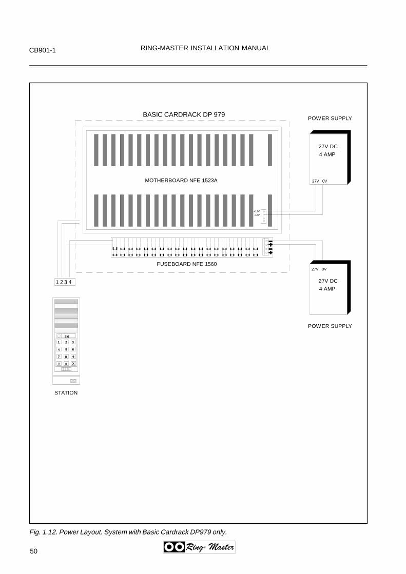
50
CB901-1 RING-MASTER INSTALLATION MANUAL
Ring-Master
Fig. 1.12. Power Layout. System with Basic Cardrack DP979 only.
+12V-12V
MOTHERBOARD NFE 1523A
FUSEBOARD NFE 1560
BASIC CARDRACK DP 979
27V 0V
POWER SUPPLY
POWER SUPPLY
27V DC
4 AMP
27V DC
4 AMP
1 2 3
4 5 6
7 8 9
T 0 X
5 6
1 2 3 4
27V 0V
STATION

RING-MASTER INSTALLATION MANUAL CB901-1
51Ring-Master
Fig. 1.13. Power Layout. System with DP070 and DP980.
MOTHERBOARD NFE 1524A
FUSEBOARD NFE 1560
SUBSCRIBER CARDRACK DP 980
27V 0V
27V DC
4 AMP
27V DC
8 AMP
1 2 3
4 5 6
7 8 9
T 0 X
5 6
1 2 3 4
27V 0V
STATION
POWER SUPPLY
POWER SUPPLY
+12V-12V
MOTHERBOARD NFE 1523A
FUSEBOARD NFE 1560
BASIC CARDRACK DP 979

52
CB901-1 RING-MASTER INSTALLATION MANUAL
Ring-Master
Fig. 1.14. Power Layout. System with All/Group-call, Battery capacity.

RING-MASTER INSTALLATION MANUAL CB901-1
53Ring-Master
Fig. 1.15. Power Layout. System with all/Group-call.
MOTHERBOARD NFE 1524A
FUSEBOARD NFE 1560
SUBSCRIBER CARDRACK DP 980
27V 0V
27V DC
4 AMP
27V DC
12 AMP
1 2 3
4 5 6
7 8 9
T 0 X
5 6
1 2 3 4
27V 0V
STATION
POWER SUPPLY
POWER SUPPLY
+12V-12V
MOTHERBOARD NFE 1523A
FUSEBOARD NFE 1560
BASIC CARDRACK DP 979
BATTERY2 X 12V

54
CB901-1 RING-MASTER INSTALLATION MANUAL
Ring-Master
Fig. 1.16. System with Back-up Batteries. Layout.
MOTHERBOARD NFE 1524A
FUSEBOARD NFE 1560
SUBSCRIBER CARDRACK DP 980
27V 0V
27V DC
1 2 3
4 5 6
7 8 9
T 0 X
5 6
1 2 3 4
STATION
POWER SUPPLY
+12V-12V
MOTHERBOARD NFE 1523A
FUSEBOARD NFE 1560
BASIC CARDRACK DP 979
0V
BATTERY2 X 12V

RING-MASTER INSTALLATION MANUAL CB901-1
55Ring-Master
Fig. 1.17. Table for charger and battery capacity. System with Back-up Battery.
Emergency power operation of Ring-Masterintercom systems.
The CB901 system is as standard operating at27vDc.When calculating the power cable distancebetween the stations and the power supply, weare normally using this value as a refference.When using this value, we can accept a loss of6vDc in the cable.This is equivalent to aproxemately 350 metersfor an AA960 station, when using 0.6mm cable.
When the system is connected to an emergencybattery, the charging voltage will normally be27.2 vDc.However, when the system is supplied from thebattery during mains failure, the voltage will dropto 24vDc, and slowly decrease from this value.The cable distance to the stations willimmediately be reduced to approxemately 180meters.The operating voltage of a system operating onbattery, should therefore be calculated for 24vDcoperation, not 27vDc.But it is not easy to keep the battery voltage at24vDc during the entire emergency periode.The battery voltage will start to drop, after adischarge periode, and this periode will again bedepending on the battery capacity.
Example:A system is specified for 4 hours batteryoperation.
The power consumtion is 100AH.To maintain 24vDc for the entire 4 hours periode,with the specified load, we will need a battery withcapacity between 250 and 300AH.This will give a high cost for the battery and char-ger.Recommendation:We will therefore recommend the use of a 48vDcbattery and charger for larger systems.Between the battery and the installation you mustinstall a DC/DC converter, which will supply asteady 27vDc.The output will be stable 27vDc, for inputsnormally between 36vDc and 76vDc.The units are delivered in the following currentranges:7A, 10A, 14A, 16A and 21A.The units can easily be connected in parallell forincreased power output.
The converter must be calculated to deliver thecurrent required for the complete installation.If All/Call and Group/Call is used, but notprogramme distribution, then a small dryfit batterycan be installed between the DC/DC converterand the installation.The extra current required during the short time forAll/Call, will then be delivered from this battery.
A normal capacity of such a battery is 16 Ah for a240 numbers central.
System current consumption:
Basic Cardset: 1 AEach Subscriber Card: 0.1 AStation in idle: 0.02 AStation ON, talking: 0.1 AStation ON, listening normal level: 0.15 AStation ON, listening max. level: 0.2 AStation ON, listening w/16 ohm parallel speaker: 0.4 A

56
CB901-1 RING-MASTER INSTALLATION MANUAL
Ring-Master
Fig. 1.18. Connection of Alarm/Programme Distribution signals.
PL
UG
RO
W
P2
PL
UG
RO
W
P1
MO
TH
ER
BO
AR
D N
FE
1
52
3A
BA
SIC
CA
RD
RA
CK
DP
979
, R
EA
R
VIE
W.
XA
11
NO
RM
ALL
Y T
HE
PR
OG
RA
MM
E D
ISTR
IBU
TIO
N C
AR
DN
FE
162
6 IS
INS
TALL
ED
IN C
AR
D P
OS
. 10
(XA
11).
FLA
TCA
NLE
NM
F 6
012,
SE
E N
OTE
XA
11X
A10
XA
9X
A8
CA
BLE
NO
. 1. B
F 9
25
CA
BLE
NO
. 2. B
F 9
25
1 A
/B
10 A
/B
23 A
/B
32 A
/B
1234567812
1 (P
OS
)1
(NE
G)
2 (P
OS
)2
(NE
G)
PO
SN
EG
ALA
RM
CH
AN
NE
LS
PR
OG
RA
MM
EC
HA
NN
ELS
ALA
RM
EN
AB
LE
BA
TTE
RY
OP
ER
ATI
ON
NO
TE: W
HE
N T
HE
20-
PA
IR F
LAT
CA
BLE
NM
F 6
012
IS IN
STA
LLE
D
BE
TWE
EN
CA
RD
PO
SIS
TIO
NS
10,
11,
12
AN
D 1
3 (P
LUG
RO
W P
1),
THE
PR
OG
RA
MM
E D
ISTR
IBU
TIO
N C
AR
D N
FE
162
6 (D
P 9
77)
CA
N B
EIN
STA
LLE
D IN
AN
Y O
F T
HE
SE
PO
SIT
ION
S. T
HE
RE
MA
ININ
G T
O B
E
US
ED
FO
R S
UB
SC
RIB
ER
CA
RD
S N
FE
162
5
IF T
HE
CA
BLE
IS N
OT
INS
TALL
ED
, TH
E N
FE
162
6 C
AR
D M
US
T B
E IN
STA
LLE
D I
CA
RD
PO
S. 1
0.

RING-MASTER INSTALLATION MANUAL CB901-1
57Ring-Master
Fig. 1.19. Connector Layout, CPU Card NFE1683.
CONNECTION OF EXTERNAL DEVICES TO 3M TERMINALS OF FLAT CABLE. THE FLATCABLE IS TERMINATED TO THE 64 PIN ROW OF THE CPU CARD, PINS 1A/B TO 32A/B:
27A RTS - - - - 27B CTS 26A RX RS 232 PORT NO. 5 (fixed) 26B GND Service terminal connection (SVT) 25A TX 25B DTR - - - - 24A RTS 24B CTS 23A RX RS 232 PORT NO. 6 (fixed) 23B GND Printer 22A TX 22B DTR - - - - 21A RTS 21B CTS 20A RX RS 232 PORT NO. 4 20B GND Pocket Paging Connection
19A TX 19B DTR - - - - 18A RTS 18B CTS 17A RX RS 232 PORT NO. 3 17B GND Display Driver 16A TX 16B DTR - - - -
Service Terminal9-pin D-connector in front of the NFE 1683. RS 232 serial portpin:
2 RX3 TX4 DTR5 GND7 RTS8 CTS
7A + RX 20 mA current loop. Serial input 7B - - - - - 6A + RX 20 mA current loop. Serial input 6B - - - - - 5A + TX 20 mA current loop. Serial output 5B - - - - - 4A + 4B - RX 20 mA current loop. Stage interconnection. PORT NO. 2.
3A + (Analog link) 3B - TX - - - -
2A + 2B - RX 20 mA current loop. Stage interconnection. PORT NO. 1.
1A + (Analog link) 1B - TX

58
CB901-1 RING-MASTER INSTALLATION MANUAL
Ring-Master
Fig. 1.20. System CB901-1, EMC approved configuration.
Subscriber CardsDP97818 (20) Cards144 (160) Subscribers
SUBSCRIBER CARDRACK DP992
POWERSUPPLY LA92527 Volt DC
Ring-Master S ystem CB901EMC ApprovedCardrack Confi guration
Distibution Frame
Basic Cardset DP952E7 Cards
Subscriber CardsDP97812 (10) Cards96 (80) Subscribers
BASIC CARDRACK DP991
VENTILATION UNIT DP993

RING-MASTER INSTALLATION MANUAL CB901-1
59Ring-Master
Fig. 1.21. Filter Adaptor Layout, DP991 and DP992..
In S
UB
SC
RIB
ER
CA
RD
RA
CK
DP
992:
The
Filte
r Ada
pter
BF
951
mus
t be
inst
alle
d in
the
follo
win
g po
sitio
ns;
3,4,
5,6,
7,8,
9,10
,11
and
12. A
ll 37
pin
D-s
ub ty
pe.
Pos
ition
no.
1: B
us c
able
for d
ata
sign
als,
50
pin
D-s
ubP
ositi
on n
o. 2
: Bus
cab
le fo
r Pro
gram
me
Dis
trib
utio
n/A
larm
sig
nals
, 50
pin
D-s
ubP
ositi
on n
o. 3
: Sub
scrib
er c
ard
no. 2
1 an
d 22
, lin
e eq
uip.
no.
50-
57,5
8-5F
Pos
ition
no.
4: S
ubsc
riber
car
d no
. 23
and
24, l
ine
equi
p. n
o. 6
0-67
,68-
6FP
ositi
on n
o. 5
: Sub
scrib
er c
ard
no. 2
5 an
d 26
, lin
e eq
uip.
no.
70-
77,7
8-7F
Pos
ition
no.
6: S
ubsc
riber
car
d no
. 27
and
28, l
ine
equi
p. n
o. 8
0-87
,88-
8FP
ositi
on n
o. 7
: Sub
scrib
er c
ard
no. 2
9 an
d 30
, lin
e eq
uip.
no.
90-
97,9
8-9F
Pos
ition
no.
8: S
ubsc
riber
car
d no
. 31
and
32, l
ine
equi
p. n
o. A
0-A
7,A
8-A
FP
ositi
on n
o. 9
: Sub
scrib
er c
ard
no. 3
3 an
d 34
, lin
e eq
uip.
no.
B0-
B7,
B8-
BF
Pos
ition
no.
10:
Sub
scrib
er c
ard
no. 3
5 an
d 36
, lin
e eq
uip.
no.
C0-
C7,
C8-
CF
Pos
ition
no.
11:
Sub
scrib
er c
ard
no. 3
7 an
d 38
, lin
e eq
uip.
no.
D0-
D7,
D8-
DF
Pos
ition
no.
12:
Sub
scrib
er c
ard
no. 3
9 an
d 40
, lin
e eq
uip.
no.
E0-
E7,
E8-
EF
Dat
abu
sS
ubs.
00-0
708
-0F
Sub
s.20
-27
28-2
F
Sub
s.40
-47
48-4
F
Pro
g.di
st./
Ala
rm
RS
232
Pro
g.di
st.
bus
Sub
s.10
-17
18-1
F
Sub
s.30
-37
38-3
F
Sub
s.50
-57
58-5
FN
CN
C
13
57
911
24
68
1012
BA
SIC
CA
RD
RA
CK
DP
991
SU
BS
CR
IBE
R C
AR
DR
AC
K D
P99
2
Dat
abu
sS
ubs.
50-5
758
-5F
Sub
s.70
-77
78-7
F
Sub
s.90
-97
98-9
F
Pro
g.di
st.
bus
Sub
s.60
-67
68-6
F
Sub
s.80
-87
88-8
F
Sub
s.A
0-A
7A
8-A
F
13
57
911
24
68
1012
Sub
s.B
0-B
7B
8-B
F
Sub
s.C
0-C
7C
8-C
F
Sub
s.D
0-D
7D
8-D
F
Sub
s.E
0-E
7E
8-E
F
In B
AS
IC C
AR
DR
AC
K D
P99
1:T
he F
ilter
Ada
pter
BF
951
mus
t be
inst
alle
d in
the
follo
win
g po
sitio
ns;
3,4,
5,6,
7,8,
9 an
d 11
. A
ll 37
pin
D-s
ub t
ype.
Pos
ition
no.
1:
Bus
cab
le fo
r da
ta s
igna
ls,
50 p
in D
-su
b.P
ositi
on n
o. 2
: B
us c
able
for
Pro
gram
me
Dis
tibut
ion/
Ala
rm s
igna
ls,
50 p
in D
-su b
Pos
ition
no.
3:
Sub
scrib
er c
ard
no.
1 an
d 2,
line
equ
ip.
no.
00-
07,0
8-0F
Pos
ition
no.
4:
Sub
scrib
er c
ard
no.
3 an
d 4,
line
equ
ip.
no.
10-1
7,18
-1F
Pos
ition
no.
5:
Sub
scrib
er c
ard
no.
5 an
d 6,
line
equ
ip.
no.
20-2
7,28
-2F
Pos
ition
no.
6:
Sub
scrib
er c
ard
no.
7 an
d 8,
line
equ
ip.
no.
30-3
7,38
-3F
Pos
ition
no.
7:
Sub
scrib
er c
ard
no.
9 an
d 10
, lin
e eq
uip.
no.
40-
47,4
8-4F
Pos
ition
no.
8:
Sub
scrib
er c
ard
no.
11 a
nd 1
2, li
ne e
quip
. no
. 50
-57,
58-5
F
Pos
ition
no.
9:
Pro
gram
me
Dis
trib
utio
n/A
larm
car
dP
ositi
on n
o. 1
0: N
ot c
onne
cted
Pos
ition
no.
11:
RS
232
Ser
ial d
ata
inte
rfac
e ca
ble
Pos
ition
no.
12:
Not
con
nect
ed
For
opt
ical
fibr
e, C
B90
1-2/
-3/-
M
For
pow
er s
uppl
y le
ads
Fig
. 3.
21

60
CB901-1 RING-MASTER INSTALLATION MANUAL
Ring-Master
Fig. 1.22. Installation Internal Subscriber Cable BF950 in DP991 and DP992.
BA
SIC
CA
RD
RA
CK
DP
991
00 0708 0F
10 1718 1F
20 27
Scr
ew te
rmin
al fo
r po
wer
conn
ectio
n
Inte
rnal
Sub
scrib
er C
able
B
F95
0
12V
12V
28 2F30 37
38 3F40 47
48 4F
Hol
e fo
r le
ads
from
pow
er
unit
50 5758 5F

RIN
G-M
AS
TE
R IN
ST
ALLA
TIO
N M
AN
UA
LC
B901-1
61Ring-
Master
Fig.1.23. Installation Internal B
us Cable B
F954 for P
rogramm
e Distribution/A
larm feature.
BASIC CARDRACK DP991
0007
080F
1017
181F
2027
12V
12VPin 1A/B
Pin 32A/B
Plug connectionpins 12A/B - 31A/B
Pins 32A/B MUST NOTbe connected
Pin 1A/B
Pin 32A/B
Plug connectionpins 1A/B - 20A/B
The wires for 0V and -5V should be soldered to 0V and -5V on the Motherboard NFE1523A
Fig. 3.23
282F
3037
383F
4047
484F
5057
585F
Internal Bus Cable for data signals, BF955
Internal Bus Cable for programme didtribution/Alarm signals, BF954
0V-5V
+12V- 12V
0 V
Solder 0V wires
Solder -5V wires

62
CB901-1 RING-MASTER INSTALLATION MANUAL
Ring-Master
Fig. 1.24. Installation Internal RS232 Cable BF957 in DP991.
BA
SIC
CA
RD
RA
CK
DP
991
00 0708 0F
10 1718 1F
20 27
12V
12V
Fig
. 3
.24
Pin
32A
/B
Plu
g co
nnec
tion
pins
16A
/B -
27A
/B
Pin
1A
/B
Inte
rnal
RS
232
Cab
le, B
F95
7
28 2F30 37
38 3F40 47
48 4F50 57
58 5F
Plu
g co
nnec
tion
pins
1A
/B -
7A/B

RING-MASTER INSTALLATION MANUAL CB901-1
63Ring-Master
Fig. 1.25. Installation Internal Cable BF958 for Programme Distribution/Alarm in DP991
BA
SIC
CA
RD
RA
CK
DP
991
00 0708 0F
10 1718 1F
20 27
12V
12V
Fig
. 3.
25
Inte
rnal
Cab
le fo
r P
rogr
amm
e D
istr
ibut
ion/
Ala
rm
sign
als,
BF
958
28 2F30 37
38 3F40 47
48 4F50 57
58 5F
Plu
g co
nnec
tion
pins
1A
/B -
20A
/BC
able
NM
F60
12
Plu
g co
nnec
tion
pins
23A
/B -
32A
/B
Pin
1A
/B
Pin
32A
/B

64
CB
901-1R
ING
-MA
ST
ER
INS
TA
LLAT
ION
MA
NU
AL
Ring-
Master
Fig. 1.26. Installation E
xternal Bus C
able BF
956 for Data and P
rogramm
e Distribution/A
larm.
Databus
Prog.dist.bus
1 3 5 7 9 11
2 4 6 8 10 12
BASIC CARDRACK DP991
SUBSCRIBER CARDRACK DP992
Databus
Prog.dist.bus
1 3 5 7 9 11
2 4 6 8 10 12
External Bus Cable BF956 for Data
External Bus Cable BF956 for Programme Distribution/Alarm signals

RIN
G-M
AS
TE
R IN
ST
ALLA
TIO
N M
AN
UA
LC
B901-1
65Ring-
Master
Fig. 1.27. Installation E
xternal RS
232 Cable B
F952/B
F952A
in DP
991.
1 white 1 RTS blue 20 CTS PORT NO. 52 white 2 RX orange 21 GND Service Terminal RS2323 white 3 TX green 22 DTR connection (SVT)4 white 4 RTS brown 23 CTS PORT NO. 65 white 5 RX grey 24 GND Printer RS2326 red 6 TX blue 25 DTR7 red 7 RTS orange 26 CTS PORT NO. 48 red 8 RX green 27 GND Radio Paging RS2329 red 9 TX brown 28 DTR10 red 10 RTS grey 29 CTS PORT NO. 311 black 11 RX blue 30 GND (SVIM)12 black 12 TX orange 31 DTR13 black 13 RX+ green 27 RX- Serial input 20mA current loop14 black 14 TX+ brown 33 TX- Serial output 20mA current loo15 black 15 RX+ grey 34 RX- PORT NO. 216 yellow 16 TX+ blue 35 TX- Stage interconnection17 yellow 17 RX+ orange 36 RX- PORT NO. 118 yellow 18 TX+ green 37 TX- Stage Interconnection19 yellow 19 brown nc20 yellow nc grey nc
Pair no: ColourA-wire
Pin nos.D-sub:
ColourB-wire:
Pin nos.D-sub:
Termination of External RS232 Cable BF952/BF952A, 20 pair cable with 37 pin D-sub connector. The IEC colour coding standard is used.
RS232signal:
RS232signal:
Functionaldescription:
20 pair cable, ending in loose ends
External RS232/Subscriber Cable BF952, 3 meter.
External RS232/Subscriber Cable BF952A, 10 meter.
Pin 1
Pin 37

66
CB
901-1R
ING
-MA
ST
ER
INS
TA
LLAT
ION
MA
NU
AL
Ring-
Master
Fig. 1.28. Installation E
xternal Program
me D
istribution/Alarm
Cable B
F952/B
F952A
in DP
991.
1 white 1 Alarm ch. 2 blue 20 Alarm ch. 22 white 2 Alarm ch. 1 orange 21 Alarm ch. 13 white 3 Prog. dis. 8 green 22 Prog. dis. 84 white 4 Prog. dis. 7 brown 23 Prog. dis. 75 white 5 Prog. dis. 6 grey 24 Prog. dis. 66 red 6 Prog. dis. 5 blue 25 Prog. dis. 57 red 7 Prog. dis. 4 orange 26 Prog. dis. 48 red 8 Prog. dis. 3 green 27 Prog. dis. 39 red 9 Prog. dis. 2 brown 28 Prog. dis. 210 red 10 Prog. dis. 1 grey 29 Prog. dis. 111 black 11 AEC1,Pblue 30 AEC1,N12 black 12 AEC2,Porange 31 AEC2,N13 black 13 Batt. op. pos green 27 Batt. op. neg14 black 14 brown 3315 black 15 grey 3416 yellow 16 blue 3517 yellow 17 orange 3618 yellow 18 green 3719 yellow 19 brown nc20 yellow nc grey nc
Pair no: ColourA-wire
Pin nos.D-sub:
ColourB-wire:
Pin nos.D-sub:
Termination of External Programme Distribution/Alarm Cable BF952/BF952A, 20 pair cable with 37 pin D-sub connector. The IEC colour coding standard is used.
20 pair cable, ending in loose ends
External Programme Distr./Alarm Cable BF952, 3 meter.
External Programme Distr./Alarm Cable BF952A, 10 meter.
Pin 1
Pin 37
Prog. Dist.signal:
Prog. Dist.signal:
Alarm Enable Channel no. 1, positive = AEC1,PAlarm Enable Channel no. 1, negative = AEC1,NAlarm Enable Channel no. 2, positive = AEC2,PAlarm Enable Channel no. 2, negative = AEC2,NBattery operation, positive = Batt. op.posBattery operation, negative = Batt. op.neg

RIN
G-M
AS
TE
R IN
ST
ALLA
TIO
N M
AN
UA
LC
B901-1
67Ring-
Master
Fig. 1.29. Installation E
xternal Subscriber C
able BF
952/BF
952A in D
P991 and D
P992.
1 white 1 blue 20 00/10/20/30/40/50/60/70/80/90/A0/B0/C0/D0/E2 white 2 orange 21 013 white 3 green 22 024 white 4 brown 23 035 white 5 grey 24 046 red 6 blue 25 057 red 7 orange 26 068 red 8 green 27 079 red 9 brown 28 0810 red 10 grey 29 0911 black 11 blue 30 0A12 black 12 orange 31 0B13 black 13 green 27 0C14 black 14 brown 33 0D15 black 15 grey 34 0E16 yellow 16 blue 35 0F17 yellow 17 orange 3618 yellow 18 green 3719 yellow 19 brown nc20 yellow nc grey nc
1
8
81
Pair no: Colourwire 1:
Pin nos.D-sub:
Colourwire 2:
Pin nos.D-sub:
Station line pos. nos:
Firs
t sub
scrib
er
ca
rdS
econ
d su
bscr
iber
car
d
Termination of External Subscriber Cable BF952/BF952A, 20 pair cable with 37 pin D-sub connector. The IEC colour codin g standard is used.
20 pair cable, ending in loose ends
External Subscriber Cable BF952, 3 meter.External Subscriber Cable BF952A, 10 meter.
Pin 1
Pin 37
1
Fig. 3.29

68
CB
901-1R
ING
-MA
ST
ER
INS
TA
LLAT
ION
MA
NU
AL
Ring-
Master
Expanding Ring-Master System CB901.Expanding an existing CB901 system with a new EMC approved Subscriber Cardrack DP992.
D-Sub connector on interconnect cable BF956(for internal data and audio).
D-Sub connector on interconnect cable BF956(for programme distribution and all-call audio).
Flat cable BF955
Flat cable BF954
Mounting brackets for 3M terminals in backplate
The Subscriber Cardrack DP980 is no longer delivered in areas where EMC approved equipmrequired.RingCom AS will only supply the EMC approveSubscriber Cardrack DP992 when expanding aexisting CB901 system, where the (not EMC approved) cardrack DP979 is already installed.The DP992 includes all necessary interconnectcables.See the photo/drawing to the left which indicatewhere to locate the D-Sub connectors on the baplate of DP979.Please see the Ring-Master Installation Manua(WWT-50E), page 76 and 111 for termination ofInternal Bus Cable BF955 (power wires to the Dmotherboard NFE1523A).
Subscriber Cardrack DP979 with installed interconnect cables BF956 for EMC Subscriber Cardrack DP992
Fig. 1.30. E
xpansion of existing non EM
C approved system
with new
EM
C approved S
ubscr. Cardrack D
P992.

38
RM5000 RING-MASTER INSTALLATION MANUAL
Ring-Master
The company reserves the right to modify designs and alter specifications without notice, in pursuance of a policy of continuous improvement.
F A S T A C C E S S C O M M U N I C A T I O N
July 98
Alpha Communications42 Central Drive - Farmingdale NY 11735-1202Phone (631) 777-5500 Fax (631) 777-5599Internet: http:/www.alpha-comm.comEmail: [email protected]