installation manual · refer to the next page for a wifi system map example using a poe injector....
TRANSCRIPT

Version: VIPSLRB-Q219
SLR-B Solar CCTV SeriesInstallation Manual

VIP Vision SLR-B Solar Surveillance Installation Manual - Version: VIPSLRB-Q2192
1. Pre-Install Information
Thank you for purchasing a SLR-B Series Solar Surveillance System.This install guide covers basic setup, installation and use of your surveillance system.
For more information, please visit: www.vip-vision.com

Visit www.vip-vision.com for support 3
# Part Product Code Image
1x Solar Panel(w/ remote control device)
SSL-B50MN (50W)
SSL-B60MN (60W)
1x 4.0MP Mini PTZ Dome Camera VSIP4MPPTZMINI
1x Camera Adapter VSBKTA106
1x Right Angle Bracket VSBKTB305W
1x Junction Box VSBKTA140
1x Pole Mount Bracket VSBKTA150
1x 128GB microSD card MICROSD128GB
2xUbiquiti 5.8GHz 120° Wireless
Bridge (1x Access Point, 1x Station) (WiFi system only)
WT5-ULB
1x Huawei 4G Modem Router with WiFi (4G system only) VSWAN4GHWI
Pole, base plate & SIM card not included.
Required Install Tools: Allen key for junction box (included), 4mm & 10mm Allen keys for solar panel (not included), 8mm drill bit & battery drill, flat head screwdriver. Laptop with RJ45 network interface strongly recommended for camera setup.
1.1 Included Components
VIP Vision SLR-B Solar Surveillance Installation Manual - Version: VIPSLRB-Q2194
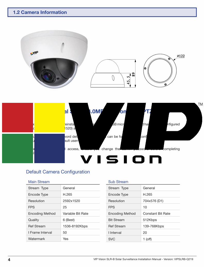
Professional Series 4.0MP 4x Zoom Mini PTZ Dome
Note: Camera has been preinstalled with the supplied 128GB microSD card and has been preconfigured to record 4.0MP (2592 x 1520) at 25fps.
The username and password details for the camera can be found on the configuration sheet inside the junction box. The default username is admin.
To prevent unauthorised access, ensure you change the admin password before completing installation.
Default Camera Configuration
Main Stream
Stream Type General
Encode Type H.265
Resolution 2592x1520
FPS 25
Encoding Method Variable Bit Rate
Quality 6 (Best)
Ref Stream 1536-8192Kbps
I Frame Interval 50
Watermark Yes
Sub Stream
Stream Type General
Encode Type H.265
Resolution 704x576 (D1)
FPS 10
Encoding Method Constant Bit Rate
Bit Stream 512Kbps
Ref Stream 139-768Kbps
I Interval 20
SVC 1 (off)
1.2 Camera Information

Visit www.vip-vision.com for support 5
Motion Sensing Solar Panel with 50W Street Light
Solar Panel Specifications
Panel Type 120W monocrystalline silicon panel
Battery 12.8V/500Wh Lithium Iron Phosphate (LiFePO4) w/ Low Voltage Cutoff
Panel Tilt Adjust -60° ~ 60°
Ingress Protection (Panel) IP66
Wind Tolerance Up to 65m/s
Dimensions (Panel) 1321 x 525 x 161mm
Pole Diameter (Spigot) Ø60mm
Note: This solar panel system is fitted with undervoltage protection, which disconnects the load at approximately 10.8V. If you are not receiving any voltage on the output wires, place the panel in direct sunlight for a minimum of one hour and re-test. The output will be reconnected automatically when battery voltage reaches approximately 11.5V.
Must be installed in direct sunlight. Shade will negatively impact performance.
This solar panel includes a motion-activated LED light. For more information, refer to 4. Solar Panel LED Configuration.
1.3 Solar Panel Information

VIP Vision SLR-B Solar Surveillance Installation Manual - Version: VIPSLRB-Q2196
Solar Panel Dimensions
Solar Panel Assembly Diagram
Lamp Body
Bird Spikes
1.3 Solar Panel Information (continued)

Visit www.vip-vision.com for support 7
1. Drill an 8mm hole in the pole (minimum 15cm down from the top of the pole) on the same side that the camera will be mounted. This is for the solar panel cable to run through. The position of the hole will vary depending on what position on the pole the camera is to be mounted.
2. Feed the twin power cable connected to your solar panel through that hole
3. Place the solar panel bracket on top of the pole, pointing north.
• Note: If you need to cover a different area with the light beam, keep the panel flat after repositioning .
4. Securely fasten the included grub screws to the bracket. Tighten the locking bolts to prevent the grub screws from loosening. (Fig. 2.1b)
• Note: For poles greater than 4m in height, tapered poles are preferable for camera stability and pole strength.
8mm
Fig. 2.1a Solar panel power cable drill location
Fig. 2.1b Installed grub screws
Caution: Solar panel must be placed so it is in direct sunlight all day.
Any shading will greatly reduce the solar panel’s performance!
2. Installation
2.1 Mounting the Solar Panel to the Pole

VIP Vision SLR-B Solar Surveillance Installation Manual - Version: VIPSLRB-Q2198
1. Use a flat head screwdriver to remove the bracket cover (Fig. 2.2a).
2. Once the cover is removed, loosen the Allen head to adjust the solar panel angle (Fig. 2.2b).
To ensure your solar panel absorbs as much light as possible, it’s important to adjust the solar panel angle to an ideal angle, depending on your region (refer to table below).
3. Tighten the bolt after adjusting the angle to secure the solar panel in place.
4. Replace the cover.
Note: Ideally, the panel must point north with the correct angle from the table above. Please contact VIP Vision for cities outside of Australia.
To ensure the solar panel works efficiently, it will require regular cleaning. The lower the angle the solar panel is positioned (flatter), the more often it will need to be cleaned.
Ideal panel angles (H°) by Australian city
Sydney Melbourne Perth Brisbane Hobart Adelaide Darwin
34° 38° 32° 27.5° 43° 35° 12.5°
Fig. 2.2a Solar panel angle adjust cover
Fig. 2.2b Solar panel angle adjust Allen head
2.2 Adjusting the Solar Panel Angle

Visit www.vip-vision.com for support 9
A
B
C
D
E
65-89mmBand Clamps
F
# Part Product Code
A Camera VSIP4MPPTZMINI
B Camera Adapter VSBKTA106
C Right Angle Bracket VSBKTB305W
D Junction Box VSBKTA140
E Pole Mount Bracket VSBKTA150
F Pole Not supplied
The camera, camera adapter, right angle bracket and junction box are already connected (A, B, C & D).
• Mount the pole mount bracket to the pole first.
• After the pole mount is installed, mount the junction box to the pole mount.
• Open the junction box and tighten the screws inside to securely fasten it to the pole mount.
2.3 Mounting the Camera to the Pole

VIP Vision SLR-B Solar Surveillance Installation Manual - Version: VIPSLRB-Q21910
1. Mount the pole mount bracket onto the pole using 3 included band clamps (Fig. 2.3b).
Note: The 3 included band clamps are 65-89mm for poles 50-60mm in diameter. If installing on a thicker pole (eg. 80-150mm), larger band clamps will be required.
Fig. 2.3a Mounted pole bracket (front)
Fig. 2.3b Mounted pole bracket (back)
2.3 Mounting the Camera to the Pole (continued)

Visit www.vip-vision.com for support 11
Fig. 2.3c Junction box interior (no 4G router)
2. Open the junction box (Fig. 2.3c).
Note: This image shows the inside of the junction box as seen with the WiFi kit. The 4G kit will also have the 4G router pre-installed inside the junction box.
2.3 Mounting the Camera to the Pole (continued)

VIP Vision SLR-B Solar Surveillance Installation Manual - Version: VIPSLRB-Q21912
4. Run the power cable coming from the solar panel through one of the cable holes of the junction box.
5. Carefully connect the solar panel power cable to the terminal block, with the red wire connecting to + and the black wire connecting to -. (Fig. 2.3f)
Fig. 2.3f Solar battery cables connected to terminal block
Fig. 2.3e Terminal block
Caution: Do not allow the negative and positive power supply wires from the solar panel to touch (short circuit) - this will cause the lithium polymer battery to enter protection mode and output voltage will drop to 0V.
The only way to recover from this is to disconnect and then reconnect the battery inside the panel - Please contact VIP Vision™ for further details.
When running cables, insulation should be removed from each end and cut carefully, ensuring each end does not touch each other.
2.3 Mounting the Camera to the Pole (continued)
Visit www.vip-vision.com for support 13
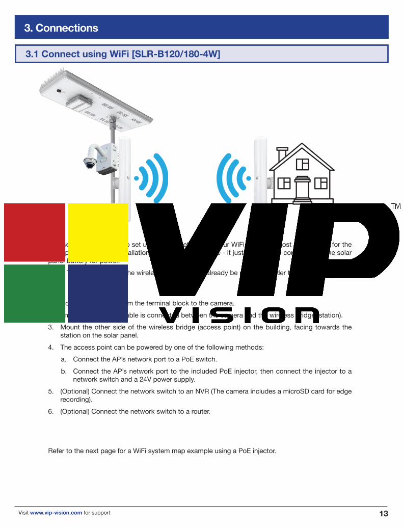
1. Connect a DC jack from the terminal block to the camera.
2. Ensure the Ethernet cable is connected between the camera and the wireless bridge (station).
3. Mount the other side of the wireless bridge (access point) on the building, facing towards the station on the solar panel.
4. The access point can be powered by one of the following methods:
a. Connect the AP’s network port to a PoE switch.
b. Connect the AP’s network port to the included PoE injector, then connect the injector to a network switch and a 24V power supply.
5. (Optional) Connect the network switch to an NVR (The camera includes a microSD card for edge recording).
6. (Optional) Connect the network switch to a router.
Refer to the next page for a WiFi system map example using a PoE injector.
This section covers how to set up the WiFi network for your WiFi Solar Kit. Most of the setup for the solar panel side of the installation has already been done - it just needs to be connected to the solar panel battery for power.
Note: The station side of the wireless bridge should already be mounted under the solar panel.
3. Connections
3.1 Connect using WiFi [SLR-B120/180-4W]

VIP Vision SLR-B Solar Surveillance Installation Manual - Version: VIPSLRB-Q21914
Fig. 3.1a Example WiFi Setup
NVR (optional)
Router (optional)
Internet
Network Switch
Ethernet
Power
WiFi
Wireless Bridge (Station)
Camera
Solar Panel
Wireless Bridge (AP)
24V PoE InjectorDO NOT USE 802.3ac (48V) PoE Injector
240VAC Power
3.1 Connect using WiFi [SLR-B120/180-4W] (continued)

Visit www.vip-vision.com for support 15
1. Insert an active SIM card into the SIM slot.
2. Connect a DC jack from the terminal block to the 4G router.
3. Connect the other DC jack from the terminal block to the camera.
4. (Optional) Connect an antenna to the 4G router to improve signal strength (not included).
NOTE: 4G setup requires an active SIM card (not included). For more information on how to configure the 4G router, refer to the 4G router manual (included).
Camera connected via Ethernet cable
12VDC power
Antenna (optional)
SIM card slot
Fig. 3.2a 4G router overview
3.2 Connect using 4G [SLR-B120/180-4G]

VIP Vision SLR-B Solar Surveillance Installation Manual - Version: VIPSLRB-Q21916
3.2 Connect using 4G [SLR-B120/180-4G] (continued)
Camera & 4G router connected via RJ45
4G router powered via terminal block
Battery/terminal block connection
Camera powered via terminal block
Fig. 3.2b Connection overview

Visit www.vip-vision.com for support 17
1. Install the free app from the App Store for iOS (iDMSS Plus) or Play Store for Android (gDMSS Plus).
2. Open the iDMSS Plus/gDMSS Plus app you have installed on your device and select “Camera”
3. Select Menu, then select “Device Manager”. (Fig. 3.2c)
4. Press the “Add” button and tap “OK” when prompted.
5. Select “Wired device”
6. Select “P2P” & enter a name for the camera. This name is for reference only and can be set to anything.
7. Enter the serial number of the camera into the “SN:” text box, OR select the image of the QR code (pictured) and use your phone to scan the QR code included with the kit. Make sure the app is permitted to access your phone’s camera.
8. Enter the default username admin and password (refer to configuration sheet inside junction box). For extra security, be sure to change these details before completing installation.
9. In Live Preview, you can choose between using Main or Extra stream. (Fig. 3.2e) Main displays a higher quality stream but uses up more data and has a slower connection, while Extra consumes less data and bandwidth but has lower image quality.
10. When using Playback, ensure that Live Preview is set to Main. If set to Extra, the screen will be black. This is because the camera has been preset to only record the Main stream to the microSD card (you can change this setting).
11. Select “Start Live Preview”. If the details were entered correctly, your phone should connect to your recorder and you will see the live camera display.
For more information on how to configure the camera, refer to the camera’s Quick Start Guide.
Internet access is reuiqres for remote access setup.
QR code remote access setup (4G)
Fig. 3.2d Camera details
Fig. 3.2e Live Preview stream
selection
Fig. 3.2c Main Menu
3.2 Connect using 4G [SLR-B120/180-4G] (continued)

VIP Vision SLR-B Solar Surveillance Installation Manual - Version: VIPSLRB-Q21918
Close the junction box and securely fasten the 4 attached bolts (Fig. 3.3a).
Fig. 3.3a Complete solar surveillance system
3.3 Finish Camera Installation

Visit www.vip-vision.com for support 19
Note: Enabling the LED light and sensor will increase power consumption and reduce battery power available for the CCTV system.
Incorrectly editing power settings can permanantly damage the solar panel, solar battery and/or LED light. Consult your VIP Vision professional for more information. Only edit power settings exactly as outlined in this guide.
This section covers how to set up the motion-activated 50W LED light on the solar panel. Our example will show you how to configure your solar panel & light with the remote control, showing you the steps required to set up the light to activate after motion is detected at night.
With this setup, the solar panel can double as a motion-actived security light at night, as well as a network CCTV system.
The solar panel’s motion-activated LED light is disabled by default. Solar panel configuration requires the remote control (provided on request).
1. Battery Type: Type of battery installed in the solar panel (Li_Po=LiFePO4 battery or Lead acid). Warning: SLR-B120 uses LiFePO4 battery, DO NOT change this parameter.
2. Boost Charge: Battery overcharge voltage. To protect the battery from overcharging, the battery stops charging when it is above this voltage.
3. Voltage Low: Battery cut-off voltage. When the battery voltage falls below this value, output will be disabled.
4. Recover Voltage: Minimum voltage for the battery to start. Battery output is enabled or resumed from cut-off when battery voltage is above this value.
5. Power Saving: When turned on, the battery will adjust power output automatically to save energy (On/Off).
6. Turn-On PV Voltage: The light turns on when the solar panel is below this voltage (dark). Note: LED light turns on/off condition must meet other settings.
7. Output Current: Set the constant current output level.
8. Drive Mode: Time Control - 5 individual intervals of maximum 9 hours each can be set to turn LED light on. Move Sensor - Motion detect. The LED light will switch to higher intensity when it detects movement. If no movement is detected, the intensity will be lower to save power. The intensity can be adjusted for both settings to meet customer’s requirements.
9. Light Delay: The on-time delay after last detection motion. Suggested value: 30 seconds.
10. First/Second/Third/Fourth/Fifth Time: User-programmable light on/off schedule. Maximum 9 hours for each setting.
11. Light Ratio: Set light output (%) for when movement is detected.
12. Idle ratio: Set light output (%) for when no movement is detected.
Understanding Settings:
Before adjusting solar panel settings, familiarise yourself with the setting definitions below:
4. Solar Sensor Light Configuration (Optional)
4.1 Solar Sensor Light Introduction

VIP Vision SLR-B Solar Surveillance Installation Manual - Version: VIPSLRB-Q21920
Default pre-delivery time control settings:
Battery and charging settings: (DO NOT ADJUST)
Overcharge Protection Voltage (Boost Charge): 14.2VCut-off Voltage (Voltage Low): 11.0VStart Up Voltage (Recover Voltage): 12.0VWarning: Changing the above settings may damage the battery and charging circuit.
Period Light Ratio Idle Ration
First Time 9 Hours 10% 0%
Second Time 9 Hours 10% 0%
4.2 Default Settings
4.3 Remote Control
1. Take the solar panel outside and wait for it to charge in the sunlight for at least one hour.
2. Use the remote control and point it towards the black sensor at the back of the solar panel and press Power. The remote control will be powered up. It will then try to connect the solar panel.
• If connection is successful, the LCD will show “Read OK”.
• If connection fails, the LCD will show “Disconnect” Note: Direct sunlight can interfere with the transmission. The sensitivity of the transmitter is higher when in dark environment.
Important: Do not change the device number otherwise it may not work properly. The device number for this system is: PCC_G05
3. Press and hold the ON button to enable the solar light.
Fig. 4.3a Solar panel remote control
Fig. 4.3b Remote control LCD

Visit www.vip-vision.com for support 21
Power Press to power on. Press and hold for 2 seconds, then release to power off the remote control.
Scroll Up Press to scroll up.
Scroll Down Press to scroll down.
Controller On Press and hold to enable the LED light control.
Controller Off Press and hold to disable the LED light control.
Enter Press to select item or confirm changes.
Back Press to select item or confirm changes.
Transmit Press to transmit parameters to the control board.
Test Press to test the LED light.
4.3 Remote Control (continued)
4. Point the remote control at the solar panel’s black sensor and scroll to the SysConfig (System Configure) and press (Enter) to enter the system configuration menu.
• Use and to scroll.
• Press Enter to begin editing values. The value will be shown in reverse colour.
• Use and to change the value.
• Press Enter again to confirm.
Note: The remote will power off automatically if no key is pressed for 3 minutes.
Five periods of time can be set to turn on the solar panel LED light. These periods can be set with a min. of 0 and max. of 9 hours.
5. Point the remote control at the solar panel’s black sensor and press Transmit to update the solar panel with your new configuration. If you hear a long beep, the configuration settings are transmitted succesfully.

VIP Vision SLR-B Solar Surveillance Installation Manual - Version: VIPSLRB-Q21922
4.4 Disable Motion Activated LED Light
4.5 Check Solar Pabel On/Off Duration
4.6 Test LED Light
4.7 Lock/Unlock the Remote Control
To disable the LED light system again, simply change the Drive Mode from Move Sensor to Time Ctrl. This will skip every Interval after the sun sets, so editing other values after this point is unnecessary.
To check the solar panel’s current settings configuration, scroll to the SysConfig menu and press Enter. This will show info such as photovoltaic voltage, battery voltage, output voltage, current and power, temperature and total operating time in minutes and more.
1. Point the remote control at the solar panel’s black sensor and press Test.
2. Test the LED light by adjusting the light level on the remote screen with the Test button. This scrolls through different light percentages. (100%, 70%, 50%, 30% and 0%)
After setup has been completed, you can lock the remote control to prevent changing the parameters accidentally.
To lock/Unlock the remote control, press the Test, Enter and Back buttons together.
If you hear a single beep, the remote is locked. If you hear three beeps, the remote is unlocked.

Visit www.vip-vision.com for support 23
I can't connect to the camera using the QR code.
• Ensure that your camera is powered on power. • Check that the inserted SIM card is active.
Video footage is slow/laggy/choppy.
• Ensure that your camera is in an area with good mobile service coverage and that only one user is viewing the system at once.
1. Switch your mobile device to view the Extra (sub) stream instead of Main to use less bandwidth.
My camera doesn't have power.
• Check the connections from the solar panel battery to the camera.• If the battery is out of power, the camera should automatically turn on once the solar panel
absorbs more light.
5. Troubleshooting
Notes

Note:
All products, designs and software here are subject to change without prior written notice.
Version: VIPSLRB-Q219