installation manual - master group · 2017-12-08 · mercury is a hazardous substance, if existing...
TRANSCRIPT

HxTM TOUCH SCREEN THERMOSTAT
MODELS: S1-THXU280B & S1-THXU280W
INSTALLATION MANUAL
LIST OF SECTIONSGENERAL . . . . . . . . . . . . . . . . . . . . . . . . . . . . . . . . . . . . . . . . . . . . . . 1SAFETY CONSIDERATIONS . . . . . . . . . . . . . . . . . . . . . . . . . . . . . . . 1INSTALLATION . . . . . . . . . . . . . . . . . . . . . . . . . . . . . . . . . . . . . . . . . . 2WIRING COMMUNICATION . . . . . . . . . . . . . . . . . . . . . . . . . . . . . . . . 3
INITIAL POWER-UP . . . . . . . . . . . . . . . . . . . . . . . . . . . . . . . . . . . . . 9SERVICE MODE . . . . . . . . . . . . . . . . . . . . . . . . . . . . . . . . . . . . . . . 11SERVICE SETTINGS . . . . . . . . . . . . . . . . . . . . . . . . . . . . . . . . . . . . 20
LIST OF FIGURESControl Location . . . . . . . . . . . . . . . . . . . . . . . . . . . . . . . . . . . . . . . . . . 2High Level Wiring Path . . . . . . . . . . . . . . . . . . . . . . . . . . . . . . . . . . . . . 3Communicating Plug Harness . . . . . . . . . . . . . . . . . . . . . . . . . . . . . . . 3Wiring Diagram (Fully Communicating System Components) . . . . . . . 4Wiring Diagram (Variable Capacity System) . . . . . . . . . . . . . . . . . . . . 4Wiring Diagram (Modulating Communicating Furnace, Non-Communicating AC) . . . . . . . . . . . . . . . . . . . . . . . . . . . . . . . . . . . 4Outdoor Communicating Terminals . . . . . . . . . . . . . . . . . . . . . . . . . . . 4Variable Speed Capacity AC/Heat Pump Control . . . . . . . . . . . . . . . . 4Outdoor Control Housing . . . . . . . . . . . . . . . . . . . . . . . . . . . . . . . . . . . 5Typical Communicating Field Wiring (Variable Capacity outdoor unit) . . . . . . . . . . . . . . . . . . . . . . . . . . . . . . 5Multi-wire Terminal Connection . . . . . . . . . . . . . . . . . . . . . . . . . . . . . . 6Communicating Indoor Controls - Air Handler . . . . . . . . . . . . . . . . . . . 6Communicating Indoor Controls - Furnaces . . . . . . . . . . . . . . . . . . . . 7Indoor Screw Terminal Location . . . . . . . . . . . . . . . . . . . . . . . . . . . . . 8Furnace Bypass . . . . . . . . . . . . . . . . . . . . . . . . . . . . . . . . . . . . . . . . . . 8Air Handler Bypass . . . . . . . . . . . . . . . . . . . . . . . . . . . . . . . . . . . . . . . 8
Furnace Fan Powered . . . . . . . . . . . . . . . . . . . . . . . . . . . . . . . . . . . . 9Air Handler Fan Powered . . . . . . . . . . . . . . . . . . . . . . . . . . . . . . . . . . 9Auto Setup . . . . . . . . . . . . . . . . . . . . . . . . . . . . . . . . . . . . . . . . . . . . . 9ID Search . . . . . . . . . . . . . . . . . . . . . . . . . . . . . . . . . . . . . . . . . . . . . . 9Found Mod Furnace . . . . . . . . . . . . . . . . . . . . . . . . . . . . . . . . . . . . . 10OD Search . . . . . . . . . . . . . . . . . . . . . . . . . . . . . . . . . . . . . . . . . . . . 10YGVI . . . . . . . . . . . . . . . . . . . . . . . . . . . . . . . . . . . . . . . . . . . . . . . . . 10Heat Kit . . . . . . . . . . . . . . . . . . . . . . . . . . . . . . . . . . . . . . . . . . . . . . . 10Electric Heat Size - W1 4.2 . . . . . . . . . . . . . . . . . . . . . . . . . . . . . . . . 10Electric Heat Size - W2 12.5 . . . . . . . . . . . . . . . . . . . . . . . . . . . . . . . 10Screen Settings . . . . . . . . . . . . . . . . . . . . . . . . . . . . . . . . . . . . . . . . 11Screen System Set Faults . . . . . . . . . . . . . . . . . . . . . . . . . . . . . . . . 13Vent with Heat . . . . . . . . . . . . . . . . . . . . . . . . . . . . . . . . . . . . . . . . . 19Log . . . . . . . . . . . . . . . . . . . . . . . . . . . . . . . . . . . . . . . . . . . . . . . . . . 20Screen Log Startup . . . . . . . . . . . . . . . . . . . . . . . . . . . . . . . . . . . . . . 20Screen Service . . . . . . . . . . . . . . . . . . . . . . . . . . . . . . . . . . . . . . . . . 20Status . . . . . . . . . . . . . . . . . . . . . . . . . . . . . . . . . . . . . . . . . . . . . . . . 20
LIST OF TABLESContent List . . . . . . . . . . . . . . . . . . . . . . . . . . . . . . . . . . . . . . . . . . . . . 3Terminal Designations . . . . . . . . . . . . . . . . . . . . . . . . . . . . . . . . . . . . . 4Outdoor Jumper Settings . . . . . . . . . . . . . . . . . . . . . . . . . . . . . . . . . . . 6Indoor Jumper Settings . . . . . . . . . . . . . . . . . . . . . . . . . . . . . . . . . . . . 8Equipment Settings . . . . . . . . . . . . . . . . . . . . . . . . . . . . . . . . . . . . . . 12Float Switch Settings (AHV, AVC, and 2-Stage Variable Speed ECM Furnace) . . . . . . . . . . . . . . . . . . . . . . . 14Auxiliary Settings (2-Stage Variable Speed ECM Furnace) . . . . . . . . 14
Faults . . . . . . . . . . . . . . . . . . . . . . . . . . . . . . . . . . . . . . . . . . . . . . . . 14Critical Faults . . . . . . . . . . . . . . . . . . . . . . . . . . . . . . . . . . . . . . . . . . 15Efficiency Fault . . . . . . . . . . . . . . . . . . . . . . . . . . . . . . . . . . . . . . . . . 18Warning Fault . . . . . . . . . . . . . . . . . . . . . . . . . . . . . . . . . . . . . . . . . . 19Status Fault . . . . . . . . . . . . . . . . . . . . . . . . . . . . . . . . . . . . . . . . . . . . 19System Events . . . . . . . . . . . . . . . . . . . . . . . . . . . . . . . . . . . . . . . . . 20Ventilation Settings . . . . . . . . . . . . . . . . . . . . . . . . . . . . . . . . . . . . . . 20
SECTION I: GENERALThe thermostat is designed to control communicating system compo-nents. In general, these components are the variable speed modulatingfurnace, 2-stage variable speed ECM furnace and variable speed airhandler, premium 15 & 18 SEER air conditioners or premium 15 & 18SEER heat pumps and variable capacity system.
While the communicating system has been designed for easy installa-tion, this document will provide the installer with a more detailed expla-nation of installation process.
In order to utilize the complete feature set available, the HxTM TouchScreen Thermostat must be connected to Wi-Fi.
For ease of installation and to ensure that the thermostat has the latestsoftware update, please be sure that Wi-Fi access is available (viahomeowner Wi-Fi network or mobile hotspot).
SECTION II: SAFETY CONSIDERATIONS
This is a safety alert symbol. When you see this symbol on labelsor in manuals, be alert to the potential for personal injury and equipmentdamage.
Understand and pay particular attention to the signal words DANGER,WARNING, and CAUTION.
DANGER indicates an imminently hazardous situation, which, if notavoided, will result in death or serious injury.
WARNING indicates a potentially hazardous situation, which, if notavoided, could result in death or serious injury.
CAUTION indicates a potentially hazardous situation, which, if notavoided may result in minor or moderate injury. It is also used toalert against unsafe practices and hazards involving only property dam-age.
Johnson Controls Unitary Products 5271253-UIM-B-0617

5271253-UIM-B-0617
INSPECTIONThe following list details the parts included in this kit. Examine the kit toinsure that all parts are included.
LIMITATIONSThe thermostat primary function is to command a system containingcommunicating product.
Exceptions to this rule are:
• Installing a communicating variable speed modulating furnacewith a non-communicating air conditioner. In this case the vari-able speed modulating furnace relays 24 VAC outputs to the non-communicating air conditioner (per communicated commands bythe thermostat.
• Installing communicating controls in non-communicating UPGproducts.
• Installing Communicating Interface Control (which converts com-municating commands into 24VAC outputs).
SECTION III: INSTALLATIONThe intention of this document is to ensure proper connection/setup ofthe various communicating system components. These instructionsshould be used in conjunction with the instructions provided with indoor,outdoor and accessory equipment of which the thermostat will com-mand.
This installation instruction contains (in part) setup, operation, and trou-bleshooting.
When Installing this Product.
1. Read all instructions carefully before beginning installation. Failureto follow these instructions can create hazardous situations or dam-age the product.
2. Make certain the product is suitable for your application by checkingall ratings on the product and in the instruction provided.
3. Installer must be a trained, experienced service technician.
LOCATIONInstall the thermostat at or around 5 ft. (1.5m) above the floor in an areawith good circulation of room temperature. See Figure 1.
Do not install the thermostat where it can be affected by:
• Drafts or dead spots behind doors and in corners
• Hot or cold air from ducts
• Radiant heat from sun or appliances
• Concealed pipes and chimneys
• Unconditioned areas such as an outside wall
MOUNTING THE THERMOSTATFor most installations, mounting thermostat can be done following somevery basic installation steps outlined below. However, there may besome cases where the installer is not able to penetrate the wall wheremounting the thermostat, or there may be an application where the ther-mostat/control being replaced has left a larger hole than needed forinstallation of this control. For these and other applications, (includinginstallation with a vertical j-box) an installer can obtain an accessorywall plate.
1. If an existing thermostat or control is being replaced:
a. Disconnect wires from existing control.
b. Remove existing control from wall.
c. Properly discard or recycle old control.
2. Mark on the wall where the thermostat will be mounted (standardheight is 5 feet from the floor).
TABLE 1: Content List
Item QTY. Description
1 1 Thermostat Display
2 1 Thermostat Base
3 1 Wall Plate
4 2 Wire Connectors
5 2 Screws
6 2 Drywall Anchors
7 1 Homeowner Quick Reference Guide
8 1 Installer Conventional Quick Reference Guide
9 1 Installer Communicating Quick Reference Guide
10 1 Custom Skins & Wire Stickers
11 1 Remote Sensor Connector
FIGURE 1: Control Location
WARNINGVoltage Hazard: Live wires can cause electrical shock or equipmentdamage. Disconnect power before beginning installation.
NOTICEMercury is a hazardous substance, if existing thermostat or controlcontains any mercury, it MUST be disposed of properly. The thermo-stat does not contain mercury.
NOTICEIf an existing thermostat was in place, it may be ideal to use the samelocation for the thermostat.
!
2 Johnson Controls Unitary Products

5271253-UIM-B-0617
INSTALLING NEW THERMOSTAT3. Position the thermostat base against the wall and determine if the
wall plate will completely cover the footprint of the current thermo-stat.
4. Position the thermostat base against the wall (or wall plate if used)and determine if the new screw locations align with prior locations.
5. If base does not align with existing anchor holes, mark new screwlocations with a pencil.
• Drywall: Drill 3/16" hole for the anchor & install.
• Plaster: Drill 7/32” hole for the anchor & install.
6. If the Remote Sensor Connector is to be installed, plug in, pull wiresthrough and connect wires to Ambient Sensor (S1-02542683000)using wire connectors (provided).
7. Pull wires through opening in base and secure base (and wall plate)to the wall using provided screws.
Though not required for operation, it is recommended that the ther-mostat be level.
8. One by one, connect each wire by pushing down on the colorcoded quick connect tab, insert the wire into the connector openingand release the tab to complete.
9. Align the thermostat face with hinge guide on top of the back plateand snap forward into place.
The thermostat may be wired conventionally. For wiring diagrams,please refer to the “Installer Conventional Quick Reference Guide”that comes with the thermostat.
SECTION IV: WIRING COMMUNICATION
All wiring must comply with local electrical codes and ordinances. Referto Table 1 for terminal designations.
WIRING REQUIREMENTSStandard 18 awg thermostat wires can be used to connect the commu-nicating system.
Special (shielded) cable is not typically required. As with all communi-cating devices, it is a good idea to keep wiring at least one foot awayfrom large inductive loads. Examples of large inductive loads include:electronic air cleaners, motors, etc. If these wiring practices areignored, it may introduce electrical interference (noise) which can causeerratic system operation.
SYSTEM WIRING OVERVIEW
The system is connected by four wires. Two of the wires are used tobring power into the individual controls (R and C) and two of the wiresare used for serial communication (A+ and B-). The plug/harness that isprovided in the kit should be used on the outdoor control.
WARNINGIf using with variable capacity outdoor equipment, DO NOT connectto the “R” terminal of outdoor unit control board.
TABLE 2: Terminal Designations
Signal Definition Label
Data Non-inverted signal A (+)
Low voltage power hot 24 VAC (Hot) R
Low voltage power common and data ground
24 VAC (Common) C
Data Inverted signal B (-)
!
NOTICEThere may be installation applications where large inductive loadscannot be avoided. In these cases shielded wire would be desired toensure proper system functionality.
IMPORTANTThe communicating system requires 4 wires to operate. If installing acommunicating system, be sure to supply at least 4 wires to eachunit/control. Below is a simple diagram showing the ideal wiring path.
IMPORTANTIf this thermostat is being used with Communicating Outdoorequipment other than variable capacity, the communicating plugharness S1-02542694000 is required. See Figure 3.
FIGURE 2: High Level Wiring Path
FIGURE 3: Communicating Plug Harness
Johnson Controls Unitary Products 3

5271253-UIM-B-0617
Thermostat Wiring
1. Turn off all power to equipment.
2. Remove thermostat front plate.
3. Match and connect thermostat wires to proper terminals on thermo-stat mounting back plate.
4. Push any excess wire back into the wall.
Outdoor Control WiringA new communicating heat pump or air conditioner (denoted by a “-C”in the model number) will have two communicating plug terminals (asshown in Figure 8).FIGURE 4: Wiring Diagram (Fully Communicating System
Components)
FIGURE 5: Wiring Diagram (Variable Capacity System)
FIGURE 6: Wiring Diagram (Modulating Communicating Furnace, Non-Communicating AC)
WARNINGELECTRICAL OPERATION HAZARDFailure to follow this warning could result in personal injury, death, orequipment damage. Before installing, modifying, or servicing system,the main electrical disconnect switch must be in the OFF position.There may be more than 1 disconnect switch. Lock out and tag switchwith a suitable warning label.
!
NOTICEPlugging the hole in the wall with nonflammable insulation can helpprevent drafts from adversely affecting temperature control.
FIGURE 7: Outdoor Communicating Terminals
FIGURE 8: Variable Speed Capacity AC/Heat Pump Control
4 Johnson Controls Unitary Products

5271253-UIM-B-0617
Communicating Non-Variable Capacity Models
1. Disconnect all high voltage power from system.
2. Remove factory installed low voltage harness.
3. Plug the communication harness (S1-02542694000) into the com-munication port on the outdoor control.
4. Connect thermostat wire using wire connectors from the indoorcontrol to the communication harness wires.
5. Set the wires which are now connected (with wire connectors) intothe Junction Box of the control housing (pictured below).
6. Set the appropriate jumper settings to insure proper control func-tionality (See table below).
Variable Capacity Models
1. Disconnect all high voltage power from system.
2. Locate factory installed low voltage wire harness at bottom of con-trol box. Connect low voltage wiring together using wire connectors.See wiring diagram show in Figure 10.
WARNINGELECTRICAL OPERATION HAZARDFailure to follow this warning could result in personal injury, death, orequipment damage. Before installing, modifying, or servicing system,the main electrical disconnect switch must be in the OFF position.There may be more than 1 disconnect switch. Lock out and tag switchwith a suitable warning label.
NOTICEWhen connecting the loose ends of the wire harness, be sure to notecolor for each of the four wires (A+, R, C, B-).
FIGURE 9: Outdoor Control Housing
! TABLE 3: Outdoor Jumper Settings
Unit Control Jumpers which must be set
Heat Pump
Fossil Fuel
Hot Heat Pump
Switch Point
Balance Point (BP)
Low Temperature Cutout (LTCO)
Y2 Lock
Compressor Delay
Defrost Curve
Air Conditioner No jumpers to set
Variable Speed Capacity AC/HP No jumpers to set
NOTICEFor installation of a non-communicating outdoor unit with the thermo-stat, the installer should reference the indoor and outdoor unit instal-lation instructions. If information is not provided, there may be a needfor a Communicating Interface Control Field Kit (S1-33102953000).
WARNINGDO NOT connect the “R” terminal from the thermostat to the unit con-trol board.
!
FIGURE 10: Typical Communicating Field Wiring (Variable Capacity outdoor unit)
Johnson Controls Unitary Products 5

5271253-UIM-B-0617
Indoor Control WiringA communicating furnace or air handler (denoted by a “-C” in the modelnumber) will arrive with a control outfitted for communication. The com-municating indoor controls will have two communicating terminals. Onewill be a communicating plug input and the other will be a screw termi-nal (as shown in Figure 12 & 13). DO NOT place more than on wireunder each screw terminal See Figure 11.
IMPORTANTDo not place more than one wire under any single communication ter-minal screw (there are four communication terminal screws). If morethan one wire must be connected to a terminal screw, attach only theterminal end of a one wire pigtail no longer than 6“, and use a wireconnector to connect the other end of the pigtail to the other wires.Failure to do this will result in nuisance communication error faults.See Figure 11.
FIGURE 11: Multi-wire Terminal Connection
A+
C
B- A+
R
C
B-
B-
NOTE
ENSURE ONLY ONE WIRE UNDER
TERMINAL SCREW.
TO CONNECT MORE THAN ONE WIRE:
1. CONNECT ONLY TERMINAL
END OF 6” WIRE PIGTAIL,
2. USE WIRE CONNECTOR TO
CONNECT OTHER END OF PIGTAIL
TO OTHER WIRES.
WIRE
CONNECTOR
TERMINAL
SCREW
THERMOSTAT
OUTDOOR UNIT
AIR HANDLERCOMMUNICATING
CONTROL BOARD
INDOOR UNIT
A027-001
FIGURE 12: Communicating Indoor Controls - Air Handler
6 Johnson Controls Unitary Products

5271253-UIM-B-0617
1. Disconnect all high voltage power from system.
2. Screw the 4 wires from the thermostat and outdoor control to thecommunicating screw terminal (8 wires in all). Be sure that all wiresare connected respectively (A+ = A+, R = R, C = C, B- = B-).
Set the appropriate jumper settings to insure proper control functionalitySee Table 4.
FIGURE 13: Communicating Indoor Controls - Furnaces
WARNINGELECTRICAL OPERATION HAZARDFailure to follow this warning could result in personal injury, death, orequipment damage. Before installing, modifying, or servicing system,the main electrical disconnect switch must be in the OFF position.There may be more than 1 disconnect switch. Lock out and tag switchwith a suitable warning label.
NOTICEIf the installer finds that the indoor control screw terminals are pre-senting a challenge, twist on wire connections can be used to connectthe controls on the outside of the indoor unit.
NOTICEThe furnace control may be labeled so that C = GND.
NOTICEFor installation of a non-communicating indoor unit with the thermo-stat, the installer should reference the indoor and outdoor unit instal-lation instructions. If information is not provided, there may be a needfor use of an Communicating Interface Control Field Kit(S1-33102953000).
!TABLE 4: Indoor Jumper Settings
Unit Control Jumpers which must be set
Modulating Furnace
Heat Pump
Humidistat
Zone Control
Air Handler (AHV)
Heat
Cool
Delay
Adjust
Hum Stat
AC/HP
Air Handler (AVC, AVV)
Heat
Cool
Delay
Adjust
Hum Stat
AC/HP
Air Handler (AV/MV)
Heat/No Heat
Heat
Cool
Delay
Adjust
Hum Stat
AC/HP
2-Stage Variable Speed Furnace
Heat
Cool
Delay
Adjust
Hum Stat
Heat Pump
Johnson Controls Unitary Products 7
5271253-UIM-B-0617
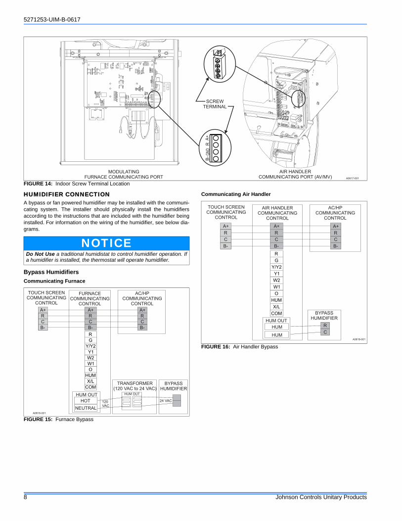
HUMIDIFIER CONNECTIONA bypass or fan powered humidifier may be installed with the communi-cating system. The installer should physically install the humidifiersaccording to the instructions that are included with the humidifier beinginstalled. For information on the wiring of the humidifier, see below dia-grams.
Bypass Humidifiers
Communicating Furnace
Communicating Air Handler
FIGURE 14: Indoor Screw Terminal Location
NOTICEDo Not Use a traditional humidistat to control humidifier operation. Ifa humidifier is installed, the thermostat will operate humidifier.
FIGURE 15: Furnace Bypass
FIGURE 16: Air Handler Bypass
8 Johnson Controls Unitary Products

5271253-UIM-B-0617
Fan Powered Humidifiers
Communicating Furnace
Communicating Air Handler
SECTION V: INITIAL POWER-UP
Before applying power, check to make sure that all wiring has beencompleted as instructed through the installation instructions of theequipment on the system.
Once power is applied, the installer should return to the thermostat tocomplete the installation process.
POWER-UP SEQUENCEThe following screens will load upon initial power up.
SYSTEM CONFIGURATIONAfter selecting the “Next” button, the Touch-Screen Thermostat willbegin a routine to “discover” the system components and identify theIndoor and Outdoor Communicating Equipment.
FIGURE 17: Furnace Fan Powered
WARNINGDo not exceed the recommended 1 amp limit on the 120 VAC Plug orit could cause damaged to the Contactor and Control Board.
FIGURE 18: Air Handler Fan Powered
WARNINGDo not exceed the recommended 1 amp limit on the 120 VAC Plug orit could cause damage to the relay on control board.
!
!
CAUTIONFailure to follow this caution may result in equipment damage.Do not power the system until you have confirmed that the wiring has beencompleted correctly (per this document).
FIGURE 19: Auto Setup
FIGURE 20: ID Search
!
PRESS NEXT TOBEGIN AUTO SETUP
AUTO SETUP
NEXT
A0622-001
SEARCHING FOR CONTROLS...
INDOOR EQUIP TYPE
BACK
A0623-001
Johnson Controls Unitary Products 9

5271253-UIM-B-0617
The installer will be directed through screens that are dependent uponthe system being configured.
Heat kit configuration screens will appear in a communication systemthat includes a communicating variable speed air handler (indicated bya “-C” in the model number).
FIGURE 21: Found Mod Furnace
FIGURE 22: OD Search
FIGURE 23: YGVI
FOUND: MODULATING FURNACE
INDOOR EQUIP TYPE
NEXTBACK
A0624-001
SEARCHING FOR CONTROLS...
OUTDOOR EQUIP TYPE
BACK
A0625-001
FOUND: YGVI
OUTDOOR EQUIP TYPE
NEXTBACK
A0626-001
FIGURE 24: Heat Kit
FIGURE 25: Electric Heat Size - W1 4.2
FIGURE 26: Electric Heat Size - W2 12.5
IMPORTANTIf you have a system which has a heat kit installed, but did not see theheat kit configuration screens, be sure to check the air handler controlto insure that the heat kit jumper is on “Heat”. This only applies to theAV/MV Air Handler.
6HKx6500206
HEAT KIT
DEFAULT NEXTBACK
A0627-001
4.2 KW
ELEC HEAT SIZE - W1
DEFAULT NEXTBACK
A0628-001
12.5 KW
ELEC HEAT SIZE - W2
DEFAULT NEXTBACK
A0629-001
10 Johnson Controls Unitary Products

5271253-UIM-B-0617
They system summary screen will appear in every system install. Thisscreen displays the equipment configuration.
SECTION VI: SERVICE MODEENTERING SERVICE MODETo enter the service portion of the control press and hold (for 5 sec-onds) on the service van located on the settings screen. See Figure 23.
SYSTEM SETTINGSDepending on the equipment that has been installed, the system set-tings screen will display different user options.
NOTICEThe modulating furnace airflow during heating is still controlled by theignition control not the thermostat.
FIGURE 27: Screen Settings
SETTINGS
SVC
72
A0630-001
TABLE 5: Equipment Settings
Variable Default Settings Explanation
Auto Allowed Yes Yes or No This enables or disables the ability of the Auto Mode Feature.
Prog or Non-Prog Prog Prog or Non-Prog Allows the thermostat to run a schedule or not
Fahrenheit or Celsius
°F °F or °CAllows the thermostat temperatures to be displayed in Fahrenheit or Celsius
Smart Recovery Yes Yes or No
Smart recovery is used in programmable mode. The controller initiates equipment operation, if required before the start time of the program schedule day part. This is done to reach the program schedule event's desired temperature setpoint at the time the even occurs, rather than after.
Fan On with W No Yes or NoSupplies a fan output demand as soon as a W1 or W2 output demand is active.
Indoor Temp Offset
0° -5°, -4°, -3°, -2°, -1°, 0°,1°, 2°, 3°, 4°, 5°
Allows the user to calibrate the displayed temperature from the measured temperature in the control
Indoor Hum Offset 0%-5%, -4%, -3%, -2%, -1%, 0%, 1%, 2%, 3%, 4%, 5%
Allows the user to calibrate the displayed humidity from the measured humidity in the control
Auto Changeover 30 MIN5 MIN, 10 MIN, 15 MIN, 20 MIN, 25 MIN, 30 MIN
Sets the minimum time between switching from heat-to-cool from cool-to-heat demands when operating in Auto Mode.
Cool Lockout OFF OFF, 55°, 60°, 65°, 70°, 75°, 80°When enabled, will not allow cooling operation when the outdoor temperature drops below the setting.
Time Between Fuel Types
15 MIN 10 MIN, 15 MIN, 20 MIN, 25 MINSets the minimum time limit between switching from one fuel type to another
Cycles per Hour 4 4 or 6This timer is set to 15 or 10 minutes. This time must elapse from the start of one cycle before another can start.
Humidifier No Yes or NoThe control will only activate the humidifier if there is a demand for both heating and humidity.
Dehumidifier NoNO, OVERCOOL 1°F, OVERCOOL 2°F, OVERCOOL 3°F,
The control will continue to run cooling up to 3 degrees below set point to meet humidity setting of the home
Max Heat Setpoint
88° 50°F to 88°F Choose the maximum heating setpoint that is available.
Min Cool Setpoint 52°F 52°F to 90°F Choose the minimum cooling setpoint that is available
AUX Heat Lock-out
OFFOFF, 5°, 10°, 15°, 20°, 25°, 30°, 35°, 40°, 45°, 50°, 55°
If the auxiliary heat lock out temperature setting is not OFF and the outdoor air temperature is greater than auxiliary heat lock out temperature, then the Aux Heat (W1 & W2) outputs shall not turn on.
Continued on next page.
Johnson Controls Unitary Products 11

5271253-UIM-B-0617
HP Lockout OFFOFF, 5°, 10°, 15°, 20°, 25°, 30°, 35°, 40°, 45°, 50°, 55°
If a setting of OFF is selected, The heating equipment cycleshall always start with the heat pump regardless of the outdoorair temperature. If a lockout temperature is selected and the outdoor air temperature is less than the selected temperature,the heating cycle is started with the AUX Heat source. If theoutdoor air temperature is equal to or greater than the selectedtemperature, the heating cycle is started with the heat pump.
Stage Delay10 MIN (120 MIN for Variable Speed)
2 MIN - 120 MIN (in 1 Minute increments)
The minimum amount of time the current stage must be energized before staging up to the next stage of capacity
Forced Stage Up30 MIN(360 MIN for Variable Speed)
OFF - 360 MIN (in 10 Minute increments)
If time in a current demanded stage reaches the forced stage upselected time, the thermostat will stage up to the next availablestage of capacity (even if differential demand is not met).
Differential 0.5°F0.3°F,0.4°F, 0.5°F, 0.6°F, 0.7°F, 0.8°F, 0.9°F, 1.0°F, 1.1°F, 1.2°F, 1.3°F, 1.4°F, 1.5°F, 1.6°F, 1.7°F, 1.8°F, 1.9°F, 2.0°F
This is the required difference between the current room temperature and the setpoint before demand is initiated. This value is additive fore each additional stage of equipment being demanded.
Air Filter Reminder
3000 HRS OFF to 15,000 HRSDefines a chosen number of hours before a System Event willoccur to remind the homeowner to change the indoor air filter.
UV Lamp Reminder
OFF OFF to 15,000 HRSIf a UV Lamp is installed, this enables a chosennumber of hours before a System Event will occur toremind the homeowner to clean the UV Lamp.
EAC Reminder OFF OFF to 15,000 HRSIf an EAC is installed, this enables a chosen number of hours before a System Event will occur to remind the homeowner to clean the EAC Reminder.
Line Frequency 60 HZ 50 HZ or 60 HZThis is used to increment operation timers within the thermostat to ensure timing accuracy and to allow for preemptive control of a power-out situation for the thermostat.
Brands YorkNone, York, Coleman, Luxaire, Champion, Fraser-Johnson
This will be displayed on the Sleep Screen.
Efficiency Fault Disabled Disabled or EnabledFaults that cause reduced system output but does not stop the equipment from running. Disabled faults will be logged but will not be displayed on the Home Screen Banner.
Warning Fault Disabled Disabled or EnabledDisabled faults will be logged but will not be displayed on the Home Screen Banner.
Status Fault Disabled Disabled or EnabledFault that does not harm or stop equipment operation. Disabled faults will be logged but will not be displayed on the Home Screen Banner.
Defrost Temp 50°F 50°F, 60°F, 70°F, or 80°F The temperature at which defrost is terminated
Comfort/Efficiency Efficiency Comfort or EfficiencyThis is used to determine how quickly the compressor will ramp up to meet setpoint.
Demand Response
DisabledDisabled, Enabled (Open), Enabled (Closed)
This is used to enable or disable the demand response feature.
Demand Resp Action
4°F 4°, 6°, 8°, 10°, Shut Down
When Demand Response is active, the setpoint will update tothe selected temperature value or the equipment will shut down.The setpoint can be raised or lowered when the event is active,but the temperature selection differential must be maintained
Heating Airflow Adjust
0% -10%, -5%, 0%, 5%, 10%Allows the heating airflow CFM to be adjusted by plus/minus 5 or 10%.
Cooling Airflow Adjust
0% -10%, -5%, 0%, 5%, 10%Allows the cooling airflow CFM to be adjusted by plus/minus 5 or 10%.
Climate Normal Normal, Humid, DryThese settings are not implemented in Heat Mode. Selecting aDry climate will increase the current CFM by 10%. Selecting aHumid climate will decrease the current CFM by 10%.
Delay Profiles Normal Normal, Humid, Dry, TemperateThese profiles will run in COOL mode and are not implementedin heating. Each profile is designed to accommodate the original environment where the equipment is installed.
Humidistat Jumper
Yes Yes or NoThis setting will affect COOL Mode only. When the jumper is set to YES and there is a demand for dehumidification then the indoor CFM will be reduced by 15%.
TABLE 5: Equipment Settings
12 Johnson Controls Unitary Products

5271253-UIM-B-0617
FAULTS & SYSTEM EVENTS This screen allows the user to activate whether faults will be displayedon the home screen. Equipment faults will fall into 1 of the following 4categories.
TABLE 6: Float Switch Settings (AHV, AVC, and 2-Stage Variable Speed ECM Furnace)
Variable Default Settings Explanation
Float Switch DisabledEnabled (Open), Enabled (Closed), Disabled
This screen allows the user to activate the optional condensate float switch (S1-ACS2) and to determine how the outdoor equipment will shut down.
TABLE 7: Auxiliary Settings (2-Stage Variable Speed ECM Furnace)
Variable Default Settings Explanation
AUX Switch DisabledEnabled (Open), Enabled (Closed), Disabled
This screen allows the user to activate the optional dry relay contact which is supplied by the utility company.
AUX Switch: Heat Stage Down Stage Down or Shut Off CompThis screen allows the user to determine the equipment functionality when the AUX Switch is activated.
AUX Switch: Cool Stage Down Stage Down or Shut Off CompThis screen allows the user to determine the equipment functionality when the AUX Switch is activated.
FIGURE 28: Screen System Set Faults
EFFICIENCY FAULTS DISABLED
WARNING FAULTS DISABLED
STATUS FAULTS DISABLED
SYSTEM SETTINGS
A0631-001
TABLE 8: Faults
Variable Default Settings Explanation
Critical N/A N/AFaults that stop equipment operation
Efficiency DisableDisable or Enable
Faults that cause reduced system output but does not stop the equipment from running
Warning DisableDisable or Enable
Status DisableDisable or Enable
Fault that does not harm or stop equipment operation.
Johnson Controls Unitary Products 13

5271253-UIM-B-0617
TABLE 9: Critical Faults
CRITICAL Fault (Displayed Text) Description
Thermostat
COMM ERROR OD CTRLThere was no response from the device within 10 seconds of the master’s query after having communicated prior
COMM ERROR ID CTRLThere was no response from the device within 10 seconds of the master’s query after having communicated prior
COMM ERROR BACK PCB Valid packet has not been received from back PCB within last 15 seconds
Air Handler (AHV or AVC)
INDOOR: NO MODEL PLUGID Plug is not present or not connected properly. Check for loose plug or loose wires in plug.
INDOOR: CONTROL FAILURE RECOVERY Control recovered from internal error
INDOOR: CONTROL FAILURE Control Failure
Modulating Furnace
FURNACE: FLAME W/OUT POWERFlame is present with no power being supplied to gas valve. This can be caused by a gas valve that is slow to close or that leaks gas through to the burners
FURNACE: HIGH LIMIT OPENHigh limit switch or 24 volt fuse is open. Can be caused by restricted airflow or open fuse
FURNACE: ROLLOUT OR AUX OPENRollout or auxiliary switch open. Reset rollout switch if possible. Check limit switch in air blower housing
FURNACE GAS VALVE FAILURE Current failure on modulating gas valve
FURNACE: SUPPLY PWR REVERSEDReversed line polarity or improper grounding. Check the polarity of incoming power and grounding. Check transformer.
FURNACE: GAS VALVE CIRCUIT SHORTGas valve circuit shorted. Check gas valve wiring. If correct, replace gas valve
FURNACE: BLOWER FAILURE Main blower failure
FURNACE: NO MODEL PLUGID plug is not present or not connected properly. Check for loose plug or loose wires in plug
FURNACE: JUMPER ERROR Jumper Error
FURNACE: PRESSURE SWITCH OPENStuck open pressure switch indicates that the pressure switch is open when it should be closed
FURNACE: IGNITION FAILEDLockout due to no ignition. Check gas supply, ignitor, gas valve, and flame sensor
FURNACE: MULTI FLAME DROPOUTSLockout due to too many flame recycles. Can be caused by fault gas valve, low gas pressure, or dirty flame sensor
2-Stage Furnace
FURNACE: FLAME W/OUT POWER Flame sensed with gas valve off
FURNACE: LIMIT/ROLLOUT OPEN Limit/Rollout switch open
FURNACE: LIMIT/ROLLOUT OPEN 15 MIN Limit/Rollout switch open more than 15 minutes
FURNACE: PRESSURE SWITCH LOCKOUT Pressure switch cycle lockout
FURNACE: SUPPLY PWR REVERSED Incorrect line voltage polarity
FURNACE: GAS VALVE CIRCUIT SHORT Gas valve circuit shorted
FURNACE: LIMIT/ROLLOUT OPEN 5 MIN Limit/Rollout switch open from 5 to 15 minutes
FURNACE: NO MODEL PLUG ID Plug missing or not connected properly
FURNACE: CONTROL FAILURE Control Failure
FURNACE: PRESSURE SWITCH OPEN Pressure switch open with inducer on
FURNACE: IGNITION FAILED Lockout due to failed ignition
FURNACE: MULTI FLAME DROPOUTS Lockout due to too many flame dropouts
Indoor AUX
INDOOR: CONTROL FAUILURE Control Failure
INDOOR: LOW VOLTAGE (<16VAC) Low voltage (below 16 VAC) stopped current relay outputs
INDOOR:X/L INPUT – FLASH 2 X/L Input Status
INDOOR:X/L INPUT – FLASH 4 X/L Input Status
Outdoor AUX
OUTDOOR:HPS LOCKOUT System in high pressure switch lockout
OUTDOOR:CONTROL FAILURE Control Failure
OUTDOOR:LPS LOCKOUT System in low pressure switch lockout
OUTDOOR:LOW VOLTAGE(< 16VAC) Low voltage (below 16.0 VAC) stopped current relay outputs
OUTDOOR:COMPRESSOR MISWIRE Compressor contactor miswire
Continued on next page.
14 Johnson Controls Unitary Products

5271253-UIM-B-0617
YGVI
OUTDOOR:HPS LOCKOUT-HP High Pressure Switch fault. Last mode of operation was heat pump.
OUTDOOR:HPS LOCKOUT-DEFROST High Pressure Switch fault. Last mode of operation was defrost.
OUTDOOR:CONTROL FAILURE Control Failure
OUTDOOR:LPS LOCKOUT Low Pressure Switch Lockout
OUTDOOR:LOW VOLTAGE(< 16VAC) Low voltage (below 16.0 VAC) stopped current relay outputs
OUTDOOR:AMBIENT SENSOR SHORTED Outdoor ambient temperature sensor failure (shorted)
OUTDOOR:AMBIENT SENSOR OPEN Outdoor ambient temperature sensor failure (open)
OUTDOOR:LIQUID LINE SENSOR SHORT Liquid line sensor failure (shorted)
OUTDOOR:LIQUID LINE SENSOR OPEN Liquid line sensor failure (open)
OUTDOOR:HIGH DISCHARGE TEMP - SOFT LOCKOUT High discharge line temperature
OUTDOOR:LOW DISCHARGE TEMP - SOFT LOCKOUT Low discharge line temperature
OUTDOOR:HIGH DISCHARGE TEMP - HARD LOCKOUT High discharge line temperature
OUTDOOR:LOW DISCHARGE TEMP - HARD LOCKOUT Low discharge line temperature
OUTDOOR:DISCHARGE LINE SENSOR SHORT Discharge line sensor failure (shorted)
OUTDOOR:BONNET SENSOR SHORT Bonnet sensor failure (shorted)
OUTDOOR:FOSSIL FUEL CONFIG ERRORFossil Fuel Mode setting error. FFUEL jumper in the OFF position with bonnet sensor present
OUTDOOR:COMPRESSOR MISWIRE Compressor contactor miswire
OUTDOOR:Y2 W/O Y1-SOFT LOCKOUT Y2 present without Y1
OUTDOOR:NO DEFROST CURVE SELECTED Defrost Curve Jumper Error. Invalid jumper setting preventing compressor operation.
VS Outdoor Control
OUTDOOR:CONTROL FAILURE Control Failure
OUTDOOR:HPS SOFT LOCKOUT-NORMAL High pressure switch lockout. Last mode of operation was normal compressor.
OUTDOOR:HPS HARD LOCKOUT-NORMAL High pressure switch lockout. Last mode of operation was normal compressor.
OUTDOOR:HPS SOFT LOCKOUT-DEFROST High pressure switch lockout. Last mode of operation was defrost.
OUTDOOR:HPS HARD LOCKOUT-DEFROST High pressure switch lockout. Last mode of operation was defrost.
OUTDOOR:LOW VOLTAGE(< 19VAC) Low Voltage (<19 VAC) stopped current relay outputs for > 2 seconds
OUTDOOR:COMM LOST INVERTER DRIVE Inverter Control Communications Fault
OUTDOOR: COMM LOST- SYSTEM MASTER RS-485 Communications Lost
OUTDOOR:AMBIENT SENSOR SHORTED Outdoor ambient sensor failure (short)
OUTDOOR:AMBIENT SENSOR OPEN Outdoor ambient sensor failure (open)
OUTDOOR:COIL TEMP SENSOR SHORTED Coil sensor failure (short)
OUTDOOR:COIL TEMP SENSOR SHORTED-SOFT LOCKOUT Coil sensor failure (short)
OUTDOOR:COIL TEMP SENSOR OPEN Coil sensor failure (open)
OUTDOOR:COIL TEMP SENSOR OPEN-SOFT LOCKOUT Coil sensor failure (open)
OUTDOOR:LIQUID TEMP SENSOR SHORTED Liquid line temperature sensor failure (short)
OUTDOOR:LIQUID TEMP SENSOR SHORTED-SOFT LOCKOUT Liquid line temperature sensor failure (short)
OUTDOOR:LIQUID TEMP SENSOR OPEN Liquid line temperature sensor failure (open)
OUTDOOR:LIQUID TEMP SENSOR OPEN-SOFT LOCKOUT Liquid line temperature sensor failure (open)
OUTDOOR:DISCHARGE TEMP SENSOR SHORTED Discharge temperature sensor failure (short)
OUTDOOR:DISCHARGE TEMP SENSOR OPEN Discharge temperature sensor failure (open)
OUTDOOR:DISCHARGE TEMP SENSOR OPEN-SOFT LOCKOUT Discharge temperature sensor failure (open)
OUTDOOR:SUCTION TEMP SENSOR SHORTED Suction temperature sensor failure (short)
OUTDOOR:SUCTION TEMP SENSOR SHORTED-SOFT LOCKOUT Suction temperature sensor failure (short)
OUTDOOR:SUCTION TEMP SENSOR OPEN Suction temperature sensor failure (open)
OUTDOOR:SUCTION TEMP SENSOR OPEN-SOFT LOCKOUT Suction temperature sensor failure (open)
OUTDOOR:DISCHARGE PRESSURE SENSOR LOW VOLTAGE Discharge pressure sensor failure (low voltage)
OUTDOOR:DISCHARGE PRESSURE SENSOR LOW VOLTAGE-SOFT LOCKOUT
Discharge pressure sensor failure (low voltage)
OUTDOOR:DISCHARGE PRESSURE SENSOR HIGH VOLTAGE Discharge pressure sensor failure (high voltage)
OUTDOOR:DISCHARGE PRESSURE SENSOR HIGH VOLTAGE-SOFT LOCKOUT
Discharge pressure sensor failure (high voltage)
OUTDOOR:SUCTION PRESSURE SENSOR LOW VOLTAGE-SOFT LOCKOUT
Suction pressure sensor failure (low voltage)
Continued on next page.
TABLE 9: Critical Faults
CRITICAL Fault (Displayed Text) Description
Johnson Controls Unitary Products 15

5271253-UIM-B-0617
OUTDOOR:SUCTION PRESSURE SENSOR HIGH VOLTAGE-SOFT LOCKOUT
Suction pressure sensor failure (high voltage)
OUTDOOR:HIGH DISCHARGE TEMP High discharge temperature
OUTDOOR:HIGH DISCHARGE TEMP - SOFT LOCKOUT High discharge temperature
OUTDOOR:HIGH DISCHARGE TEMP - HARD LOCKOUT High discharge temperature
OUTDOOR:LOW SUCTION PRESSURE Low suction pressure
OUTDOOR:LOW SUCTION PRESSURE - SOFT LOCKOUT Low suction pressure
OUTDOOR:LOW SUCTION PRESSURE - HARD LOCKOUT Low suction pressure
OUTDOOR: MULTIPLE INVERTER FAULTS-SOFT LOCKOUT Multiple Inverter Faults
VS Inverter Control
INVERTER:COMPRESSOR PHASE OVER CURRENT Compressor Phase Over Current
INVERTER:AC INPUT OVER CURRENT AC Input Over Current
INVERTER:DC BUS OVER VOLTAGE DC Bus Over Voltage
INVERTER:DC BUS UNDER VOLTAGE DC Bus Under Voltage
INVERTER:AC INPUT OVER VOLTAGE AC Input Over Voltage
INVERTER:AC INPUT UNDER VOLTAGE AC Input Under Voltage
INVERTER:POWER MODULE OVER TEMP Power Module Over Temp
INVERTER:PFC-IGBT OVER TEMP PFC-IGBT Over Temp
INVERTER:LOST ROTOR POSITION Lost Rotor Position
INVERTER:COMPRESSOR PHASE CURRENT IMBALANCE Compressor Phase Current Imbalance
INVERTER:MICROELECTRONIC FAULT Microelectronic Fault
INVERTER:POWER MODULE TEMP LOW/SENSOR OPEN Power Module Temp Low or Sensor Open Fault
INVERTER:COMM ERROR Modbus Communication Lost
INVERTER:PFC MCU & DSP COMM ERROR PFC MCU and DSP Communication Lost
INVERTER:COM MCU & DSP COMM ERROR COM MCU and DSP Communication Lost
INVERTER:PFC-IGBT LOW TEMP/SENSOR OPEN PFC-IGBT Temp Low or Sensor Open Fault
INVERTER:COMPRESSOR MODEL CONFIG ERROR Compressor Model Configuration Error
INVERTER:HPS CONFIG ERROR High Pressure Sensor Type Configuration Error
INVERTER: DLT CONFIG ERROR DLT Sensor Configuration Error
INVERTER:FAULT LIMIT LOCKOUT Fault Limit Lockout
TABLE 9: Critical Faults
CRITICAL Fault (Displayed Text) Description
16 Johnson Controls Unitary Products

5271253-UIM-B-0617
TABLE 10: Efficiency Fault
EFFICIENCY Fault (Displayed Text) Description
Thermostat
ID TEMP SENSOR HIGH Temperature reading > 122 F
ID TEMP SENSOR LOW Temperature reading = 0 or reading not available
REMOTE SENSOR HIGHRemote temperature > 122 F. Only flagged if remote sensor set to use as indoor temperature (REMOTE SENSOR setting se to INDOOR or AVERAGE
REMOTE SENSOR LOWRemote temperature = 0. Only flagged if remote sensor set to use as indoor temperature (REMOTE SENSOR setting se to INDOOR or AVERAGE
HUM TEMP SENSOR HIGHHumidity sensor temperature > 122 F. Only flagged if using hum temperature as a backup source during a fault condition with the primary temperature sensor
HUM TEMP SENSOR LOWHumidity sensor temperature = 0. Only flagged if using hum temperature as a backup source during a fault condition with the primary temperature sensor
ID TEMP RANGE HIGH Indoor temperature is > 99.0 F
ID TEMP RANGE LOW Indoor temperature is < 40.0 F
HUM SENSOR FAILURE Humidity sensor timed out. Humidity reading is > 99% or Humidity reading is 0
HUMIDITY RANGE HIGH Humidity reading is > 90%
HUMIDITY RANGE LOW Humidity reading is < 10%
OUTDOOR SENSOR FAILURE OD temp > 127 or < -60
Modulating Furnace
FURNACE: PRESSURE SWITCH CLOSEDPressure switch closed with inducer pressure below pressure switch setpoint (switch is closed when it should be open). Check pressure switch.
FURNACE: SOFT LIMIT WARNING Soft limit warning
FURNACE: AIR BLOCKAGE WARNING Air blockage warning
FURNACE: UNKNOWN FAILURE Unknown failure
FURNACE: FLAME ROD AGE WARNING Flame rod age warning
2-Stage Furnace
FURNACE: PRESSURE SWITCH CLOSED Pressure switch closed with inducer off
FURNACE: 2S PRESSURE SWITCH OPEN 2nd stage pressure switch open with high inducer on
FURNACE: FLAME ROD AGE WARNING Flame rod warning
Outdoor AUX
OUTDOOR:Y2 W/O Y1-SOFT LOCKOUT Y2 present without Y1
OUTDOOR:HPS OPEN W/O COMPRESSOR HPS open with no call for compressor
YGVI
OUTDOOR:PIPE FREEZE TIMER EXPIRED Pipe Freeze Protection Timer expiration
OUTDOOR:HPS OPEN W/O COMPRESSOR HPS open with no call for compressor
VS Control
OUTDOOR:HPS OPEN High-pressure switch fault (not in lockout yet)
OUTDOOR:PIPE FREEZE TIMER EXPIRED Pipe Freeze Timer expiration
OUTDOOR:REPAIR MODE HEAT-HP Conventional Y1 signal receive in HP mode
OUTDOOR:REPAIR MODE COOL-HP” Conventional Y1 and O signals receive in HP mode
OUTDOOR:REPAIR MODE COOL-AC Conventional Y1 signal receive in AC mode
OUTDOOR:HIGH SUPERHEAT” High Superheat
OUTDOOR:LOW SUPERHEAT Low Superheat
OUTDOOR:HIGH SUBCOOL High Subcool
OUTDOOR:LOW SUBCOOL Low Subcool
VS Inverter
INVERTER:COMPRESSOR PHASE CURRENT FOLDBACK
Compressor Phase Current Foldback Timeout
INVERTER:AC INPUT CURRENT FOLDBACK
AC Input Current Foldback Timeout
INVERTER:POWER MODULE HIGH TEMP Power Module Temp High
INVERTER:PFC-IGBT HIGH TEMP PFC-IGBT High Temp
INVERTER:POWER MODULE TEMP FOLDBACK
Power Module Temp. Foldback Timeout
Johnson Controls Unitary Products 17

5271253-UIM-B-0617
TABLE 11: Warning Fault
WARNING Fault (Displayed Text) Description
Indoor AUX
OUTDOOR:LOW VOLTAGE(< 19VAC) Low voltage (below 19.2 VAC) preventing further relay outputs
Outdoor AUX
OUTDOOR:LOW VOLTAGE(< 19VAC) Low voltage (below 19.2 VAC) preventing further relay outputs
OUTDOOR:AMBIENT SENSOR SHORTED Outdoor ambient temperature sensor failure (shorted)
OUTDOOR:AMBIENT SENSOR OPEN Outdoor ambient temperature sensor failure (open)
YGVI
OUTDOOR:LOW VOLTAGE(< 19VAC) Low voltage (below 19.2 VAC) preventing further relay outputs
OUTDOOR:O INPUT-AC MODE O signal received in AC Mode
OUTDOOR:W INPUT-AC MODE W signal received in AC Mode
OUTDOOR:W & O INPUTS-AC MODE W and O signals received in AC Mode
OUTDOOR:W & O INPUTS-HP MODE W and O signals received in HP Mode
VS Control
OUTDOOR:LOW VOLTAGE(< 22VAC) Low Voltage (< 22.2VAC) preventing further relay outputs for > 2 seconds
OUTDOOR:O INPUT-AC MODE O signal received in AC mode
OUTDOOR:W & O INPUTS-AC MODE W and O signal received in AC mode
OUTDOOR:W & O INPUTS-HP MODE W and O signal received in HP mode
OUTDOOR: LOW SUCTION PRESSURE Low suction pressure
OUTDOOR: LOW DISCHARGE TEMP Low discharge temperature
OUTDOOR: LOW SYSTEM CHARGE Low system charge
OUTDOOR: HIGH SYSTEM CHARGE High system charge
TABLE 12: Status Fault
STATUS Fault (Displayed Text) Description
Thermostat
NOT CONNECTED TO SERVER Not connected to Ayla server
NOT CONNECTED TO ROUTER Router signal strength is 0 bars (not connected)
WIFI HARDWARE FAULT Communications error occurred with Wi-Fi module (resets after valid message received)
Indoor AUX
INDOOR:X/L INPUT-FLASH 1 X/L Input Status
INDOOR:X/L INPUT-FLASH 4 X/L Input Status
INDOOR:X/L INPUT-FLASH 5 X/L Input Status
INDOOR:X/L INPUT-FLASH 6 X/L Input Status
INDOOR:X/L INPUT-FLASH 7 X/L Input Status
INDOOR:X/L INPUT-FLASH 8 X/L Input Status
INDOOR:X/L INPUT-FLASH 9 X/L Input Status
INDOOR:X/L INPUT-CONSTANT X/L Input Status
2-Stage Furnace
FURNACE: Y WITHOUT G Y thermostat demand without a G
VS Control
OUTDOOR:DEMAND RESPONSE Demand Response
ID EEV
ID EEV: INVALID PRESSURE TRANS-DUCER
Invalid pressure transducer
ID EEV: INVALID SUCTION TEMP Invalid suction temperature
ID EEV: FULLY OPEN IN SUPERHEAT Valve position to fully open while in superheat control mode
ID EEV: SUCTION PRESSURE OUT OF RANGE
Suction pressure out of range
ID EEV: COMMUNICATIONS LOST RS-485 Communication not sensed
18 Johnson Controls Unitary Products

5271253-UIM-B-0617
Ventilation SettingsThe Ventilation Settings screens are used to view/edit settings associated with a whole home ventilator (ERV/HRV) devices. These screens are onlyaccessible in system which have an ERV/HRV Accessory control installed. The settings available are explained in the table below.
There are additional settings for ventilation. These settings will deter-mine if the ventilator is opened during a call for conditioning. The ther-mostat will open ventilation any time there is a call for conditioning if theoutdoor temperature falls in the “Ventilation with a heating/cooling call”.Otherwise ventilation will run with the indoor blower per the previouslydescribed settings.
Finally the ventilation can be controlled per indoor humidity. If the out-door temperature is above 50 degrees the touch screen can be set sothat it will disable ventilation if the indoor humidity rises above thedesired setting.
TABLE 13: System Events
System Events: Logged but NOT shown in banner
Event (Displayed Text) Description
SETUP CORRECTION Setting was adjusted b/w it was out of range or issue w/ other related setting
OTA PASS (APPF) OTA software update for front PCB application successful
OTA PASS (APPB) OTA software update for back PCB application successful
OTA PASS (BOOT) OTA software update for bootloader application successful
OTA TIMED OUT OTA software updated has timed out after 3 (15 minute) attempts
FRONT BOARD CHANGED Front PCB has been changed with a new unconfigured front PCB
AIR FILTER RESET Air Filter # hours remaining has been reset (from FILTER screen)
HUMIDIFIER FILTER RESET Humidifier Filter # hours remaining has been reset (from FILTER screen)
UV LAMP RESET UV Lamp # hours remaining has been reset (from FILTER screen)
EAC RESET EAC # hours remaining has been reset (from FILTER screen)
STARTUP Flagged at startup to indicate that thermostat has been reset
NFC EVENT SUCCESS Successful NFC Read/Write has occurred
LOG CLEARED Faults and events have been reset from the Log
System Events: Logged and displayed in banner while condition exists
AIR FILTER REMINDER Air filter change reminder is active (run hours have expired)
HUMIDIFIER FILTER REMINDER Humidifier filter change reminder is active (run hours have expired)
UV LAMP REMINDER UV Lamp change reminder is active (run hours have expired)
EAC REMINDER EAC change reminder is active (run hours have expired)
TABLE 14: Ventilation Settings
Variable Default Settings Explanation
Ventilation Mode Timed Continuous, Timed or Off This will determine how often the ventilation device will be opened
Ventilation Runtime per Cycle 20 min. 5-55 min in 5 min intervalsIf ventilation mode is set to “Timed”, the control will allow ventilationper this setting per Ventilation Cycle Time
Ventilation Cycle Time 1 hour 1 -4 hoursIf ventilation mode is set to “Timed”, the control will allowVentilation Runtime per this setting
Ventilation Limits Disabled Disabled, Default, and Manual If there is a damper installed for ventilation purposes
No Ventilation Above 100 FThe touch screen will not allow ventilation if the outdoortemperature exceeds this setting
No Ventilation Below 0 FThe touch screen will not allow ventilation if the outdoortemperatures is below this setting
FIGURE 29: Vent with Heat
VENT WITH HEAT 10°F
VENT WITH COOL 85°F
NO VENT ABOVE HUM 50%
SYSTEM SETTINGS
A0632-001
Johnson Controls Unitary Products 19

SECTION VII: SERVICE SETTINGSAdditional service information such as event/fault logs and dealer con-tent can be found by going to the homeowner settings screen.
LOGHere the event and fault log screen can be viewed. Pressingan entry displayed on the “Log” screen will prompt a screenthat tells when the event or fault last occurred and how manytimes it has occurred.
Press the “Reset Log” to delete all the displayed log entries.
DEALER INFORMATIONThe information displayed on this screen is editable via theThermostat 280 app.
FORCED OPERATIONPressing and holding TIMERS text for 5 seconds will cleartimer countdown values for ON timer, OFF timer, CYCLEtimer and STAGE DELAY timer. Current lockouts will beactively displayed in this screen. Pressing and holding LOCK-
OUT TIMERS text for 5 seconds will clear timer values for COOL timer,AUX HEAT timer and HP HEAT timer
FIGURE 30: Log
FIGURE 31: Screen Log Startup
STARTUP
-EMPTY-
-EMPTY-
LOG
A0633-001
3/31/15 11:14AMCONTROL: SYSTEMCOUNT: 2
LOG
A0634-001
FIGURE 32: Screen Service
FIGURE 33: Status
SVC
Joe’s Plumbing HVAC(555) [email protected]
SERVICE
A0635-001
ONOFFCYCLESTAGE DELAYFORCED STAGE UPAUTO CHANGEFUEL TYPE CHANGE
0000169500
STATUSTIMERS (SECONDS):
A0636-001
Subject to change without notice. Published in U.S.A. 5271253-UIM-B-0617Copyright © 2017 by Johnson Controls, Inc. All rights reserved. Supersedes: 5271253-UIM-A-1016
York International Corp.5005 York Drive
Norman, OK 73069