installation manual - hainbuch · segmented mandrel t212 – general 1.3 explanation of symbols...
TRANSCRIPT

Installation manual
Clamping device
Segmented mandrel T212 RD MANDO SE MAXXOS

Segmented mandrel T212
Table of contents
1 General....................................................................................................................51.1 Information about this manual........................................................................51.2 Description of variants....................................................................................51.3 Explanation of symbols..................................................................................61.4 Limitations of liability.......................................................................................61.5 Max. RPM.......................................................................................................71.6 Copyright........................................................................................................81.7 Scope of delivery............................................................................................81.8 Warranty terms...............................................................................................8
2 Safety......................................................................................................................92.1 Responsibility of the customer.......................................................................92.2 Personnel requirements...............................................................................102.3 Intended use.................................................................................................112.4 Personal protective equipment.....................................................................122.5 Special dangers............................................................................................132.6 Further warnings...........................................................................................162.7 Clamping force.............................................................................................172.8 Screws..........................................................................................................182.9 Functionality.................................................................................................192.10 Environmental protection..............................................................................19
3 Technical data.......................................................................................................203.1 General information......................................................................................203.2 Operating conditions.....................................................................................203.3 Power specifications.....................................................................................213.4 Check............................................................................................................213.5 Dimensional sheet........................................................................................213.6 Type designation..........................................................................................21
4 Structure and function...........................................................................................224.1 Overview RD................................................................................................224.2 Overview SE.................................................................................................234.3 Brief description............................................................................................234.4 Optional Accessories....................................................................................23
4.4.1 Work piece end-stop..........................................................................244.4.2 Segmented clamping bushing............................................................244.4.3 Grease................................................................................................24
5 Transporting, packaging and storing....................................................................255.1 Safety instructions for transporting...............................................................255.2 Symbols on the packaging...........................................................................255.3 Transport inspection.....................................................................................265.4 Unpacking and inner-company transportation.............................................265.5 Packaging.....................................................................................................275.6 Storing..........................................................................................................28
2 Order Hotline +49 7144.907-333
Segmented mandrel T212
6 Assembly...............................................................................................................296.1 Pre-consideration.........................................................................................296.2 Preparations.................................................................................................306.3 Assembly......................................................................................................31
6.3.1 Assembling the draw tube adapter....................................................336.3.2 Assembling the flange........................................................................346.3.3 Assembly of the segmented mandrel [HSK]......................................366.3.4 Assembly of the segmented mandrel [machine spindle]...................386.3.5 Assembly of the segmented mandrel [capteX B]...............................416.3.6 Assembly of the segmented mandrel [quick change-over interface].436.3.7 Checking and adjusting the face run and the concentricity [RD].......436.3.8 Checking and adjusting the face run and the concentricity [SE].......446.3.9 Installation of the hydraulic segmented mandrel...............................456.3.10Assembly of the segmented clamping bushing RD...........................476.3.11Assembly of the segmented clamping bushing SE............................476.3.12Assembling of the work piece end-stop.............................................48
6.4 Work piece....................................................................................................506.5 Inspections...................................................................................................516.6 Control of the stroke position........................................................................526.7 Activities after production is concluded........................................................52
7 Disassembly..........................................................................................................537.1 Safety............................................................................................................537.2 Disassembling the clamping device.............................................................55
7.2.1 Disassembling the work piece end-stop............................................557.2.2 Disassembling the segmented clamping bushing [RD/SE]...............557.2.3 Disassembling the segmented mandrel [HSK]..................................567.2.4 Disassembling the segmented mandrel [machine spindle]...............567.2.5 Disassembling the segmented mandrel [capteX B]...........................577.2.6 Disassembly of the segmented mandrel [quick-change interface]....587.2.7 Disassembly of the hydraulic mandrel...............................................587.2.8 Disassembling the flange...................................................................587.2.9 Disassembling the draw tube adapter................................................59
7.3 Subsequent storage of the clamping device................................................597.4 Disposal........................................................................................................60
8 Maintenance..........................................................................................................618.1 General.........................................................................................................618.2 Cleaning........................................................................................................628.3 Preservation.................................................................................................638.4 Use of lubricant.............................................................................................648.5 Maintenance schedule.................................................................................658.6 Bolt torque....................................................................................................67
9 Trouble shooting...................................................................................................689.1 Safety............................................................................................................689.2 Trouble shooting table..................................................................................699.3 Start-up after corrected fault.........................................................................70
Order Hotline +49 7144.907-333 3

Segmented mandrel T212
10 Appendix...............................................................................................................7110.1 Service Hotline.............................................................................................7110.2 Representatives............................................................................................71
10.2.1Europe................................................................................................7110.2.2America..............................................................................................7410.2.3Asia....................................................................................................7410.2.4Australia.............................................................................................7510.2.5Africa..................................................................................................75
Index..............................................................................................................................77
EC Declaration of conformity.........................................................................................79
»Translation of original installation manual«
4 Order Hotline +49 7144.907-333

Segmented mandrel T212 – General
1 General
1.1 Information about this manual
This manual enables safe and efficient handling of the clamping device.
The manual is a component of the clamping device andmust be kept in the immediate vicinity of the clamping device where it is accessible for personnel at all times. Personnel must have carefully read and understood this manual prior to starting all tasks. The basic prereq-uisite for safe work is compliance with all the safety in-structions and handling instructions in this manual.
Illustrations in this manual are provided for a basic un-derstanding and may deviate from the actual model of the clamping device.
It is assumed that the reader is familiar with standard procedures, such as cleaning the mounting surfaces.
1.2 Description of variants
Two variants of the SPANNTOP nova clamping de-vice are presented in this manual:
Segmented mandrel type 212 RD Segmented mandrel type 212 SE – MAXXOS
If the variants differ in structure, installation, disas-sembling and maintenance or fault correction, theywill be described separately.Based on the headers, sections and action steps canalways be assigned to a specific variant.Starting with weight more than 15 kg, eye bolts mustbe used to transport the clamping device.Usual approaches like a cleaning of the areas forscrewing are presupposed to be familiar
Order Hotline +49 7144.907-333 5

Segmented mandrel T212 – General
1.3 Explanation of symbols
Safety instructions Safety instructions are indicated by symbols in thisoperating manual. The safety instructions are intro-duced by signal words that express the scope of thehazard.The safety instructions must be strictly adhered to.You must act prudently to prevent accidents, personalinjury, and material damage.
DANGER
… indicates an imminent dangerous situationthan can result in death or serious injury if it isnot avoided.
WARNING
… indicates a possible dangerous situationthat can result in death or serious injury if it isnot avoided.
CAUTION
… indicates a possible dangerous situationthat can result in minor or light injury if it es notavoided.
NOTE
… indicates a possible dangerous situationthat can result in material damage if it is notavoided.
Tips and recommen-dations
… indicates useful tips and recommendations,as well as information for efficient and trou-ble-free operation.
1.4 Limitations of liability
All information and instructions in this operating manualhave been provided under due consideration of appli-cable standards and regulations, the current state of technology, as well as our many years of experience.
The manufacturer assumes no liability for damage due to:
Failure to follow the instructions in the manual Non-intended use Deployment of untrained personnel Unauthorized conversions
6 Order Hotline +49 7144.907-333

Segmented mandrel T212 – General
Technical changes Use of non-approved spare parts
The actual scope of delivery can vary from the expla-nations and graphic representations provided in this manual in the case of special versions, if supplemental order options are desired, or on the basis of the latest technical changes.
The agreed obligations in the delivery contract, the general terms and conditions, as well as delivery condi-tions of the manufacturer, and the statutory regulations valid at the time the contract was concluded, apply.
CAUTION!
Our clamping devices are balanced with bal-ance quality G = 4, in one level n = 1.The data on the rotation balance refers to rota-tionally symmetrical work pieces. The clamping of not rotationally symmetricalwork pieces may not be clamped and/or onlybe clamped after consultation with the manu-facturer.Balancing bolts and balancing weights at theclamping devices may not be removed / disas-sembled!
1.5 Max. RPM
CAUTION!
The maximum permissible speed is marked onthe product.By the combination of a clamping device andan add on clamping element a reduction of themaximum permissible speed may be neces-sary. Of all RPMs of the groups specified, the low-
est given RPM must always be used.Note that the clamping force is influenced bythe centrifugal force of the clamping elements. If necessary, adjust the machining force!
Order Hotline +49 7144.907-333 7
Segmented mandrel T212 – General
1.6 Copyright
This manual is protected by copyright and is provided exclusively for internal purposes.
Delivery of the operating manual to third parties, dupli-cation in any form – including excerpts – as well as ex-ploitation and/or communication of the content, are not permitted [except for internal use] without written ap-proval from the manufacturer.
Actions to the contrary make damage compensation mandatory. We reserve the right to enforce additional claims.
1.7 Scope of delivery
All tools and accessories that are not includedin the scope of delivery are marked as option-al.
In scope of delivery of the clamping device: 1 segmented mandrel 1 coupling
Optionally the scope of delivery of the clamping de-vice includes: Spindle flange Trimming sleeve for SAD segmented clamping
bushing Segmented clamping bushing Work piece end-stop Eye bolts
1.8 Warranty terms
The warranty terms are included in the manufacturer's terms and conditions.
8 Order Hotline +49 7144.907-333

Segmented mandrel T212 – Safety
2 Safety
This section provides an overview o fall the importantsafety aspects for optimal protection of personnel, aswell as for safe and trouble-free operation.
2.1 Responsibility of the customer
The device is used in industrial applications. Conse-quently the owner of the device is subject to legal in-dustrial safety obligations.In addition to the safety instruction in this manual,generally valid safety and accident protection guide-lines, and environmental protection guidelines as wellas the machines' manual must be adhered to andcomplied with for the area of implementation of thedevice.
Note in particular that the status scans of the machinemust be adjusted to the respective clamping device.
DANGER!
Risk of injury due to thrown out parts!
Incorrect machine settings may lead to thethrowing out of parts. The status scans the machine must be set to
the respective clamping device. Regularly check the status scans of the ma-
chine, see chapter »Maintenance Schedule«.If the end position can not be reached the jaw module may no longer be used.
Observe the operating instructions of the ma-chine.
WARNING!
Risk of injury!
Declining operating force, for example by de-clining energy supply, may cause serious per-sonal injury. The product may be used only on machines
where it is ensured, that during use, the oper-ating force does not drop.
Order Hotline +49 7144.907-333 9

Segmented mandrel T212 – Safety
WARNING!
Risk of injury!
An incorrect media supply [hydraulic, pneumat-ic], e.g. by damaged or missing seals or pipes,can cause serious personal injury. Hydraulic and / or pneumatic tubes must be
secured by the machine by check valves anda permanent pressure monitoring!
2.2 Personnel requirements
WARNING!
Danger of injury due to insufficient qualifi-cation!
Improper handling of the clamping device cancause serious injury or material damage. Only have activities performed by personnel
who are qualified to perform these activities.
The following qualifications are cited in the operatingmanual for the various activity areas.
Specialized personnelare personnel who due to their specialized training, skills, and experience, as well as knowledge of the applicable regulations, are capable of executing the tasks assigned to them and of recognizing and avoiding possible hazards on their own.
Hydraulic specialistThe hydraulic specialist has been trained for the particular task area in which he is active and is fa-miliar with the relevant standards and regulations. Due to his specialized training and experience the hydraulic specialist can perform tasks on hydraulic equipment and recognize and avoid possible dan-gers on his own.
Electric specialistThe electric specialist has been trained for the par-ticular task area in which he is active and is familiar with the relevant standards and regulations.Due to his specialized training and experience the electric specialist can perform tasks on electric equipment and recognize and avoid possible dan-gers on his own.
Only persons from whom it can be expected that theyreliably execute their work are considered as person-
10 Order Hotline +49 7144.907-333
Segmented mandrel T212 – Safety
nel. Persons whose capability to react is impaired, forinstance through drugs, alcohol, or medication, arenot approved.
Comply with age-specific and job-specific regula-tions that are applicable at the installation site when selecting personnel.
2.3 Intended use
The clamping device is designed for installation in amachine tool according to CE compliant. Within themachine tool the clamping device is designed exclu-sively as a through-bore chuck for bar work and / oras an end-stop chuck for chuck work.The clamping device should only be mounted, operat-ed, maintained, and cleaned by instructed, special-ized personnel.
Intended use also includes compliance with all the in-structions in this manual.
The clamping device is to be used for the case of ap-plication contractually agreed between theproducer/deliverer and the user, as well as such cas-es of application described in the product descriptionwhich are also in accordance with the technical val-ues.
The safe function of the clamping device is, as far asit can be foreseen, guaranteed when it is used for theintended purpose in accordance with the appropriatesafety regulations.
Any use that extends beyond the intended use, or anyother use of the clamping device is considered to bemisuse and can cause dangerous situations.
WARNING!
Danger due to misuse!
Misuse of the clamping device can cause dan-gerous situations.Particularly refrain from the following uses ofthe clamping device: Use in machines other than machine tools. Use in machine tools with technical data oth-
er than that specified on the clamping device.
Claims of any type due to damage arising from non-intended use are excluded.
Order Hotline +49 7144.907-333 11
Segmented mandrel T212 – Safety
Unintended and improper use of the Power Chuck isfor example If workpieces are not clamped properly
If safety regulations are disregarded and persons are working at the clamping device without addition-al protective devices e.g. for machining.
If the clamping device is used for machines or tools for which it is not intended.
2.4 Personal protective equipment
Wearing of personal protective equipment is requiredto minimize health hazards when working with the de-vice. Always wear the protective equipment necessary for
the respective task when working with the device. Follow the instructions that have been posted in the
work area.
Always wear For all tasks always wear:
Protective work clothing
is tight-fitting work clothing with low resistance to tear-ing, with tight sleeves, and without projecting parts. Itis primarily used to protect against entanglement bymoving machine parts. Do not wear rings, chains, or other jewelry.
Safety footwear
for protection against heavy falling parts and slippingon slippery substrates.
For special tasks wear
Special protective equipment is required when exe-cuting special tasks. Separate reference is made tothis equipment in the specific sections of this manual.This special protective equipment is explained below:
Hard hat
to protect against falling and flying parts and materi-als.
12 Order Hotline +49 7144.907-333

Segmented mandrel T212 – Safety
Protective goggles
to protect eyes from flying parts and liquid splashes.
Protective gloves
to protect hands from friction, abrasion, puncturewounds, or deeper injuries, as well as from contactwith hot surfaces.
2.5 Special dangers
In the following section residual risks are cited thatoccur due to installation of the clamping device in amachine tool. In each case the residual risks thathave been determined based on a risk analysis of themachine must be specified by the customer.
Follow the safety instructions listed here and the warnings in the other sections of this manual to re-duce health hazards and to avoid dangerous situa-tions.
Horizontal / lying parts
WARNING!
Danger of injury due to horizontal parts!
Before transporting the clamping device in hor-izontal condition: Put the clamping device on a non-slip pad Screw in the eye bolts
Order Hotline +49 7144.907-333 13

Segmented mandrel T212 – Safety
Suspended loads WARNING!
Life-threatening danger due to suspended loads!
Some clamping devices must be lifted with acrane. When lifting the clamping device thereis a life-threatening hazard due to falling partsor parts swinging out of control. Never step under suspended loads. Comply with the instructions concerning the
intended attachment points. Ensure that the sling gear is securely seated!
Do not attach lifting gear in projecting compo-nents.
Only use approved hoists and sling gear withsufficient bearing capacity.
Do not use rope and belts that are torn or frayed.
Moving parts WARNING!
Danger of injury due to moving parts!
Rotating parts of the clamping device cancause serious injuries. Do not reach into moving parts or handle
moving parts during operation. Note the gap dimensions of moving parts. Do not open covers when the device is in op-
eration. Be aware of afterrun time:
Prior to opening the covers ensure that all parts have come to a standstill.
Wear tight-fitting protective work clothing in the danger zone.
14 Order Hotline +49 7144.907-333

Segmented mandrel T212 – Safety
Wrong clamping of the work piece
WARNING!
Danger of injury due to incorrect clamping of the work piece!
Incorrect work piece clamping may lead to theejection of the work piece and result in seriousinjuries.Under dimensioned (tolerance) parts can leadto incorrect clamping! Check the unmachined work pieces at ran-
dom on dimensional accuracy.Too low supply pressure can lead to the reduc-tion of clamping force!Too high supply pressure can lead to damageof the components of the clamping device! Check and adjust, if necessary, the supply
pressure regularly. Do random checks of the unmachined work
pieces on dimensional accuracy.
Missing changing parts
WARNING!
Danger of injury due to missing changing parts!
When operating the clamping device withoutchanging parts [segmented clamping bushing,clamping heads, work piece end-stops] there isa higher danger of crushing injuries due to thestroke of movable components of the clampingdevice. The clamping process may not be initiated
without assembled segmented clamping bushing and/or work piece end-stop.
Parts with sharp edges
WARNING!
Risk of injury!
When screwing in individual components suchas for example work piece end-stops, threadedadapters and similar devices that are equippedwith an external thread or wear caused byburrs, there is risk of cutting. The operation must be done only by qualified
personnel. Wearing of gloves / [PSA] is required!
Order Hotline +49 7144.907-333 15

Segmented mandrel T212 – Safety
CAUTION!
Risk of injury!
A special use-dependent or job-based designcan result in variations in the clamping strokesand thus the clamping force. The notes on the associated clamping situa-
tions or product drawing must always be ob-served
2.6 Further warnings
WARNING!
Risk of injury!
Never start rotating the clamping device with-out a clamped work piece. For operation any available clamping position
must be clamped with a suitable work piece.
WARNING!
Risk of injury!
Never reach for the clamping device while thespindle is rotating. Before starting to work onthe mandrel, make sure the machine spindlecannot be put in motion.
WARNING!
Risk of injury!
Falling down of the clamping device or its partscan cause severe bruises and fractures.The dead weight of the clamping device or itsparts can lead to high physical stress.
WARNING!
Risk of injury!
By repeated reworking or wear and tear of theclamping surfaces sharp edges and burrs mayappear and lead to severe cutting damages.
16 Order Hotline +49 7144.907-333
Segmented mandrel T212 – Safety
WARNING!
Risk of injury!
Missing o-rings or seals may cause severe injuries!
Due to missing / fallen out O-rings and sealscompressed air or hydraulic fluids which areunder high pressure may expel! Make sure that all O-rings / seals for the hy-
draulic / pneumatic connections are availableand undamaged!
If necessary lubricate them before assembly and/or during service.
Risk of injury!
Leaking [sprayed out] hydraulic oil can causeserious injury. Make sure that all O-rings / seals for the hy-
draulic and/or pneumatic connections are available and undamaged
WARNING!
Damage of clamping device!
The clamping device may be released exclu-sively in the standing condition!
2.7 Clamping force
The achieved clamping force can vary due to the main-tenance condition of the clamping device [state of lubri-cation and degree of contamination] [see chapter »Maintenance«].
The clamping force must be checked at regular inter-vals. This requires the use of static clamping force measuring devices.
CAUTION!
Damages due to excessive draw and com-pressive force!
An excessive draw force and/or compressiveforce may damage the clamping device. The max. draw force and compressive force
may not be exceeded.
Order Hotline +49 7144.907-333 17

Segmented mandrel T212 – Safety
2.8 Screws
Moving parts WARNING!
Danger of injury due to screws and stud screws being accelerated out of the device!!
Screws and stud screws radially attached tothe product can be accelerated out of the de-vice and cause severe injuries. At the product radially mounted screws and
stud screws which were loosened for assem-bly and maintenance must be re-tightened with the correct tightening torque!The tightening torque is given at the product itself, near the screw or threaded pin, and/or given in chapter »Bolt torque«.
All screws or stud screws that are not marked with a tightening torque specification are tightened with the prescribed tightening torque and locked [medium-strength bonding]in the factory and should only be unscrewed after consultation with the manufacturer. If in doubt you must contact the manufacturer im-mediately do determine the subsequent pro-cedure.
18 Order Hotline +49 7144.907-333

Segmented mandrel T212 – Safety
2.9 Functionality
NOTICE!
With high contamination of the clamping devicethe functionality is no longer guaranteed. The cleaning and maintenance intervals must
be observed.
2.10 Environmental protection
NOTE!
Environmental hazard due to incorrect han-dling!
Incorrect handling of environmentally haz-ardous substances, particularly improper dis-posal, can cause significant environmentaldamage. Always comply with the instructions cited be-
low If environmentally harmful substances should
inadvertently get into the environment, initiatesuitable measures immediately. If in doubt notify the responsible municipal authority about the damage.
The following environmentally harmful substances areused:
Lubricants Lubricants like greases and oils can contain toxic sub-stances. Ensure that they do not get into the environ-ment.The device must be disposed of by a specialized dis-posal company.To achieve trouble-free operational performance ofthe clamping device only use HAINBUCH lubricants.See the appendix for reference addresses.
Order Hotline +49 7144.907-333 19

Segmented mandrel T212 – Technical data
3 Technical data
3.1 General information
The product is available in different sizes and vari-ants.Information about e.g. dimensions weightyou will find on the corresponding drawing that youcan order at HAINBUCH.
WARNING!
Risk of injury!
Using false technical data can lead to seriouspersonal injury and property damage. The technical data [label on the product, as-
sembly drawing] must be observed and may not be modified by the operator!
3.2 Operating conditions
Environment Specification Value Unit
Temperature range 15 - 65 °C
Mechanical actuating In each possible operating condition the maximumdraw force and compressive force may not be ex-ceeded!
20 Order Hotline +49 7144.907-333

Segmented mandrel T212 – Technical data
3.3 Power specifications
NOTE!
Material damage if the power specifications do not agree!
If the power specifications of clamping device,machine adapter and machine do not agree,severe damage extending to total damage canoccur. Only operate clamping devices and adapters
in machines with the same power specifica-tions.
Information on maximum clamping force and drawtube force is provided on the clamping device and theadapter.
3.4 Check
Static test Used coefficient: 1.25
3.5 Dimensional sheet
Dimension sheets for the respective product can berequested from HAINBUCH.
3.6 Type designation
Fig. 1
The type designation is on the product and includesthe following information:
1 ID no. [marked with the # symbol]2 Maximum speed [rpm]3 Maximum clamping force [kN]
Order Hotline +49 7144.907-333 21
Segmented mandrel T212 – Structure and function
4 Structure and function
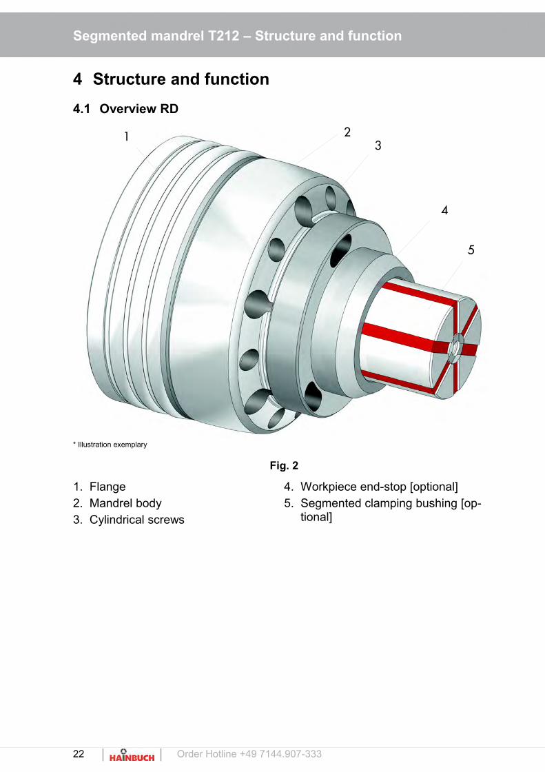
4.1 Overview RD
* Illustration exemplary
Fig. 2
1. Flange2. Mandrel body3. Cylindrical screws
4. Workpiece end-stop [optional]5. Segmented clamping bushing [op-
tional]
22 Order Hotline +49 7144.907-333
213
5
4

Segmented mandrel T212 – Structure and function
4.2 Overview SE
6. x
Fig. 3
1. Flange2. Mandrel body3. Cylindrical screws
4. Workpiece end-stop [optional]5. Segmented clamping bushing [op-
tional]
4.3 Brief description
The segmented clamping bushing type 212 functionsaccording to the pull-back principle.It is a very robust and highly accurate clamping de-vice with a concentricity < 0.010 mm.By vulcanized segmented clamping bushing made ofhardened steel and the pull-back principle at the workpiece end-stop, a high rigidity and vibration attenua-tion achieved.
4.4 Optional Accessories
The accessories described here are not included in thescope of delivery.
Specially developed segmented clamping bushingsmatch to the respective maximum RPM are availablefor each clamping device. Trouble-free and precisefunction of HAINBUCH clamping devices is only en-
Order Hotline +49 7144.907-333 23
21
3 5
4
Segmented mandrel T212 – Structure and function
sured when using original HAINBUCH segmentedclamping bushings.
Lubricating grease and grease gun are required forcleaning and preservation of the clamping device. Thelubricating grease is also specially matched for protec-tion of the vulcanized segments of the segmentedclamping bushings and increase their service life andelasticity by a significant factor.
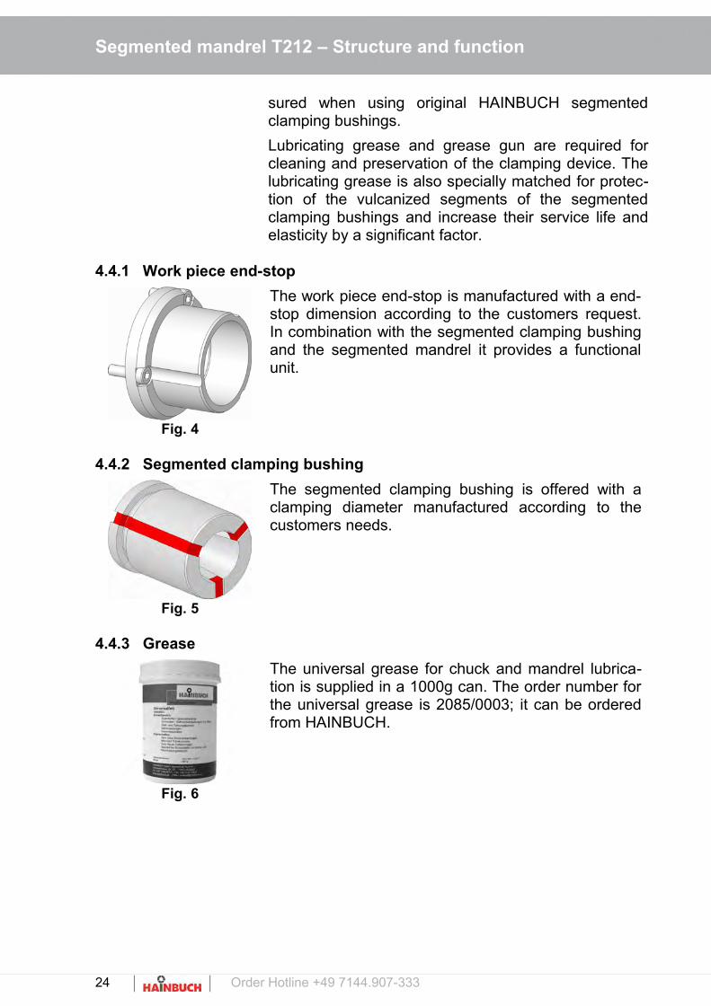
4.4.1 Work piece end-stop
Fig. 4
The work piece end-stop is manufactured with a end-stop dimension according to the customers request.In combination with the segmented clamping bushingand the segmented mandrel it provides a functionalunit.
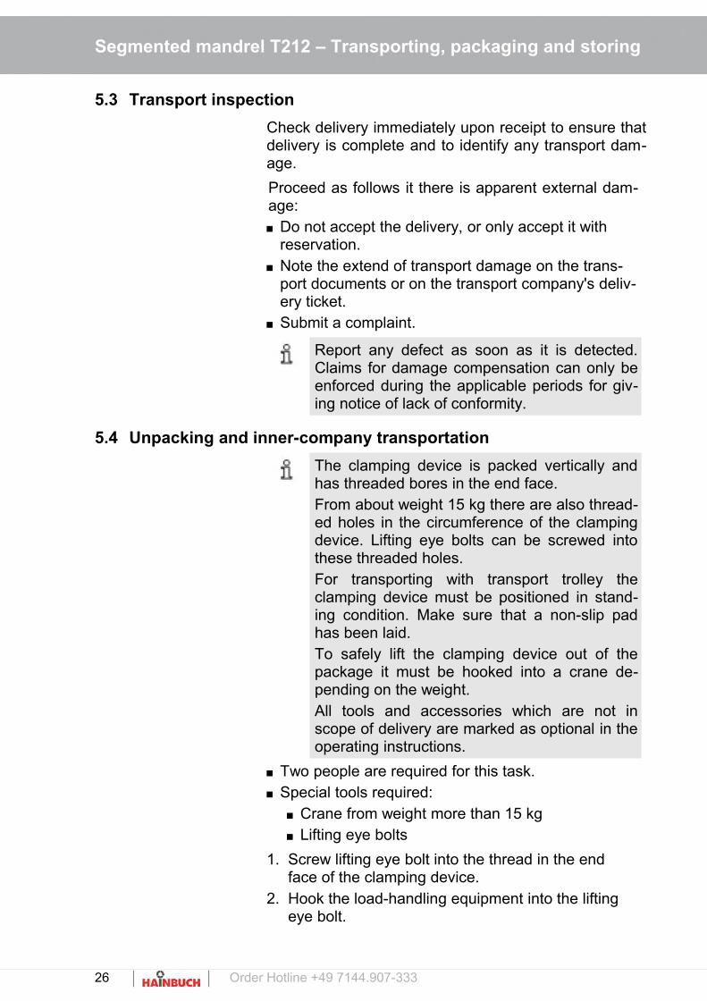
4.4.2 Segmented clamping bushing
Fig. 5
The segmented clamping bushing is offered with aclamping diameter manufactured according to thecustomers needs.
4.4.3 Grease
Fig. 6
The universal grease for chuck and mandrel lubrica-tion is supplied in a 1000g can. The order number forthe universal grease is 2085/0003; it can be orderedfrom HAINBUCH.
24 Order Hotline +49 7144.907-333

Segmented mandrel T212 – Transporting, packaging and storing
5 Transporting, packaging and storing
5.1 Safety instructions for transporting
Unbalanced package WARNING!
Danger of falling due to an unbalanced package
Packed goods can have an unbalanced pack-age. If attached incorrectly the package can tipand cause life-threatening injuries. Note the markings on the packages. Attach the crane hook in such a manner that
it is located above the center of gravity. Carefully lift and see if the load tilts. If neces-
sary change the attachment.
Transport!
For transport always use a suitable clamping means / crane.
Make sure that a rolling / falling of the clamp-ing device is not possible.
5.2 Symbols on the packaging
Fragile
Identifies packages with fragile or sensitive contents.Handle the packed goods with care; do not allowthem to fall, and do not subject them to impact.
Protect from moisture
Keep packed goods dry and protected against mois-ture.
Order Hotline +49 7144.907-333 25
Segmented mandrel T212 – Transporting, packaging and storing
5.3 Transport inspection
Check delivery immediately upon receipt to ensure thatdelivery is complete and to identify any transport dam-age.
Proceed as follows it there is apparent external dam-age: Do not accept the delivery, or only accept it with
reservation. Note the extend of transport damage on the trans-
port documents or on the transport company's deliv-ery ticket.
Submit a complaint.
Report any defect as soon as it is detected.Claims for damage compensation can only beenforced during the applicable periods for giv-ing notice of lack of conformity.
5.4 Unpacking and inner-company transportation
6. x The clamping device is packed vertically andhas threaded bores in the end face.From about weight 15 kg there are also thread-ed holes in the circumference of the clampingdevice. Lifting eye bolts can be screwed intothese threaded holes.For transporting with transport trolley theclamping device must be positioned in stand-ing condition. Make sure that a non-slip padhas been laid.To safely lift the clamping device out of thepackage it must be hooked into a crane de-pending on the weight.All tools and accessories which are not inscope of delivery are marked as optional in theoperating instructions.
Two people are required for this task. Special tools required:
Crane from weight more than 15 kg Lifting eye bolts
1. Screw lifting eye bolt into the thread in the end face of the clamping device.
2. Hook the load-handling equipment into the lifting eye bolt.
26 Order Hotline +49 7144.907-333

Segmented mandrel T212 – Transporting, packaging and storing
3. Use a crane to carefully lift the clamping device outof the transport packaging and put it down on a stable, level substrate.
5.5 Packaging
About the packaging Individual packages are packed according to the ex-pected transport conditions. Environmentally-friendlymaterials have been used exclusively for the packag-ing.Packaging should protect the specific componentsfrom transport damage, corrosion, and other damageuntil installation. Therefore do not destroy the packag-ing, remove it just before installation.
The packed goods are sealed in foil airtightand packed in cartons. See the »TechnicalData« section for the specific weight of the re-spective sizes.
Handling packaging materials
Dispose of packaging materials in accordance withthe respectively valid statutory regulations and localguidelines.
NOTE!
Improper disposal causes environmental damage!
Packaging materials are valuable raw materi-als and in many cases they can be reused, orthey can be effectively treated and recycled. Dispose of packaging materials in an envi-
ronmentally responsible manner. Comply with locally applicable disposal
guidelines. If necessary commission a spe-cialized company to dispose of packaging.
Order Hotline +49 7144.907-333 27
Segmented mandrel T212 – Transporting, packaging and storing
5.6 Storing
Under certain circumstances instructions forstorage and subsequent storage are affixed tothe packages that extend beyond the require-ments cited here.Comply with these instructions accordingly.
Storage of packages Only store packages under the following conditions: Do not store outdoors. Store in a dry and dust-free location Do not expose to aggressive media Protect from direct sunlight Avoid mechanical vibration Storage temperature: 15 bis 35 °C Relative humidity: max. 60 % For storage periods longer than 3 months:
Check the general condition of all parts and the packaging at regular intervals.
Touch up or re-apply anti-corrosion agents as needed
Subsequent storage of the clamping device
Only re-store the clamping device under the followingconditions: Thoroughly clean the clamping device prior to sub-
sequent storage [see section »Cleaning«] Thoroughly oil and grease the clamping device.
[see section »Cleaning«] Store the clamping device in airtight foil The clamping device must be stored securely in po-
sition. If this is not guaranteed, use a suitable con-tainer for the clamping device or equip the shelf witha circumferential securing edge.
28 Order Hotline +49 7144.907-333

Segmented mandrel T212 – Assembly
6 Assembly
WARNING!
During the initial installation of the clampingdevice severe injuries may occur. The initial installation must be done only by
qualified personnel. All screws remaining in the clamping must be
tightened firmly. All tools and keys must be removed after in-
stallation.
WARNING
Risk of injury due to stored energy!
The clamping device can be designed with discsprings. These disc springs are under perma-nent tension! The release of the stored energycan cause injuries! By loosening the corresponding screws they
have to be operated continuously alternately to reduce the clamping pressure to a mini-mum!
Particularly cautious approach is required! For cleaning and maintenance disassemble
the clamping device from the machine! Always wear personal protective equipment!
6.1 Pre-consideration
Screws are tightened according to the size of the screw and the general torque.To avoid axis-parallel warpage under load and to get stiffness turn in the screws evenly.
To avoid precision error clean the screw joint sur-faces and also the mating surfaces, see »Mainte-nance«.The ex works wetting of the plate surfaces and the clamping element is only corrosion protection. It's not functionally lubricated.
The insertion of lubricant is provided only on the mechanical surfaces. Pay attention to the instruc-tions for lubricants in the chapter »Maintenance«.
Order Hotline +49 7144.907-333 29

Segmented mandrel T212 – Assembly
Avoid too much lubricant on the bearing surface, as this can cause face runout.
Seal rings (e.g. o-ring, quad-ring seal) and sealing surfaces must be lubricated.Note the information in the chapter »Maintenance«.
Note that the function surfaces (plate surface, mat-ing surface, cone surface and seal surface) may notbe damaged.
CAUTION!
Wear safety shoes during the assembly andmaintenance work.Make sure that the starting of the spindle is im-possible.
6.2 Preparations
The total weight of the clamping device, consisting ofspindle flange and clamping unit, depends on the sizeand can be as much as 50 kg.Depending on the weight, to safely lift the clampingdevice out of the package and position it in the ma-chine it must be hooked into a crane.
WARNING!
Danger of injury due to falling components!
When mounting components can fall andcause severe injury and material damage. Two people are always required for this task. Use a crane. For mounting on a vertically hanging spindle,
a suitable mounting aide is necessary.
If the clamping device is delivered in combination witha flange, the flange must be assembled before theclamping device!
4. x Special tools required: Allen wrench Oil stone Crane Eye bolts
30 Order Hotline +49 7144.907-333

Segmented mandrel T212 – Assembly
Fig. 7
1. Loosen, unscrew and remove the cylindrical screws [1] in the clamping device; use an allen wrench.
Fig. 8
2. Remove the flange from the clamping device.3. Clean the mating surfaces at flange and clamping
device with a soft, lint-free cloth and remove all oil and grease residues.
4. Hone the mating surfaces on the spindle flange with an oil stone.
6.3 Assembly
The segmented mandrel is delivered in assembledcondition and with pre-assembled clamping unit.
The assembly differs by the machine to which theclamping device will be assembled: Assembly with HSK Assembly with machine spindle Assembly with capteX Assembly with quick change interface Assembly with hydraulic
WARNING!
Danger of injury due to unintentional start-up of the tool spindle!
Unexpected start up of the tool spindle cancause severe injury. Prior to switching on automatic mode close
all protective doors or hoods that are present on the machine tool.
Unscrew all ring nuts from the clamping de-vice and remove them from the interior of themachine.
Only run the machine in set-up mode or jog mode.
Always remove immediately all the tools and wrenches from the clamping device after use.
Order Hotline +49 7144.907-333 31
1

Segmented mandrel T212 – Assembly
WARNING!
Risk of injury!
By operating the clamping device withoutchanging parts [clamping head, segmentedclamping bushing, work piece end-stops ...]there is an increased risk of crushing injuriesby the stroke of the moving components of theclamping device.By uncontrolled discharge of the clampingprocess [e.g. by incorrect installation of the en-ergy supply or faulty programming] there is anincreased danger.
WARNING!
Risk of injury!
Bending in the working area of the machinecan cause severe head injuries!
CAUTION!
Risk of injury!
Unexpected start up of the tool spindle cancause severe injury. Make sure that the system is pressure-free
and that a restart of the machine can be ex-cluded!
Risk of injury!
Contamination of the mechanism can influ-ence/reduce the stroke, thus the clampingforce is reduced and thus, the work piece is notproperly tightened and can be thrown out. Clean the product regularly [see chapter
»Maintenance and service«].
32 Order Hotline +49 7144.907-333

Segmented mandrel T212 – Assembly
Risk of injury!
If the clamping pressure is too low clampedwork piece may be thrown out.If the clamping pressure is too high severedamages of the components of the clampingdevice may occur the throwing out of the workpiece. Before operation set the operation pressure
back to operation level. The operating pressure should be checked
and adjusted regularly! The dimension of the work pieces should be
checked regularly [clamping-ø]!
Transport!
For transport always use a suitable clamping means / crane.
Make sure that a rolling / falling of the clamp-ing device is not possible.
WARNING!
Danger of injury due to vertical suspended spindle!
Bending into the machine work are when as-sembling overhead can cause severe head in-juries. Secure components prior to overhead as-
sembly. For assembly on a vertically suspended spin-
dle always use a suitable mounting aid.
6.3.1 Assembling the draw tube adapter
Fig. 9
5. xxx
1. Put the machine in set up mode.2. Wipe off the mating surfaces of the machine spin-
dle with a soft, lint-free cloth and remove all oil andgrease residues.
3. Screw the draw tube adapter on the draw tube of the machine till end stop.
Order Hotline +49 7144.907-333 33

Segmented mandrel T212 – Assembly
6.3.2 Assembling the flange
6. x NOTE!
Material damage due to wrong tightening torque of the cylindrical screws in the spin-dle flange!
The tightening torque of the cylindrical screwsis prescribed by the spindle or machine manu-facturer. Incorrect tightening torque of thecylindrical screws in the flange can cause sig-nificant material damage on the clamping de-vice and on the machine. Only tighten the cylindrical screws of the
spindle with the torque prescribed by the spindle or machine manufacturer.
Fig. 10
1. Put the machine in set up mode.2. Wipe off the mating surfaces of the machine spin-
dle with a soft, lint-free cloth and remove all oil andgrease residues.
3. Lift the flange into the machine by hand or with the aid of a crane and place it on the machine spindle. Position the flange on the machine spindle with theaid of the bores.
4. Screw all cylindrical screws into the flange wit an allen wrench and hand tighten in a cross pattern.
NOTE!
Material damage is possible if the eye bolts are left in the spindle flange!
Eye bolts that are left in the clamping devicecan significantly damage or even destroy lathe,clamping device and work piece. Always remove eye bolts immediately after
mounting the clamping device in the lathe.
NOTE!
Material damage due to insufficient face runand concentricity!
Due to insufficient face run and concentricitywork pieces can be damaged during process-ing. After each mounting check, and if necessary
readjust, the face run and concentricity of theclamping device.
34 Order Hotline +49 7144.907-333

Segmented mandrel T212 – Assembly
Checking face run
Special tools required: Dial indicator Plastic tip hammer
Fig. 11
1. Place the magnetic bas of the dial indicator on the inside of the machine.
2. Place the dial indicator for face run on the face of the clamping unit.
3. Use a plastic tip hammer to carefully knock the clamping unit into position.
4. Tighten the cylindrical screws with a torque wrenchin a cross pattern [see section »Screw tightening torque«].
For exact adjustment, if necessary loosen thecylindrical screws several turns and retightenin a cross pattern.
5. Wipe off the taper of the the segmented mandrel with a soft, lint-free cloth and remove all oil and grease residues.
Checking concentricity
Special tools required: Dial indicator Plastic tip hammer Torque wrench
Fig. 12
1. Place the magnetic base of the dial indicator on the inside of the machine.
2. Place the dial indicator [2] for concentricity on the clamping taper [1].
3. Adjust the flange in such a manner that the dial in-dicator shows the value »0«.
For exact adjustment, if necessary loosen thecylindrical screws several turns and retightenin a cross pattern.
Order Hotline +49 7144.907-333 35

Segmented mandrel T212 – Assembly
4. Tighten the cylindrical screws crosswise by using atorque wrench [see chapter »Screw tightening torque«].
5. Remove all tools from the machine area.
6.3.3 Assembly of the segmented mandrel [HSK]
6. x Two people are required for this task!Special tools required: Allen wrench Crane Eye bolts
WARNING!
Crushing danger due to machine move-ment!
Due to the design of the drawtube a gap mayresult between drawtube adapter and clampingdevice / clamping unit. When assembling theclamping device / clamping unit there is a highrisk squeezing danger. Due to this gap there isa high risk of crushing, which can lead to seri-ous injuries. Never reach into the gap between the ma-
chine / spindle flange and clamping device!
1. Put the machine in set up mode.2. Remove all tools from the interior of the machine.3. Set the clamping pressure of the machine tool on
the lowest setting.4. Move the drawtube of the machine tool into front
stop position.
Fig. 13
5. Remove the coupling from the segmented mandrel.6. Screw in the transport eye bolts into the circumfer-
ence of the mandrel.7. Loosen the HSK tool clamping of the machine.
NOTE!
Risk of injury due to improper connection of thehydraulic connections. Note the labeling of the hydraulic connec-
tions!
8. Put the segmented mandrel on the machine.9. Clamp the HSK tool clamping of the machine.
36 Order Hotline +49 7144.907-333

Segmented mandrel T212 – Assembly
Adjusting The segmented mandrel is aligned by the factory.If the perpendicularity deviates around more than0.005 mm you can align the mandrel as follows:
Fig. 14
10.Loosen the cylindrical screws [C] only for a few turns without removing them.
11.Check the concentricity at the clamping cone of thesegmented mandrel [max. 0.005 mm], correct if necessary carefully with a plastic hammer.
12.Tighten the cylindrical screws [C] crosswise with the correct tightening torque.
13.Set the clamping pressure back to operating level.
Order Hotline +49 7144.907-333 37
C

Segmented mandrel T212 – Assembly
WARNING!
Risk of injury from stored energy!
The stored energy of the springs can lead to injuries.
The constructive design allows the removing of the springs, without any residual energy discharges.
By carefully working it is ensured that the springs are power-free during disassembly!
6.3.4 Assembly of the segmented mandrel [machine spindle]
14.x Two people are required for this task!Special tools required: Allen wrench Crane Eye bolts
WARNING!
Crushing danger due to machine move-ment!
Due to the design of the draw tube a gap mayresult between draw tube adapter and clamp-ing device / clamping unit. When assemblingthe clamping device / clamping unit there is ahigh risk squeezing danger. Due to this gapthere is a high risk of crushing, which can leadto serious injuries. Never reach into the gap between the ma-
chine / spindle flange and clamping device!
1. Put the machine in set up mode.2. Remove all tools from the interior of the machine.3. Set the clamping pressure of the machine tool on
the lowest setting.
Risk of injury!
Leaking hydraulic oil can cause serious injury. Make sure that the system is depressurized
during installation!
38 Order Hotline +49 7144.907-333

Segmented mandrel T212 – Assembly
Fig. 15
4. Move the draw tube of the machine tool into front stop position.
5. Screw in the transport eye bolts into the circumfer-ence of the mandrel.
6. Put the segmented mandrel on the pre-assembled spindle flange on the machine spindle by using a crane.
7. Screw in all cylindrical screws into the segmented mandrel with an allen wrench and tighten them only finger-tight in a cross pattern.
8. Increase the clamping pressure again to the level required for machining.
WARNING!
Risk of injury from stored energy!
The stored energy of the springs can lead to injuries.
The constructive design allows the removing of the springs, without any residual energy discharges.
By carefully working it is ensured that the springs are power-free during disassem-bly!
Adjusting The segmented mandrel is aligned by the factory.If the perpendicularity deviates around more than0.005 mm you can align the mandrel as follows:
Order Hotline +49 7144.907-333 39

Segmented mandrel T212 – Assembly
Fig. 16
9. Disassemble the segmented mandrel from the ma-chine.
10.Check the concentricity of the spindle flange [C] to the mandrels body [D] [max. 0.005 mm].
11.Loosen the cylindrical screw [B] only lightly and correct carefully with a plastic hammer till the con-centricity is may. 0.005 mm.
12.Tighten the cylindrical screws [B] firmly with the correct tightening torque.
13.Put the segmented mandrel on the machine.
14.Tighten the cylindrical screws [B] only lightly.15.Check the concentricity of the spindle flange [C]
[max. 0.005 mm], correct if necessary carefully with a plastic hammer.
16.Tighten the cylindrical screws [E] firmly with the correct tightening torque.
40 Order Hotline +49 7144.907-333
B
D
C
E
Segmented mandrel T212 – Assembly
6.3.5 Assembly of the segmented mandrel [capteX B]
Two people are required for this task!Special tools required: Allen wrench Crane Eye bolts
17.x Risk of injury!
Leaking hydraulic oil can cause serious injury. Make sure that the system is depressurized
during installation!
WARNING!
Crushing danger due to machine move-ment!
Due to the design of the drawtube a gap mayresult between drawtube adapter and clampingdevice / clamping unit. When assembling theclamping device / clamping unit there is a highrisk squeezing danger. Due to this gap there isa high risk of crushing, which can lead to seri-ous injuries. Never reach into the gap between the ma-
chine / spindle flange and clamping device!
1. Put the machine in set up mode.2. Remove all tools from the interior of the machine.3. Set the clamping pressure of the machine tool on
the lowest setting.4. Move the drawtube of the machine tool into front
stop position.
Order Hotline +49 7144.907-333 41

Segmented mandrel T212 – Assembly
Fig. 17
5. Screw in the transport eye bolts into the circumfer-ence of the mandrel.
6. Put the clamping device [C] on the machine adapter [D] by using a crane, position it by the po-sitioning pin [E].
7. Turn the actuating screw [F] by using a key [in scope of delivery] with the correct tightening torque.
WARNING!
Risk of injury from stored energy!
The stored energy of the springs can lead to injuries.
The constructive design allows the removing of the springs, without any residual energy discharges.
By carefully working it is ensured that the springs are power-free during disassembly!
42 Order Hotline +49 7144.907-333
C
D
E
F

Segmented mandrel T212 – Assembly
6.3.6 Assembly of the segmented mandrel [quick change-over interface]8. x
Fig. 18
The assembly of the segmented mandrel from thequick change machine adapter is described in themanual of the machine adapter.
6.3.7 Checking and adjusting the face run and the concentricity [RD]
9. x NOTE!
Material damage due to insufficient face runand concentricity!
Due to insufficient face run and concentricitywork pieces can be damaged during process-ing. After each mounting check, and if necessary
readjust, the face run and concentricity of theclamping device.
Checking face run
Special tools required: Dial indicator Plastic tip hammer
Fig. 19
1. Place the magnetic base of the dial indicator on the inside of the machine.
2. Place the dial indicator for face run on the face of the clamping unit.
3. Use a plastic tip hammer to carefully knock the clamping unit into position.
4. Tighten the cylindrical screws with a torque wrenchin a cross pattern [see section »Screw tightening torque«].
For exact adjustment, if necessary loosen thecylindrical screws several turns and retightenin a cross pattern.
5. Wipe off the taper of the the segmented mandrel with a soft, lint-free cloth and remove all oil and grease residues.
Order Hotline +49 7144.907-333 43

Segmented mandrel T212 – Assembly
Checking concentricity
Special tools required: Dial indicator Plastic tip hammer Torque wrench
Fig. 20
6. Place the magnetic base of the dial indicator on the inside of the machine.
7. Place the dial indicator [2] for concentricity on the clamping taper [1].
8. Adjust the segmented mandrel in such a manner that the dial indicator shows the value »0«.
For exact adjustment, if necessary loosen thecylindrical screws several turns and retightenin a cross pattern.
6.3.8 Checking and adjusting the face run and the concentricity [SE]
9. x NOTE!
Material damage due to insufficient face runand concentricity!
Due to insufficient face run and concentricitywork pieces can be damaged during process-ing. After each mounting check, and if necessary
readjust, the face run and concentricity of theclamping device.
Checking face run
Special tools required: Dial indicator Plastic tip hammer
1. Place the magnetic base of the dial indicator on the inside of the machine.
2. Place the dial indicator for face run on the face of the clamping unit.
3. Use a plastic tip hammer to carefully knock the clamping unit into position.
44 Order Hotline +49 7144.907-333

Segmented mandrel T212 – Assembly
Fig. 21
4. Tighten the cylindrical screws with a torque wrenchin a cross pattern [see section »Screw tightening torque«].
For exact adjustment, if necessary loosen thecylindrical screws several turns and retightenin a cross pattern.
5. Wipe off the taper of the the segmented mandrel with a soft, lint-free cloth and remove all oil and grease residues.
Checking concentricity
Special tools required: Dial indicator Plastic tip hammer Torque wrench
Fig. 22
1. Place the magnetic base of the dial indicator on the inside of the machine.
2. Place the dial indicator [2] for concentricity on the cylindrical collar [see fig].
3. Adjust the segmented mandrel in such a manner that the dial indicator shows the value »0«.
For exact adjustment, if necessary loosen thecylindrical screws several turns and retightenin a cross pattern.
6.3.9 Installation of the hydraulic segmented mandrel
4. x Two people are required for this task.Special tools required: Allen wrench Tool for expander Crane and eye bolts from weight 15 kg
Depending on the model of the hydraulic segmentedmandrel the hydraulic connection is usually by the base plate or alternatively at the side of the stationary chuckThe hydraulic segmented mandrel can be centered bythe outer fit or the inner fit.
Order Hotline +49 7144.907-333 45
Segmented mandrel T212 – Assembly
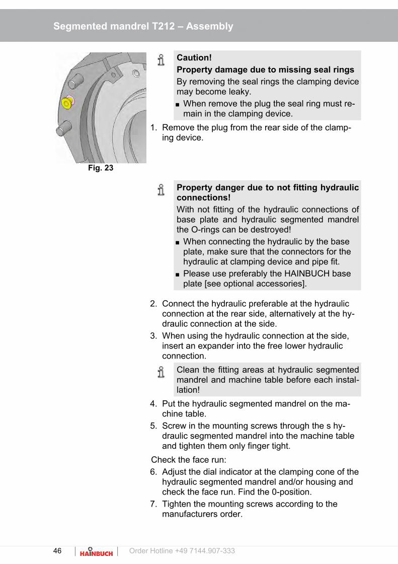
Fig. 23
Caution!Property damage due to missing seal ringsBy removing the seal rings the clamping devicemay become leaky. When remove the plug the seal ring must re-
main in the clamping device.
1. Remove the plug from the rear side of the clamp-ing device.
Property danger due to not fitting hydraulicconnections!With not fitting of the hydraulic connections ofbase plate and hydraulic segmented mandrelthe O-rings can be destroyed! When connecting the hydraulic by the base
plate, make sure that the connectors for the hydraulic at clamping device and pipe fit.
Please use preferably the HAINBUCH base plate [see optional accessories].
2. Connect the hydraulic preferable at the hydraulic connection at the rear side, alternatively at the hy-draulic connection at the side.
3. When using the hydraulic connection at the side, insert an expander into the free lower hydraulic connection.
Clean the fitting areas at hydraulic segmentedmandrel and machine table before each instal-lation!
4. Put the hydraulic segmented mandrel on the ma-chine table.
5. Screw in the mounting screws through the s hy-draulic segmented mandrel into the machine table and tighten them only finger tight.
Check the face run:6. Adjust the dial indicator at the clamping cone of the
hydraulic segmented mandrel and/or housing and check the face run. Find the 0-position.
7. Tighten the mounting screws according to the manufacturers order.
46 Order Hotline +49 7144.907-333
Segmented mandrel T212 – Assembly
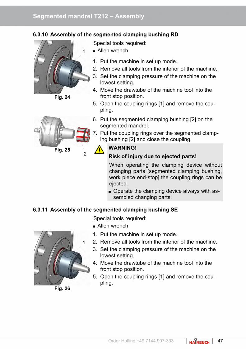
6.3.10 Assembly of the segmented clamping bushing RD
Fig. 24
Special tools required: Allen wrench8. x
1. Put the machine in set up mode.2. Remove all tools from the interior of the machine.3. Set the clamping pressure of the machine on the
lowest setting.4. Move the drawtube of the machine tool into the
front stop position.5. Open the coupling rings [1] and remove the cou-
pling.
Fig. 25
6. Put the segmented clamping bushing [2] on the segmented mandrel.
7. Put the coupling rings over the segmented clamp-ing bushing [2] and close the coupling.
WARNING!
Risk of injury due to ejected parts!
When operating the clamping device withoutchanging parts [segmented clamping bushing,work piece end-stop] the coupling rings can beejected. Operate the clamping device always with as-
sembled changing parts.
6.3.11 Assembly of the segmented clamping bushing SE
8. x Special tools required: Allen wrench
Fig. 26
1. Put the machine in set up mode.2. Remove all tools from the interior of the machine.3. Set the clamping pressure of the machine on the
lowest setting.4. Move the drawtube of the machine tool into the
front stop position.5. Open the coupling rings [1] and remove the cou-
pling.
Order Hotline +49 7144.907-333 47
2
1
1

Segmented mandrel T212 – Assembly
Fig. 27
Fig. 28
6. Put the segmented clamping bushing [2] on the segmented mandrel.
NOTE!
The grooves of the segmented clamping bush-ing must engage into the opposing keys on thesegmented mandrel!
NOTE!
In incorrect assembly lubricating grease ispressed through the vulcanization. The vulcan-ization can be damaged! Make sure when installing the segment
clamping bushing that the vulcanization fits always on the edge of the mandrel body in which are no lubrication grooves!
7. Put the coupling rings over the segmented clamp-ing bushing [2] and close the coupling.
WARNING!
Risk of injury due to ejected parts!
When operating the clamping device withoutchanging parts [segmented clamping bushing,work piece end-stop] the coupling rings can beejected. Operate the clamping device always with as-
sembled changing parts.
6.3.12 Assembling of the work piece end-stop
8. x Special tools required: Torque wrench
Fig. 29
1. Put the machine tool in set up mode.2. Remove all tools from the interior of the machine.3. Set the clamping pressure of the machine tool on
the lowest setting.4. Move the drawtube of the machine tool into the
front stop position.5. Put the work piece end-stop on the segmented
mandrel.6. Screw in all cylindrical screws into the work piece
end-stop with an allen wrench and tighten them clockwise with an allen wrench [see section »Screw tightening torque«].
48 Order Hotline +49 7144.907-333
2

Segmented mandrel T212 – Assembly
WARNING!
Risk of injury!
Tools and gages that are thrown out of the ma-chine can cause injury. Remove all tools and gages from the working
area of the machine before the machine is started up.
Risk of injury!
If the clamping pressure is too low clampedwork piece may be thrown out.If the clamping pressure is too high severedamages of the components of the clampingdevice may occur the throwing out of the workpiece. Before operation set the operation pressure
back to operation level. The operating pressure should be checked
and adjusted regularly!
WARNING!
Slipping danger due to escaping hydraulic fluid!
Escaping (sprayed out) hydraulic oil can causeserious injuries. Make sure that all o-rings/seals for the hy-
draulic / pneumatic interfaces are available and in undamaged condition.
Make sure that the clamping device is empty and leakage of hydraulic fluid is avoided.
Order Hotline +49 7144.907-333 49

Segmented mandrel T212 – Assembly
6.4 Work piece
WARNING!
Risk of injury due to thrown out parts!
During clamping of the work piece and the pro-cessing parts can be thrown and cause severeinjuries and property damage. Check the clamping diameter of the work
piece. Tighten only work pieces that meet the di-
mensional requirements. For clamping very long work pieces use in
addition a tailstock / a steady rest for support. Do not exceed the maximum permissible
clamping force. Make sure that the applied clamping force is
set correctly [neither too high nor too low].
CAUTION
Risk of injury!
When placing the work piece: Make sure that the hands / fingers may not
be clamped between the flange and the workpiece!
50 Order Hotline +49 7144.907-333
Segmented mandrel T212 – Assembly
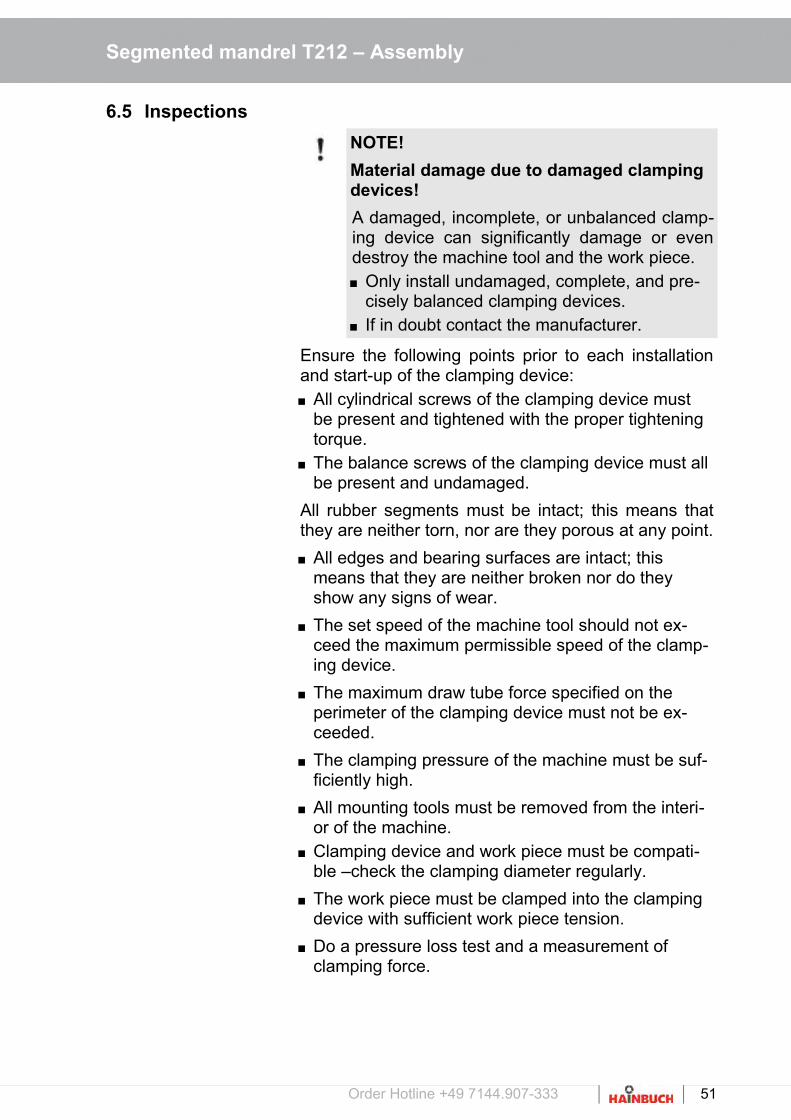
6.5 Inspections
NOTE!
Material damage due to damaged clamping devices!
A damaged, incomplete, or unbalanced clamp-ing device can significantly damage or evendestroy the machine tool and the work piece. Only install undamaged, complete, and pre-
cisely balanced clamping devices. If in doubt contact the manufacturer.
Ensure the following points prior to each installationand start-up of the clamping device: All cylindrical screws of the clamping device must
be present and tightened with the proper tightening torque.
The balance screws of the clamping device must all be present and undamaged.
All rubber segments must be intact; this means thatthey are neither torn, nor are they porous at any point.
All edges and bearing surfaces are intact; this means that they are neither broken nor do they show any signs of wear.
The set speed of the machine tool should not ex-ceed the maximum permissible speed of the clamp-ing device.
The maximum draw tube force specified on the perimeter of the clamping device must not be ex-ceeded.
The clamping pressure of the machine must be suf-ficiently high.
All mounting tools must be removed from the interi-or of the machine.
Clamping device and work piece must be compati-ble –check the clamping diameter regularly.
The work piece must be clamped into the clamping device with sufficient work piece tension.
Do a pressure loss test and a measurement of clamping force.
Order Hotline +49 7144.907-333 51

Segmented mandrel T212 – Assembly
6.6 Control of the stroke position
WARNING!
Crushing danger from moving parts!
Crushing danger from moving parts duringcontrolling the stroke position!Gaps, caused while controlling the stroke posi-tion, can cause severe injury. Only do the controlling of the stroke position
with assembled changing parts. Only run the machine in set-up mode or jog
mode. Do not reach into moving parts or handle
moving parts during operation. Note the gap dimensions of moving parts. Wearing of gloves / [PSA] is required!
6.7 Activities after production is concluded
7. x 1. Move the clamping device into unclamped position.2. Switch off the machine tool and safeguard it from
being switched on again.3. Open the protective door or hood.4. Clean the clamping device and a possibly mounted
adaptation clamping device and adapter of chips and production residues using a soft, lint-free cloth and oil them lightly.
5. Close the protective door or hood.
52 Order Hotline +49 7144.907-333

Segmented mandrel T212 – Disassembly
7 Disassembly
If there is break in production that lasts longer than 3days, the clamping device must be disassembled andproperly stored in accordance with the manufacturer'sspecifications [see section »Transport, packaging,storage«].
Prior to disassembling: Put the machine in set up mode. Remove fuels and auxiliary materials, as well as
residual processing materials and dispose of these items in an environmentally-responsible manner.
7.1 Safety
Safeguarding against restart
DANGER!
Life-threatening danger if restarted without authorization
When disassembling there is danger of the en-ergy supply being switched on inadvertently.This poses a life-threatening hazard for per-sons in the danger zone. Prior to starting the tasks switch off all energy
supplies and safeguard them from being switched on again.
WARNING!
Danger of injury due to falling components!
When mounting components can fall andcause severe injury and material damage. Two people are always required for this task. Use a crane. For assembly on a vertically suspended spin-
dle always use a suitable mounting aid.
Order Hotline +49 7144.907-333 53

Segmented mandrel T212 – Disassembly
WARNING!
Danger of injury due to vertical suspended spindle!
Bending into the machine work are when as-sembling overhead can cause severe head in-juries. Secure components prior to overhead as-
sembly. For assembly on a vertically suspended spin-
dle always use a suitable mounting aid.
WARNING
Risk of injury due to stored energy!
The clamping device can be designed with discsprings. These disc springs are under perma-nent tension! The release of the stored energycan cause injuries! By loosening the corresponding screws they
have to be operated continuously alternately to reduce the clamping pressure to a mini-mum!
Particularly cautious approach is required! For cleaning and maintenance disassemble
the clamping device from the machine! Always wear personal protective equipment!
Transport!
For transport always use a suitable clamping means / crane.
Make sure that a rolling / falling of the clamp-ing device is not possible.
54 Order Hotline +49 7144.907-333

Segmented mandrel T212 – Disassembly
7.2 Disassembling the clamping device
7.2.1 Disassembling the work piece end-stop
6. x Special tools required: Allen wrench
Fig. 30
1. Put the machine tool in set up mode.2. Remove all tool from the interior of the machine.3. Set the clamping pressure of the machine tool on
the lowest setting.4. Move the drawtube of the machine tool into the
front stop position.5. Loosen, unscrew and remove the cylindrical
screws.6. Remove the work piece end-stop from the seg-
mented mandrel.
7.2.2 Disassembling the segmented clamping bushing [RD/SE]
7. x Special tools required: Wrench
Fig. 31
1. Put the machine tool in set up mode.2. Remove all tool from the interior of the machine.3. Set the clamping pressure of the machine tool on
the lowest setting.4. Move the drawtube of the machine tool into the
front stop position.5. Open the coupling rings [1] and remove the cou-
pling.6. Remove the segmented clamping bushing [2] from
the segmented mandrel.
Order Hotline +49 7144.907-333 55
1
2

Segmented mandrel T212 – Disassembly
7.2.3 Disassembling the segmented mandrel [HSK]
7. x Two people are required for this task!Special tools required: Allen wrench Crane Eye bolts
1. Put the machine tool in set up mode.2. Remove all tools from the interior of the machine.3. Set the clamping pressure of the machine tool on
the lowest setting.4. Move the drawtube of the machine tool into the
front stop position.
Fig. 32
5. Screw in the eye bolts [A] into the circumference ofthe segmented mandrel.
6. Loosen the HSK tool clamping of the machine.7. Remove the segmented mandrel from the machine
by using a crane.
7.2.4 Disassembling the segmented mandrel [machine spindle]
8. x Two people are required for this task!Special tools required: Allen wrench Crane Eye bolts
1. Put the machine tool in set up mode.2. Remove all tools from the interior of the machine.3. Set the clamping pressure of the machine tool on
the lowest setting.4. Move the drawtube of the machine tool into the
front stop position.
Fig. 33
5. Loosen, unscrew and remove the cylindrical screws.
6. Remove the segmented mandrel from the flange by using a crane.
56 Order Hotline +49 7144.907-333
A

Segmented mandrel T212 – Disassembly
7.2.5 Disassembling the segmented mandrel [capteX B]
7. x Two people are required for this task!Special tools required: Allen wrench Crane Eye bolts
1. Put the machine tool in set up mode.2. Remove all tools from the interior of the machine.3. Set the clamping pressure of the machine tool on
the lowest setting.4. Move the drawtube of the machine tool into the
front stop position.5. Screw in the transport eye bolts into the circumfer-
ence of the mandrel.
Fig. 34
Risk of injury!
Leaking hydraulic oil can cause serious injury. Make sure that the system is depressurized
during installation!
6. Loosen the actuating screws [F] by using a key [in scope of delivery].
7. Remove the segmented mandrel from the ma-chine.
Order Hotline +49 7144.907-333 57
F
C

Segmented mandrel T212 – Disassembly
7.2.6 Disassembly of the segmented mandrel [quick-change interface]8. x
Fig. 35
The disassembly of the segmented mandrel from thechick-change machine adapter is described in themanual of the machine adapter.
7.2.7 Disassembly of the hydraulic mandrel
9. x Two people are required.Special tools required: Allen wrench crane and eye bolts from weight 15 kg
Fig. 36
1. Loosen and remove the mounting screws.2. Disconnect the hydraulic connection at the station-
ary chuck.3. Remove the stationary chuck from the machine ta-
ble.
Clean the mounting surfaces of the stationarychuck and the machine table after each disas-sembly!
7.2.8 Disassembling the flange
Fig. 37
4. xxx
1. Put the machine tool in set up mode.2. Loosen, unscrew and remove the cylindrical
screws.3. Remove the flange by hand from the machine
spindle.4. Wipe off the mating surfaces at the machine spin-
dle with a soft, lint-free cloth and remove all oil andgrease residues.
58 Order Hotline +49 7144.907-333

Segmented mandrel T212 – Disassembly
7.2.9 Disassembling the draw tube adapter
Fig. 38
5. xxx
1. Put the machine in set up mode.2. Wipe off the mating surfaces of the machine spin-
dle with a soft, lint-free cloth and remove all oil andgrease residues.
3. Unscrew the draw tube adapter from the draw tubeof the machine.
7.3 Subsequent storage of the clamping device
The clamping device must be cleaned and treatedwith corrosion protection for subsequent storage [seesection »Cleaning«].
NOTE!
The storage conditions are specified in thesection »Transport, packaging and storage«.
Order Hotline +49 7144.907-333 59

Segmented mandrel T212 – Disassembly
7.4 Disposal
If a return or disposal agreement has not been con-cluded, then recycle disassembled components.
CAUTION!
Risk of injury due to leaking fluids!
Hydraulically or pneumatically operated clamp-ing devices may contain residues of liquids.Uncontrolled leakage of fluids can lead to se-vere injuries. Open the pressure relief screw and drain re-
maining liquid. Discard the liquid.
NOTE!
Improper disposal causes environmental damage!
Lubricants and other auxiliary materials aresubject to treatment as special waste, andshould only be disposed of by approved spe-cialist companies!
NOTE!
Composite materials!
For disposal clamping devices which includecomposite materials [mineral cast, CFK] mustbe returned at HAINBUCH!
Local municipal authorities or specialized disposalcompanies provide information on environmentally-re-sponsible disposal.
60 Order Hotline +49 7144.907-333

Segmented mandrel T212 – Maintenance
8 Maintenance
Environmental protection
Comply with the following instructions for environmen-tal protection when performing maintenance work: At all lubricating points where lubricant is applied by
hand, remove escaping, used, or excess grease, and dispose of it in accordance with applicable localregulations.
Collect used oil in suitable containers and dispose of it in accordance with applicable local regulations.
8.1 General
Cleanliness of the appropriate end-stop as well as theguidance diameters are conditions for reaching theconcentricity and perpendicularity tolerances. Cleanthese surfaces with an appropriate cleaner.
CAUTION
Danger of injury due to improper handling of cleaners!
Improper handling of cleaners can causehealth impairments. Always comply with the safety data sheets
and guidelines provided by the manufacturer of the cleaning agent for handling/using the cleaners.
CAUTION
Danger of injury due to loss of clamping force!
Fouling of the clamping device can cause theclamping device to lose considerable clampingforce. Always comply with the maintenance and
cleaning intervals specified in this manual. In conjunction with the maintenance inter-
vals, regularly check the maintenance status of the clamping device through clamping force measurements.
Order Hotline +49 7144.907-333 61

Segmented mandrel T212 – Maintenance
WARNING
Risk of injury due to stored energy!
The clamping device can be designed with discsprings. These disc springs are under perma-nent tension! The release of the stored energycan cause injuries! By loosening the corresponding screws they
have to be operated continuously alternately to reduce the clamping pressure to a mini-mum!
Particularly cautious approach is required! For cleaning and maintenance disassemble
the clamping device from the machine! Always wear personal protective equipment!
Risk of injury!
Slipping while the lubricating with a grease guncan lead to severe cuts!
8.2 Cleaning
6. x NOTE!
Material damage if cleaned with com-pressed air!
Cleaning the clamping device with compressedair can force metal chips into thread andgrooves. This can damage or even destroy theclamping device. Never clean the clamping device with com-
pressed air!
Auxiliary material required: Ester-free, non-polar cleaning agent Soft, lint-free cloth
Fig. 39
1. Disassemble the clamping device [see section »Disassembling the clamping device«].
2. Clean all components listed below with cleaning agent and a cloth; remove all oil and grease residues: Flange Taper, reception and inner thread of the seg-
mented mandrel Segmented clamping bushing
Coupling rings
62 Order Hotline +49 7144.907-333

Segmented mandrel T212 – Maintenance
Work piece end-stop Cylindrical screws
8.3 Preservation
3. x Special tools required: Universal grease 2085/0003 Grease gun Oil stone Soft, lint-free cloth
Fig. 40
1. Disassemble the clamping device [see section »Disassembling the clamping device«].
2. Hone all the bearing surfaces of the clamping de-vice with an oil stone.
3. Lightly grease all cylindrical screws. Remove ex-cess grease with a cloth.
4. Remount the clamping device.5. Screw all cylindrical screws into the clamping de-
vice again and tighten them finger-tight.
For subsequent storage tightening the cylindri-cal screws finger-tight suffices. This facilitatesre-commissioning and protect the cylindricalscrews.
6. Use the lubricating nipple to grease the mandrel body of the segmented mandrel type 212 SE with a grease gun and universal grease.
7. Lightly grease all interior and outer surfaces of the clamping device. Remove excess grease with a cloth.
8. Pack the clamping device airtight in foil. Place it ona level, impact-free storage location and safeguardit from falling.
Order Hotline +49 7144.907-333 63

Segmented mandrel T212 – Maintenance
8.4 Use of lubricant
With the usage of lubricant you may only use grease that corresponds to the requirements concerning bond,pressure-stability and solubility in lubricating coolant. In addition no dirt particles may be in the grease; they cause run errors if they come in in-between two matingsurfaces.We recommend for this the following lubricant:
HAINBUCH grease
See optional Accessories
Alternatives:
Lubricant Manufacturer Product
Universal grease MicroGleit GP 355
Klüber QNB 50
Zeller & Gmelin DIVINOL SD24440
Bremer & Leguill RIVOLTA W.A.P.
Special grease Klüber MICROLUBE GL 261
64 Order Hotline +49 7144.907-333

Segmented mandrel T212 – Maintenance
8.5 Maintenance schedule
Maintenance tasks are described in the sections abovethat are required for optimal and trouble-free operation.
If increased wear is detected during regular inspec-tions, then reduce the required maintenance intervals according to the actual indications of wear.
Contact the manufacturer, [see the service address on the back] if you have questions concerning mainte-nance tasks and intervals.
Interval Maintenance task
Daily Visual inspection and complete cleaning in case ofheavy contamination [see section »Cleaning«], espe-cially at the clamping and end-stop face to avoid dam-ages at the clamping device and the clamping ele-ments early.
Each 36 operatinghour
Clean the clamping device and the clamping unit [seesection »Cleaning«].
Clean the clamping taper [see section »Cleaning«].
Grease the clamping device [see section »Preserva-tion«].
Every 6 months Completely disassemble and clean the clamping unit[see section »Cleaning«].
For proper operation of the coolant feed a pre-filtering with duplex filter (mesh size 100 μm, PI3754] is necessary. The duplex filter is mount-ed on the coolant cleaning system.
Order Hotline +49 7144.907-333 65

Segmented mandrel T212 – Maintenance
By using the clamping device in the 3-shift operating itshould be maintained as follows:
After 22 operation hours each, the clamping ele-ment is to be taken from the clamping device and cone, coupling and clamping element (clamping ele-ment, segmented clamping bushing) are to be cleaned.Special attention applies for the coupling area.
A general visual inspection, particularly at the clamping area and the end-stop face, is to be done to ascertain early damages at the clamping device and at the rubber of the clamping element.
During maintenance also the seals of the segment-ed clamping bushing must be checked for any dam-age, if necessary they must be replaced.
Depending on contamination a complete cleaning ofall mobile parts should be accomplished.
Approx. 2 times annually the clamping device is must be divided and cleaned completely.
With storage the clamping device must be cleaned in principle by lubricating coolant and be protected from rust with preservative at the surface.
Daily and additional when needed the coupling area must be cleaned.
66 Order Hotline +49 7144.907-333
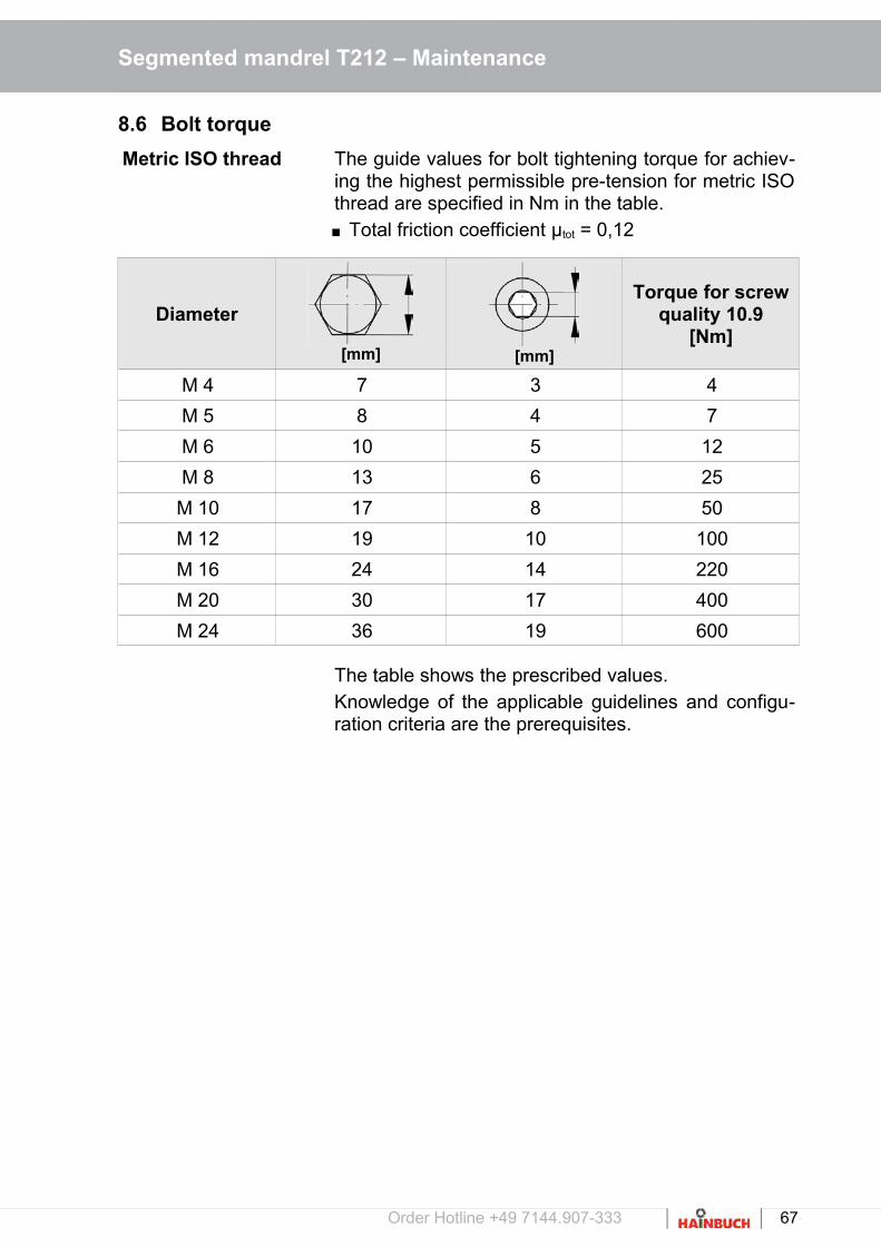
Segmented mandrel T212 – Maintenance
8.6 Bolt torque
Metric ISO thread The guide values for bolt tightening torque for achiev-ing the highest permissible pre-tension for metric ISOthread are specified in Nm in the table. Total friction coefficient μtot = 0,12
Diameter
[mm] [mm]
Torque for screwquality 10.9
[Nm]
M 4 7 3 4
M 5 8 4 7
M 6 10 5 12
M 8 13 6 25
M 10 17 8 50
M 12 19 10 100
M 16 24 14 220
M 20 30 17 400
M 24 36 19 600
The table shows the prescribed values.Knowledge of the applicable guidelines and configu-ration criteria are the prerequisites.
Order Hotline +49 7144.907-333 67

Segmented mandrel T212 – Trouble shooting
9 Trouble shooting
Possible fault causes and the tasks to correct thesefaults are described in the following section.If faults occur more frequently, the maintenance inter-vals must be shortened to correspond to the actualsystem load.Contact the manufacturer if there are faults that can-not be corrected by following the instructions below;see the service address on the back of this operatinginstruction.
9.1 Safety
Trouble shooting The following always applies:9. xx
1. For faults that pose a direct danger for personnel and or property immediately execute the emergen-cy-stop function of the machine.
2. Determine the cause of the fault.3. If correction of the fault requires work in the danger
zone, put the machine in set-up mode.4. Immediately inform the responsible parties at the
installation site of the fault.5. Depending on the type of fault, either have autho-
rized specialized personnel correct the fault, or correct it yourself.
The trouble shooting table provided below listspersonnel who are authorized to correct thefault.
6. If there is a fault that was not caused by the clamp-ing device the cause of the fault may be in the ma-chine area. See the operating manual for the ma-chine in this regard.
68 Order Hotline +49 7144.907-333

Segmented mandrel T212 – Trouble shooting
9.2 Trouble shooting table
Fault Possible cause Fault correction Corrected by
Clamping device does not open or release stroke is insufficient
Fouling between the drawmechanism and the clamping unit
Remove the clamping unite, move the drawtube back andclean the coupling area [see section »Disassembling the clamping unit«].
Specialist
Dimensional deviation of the draw tube adapter
Check the dimensions of the draw tube adapter and correct them if necessary.
Specialist
Clamping forceis too low
Work piece is over-dimen-sioned
Replace with a suitable clamping unit
Specialist
Insufficient hydraulic pressure on the clamping cylinder
Check the machine side hydraulic aggregate
Hydraulic specialist
Defective clamping cylinder or blocked draw tube
Contact the machine manufacturer
Machine manufac-turer
Compression springs fatigued [at permanent tension]
Replace compression springs
Specialist
Eccentric dimensional deviation on the work piece
Concentricity error of the segmented mandrel
Check the concentricity at the taper of the segmented mandrel, correct if necessary[see section »Checking and adjusting the face run and the concentricity«].
Specialist
Dimensional deviation on the work piece
Contaminated coupling area
Clean the coupling area of the clamping device[see section »Cleaning«].
Specialist
Contaminated clamping taper
Disassemble the clamping unit and clean the clamping taper[see section »Cleaning«].
Specialist
Formal defect on the work piece
Elastic deformation of feedstock that is subject to formal defects. After machining the workpiece returns to its original form.
Use feedstock with fewer formal defects.If technically justifiably reduce the clamping pressure.
Specialist
Order Hotline +49 7144.907-333 69

Segmented mandrel T212 – Trouble shooting
Fault Possible cause Fault correction Corrected by
Marks on the clamping surface
Point or linear work piece clamping
Replace with a clamping unitthat has a smoother clamping surface
Specialist
Excessive dimensional difference between the work piece diameter and the clamping bore
Replace with a clamping unitthat has a suitable clamping bore
Specialist
9.3 Start-up after corrected fault
After correcting the fault execute the following stepsto start up again:
7. xxx
1. Reset the emergency-stop device2. Acknowledge the fault on the machine tool con-
troller3. Ensure that no one is in the danger zone4. Start the machine tool
70 Order Hotline +49 7144.907-333

Segmented mandrel T212 – Appendix
10 Appendix
10.1 Service Hotline
Order Hotline
Quickly ordered and delivered. A call is all it takes:+49 7144. 907-333Schedule Hotline
Current status of your order? Just call:+49 7144. 907-22224h emergency call
Has there been a crash or other technicalemergency?Our experts are at your service around the clock:+49 7144. 907-444
10.2 Representatives
The sales partners and service employees listed be-low are available for further consultation or support.
10.2.1 EuropeAustriaHAINBUCH in Austria GmbHSPANNENDE TECHNIKPillweinstr. 165020 SalzburgPhone +43 662 825309E-mail: [email protected]: www.hainbuch.com
AustriaGGW Gruber & Co. GmbHKolingasse 61090 ViennaPhone +43 13107596-0Fax +43 13107596-31E-Mail: [email protected]: www.ggwgruber.com
BelgiumBIS Technics bvba/sprlZevenputtenstraat 203690 ZutendaalPhone +32 89518890Fax +32 89518899E-mail: [email protected]: www.bistechnics.com
Czech Republic,TMC CR s.r.o.Masná 27/960200 BrnoPhone +420 533433722Fax +420 548217219E-mail: [email protected]: www.tmccr.cz
DenmarkJørn B. Herringe A/SRamsømagleSyvvejen 314621 GadstrupPhone +45 46170000Fax +45 46170001E-mail: [email protected]: www.jbh-tools.dk
Estonia, Latvia, LithuaniaDV-Tools OÜPeterburi tee 34/411415 TallinnPhone +372 6030508Fax +372 6030508E-mail: [email protected]: www.dv-tools.ee
Order Hotline +49 7144.907-333 71

Segmented mandrel T212 – Appendix
FinlandOy Maanterä AbPL 70 Keinumäenkuja 201510 VantaaPhone +358 29006130Fax +358 290061130E-mail: [email protected]: www.maantera.fi
France HAINBUCH France SNCEquipements de machines-outilsZI Lons-Perrigny1600, Route de la Lième39570 Lons-le-SaunierPhone +33 384876666Fax +33 384876677E-mail: [email protected]: www.hainbuch.com
France Representative for: Haute SavoieUtilis France Sarl597, Avenue du Mont Blanc74460 MarnazPhone +33 450963630Fax +33 450963793E-mail: [email protected]: www.utilis.com
Great BritainHAINBUCH UK Ltd.WORKHOLDING TECHNOLOGY6 NewmarketKeys Business Village, Keys Park RoadHednesford, StaffordshireWS12 2HAPhone +44 1543 278731Fax +44 1543 478711Mobile +44 7980212784E-mail: [email protected]: www.hainbuch.com
GreecePAPET Papadopoulos GbRMartinstrasse 68DE-73061 Ebersbach/FilsPhone +49 71635858/530668Fax +49 716352265E-mail: [email protected]
HungaryGIMEX Hydraulik GmbHSelyem utca 1.9025 GyörPhone +36 96525588Fax +36 96427239E-mail: [email protected]: www.gimex.hut
IrelandHAINBUCH UK Ltd.WORKHOLDING TECHNOLOGY6 NewmarketKeys Business Village, Keys Park RoadHednesford, StaffordshireWS12 2HAPhone +44 1543 278731Fax +44 1543 478711Mobile +44 7980212784E-mail: [email protected]: www.hainbuch.com
Italy HAINBUCH Italia srlVia Caduti di Nassiriya 522036 Cantu [Co]Phone +39 0313355351Fax +39 031611570E-mail: [email protected]: www.hainbuchitalia.it
NetherlandsBIS Specials[Brandenburg Industry Service Dongen BV]Dreef 76996 BA DremptPhone +31 313482566Fax +31 313482569E-mail: [email protected]: www.bisspecials.com
NorwayOnstad Maskin A/SChr. H. Blomsgt. 133717 SkienPhone +47 35532373/74Fax +47 35532375E-mail: [email protected]: www.onstadmaskin.no
72 Order Hotline +49 7144.907-333
Segmented mandrel T212 – Appendix
PolandBIM Sp. z o.o.Złotniki, ul. Kobaltowa 662-002 Suchy LasPhone +48 616232041Fax +48 616232040E-mail: [email protected]
RomaniaBanatech srl. – connecting technologiesEp. Miron Cristea 26325400 Caransebes, Caras SeverinPhone +40 255517175Fax +40 355814125Mobile +40 749220553E-mail: [email protected]: www.banatech.ro
RussiaROSNA Engineering LLCSveaborgskaya street, 12, Letter »A«, office 20N,196105 Saint-PetersburgPhone +7 812 4016767Fax +7 812 4016767E-mail: [email protected]: www.rosna.spb.ru
SlovakiaNS s.r.o.Vácka ulica 4109/1001841 Dubnica N/VPhone +421 424450873Fax +421 424440406E-mail: [email protected]: www.tnssro.eu
SloveniaElmetool d.o.o.Prvomajska ulica 625000 Nova GoricaPhone +386 53303300Fax +386 53303304E-mail: [email protected]
Spain, PortugalATM S.LC/. Gran Bretanya, 16Pol. Ind. Pla de Llerona08520 Les Franqueses del Vallès [Barcelona]Phone +34 938700885Fax +34 938606572E-mail: [email protected]
SwedenHAINBUCH Svenska ABSPÄNNANDE TEKNIKKemistvägen 1718379 TäbyPhone +46 87327550Fax +46 87327650E-mail: [email protected]: www.hainbuch.com
SwitzerlandUtilis Müllheim AGPräzisionswerkzeugeKreuzlinger Strasse 22CH-8555 MüllheimPhone +41 527626262Fax +41 527626200E-mail: [email protected]: www.utilis.com
TurkeyHidkomOrganize Sanayi Bölgesi75. Yil CD. Demirciler Sit. B Blok No.216159 Nilüfer / BursaPhone +90 2242438292Fax +90 2242436365E-mail: [email protected]: www.hidkom.com
Order Hotline +49 7144.907-333 73

Segmented mandrel T212 – Appendix
10.2.2 AmericaArgentinaHAINBUCH America Corp.WORKHOLDING TECHNOLOGYW129N10980 Washington Dr.Germantown, WI 53022U.S.APhone +1 4143589550Fax +1 4143589560E-mail: [email protected]: www.hainbuchamerica.com
BrasilSSanposs TecnologiaSuprimentos e Consultoria Internacional Ltda.Rua Cândia n° 65 - Jardim do MarCEP: 09726-220São Bernardo do Campo - São PauloPhone +55 11 41266711Fax +55 11 41266710E-mail: [email protected]: www.sanposs.com.br
CanadaHAINBUCH America Corp.WORKHOLDING TECHNOLOGYW129 N10980 Washington Dr.Germantown, WI 53022U.S.APhone +1 4143589550Fax +1 4143589560E-mail: [email protected]: www.hainbuch.com
CanadaRepresentative for: Ontario, QuébecJ.Winkel & Associates Inc.6516 Warbler LaneL5N 6E1 Mississauga, OntarioU.S.APhone +1 4143589550Fax + 1 4143589560E-mail: [email protected]: www.hainbuch.com
MexicoHAINBUCH America Corp.WORKHOLDING TECHNOLOGYW129 N10980 Washington Dr.Germantown, WI 53022Phone +1 4143589550Fax +1 4143589560E-mail: [email protected]: www.hainbuch.com
USAHAINBUCH America Corp.WORKHOLDING TECHNOLOGYW129 N10980 Washington Dr.Germantown, WI 53022Phone +1 4143589550Fax +1 4143589560Se habla español:Tel +1 2143268081E-mail: [email protected]: www.hainbuch.com
10.2.3 AsiaChinaHAINBUCH Shanghai Co. Ltd.WORKHOLDING TECHNOLOGYRoom 611-612 BaoHong CenterNo. 7755 Zhongchun RoadMinhang District, Shanghai 201101Phone +86 2120916384Fax +86 2120916383E-mail: [email protected]: www.hainbuch.cn
IndiaM´la Sales Corporation5, YeshwantnagarTelco-Century Enka RoadPimpri, Pune 411018Phone +91 20 27477405Fax +91 20 27464249E-mail: [email protected]: www.mla-sales.com
IndiaA.H. RaoTechnical Consultant to HAINBUCHGround Floor, # 4157, 14th MainHAL 2nd Stage, IndiranagarBangalore 560 008Phone +91 8041463972Mobile +91 9986997959E-Mail: [email protected]
IndonesiaPT. STAHL ARBEITWTC Mangga Dua 2nd Floor A-6JL. Mangga Dua Raya No. 8Level 2 Blok C No. 41-45Jakarta 14430Phone +62 21 3777 6622Fax. +62 21 3001 8070E-mail: [email protected]: www.stahl-arbeit.com
74 Order Hotline +49 7144.907-333

Segmented mandrel T212 – Appendix
IsraelM.T.M. Machine Tools Marketing Ltd.26 Hakishor St.Holon 58867Phone +972 36479560Fax +972 36479578E-mail: [email protected]: www.mtm.co.il
JapanNK Works Co LTD2-17-17 Iwamoto-cho, Chiyoda-kuTokyo, 101-0032Phone +81 338645411Fax +81 338646752E-mail: [email protected]: www.nk-works.co.jp
KoreaKimi Co.B-101 98 Okgucheondongro Siheung-Si429-925 Gyeonggi-DoPhone +82 24137911Fax +82 24137910E-Mail: [email protected]
Malaysia, Singapore & VietnamJebsen & Jessen Technology [S] Pte Ltd.Process Engineering Division18 Enterprise RoadSingapore 629824Phone +65 63053692Fax +65 63053699E-mail: [email protected]: www.jjsea.com
TaiwanGSTC Technology Co., Ltd.No. 418, Youn-Chun East 1st RdTaichung City 40877, Taiwan'Phone +88 6423805678Fax +88 6423805511E-mail: [email protected]: www.gstctech.com.tw
ThailandHAINBUCH [ Thailand ] Co. LtdWORKHOLDING SOLUTIONS2/25 Sukhapiban 2 Road Prawet,Prawet, Bangkok 10250Phone +662329 0622/23Fax +662329 0624E-Mail: [email protected]: www.hainbuch.com
10.2.4 AustraliaAustraliaRomheld Automation Pty LtdUnit 30 115 Woodpark RoadSmithfield . NSW. 2164Phone +61 297211799Fax +61 297211766E-mail: [email protected]: www.romheld.com.au
10.2.5 AfricaSouth AfricaSouth Africa Retecon [PTY] Ltd.P.O. Box 14721620 Kempton ParkPhone +27 119768600Fax +27 113942471E-mail: [email protected]: www.retecon.co.za
Order Hotline +49 7144.907-333 75

Segmented mandrel T212 – Appendix
76 Order Hotline +49 7144.907-333
Segmented mandrel T212 – Appendix
IndexAAccessories.............................................
optional............................................23Assembly.................................................
Concentricity and face run............43f.Draw tube adapter.....................33, 59Flange..............................................34Preparations....................................30Segmented clamping bushing RD. .47Segmented clamping bushing SE...47Segmented mandrel [capteX B]......41Segmented mandrel [capteX]..........43Segmented mandrel [HSK].............36Segmented mandrel [machine spin-dle]...................................................38Work piece......................................50Work piece end-stop.......................48
BBolt torque...........................................67
CCheck...................................................21Cleaning...............................................62Control of the stroke position...............52
DDescription of variants...........................5Dimensional sheet...............................21Disassembly............................................
Flange..............................................58HYDROK.........................................58Segmented clamping bushing.........55Segmented mandrel [capteX B]......57Segmented mandrel [capteX]..........58Segmented mandrel [HSK].............56Segmented mandrel [machine spin-dle]...................................................56Work piece end-stop.......................55
Disposal...............................................60
EEnvironmental protection.....................19
GGrease.................................................24
IInspections...........................................51Installation................................................
Hydraulic segmented mandrel........45
Intended use........................................11
MMaintenance schedule.........................65
OOperating conditions............................20Overview..................................................
RD...................................................22SE / MAXXOS.................................23
PPackaging............................................27Personal protective equipment................
Hard hat...........................................12Protective gloves.............................13Protective goggles...........................13Protective work clothing..................12Safety footwear...............................12
Personnel requirements......................10Power specifications............................21Preservation.........................................63
RRepresentatives.......................................
Africa...............................................75America...........................................74Asia..................................................74Australia...........................................75Europe.............................................71
SScope of delivery...................................8Segmented clamping bushing.............24Special dangers...................................13Storing.................................................28Structure..............................................22Symbols on the packaging..................25
TTransport inspection............................26Transport, inner company....................26Trouble shooting..................................68Trouble shooting table.........................69Type designation.................................21
UUnpacking............................................26
WWork piece end-stop............................24
Order Hotline +49 7144.907-333 77

Segmented mandrel T212 – Appendix
78 Order Hotline +49 7144.907-333

Segmented mandrel T212 – Appendix
EC Declaration of conformityEG-Konformitätserklärung im Sinne der EG-Richtlinie 2006/42/EG über Maschinen [Anhang II A] /EC Declaration of conformity according to EC directive 2006/42/EC on machinery [Annex II A]
Original-Konformitätserklärung / Translation of original declaration of conformity
Hersteller / manufacturer: HAINBUCH GmbH Spannende TechnikErdmannhäuser Straße 5771672 MarbachDeutschland
Diese Erklärung bezieht sich nur auf die Maschine in dem Zustand, in dem sie in Verkehr gebracht wurde; vom Endnutzer nachträglich angebrachte Teile und/oder nachträglich vorgenommene Eingriffe bleiben unberücksichtigt. Die Erklärung verliert ihre Gültigkeit, wenn das Produkt ohne Zustimmung umgebaut oder verändert wird.This declaration relates exclusively to the machinery in the state in which it was placed on the market, and excludes components which are added and/or operations carried out subse-quently by the final user. The declaration is no more valid, if the product is modified without agreement.Hiermit erklären wir, dass die nachstehend beschriebene MaschineHerewith we declare, that the machinery described below
Produktbezeichnung / product denomination:
Segmented mandrel T212
allen einschlägigen Bestimmungen der Maschinenrichtlinie 2006/42/EG entspricht.is complying with all essential requirements of the Machinery Directive 2006/42/EC.
Angewandte harmonisierte Normen / Harmonised Standards used: EN ISO 12100:2011-03 Sicherheit von Maschinen – Allgemeine Gestaltungsleit-
sätzeSafety of Machinery – Basic concepts
DIN EN 1550:1997 Sicherheitsanforderungen für die Gestaltung und Konstruktion von Spannfuttern für die Werkstückaufnahme /Safety requirements for the design and construction of work holding chucks
Bevollmächtigter für die Zusam-menstellung der technischen Unterlagen / The person authorized to compile the relevant technical document-ation:
HAINBUCH GmbH Spannende TechnikKonstruktionsleitungErdmannhäuser Straße 5771672 MarbachDeutschland
Marbach, 01 June 2015 Konstruktionsleitung / Head of engineering
Ort, Datum / Place, Date
Funktion / function of signatory
Order Hotline +49 7144.907-333 79

HAINBUCH GMBH · SPANNENDE TECHNIKPO Box 1262 · 71667 Marbach / Erdmannhäuser Straße 57 · 71672 Marbach · GermanyPhone +49 7144.907-0 · Fax +49 7144.18826 · [email protected] · www.hainbuch.com24h-Emergency call +49 7144.907-444
06.
201
5 P
art n
o.:
8000
1/0
111
_en
S
ubje
ct to
tech
nica
l mod
ifica
tions