installation manual - furuno usa · iii equipment lists standard supply *see the lists at the back...
TRANSCRIPT
Installation ManualMulti Function Display
Model MFDBB
SAFETY INSTRUCTIONS ............................................................................ i
SYSTEM CONFIGURATION ....................................................................... ii
EQUIPMENT LISTS.................................................................................... iii
1. MOUNTING............................................................................................ 11.1 Mounting the Control Unit.............................................................................................11.2 Mounting the Processor Unit ........................................................................................7
2. WIRING .................................................................................................. 92.1 Processor Unit Wiring...................................................................................................92.2 Control Unit Wiring .....................................................................................................14
3. SETTING UP THE EQUIPMENT ......................................................... 153.1 Setup for Single MFD in the Network .........................................................................163.2 Setup for Multiple MFDs in the Network .....................................................................30
PACKING LISTS...................................................................................... A-1
OUTLINE DRAWINGS............................................................................. D-1
INTERCONNECTION DIAGRAM ............................................................ S-1
www.furuno.com
All brand and product names are trademarks, registered trademarks or their respective holders.


i
WARNING Indicates a potentially hazardous situation which, if not avoided, could result in death or serious injury.
CAUTION Indicates a potentially hazardous situation which, if not avoided, may result in minor or moderate injury.
Warning, Caution Mandatory Action Prohibitive Action
SAFETY INSTRUCTIONSThe user and installer must read the appropriate safety instructions before attempting to installor operate the equipment.
WARNING CAUTIONGround the equipment to prevent electrical shock and mutual interference.
Observe the following compass safe distancesto prevent interference to a magnetic compass:
ELECTRICAL SHOCK HAZARDDo not open the equipment unless totally familiar with electrical circuits.
Only qualified personnel should work inside the equipment.
Turn off the power at the switchboardbefore beginning the installation.
Fire or electrical shock can result if the power is left on.
Be sure that the power supply is compatible with the voltage rating of the equipment.
Connection of an incorrect power supplycan cause fire or damage the equipment.
Standardcompass
Steeringcompass
MPU-001 1.45 m 0.90 m
MCU-001 0.55 m 0.40 m
DCU12 0.70 m 0.45 m
Use the proper fuse.
Use of an incorrect fuse may damage the equipment.
NOTICEThis unit cannot be used as an input signal toequipment that requires interval input andaccuracy such as an autopilot.

ii
SYSTEM CONFIGURATION
MONITORMU-155C/170C, etc.
VIDEO IN (CCD CAMERA, MAX. 4)
LINE OUT(SPKR, ETC.)
12-24 VDC*2
DISPLAY CONTROLUNIT DCU12
CONTROL UNIT MCU-001
AND/OR*3
HUB-101
GPS NAVIGATORGP-330B
AIS RECEIVER,HEADING SENSOR orEXTERNAL BUZZER
USB DEVICE(MOUSE, KYBD)
NMEA 2000(GP-330B, ETC.)
POWER SUPPLY UNITPSU-013*1
: Standard Supply: Optional Supply: Local Supply
*1 Required with DRS25A*2 See the table and figure below for configurations for the PSU and rectifiers. *3 Max. two units total
PROCESSOR UNITMPU-001
RADAR SENSORDRS4A/DRS6A/DRS12A/DRS25A
OR
RADAR SENSORDRS2D/DRS4D
FISH FINDER(DFF series, ETR-6/10N,
ETR-30N, FCV-1150)
Matrix for radar model, PSU and rectifiers
DRS2D/4D/4A/6A/12A
MPU-001
RU-1746B-2
DRS25A
PSU-013
DRS25A
PSU-013
Radar Model
PSU Rectifier for MFDBB
Rectifier for PSU
Rectifier for MFDBB+PSU
DRS2D Not required
RU-1746B-2
DRS4D
DRS4A
DRS6A
DRS12A
DRS25A PSU-013* RU-1746B-2 RU-3424
* Standard supply with DRS25A.
12-24 VDC*2
RU-1746B-2
12-24 VDC2
LINE IN (MIC, for future use)
DRS25ADRS4ADRS6ADRS12A
RU-1746B-2 RU-3424
JUNCTION BOX FI-5002
MPU-001 MPU-001
FAX-30FA-50

iii
EQUIPMENT LISTS
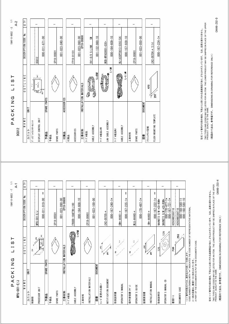
Standard supply
*See the lists at the back of this manual.
Optional supply
Name Type Code No. Qty Remarks
Processor Unit MPU-001 - 1
Control Unit MCU-001 - 1 Choose one.
Display Control Unit DCU12 - 1
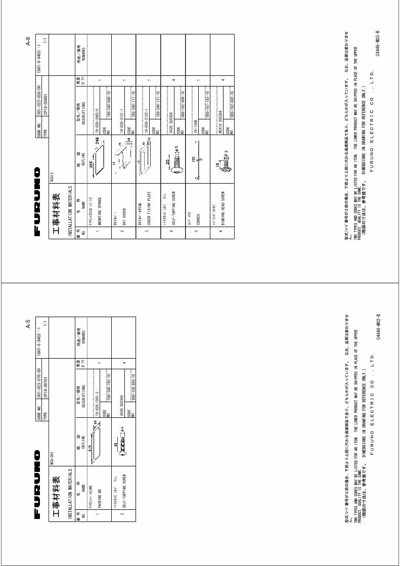
Installation Materials CP19-00600 000-011-664 1 set For MPU-001, Cable, CP19-00601*
CP19-00700 000-011-663 1 set For MCU-001, cable, CP19-00701*
Choose one.
CP19-00800 000-011-662 For DCU12, cables, CP19-00801*
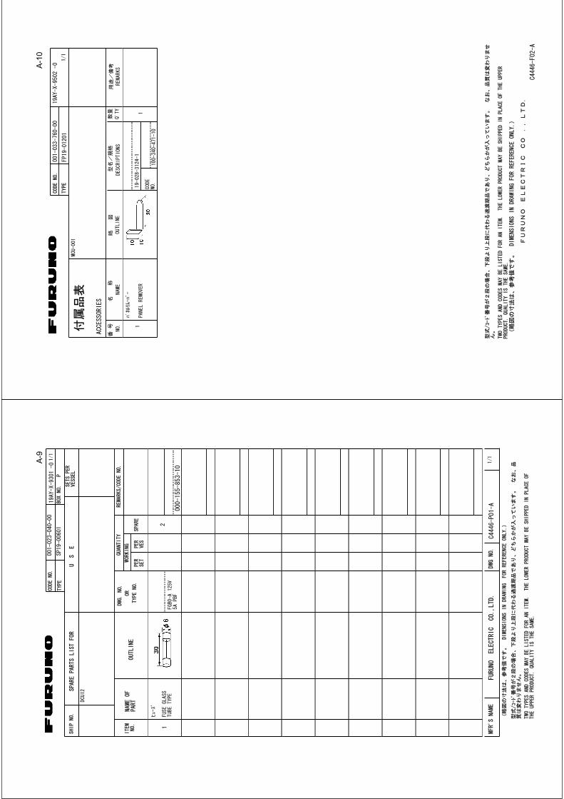
Spare Parts SP19-00501 001-023-090 1 set For MPU-001, fuses
SP19-00601 001-023-040 1 set For DCU-001, fuses
Accessories FP19-01201 001-033-760 1 For MCU-001, panel remover
FP19-01101 001-023-060 For DCU12, panel remover
Name Types Code No. Remarks
DVI-D Cable DVI-D/D SINGLELINK 000-149-054-10 5 m
DVI-D/D S-LINK 000-150-200-10 10 m
External Buzzer OP03-136 000-086-443
Rectifier RU-1746B-2 -
Network Hub HUB-101 -
Joint Box TL-CAT-012 000-167-140-10 For LAN cable extension
Junction Box FI-5002 000-010-765 For NMEA 2000
Control Unit MCU-001 -
Display Control Unit
DCU12 -

iv
Cable Assy MJ-A7SPF0007-050C 000-154-028-10 5 m, NMEA0183, w/7P connector
MJ-A6SPF0016-005C 000-159-689-11 For FAX-30, ETR6N/10N connection
MOD-Z072-020+ 000-167-175-10 2 m, LAN
MOD-Z072-050+ 000-167-176-10 5 m, LAN
MOD-Z072-100+ 000-167-177-10 10 m, LAN
MOD-Z073-030+ 000-167-171-10 3 m, for PC connection
M12-05BM+05BF-010 000-167-962-10 φ6, 1 m, NMEA 2000
M12-05BM+05BF-020 000-167-963-10 φ6, 2 m, NMEA 2000
M12-05BM+05BF-060 000-167-964-10 φ6, 6 m, NMEA 2000
M12-05BFFM-010 000-167-965-10 φ6, 1 m, NMEA 2000
M12-05BFFM-020 000-167-966-10 φ6, 2 m, NMEA 2000
M12-05BFFM-060 000-167-967-10 φ6, 6 m, NMEA 2000
CB-05PM+05BF-010 000-167-968-10 φ10, 1 m, NMEA 2000
CB-05PM+05BF-020 000-167-969-10 φ10, 2 m, NMEA 2000
CB-05PM+05BF-060 000-167-970-10 φ10, 6 m, NMEA 2000
CB-05BFFM-010 000-167-971-10 φ10, 1 m, NMEA 2000
CB-05BFFM-020 000-167-972-10 φ10, 2 m, NMEA 2000
CB-05BFFM-060 000-167-973-10 φ10, 6 m, NMEA 2000
NMEA connector LTWSS-050505-FMF-TS001
000-168-603-10 NMEA 2000 distributor (micro style)
LTWMC-05BMMT-SL8001
000-168-604-10 NMEA 2000 terminator, male (micro style)
LTWMC-05BFFT-SL8001
000-168-605-10 NMEA 2000 terminator, female (micro style)
LTWNC050505FMF-TS001
000-160-507-10 NMEA 2000 distributor (mini style)
LTWMN-05AMMT-SL8001
000-160-508-10 NMEA 2000 terminator, male (mini style)
LTWMN-05AFFT-SL8001
000-160-509-10 NMEA 2000 terminator, female (mini style)
In-line Terminator FRU-0505-FF-IS 000-172-037-10 NMEA 2000 connector w/terminator, micro style
Operator’s Manual OME-44460 000-167-217
NMEA 2000 Inter-face Unit
IF-NMEA2K1 -
Name Types Code No. Remarks

1
1. MOUNTING
1.1 Mounting the Control UnitThere are two types of control units: Control Unit MCU-001 and Display Control Unit DCU12. The former is the keyboard type, and the latter has an LCD display and keyboard.
When selecting a mounting location for the control unit, keep the following in mind:
• The temperature and humidity at the mounting location should be moderate and stable.• Locate the unit away from exhaust pipes and ventilators.• The mounting location should be well ventilated.• Mount the unit where shock and vibration are minimal.• Keep the unit away from electromagnetic field generating equipment such as motors and gen-
erators.• For maintenance and checking purposes, leave sufficient space at the sides and rear of the unit
and leave slack in cables. Minimum recommended space is shown on the outline drawing for the control units.
• Do not mount the DCU12 on the overhead.• A magnetic compass will be affected if the control unit is placed too close to it. Observe the
compass safe distances shown in the SAFETY INSTRUCTIONS to prevent disturbance to the magnetic compass.
• For the flush mount, make sure the mounting location is flat.

2
1.1.1 Mounting procedure for control unit MCU-001The control unit MCU-001 is designed to be flush mounted in a console or panel.
1. Prepare a cutout in the mounting location using the template sheet (supplied) for the MCU-001.
2. Remove the front panel from the MCU-001 by unfastening the catches at the rear of the panel, in the order as shown in the figure below.Note: Detach the panel carefully to prevent breakage of the panel.
3. Attach the mounting sponge to the MCU-001.4. Fix the MCU-001 by using four self-tapping screws (supplied).5. Attach the front panel to the MCU-001.
How to detach the front panel from the mounting place
To detach the front panel after mounting the unit, use the remover (supplied) as below. Do not attempt to remove it by any other method, to prevent damage to the unit.
1. Set the remover to the left-side notch at the bottom of the unit.
Mountingsponge
MCU-001
Cutout
Self-tapping screws(4 pcs.)
Front panel
1
2
3
4
5
6
MCU-001, rear view(Location of catches and order to unfasten them)

3
2. Pull the remover to raise the panel slightly.
3. Similarly use the remover to raise the panel at the right-side notch.4. Insert the remover to the space at the one end of the unit, and pull it to raise the panel slightly.
Repeat this procedure for the opposite side.
5. Use the remover to raise the panel at the two notches on the upper side of the unit.6. Use your hands to detach the front panel at both sides of it.

4
1.1.2 Mounting procedure for display control unit DCU12The Display Control Unit DCU12 can be flush mounted in a console or panel, or mounted on a desktop or the overhead.
Flush mounting
1. Prepare a cutout in the mounting location using the template sheet (supplied) for the DCU12.2. Remove the front panel from the DCU12 by unfastening the catches at the rear of he panel, in
the order as shown in the figure below.Note: Detach the panel carefully to prevent breakage of the panel.
3. Attach the mounting sponge to the DCU12.4. Fix the DCU12 by using four self-tapping screws (supplied).5. Attach the front panel to the DCU12.
How to detach the front panel from the mounting place
To detach the front panel after mounting the unit, use the remover (supplied) as below. Note that the front cover may be damaged if you do not follow the methods below.
1. Set the remover to a notch on the lower side of the unit.
Mounting sponge
Front panel
Cutout
Display unit(ex. MFD12)
Self-tapping screws(4 pcs.)
MFD, rear view(Location of catches and order to unfasten them)
1
2
3
4
5
6
7
1
8

5
2. Pull the remover to raise the panel slightly. Do this for all notches on the lower side of the unit.
3. Insert the remover to the space at the one side of the unit, and pull the remover to raise the panel slightly. Do the same for the opposite side.
4. Use your hands to detach the front panel from the lower side.

6
Desktop mounting
Follow the procedures below to mount the DCU12 on a desktop. This method requires the hanger.
1. Attach a liner to each side of the DCU12.2. Fix the hanger by using self-tapping screws (supplied).3. Screw knob bolts into the DCU12, set it to the hanger, and tighten the knob bolts.
DCU12
Hanger
Knob
Liner

7
1.2 Mounting the Processor Unit The unit can be mounted on the deck, a desktop or on a bulkhead. Select a mounting location considering the points below.
• Select a location where temperature and humidity are moderate and stable.• Consider the lengths of the cables connected among the processor unit, radar sensor and con-
trol unit.• For mounting on a bulkhead, be sure the mounting location is strong enough to support the unit
under the pitching and rolling normally encountered on the vessel.• Leave sufficient space around the unit for maintenance and servicing. Recommended mainte-
nance space appears in the outline drawing at the back of this manual.• A magnetic compass will be affected if the processor unit is placed too close to the magnetic
compass. Observe the compass safe distances in SAFETY INSTRUCTIONS to prevent distur-bance to the magnetic compass.
Desktop or deck mounting
Fasten with four self-tapping screws.
Processor unit, desktop/deck mounting
Self-tapping screw(6x30, 4 pcs.)

8
Bulkhead mounting
Mark four fixing hole positions on the bulkhead. Screw in two 6x30 self-tapping screws at upper fixing positions, leaving 5 mm protruding. Set the processor unit to the screws and screw in two self-tapping screws at lower positions. Tighten all screws.
Processor unit, bulkhead mounting
4 pcs.

9
2. WIRING
2.1 Processor Unit WiringFor detailed information about NMEA 2000 wiring, see “Furuno CAN bus Network Design Guide” (TIE-00170) on Tech-Net.
Note: Connect/disconnect cables after turning the power off.
Control UnitMCU-001 and/or DCU12
12-24 VDC
NMEA 0183 equipments(ex. GP-320B)
Radar Sensor or PSU-013
USB port*(Mouse, keyboard)
Display Control Unit DCU12or External display
(MU-155C/170C, etc.)
Video interfacedevices
External speaker*
NMEA 2000 equipment(SC-30, FI-50, GP-330B, etc.)
*: For USB, speaker and microphone connections, appropriate cables should be fastened to the metal plate beneath of connectors by the cable tie.
Metal plate
DPYC-6 cable(within 5 m)
2.5C2V or 3C2Vcoaxial cable
DVI-D/D SINGLELINK 5 m: supplied with DCU1210 m: option
MOD-Z072 cable5 m: supplied with MCU2 m, 10: option
7 pin: MJ-A7SPF0007 (5 m, option)18 pin: FRUDD-18AFFM (2 m, supplied)
Ship's ground
Ground cableIV-8sq.
CB-05BFFM, 1 m/2 m
MOD-ASW0001 cable(10, 15, 20, 30 m)
Network sounder, IP camera, etc.
MOD-WPAS cable (3 m)(supplied with DCU)
MOD-Z072 cable(2, 5, 10, 10 m)

10
POWER
Fabricate the power cable (DPYC-6 or equivalent) as shown below. Unfasten four pan head screws to remove the power terminal cover, and then connect the power cable DPYC-6 to the power terminal (upper: +, lower: -). Reattach the cover. The maximum cable length should be with-in 5 m.
ConductorS = 6 mmφ = 3.12 mm
2
DPYC-6
Armor
Sheath
φ = 15.2 mm
47 3
7
Armor
Cut the sheath.
Vinyl tape
Sheath
20
1Crimp-on lug (local supply)
20
Remove the paint.
5.5
8 to 12
Power terminal cover Power terminal
11
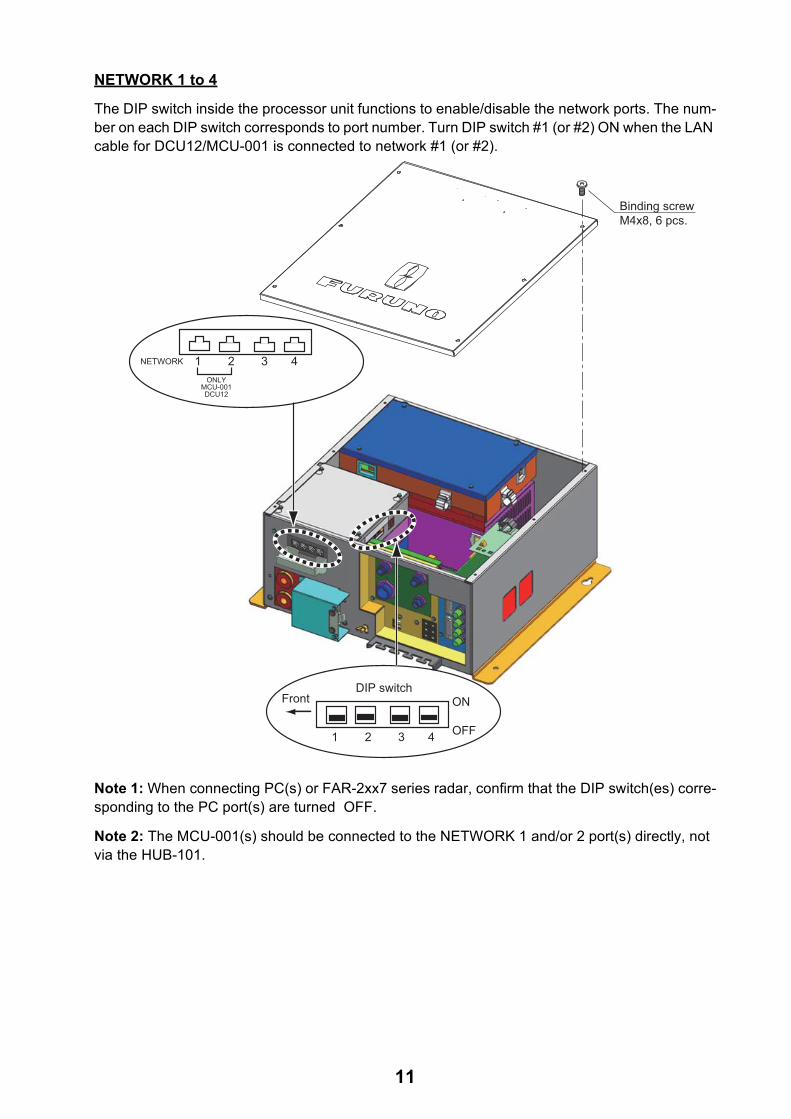
NETWORK 1 to 4
The DIP switch inside the processor unit functions to enable/disable the network ports. The num-ber on each DIP switch corresponds to port number. Turn DIP switch #1 (or #2) ON when the LAN cable for DCU12/MCU-001 is connected to network #1 (or #2).
Note 1: When connecting PC(s) or FAR-2xx7 series radar, confirm that the DIP switch(es) corre-sponding to the PC port(s) are turned OFF.
Note 2: The MCU-001(s) should be connected to the NETWORK 1 and/or 2 port(s) directly, not via the HUB-101.
DIP switchON
OFF
Front
1 2 3 4
NETWORK 1 2 3 4ONLY
MCU-001DCU12
Binding screwM4x8, 6 pcs.

12
Using DATA2 port (NMEA0183)
To connect multiple NMEA 0183 equipment, use the cable assy FRUDD-18AFFM-L180 supplied. This cable has an 18P connector. The DATA 2 port on the back of the processor unit. Solder wires of the FRUDD-18AFFM-L180 and the wires from sensors. The wire arrangement is shown below.
Pin No. Color Function Remark (Port No.)
18 Light green NET-C IN (0V) NMEA 2000 Power
17 Pink NET-S IN (+12V IN)
16 Purple Shield
15 White BUZZER or EVENT IN External buzzer or event switch
14 Gray SPEED-ALARM C Speed alarm contact
13 Yellow SPEED-ALARM H
12 Black/White +12V External buzzer power
11 Black GND
10 Blue/White RD3-C Port 3
9 Blue RD3-H
8 Green/White TD3-B
7 Green TD3-A
6 Orange/White GND
5 Orange GND
4 Brown/White RD2-C Port 2
3 Brown RD2-H
2 Red/White TD2-B
1 Red TD2-A

13
Video interface devices (analog type)
Maximum four camera/video devices can be connected. For this connection, the following cable is necessary (local supply).
• BNC connector• 3C2V (Japan Industrial Standard (JIS), or the equivalent) coaxial cable (impedance 75Ω)
3C-2V cable, sectional view
Video interface devices (digital type)
The NavNet 3D can display digital pictures from IP cameras (AXIS model 212 or 207 only) via LAN. IP addresses are allocated 172.31.200.003 through 006. For details, see the Operator’s Manual for model 212 and 207.
Insulator
Shield
Vinyl sheath
ConductorS = 0.19 mm = 0.5 mm
2

14
2.2 Display Control Unit WiringConnect the MOD-WPAS0001-030+ cable (from the processor unit) to the LAN connector at the rear of the display control unit. This cable has 3 m in length. If you need longer cable, use the op-tional joint box TL-CAT-012 and cable assy MOD-Z072 cable (2, 5 or 10 m). For DCU12, the con-nection of DVI cable is also necessary. When connecting this cable, follow the steps shown below for waterproofing.
1. Pass the DVI cable through the DVI cover (supplied) and fixing plate (supplied) in that order.2. Attach the DVI cable to the DVI connector at the rear of the DCU12, and then tighten the
thumbscrews on the connector.3. Slide the DVI cover so that it covers the connector at the rear of the display control unit.4. Put the fixing plate over the DVI cover, and then fasten it with four binding screws (supplied).5. Pass the cable tie (supplied) through two holes on the DVI cap, and fasten it tightly.
MCU-002,rear view
DVI cable
DVI cover
Fixing plate
Binding screw (M3X10)
MOD-WPAS0001-030+
Pass the cable tie through these holes, and fasten tightly.
MJ-A3SPF0013(power cable)

15
3. SETTING UP THE EQUIPMENT
This chapter shows you how to set up your system according to the equipment you have connect-ed. To do this more easily the Installation Wizard is provided. It has all the items necessary for setting up your system.
The Installation Wizard has four tabs, and each tab has some dialog boxes. You can construct your network system by setting these items in Wizard series.
Note: Do not transmit the radar until you have set up the radar sensor (on page 28).
Own tab
Set the NMEA 0183/2000 and Analog video devices connected to your MFD.
Global tab
Set data on the network. These data can be shared with MFDs on the network.
Sounder tab
This tab appears when a network sounder (DFF, ETR series) or FCV-1150 is connected. Set the items for frequencies and “TD-ID” transducer of Airmar as appropriate.
Radar tab
This tab appears when a radar sensor (DRS series) or FAR-2xx7 series (Ver. No.: 02.50 or before, type-C only) is connected. Set the antenna position and adjust the heading and main bang.
Used key on the Installation Wizard
A commercial USB mouse or keyboard can be used.
1 2
34
4
3
2
1
1 POWER key
RotoKey
Cursor pad
Left-click button
2
3
4

16
3.1 Setup for Single MFD in the NetworkWhen you have an MFD in the network, do the following procedures.
Language, DHCP server setting
1. Press the POWER key on the control unit to power the system. In a few minutes, the Installa-tion Wizard starts. After the system has confirmed sensors, the language selection screen appears. The default language is English. If you don’t need to change the language, click the [Next] button. If necessary, change language: choose the Select Language pull-down menu, and push the left-click button. Note that the language of the Installation Wizard is English regardless of language setting. And press the [Next] key.
The system counts the number of sounders, radars and other sensors you have connected and displays the results. Allow the system to count the number of sensors, which takes about 30 sec-onds.
The following menu appears.
2. Confirm that the Master (DHCP Server) pull-down menu shows ON, and press [Save and Exit] button to turn the power off.
3. Press the POWER key to turn on the equipment again.After the confirming sensors. the Master (DHCP Server) setting screen appears again.
4. Press the [Next] button to show the Own-Monitor tab.
English US
Save and Exit
29

17
Own-Monitor tab
5. If the MFDBB is fitted with dual monitors, choose Clone or Extended at the Dual Head mode pull-down menu as applicable and click the [Next] button. MPU-001 can output two picture data to the displays connected to DVI 1 and DVI 2 ports. You can choose how the picture data is shown on two displays at here. (When a monitor is connected, choose Clone.)Clone: Same picture is shown on two displays.
Extended: The picture is split to two screens as below. Left-side picture: Picture from the display connected to the DVI 1 port.Right-side picture: Picture from the display connected to the DVI 2 port.
6. Choose the DVI resolution of the display unit (Auto, SVGA, XGA or SXGA) at the DVI Resolution pull-down menu.
7. Click the [Next] button.
Dual Display mode setting SVGA XGA SXGAClone 800x600 1024x768 1280x1024Expanded 1600x600 2048x768 2560x1024
Picture from DVI1 port Picture from DVI2 port
Picture from DVI1 port Picture from DVI2 port

18
Own-NMEA 2000 tab
8. Check the PGNs (Parameter Group Number, NMEA 2000 messages) to output from the NMEA 2000 port, and click the [Next] button.
PGN No. and Messages
PGN No. Message mean126992 System Time127245 Rudder127250 Vessel Heading127251 Rate of Turn127257 Attitude127258 Magnetic Variation127259 Speed, Water referenced128267 Water Depth129025 Position, Rapid Update129026 COG & SOG, Rapid Update129029 GNSS Position Date129033 Time & Date129283 XTE129284 Navigation Data130306 Wind Data130310 Environmental Parameters130311129540 GNSS Sats in view129285 Navigation-Route/WP information130577 Direction Data

19
Own-NMEA 0183 port 1 through 3 tabs
Set up the NMEA0183 data ports.
NMEA0183 port 1: DATA1 connector (7 pins)NMEA0183 port 2: DATA2 connector (pin #: 1 to 4) NMEA0183 port 3: DATA2 connector (pin #: 7 to 11)
All NMEA0183 ports on your MFD are assigned respective nicknames. If you don’t like the preas-signed nickname, you can change it at Nickname field. Use the cursor pad to select location. Ro-tate the RotoKey to select character and push it to confirm selection. Repeat this operation to complete the nicknames
9. Set baud rate at the Baudrate pull-down menu, 4800 or 38400.10.Choose how to indicate waypoints, Name or ID No., at the WPT ID Format pull-down menu.11.Choose the pilot mode, Generic or Zeus, at the Pilot Mode pull-down menu.
• Generic: NAVpilot-500 or other auto pilot• Zeus: Mercury Zeus electronic steering
Note: When choosing Zeus at one of NMEA0183 ports (1 to 3), Generic is automatically set at the other ports.
12.At the L/L format dialog box, choose how many digits (seconds) to display after decimal point in latitude and longitude.
13.Choose the NMEA 0183 version to output, Ver 1.5, Ver 2.0 or Ver 3.0, at the Output format pull-down menu.

20
14.At the Output Sentences field, check the NMEA0183 sentences to output.
Note: If the Pilot mode is chosen to Zeus (at step 11), check APB, RMC, and XTE.15.At the Sensor Type field, check sensor data that is input to the MFD.
Example 1: Check Position & SOG/COG for GPS receiver connection.Example 2: Check Heading for heading sensor connection.When using the DATA2 and/or DATA3 ports on the MFD, set the NMEA0183 port 2 and/or port 3.
16.If the GPS receiver GP-320B is connected, click the [Advanced Setup] button to show the set-ting menu for GP-320B. Set all items referring to the table shown below.
NMEA0183 Output sentences
Name Meaning Name MeaningAAM Waypoint arrival alarm RMA Loran-C dataAPB Autopilot sentence RMBBOD Bearing origin to destination RMC GPS/TransitBWC/BWR Bearing and distance to waypoint VHW Speed/heading (through water)DBT Depth below transducer VTG Speed over ground, course (true)GGA GPS fix data WPL Waypoint locationGLL Geographic position (L/L) XTE Cross-track error, measuredGTD Geographical Position, Loran-C TDs ZDA Time and dateHDT Heading true ZTG UTC and time to destination waypointMTW Water temperature att Heading/Roll/Pitch
Basic Setup

21
17.Click the [Next] button.
Menu item Description
POS. Smoothing When the receiving condition is unfavorable, the GPS fix may change, even if the vessel is dead in water. This change can be reduced by smoothing the raw GPS fixes. A setting between 000 to 999 is available. The higher setting the more smoothed the raw data, however too high a setting slows response time to change in latitude and longitude. This is especially noticeable at high ship’s speeds. Increase the setting if the GPS fix changes.
SOG/COG Smooth-ing
During position fixing, ship’s velocity (speed and course) is directly measured by receiving GPS satellite signals. The raw velocity data may change ran-domly depending on receiving conditions and other factors. You can reduce this random variation by increasing the smoothing. Like with latitude and lon-gitude smoothing, the higher the speed and course smoothing the more smoothed the raw data. If the setting is too high, however, the response to speed and course change slows. For no smoothing, enter all zeroes.
Disable Satellite Every GPS satellite is broadcasting abnormal satellite number(s) in its Alma-nac, which contains general orbital data about all GPS satellites, including those which are malfunctioning. Using this information, the GPS receiver automatically eliminates any malfunctioning satellite from the GPS satellite schedule. However, the Almanac sometimes may not contain this information. If you hear about a malfunctioning satellite from another source, you can dis-able it manually. Enter satellite number (max. 3 satellites) in two digits.
INIT. Position Set initial latitude/longitude position for cold start.
ANT. Position Enter the GPS antenna positioning bow-stern and port-starboard position.
ANT. Height Enter the height of the GPS antenna unit above sea surface.
Rx Mode Choose position fixing method: 2D (three satellites in view), 2D/3D (three or four satellites in view whichever is greater).
WAAS Mode Select ON to use the WAAS mode.
WAAS Search WAAS satellite can be searched automatically or manually. For manual search, enter appropriate WAAS satellite number.
WAAS Alarm When the WAAS signal is lost, the audible alarm sounds one of two ways. On: Alarm sounds continuously until the WAAS positioning mode is available again or the alarm is acknowledged (by key operation). Off: Alarm sounds three times.
Origin

22
Own-Analog Video tab
18.Choose the signal format NTSC or PAL for the connected analog video equipment.All analog video equipment connected to the MFD are assigned respective nicknames (“PINP1 to 4”). If you don’t like the preassigned nickname, you can change it here. Use the cursor pad to select location. Rotate the RotoKey to select character and push it to confirm selection. Repeat this operation to complete the nicknames
19.Press the [Next] button.
Global-Boat tab
Enter your boat’s dimensions, length/width unit and engine’s specifications.
20.Choose the desired unit of length and width for the boat (ft, m) at the Length/Width/Height unit pull-down menu.
21.Set the length of boat at the Boat length pull-down menu.22.Set the width of boat at the Boat Width pull-down menu.23.Choose the number of engines on your boat (1, 2 or 3) at the Number of Engine pull-down
menu.24.Choose the max. scale of the tachometer (3000 rpm, 4000 rpm or 8000 rpm) at the Engine
Revolution pull-down menu.25.Choose the max. scale of the oil pressure meter (200kPa/2Bar/29Psi, 500kPa/5bar/72.5Psi or
1000kPa/10bar/145Psi) at the Max. Oil Pressure pull-down menu.26.Choose the max. scale of the boost meter (200kPa/2Bar/29Psi, 500kPa/5bar/72.5Psi or
1000kPa/10bar/145Psi) at the Max. Boost Pressure pull-down menu.27.Click the [Next] button.

23
Global-Nickname tab
All equipment in the NavNet 3D system are assigned respective nicknames. If you don’t like the preassigned nickname, you can change it here. Use the cursor pad to select location. Rotate the RotoKey to select character and push it to confirm selection. Repeat this operation to complete the nicknames. To update the nickname information on the network, click the [Refresh] button.
28.Click the [Next] button.
Global-IP Camera tab
The IP cameras connected to the network are assigned a name (“IPcamera1 to 4”). If you don’t like the preassigned name, you can change it here. Change the name using the cursor pad and RotoKey as is the Global-Nickname tab.
29.Click the [Next] button.

24
Global-Data Source tab
The Data Source dialog box shows the sources of various nav data. In case of multiple sensors for a nav data item, for example, several position-fixing equipment, choose the sensor to use, with the pull-down menu.
30.Click the [Next] button.When the GP-330B or WS-200 is connected to the NMEA2000 network, go to the GPS Mode. Set the WAAS, referring to the step 30. If not, go to step 31.
Item Description
Position & SOG/COG Choose the position-fixing sensor to use. (GP-320B, GP-310B, etc)
Heading Choose the heading sensor to use. (SC-30, PG-500, etc.)
Speed Through Water Choose the speed (STW) sensor to use. (DFF, etc.)
Water Depth Choose the depth sensor to use. (DFF, etc.)
Water Temperature Choose the temperature sensor to use. (DFF, etc.)
Wind Choose the wind sensor to use. (FI-303/501, WS-200, etc.)
Date & Time Choose the date and time source to use. (GP-320B, SC-30 etc.)
Roll and Pitch Choose the motion sensor to use. (SC-30, SC-50, etc.)
AIS Choose the AIS equipment to use. (FA-30/50/150 etc.)

25
31.The GPS Mode tub appears when the GP-330B or WS-200 is connected. Set the WAAS Mode and WAAS Search, and click the [Next] button. (See the list on page 21.)
Sounder, Radar tabs
Sounder
32. Click the Sounder Source select dialog box, and choose the type of the network sounder.
(Setting for DFF series)
a) Click the Transducer Setup pull-down menu, and choose Model Number, TD-ID or Manual, according to the transducer connected.Model Number: Furuno’s transducerTD-ID: Airmar’s transducer w/TD-IDManual: Transducers other than above
b) If you choose Model Number at step a), click the High Frequency and Low Frequency pull-down menus, and choose the applicable model type. For TD-ID and Manual, set the high and low frequencies.
c) For DFF1 or DFF1-UHD, click the Power pull-down menu, and choose output power of the transducer.DFF1: 1k(W) or 600WDFF1-UHD: 1k(W)
1.5 1.4
9.3 9.3
1.0 -0.8

26
d) If the satellite compass SC-30 or SC-50/110 is connected, set the distance between antenna unit (or sensor) of the satellite compass and transducer (high and low if con-nected) at the Transducer Position for SC pull-down menus.Bow-stern: Set the distance from antenna unit to the transducer in bow-stern direction. When the transducer is located on the fore side, set a positive value.Up-down: Set the distance from the transducer to the antenna unit in the vertical direction.Port-starboard: Set the distance from antenna unit to the transducer in port-starboard direction. When the transducer is located on the starboard side, set a positive value.
e) Click the Motion Sensor pull-down menu, and choose SC-30 or SC-50/110 if connected.f) Set the transducer position at the Transducer Position pull-down menus.
g) If the DFF3 is equipped with a water temperature sensor, click the Temperature Port pull-down menu, and choose the temperature source, MJ (NMEA0183 connector), High-freq(ency) or Low-freq(ency).
h) If a radar sensor is connected, click the Next button to continue.
Note: For DFF3, set the tap setting in the network sounder after setting up all the MFDs. For details, see the Operator’s Manual for DFF3.
SC-30
9.3 m
(Up-down)
1.5 m
(Bow-stern)
1.4 m
(Bow-stern)
High
Low0.8 m
1.0 m
SC-30 (Port-starboard)
Origin

27
(Setting for ETR)
a) Click the Transducer Setup pull-down menu, and choose Model Number or Manual, according to the transducer connected.Model Number: Furuno’s transducerManual: Transducers other than Furuno
b) If you choose Model Number at step a), click the High Frequency and Low Frequency pull-down menus, and choose the applicable model type. For Manual, set the high and low fre-quencies with the respective pull-down menus.
c) Use the arrow buttons at Transducer Position to set transducer position.
d) If a radar sensor is connected, click the Next button to continue.
(For FCV-1150)
Do the step c) shown above.
Origin

28
Radar
Set the Radar dialog box according to the radar connected.
33.Click the Radar Source select pull-down menu, and choose the radar type connected, DRS RADOME, DRS OPEN or FAR-2xx7.For “FAR-2xx7”, steps 32 through 35 shown below cannot be done. Set these items on the FAR-2xx7 radar.
34.Click the Antenna Height pull-down menu, and choose the height of the antenna above the waterline, among Under 10ft, 10ft-30ft or Over 30ft.
35.Do the heading adjustment as follows.You have mounted the radar sensor facing straight ahead in the direction of the bow. There- fore, a small but conspicuous target dead ahead visually should appear on the heading line (zero degrees).In practice, you will probably observe some small errors on the display because of the diffi-culty in achieving accurate initial positioning of the radar sensor. The following adjustment will compensate for this error.a) Set ship’s heading toward a suitable target (for example, ship or buoy). b) Click the Range pull-down menu, and choose a range between 0.125 and 0.25 nautical
miles.c) Click the [Push TX] button to transmit.
The radar picture appears on the right-half of the Radar dialog box.d) If necessary, adjust the gain, sea clutter and rain clutter using slider bars.
Place the cursor on the slider bar, and press the cursor pad while pressing the left-click but-ton.
e) Click the [-] [+] buttons for Heading Adjust to bisect the target with the heading line.f) As a final test, move the boat towards a small buoy and confirm that the buoy shows up
dead ahead on the radar when it is visually dead ahead.

29
36.If main bang appears at the screen center, click the [-] [+] buttons for MBS Adjustment so that the main bang disappears while watching the radar echo at the right-hand side of the display.
37.Click the [Radar Operation] button to adjust the tuning and video automatically.38.Click the [Save and Exit] button to finish the Installation Wizard.
Setting the zero line area (For DFF series only)
Turn the zero line (transmission line) on or off. When turned off, the line is not shown, which allows you to better watch fish echoes near the surface. The width of the line changes with transducer used and installation characteristics. If the width of the line is 1.0 m or more, set the line area as below.
1. At the normal operation mode, press the MENU key while pressing the CNTRL key down to open the Serviceman menu.
2. Rotate the Rotokey to choose the Fish Finder tab, and push the Rotokey.
3. Rotate the Rotokey to choose Zero Line Rejection, and push the Rotokey to turn the zero line on.The icon turns green color, and the cursor moves to Zero Line Range.
4. For DFF3, rotate the Rotokey to set the effective area (setting area: 1.0 to 2.0 m) and push the Rotokey. For DFF1 or DFF1-UHD, turn the zero line on or off.
5. Press the MENU key to close the menu.

30
3.2 Setup for Multiple MFDs in the NetworkWhen you have multiple MFDs in the network, designate one as the DHCP (dynamic Host Con-figuration Protocol) server.
1. Confirm that applicable DIP switches connected MFDs on the internal hub to ON.2. Turn on the MFD chosen to act as DHCP server.3. Select Language and click the [Next] button.The system counts the number of sounders, radars and other sensors you have connected and displays the results. Allow the system to count the number of sensors, which takes about 30 sec-onds.
4. Set Master (DHCP Server) setting to ON.5. Click the [Save and Exit] button. (The unit turns off automatically after one minute.) 6. Turn on the server MFD.7. Turn on all other MFDs in the network.8. Carry out the Installation Wizard settings on the master MFD, referring to section 3.1.9. Set up the next MFD as follows:
a) Press the POWER key to turn the power on.b) Choose language and click the [Next] button.c) Choose OFF from the Master (DHCP Server) setting box.d) Set up the MFD using the Installation Wizard, and wait for the other MFD’s setting are fin-
ished. 10.Set up other MFDs.11.After setting up all MFDs, click the [Save and Exit] button on the master MFD and the unit
goes off automatically.12.Click the [Save and Exit] button on other MFDs in the order in which they were set up.
The master MFD starts the normal application, and client MFDs go to the sleep mode, which is shows the no display though the power is turned on. The power LED lights orange.
13.Press the POWER key on the master MFD for three seconds to turn off the master MFD. Con-firm that other MFDs also are turned off.
14.Press the POWER key on master MFD. Confirm that the master MFD starts the normal appli-cation, and slave MFDs go to the sleep mode.To escape from the sleep mode to the normal mode, press the POWER key.
A-2
A-1

A-3
A-4
A-6
A-5

A-8
A-7
A-1
0A
-9

8/Aug/2012 Y.NISHIYAMA

Jun.27'07 R.Esumi

Oct.22'07 R.Esumi

Oct.22'07 R.Esumi

Mak
i電子署
名者 : Maki
DN: cn=Ma
ki, c=JP - 日
本, o=FURU
NO, ou=tec
hnicaldocu
ment, emai
l=hiromasa
.maki@furu
no.co.jp
日付 : 2013
.05.17 14:15
:30 +09'00'
S-1


The paper used in this manual
is elemental chlorine free.
・FURUNO Authorized Distributor/Dealer
9-52 Ashihara-cho,
Nishinomiya, 662-8580, JAPAN
A : APR 2008.Printed in JapanAll rights reserved.
D1 : FEB . 07, 2014
Pub. No. IME-44460-D1
(DAMI ) MFDBB
0 0 0 1 6 7 2 2 2 1 3