installation manual - forumbee · the following installation manual is intended for experienced and...
TRANSCRIPT

Installation Manual
By Firstech LLC, Version: 1.1
Applicable to the following remote start system: CM800-S – Auto Only Starter Control Module
This device complies with Part 15 of the FCC rules. Operation is subject to the following conditions; (1) This device may not cause harmful interference. (2) This device may accept any interference received, including interference that may cause undesired operation. CAUTION: Changes or modifications not expressly approved by the party responsible for compliance could void the user’s authority to operate this device.
WWW.COMPUSTAR.COM

2
Table of Contents Introduction ............................................................................................................................................ 3 Kit(s) Contents ....................................................................................................................................... 3 Installation Basics ................................................................................................................................. 4
Key Points to Consider Before Installation: .......................................................................................... 4 Remote Code Routine(s) ....................................................................................................................... 5 Placement and Use of Components ..................................................................................................... 5 Common Procedures ............................................................................................................................. 6
Valet Mode ........................................................................................................................................... 6 Jumper Settings ................................................................................................................................... 6 Tachless Sensing – Default Setting on Option 2-04 ............................................................................. 6 Alternator Sensing – Option 2-04 Setting 3 .......................................................................................... 7 Assumed Timed Crank – Option 2-04 Setting 4 ................................................................................... 7 Diesel Timer ......................................................................................................................................... 8 CM800-S Firmware .............................................................................................................................. 8
CM800-S Wiring Schematic (Remote Start) .......................................................................................... 9 Option Programming Tables ............................................................................................................... 13 Option Menu Descriptions .................................................................................................................. 14 Option Programming ........................................................................................................................... 17
Option Programming Using the FT-OP500-KIT .................................................................................. 17 Option Programming Using Compatible Remotes .............................................................................. 17
Troubleshooting ................................................................................................................................... 19 Remote Start Error Codes .................................................................................................................. 19 Frequently Asked Questions .............................................................................................................. 19
Technical Support Contacts ................................................................................................................ 21

3
Introduction
Thank you for purchasing a Firstech remote start system for your vehicle. The following installation manual is intended for experienced and authorized remote start technicians. This is not a tutorial on how to install. We highly recommend that you contact your local Firstech dealer and seek professional installation. Call 888-820-3690 or visit our website at www.compustar.com to locate your nearest dealer.
Caution: The Manufacturer’s warranty will be void if this product is installed by anyone other than an authorized dealer. Firstech reserves installation support services to authorized dealers only.
Kit(s) Contents
The CS8 Series Kits include all your basic components for basic install.
- 2 x Remotes - Starter Only Control Module CM800-S - 1 x Antenna - 1 x Hood Pin - Pack of Wiring Harnesses

4
Installation Basics If you are new to installing Firstech remote start units, we highly recommended that you review this manual in its entirety prior to installing your first unit.
Key Points to Consider Before Installation:
The two remotes are preprogrammed to the unit Page 5
This system is designed for ease of installation and the two included remotes are preprogrammed. In the event you may need to program new remotes cycle the ignition ON / OFF five times within seven seconds and tap the Lock button (half second) on the first remote, and then tap the Lock button (half second) on the second remote.
This system is only compatible with Automatic transmission vehicles
Unlike other Firstech remote start systems the CM800-S is only compatible with Automatic transmission vehicles. Manual transmissions are not supported by this unit.
New Valet Procedure Page 6
There are two amendments to Valet Mode. To place the system into Valet, you must hold the foot brake and cycle the ignition 5 times. To place the system into Valet using the remote you must turn the ignition on and then tap the Lock and Trunk buttons. System comes in Tachless Sensing Mode The CM800-S comes preprogrammed in No Tach Sensing Mode. You do not need to connect the Yellow/Black Tach/Alternator sensing wire to remote start the vehicle.
Tach learning procedure Page 6
To Learn Tach: STEP 1. Start the vehicle with the key and allow it to idle down STEP 2. Press and hold the foot brake STEP 3. While holding the foot brake, hold the remote start button on the remote for 2.5 seconds One parking light flash indicates that the vehicle tachometer signal has been successfully learned. Three parking light flashes indicate that the control module failed to learn the tachometer signal
New Option Menus Page 13
The new option menu differs completely from other Firstech systems. It is important to familiarize yourself with these as it will save time in most applications.
Option Programmer (OP500) Page 16
Most options on this unit can be programmed with the remote(s) as well as the Option Programmer (OP500). Please note the system must be disarmed before connecting the OP500. Otherwise, an “ERROR” message will show on the display of your OP500.

5
Remote Code Routine(s) IMPORTANT: The remotes are preprogrammed to the control module. In the event that you need to program the remotes follow the instructions below.
Programming the Remote STEP 1: Activate Programming mode by turning the ignition key on and off (between the Acc & On positions) five times within 10 seconds. The vehicle’s parking lights will flash once with the successful completion of this step. STEP 2: Within a second after cycling the ignition the 5th time, tap the Lock button on the remote for a half second. The parking lights will flash once to confirm the transmitter has been coded.
Programming Multiple Remotes: After the confirmation flash given in STEP 2, you can code additional remotes by tapping the Lock button on the remote(s). The parking lights will flash once confirming each additional remote. The CM800-S can store up to three remotes. Exiting Programming: Programming is a timed sequence. The parking lights will flash twice signaling the end of programming mode.
Placement and Use of Components IMPORTANT: The placement and use of components are critical to the performance of this system.
Antenna and Cable Firstech antennas are calibrated for horizontal installation at the top of the windshield. It does not have to be mounted in the top left corner as shown to the left. The cable that connects the antenna to the brain must be free from any pinches or kinks. Installing the antenna in areas other than the windshield may adversely affect the effective transmitting distance of the remotes.
Hood Pin The hood pin is an important safety feature that prevents the remote start from engaging while the hood is open. This is also to prevent accidental injury in the event that the vehicle is in service.
Antenna

6
Common Procedures
Valet Mode When servicing or loaning your vehicle to others, your remote start system should be placed in Valet Mode. Valet Mode prevents the system from remote starting and disables all alarm functions. IMPORTANT: While in Valet mode the remote start will still lock and unlock power lock systems.
The system can be put into valet one of two ways:
1. Turn the vehicle’s key to the ignition “on” position and tap the Lock and Trunk buttons simultaneously for a half second. The parking lights will flash once to confirm the system is in Valet Mode. Repeat this process to take the system out of Valet Mode. Ignition does not have to be on. Upon tapping the same buttons again the parking lights will flash twice to confirm the system is out of Valet Mode.
2. You can put the system into Valet by holding the foot brake and then turning the
ignition key “on” and then “off” five times within 10 seconds. The parking lights will flash once to confirm the system is in Valet Mode.
Jumper Settings Caution: Jumper settings affect the polarity and use of certain outputs. If these jumpers are used incorrectly, damage to the vehicle and control module may occur.
Jumper 1 (2nd Ignition / 2nd Starter / 2nd Accessory Relay)
This jumper determines the behavior of the large blue wire on Connector 1. This wire is powered by an internal relay in the control module. In the default position the jumper is set to 2nd Ignition. 2nd Ignition is common on GM and Toyota vehicles and will need powering. You can change the behavior of the wire to act as a 2nd Starter or 2nd Accessory to power up those wires common on newer Toyotas and Nissans.
Tachless Sensing – Default Setting on Option 2-04 Tachless sensing is an alternative engine sensing mode. Tachless sensing does not require a connection to the vehicle other than the main ignition harness. IMPORTANT: All wiring connections must be made before attempting remote starting. STEP 1: Connect all necessary wires. STEP 2: Process complete – there is no further programming required other than adjusting crank time when necessary (see below). Adjusting Crank Time: To adjust the crank times, refer to Options 1-03 and 2-05. To help ensure successful starting, the system will automatically add additional crank time to the 2nd and 3rd start attempts. In addition, there is a built in “Smart Resting Mode”. Traditional tach sensing is highly recommended for colder climates.
Tach Sensing – Option 2-04 Setting 2
Tach sensing mode requires a connection made with the yellow/black wire on Connector 2. Firstech recommends using an injector, coil or other tach source for tachometer sense. IMPORTANT: The tach must be programmed before remote starting. STEP 1: Start the vehicle with the key. Allow time for the engine to idle down.

7
STEP 2: Test wire and make connection. With the vehicle off the wire should test 0 Volts AC. At idle the tach wire should test between 1 to 5 Volts AC. As the vehicle RPM’s increase the voltage on the meter will also increase. Always solder tach connections. STEP 3: Learn tach. While the vehicle is at idle, hold the foot brake and press and hold the remote start button on the remote control for 2.5 seconds. The parking lights will flash once to confirm a good tach signal. The parking lights will flash three times to indicate the tach did not learn. Two seconds following the three flashes, the number of parking light flashes will indicate the cause of the error;
Alternator Sensing – Option 2-04 Setting 3 Alternator sensing is an alternative method the Firstech remote start system can utilize to determine if the engine is running. This is different than tachless sensing so the yellow/black wire connection must be made. IMPORTANT: No programming other than option changing is required for alternator sensing. STEP 1: Change Option 2-04 to setting 3 - Alternator Sensing. STEP 2: Test wire and make connection. The stator wire is found at the vehicles’ alternator. Change your meter to DC before testing for this wire. A. At rest, with the ignition off, the stator wire should test 0V DC. B. Turn the ignition to the run position. The stator wire should now test between 1 – 6V DC. C. Start the vehicle with the key. The stator wire should now test between 12 – 14V DC at idle. STEP 3: Process complete – no further programming is required.
Assumed Timed Crank – Option 2-04 Setting 4 Assumed Time Crank is the last feature of Option 2-04 for remote starting. This is intended for vehicles with built-in anti-grind feature or vehicles that do not have a 12V Positive starter wire at the ignition harness. This option will send a 3 second crank signal to the vehicle. This option can be used on vehicles with built in anti-grind systems.
Automatic Transmission Remote Start Function
Hold the button for 2.5 seconds to remote start an automatic transmission vehicle. If you are in range and if the vehicle is ready to remote start, the vehicle parking lights will flash once. If you are in range, the parking lights on the vehicle will flash three times followed by a certain number after that, there is a remote start error. Refer to the “remote start error diagnostic” table under the Troubleshooting section of this manual for details. Upon receiving confirmation that your vehicle is running, the parking lights will light solid. The remote start run time can be set for 3, 15, 25, or 45 minutes. The option is 1-08 to adjust the remote start run
Number of Parking Light Flashes
Tach Error
1 Option 2-04 is not on setting 2
2 Key is in the off position
3 Bad tach signal. Find a different wire.
8
time. This should be set at the time of installation. IMPORTANT: The vehicle’s key must be inserted into the ignition and turned to the “on” position prior to driving your vehicle. If the foot brake is depressed prior to the key inserted and in the “on” position, the vehicle will shut off.
Diesel Timer The CM800-S module has a built in Diesel Timer to allow the vehicle’s glow plug wire to heat up. There are two time settings on this unit, 7 or 18 seconds. This will allow the ignition to power up and then crank once the time has expired and glow plugs have properly heated up.
CM800-S Firmware
The CM800-S control module is firmware updatable through the internet. In the event Firstech makes any changes or corrections you can update the module using the RS232 port on the control module. This feature is a detailed process so please follow instructions on www.compustar.com.

9
CM800-S Wiring Schematic (Remote Start)

10
Connector 1 (CN1), 8-Pin Ignition Harness
Pin 1 Red - Constant 12V positive (+) power input. This wire must be connected. The proper vehicle
wire will test (+) 12V at all times - while the key is in the off position, the on position and during crank.
Pin 2 Green/White – This is the positive (+) parking light wire that triggers when you lock and unlock
the doors and remote start the vehicle. Pin 3 Red/White - Constant 12V positive (+) power input. This wire must be connected. The proper
vehicle wire will test (+) 12V at all times - while the key is in the off position, the on position and during crank.
Pin 4 White - Accessory 12V positive (+) output. This wire must be connected to the vehicle accessory
/ HVAC blower motor wire. The proper wire will test 0V with the key in the off position, (+) 12V while key is in the on position, 0V while cranking and back to (+) 12V when the key is returned to the on position.
. Pin 5 Blue - Positive 12V (+) output that powers up during remote start. The behavior of this wire is
selectable by a jumper inside the control module. By default this wire powers up as a 2nd Ignition trigger. It is changeable to a 2nd Starter or 2nd Accessory.
Pin 6 Yellow - Starter 12V positive (+) output. This wire must be connected for remote start. The proper wire will test 0V with the key in the off position, 0V while the key is in the on position and (+) 12V during crank.
Pin 7 Green – Ignition 12V positive (+) output and input. This wire must be connected to the vehicles’
ignition for remote start and valet / remote programming. The proper wire will test 0V with the key in the off position, 12 V (+) while the key is in the on position and 12V (+) during crank.
Pin 8 Black - Ground negative (-) input. This wire must be connected to the vehicle’s ground.
Connector 2 (CN2), 12-Pin Harness
Pin 1 Green/White - Parking light 250mA negative (-) output. The proper wire will test (-) when the
parking light switch is in the on position. Pin 2 Red/Black – 2nd Starter 250mA negative (-) output. This output can be used to trigger a relay to
power a 2nd Starter wire on the vehicle – common on newer Toyotas and Nissans.
11
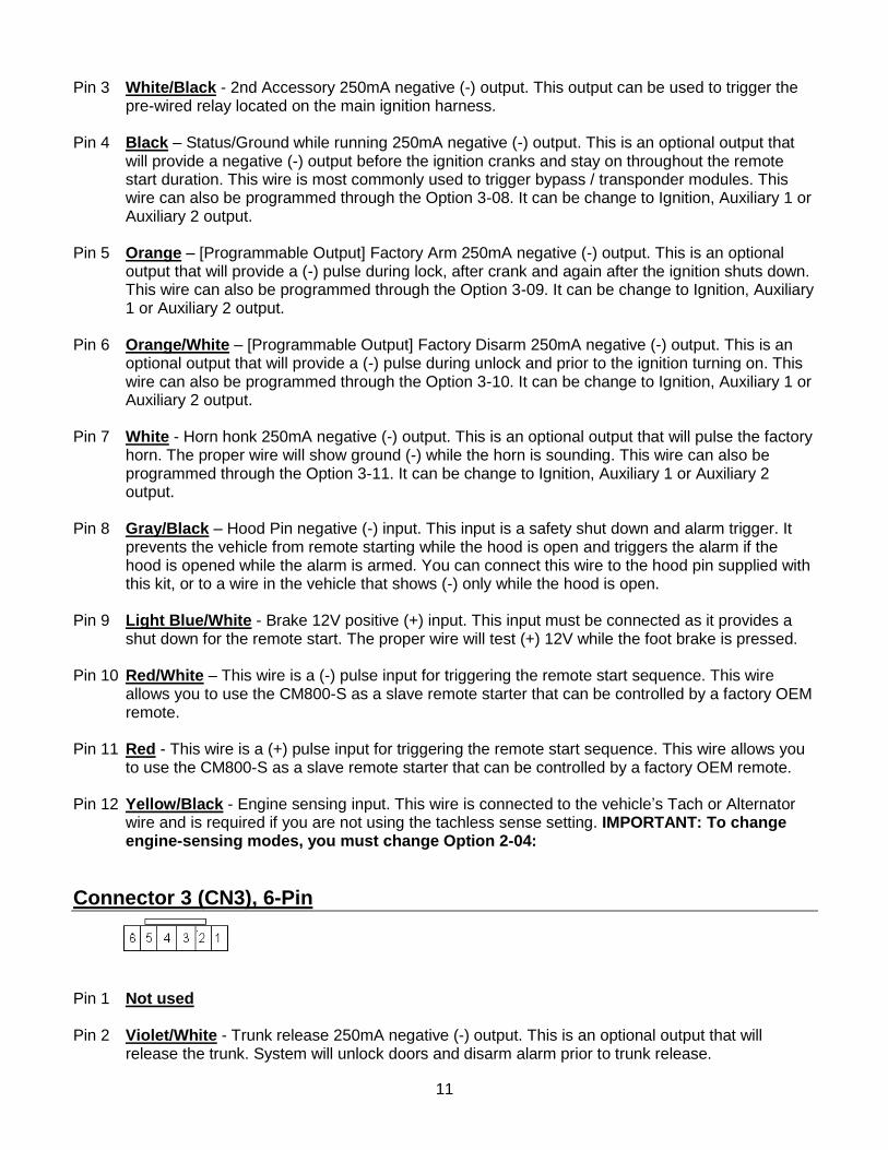
Pin 3 White/Black - 2nd Accessory 250mA negative (-) output. This output can be used to trigger the pre-wired relay located on the main ignition harness.
Pin 4 Black – Status/Ground while running 250mA negative (-) output. This is an optional output that
will provide a negative (-) output before the ignition cranks and stay on throughout the remote start duration. This wire is most commonly used to trigger bypass / transponder modules. This wire can also be programmed through the Option 3-08. It can be change to Ignition, Auxiliary 1 or Auxiliary 2 output.
Pin 5 Orange – [Programmable Output] Factory Arm 250mA negative (-) output. This is an optional
output that will provide a (-) pulse during lock, after crank and again after the ignition shuts down. This wire can also be programmed through the Option 3-09. It can be change to Ignition, Auxiliary 1 or Auxiliary 2 output.
Pin 6 Orange/White – [Programmable Output] Factory Disarm 250mA negative (-) output. This is an
optional output that will provide a (-) pulse during unlock and prior to the ignition turning on. This wire can also be programmed through the Option 3-10. It can be change to Ignition, Auxiliary 1 or Auxiliary 2 output.
Pin 7 White - Horn honk 250mA negative (-) output. This is an optional output that will pulse the factory
horn. The proper wire will show ground (-) while the horn is sounding. This wire can also be programmed through the Option 3-11. It can be change to Ignition, Auxiliary 1 or Auxiliary 2 output.
Pin 8 Gray/Black – Hood Pin negative (-) input. This input is a safety shut down and alarm trigger. It
prevents the vehicle from remote starting while the hood is open and triggers the alarm if the hood is opened while the alarm is armed. You can connect this wire to the hood pin supplied with this kit, or to a wire in the vehicle that shows (-) only while the hood is open.
Pin 9 Light Blue/White - Brake 12V positive (+) input. This input must be connected as it provides a
shut down for the remote start. The proper wire will test (+) 12V while the foot brake is pressed. Pin 10 Red/White – This wire is a (-) pulse input for triggering the remote start sequence. This wire
allows you to use the CM800-S as a slave remote starter that can be controlled by a factory OEM remote.
Pin 11 Red - This wire is a (+) pulse input for triggering the remote start sequence. This wire allows you to use the CM800-S as a slave remote starter that can be controlled by a factory OEM remote.
Pin 12 Yellow/Black - Engine sensing input. This wire is connected to the vehicle’s Tach or Alternator
wire and is required if you are not using the tachless sense setting. IMPORTANT: To change engine-sensing modes, you must change Option 2-04:
Connector 3 (CN3), 6-Pin
Pin 1 Not used Pin 2 Violet/White - Trunk release 250mA negative (-) output. This is an optional output that will
release the trunk. System will unlock doors and disarm alarm prior to trunk release.

12
Pin 3 Orange/Black – 2nd Pulse Unlock wire. This wire is used to provide the customer with a driver’s
priority unlock feature with option 1-04. With the option on the unlock (blue) wire will pulse first and then orange/black will pulse if the unlock button is pressed again within 3 seconds.
Pin 4 Blue - Unlock 250mA negative (-) output. This is an optional output that will provide a (-) pulse for
unlocking doors. System will unlock doors. IMPORTANT: You must use relays to reverse polarity for (+) trigger door lock systems.
Pin 5 Blue/Black - Lock 250mA (-) negative output. This is an optional output that will provide a (-)
pulse for locking doors. System will lock doors. IMPORTANT: You must use relays to reverse polarity for (+) trigger door lock systems.
Pin 6 Not used
Connector 4 (CN4), 4-Pin (RS232 Port)
This port provides simple connectivity to iDataLink bypass modules. This port supports 2-Way iDatalink protocol.
Connector 5 (CN5), 4-Pin (Pre-wired Antenna Cable)
Pin 1 Yellow - RX input. This wire receives the signal from remote. Pin 2 White - TX output. This wire transmits the signal to remote. Pin 3 Red – Constant 12V positive (+) output. Pin 4 Black – Negative (-) ground.
13
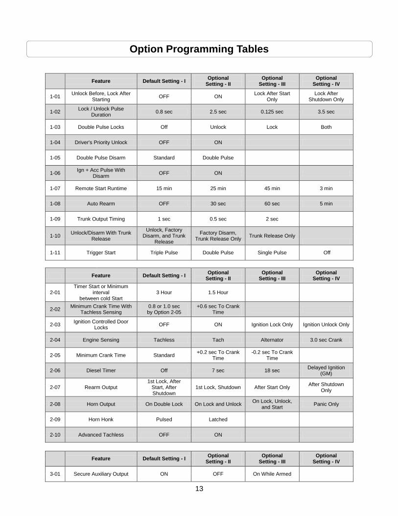
Option Programming Tables
Feature Default Setting - I
Optional Setting - II
Optional Setting - III
Optional Setting - IV
1-01 Unlock Before, Lock After
Starting OFF ON
Lock After Start Only
Lock After Shutdown Only
1-02 Lock / Unlock Pulse
Duration 0.8 sec 2.5 sec 0.125 sec 3.5 sec
1-03 Double Pulse Locks Off Unlock Lock Both
1-04 Driver's Priority Unlock OFF ON
1-05 Double Pulse Disarm Standard Double Pulse
1-06 Ign + Acc Pulse With
Disarm OFF ON
1-07 Remote Start Runtime 15 min 25 min 45 min 3 min
1-08 Auto Rearm OFF 30 sec 60 sec 5 min
1-09 Trunk Output Timing 1 sec 0.5 sec 2 sec
1-10 Unlock/Disarm With Trunk
Release
Unlock, Factory Disarm, and Trunk
Release
Factory Disarm, Trunk Release Only
Trunk Release Only
1-11 Trigger Start Triple Pulse Double Pulse Single Pulse Off
Feature Default Setting - I
Optional Setting - II
Optional Setting - III
Optional Setting - IV
2-01 Timer Start or Minimum
interval between cold Start
3 Hour 1.5 Hour
2-02 Minimum Crank Time With
Tachless Sensing 0.8 or 1.0 sec by Option 2-05
+0.6 sec To Crank Time
2-03 Ignition Controlled Door
Locks OFF ON Ignition Lock Only Ignition Unlock Only
2-04 Engine Sensing Tachless Tach Alternator 3.0 sec Crank
2-05 Minimum Crank Time Standard +0.2 sec To Crank
Time -0.2 sec To Crank
Time
2-06 Diesel Timer Off 7 sec 18 sec Delayed Ignition
(GM)
2-07 Rearm Output 1st Lock, After
Start, After Shutdown
1st Lock, Shutdown After Start Only After Shutdown
Only
2-08 Horn Output On Double Lock On Lock and Unlock On Lock, Unlock,
and Start Panic Only
2-09 Horn Honk Pulsed Latched
2-10 Advanced Tachless OFF ON
Feature Default Setting - I
Optional Setting - II
Optional Setting - III
Optional Setting - IV
3-01 Secure Auxiliary Output ON OFF On While Armed

14
3-02 Aux 1 Output 0.5 Second Latched 20 Seconds Program
3-03 Aux 2 Output 0.5 Second Latched 60 Seconds Program
3-04 Aux 1 Output Control By Remote Arm Disarm Ignition Off
3-05 Aux 2 Output Control By Remote Arm Disarm Panic
3-06 Horn Mute Control on
Remote Disabled Enabled
3-07 Sliding Door(Aux1, Aux2)
Control for iDatalink Modules
Off
Unlock, Factory Disarm,
and Sliding Door Control
Factory Disarm and Sliding Door Control
Only
3-08 CN 2 PIN 4 Status Ignition Aux1 Aux2
3-09 CN 2 PIN 5 Rearm Ignition Aux1 Aux2
3-10 CN 2 PIN 6 Disarm Ignition Aux1 Aux2
3-11 CN 2 PIN 7 Horn Ignition Aux1 Aux2
Special Option Group
Feature Setting Value (Seconds)
1 Aux 1 output 1- 99 seconds
2 Aux 2 output 1-99 seconds
IMPORTANT: System must be unlocked before you can set options with the OP500 or remotes.
*Once programmed, this feature requires activation from the remote. Please refer to the remote user manual or the option description below.
Option Menu Descriptions 1-01 Unlock Before, Lock After Starting - If enabled, this option will unlock the doors before remote
starting, start the vehicle, then lock the doors after the vehicle starts. It will then lock the doors again if the remote start run time expires and the vehicle shuts down. The third option locks the doors upon remote start shut down only. The fourth option turns on lock after remote start shutdown only. This feature is for vehicles that have factory alarms that need to be disarmed before remote starting such as Toyota and Lexus.
1-02 Lock / Unlock Pulse Duration – This option changes the length of the lock and unlock ground
pulses on the blue and blue/black wires on CN3. The default setting is for 0.8 seconds. Optional setting 2 changes the duration to a 2.5 second pulse. The third setting changes the duration to a short 0.125 second pulse setting. The fourth setting changes the duration to a 3.5 second pulse.
1-03 Double Pulse Locks – This option changes the behavior of both the lock and/or unlock wires.
This feature cannot be used with Option 1-04.

15
1-04 Driver’s Priority Unlock - The driver’s door must be isolated from the other doors. Use the Orange/Black CN3 as your 2nd Unlock output.
1-05 Double Pulse Disarm Wire – This feature turn the disarm wire into a double pulse output for
shutting down factory alarm outputs. 1-06 Ignition + Accessory Pulse with Disarm – This option will pulse the ignition and accessory
wires on CN1 at the same time the disarm wire pulses. Most new Ford vehicles need the ignition and accessory pulsed to disarm the factory alarm.
1-07 Remote Start Runtime – This option changes the remote start run time from its default 15
minutes to 25, 45, or 3 minutes. 1-08 Auto Rearm – This option will let you change when the vehicle will relock and rearm if the vehicle
is not started. 1-09 Trunk Output Timing – This option changes the output time of the violet/white wire on CN3. 1-10 Unlock/Disarm With Trunk Release – This option will change what the door locks will do upon
trunk release from the remote(s). 1-11 Trigger Start – This option changes the amount of pulse trigger(s) needed to active the control
module as a slave unit. The default setting requires three ground or 12V+ pulses to activate. Setting 2 changes the trigger to a double ground or 12V+ pulse. Setting 3 changes the trigger to a single ground or 12V+ pulse to activate the remote start sequence.
2-01 Timer Start or Interval Between Cold Start - This option dictates the time interval when the
control module will remote start.
Default 1: Will start every 3 hours until the vehicle is remote started or started by key and run for the set run time in option 1-08. Option 2: Will start every 1.5 hours until the vehicle is remote started or started by key and run time in option 1-08.
2-02 Minimum Crank Time With Tachless Sensing – This option will increase the standard crank
time from 0.8 seconds to 1.4 seconds when remote starting. Please keep in mind that the crank time will increase with each try.
2-03 Ignition Controlled Locks – When you turn this option on and have the power door locks
connected the doors will lock when you remote start or start the vehicle with the key and then press the foot brake. When you turn the key off the doors will unlock if this feature is turned on. The feature also requires activation from the remote. Simultaneously tap the Lock + Remote Start buttons for a half second to activate ignition controlled door locks from the remote. The parking lights will flash once to indicate this feature is ON.
2-04 Engine Sensing – This module comes default in Tachless mode where it does not require a
connection to a tach wire. Setting 2 changes to the tach sensing where you will need to connect to a wire that tests as a tach. Setting 3 changes the mode to Alternator sensing where you must connect a wire to the alternator’s stator wire. Setting 4 does an assumed start feature where the control module will automatically crank the yellow starter wire for 3 seconds. Please see the “Common Procedures” section on page 6-7 of this manual for complete explanations on the four engine sensing modes.

16
2-05 Minimum Crank Time - This feature applies to feature 2-02. It will add or remove crank time to the default setting of the afore mentioned option.
2-06 Diesel Timer – Use this option if you can’t find the glow plug wire. You can use setting 2 for a
default wait-to-crank; otherwise, you can adjust the time with your OP-500 Programmer. 2-07 Rearm Output – This option changes the events when the orange rearm output will pulse from
the control module. In the default mode the wire will pulse every time you lock, after remote start confirmation, and remote start shutdown. Setting 2 only pulses the wire upon lock and remote start shutdown. Setting 3 pulses the wire upon after remote start only. Setting 4 pulses the wire upon remote start shutdown only. Optional event to prevent factory alarm from triggering.
2-08 Horn Output – This feature changes when the white wire on CN2 will send a pulses. 2-09 Horn Honk - This feature will change the behavior of horn output (white wire CN2). 2-10 Advanced Tachless - This feature will provide an enhanced Tachless engine sensing mode.
3-01 Secure Auxiliary Output - This feature, in the default option should help prevent accidental
activation of the AUX outputs. 1 Way remotes require the user to hold trunk+start buttons for 2.5 seconds before activating AUX outputs Option setting II turns this feature off.)
3-02 Aux 1 Output - This option determines the duration of the Aux 1 output. Setting 4 allows the
output duration to be set for a specific length of time. 3-03 Aux 2 Output - This option determines the duration of the Aux 2 output. Setting 4 allows the
output duration to be set for a specific length of time. 3-04 Aux 1 Output Control – This option sets the condition which controls Auxiliary 1 and how it is
triggered. Please see the option table 3 for details. 3-05 Aux 2 Output Control - This option sets the condition which controls Auxiliary 2 and how it is
triggered. Please see the option table 3 for details. 3-06 Horn Mute Control On Remote – Enabling this option will allow the user to change the horn
mute on or off using their remote. 3-07 Sliding Door (Aux 1, Aux 2) Control for iDatalink Modules – This option changes the activity
of auxiliary 1 and 2 through iDatalink bypass modules only. 3-08 Connector 2, Pin 4 - This option will change the behavior of the black wire on Connector 2
(CN2). At default the wire will act as a status output but can be changed to (-) ignition, auxiliary 1 or auxiliary 2.
3-09 Connector 2, Pin 5 - This option will change the behavior of the orange wire on Connector 2
(CN2). At default the wire will act as a rearm output but can be changed to (-) ignition, auxiliary 1 or auxiliary 2.
3-10 Connector 2, Pin 6 - This option will change the behavior of the orange/white wire on Connector
2 (CN2). At default the wire will act as a disarm output but can be changed to (-) ignition, auxiliary 1 or auxiliary 2.
3-11 Connector 2, Pin 7 - This option will change the behavior of the white wire on Connector 2 (CN2). At default the wire will act as a horn output but can be changed to (-) ignition, auxiliary 1 or auxiliary 2.

17
Option Programming
How to Program Options There are two ways to set options on the CM8 control modules. You can use the FT-OP500-KIT or most
Firstech remotes. The remotes include 4 or 5 button 1 and 2 Way remotes.
Option Programming Using the FT-OP500-KIT The OP500 can be used to change anything in the Option Tables. It is required to change settings in the
Special Option Group.
STEP 1: Make sure system is unlocked/disarmed. Connect the antenna cable to the 4 or 6 pin port on
the top of the OP500. Once connected, the OP500 will power up as long as CN1 on the control module is
connected properly.
STEP 2: Use the left or right arrow keys on the OP500 to select option. Use the up or down arrow
buttons to select the option setting. “1” is the default setting, “2”, “3”, and “4” are the optional settings.
Special Option Group 1: Change the timed output of Auxiliary 1 and 2.
STEP 3: Hold the “W” (Write) button for 3 seconds. This finalize option changes to the control module.
Wait until OP500 displays “Success” before disconnecting.
To reset the options, hold the “R” (Reset) button and “W” (Write) buttons for 3 seconds. Then hold the
“W” button for 3 seconds.
Option Programming Using Compatible Remotes Using a remote is a timed process so review this section before beginning. Options cannot be
programmed with 1 button remotes. IMPORTANT: Special Option Groups cannot be programmed with
remotes – OP500 must be used.
STEP 1: Select the option you wish to program. Use the correct remote table below:
How to Program Options With 2 Way Remotes with Separate Lock and Unlock Buttons
Wa
it f
or
ch
irp
betw
een
eac
h
tap
Sc
roll T
hro
ug
h
Me
nu
(W
ait
fo
r
fla
sh
betw
een
eac
h t
ap
) W
ait
fo
r
co
rre
sp
on
din
g
park
ing
lig
ht
fla
sh
an
d/o
r
sir
en
ch
irp
befo
re s
ele
cti
ng
op
tio
n
Se
lec
t O
pti
on
1
Se
lect
Op
tio
n 2
Se
lec
t O
pti
on
3

18
Option Menu 1
Lock + Unlock for 3
seconds then Lock +
Unlock for 3 seconds
Tap Key
Button
Tap Lock
Button
Tap Unlock
Button
Hold Trunk
Button for 3
seconds
Option Menu 2
Lock + Unlock for 3
seconds then Lock +
Key for 3 seconds
Tap Key
Button
Tap Lock
Button
Tap Unlock
Button
Hold Trunk
Button for 3
seconds
Option Menu 3
Lock + Key for 3
seconds then Lock +
Unlock for 3 seconds
Tap Key
Button
Tap Lock
Button
Tap Unlock
Button
Hold Trunk
Button for 3
seconds
How to Program Options With 1 Way 4 Button Remotes
Wa
it f
or
ch
irp
betw
een
eac
h
tap
Sc
roll T
hro
ug
h
Me
nu
(W
ait
fo
r
fla
sh
betw
een
eac
h t
ap
)
Wa
it f
or
co
rre
sp
on
din
g p
ark
ing
lig
ht
fla
sh
an
d/o
r sir
en
ch
irp
befo
re s
ele
cti
ng
op
tio
n
Se
lec
t O
pti
on
1
Se
lec
t O
pti
on
2
Se
lec
t O
pti
on
3
Option Menu 1
Lock + Unlock for 3
seconds then Lock +
Unlock for 3 seconds
Hold Trunk +
Key for 3
seconds
Tap Lock
Button
Tap Unlock
Button
Tap Key
Button
Option Menu 2
Lock + Unlock for 3
seconds then Lock +
Key for 3 seconds
Hold Trunk +
Key for 3
seconds
Tap Lock
Button
Tap Unlock
Button
Tap Key
Button
Option Menu 3
Lock + Key for 3
seconds then Lock +
Unlock for 3 seconds
Hold Trunk +
Key for 3
seconds
Tap Lock
Button
Tap Unlock
Button
Tap Key
Button
STEP 2: Scroll through menu waiting for 1 parking light flash and/or siren chirp per line.
STEP 3: Once finished scrolling through menu, wait for the parking lights and/or siren chirp to confirm the option number. i.e. option 2-04 will flash and/or chirp 4 times. Select your option using the Lock, Unlock, Trunk, or Start buttons. Resetting to Factory Defaults: To reset the options in a particular menu, enter the menu using your
remote. To reset options with a 2 Way remote tap the Trunk button 3 three times. To reset options with a
1 Way remote tap the Start button 3 times. Wait for parking lights to flash and/or siren chirp between
each tap. After the third tap, the menu will reset back to default. This must be done for each option menu
that must be reset.

19
Troubleshooting
Remote Start Error Codes If the remote start fails to start the vehicle, the parking lights will flash three times immediately. Following those three flashes the parking lights will flash again corresponding to the error table;
Number of Parking Light
Flashes Remote Start Error
1 Motor running | or | must program tach before 1st remote start
2 Ignition on | or | foot brake on
6 Hood open
10 System is in Valet Mode
Frequently Asked Questions
I have everything hooked up and the system will not respond. A: Check all your wires to the control module. Next check your fuses and ground. If the system does not respond after that then try programming the remotes. Please see the “Common Procedure” section of this manual for remote programming instructions. Can I use any other Firstech remotes with this system?
A: Yes, the CM800-S control module is designed to only work with 4 Pin antennas and compatible remotes. It does not work with 6 to 6 Pin antennas.
I am trying to program options with the OP500 Option Programmer and it flashes “ER 01” when I plug it in to the antenna cable. What should I do?
A: First, make sure all connections are made to the control module. Second, make sure that the system is not locked. The last thing to check is the antenna cable or antenna extension cable – make sure this is not damaged. If you need to, try another cable. When the OP500 is working properly, it will read “Success Good.”
Is the CM800-S compatible with Manual Transmission vehicles? A: No, the CM800-S remote start system is compatible with Automatic Transmission vehicles only.
What is the thick blue wire on CN1 and the jumper in the control module? A: This wire is ran to an internal relay on the control module. This wire can be used to power up a 2nd Ignition, 2nd Starter, or 2nd Accessory wire on the vehicle. The behavior of the wire is changed by the internal jumper in the control module.
How do I set the auxiliaries?
20
A: The auxiliary outputs on this unit can be triggered via two analog wires or through a supported bypass module.
All my connections are made, how do I program the tach?
A: Start the vehicle with the key. Hold the foot brake down. While holding the foot brake down hold the Start button down for 3 seconds. If the system flashes the parking lights once then the tach is programmed. If it flashes three times, pause and then a certain amount please review the “Common Procedures” section of this manual.
The vehicle starts and shuts down 3 times in a row. A: This usually means that the engine sensing mode is not working correctly. If you are using a coil, change to an injector or try alternator mode. If you are using the tachless sensing mode and it does not start check the two power wire on the control module. If it does not remote start you may try setting 4 assume start otherwise the only alternative is finding a tach or alternator sense wire.
The vehicle will lock and unlock, but will not remote start or flash the parking lights. A: The system is in Valet Mode. Tap the Lock and Trunk Buttons and the same time for a half second to exit Valet Mode. If that does not work try reprogramming the remotes again. Do the door locks flip-flop in polarity? A: No. You can use the FT-DM-700 (relay pack) for high current positive (+) locks, or the FT-DM-600 harness used for low current 600mA positive (+) locks. If those are not available you must use two SPDT relays to invert the polarity.
.

21
Technical Support Contacts
Firstech technical support is reserved for authorized dealers only.
Monday - Friday 888-820-3690 (8:00 am – 5:00 pm Pacific Standard Time)
Email [email protected]
Web techfeed.compustar.com
Wiring Diagrams
Go to www.firstechonline.com to access Computech3. If you are an authorized dealer and unable to access this site please contact your sales rep or us call 888-820-3690 Monday through Friday, 8 am to 5 pm Pacific Standard Time.