installation manual for dlink+ w/cpdlc
TRANSCRIPT

INST-14114-1
Installation Manual for Dlink+ w/CPDLC
Document Number: INST-14114-1 Rev. D Page 1 of 55
Installation Manual for Dlink+ w/CPDLC
SLC Doc Number INST-14114-1
Revision D
12335 134th Court NE Redmond, WA 98052
USA Tel: (425) 285-3000 Fax: (425) 285-4200
Email: [email protected] RESTRICTION ON USE, PUBLICATION, OR DISCLOSURE OF PROPRIETARY INFORMATION
This document contains information proprietary to Spectralux Corporation, or to a third party to which Spectralux Corporation may have a legal obligation to protect such information from unauthorized disclosure, use, or duplication. Any disclosure, use, or duplication of this document or of any of the information contained herein for other than the specific purpose for which it was disclosed is expressly prohibited, except as Spectralux Corporation may otherwise agree in writing.
Preparer:
Engineer:
Program Manager:
Quality Assurance

INST-14114-1
Installation Manual for Dlink+ w/CPDLC
Document Number: INST-14114-1 Rev. D Page 2 of 55
CHANGE RECORD
Paragraph Description Of Change Approval/ Date
Revision
All Initial release L.Sinn 12/19/2011
- SVN
21090
3,4,5 Updated figures, added ARINC 429 time-information label requirement, generalized the post installation testing. Added section 5 and Appendix B PR-1603, PR-1689, ECO 11748
Paul Newby
11/27/12
A SVN
22176
2F, 2G PR-1722 Listed discrete specs. Corrected Figure 2-2 and 3-2 numbers to 2-1 and 3-1. Updated all screen shots of Configuration Loader. Added sections 5.7 & 5.8 to cover new Configuration Loader functionality.
Gary Altman Paul
Newby 09/12/13
B SVN
22868
4, Appendix B,C
Added Appendix C Aligned software instructions with the CCD. PR 1789, ECO-12103
Paul Newby
01/31/14
C SVN
23570
4.1.4 Added Personality Module connector pin layout Figure 4-1 PR 1789, ECO 12722
Jim Reynolds 08/03/15
D SVN
25655

INST-14114-1
Installation Manual for Dlink+ w/CPDLC
Document Number: INST-14114-1 Rev. D Page 3 of 55
Table of Contents 1 Introduction .............................................................................................................. 4
2 Description and Operation ...................................................................................... 4
3 Prepare for Installation ............................................................................................ 7
4 Installation and Test .............................................................................................. 13
4.1 Install the Dlink+ w/CPDLC System Components per the Referenced ACs: ..... 13
4.2 Loading the Configuration .................................................................................. 16
4.3 Installing the TSAP Database ............................................................................ 28
4.4 Testing the Installation ....................................................................................... 32
5 Configuration Loader Operation .......................................................................... 39
5.1 Network Setup ................................................................................................... 39
5.1.1 Windows TCP/IP Configuration ................................................................... 39
5.2 Reading the Configuration ................................................................................. 40
5.3 TSAP Database ................................................................................................. 40
5.3.1 Deleted ........................................................................................................ 40
5.3.2 Verifying the TSAP Database ...................................................................... 40
5.3.3 Erasing the TSAP Database ........................................................................ 41
5.4 Flash Memory .................................................................................................... 41
5.4.1 Reading the Flash Logs ............................................................................... 42
5.4.2 Erasing Flash Memory ................................................................................. 42
5.5 Loading Application Binaries.............................................................................. 42
5.6 Utilities ............................................................................................................... 43
5.6.1 Screen Dump to File .................................................................................... 43
5.6.2 Driving Output Discretes .............................................................................. 43
5.6.3 Getting the MOD Version ............................................................................. 44
5.6.4 Rebooting the Dlink+ w/CPDLC ................................................................... 44
5.7 Aircraft Addresses ............................................................................................. 45
5.8 Software Versions .............................................................................................. 45

INST-14114-1
Installation Manual for Dlink+ w/CPDLC
Document Number: INST-14114-1 Rev. D Page 4 of 55
1 Introduction A. This document provides the information required to install the following Dlink+
w/CPDLC part numbers, including all modification levels:
• 14114-1-XX “XX” designates the color of the Dlink+ w/CPDLC with a Keyboard Sub-Assembly (front panel). The only difference is the color of the front panel. Therefore, throughout this document, we refer to the Dlink+ w/CPDLC Part Number simply as 14114, except in the Environmental Qualification Form to indicate that 14114-1 was the exact model used for environmental testing. The information contained in this document applies to all color variants of the Dlink+ w/CPDLC.
B. For required test and repair instructions specific to the Dlink+ w/CPDLC, reference Spectralux Component Maintenance Manual 23-20-02. The instructions and procedures defined in the CMM are necessary to ensure the product operates satisfactorily over its service lifetime. Shop level repair is limited to replacement of Circuit Boards.
C. Spectralux Corporation contact information: 12335 134th Court NE, Redmond, WA 98052, USA
Telephone: +1 425-285-3000
Fax: +1 425-285-4200
Cage Code: 51896
D. The conditions and tests for TSO approval of this article are minimum performance standards. Those installing this article, on or in a specific type or class of aircraft, must determine that the aircraft installation conditions are within the TSO standards. TSO articles must have separate approval for installation in an aircraft. The article may be installed only according to 14 CFR part 43 or the applicable airworthiness requirements.
2 Description and Operation A. The Dlink+ w/CPDLC provides Aircraft Communication Addressing and Reporting
System (ACARS) and Controller Pilot Data Link Communications (CPDLC) message capability in one cockpit mounted Line Replaceable Unit (LRU). The Dlink+ w/CPDLC is a Class 7 transceiver that can be tuned to any 25 kHz channel over the frequency range of 118.000 to 136.975 MHz with an RF output power on all frequencies shall not be less than 10 watts in the air.
B. The Dlink+ w/CPDLC works in conjunction with a device called the “Personality Module” mounted separately. The Personality Module is a serial EEPROM that houses the unit’s configuration and database. When the unit is powered ON, the unit reads the data from the Personality Module. The configuration information determines the aircraft specific information such as tail number and the hardware configuration (i.e., what IO ports are connected and the type of devices connected to

INST-14114-1
Installation Manual for Dlink+ w/CPDLC
Document Number: INST-14114-1 Rev. D Page 5 of 55
those ports). The Personality Module is attached to the aircraft in which the Dlink+ w/CPDLC is installed and connects to the Dlink+ w/CPDLC when installed on the aircraft via the Dlink+ w/CPDLC 11 pin Mil-Circular connector. Any Dlink+ w/CPDLC that is connected to a given Personality Module will operate with the same configuration.
C. The Dlink+ w/CPDLC is cooled through its case and a rear mounted cooling fan. Under normal operating conditions no additional cooling is required.
D. Figure 2-1 is a perspective view of the Dlink+ w/CPDLC.
Figure 2-1 - Perspective View of Dlink+ w/CPDLC (14114 shown)
E. General Specifications
• DZUS Mount 5.75” W x 4.5” H x 8.71” D (14.6 cm W x 11.4 cm H 22.1 cm D)
• Weight: 5.1 pounds (2.3 kg)
• Operating Temperature: -15°C to +55°C
• Short Time Operating Temperature: -40ºC to +70ºC with reduced power output at greater than +55ºC
• Storage Temperature: -55°C to +85°C
• Environmental: DO-160E

INST-14114-1
Installation Manual for Dlink+ w/CPDLC
Document Number: INST-14114-1 Rev. D Page 6 of 55
F. Inputs
• 28 VDC (20.5 – 32.2 VDC), 25 watts standby, 160 watts transmitting
• RF (118 – 136.975 MHz)
• ARINC 429 Receivers: 8
• Discretes: 8 (Open / Ground) o Maximum guaranteed ground threshold: 3.5 V o Minimum guaranteed open threshold: 4.0 V o Typical source current when pulled to ground: 330 µA o Maximum resistance from input to ground to guarantee ground sensing:
100 Ω o Minimum resistance from input to ground to guarantee open sensing: 220
kΩ
• 10 Base-T Ethernet: 1
G. Outputs
• RF (118 – 136.975 MHz), 10 watts minimum
• ARINC 429 Transmitters 4
• Discretes: 4 (Open / Ground) o Maximum continuous applied voltage when in the open state: 35 V o Minimum applied voltage: 0 V o Maximum continuous sink current when in the ground state: 250 mA o Maximum inrush current, open to ground transition: 2.5 A, <10 ms
o Nominal output resistance: 7 Ω
• 10 Base-T Ethernet: 1

INST-14114-1
Installation Manual for Dlink+ w/CPDLC
Document Number: INST-14114-1 Rev. D Page 7 of 55
3 Prepare for Installation A. Installations must be performed per the requirements of FAA Advisory Circular (AC)
43.13-1B and 43.13-2B or later current revisions of these documents and any applicable documents referenced in these ACs. The ACs describe installation processes including how to locate the Dlink+ w/CPDLC, antenna requirements, wiring requirements, cable routing, mounting, circuit breaker information and other required steps. The ACs also include inspection steps and best practice guidance. Personnel who perform installations must be qualified and must meet all applicable FAA requirements.
B. The Dlink+ w/CPDLC is designed to fit into a standard, 5.75” (14.6 cm) by 4.5” (11.43 cm) Dzus rail mounting slot.
• There are two military circular connectors (one 11 pin connector and one 61 pin connector) and one RF TNC connector mounted to the rear of the unit. These connectors provide all input/output connections to the Dlink+ w/CPDLC. Tables 1 and 2 show the 11 pin and 61 pin connections.
• The ¼ turn Dzus fasteners are: Southco p/n: D5-PFSC35-38AZBB (default) –or– DFCI p/n: PFSC35-38AZBB.
C. Connections:
• The Dlink+ w/CPDLC RF output is a TNC connector that is used to connect to the coaxial cable running to an aircraft mounted VHF antenna. Use double-shielded coaxial cable RG400, or equivalent. The antenna will be vertically polarized and have a frequency range of 118.000-136.975 MHz. The antenna installation should conform to the applicable RTCA DO-224, Signal-in-Space Minimum Aviation System Performance Standards for Advanced VHF Digital Data Communications Including Compatibility with Digital Voice Techniques. The VHF Communication antenna must have a 50-ohm RF impedance with a maximum VSWR of 3:1. Maximum loss into the antenna must be less than 5.5 dB. The maximum VSWR presented to the Dlink+ w/CPDLC TNC connector must be 2:1 tested per RTCA DO-281.
• The 11-pin connector provides the power/ground, 5 Volt dimming bus, and Personality Module interfaces. The 11-pin connector mates with an MS3476L18-11S connector with appropriate strain relief. This mating connector uses #16 socket crimp contacts (M39029/5-116). Non-emergency +28 VDC aircraft power is routed to the connector. This power is provided using one or two 16 AWG wires. The wires are terminated with MS39029/5-116 contacts. The contacts are inserted into the connector’s “A” and/or “L” positions. If both “A” and “L” connector positions are used, they must be wired to the same power bus. A 7.5 amp circuit breaker must be used for protection.

INST-14114-1
Installation Manual for Dlink+ w/CPDLC
Document Number: INST-14114-1 Rev. D Page 8 of 55
The 28 VDC return (ground) is provided using one or two 16 AWG wire(s). The wires are terminated with MS39029/5-116 contacts. The contact is inserted into the connector’s “B” and/or “K” position. Chassis ground is connected using one 16 AWG wire into the connector’s “J” position. The Personality Module may be tie wrapped to the power cable or mounted to a nearby bulkhead. See installation instructions below.
• The 61-pin connector provides the unit’s signal interfaces. The 61-pin connector mates with an MS3476L24-61S connector. This connector uses #20 socket crimp contacts (M39029/5-115). Single wires for discretes and paired wires for ARINC 429 signals and for ethernet signals must be used. The unit was DO-160E qualified in two configurations. One configuration used shielded single wires and shielded twisted pairs with the shields attached to ground at both ends. Glenair backshells from the 40 series were used at the Dlink+ w/CPDLC for short termination of shields to chassis. The other configuration used unshielded single wires and shielded twisted pairs. The shields were grounded at both ends. At the Dlink+ w/CPDLC end, grounding was accomplished by connecting the shields to ground pins of the 61-pin connector. The cable was stabilized by a strain relief. To achieve passing RF emissions results with this configuration, it was necessary to install Quell Corp. 18-11.9 and 24-61.35 FilterSeals in J1 and J2, respectively. Other grounding and shielding schemes may be acceptable.

INST-14114-1
Installation Manual for Dlink+ w/CPDLC
Document Number: INST-14114-1 Rev. D Page 9 of 55
Table 1 - 11-Pin Connector Connections
11 Pin Military Circular Connections – Identifier – J1
Description Pin(s) +28V DC POWER A, L 28V DC RETURN B, K Personality Module CLOCK
C
Personality Module DATA D Personality Module +3.3V E Personality Module GND F Cockpit Dimming 5V G Cockpit Dimming COMMON
H
Chassis GROUND J
Table 2 - 61-Pin Connector Connections
61 Pin Military Connections – Identifier – J2 Description Pin(s)
Ground A, F, N, a, i, p, s, x, z, GG, KK
429 Transmit + Channel 1 AA Ethernet Transmit + B 429 Receive + Channel 8 b 429 Transmit - Channel 1 BB Ethernet Transmit - C 429 Receive - Channel 8 c 429 Receive + Channel 1 CC Ethernet Receive + D 429 Receive + Channel 7 d 429 Receive - Channel 1 DD Ethernet Receive - E 429 Receive - Channel 7 e 429 Receive + Channel 2 EE Not Used f 429 Receive - Channel 2 FF Output Discrete 1 - Chime G Input Discrete 7 g Output Discrete 2 – CPDLC Annunciator
H
Input Discrete 8 h

INST-14114-1
Installation Manual for Dlink+ w/CPDLC
Document Number: INST-14114-1 Rev. D Page 10 of 55
61 Pin Military Connections – Identifier – J2 Description Pin(s)
Not Used HH Input Discrete 1 j Output Discrete 3 – ACARS Annunciator
J
Not Used JJ Input Discrete 2 k Output Discrete 4 - Unused
K
Input Discrete 5 L Not used LL Input Discrete 6 M Not used m Not used MM Input Discrete 4 n Not Used NN 429 Transmit + Channel 2 P Not Used PP Not Used q 429 Transmit - Channel 2 R
T/ R TRIGGER (Factory test use only. Not used on aircraft)
r
429 Receive + Channel 3 S 429 Receive - Channel 3 T 429 Transmit + Channel 3 t 429 Receive + Channel 4 U 429 Transmit - Channel 3 u 429 Receive - Channel 4 V 429 Transmit + Channel 4 v 429 Receive + Channel 5 W 429 Transmit - Channel 4 w 429 Receive - Channel 5 X 429 Receive + Channel 6 Y Input Discrete 3 y 429 Receive - Channel 6 Z

INST-14114-1
Installation Manual for Dlink+ w/CPDLC
Document Number: INST-14114-1 Rev. D Page 11 of 55
D. Figure 3-1 provides the front, rear and side views.
E. Items required for installation will depend on the specific aircraft and situation. Installation items are not furnished by Spectralux. The following items are required and should be selected and installed per this document and the Advisory Circulars referenced above.
• Mounting hardware for Dlink+ w/CPDLC and Personality Module.
• Antenna with sealant.
• Cabling with proper connectors, routing and service loops.
F. A source providing the current time and date, via an ARINC 429 bus connection, must be supplied to the Dlink+ w/CPDLC. This time signal shall have a minimum resolution of one second. The time signal is generally label 150 (UTC) from the GNSS (GNLU or GNU), or ILS controller and the date signal is label 260. Note: the FMC label 260 is not adequate for a proper date signal, for this release, as the year is absent.
G. Installation approval - The conditions and tests required for TSO approval of the Dlink+ w/CPDLC and antenna are minimum performance standards. It is the responsibility of the installer to determine that the aircraft installation standards for a specific type or class of aircraft are in compliance with all applicable airworthiness standards. Installation in environments in excess of those listed in Appendix A is not permitted.
H. Before installation, perform a pre-modification avionics systems test to verify that the systems that will be connected to the Dlink+ w/CPDLC are working properly in accordance with their appropriate maintenance manuals.
I. Visually inspect the Dlink+ w/CPDLC packaging for evidence of shipping damage. Carefully unpack and inspect the Dlink+ w/CPDLC and associated equipment and verify all the items have been received. Reject any damaged items before beginning installation. Retain the shipping container and packaging materials in case reshipment or return to the supplier is necessary.

INST-14114-1
Installation Manual for Dlink+ w/CPDLC
Document Number: INST-14114-1 Rev. D Page 12 of 55
Figure 3-1 - Front, Side and Rear View (Dimensions in Inches)
J. The following items are required to configure the software on the newly installed Dlink+w/CPDLC: a. From the customer specific distribution with CCD prefix, copy the included
“Dlink_Configuration_Loader” folder and its contents to “C:\”. b. From the distribution of TF-14519-1, copy the TSAP database to the
“C:\Dlink_Configuration_Loader\” folder. The TSAP database will have a name similar to “CUST_TSAP_DB_PN_14230-3.bin”
c. PC Laptop and Ethernet cable. d. Aircraft specific information:
i. Aircraft Registration (Tail number, 7 chars max) ii. ICAO Address (6 characters)
iii. NSAP Address (40 characters) iv. Agency Code (2 chars)

INST-14114-1
Installation Manual for Dlink+ w/CPDLC
Document Number: INST-14114-1 Rev. D Page 13 of 55
4 Installation and Test 4.1 Install the Dlink+ w/CPDLC System Components per the Referenced ACs: 4.1.1 The Dlink+ w/CPDLC will be installed in available space in a standard 5.75” (14.6
cm) by 4.5” (11.43 cm) Dzus rails mounting slot after all cables have been routed and connected. Temporarily install in place and check for fit issues if necessary. Do not completely tighten installation hardware until all system components and cables have been installed.
4.1.2 VHF Antenna: If not already mounted, install the vertically polarized 118.000-136.975 MHz antenna. The antenna installation must conform to the applicable RTCA DO-224, Signal-in-Space Minimum Aviation System Performance Standards for Advanced VHF Digital Data Communications Including Compatibility with Digital Voice Techniques and must have a 50-ohm impedance with a maximum VSWR of 3:1.
Measure the distance from the antenna to the back of the Dlink+ w/CPDLC and plan for proper cable routing, securing and service loops.
Cut the RF cable to length and terminate one end of the cable with a TNC plug for connection to the Dlink+ w/CPDLC and the other end with the proper connector for attachment to the antenna.
Connect the RF cable to the 50-ohm interface on the antenna. Route the RF cable and verify the VSWR does not exceed 2:1, per RTCA DO-281, when measured from the Dlink+ w/CPDLC end. Connect to the RF TNC connection on the back of the Dlink+ w/CPDLC.
Ensure the antenna is properly sealed and the installation complies with the requirements of the referenced ACs.
4.1.3 Test mate samples of the proposed 11-pin and 61-pin connectors to the Dlink+ w/CPDLC to ensure compatibility.
4.1.4 Connect the 11-pin connector to provide power/ground, 5 Volt dimming bus, and Personality Module interfaces:
Mate the 11-pin connector to an MS3476L18-11S connector using #16 socket crimp contacts (M39029/5-116).
Route non-emergency +28 VDC aircraft power to the connector using one or two 16 AWG wires. Terminate the wire(s) with the MS39029/5-116 contacts and insert the contacts into the connector’s “A” and/or “L” positions. If two wires are used, both must be attached to the same power bus. Protect the circuit using one 7.5 amp circuit breaker per AC 43.13-1B.
Provide 28 VDC return (ground) using one or two 16 AWG wires. Terminate the wires using the MS39029/5-116 contacts and insert the contact into the connector’s “B” and/or “K” positions. The length of the wire should be kept as short as possible, but always less than 3 feet (1 meter).

INST-14114-1
Installation Manual for Dlink+ w/CPDLC
Document Number: INST-14114-1 Rev. D Page 14 of 55
The chassis ground is to be a 16 AWG wire in position “J”. The length of the wire should be kept as short as possible, but always less than 3 feet (1 meter).
The Personality Module is connected to the 11-pin connector by the Personality Module Cable Assembly PN 14315. The plastic connector (52054-1) is keyed to attach in only one way to the single 4 pin connector of the Personality Module. For reference, Figure 4-1 below shows pin 1 of the Personality Module end is identified with the orange wire.
PersonalityModule
11 – pinconnector
Pin 1
Pin 2
Pin 3
Pin 4
orange
wht
wht
wht
F
C
E
D
Figure 4-1 Personality Module to 11-pin
If the Personality Module is tie wrapped to the power cable, the wires are 24 AWG and should be no longer than 6 inches (15 cm). If the Personality Module is to be mounted on a nearby bulkhead then the wiring must be two pairs of twisted shielded pairs up to 3 feet (1 m) long. The +3.3V and Data lines should be in one pair and the GND and CLK should be in the other pair with the shields tied to the GND at both ends of the wire.
4.1.5 Connect the 61-pin connector to provide the unit’s signal interfaces:
Mate the 61-pin connector to an MS3476L24-61S connector using #20 socket crimp contacts (M39029/5-115).
The Ethernet pins are to be routed to a convenient bulkhead so there is easy access to the Ethernet socket. Use CAT5 cable or equivalent to connect from the 61-pin socket to the bulkhead RJ-45 socket and swap the transmit and receive lines so a standard Ethernet cable can be used to connect to a PC. Refer to Figure 4-2.

INST-14114-1
Installation Manual for Dlink+ w/CPDLC
Document Number: INST-14114-1 Rev. D Page 15 of 55
Figure 4-2 RJ-45 Connection
Refer to section 3C of this document for information about shielding.
4.1.6 Secure power cables and interconnecting cables and wiring. Ensure cables are
routed away from interfering areas on the aircraft, are protected from chafing and have required service loops per the referenced ACs.
4.1.7 Inspect the Dlink+ w/CPDLC system installation per the referenced ACs. 4.1.8 Complete the Dlink+ w/CPDLC system installation by tightening any temporarily
installed hardware.
INST-14114-1
Installation Manual for Dlink+ w/CPDLC
Document Number: INST-14114-1 Rev. D Page 16 of 55
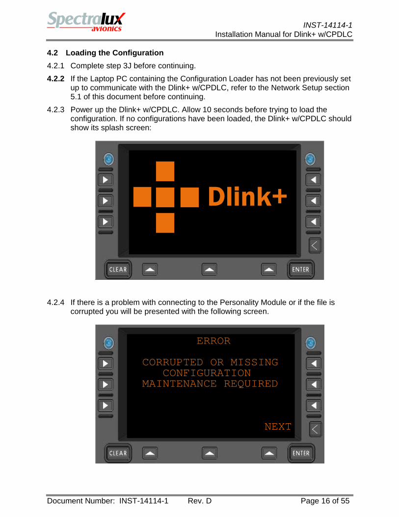
4.2 Loading the Configuration 4.2.1 Complete step 3J before continuing. 4.2.2 If the Laptop PC containing the Configuration Loader has not been previously set
up to communicate with the Dlink+ w/CPDLC, refer to the Network Setup section 5.1 of this document before continuing.
4.2.3 Power up the Dlink+ w/CPDLC. Allow 10 seconds before trying to load the configuration. If no configurations have been loaded, the Dlink+ w/CPDLC should show its splash screen:
4.2.4 If there is a problem with connecting to the Personality Module or if the file is
corrupted you will be presented with the following screen.
Dlink+
ERROR
CORRUPTED OR MISSING CONFIGURATION MAINTENANCE REQUIRED
NEXT

INST-14114-1
Installation Manual for Dlink+ w/CPDLC
Document Number: INST-14114-1 Rev. D Page 17 of 55
4.2.5 After ensuring the physical connection of the Personality Module to the Dlink+ w/CPDLC you can continue to update the configuration file.
4.2.6 Connect a Laptop PC containing the Configuration Loader software to the Ethernet connector.
4.2.7 Load the provided test or customer configuration as follows. 4.2.8 Start the Configuration Loader software.

INST-14114-1
Installation Manual for Dlink+ w/CPDLC
Document Number: INST-14114-1 Rev. D Page 18 of 55
4.2.9 Select the Configuration file. Click on Browse for Write Configuration and select the appropriate file. The configuration file is supplied by Spectralux and is customized for the installation.

INST-14114-1
Installation Manual for Dlink+ w/CPDLC
Document Number: INST-14114-1 Rev. D Page 19 of 55
4.2.10 Select Open. To write the file, click on Write Configuration.
4.2.11 The Dlink+ w/CPDLC will reboot after loading of the configuration is complete
and the screen should look as follows.
<ACARS CPDLC>
<FLT INFO MAINT>
NEXT

INST-14114-1
Installation Manual for Dlink+ w/CPDLC
Document Number: INST-14114-1 Rev. D Page 20 of 55
4.2.12 Enter the Aircraft Specific Information. The information may be entered through the Dlink+w/CPDLC menus by selecting MAINT>: or the aircraft addressing information can be entered using the Configuration Loader tool.
4.2.13 Enter Aircraft Specific Information using the Dlink+w/CPDLC menus.
4.2.13.1 Select CONFIG>:
MAINTENANCE MENU
<MONITOR CONFIG>
<SYS CNTRL SET UTC>
<RETURN FAIL STATUS>
CONFIG MAINTENANCE
USER EDIT>
SYS EDIT>
<RETURN VERSIONS>
NEXT

INST-14114-1
Installation Manual for Dlink+ w/CPDLC
Document Number: INST-14114-1 Rev. D Page 21 of 55
4.2.13.2 Select USER EDIT:
4.2.13.3 Enter the User Password (the default password is USER00) and press
ENTER.
4.2.13.4 Enter the above information. NOTE: The AC REG (SPECTR1) and ICAO ADDRESS (123456) are default entries in the configuration and are examples only.
PASSWORD
TYPE THE PASSWORD ANDPRESS THE ENTER KEY.
****** NEXT
EDIT CONFIG 1/5A AC REG ICAO ADDRESSSPECTR1 123456AVIONICS IND AC TYPE024 B737NAME---CUSTOMER--VERSION
A/B NEXT

INST-14114-1
Installation Manual for Dlink+ w/CPDLC
Document Number: INST-14114-1 Rev. D Page 22 of 55
4.2.13.5 Entered information first appears on the text entry line (just above A/B) and when all the text has been entered for a particular item, select that item.
For example, to enter the AC REG (Tail number), enter the following information.
4.2.13.6 Select the LSK labeled AC REG:
EDIT CONFIG 1/5AAC REG ICAO ADDRESSSPECTR1 123456AVIONICS IND AC TYPE024NAME---CUSTOMER—VERSION
MY4321 A/B NEXT
EDIT CONFIG 1/5AAC REG ICAO ADDRESSMY4321 123456AVIONICS IND AC TYPE024NAME---CUSTOMER—VERSION
A/B NEXT

INST-14114-1
Installation Manual for Dlink+ w/CPDLC
Document Number: INST-14114-1 Rev. D Page 23 of 55
4.2.13.7 Continue the process until all the required information is entered.
4.2.13.8 Press A/B to enter the NSAP address & Agency code.
EDIT CONFIG 1/5AAC REG ICAO ADDRESSMY4321 987654AVIONICS IND AC TYPE024 B737NAME---CUSTOMER—VERSIONCUSTOMER V1.0
A/B NEXT
EDIT CONFIG 1/5B
<UPLINK CFG ADDRESSES>
<USER EVENTS USER MSGS>
<RETURN
A/B NEXT

INST-14114-1
Installation Manual for Dlink+ w/CPDLC
Document Number: INST-14114-1 Rev. D Page 24 of 55
4.2.13.9 Select ADDRESSES.
4.2.13.10 Enter the 40-digit NSAP number; the first 20 digits are entered on
“NSAP 01-20” and the last 20 digits are entered on “NSAP 21-40”. See Appendix B for additional information about the format of the NSAP address. NOTE: There is a default entry that needs to be overwritten.
ADDRESS CONFIG AAC REG ICAO ADDRESSMY4321 987654 NSAP 01-2047002700000000000000 NSAP 21-4000000000000000000000
A/B NEXT
ADDRESS CONFIG AAC REG ICAO ADDRESSMY4321 987654 NSAP 01-2047002741678901009876 NSAP 21-4054000100000000000101
A/B NEXT

INST-14114-1
Installation Manual for Dlink+ w/CPDLC
Document Number: INST-14114-1 Rev. D Page 25 of 55
4.2.13.11 Press A/B after entering the 2nd NSAP line. 4.2.13.12 Enter the agency code.
4.2.13.13 Select RETURN:
ADDRESS CONFIG BAGENCY CODEXA
<RETURN
A/B NEXT
SAVE CONFIGURATION?
[YES ]
<RETURN
NEXT

INST-14114-1
Installation Manual for Dlink+ w/CPDLC
Document Number: INST-14114-1 Rev. D Page 26 of 55
4.2.13.14 Make sure L1 says YES, and select <RETURN. 4.2.13.15 The Dlink+ w/CPDLC will reboot. Loading of the Configuration is now
complete. The startup page will now appear as follows.
CUSTOMER V1.0
<ACARS CPDLC>
<FLT INFO MAINT>
NEXT

INST-14114-1
Installation Manual for Dlink+ w/CPDLC
Document Number: INST-14114-1 Rev. D Page 27 of 55
4.2.14 Enter Aircraft Specific Addressing information using the Configuration Loader tool: 4.2.14.1 Navigate to the “Aircraft Address” tab. 4.2.14.2 Enter the information as above. 4.2.14.3 When finished, press the Write button to commit the data to the
Personality Module.

INST-14114-1
Installation Manual for Dlink+ w/CPDLC
Document Number: INST-14114-1 Rev. D Page 28 of 55
4.2.14.4 The Dlink+ w/CPDLC will report that the configuration is being written to the Personality Module and reboot when complete. Loading of the Configuration is now complete. The startup page will now appear as follows:
4.3 Installing the TSAP Database The TSAP database needs to be loaded into the Dlink+ w/CPDLC’s flash memory at installation time. TSAP database functions are located on the “TSAP” tab of the Configuration Loader.
The TSAP database provides the Dlink+ w/CPDLC with addressing information required for the context management (CM) function when utilizing ATN. This database will be updated over time as the network is expanded or if specific addresses change. This process can be used for both a new installation and to upgrade the TSAP database.
CUSTOMER V1.0
<ACARS CPDLC>
<FLT INFO MAINT>
NEXT

INST-14114-1
Installation Manual for Dlink+ w/CPDLC
Document Number: INST-14114-1 Rev. D Page 29 of 55
4.3.1 Connect a Laptop PC containing the Configuration Loader software to the Ethernet connector. See section 5.1 Network Setup for further information.
4.3.2 Load the provided TSAP database as follows. 4.3.2.1 Start the Configuration Loader software.

INST-14114-1
Installation Manual for Dlink+ w/CPDLC
Document Number: INST-14114-1 Rev. D Page 30 of 55
4.3.2.2 Select the TSAP Database file: 4.3.2.3 The TSAP Database file is supplied by Spectralux and is customized
for the installation. To select the database click on Browse for the “Write TSAP Database” line and select the appropriate file.

INST-14114-1
Installation Manual for Dlink+ w/CPDLC
Document Number: INST-14114-1 Rev. D Page 31 of 55
4.3.2.4 Click on the Open button to select the file. Then click on the Write TSAP Database button to load the database into the Dlink+ w/CPDLC.
4.3.2.5 The Dlink+ w/CPDLC will reboot after loading of the TSAP Database is complete.
4.3.2.6 The Dlink+w/CPDLC screen should look as follows after the reboot:
<ACARS CPDLC>
<FLT INFO MAINT>
NEXT

INST-14114-1
Installation Manual for Dlink+ w/CPDLC
Document Number: INST-14114-1 Rev. D Page 32 of 55
4.4 Testing the Installation
Testing the installation will depend on the particular ground test procedure tailored to each specific airline and/or aircraft. Some generalized testing can be performed to provide an indication of the overall status of the Dlink+ w/CPDLC and attached systems.
4.4.1 Confirm the “FAIL” lamp is not lit. If it is lit, navigate to the Maintenance menu by
pressing the USER key, followed by MAINT> LSK, followed by FAIL STATUS> LSK. Make note of the message and contact an authorized Spectralux maintenance representative.
4.4.2 The status of each of the ARINC 429 transmitters and receivers can be
observed. Navigate to the Maintenance menu by pressing the USER key, followed by MAINT> LSK, <MONITOR LSK, and then NEXT LSK.
FAILURE STATUS
FAILURE DESCRIPTION:
* NO FAILURE *
<RETURN
NEXT
MONITOR 01:05:29 ATX1:OK TX2:--TX3:OK TX4:--RX1:-- RX2:OKRX3:OK RX4:NCRX5:-- RX6:--RX7:-- RX8:--
A/B NO COMM NEXT

INST-14114-1
Installation Manual for Dlink+ w/CPDLC
Document Number: INST-14114-1 Rev. D Page 33 of 55
“OK” – channel has valid activity
"NC” – channel has no valid activity
“- -“ – channel is not part of the system configuration. 4.4.3 The state of each of the OOOI inputs can be viewed from the monitor menu.
Navigate to the Maintenance menu by pressing the USER key, followed by MAINT> LSK, <MONITOR LSK, NEXT LSK, and then A/B LSK.
4.4.4 The resulting OOOI state inputs can be viewed on the Monitor menu, page 1B.
MONITOR 01:05:29 B BRAKES: 0 INHIB: 0 WOW1:0 WOW2:- WOW3:- WOW4:- WOW5:- WOW6:- DOR1:0 DOR2:0 DOR3:0 DOR4:- DOR5:- DOR6:-<RETURN
A/B NO COMM NEXT
MONITOR 01:05:29 BOOOI STATUS
WAITING FOR OUTDOORS OPENBRAKES UNSET
IN AIR<RETURN ALERTS INHIB:0
A/B NO COMM NEXT

INST-14114-1
Installation Manual for Dlink+ w/CPDLC
Document Number: INST-14114-1 Rev. D Page 34 of 55
4.4.5 Verify the OOOIs are operating by changing the state in maintenance mode on the aircraft and verifying they change correctly in the menu.
4.4.6 The current communication status can be viewed from page 1A of the monitor menu.
Possible Communication Statuses
VHF SATCOM ATN
“INOP” “AVAILABLE” “AVAILABLE”
“M2 AVAIL” “NO COMM” “UNAVAIL”
“MA AVAIL” “INOP” “INOP”
“NO COMM”
MONITOR 01:05:29 AFREQ STATUS SQP131.550 15COMM STATUS
VHF INOPSATCOM INOPATN INOP
A/B NO COMM NEXT

INST-14114-1
Installation Manual for Dlink+ w/CPDLC
Document Number: INST-14114-1 Rev. D Page 35 of 55
4.4.7 Two methods are available, from the system control menu, to transmit a message while not currently in comm. Navigate to the system control menu by pressing the USER key, followed by MAINT> LSK, and then <SYS CNTRL LSK.
4.4.8 The *LINK TEST key will send a link test message, while the *GROUND UTC
REQUEST key will send out a single request for the current time and date. 4.4.9 Ping Test Menus reside on the B page of the SYS CONTROL MSGS menu and
can be used to send a series of messages over the network to test connectivity. The Dlink+w/CPDLC must be in comm. before executing these functions.
SYS CONTROL MSGS A
*GROUND UTC REQUEST
*LINK TEST RADIO STATUS SET FREQ
A/B NEXT
SYS CONTROL MSGS BVOICE CONTACT REQUEST----------
<AVLC PING ACARS PING>
<RETURN
A/B NEXT

INST-14114-1
Installation Manual for Dlink+ w/CPDLC
Document Number: INST-14114-1 Rev. D Page 36 of 55
4.4.9.1 AVLC PING
NOTE: This function is deactivated in the CPDLC only configuration.
PAGE ITEM FUNCTION or DESCRIPTION
MSG COUNT How many test frames are to be sent.
DELAY SEC How many seconds to wait between test frame transmissions.
TEST CONTROL
Instructions to the test function.
Select from:
STOP, GO, WAIT, FAIL, HOLD
DELAY CNT Seconds to wait until the next transmission.
TEST FRM STATUS
Current testing status.
0 – Inactive
1 – Send message
2 – No Peer
3 – Not supported by peer
4 - Sending
AVLC PING TESTMSG COUNT DELAY SEC 0 0TEST CONTROL DELAY CNT[STOP ] 0TEST FRM STATUS0 SEC 0
NEXT

INST-14114-1
Installation Manual for Dlink+ w/CPDLC
Document Number: INST-14114-1 Rev. D Page 37 of 55
5 – Contact Made.
SEC Average response time in seconds.
<RETURN Return to previous page
4.4.9.2 AVLC PING
NOTE: This function is deactivated in the CPDLC only configuration.
PAGE ITEM FUNCTION or DESCRIPTION
MSG COUNT How many test frames are to be sent.
DELAY SEC How many seconds to wait between test frame transmissions.
TEST CONTROL
Instructions to the test function.
Select from:
STOP, GO, WAIT, FAIL, HOLD
DELAY CNT Seconds to wait until the next transmission.
SEC Average response time in seconds.
<RETURN Return to previous page
ACARS PING TESTMSG COUNT DELAY SEC 0 0TEST CONTROL DELAY CNT[STOP ] 0
<RETURN SEC 0
NEXT

INST-14114-1
Installation Manual for Dlink+ w/CPDLC
Document Number: INST-14114-1 Rev. D Page 38 of 55
4.4.10 Depending on the delivered configuration, it is possible that the ACARS or the CPDLC options have not been selected. If this is the case, upon selecting a menu or pressing a key associated with the non-selected option, one of these two screens will present:
NOTE: Selection of the ACARS and CPDLC configuration options can only be performed at the factory. If a change in the enabled function is desired, contact Spectralux.
ACARS FUNCTIONALITY IS NOT AVAILABLE
<RETURN
NEXT
CPDLC FUNCTIONALITY IS NOT AVAILABLE
<RETURN
NEXT

INST-14114-1
Installation Manual for Dlink+ w/CPDLC
Document Number: INST-14114-1 Rev. D Page 39 of 55
5 Configuration Loader Operation The Configuration loader, used in previous steps to load the configuration file, has additional capabilities. 5.1 Network Setup The TCP/IP network of the attached PC, which is running the Configuration Loader, must be configured to communicate with the Dlink+ w/CPDLC. The firewall program, if in use on the connected PC, must be configured to allow the Dlink+ w/CPDLC access. This is often accomplished by allowing it as an ‘exception’ in the System and Security settings. The Configuration Loader has been shown to be operational on Windows XP and Windows 7 personal computers. 5.1.1 Windows TCP/IP Configuration 1. Open Network Connections. 2. Right-click the network connection that you want to configure, and then
click Properties. 3. On the General tab (for a local area connection) or the Networking tab (for all other
connections), click the Internet Protocol (TCP/IP) component, and then click Properties.
4. On the General tab, click Obtain an IP address automatically. 5. On the Alternate Configuration tab, click User configured and then type
appropriate values for the following: • IP address
192.168.255.12
• Subnet mask 255.255.255.255.0
• Default gateway 192.168.1.0
• Preferred and alternate DNS server Blank
• Preferred and alternate WINS server
Blank
Note • To open Network Connections, click Start, click Control Panel, click Network and
Internet Connections, and then click Network Connections. • You must be logged on as an administrator or a member of the Administrators group
in order to complete this procedure. If your computer is connected to a network, network policy settings may also prevent you from completing this procedure.
Source (http://www.microsoft.com/resources/documentation/windows/xp/all/proddocs/en-us/sag_tcpip_pro_altconfig.mspx?mfr=true)

INST-14114-1
Installation Manual for Dlink+ w/CPDLC
Document Number: INST-14114-1 Rev. D Page 40 of 55
5.2 Reading the Configuration The configuration currently loaded onto the Dlink+ w/CPDLC can be retrieved from the Personality Module and stored to a binary file. This feature will allow customer modifications to be captured and forwarded to Spectralux for analysis if the need arises. This feature may also be useful to propagate customer modifications throughout their fleet. 5.3 TSAP Database The TSAP database needs to be loaded into the Dlink+ w/CPDLC’s flash memory at installation time. TSAP database functions are located on the “TSAP” tab of the Configuration Loader. The TSAP database provides the Dlink+ w/CPDLC with addressing information required for the context management (CM) function when utilizing ATN.
5.3.1 Deleted 5.3.2 Verifying the TSAP Database To verify the contents of a TSAP database loaded onto the Dlink+ w/CPDLC, the database must first be written then verified in a two-step process. First, use the Browse button to locate the TSAP database file to be compared against. The path and file name will appear in the associated text box. Press the Write TSAP Database button to commit the TSAP database; the Dlink+w/CPDLC will reboot after the write has completed. After the Dlink+w/CPDLC has reconnected to the configuration loader, press the Generate Dlink MD5 button. This action will read the TSAP database into

INST-14114-1
Installation Manual for Dlink+ w/CPDLC
Document Number: INST-14114-1 Rev. D Page 41 of 55
the loader, generate the MD5 checksum on it, and compare to the database that was just written.
5.3.3 Erasing the TSAP Database The existing TSAP database can be erased from the Dlink+ w/CPDLC by pressing the Erase TSAP Database button. This action is not recommended as a TSAP database is required for CPDLC operation. The process of updating the TSAP database will overwrite the currently installed database, replacing all previous entries. 5.4 Flash Memory Flash memory is non-volatile memory located on the Dlink+ w/CPDLC. Separate internal sections are used to store various operational informational logs and messages.

INST-14114-1
Installation Manual for Dlink+ w/CPDLC
Document Number: INST-14114-1 Rev. D Page 42 of 55
5.4.1 Reading the Flash Logs To read the stored messages log, first use the Browse button to select a path and file to save it as. The file path and name will appear in the associated text box and the Read Flash Logs button will become enabled once a valid target has been selected. Pressing the Read Flash Logs button will begin the process of downloading a 1 megabyte section of the flash memory to the attached PC. This will take several minutes and the progress will be displayed, replacing the text on the Read Flash Logs button. The raw memory, after it is downloaded, will be post processed to a human readable format and stored as the indicated target file. 5.4.2 Erasing Flash Memory The Erase Flash button will erase the sections of flash memory holding the message logs and any stored variables. This option will erase operational data and effectively place the Dlink+ w/CPDLC into a ‘new’ state. 5.5 Loading Application Binaries It is possible to update the applications that make up the Dlink+ w/CPDLC over the Ethernet connection. This operation should only be attempted by authorized Spectralux maintenance personal. The file names and encoded contents are set at the factory; the Configuration Loader will not attempt to load files that do not meet the specific requirements. The text of the Write button will be replaced with the progress of the load operation.

INST-14114-1
Installation Manual for Dlink+ w/CPDLC
Document Number: INST-14114-1 Rev. D Page 43 of 55
5.6 Utilities There are several utility functions included in the Configuration Loader to aid in the installation and possible troubleshooting of the Dlink+ w/CPDLC.
5.6.1 Screen Dump to File It is possible to capture the currently displayed Dlink+ w/CPDLC screen and save it to a file. First use the Browse button to select a path and file name. When a valid file is selected it will be displayed in the associated text box and the Dump Current Screen button will be enabled. This file is not human-readable and is meant to be decoded by an authorized Spectralux maintenance personnel. 5.6.2 Driving Output Discretes Using the proved buttons: Discrete Output 1, Discrete Output 2, and Discrete Output 3 it is possible to drive the output discretes for testing. The ‘next’ state or the desired action will be reflected on the button and will be updated with each press. The special testing mode must first be enabled by pressing the Discrete Testing Enable button. Driving the output discretes using the Configuration loader will prevent the operation of the input discretes. This is an expected side effect of placing the Dlink+ w/CPDLC into this override mode. Press the Discrete Testing Disable button and reboot Dlink+ w/CPDLC to restore the input discretes to normal operation. See the section below for instructions on rebooting the Dlink+ w/CPDLC from the Configuration Loader.

INST-14114-1
Installation Manual for Dlink+ w/CPDLC
Document Number: INST-14114-1 Rev. D Page 44 of 55
5.6.3 Getting the MOD Version This will show an internal versioning number, where the ones-digit will show the MOD level of the installed SBC application. This is a read only value and is used internally by the Configuration Loader to make logical choices and provide backwards compatibility. 5.6.4 Rebooting the Dlink+ w/CPDLC Using the Reboot Dlink+ button, it is possible to reset/restart the Dlink+ w/CPDLC. Normally the Dlink+ w/CPDLC will shut down and restart within 5 or 6 seconds.

INST-14114-1
Installation Manual for Dlink+ w/CPDLC
Document Number: INST-14114-1 Rev. D Page 45 of 55
5.7 Aircraft Addresses The aircraft addressing stored on the Personality Module may be accessed through this tab.
The values may be both viewed and changed through this interface.
5.8 Software Versions The versions of the software, installed on each of the CMCCs, can be viewed through the Versions tab.

INST-14114-1
Installation Manual for Dlink+ w/CPDLC
Document Number: INST-14114-1 Rev. D Page 46 of 55

INST-14114-1
Installation Manual for Dlink+ w/CPDLC
Document Number: INST-14114-1 Rev. D Page 47 of 55
Appendix A – 14114-1-XX Environmental Qualification Form
NOMENCLATURE: Integrated Control Display/Communication Management/VHF Data Link Radio
TYPE/MODEL/PART NO: 14114-1-XX TSO NUMBER: C113, C160
MANUFACUTERER’S SPECIFICATION AND/OR OTHER APPLICABLE SPECIFICATION:
SRS-14114-1, System Requirements Specification MANUFACTURER: Spectralux Avionics ADDRESS: 12335 134th Court NE Redmond, Washington 98052 REVISION DO-160: Rev E DATE TESTED: 6/10/10 – 8/26/11
CONDITIONS SECTION DESCRIPTION OF TESTS CONDUCTED Temperature and Altitude 4.0 Equipment Tested to Category A1
40,000 ft maximum operational altitude Ground Survival Low Temperature and Short-Time Operating Low Temperature
4.5.1
Operating Low Temperature 4.5.2 Ground Survival High Temperature and Short-Time Operating High Temperature
4.5.3
Operating High Temperature 4.5.4 Altitude 4.6.1 Decompression 4.6.2 Overpressure 4.6.3 Temperature Variation 5.0 Equipment Tested to Category B Humidity 6.0 Equipment Tested to Category A Operational Shock and Crash Safety 7.0 Equipment Tested to Category B Vibration 8.0 Equipment Tested to Category S, Curve B. Explosion 9.0 Equipment Identified as Category X. No test performed. Waterproofness 10.0 Equipment Identified as Category X. No test performed. Fluids Susceptibility 11.0 Equipment Identified as Category X. No test performed. Sand and Dust 12.0 Equipment Identified as Category X. No test performed. Fungus 13.0 Equipment Identified as Category X. No test performed. Salt Spray 14.0 Equipment Identified as Category X. No test performed. Magnetic Effect 15.0 Equipment Tested to Category Z Power Input 16.0 Equipment Tested to Category Z with Category A power
interruptions (200 ms). Not for connection to emergency power.
Voltage Spike 17.0 Equipment Tested to Category A Audio Frequency Susceptibility 18.0 Equipment Tested to Category Z Induced Signal Susceptibility 19.0 Equipment Tested to Category ZC Radio Frequency Susceptibility 20.0 Equipment Tested to Category TT Radio Frequency Emissions 21.0 Equipment Tested to Category MM Lightning Induced Transient Susceptibility 22.0 Equipment Tested to Category A2XX Lightning Direct Effects 23.0 Equipment Identified as Category X. No test performed. Icing 24.0 Equipment Identified as Category X. No test performed. Electrostatic Discharge 25.0 Equipment Tested to Category A

INST-14114-1
Installation Manual for Dlink+ w/CPDLC
Document Number: INST-14114-1 Rev. D Page 48 of 55
Appendix B – NSAP Address Format Break down from example NSAP address given in text:
AFI 47
IDI 0027
VER 41
ADM 678901
RDF 00
ARS 987654
LOC 0000
SYS 00000
0 N-SEL
00 Airline customers will generally only have to fill in the ADM and ARS fields. The ADM field will be the same for the entire airline. Descriptions of the various fields in the NSAP Address:
Field Name
Size (Octets)
Value Description Registration Authority
AFI 1 47 ISO 6523 ICD IDI and binary DSP format Fixed
ISO/IEC 8348
IDI 2 00 27 ATN NSAP Address Fixed
British Standards Institute (BSI)
VER 1 41 Mobile AINSC NSAP Address Fixed
ICAO
ADM 3 00 00 00 –
ff ff ff
Hexadecimal representation of the Airline Agency Registration derived from ICAO-8585. Variable
ICAO-8585.
RDF 1 00 Unassigned Fixed
ATN SARPs Sub-volume 5
ARS 3 00 00 00 –
ff ff ff
ICAO 24-bit Aircraft Address Variable
ICAO
LOC 2 00 00 –
ff ff
Routing Domain or Routing Area Variable
ATN Network Addressing (Sub-) Domain Authority which contains the parent Routing Domain

INST-14114-1
Installation Manual for Dlink+ w/CPDLC
Document Number: INST-14114-1 Rev. D Page 49 of 55
SYS 6 00 00 00 00 00 00
– ff ff ff ff ff ff
ATN System Variable
ATN Network Addressing (Sub-) Domain Authority which contains the parent Routing Domain
N-SEL 1 00 ISO 8073 COTP (Connection Oriented Transport Protocol) in the Ground or Airborne End-Systems Variable
If ISO 9705 protocol is in use in conjunction with IDRP then will be 00
ATN SARPs Sub-volume 5

INST-14114-1
Installation Manual for Dlink+ w/CPDLC
Document Number: INST-14114-1 Rev. D Page 50 of 55
Appendix C – ARINC 429 Equipment and Message Parameter Requirements The purpose of this appendix is to show, through the parameters included in standard ACARS messages, which ARINC 429 devices should be connected. The following tables list the parameters collected by the Dlink+ w/CPDLC from various ARINC 429 devices:
• Table 3 – Parameters Collected • Table 4 – Parameters Required by Specific Messages • Table 5 – Parameters Listed by Device
Parameters that are not collected from an ARINC 429 source will have to be entered by the flight crew before the message can be delivered. Each device may have more than one bus to broadcast data from, for example the FMC. The majority of the required labels from the FMC are provided on the 02 bus. Table 3 shows the preferred source, label, and SDI for each of the parameters. It is possible to have sources for the data that are not listed here by the label and SDI. These alternate sources may be used if the presented data is the same. The label and SDI combination can be configured as required.
Table 3 – Parameters Collected
Parameter Device Label SDI Required
For Message
All Doors Latched EICAS / Discrete X
Altitude GPS 076 X IRS 361 X ADC 203 X
Auto Throttle FMC Barometric Altitude ADC 204
Brakes EICAS / Discrete X
Call Sign FMC 233 FMC 360
CAS ADC 206 X
Date GPS 260 FMC 260 Chrono 260
Departure Airport FMC 061 X FMC 360 X
Destination Airport FMC 061 X FMC 360 X
Drift Angle IRS 321 East/West Velocity GPS 174
EGT Engine 1 EIS 345 0 X EGT Engine 2 EIS 345 1 X EGT Engine 3 EIS 345 2 EGT Engine 4 EIS 345 3 EPR Engine 1 EIS 340 0 X EPR Engine 2 EIS 340 1 X

INST-14114-1
Installation Manual for Dlink+ w/CPDLC
Document Number: INST-14114-1 Rev. D Page 51 of 55
EPR Engine 3 EIS 340 2 EPR Engine 4 EIS 340 3
Fan Vibration Engine 1 EIS 135 0 Fan Vibration Engine 2 EIS 135 1 Fan Vibration Engine 3 EIS 135 2 Fan Vibration Engine 4 EIS 135 3
FF Engine 1 EIS 347 0 X FF Engine 2 EIS 347 1 X FF Engine 3 EIS 347 2 FF Engine 4 EIS 347 3
Flight Number FMC 261 X FPA IRS 322
Fuel Pressure Engine 1 EIS 320 0 Fuel Pressure Engine 2 EIS 320 1 Fuel Pressure Engine 3 EIS 320 2 Fuel Pressure Engine 4 EIS 320 3
Fuel Quantity FMC 247 X Gross Weight FMC 075 X Ground Speed GPS 112 Ground Speed FMC 312 Ground Speed IRS 312
Latitude GPS 110 FMC 310 IRS 310
Longitude GPS 111 FMC 311 IRS 311
Mach ADC 205 X Magnetic Heading Angle IRS 320
Magnetic Tracking Angle FMC 317 IRS 317
N1 Engine 1 EIS 246 0 X N1 Engine 2 EIS 246 1 X N1 Engine 3 EIS 246 2 N1 Engine 4 EIS 246 3 N2 Engine 1 EIS 344 0 X N2 Engine 2 EIS 344 1 X N2 Engine 3 EIS 344 2 N2 Engine 4 EIS 344 3 N3 Engine 1 EIS 245 0 N3 Engine 2 EIS 245 1 N3 Engine 3 EIS 245 2 N3 Engine 4 EIS 245 3
North/South Velocity GPS 166 Oil Pressure Engine 1 EIS 317 0 X Oil Pressure Engine 2 EIS 317 1 X Oil Pressure Engine 3 EIS 317 2 Oil Pressure Engine 4 EIS 317 3 Oil Quantity Engine 1 EIS 073 0

INST-14114-1
Installation Manual for Dlink+ w/CPDLC
Document Number: INST-14114-1 Rev. D Page 52 of 55
Oil Quantity Engine 2 EIS 073 1 Oil Quantity Engine 3 EIS 073 2 Oil Quantity Engine 4 EIS 073 3
Oil Temperature Engine 1 EIS 316 0 X Oil Temperature Engine 2 EIS 316 1 X Oil Temperature Engine 3 EIS 316 2 Oil Temperature Engine 4 EIS 316 3
Pitch Angle IRS 324 X Roll Angle IRS 325
SAT ADC 213 X
Strut State EICAS / Discrete X
TAS ADC 210 True Heading Angle IRS 314
True Tracking Angle GPS 103 FMC 313 IRS 313
UTC GPS 150 X FMC 150 X Chrono 150 X
Vertical Velocity GPS 165 IRS 365 ADC 212
Wind Direction True IRS 316 X Wind Speed IRS 315 X
Table 4 shows the data parameters, for messages, required to be collected from the ARINC 429 devices. Where multiple sources are shown only one source is required, yet if multiple sources are provided the ‘preferred’ source is used when its data is valid. OOOI reports include the following labels: Q1, Q2, QA, QB, QC, QD, QE, QF, QG, QH, QK, QL, QM, QN, QP, QQ, QR, QS, & QT.
Table 4 – Parameters Required by Specific Messages
Parameter Device
Message Label or Type 57
5R
5Y
7A
OOOI Reports
B1
B2
B3
B4
B7
B9
BB
BC
BD
All Doors Latched
EICAS / Discrete x
Altitude GPS x x x IRS x x x ADC x x x
Brakes EICAS / Discrete x
CAS ADC x

INST-14114-1
Installation Manual for Dlink+ w/CPDLC
Document Number: INST-14114-1 Rev. D Page 53 of 55
Departure Airport FMC x x
Destination Airport FMC x x
EGT Engine 1 EIS x
EGT Engine 2 EIS x
EPR Engine 1 EIS x
EPR Engine 2 EIS x FF Engine
1 EIS x FF Engine
2 EIS x Flight
Number FMC x x x x x x x x x x x x x x Fuel
Quantity FMC x x Gross
Weight FMC x Mach ADC x x x
N1 Engine 1 EIS x
N1 Engine 2 EIS x
N2 Engine 1 EIS x
N2 Engine 2 EIS x
Oil Pressure Engine 1 EIS x
Oil Pressure Engine 2 EIS x Oil Temp Engine 1 EIS x
Oil Tempe Engine 2 EIS x
Pitch Angle IRS x SAT ADC x x x
Strut State
EICAS / Discret x

INST-14114-1
Installation Manual for Dlink+ w/CPDLC
Document Number: INST-14114-1 Rev. D Page 54 of 55
e
UTC GPS x x x x x x x x x x x x x x FMC x x x x x x x x x x x x x x Chrono x x x x x x x x x x x x x x
Wind Direction
True IRS x x Wind Speed IRS x x
Table 5 is a listing of parameters that are collected by ARINC 429 devices. Shaded cells show parameters that are required for a message. Shaded cells with bold text show parameters that do not have an alternate source in the listed equipment.
Table 5 – Parameters Listed by Device
FMC GPS ADC EIS EICAS / Discrete IRS Chrono
Auto Throttle Altitude Altitude EGT Doors
Latched Altitude Date
Call Sign Date Barometric Altitude EPR Brakes Drift Angle UTC
Date East/West Velocity CAS Fan Vibration Strut
State FPA
Departure Airport Ground Speed Mach FF Ground
Speed
Destination Airport Latitude SAT Fuel Pressure Latitude
Flight Number Longitude TAS N1
Magnetic Heading
Angle
Ground Speed
North/South Velocity
VERTICAL Velocity N2
Magnetic Tracking
Angle
Latitude True Tracking Angle N3 Pitch
Angle
Longitude UTC Oil Pressure Roll Angle Magnetic Tracking
Angle
VERTICAL Velocity Oil Quantity
True Heading
Angle
Fuel Quantity Oil
Temperature True
Tracking Angle
Gross Weight VERTICAL
Velocity
True Wind

INST-14114-1
Installation Manual for Dlink+ w/CPDLC
Document Number: INST-14114-1 Rev. D Page 55 of 55
Tracking Angle
Direction True
UTC Wind Speed