installation manual - aeration systems
TRANSCRIPT

Installation Manual
This product has been tested and is listed underNSF/ANSI Standard 40 and is hereby certified asa Class I Aerobic Wastewater Treatment Plant.
155 Gray RoadFalmouth, ME 04105(207) 797-7351(207) 878-2364 [email protected]

TABLE OF CONTENTS:
Component List....................................................................................................2
Introduction..........................................................................................................2
Process Description..............................................................................................3
Offloading/Unpacking Instructions .....................................................................3
Installation Requirements ....................................................................................3
Installation Sequence ...........................................................................................4
Start-up Procedure ...............................................................................................5
Repair or Replacement Instructions.....................................................................5
Tank Drawings
Electrical Schematics
2
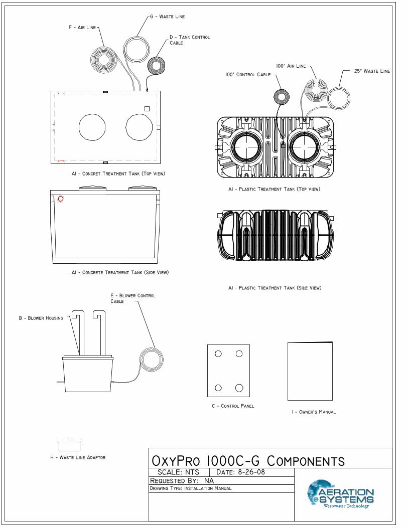
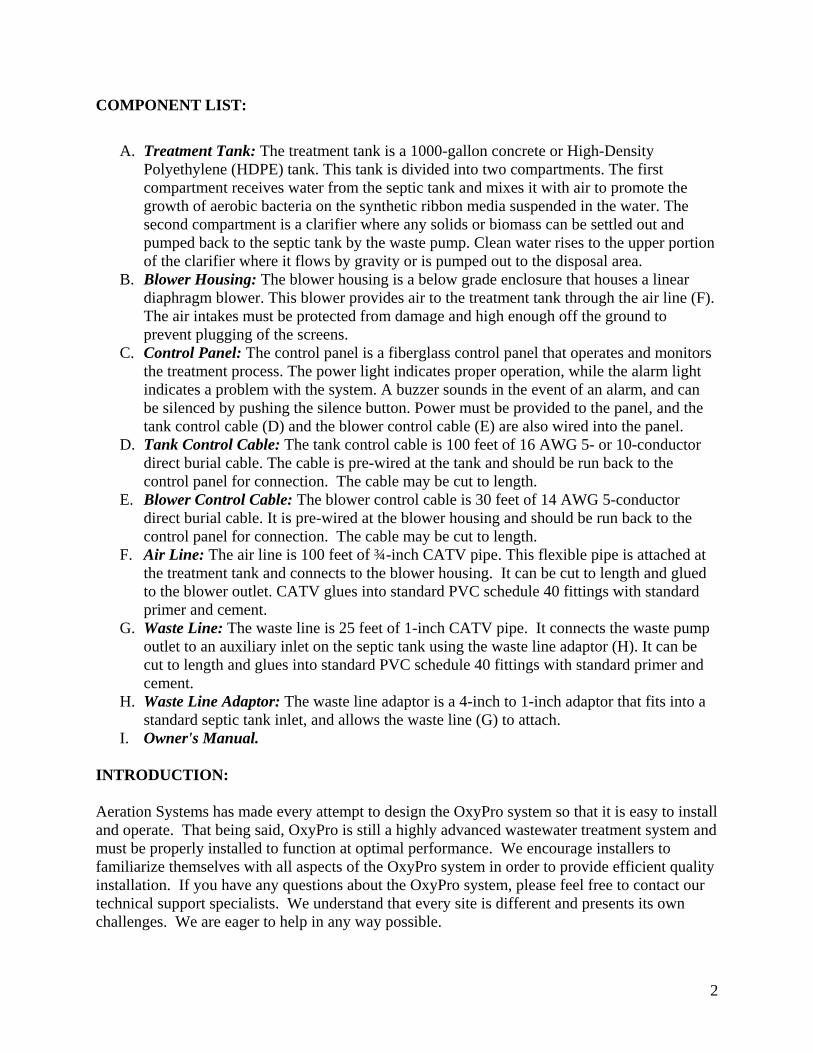
COMPONENT LIST:
A. Treatment Tank: The treatment tank is a 1000-gallon concrete or High-Density
Polyethylene (HDPE) tank. This tank is divided into two compartments. The first compartment receives water from the septic tank and mixes it with air to promote the growth of aerobic bacteria on the synthetic ribbon media suspended in the water. The second compartment is a clarifier where any solids or biomass can be settled out and pumped back to the septic tank by the waste pump. Clean water rises to the upper portion of the clarifier where it flows by gravity or is pumped out to the disposal area.
B. Blower Housing: The blower housing is a below grade enclosure that houses a linear diaphragm blower. This blower provides air to the treatment tank through the air line (F). The air intakes must be protected from damage and high enough off the ground to prevent plugging of the screens.
C. Control Panel: The control panel is a fiberglass control panel that operates and monitors the treatment process. The power light indicates proper operation, while the alarm light indicates a problem with the system. A buzzer sounds in the event of an alarm, and can be silenced by pushing the silence button. Power must be provided to the panel, and the tank control cable (D) and the blower control cable (E) are also wired into the panel.
D. Tank Control Cable: The tank control cable is 100 feet of 16 AWG 5- or 10-conductor direct burial cable. The cable is pre-wired at the tank and should be run back to the control panel for connection. The cable may be cut to length.
E. Blower Control Cable: The blower control cable is 30 feet of 14 AWG 5-conductor direct burial cable. It is pre-wired at the blower housing and should be run back to the control panel for connection. The cable may be cut to length.
F. Air Line: The air line is 100 feet of ¾-inch CATV pipe. This flexible pipe is attached at the treatment tank and connects to the blower housing. It can be cut to length and glued to the blower outlet. CATV glues into standard PVC schedule 40 fittings with standard primer and cement.
G. Waste Line: The waste line is 25 feet of 1-inch CATV pipe. It connects the waste pump outlet to an auxiliary inlet on the septic tank using the waste line adaptor (H). It can be cut to length and glues into standard PVC schedule 40 fittings with standard primer and cement.
H. Waste Line Adaptor: The waste line adaptor is a 4-inch to 1-inch adaptor that fits into a standard septic tank inlet, and allows the waste line (G) to attach.
I. Owner's Manual. INTRODUCTION: Aeration Systems has made every attempt to design the OxyPro system so that it is easy to install and operate. That being said, OxyPro is still a highly advanced wastewater treatment system and must be properly installed to function at optimal performance. We encourage installers to familiarize themselves with all aspects of the OxyPro system in order to provide efficient quality installation. If you have any questions about the OxyPro system, please feel free to contact our technical support specialists. We understand that every site is different and presents its own challenges. We are eager to help in any way possible.

3
PROCESS DESCRIPTION: Wastewater from the house flows into a septic tank, where settling and anaerobic digestion occur with the formation of sludge and scum. This material is removed periodically by a pump truck. Clarified wastewater flows from the septic tank into the OxyPro tank. The first (inlet) compartment of the OxyPro tank is the aeration compartment. Air is pumped under pressure from an efficient, linear-diaphragm pump through flexible-membrane bubble diffusers anchored to the bottom of the tank. This creates a number of curtains of tiny air bubbles, which allow for excellent oxygen transfer efficiency. Through this process of aeration, an aerobic environment is established in which oxygen-loving microorganisms can flourish and digest the organic material in the wastewater. These microorganisms form large, visible colonies on a synthetic ribbon media suspended in the water column. Eventually, these colonies become too large and heavy, and due to the agitation caused by the air bubbles, slough off. The sloughed colonies are carried by the wastewater into the next compartment.
The second compartment is designed as an up-flow clarifier. This means that the wastewater is given a calm environment where it flows slowly upward to the outlet. The quiescent environment allows the sloughed colonies and other suspended particles to settle to the bottom of the clarifier. A submersible pump periodically pumps the accumulated sludge from the bottom of the clarifier to the septic tank, where it is ultimately removed when the septic tank is serviced. The cleaned and clarified effluent from the OxyPro flows or is pumped out of the clarifier to a subsurface disposal area.
OFFLOADING/UNPACKING INSTRUCTIONS: In the case of a concrete tank, the OxyPro will be delivered on a boom truck. Access must be provided for the boom truck to approach the excavation close enough to set the tank. Care must be taken with cables or slings to prevent damage to air and waste lines as well as the control cable and outlet. Any one present should stand clear of the tank and truck while the tank is being placed into the hole. If the OxyPro is in an HDPE tank, it may be delivered on a flatbed truck or trailer. In this case, it will be place into the excavation by the excavator, using slings and a backhoe. Again, care must be taken with any lines attached to the tank, and any one present should stand clear of the tank and the equipment. The control enclosure and the blower enclosure will be delivered at the same time. The waste line adaptor, and the owner's manual will be packaged with the control enclosure, as well as an electrical schematic and wiring diagram. If the delivery occurs before there is a place to install these components, they should be stored out of the elements and protected from damage until they can be installed. INSTALLATION REQUIREMENTS: The installation of an OxyPro is relatively simple, but should be performed by qualified personnel only. Improper installation of the system may cause damage to the OxyPro or the disposal area, or may cause sewage back-up.

4
The electrical connections should be made by a licensed electrician to prevent damage to the system and possible injury. All plumbing connections should be made by qualified personnel. Each connection should be watertight. All PVC-to-PVC connections should be made with primer and solvent cement. All sewer connections with rubber boots should use appropriate stainless steel boot clamps. INSTALLATION SEQUENCE: The hole for the OxyPro Processor tank should be dug so that all of the base is on natural ground. If any of the base is on old fill or planned fill because of a steep slope, the base must be prepared and compacted to make sure the bearing capacity of the base is equal throughout. If the base is on previously filled ground, precautions must be taken to remove any organics such as peat or wood before compacting the base. Over-dig the hole for the OxyPro Processor tank 18- to 24-inches on the sides, and 6- to 12-inches on the bottom. Fill the bottom of the hole with a well-compacted sand and gravel mixture up to the base elevation for the tank. The tank must be installed level to insure proper operation. If a water table higher than the base of the hole is indicated, the tank must be anchored to account for hydrostatic pressure and possible displacement of the tank. Both the septic and the OxyPro Processor tanks must be watertight. Use watertight fittings at the inlet and outlet points of all pipes and cables. All riser connections into the septic and OxyPro Processor tanks must be sealed watertight. The riser covers must be installed above the elevation of the highest seasonal water table. Install any risers and covers before beginning to backfill. It is important to keep foreign debris out of the processor tank. Compact the backfill under the inlet and outlet pipes, as well as under the electrical, air and waste lines. It is preferable for the covers to be at the surface with no overlying fill. The covers must be within 6-inches of finished grade. If notified in advance, Aeration Systems can provide risers, at additional cost. Plumb the outlet of the septic tank into the inlet on the OxyPro. Plumb the outlet of the OxyPro (4-inch DWV, or 2-inch sched. 40) to the drain field. Run the provided 1-inch waste line from the treatment tank into a side inlet on the septic tank, using the provided adapter. The CATV pipe can be glued using normal PVC primer and cement. Hang the control panel inside a storage area in the building. A basement, crawl space, or garage will work fine, as long as ready access is available for maintenance and repair. Trench the provided control cable from processor tank to the control panel, and make the required electrical connections. The control cable is rated for direct burial but conduit may be required by code and is strongly recommended.

5
Run the provided ¾-inch airline from the processor tank to the blower enclosure. The blower enclosure is typically located underground just outside of the foundation wall where the control cable enters to the inside. Run the provided blower control cable to the control panel and make the necessary electrical connection. Install the provided air vent intake pipe next to the foundation wall, if possible, with a minimum 12-inch separation from the ground to the intake of the pipe. Bring power from the circuit breaker panel in the house. System power requirements vary by model and are listed in the electrical instructions included in the panel. All breakers should be dedicated to the treatment system, and not have additional appliances, lights, or outlets on the circuit. The location of all buried covers must be noted on a sketch plan, with measurements to fixed features, such as house corners. This sketch should be stored in the OxyPro control enclosure. START UP PROCEDURE: Once installed, the OxyPro system can be turned on. To turn the system on, make sure that the mode switch on the PLC is in the run position, and that the supplemental protectors are in the on position. Turn the circuit breaker on. The PLC should power up and the power light on the front of the control panel will light up. The control panel will not run the blower or any pumps until there is enough water in the OxyPro tank to trigger the low water float. If there is not enough water in the tank, it is recommended that the low water float be triggered by hand to ensure that the blower turns on, and air comes out of the diffusers. The system may be left on to activate as soon as enough water has entered the OxyPro from the septic tank. Check to confirm that the air intakes on the blower vault are clear of obstructions and that the ventilation fan is circulating air.
There is no need to pre-fill the OxyPro unless hydraulic displacement is a concern. No special additive or chemicals are needed to start the treatment process.
REPAIR OR REPLACEMENT INSTRUCTIONS: Before working on any component of the OxyPro system, make sure that the power to the unit has been turned off. Replacement components are available from: Aeration Systems, LLC 155 Gray Road Falmouth, ME 04105 Phone Number: (207) 797-7351 Email Address: [email protected] Blower - If the blower is not operational, confirm that the problem does not lie in the control panel. If the blower does need to be replaced, turn the system off, expose the top of the blower enclosure and remove the cover. Disconnect the blower from the rubber hose connection to the enclosure outlet. Cut the electrical connections to the blower and remove the old blower. Replace

6
the blower with a new or rebuilt blower. Connect the new blower to the enclosure outlet, and make the new electrical connections with heat shrink butt connectors. Use a heat gun to seal the connectors against water intrusion. Confirm proper operation of the new blower. Place the enclosure cover back into place, and cover with the dirt removed earlier. Ensure that the air intakes are clear of debris. Waste Pump - If the waste pump is not operational, turn power to the system off. Open the outlet cover of the OxyPro. Cut the discharge pipe for the waste pump and pull the waste pump out for inspection. Remove the impeller cover plate from the pump by removing the screws that hold it in place. Look for obstructions in the impeller and in the discharge line. If an obstruction is found remove it, reassemble the pump and confirm proper operation. If no obstruction is found, test the pump to see if it is operational. If not, the pump will have to be replaced. Remove the intake and outlet pipes from the old waste pump. Take care to prevent them from falling back into the tank. Expose the cover of the junction box on the top of the OxyPro tank and cut the connections for the waste pump. Remove the old pump and cord. Feed the wire for the new waste pump through the cord grip in the bottom of the junction box and make the electrical connections using heat-shrink butt connectors. Attach the inlet and outlet piping to the new waste pump and ensure proper operation of the new pump. Make sure that all the air is removed from the inlet piping to prevent the pump from getting air bound. If the waste pump will not draw water through the inlet piping, make sure the pump is not air bound. If the intake piping is clogged, connect the inlet pipe to the pump discharge and run the pump to force water backwards through the inlet. This will help to dislodge any obstruction. Discharge Pump - If the discharge pump is not operational confirm that the force main to the disposal area is not obstructed. If the pump does not operate, expose the junction box on top of the OxyPro tank and disconnect the discharge pump. Open the outlet cover of the tank and remove the pump by releasing the quick disconnect on the outlet. Pull the pump out of the tank and remove the discharge elbow and the base plate with the pump leg. Attach the discharge elbow and the base plate to the new pump and place back into position, ensuring solid connection of the quick disconnect. Feed the wire through the cord grip and make the electrical connections with heat shrink butt connectors. Check to confirm proper operation of the pump. PLC - If the PLC is not operational, turn the power off. Remove the wiring harness by removing the two screws (one on each end) from the PLC. Pull the Din rail clamp on the PLC down to release the PLC from the Din rail. Replace the old PLC with a new one and snap onto the din rail, ensuring positive attachment to the Din rail. Connect the wiring harness to the new PLC and restore power to the system. Place the toggle switch on the PLC in Terminal mode and upload the appropriate program. Place the PLC in Run mode and confirm proper operation of all components.


OxyPro 1000C-Gravity Electrical Hookup
A 15 amp 120VAC branch circuit is required to provide power to the OxyPro system.
Each OxyPro treatment tank will be delivered with 100 feet of 7 conductor 14 AWG tray cable attached. Cable
diameter is 0.5 inches. Below is the wire color coding, its function, and its terminal designation at the controller.
Treatment tank cable - 7/16 tray cable:
Yellow Ground TB-3
Blue Float Switch L1 TB-4
Orange Low Level Float TB-5
Brown High Level Float TB-7
Black Waste Pump L1 TB-8
Red Waste Pump Neutral TB-9
Red/Black Unused
This model of OxyPro is equipped with a separate blower enclosure. The blower enclosure is delivered with 25 feet
of 5 conductor 14 AWG tray cable. Below is the wire color coding, its function, and its terminal designation at the
controller.
Black Blower L1 TB-13
Red Blower Neutral TB-14
Yellow Blower Ground TB-15
Blue Air Switch L1 TB-16
Orange Air Switch Neutral TB-17
The controller will have a label on its interior describing the function of each terminal. These are repeated below:
TB-1 120 VAC Power from 15A breaker at house panel
TB-2 Neutral from house panel
TB-3 Ground
TB-4 Float Switch L1
TB-5 Low Level Float
TB-6 Unused in this model
TB-7 High Water Float
TB-8 Waste Pump L1
TB-9 Waste Pump Neutral
TB-10 Unused in this model
TB-11 Unused in this model
TB-12 Unused in this model
TB-13 Blower L1
TB-14 Blower Neutral
TB-15 Blower Ground
TB-16 Air Switch L1
TB-17 Air Switch Neutral


OxyPro 1000C-Pumped Electrical Hookup
A 20 amp 120VAC branch circuit is required to provide power to the OxyPro system.
Each OxyPro treatment tank will be delivered with 100 feet of 10 conductor 14 AWG tray cable attached. Cable
diameter is 0.5 inches. Below is the wire color coding, its function, and its terminal designation at the controller.
Treatment tank cable - 10/14 tray cable:
Yellow Ground TB−3
Blue/Black Float Switch Feed TB−4
Orange/Black Low Level Float TB−5
Blue Dose Pump On TB−6
Orange High Level Float TB−7
Black Waste Pump Hot TB−8
Red Waste Pump Neutral TB−9
Yellow/Black Dose Pump Hot TB−10
Red/Black Dose Pump Neutral TB−11
Brown Unused
This model of OxyPro is equipped with a separate blower enclosure. The blower enclosure is delivered with 25 feet
of 5 conductor 14 AWG tray cable. Below is the wire color coding, its function, and its terminal designation at the
controller.
Black Blower L1 TB-13
Red Blower Neutral TB-14
Yellow Blower Ground TB-15
Blue Air Switch l1 TB-16
Orange Air Switch Neutral TB-17
The controller will have a label on its interior describing the function of each terminal. These are repeated below:
TB-1 120 VAC Power from 15A breaker at house panel
TB-2 Neutral from house panel
TB-3 Ground
TB-4 Float Switch L1
TB-5 Low Level Float
TB-6 Dose Pump Control
TB-7 High Water Float
TB-8 Waste Pump L1
TB-9 Waste Pump Neutral
TB-10 Dose Pump L1
TB-11 Dose Pump Neutral
TB-12 Unused in this model
TB-13 Blower L1
TB-14 Blower Neutral
TB-15 Blower Ground
TB-16 Air Switch L1
TB-17 Air Switch Neutral

