installation manual - 485 data module
TRANSCRIPT

485i-Module-IA-en-19 | Version 1.9 ENGLISH
Communication Interface for SMA Inverters485 Data ModuleInstallation Manual

Legal Provisions SMA Solar Technology AG
2 485i-Module-IA-en-19 Installation Manual
Legal ProvisionsThe information contained in these documents is the property of SMA Solar Technology AG. Any publication, whether in whole or in part, requires prior written approval by SMA Solar Technology AG. Internal reproduction used solely for the purpose of product evaluation or other proper use is allowed and does not require prior approval.
SMA WarrantyYou can download the current warranty conditions from the Internet at www.SMA-Solar.com.
TrademarksAll trademarks are recognized, even if not explicitly identified as such. Missing designations do not mean that a product or brand is not a registered trademark. The BLUETOOTH® word mark and logos are registered trademarks owned by Bluetooth SIG, Inc. and any use of these marks by SMA Solar Technology AG is under license. Modbus® is a registered trademark of Schneider Electric and is licensed by the Modbus Organization, Inc.QR Code is a registered trademark of DENSO WAVE INCORPORATED.Phillips® and Pozidriv® are registered trademarks of Phillips Screw Company.Torx® is a registered trademark of Acument Global Technologies, Inc.
SMA Solar Technology AGSonnenallee 134266 NiestetalGermanyTel. +49 561 9522-0Fax +49 561 9522-100www.SMA.deE-mail: [email protected]© 2004 until 2016 SMA Solar Technology AG. All rights reserved.

SMA Solar Technology AG Table of Contents
Installation Manual 485i-Module-IA-en-19 3
Table of Contents1 Information on this Document. . . . . . . . . . . . . . . . . . . . . . . . . . . 42 Safety . . . . . . . . . . . . . . . . . . . . . . . . . . . . . . . . . . . . . . . . . . . . . . 6
2.1 Intended Use . . . . . . . . . . . . . . . . . . . . . . . . . . . . . . . . . . . . . . . . . . . . 62.2 Skills of Qualified Persons . . . . . . . . . . . . . . . . . . . . . . . . . . . . . . . . . . 72.3 Safety Information . . . . . . . . . . . . . . . . . . . . . . . . . . . . . . . . . . . . . . . . 7
3 Scope of Delivery . . . . . . . . . . . . . . . . . . . . . . . . . . . . . . . . . . . . . 83.1 Order Option 485 Data Module Pre-Installed in the Inverter . . . . . . . 83.2 Order Option 485 Data Module as Retrofit Kit . . . . . . . . . . . . . . . . . 8
4 Product Description . . . . . . . . . . . . . . . . . . . . . . . . . . . . . . . . . . . 94.1 485 Data Module . . . . . . . . . . . . . . . . . . . . . . . . . . . . . . . . . . . . . . . . 94.2 Type Label . . . . . . . . . . . . . . . . . . . . . . . . . . . . . . . . . . . . . . . . . . . . . . 94.3 Cable Gland . . . . . . . . . . . . . . . . . . . . . . . . . . . . . . . . . . . . . . . . . . . 10
5 Connection . . . . . . . . . . . . . . . . . . . . . . . . . . . . . . . . . . . . . . . . . 115.1 Device Overview . . . . . . . . . . . . . . . . . . . . . . . . . . . . . . . . . . . . . . . . 115.2 Installing the 485 Data Module in the Inverter . . . . . . . . . . . . . . . . . 125.3 Connecting the 485 Data Module . . . . . . . . . . . . . . . . . . . . . . . . . . 14
6 Decommissioning . . . . . . . . . . . . . . . . . . . . . . . . . . . . . . . . . . . . 186.1 Disassembling the 485 Data Module . . . . . . . . . . . . . . . . . . . . . . . . 186.2 Packaging the 485 Data Module for Shipping . . . . . . . . . . . . . . . . . 196.3 Disposing of the 485 Data Module . . . . . . . . . . . . . . . . . . . . . . . . . 19
7 Troubleshooting . . . . . . . . . . . . . . . . . . . . . . . . . . . . . . . . . . . . . 208 Technical Data . . . . . . . . . . . . . . . . . . . . . . . . . . . . . . . . . . . . . . 219 Contact . . . . . . . . . . . . . . . . . . . . . . . . . . . . . . . . . . . . . . . . . . . . 22

1 Information on this Document SMA Solar Technology AG
4 485i-Module-IA-en-19 Installation Manual
1 Information on this DocumentValidityThis document is valid for device type "485I-MOD-G1 BGCB" with hardware version B5 and firmware version 4.00 or higher.
Target GroupThis document is intended for qualified persons. Only persons with the appropriate skills are allowed to perform the activities described in this document (see Section 2.2 "Skills of Qualified Persons", page 7).
SymbolsSymbol Explanation
Indicates a hazardous situation which, if not avoided, will result in death or serious injuryIndicates a hazardous situation which, if not avoided, can result in death or serious injuryIndicates a hazardous situation which, if not avoided, can result in minor or moderate injuryIndicates a situation which, if not avoided, can result in property damage
Information that is important for a specific topic or goal, but is not safety-relevant
☐ Indicates a requirement for meeting a specific goal☑ Desired result✖ A problem that might occur

SMA Solar Technology AG 1 Information on this Document
Installation Manual 485i-Module-IA-en-19 5
Typographies
Nomenclature
Abbreviations
FiguresThe figures in this document can vary slightly for inverters of types STP 1x000TL-10, STP xx000TLHE-10, STP xx000TLEE-10, STP xx000TL-30, SB x000TL-21 and WB xx00TL-21.
Typography Explanation Examplebold • Display texts
• Elements on a user interface• Terminals• Elements to be selected• Elements to be entered
• The value can be found in the field Energy.
• Select Settings.• Enter the value 10 in the field
Minutes.
> • Connects several elements to be selected
• Select Settings > Date.
[Button/Key] • Button or key to be selected or pressed
• Select [Next].
Complete designation Designation in this documentElectronic Solar Switch ESSPV System SystemSMA Inverter Inverter
Abbreviation Designation ExplanationAC Alternating Current Alternating currentDC Direct Current Direct current
2 Safety SMA Solar Technology AG
6 485i-Module-IA-en-19 Installation Manual
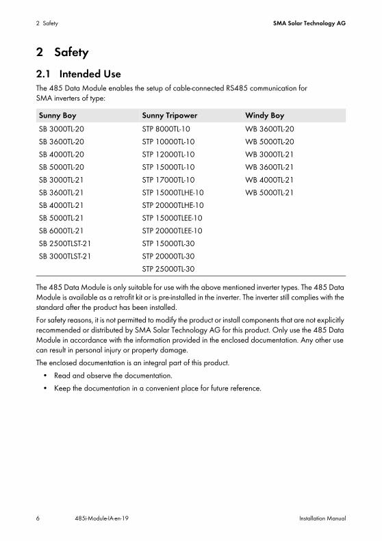
2 Safety2.1 Intended UseThe 485 Data Module enables the setup of cable-connected RS485 communication for SMA inverters of type:
The 485 Data Module is only suitable for use with the above mentioned inverter types. The 485 Data Module is available as a retrofit kit or is pre-installed in the inverter. The inverter still complies with the standard after the product has been installed.For safety reasons, it is not permitted to modify the product or install components that are not explicitly recommended or distributed by SMA Solar Technology AG for this product. Only use the 485 Data Module in accordance with the information provided in the enclosed documentation. Any other use can result in personal injury or property damage.The enclosed documentation is an integral part of this product.
• Read and observe the documentation.• Keep the documentation in a convenient place for future reference.
Sunny Boy Sunny Tripower Windy BoySB 3000TL-20SB 3600TL-20SB 4000TL-20SB 5000TL-20SB 3000TL-21SB 3600TL-21SB 4000TL-21SB 5000TL-21SB 6000TL-21SB 2500TLST-21SB 3000TLST-21
STP 8000TL-10STP 10000TL-10STP 12000TL-10STP 15000TL-10STP 17000TL-10STP 15000TLHE-10STP 20000TLHE-10STP 15000TLEE-10STP 20000TLEE-10STP 15000TL-30STP 20000TL-30STP 25000TL-30
WB 3600TL-20WB 5000TL-20WB 3000TL-21WB 3600TL-21WB 4000TL-21WB 5000TL-21

SMA Solar Technology AG 2 Safety
Installation Manual 485i-Module-IA-en-19 7
2.2 Skills of Qualified PersonsThe activities described in this document must only be performed by qualified persons. Qualified persons must have the following skills:
• Training in the installation and commissioning of electrical devices and installations• Knowledge of how to deal with the dangers and risks associated with installing and using
electrical devices and installations• Knowledge of all applicable standards and directives• Knowledge of how an inverter works and is operated• Knowledge of and compliance with this document and all safety information
2.3 Safety Information Electric ShockLethal voltages are present in the conductive parts of the inverter.
• Prior to performing any work on the inverter, disconnect the inverter from all voltage sources on the AC and DC sides (see inverter installation manual).
Burn HazardsSome parts of the inverter enclosure can get hot during operation.
• During operation, do not touch any parts other than the enclosure lid of the inverter.
Electrostatic DischargeBy touching electronic components, you can damage or even destroy the inverter through electrostatic discharge (ESD).
• Ground yourself before touching any inverter component.
Interference in Data Transmission due to AC CablesDuring operation, AC cables generate an electromagnetic field which may induce interference in plant communication.
• Lay the RS485 communication cables using suitable fastening material and with a minimum clearance of 50 mm to the AC cables.
3 Scope of Delivery SMA Solar Technology AG
8 485i-Module-IA-en-19 Installation Manual
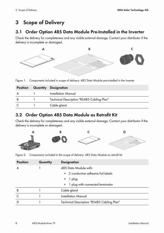
3 Scope of Delivery3.1 Order Option 485 Data Module Pre-Installed in the InverterCheck the delivery for completeness and any visible external damage. Contact your distributor if the delivery is incomplete or damaged.
Figure 1: Components included in scope of delivery: 485 Data Module pre-installed in the inverter
3.2 Order Option 485 Data Module as Retrofit KitCheck the delivery for completeness and any visible external damage. Contact your distributor if the delivery is incomplete or damaged.
Figure 2: Components included in the scope of delivery: 485 Data Module as retrofit kit
Position Quantity DesignationA 1 Installation ManualB 1 Technical Description "RS485 Cabling Plan"C 1 Cable gland
Position Quantity DesignationA 1 485 Data Module with:
• 2 conductive adhesive foil labels• 1 plug• 1 plug with connected terminator
B 1 Cable glandC 1 Installation ManualD 1 Technical Description "RS485 Cabling Plan"

SMA Solar Technology AG 4 Product Description
Installation Manual 485i-Module-IA-en-19 9
4 Product Description4.1 485 Data ModuleThe 485 Data Module enables the setup of wired RS485 communication for SMA inverters.
Figure 3: Design of the 485 Data Module
4.2 Type LabelThe type label clearly identifies the 485 Data Module. The type label is located at the bottom right on the back of the 485 Data Module.
Figure 4: Information on the type label
Position DesignationA Hexagon socket screwB Plug-in connectorC Plug with connected resistorD Ribbon cable plugE Ribbon CableF Type label

4 Product Description SMA Solar Technology AG
10 485i-Module-IA-en-19 Installation Manual
You will require the information on the type label to use the 485 Data Module safely and when seeking customer support from the SMA Service Line. The type label must remain permanently attached to the 485 Data Module.
Symbol on the Type Label
4.3 Cable GlandThe cable gland provides a sturdy, tightly sealed connection of the cables to the inverter enclosure. The cable gland also protects the inverter from dust and moisture intrusion.
Figure 5: Product description: Cable gland
Position Designation ExplanationA Serial No. Serial number of the 485 Data ModuleB Version Hardware version of the 485 Data ModuleC Type Device type
Symbol Designation ExplanationCE marking The 485 Data Module complies with the
requirements of the applicable EC directives.
Position DesignationA Filler plugB SealC Swivel nutD Counter nut

SMA Solar Technology AG 5 Connection
Installation Manual 485i-Module-IA-en-19 11
5 Connection5.1 Device Overview
Figure 6: Overview of the connection area
Position DesignationA Flipped up display with screwB Cable route to the plugs of the 485 Data ModuleC Inverter enclosure opening for cable glandD Mounting position of the 485 Data Module in the inverter

5 Connection SMA Solar Technology AG
12 485i-Module-IA-en-19 Installation Manual
5.2 Installing the 485 Data Module in the Inverter
2. Release the screw of the display far enough to allow the display to be flipped up.
3. Flip the display up until it snaps into place.4. Push the pre-mounted filler plug out of the second
hole from the left in the inverter enclosure.
5. Attach the cable gland to the enclosure opening using the counter nut.
1.Danger to life due to electric shock when opening the inverter Death or serious injuries
• Disconnect the inverter from all voltage sources on the AC and DC sides and open it (see the inverter installation manual).

SMA Solar Technology AG 5 Connection
Installation Manual 485i-Module-IA-en-19 13
6. Insert the 485 Data Module and push the ribbon cable upwards behind the display. The key on the top edge of the 485 Data Module must fit into the hole in the plastic retainer in the inverter.
7. 485 Data Module hand-tight using a hexagon socket screw (AF 3, torque: 1.5 Nm).
8. Flip the display down.9. Plug the ribbon cable plug onto the center
connector strip.

5 Connection SMA Solar Technology AG
14 485i-Module-IA-en-19 Installation Manual
5.3 Connecting the 485 Data ModuleTo achieve a good signal quality, observe the cable recommendation (see Technical Description "RS485 Cabling Plan").
Procedure:To connect the 485 Data Module, perform the following work steps in the prescribed sequence. The exact procedure is described in the following sections.
• Prepare the cable• Connect the cable to the 485 Data Module
Preparing the Cable1. Remove 40 mm of the cable sheath at the end of the cable which is to be connected to the
485 Data Module.2. Shorten the cable shield to 15 mm.3. Fold the surplus cable shield back over the cable
sheath.
4. Wrap the cable shield in conductive adhesive foil.
5. Strip off the insulation of the three insulated conductors by 6 mm. The two insulated conductors used for communication must be a twisted pair.
6. Shorten all other conductors flush with the cable sheath.
Interference in data transmission due to AC cablesDuring operation, AC cables generate an electromagnetic field which may induce interference in plant communication.
• Lay the RS485 communication cables using suitable fastening material and with a minimum clearance of 50 mm to the AC cables.

SMA Solar Technology AG 5 Connection
Installation Manual 485i-Module-IA-en-19 15
Connecting the Cable to the 485 Data Module1. Flip the display up until it snaps into place.2. Unscrew the swivel nut of the cable gland on the
inverter.
3. Press the seal out of the cable gland from the inside.
4. Route the cable from the outside into the inverter through the unfastened swivel nut and the cable gland.
5. Remove one of the filler-plugs from the seal for each cable.
6. Insert the cable into the seal.
7. Press the seal into the cable gland. Ensure that any unused cable openings are sealed with filler plugs.
8. Screw the swivel nut of the cable gland on loosely.

5 Connection SMA Solar Technology AG
16 485i-Module-IA-en-19 Installation Manual
9. Remove or connect the terminator:• If two cables are connected, open the spring clamp terminals of the plug with the connected
terminator and remove the terminator.• If one cable is connected, the terminator in the unused plug must be connected in terminals
2 and 7.10. Open the spring clamp terminals on the plug.11. Connect the insulated conductors to the plug terminals and note down the color of the insulated
conductors. The allocation of cables to plugs can be done in any order.
12. Close the spring clamp terminals.13. Push the cable with the cable shield into the shield connection terminal on the 485 Data
Module.☑ Two cables are connected to the 485 data
module.
Signal 485 Data Module RS485 bus Insulated conductor color
GND 5 5Data+ 2 2Data- 7 7

SMA Solar Technology AG 5 Connection
Installation Manual 485i-Module-IA-en-19 17
or☑ One cable is connected to the 485 data
module.
14. Fasten the swivel nut on the cable gland hand-tight. This relieves pull strains on the cables.15. Flip the display down and fasten the screw of the display hand-tight.16. Close the inverter (see inverter installation manual).17. Connect the other cable end to the RS485 bus (for information on the terminal assignment and
wiring in the system, see the technical description "RS485 Cabling Plan").

6 Decommissioning SMA Solar Technology AG
18 485i-Module-IA-en-19 Installation Manual
6 Decommissioning6.1 Disassembling the 485 Data Module
2. Press the left-hand and right-hand lock hooks outwards and remove the ribbon cable plug from the center connector strip of the inverter.
3. Release the screw of the display far enough to allow the display to be flipped up.4. Flip the display up until it snaps into place.5. Unscrew the swivel nut from the cable gland.6. Open the spring clamp terminals of the plug on the 485 Data Module.7. Remove the cables from the 485 Data Module.8. Unscrew the counter nut of the cable gland.9. Pull the cable gland and cables out of the inverter.
10. Release the screw of the 485 Data Module and remove the 485 Data Module.11. Close the spring clamp terminals of the plugs on the 485 Data Module.12. Flip the display down and fasten the display screw hand-tight.13. Seal the opening in the inverter enclosure with the filler plug for enclosure openings.14. Close the inverter (see inverter installation manual).
1.Danger to life due to electric shock when opening the inverterDeath or serious injuries
• Disconnect the inverter from all voltage sources on the AC and DC sides and open it (see the inverter installation manual).
2
1
1

SMA Solar Technology AG 6 Decommissioning
Installation Manual 485i-Module-IA-en-19 19
6.2 Packaging the 485 Data Module for Shipping• Pack the 485 Data Module. To do so, use the original packaging or packaging that is suitable
for the weight and size of the 485 Data Module.
6.3 Disposing of the 485 Data Module• Dispose of the 485 Data Module in accordance with the regulations for the disposal of
electronic waste applicable at the installation site.orReturn the 485 Data Module to SMA Solar Technology AG at your own expense labeled "ZUR ENTSORGUNG" ("FOR DISPOSAL") (see Section 9 "Contact", page 22).
7 Troubleshooting SMA Solar Technology AG
20 485i-Module-IA-en-19 Installation Manual
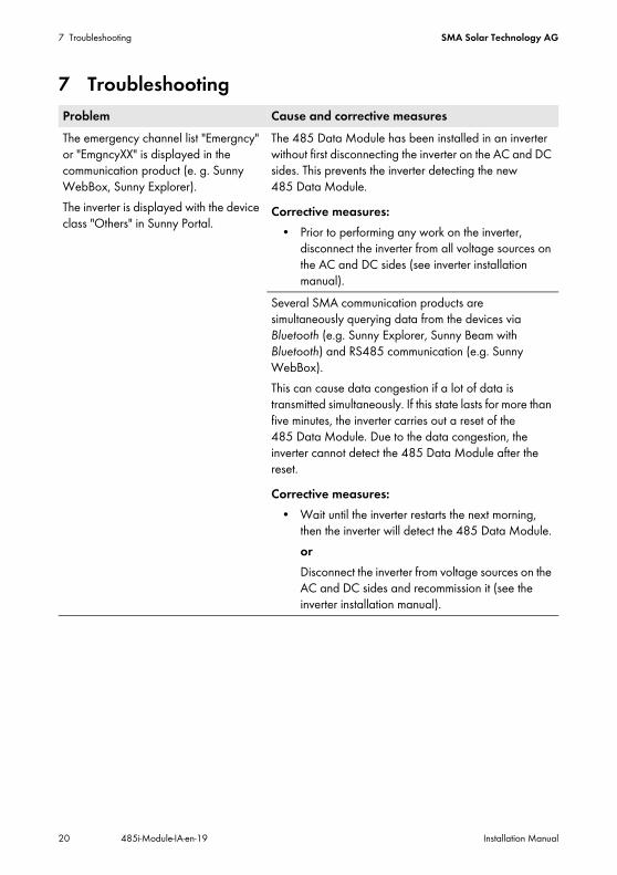
7 TroubleshootingProblem Cause and corrective measuresThe emergency channel list "Emergncy" or "EmgncyXX" is displayed in the communication product (e. g. Sunny WebBox, Sunny Explorer).The inverter is displayed with the device class "Others" in Sunny Portal.
The 485 Data Module has been installed in an inverter without first disconnecting the inverter on the AC and DC sides. This prevents the inverter detecting the new 485 Data Module.Corrective measures:
• Prior to performing any work on the inverter, disconnect the inverter from all voltage sources on the AC and DC sides (see inverter installation manual).
Several SMA communication products are simultaneously querying data from the devices via Bluetooth (e.g. Sunny Explorer, Sunny Beam with Bluetooth) and RS485 communication (e.g. Sunny WebBox).This can cause data congestion if a lot of data is transmitted simultaneously. If this state lasts for more than five minutes, the inverter carries out a reset of the 485 Data Module. Due to the data congestion, the inverter cannot detect the 485 Data Module after the reset.Corrective measures:
• Wait until the inverter restarts the next morning, then the inverter will detect the 485 Data Module.orDisconnect the inverter from voltage sources on the AC and DC sides and recommission it (see the inverter installation manual).

SMA Solar Technology AG 8 Technical Data
Installation Manual 485i-Module-IA-en-19 21
8 Technical DataMechanical Data
Communication
Terminals
Ambient Conditions during Operation
Ambient Conditions for Storage/Transport
Width x height x depth 73 mm x 88 mm x 34 mmWeight 71 g
Communication interface RS485Maximum cable length 1200 m
Type of plug 4-pole spring-cage terminalNumber of RS485 connections 2
Ambient temperature − 25°C to +85°CRelative humidity, non-condensing 5% to 95%Maximum height above mean sea level 3000 m
Ambient temperature − 40°C to +85°CRelative humidity, non-condensing 5% to 95 %Maximum height above mean sea level 3000 m
9 Contact SMA Solar Technology AG
22 485i-Module-IA-en-19 Installation Manual
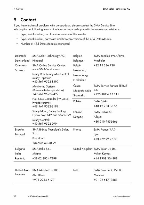
9 ContactIf you have technical problems with our products, please contact the SMA Service Line. We require the following information in order to provide you with the necessary assistance:
• Type, serial number, and firmware version of the inverter• Type, serial number, hardware and firmware version of the 485 Data Module• Number of 485 Data Modules connected
DanmarkDeutschlandÖsterreichSchweiz
SMA Solar Technology AGNiestetalSMA Online Service Center: www.SMA-Service.comSunny Boy, Sunny Mini Central, Sunny Tripower: +49 561 9522-1499Monitoring Systems (Kommunikationsprodukte): +49 561 9522-2499Fuel Save Controller (PV-Diesel Hybridsysteme): +49 561 9522-3199Sunny Island, Sunny Backup, Hydro Boy: +49 561 9522-399Sunny Central: +49 561 9522-299
BelgienBelgiqueBelgiëLuxemburgLuxembourgNederland
SMA Benelux BVBA/SPRLMechelen+32 15 286 730
ČeskoMagyarországSlovensko
SMA Service Partner TERMS a.s.+420 387 6 85 111
Polska SMA Polska+48 12 283 06 66
ΕλλάδαΚύπρος
SMA Hellas AEΑθήνα+30 210 9856666
EspañaPortugal
SMA Ibérica Tecnología Solar, S.L.U.Barcelona+34 935 63 50 99
France SMA France S.A.S.Lyon+33 472 22 97 00
BulgariaItaliaRomânia
SMA Italia S.r.l.Milano+39 02 8934-7299
United Kingdom SMA Solar UK Ltd.Milton Keynes+44 1908 304899
United Arab Emirates
SMA Middle East LLCAbu Dhabi+971 2234 6177
India SMA Solar India Pvt. Ltd.Mumbai+91 22 61713888

SMA Solar Technology AG 9 Contact
Installation Manual 485i-Module-IA-en-19 23
대한민국 SMA Technology Korea Co., Ltd.서울+82-2-520-2666
SMA Solar (Thailand) Co., Ltd.
+66 2 670 6999South Africa SMA Solar Technology
South Africa Pty Ltd.Cape Town08600SUNNY (08600 78669)International: +27 (0)21 826 0600
ArgentinaBrasilChilePerú
SMA South America SPASantiago+562 2820 2101
Australia SMA Australia Pty Ltd.SydneyToll free for Australia: 1800 SMA AUS (1800 762 287)International: +61 2 9491 4200
Other countries International SMA Service LineNiestetal 00800 SMA SERVICE (+800 762 7378423)

www.SMA-Solar.comSMA Solar Technology