installation & maintenance · 2020-01-24 · constellation™ microwave radio installation and...
TRANSCRIPT

Point-to-Point
Digital Radio
Constellation™
Installation &Maintenance
next level solutions

Constellation™Microwave Radio
INSTALLATION AND MAINTENANCE MANUALJune 20, 2002
IMN-112871-E07

Copyright 2002, HARRIS CORPORATION. All rights reserved.Constellation, FarScan, MegaStar, MicroStar, NetBoss, QUADRALINK, StarView, and VersaT1lity are
trademarks of HARRIS CORPORATION.Windows is a registered trademark of Microsoft Corporation.
HARRIS CORPORATIONMicrowave Communications Division
350 Twin Dolphin DriveRedwood Shores, CA 94065-1421http://www.microwave.harris.com
We’re ISO certified.

CO
NTEN
TS
CONTENTS
CUSTOMER SERVICE ............................................................... 1Contact Information ........................................................................................ 1
CHAPTER 1, INTRODUCTION...................................................1-1About This Manual ....................................................................................... 1-1Notices ....................................................................................................... 1-1Related Publications ..................................................................................... 1-2The Constellation Radio ................................................................................ 1-2
Narrow/Medium Capacity Radio .................................................................. 1-3High Capacity Radio .................................................................................. 1-3
Physical Description ..................................................................................... 1-3The Constellation Elements ........................................................................ 1-4Rack Size................................................................................................. 1-5
Shelf Configurations ..................................................................................... 1-5Tributary Configuration ............................................................................... 1-12
Terminal................................................................................................ 1-12Repeater ............................................................................................... 1-12
System Features ........................................................................................ 1-13Protection Switching................................................................................ 1-13Automatic Transmitter Power Control (ATPC) .............................................. 1-13
ATPC with Model 1, 2, and 3................................................................. 1-13ATPC Functionality .............................................................................. 1-14
Software Updates ................................................................................... 1-14Replaceable Modules ............................................................................... 1-14Alarm Reporting ..................................................................................... 1-14Add-drop Multiplexer Configuration ........................................................... 1-15
DS1 Configuration............................................................................... 1-153DS3 Configuration............................................................................. 1-15
Network Management and Control ................................................................ 1-16Network Management Interfaces............................................................... 1-16Craft Interface........................................................................................ 1-16
CHAPTER 2, GENERAL INFORMATION .......................................2-1Safety Warnings .......................................................................................... 2-1
Personal Safety ........................................................................................ 2-2Equipment Safety ..................................................................................... 2-3
Handling Static-sensitive Devices ............................................................ 2-3Handling Connectors ............................................................................. 2-3Long-term Storage................................................................................ 2-3
Regulatory Compliance (USA) ........................................................................ 2-4FCC Title 47, Part 101 ............................................................................... 2-4FCC Part 15 Emission Requirements ............................................................ 2-4
Harris Corporation Constellation™
TOC-2
CHAPTER 3, SITE PREPARATION ............................................. 3-1Power Source .............................................................................................. 3-1Equipment Rack Location .............................................................................. 3-1Equipment Inspection ................................................................................... 3-1
Unpacking Procedure................................................................................. 3-2
CHAPTER 4, INSTALLATION AND COMMISSIONING...................... 4-1Introduction ................................................................................................ 4-1
FCC Requirements .................................................................................... 4-1Data and Records ..................................................................................... 4-1
Precaution .................................................................................................. 4-2Recommended Tools and Test Equipment ........................................................ 4-2
Customer-supplied Tools............................................................................ 4-2Recommended Test Equipment for Installation and Maintenance ..................... 4-2
Circuit Breakers ........................................................................................... 4-4Grounding Recommendations ........................................................................ 4-4Monitoring Recommendations ........................................................................ 4-5
Monitoring the Reference Frequency............................................................ 4-5UBER Measurement................................................................................... 4-5
Summary of the Installation Procedures .......................................................... 4-6Turning on the Radio .................................................................................... 4-6Summary of the Terminal Test ...................................................................... 4-7Summary of the Hop Test ............................................................................. 4-8
Network Element Address .......................................................................... 4-8Detailed Installation Procedures ..................................................................... 4-9
CAN Connector ....................................................................................... 4-11Terminal............................................................................................ 4-11Repeater ........................................................................................... 4-11
Interconnection Cabling ........................................................................... 4-12DS1 Configuration............................................................................... 4-12DS3 Configuration............................................................................... 4-143xDS3 Configuration ........................................................................... 4-142xDS3 + 28 DS1 ................................................................................ 4-15155 Electrical or Optical configuration.................................................... 4-15
Detailed Turn-on Procedures ....................................................................... 4-22Detailed Terminal Test ................................................................................ 4-23Aligning the Antenna .................................................................................. 4-32
CHAPTER 5, LOOPBACK TESTING ............................................ 5-1Introduction ................................................................................................ 5-1Precautions ................................................................................................. 5-1Loopback Procedures .................................................................................... 5-2
IF Loopback Test ...................................................................................... 5-2DS1 Tributary Loopback Tests .................................................................... 5-3
DS1 Tributary Loopback......................................................................... 5-3DS1 Tributary Remote Loopback ............................................................. 5-4
OC3 Loopback Tests.................................................................................. 5-5OC3 Loopback ...................................................................................... 5-5
Constellation™ 2002 June 20
Contents TOC-3 CO
NTEN
TS
OC3 Remote Loopback........................................................................... 5-63DS3 Loopback Tests ................................................................................ 5-7
3DS3 Loopback .................................................................................... 5-73DS3 Remote Loopback......................................................................... 5-8
Wayside Loopback Tests ............................................................................ 5-9Wayside Loopback ................................................................................ 5-93DS3 Remote Loopback....................................................................... 5-10
Tributary BER Test ..................................................................................... 5-11HLM-155 Electrical Interface ........................................................................ 5-12
CHAPTER 6, CONFIGURING THE CONSTELLATION RADIO ..............6-1SYSTEM from the CONFIGURATION Submenu .................................................. 6-1
3DS3 CAPACITY USE (Constellation 155) ..................................................... 6-1USED CAPACITY and PROTECTION .............................................................. 6-3SYNCHRONIZATION MX ............................................................................. 6-4STUFFING MODE (DS3 MODE) .................................................................... 6-4ATPC, M12 PROTECTION, SVC, FAN, PATH ALARMS MENU, AND CONFIG ALARM 6-5
ADM from the CONFIGURATION Submenu ....................................................... 6-6Configuring the Add-Drop in a Repeater ....................................................... 6-6For each M12 Unit pair, select: ................................................................... 6-6
3xDS3 Terminal.................................................................................... 6-7TRIBUTARIES from the CONFIGURATION Submenu .......................................... 6-7RELAYS from the CONFIGURATION Submenu .................................................. 6-9Configuring the SERVICE CHANNEL .............................................................. 6-10
CONFIGURATION Submenu...................................................................... 6-10CONTROL Submenu ................................................................................ 6-11
NETWORK MANAGEMENT ............................................................................ 6-12
CHAPTER 7, CONFIGURING THE HIGH LEVEL MUX ......................7-1Overview .................................................................................................... 7-1THRU TIMED ............................................................................................... 7-1SOURCE Timed ............................................................................................ 7-2
Source Timed Configurations ...................................................................... 7-2
CHAPTER 8, IP COMMUNICATION STACK AND IP APPLICATIONS ...8-1TCP/IP-to-Netcom Connectivity ...................................................................... 8-1Protocol Layers ............................................................................................ 8-2IP Routing .................................................................................................. 8-3Community ID ............................................................................................. 8-4Network Management Submenu .................................................................... 8-4
CONFIGURATION Menu.............................................................................. 8-4NE ADDRESS............................................................................................ 8-5IP ROUTING ............................................................................................. 8-5
Aux Port Configuration........................................................................... 8-5Netcom IP Interface .............................................................................. 8-5Ethernet IP Interface............................................................................. 8-6Routing for Internet Protocol (RIP) .......................................................... 8-6
Harris Corporation Constellation™

TOC-4
Static Routing Tables............................................................................. 8-7REBOOT SYSTEM ...................................................................................... 8-8SNMP Agent Configuration ......................................................................... 8-8
Management Information Base (MIB) ...................................................... 8-9Allowed NMS ........................................................................................ 8-9SNMP Managers.................................................................................... 8-9Trap Destinations.................................................................................. 8-9Trap Management............................................................................... 8-10
CHAPTER 9, ROUTINE MAINTENANCE....................................... 9-1Routine Observances .................................................................................... 9-1FCC Requirements ....................................................................................... 9-1Monitoring Recommendations ........................................................................ 9-2
Monitoring the Reference Frequency............................................................ 9-2UBER Measurement................................................................................... 9-2
General Measurements Procedure .................................................................. 9-3Transmitter Frequency Measurement........................................................... 9-3Transmitter Power Measurement................................................................. 9-5
Measuring the Power Output of an Off-line Transmitter .............................. 9-6Connecting the Power Meter................................................................... 9-6Power Meter Reading............................................................................. 9-7Keypad Procedure for Adjusting the RF Power Out ..................................... 9-8Recording the Power Levels.................................................................... 9-9Off-line Transmitter............................................................................... 9-9
Receiver Assembly Measurement ................................................................. 9-10REF MON Frequency................................................................................ 9-10
CHAPTER 10, SYSTEM SOFTWARE UPGRADES .......................... 10-1Obtaining New Software ............................................................................. 10-1Downloading New Software ......................................................................... 10-1
Introduction........................................................................................... 10-1Requirements......................................................................................... 10-2Preparing for Download ........................................................................... 10-3Local and Remote Download..................................................................... 10-4Configure Communication Parameters ....................................................... 10-6Connecting the Computer ........................................................................ 10-8Downloading the Software ....................................................................... 10-8
Running the New Software at a Later Time............................................. 10-9Running the New Software Now ............................................................ 10-9
Rebooting Software ...................................................................................10-10Reboot .................................................................................................10-10Alternate Bank ......................................................................................10-10Example ...............................................................................................10-11
CHAPTER 11, TROUBLESHOOTING GUIDELINES ........................ 11-1Introduction .............................................................................................. 11-1Harris Premier Customer Web Site ............................................................... 11-1
Constellation™ 2002 June 20

Contents TOC-5 CO
NTEN
TS
Things to Do First ...................................................................................... 11-2Diagnosing Alarm Messages ........................................................................ 11-3Simultaneous Replacement of Modules ......................................................... 11-3LED Indicators ........................................................................................... 11-3Glossary of Alarms ..................................................................................... 11-7
CHAPTER 12, FIELD-REPLACEABLE UNITS...............................12-1Precautions ............................................................................................... 12-1
Electric Parts .......................................................................................... 12-1Laser and Optical Connectors ................................................................... 12-2Simultaneous Replacement of Modules ...................................................... 12-2
Tools and Test Equipment ........................................................................... 12-3General Procedures .................................................................................... 12-3
Opening and Removing the Constellation Doors .......................................... 12-3Fan Assembly ............................................................................................ 12-5
Removing the Fan Assembly..................................................................... 12-5Installing the Fan Assembly...................................................................... 12-7
Radio Frequency Section ............................................................................. 12-8Transmitter Assembly.............................................................................. 12-8
Preparing to Replace the Transmitter Assembly....................................... 12-9Removing and Installing the Multiplier-Filter ..........................................12-10Removing and Installing the 100 MHz OCXO..........................................12-11Removing the Transmitter Assembly.....................................................12-12Installing the Transmitter Assembly......................................................12-12Transmitter Turn-on Procedure ............................................................12-13MHSB System ...................................................................................12-14
Receiver Assembly .................................................................................12-15Preparing to Replace the Receiver Assembly ..........................................12-16Removing and Installing the Multiplier-Filter ..........................................12-16Removing and Installing the IF Filter ....................................................12-17Removing and Installing the 100 MHz OCXO..........................................12-18Removing the Receiver Assembly .........................................................12-19Installing the Receiver Assembly..........................................................12-20MHSB System ...................................................................................12-20
Power Supply ........................................................................................12-21Power Supply Failure ..........................................................................12-22Removing the Power Supply ................................................................12-22Installing the Power Supply .................................................................12-22MHSB System ...................................................................................12-22
Signal Processing Section ...........................................................................12-23Modem.................................................................................................12-23
Removing the Modem.........................................................................12-24Installing the Modem..........................................................................12-25Repeater System ...............................................................................12-25MHSB System ...................................................................................12-26
High Level Mux......................................................................................12-26Removing the High Level Mux (HLM) ....................................................12-26Installing the HLM..............................................................................12-27Repeater System ...............................................................................12-27MHSB System ...................................................................................12-27
Harris Corporation Constellation™
TOC-6
High Level 155 Mux (HLM-155)................................................................12-28Removing the HLM-155 ......................................................................12-28Installing the HLM-155 .......................................................................12-29MHSB System ...................................................................................12-29
High Level 3XDS3 Mux (HLM-3XDS3) .......................................................12-29Removing the HLM-3XDS3 ..................................................................12-29Installing the HLM-3xDS3 ...................................................................12-30MHSB System ...................................................................................12-30
Service Channel.....................................................................................12-31Removing the Service Channel ............................................................12-31Installing the Service Channel .............................................................12-32
SPU Controller.......................................................................................12-32Removing the SPU Controller...............................................................12-33Installing the SPU Controller................................................................12-33
M12 Unit ..............................................................................................12-33Removing the Standby M12 Unit ..........................................................12-34Replacing the Standby M12 Unit ..........................................................12-34Removing the M12 Unit ......................................................................12-34Installing the M12 Unit .......................................................................12-34
CHAPTER 13, CUSTOMER SERVICE & WARRANTY INFORMATION . 13-1Warranty and Product Support ..................................................................... 13-1Ordering Parts or Spares ............................................................................. 13-1
Order Spare Parts Online ......................................................................... 13-2Repair and Return ...................................................................................... 13-2
General Information................................................................................ 13-2Module Exchange.................................................................................... 13-2Evaluation Fee........................................................................................ 13-3Unrepairable Units .................................................................................. 13-3Return Freight ........................................................................................ 13-3Return Material Authorization ................................................................... 13-4Repair Telephone and Fax Numbers .......................................................... 13-4
U.S.A. and Canada.............................................................................. 13-4Repair Service Locations .......................................................................... 13-4
Technical Support ...................................................................................... 13-5Technical Assistance Center (TAC) ............................................................ 13-5Business Hours....................................................................................... 13-5Telephone Numbers ................................................................................ 13-5Fax Numbers.......................................................................................... 13-5Technical Assistance Web Site .................................................................. 13-6Mailing Address ...................................................................................... 13-6
Customer Training ..................................................................................... 13-6Telephone Numbers ................................................................................ 13-6Training Web Site ................................................................................... 13-6Training Centers ..................................................................................... 13-7
Canada.............................................................................................. 13-7U.S.A. ............................................................................................... 13-7
Standard Product Warranty Terms ............................................................... 13-7Limitation of Damages ................................................................................ 13-8
Constellation™ 2002 June 20

Contents TOC-7 CO
NTEN
TS
APPENDIX A, WIRING SPECIFICATIONS ............................ A-1Cable Specifications ..................................................................................... A-1
Connecting to Other Radios ........................................................................ A-1Customer Access Areas ................................................................................. A-5
External Alarm/Control Connector ............................................................... A-5Alarm List for Relay Output .................................................................... A-6Alarm I/O Pinouts ................................................................................. A-7
Access Area for Interconnection Cabling....................................................... A-7Constellation 155 and 3xDS3 Customer Interface ........................................... A-13
Splitter Combiner 3xDS3 ......................................................................... A-13155 Cable Interconnection Bracket ............................................................ A-14OC-3 Optical Interface............................................................................. A-15
APPENDIX B, KEYPAD MENU TREE ................................... B-1Introduction ................................................................................................ B-1Keypad or VT-100 Terminal Emulator ............................................................. B-1
Introduction ............................................................................................. B-1Cable ...................................................................................................... B-2Setting Up a PC with Emulator .................................................................... B-2Screen Format.......................................................................................... B-2Serial Interface......................................................................................... B-2Pinout Table............................................................................................. B-3
Keypad ....................................................................................................... B-3Technical Data.......................................................................................... B-3Function of the Keys.................................................................................. B-4
Menu Format ............................................................................................... B-5The Menu Tree ............................................................................................ B-5
Software Version ...................................................................................... B-5Main Menu ............................................................................................... B-5Alarm Submenu........................................................................................ B-6Status Submenu....................................................................................... B-7Performance Submenu .............................................................................. B-8Control Submenu...................................................................................... B-9Configuration Submenu ........................................................................... B-10
SNMP Submenu.................................................................................. B-11Hidden RF Configuration Submenu ........................................................ B-12
APPENDIX C, MULTIPLIER-FILTER TABLE ........................... C-1Multiplier-Filter Table .................................................................................... C-1LO MON Frequency Calculation ...................................................................... C-2
APPENDIX D, SERVICE CHANNEL ...................................... D-1Loop System ...............................................................................................D-1Loop System Configurations ..........................................................................D-2
Single Loop System Using Repeaters ...........................................................D-2Single Loop System with Two Terminals at Repeater Site ...............................D-3Multiple Loop System, a Loop within a Loop..................................................D-4Two Separate Loop Systems.......................................................................D-5
Harris Corporation Constellation™
TOC-8
Example A ...........................................................................................D-5Example B ...........................................................................................D-6
Customer Setup ..........................................................................................D-8
APPENDIX E, HARRIS PART-NUMBERING SYSTEM ................. E-1Introduction ................................................................................................ E-1Part-Numbering Scheme ............................................................................... E-1
12-digit Part Number................................................................................. E-2SD Part Number ....................................................................................... E-2
APPENDIX F, FORMS .......................................................F-1
Constellation™ 2002 June 20
LIS
T O
F F
IGU
RES
LIST OF FIGURESFigure 1-1: The Constellation Radio .................................................................... 1-4
Figure 1-2: Narrow/medium capacity, nonprotected terminal ................................. 1-5
Figure 1-3: Narrow/medium capacity, nonprotected Tx, SD Rx terminal .................. 1-6
Figure 1-4: Narrow/medium capacity, protected terminal (HS, FD, and SD Rx) ........ 1-6
Figure 1-5: Narrow/medium capacity, nonprotected repeater ................................. 1-7
Figure 1-6: Narrow/medium capacity, protected repeater ...................................... 1-8
Figure 1-7: High capacity, 2xDS3 + 28 DS1 terminal .......................................... 1-11
Figure 4-1: Constellation Radio, front view .......................................................... 4-9
Figure 4-2: Door latch .................................................................................... 4-10
Figure 4-3: Door straps .................................................................................. 4-10
Figure 4-4: Constellation Radio, repeater configuration ....................................... 4-12
Figure 4-5: Customer access area .................................................................... 4-13
Figure 4-6: Interconnection cabling, DS1 configuration ....................................... 4-13
Figure 4-7: Interconnection cabling, DS3 configuration ....................................... 4-14
Figure 4-8: Interconnection cabling, 3xDS3 configuration .................................... 4-14
Figure 4-9: Interconnection cabling, 2xDS3 + 28 DS1 configuration ..................... 4-15
Figure 4-10: Interconnection cabling, 155 Electrical or Optical configuration .......... 4-15
Figure 4-11: Constellation backplane (top left) .................................................. 4-16
Figure 4-12: Alarm I/O pinouts, J2 (D connector, female) ................................... 4-18
Figure 4-13: ACU ........................................................................................... 4-20
Figure 4-14: Constellation backplane, terminal .................................................. 4-22
Figure 4-15: Fuse Panel, repeater .................................................................... 4-22
Figure 4-16: Transmitter Assembly, front view ................................................... 4-25
Figure 4-17: Receiver Assembly, front view ....................................................... 4-27
Figure 4-18: Location of the transmit monitor port ............................................. 4-29
Figure 4-19: RSL measurement ....................................................................... 4-33
Figure 5-1: IF loopback test .............................................................................. 5-2
Figure 5-2: DS1 tributary loopback test .............................................................. 5-3
Figure 5-3: DS1 tributary remote loopback test ................................................... 5-4
Figure 5-4: OC3 loopback test ........................................................................... 5-5
Figure 5-5: OC3 remote loopback test ................................................................ 5-6
Figure 5-6: 3DS3 loopback test ......................................................................... 5-7
Harris Corporation Constellation™

TOC-10
Figure 5-7: 3DS3 remote loopback test ............................................................... 5-8
Figure 5-8: Wayside loopback test ..................................................................... 5-9
Figure 5-9: Wayside remote loopback test ........................................................ 5-10
Figure 5-10: BER testing of a 3xDS3 system with add-drop configuration .............. 5-11
Figure 6-1: DS3 only ........................................................................................ 6-2
Figure 6-2: Example of DS3 channel with partial add/drop, back-to-back terminals .. 6-3
Figure 6-3: Example of a DS3 channel dropping 28 T1 .......................................... 6-3
Figure 8-1: Constellation TCP/IP-to-Netcom connectivity ....................................... 8-2
Figure 8-2: Protocol layers ................................................................................ 8-3
Figure 8-3: IP routing ....................................................................................... 8-3
Figure 9-1: Transmitter Assembly, front view ...................................................... 9-5
Figure 9-2: Location of the transmit monitor port ................................................. 9-7
Figure 9-3: Receiver Assembly, front view ........................................................ 9-11
Figure 9-4: RSL measurement ......................................................................... 9-12
Figure 10-1: Local and remote download connections ......................................... 10-2
Figure 10-2: Customer access area .................................................................. 10-3
Figure 10-3: Unzipped files ............................................................................. 10-4
Figure 10-4: Software download setup dialog box .............................................. 10-5
Figure 10-5: Download Port Settings dialog box ................................................. 10-7
Figure 11-1: Constellation Radio alarm path ...................................................... 11-6
Figure 12-1: Constellation Radio, front view ...................................................... 12-4
Figure 12-2: Door straps ................................................................................ 12-4
Figure 12-3: The Constellation Radio (with doors removed), repeater ................... 12-5
Figure 12-4: Fan Assembly with pin on right-hand side ....................................... 12-6
Figure 12-5: Fan Assembly ............................................................................. 12-7
Figure 12-6: Radio Frequency section, repeater ................................................. 12-8
Figure 12-7: Transmitter Assembly, front view .................................................. 12-8
Figure 12-8: Transmitter Assembly, component side .........................................12-10
Figure 12-9: Receiver Assembly, front view ......................................................12-15
Figure 12-10: Receiver Assembly, component side ............................................12-16
Figure 12-11: 100 MHz OCXO .........................................................................12-18
Figure 12-12: Power Supply, front view ...........................................................12-21
Figure 12-13: Signal Processing section ...........................................................12-23
Figure 12-14: Modem, front view ....................................................................12-24
Figure 12-15: High Level Mux, front view .........................................................12-26
Figure 12-16: HLM-155, front view ..................................................................12-28
Constellation™ 2002 June 20
List of Figures TOC-11
LIS
T O
F F
IGU
RES
Figure 12-17: HLM-3XDS3 unit front view ........................................................12-29
Figure 12-18: Service Channel, front view ........................................................12-31
Figure 12-19: SPU Controller, front view ..........................................................12-32
Figure 12-20: M12 Unit, front view ..................................................................12-33
Figure A-1: Constellation to Constellation ............................................................ A-1
Figure A-2: Constellation to MegaStar ................................................................ A-2
Figure A-3: Constellation to MicroStar ................................................................ A-3
Figure A-4: Constellation to Quadralink ............................................................... A-3
Figure A-5: Constellation to DVS II Orderwire ...................................................... A-4
Figure A-6: Constellation to CAU, DVA Alarm Unit, and DVMUX .............................. A-4
Figure A-7: Constellation backplane (top left) ...................................................... A-5
Figure A-8: .................................................................................................... A-7
Figure A-9: Constellation backplane (bottom right) ............................................... A-8
Figure A-10: RJ-45 connector pinouts ............................................................... A-10
Figure A-11: RJ-11, FSCAN, DE-9, and BNC connector specifications ..................... A-11
Figure A-12: DS1 1 to 16 In pinouts, P14 (male) ................................................ A-12
Figure A-13: DS1 1 to 16 out pinouts, J30 (female) ............................................ A-12
Figure A-14: DS1 17 to 32 out pinouts, J29 (female) .......................................... A-12
Figure A-15: DS1 17 to 32 in pinouts, P15 (male) .............................................. A-13
Figure B-1: Keypad layout ................................................................................ B-4
Figure D-1: Single loop system using repeaters ...................................................D-3
Figure D-2: Single loop system with two terminals at repeater site .........................D-4
Figure D-3: Multiple loop system, a loop within a loop ..........................................D-5
Figure D-4: Two separate loop systems, Example A ..............................................D-6
Figure D-5: Two separate loop systems, Example B ..............................................D-7
Harris Corporation Constellation™

TOC-12
Constellation™ 2002 June 20
LIS
T O
F T
AB
LES
LIST OF TABLESTable 1-1: Tributary configuration for a terminal ................................................. 1-12
Table 1-2: Tributary configuration for a repeater................................................. 1-12
Table 4-1: Customer-supplied tools..................................................................... 4-2
Table 4-2: Recommended test equipment ............................................................ 4-3
Table 4-3: Recommended circuit breaker sizes for Constellation radio terminal only... 4-4
Table 4-4: Installation procedures....................................................................... 4-6
Table 4-5: Turn-on procedures ........................................................................... 4-6
Table 4-6: Terminal test procedures.................................................................... 4-7
Table 4-7: Aligning the antenna procedure ........................................................... 4-8
Table 4-8: Hop test procedures .......................................................................... 4-8
Table 4-9: Interconnection cabling requirements................................................. 4-14
Table 4-10: Relay specifications........................................................................ 4-16
Table 4-11: Relay outputs................................................................................ 4-17
Table 4-12: ACU technical data......................................................................... 4-19
Table 4-13: Wire specifications for power runs.................................................... 4-21
Table 4-14: Power at antenna flange, NP configuration ........................................ 4-29
Table 4-15: Power at antenna flange, MHSB configuration.................................... 4-30
Table 6-1: 3DS3 CAPACITY USE.......................................................................... 6-2
Table 6-2: USED CAPACITY................................................................................ 6-4
Table 6-3: Stuffing Mode ................................................................................... 6-4
Table 6-4: ATPC, M12 PROTECTION, SVC, FAN, PATH ALARMS MENU, AND CONFIG ALARM6-5
Table 6-5: ADM for Narrow/Medium capacity radios............................................... 6-6
Table 6-6: ADM for high capacity radios............................................................... 6-7
Table 6-7: TRIBUTARIES Submenu ..................................................................... 6-7
Table 6-8: RELAYS Submenu.............................................................................. 6-9
Table 6-9: SERVICE CHANNEL submenu ............................................................ 6-10
Table 8-1: NE ADDRESS .................................................................................... 8-5
Table 8-2: AUX PORT CONFIG ............................................................................ 8-5
Table 8-3: Netcom IP interface ........................................................................... 8-5
Table 8-4: Ethernet IP interface.......................................................................... 8-6
Table 8-5: RIP.................................................................................................. 8-6
Table 8-6: Ethernet IP interface.......................................................................... 8-8
Table 8-7: Manager IP address ........................................................................... 8-9
Table 8-8: Trap destination address .................................................................... 8-9
Harris Corporation Constellation™

TOC-14
Table 8-9: Trap management ........................................................................... 8-10
Table 8-10: Disable Traps ................................................................................ 8-10
Table 9-1: Power at antenna flange, NP configuration ............................................ 9-7
Table 9-2: Power at antenna flange, MHSB configuration ....................................... 9-7
Table 11-1: LED indicators............................................................................... 11-4
Table 12-1: Required test equipment ...............................................................12-13
Table A-1: Relay specifications ........................................................................... A-5
Table A-2: Relay outputs ................................................................................... A-6
Table A-3: Serial ports ...................................................................................... A-8
Table B-1: Pinouts ............................................................................................ B-3
Table B-2: Keypad technical data........................................................................ B-3
Table C-1: Multiplier-Filter Table ......................................................................... C-1
Constellation™ 2002 June 20

CU
STO
MER
SER
VIC
E
CO
NTA
CT
INFO
RM
ATIO
N
CUSTOMER SERVICE CONTACTINFORMATION
Customer Service
Refer to Chapter 13 for detailed information on customer support.
Contact InformationContact information is given below. Refer to Chapter 13 for addresses.
Technical Assistance Center https://premier.harris.com/microwave/
TELEPHONE FAX (WORLDWIDE) E-MAIL
Canada1-800-465-4654, Option 3U.S.A. only1-800-227-8332, Option 3(+1) 650-594-3800, Option 3
(+1) 514-685-4580(+1) 650-594-3621
Customer Service Center (Repair and Return) https://premier.harris.com/microwave/
TELEPHONE FAX (WORLDWIDE) E-MAIL
Inside Canada1-800-465-4654, Option 1(+1) 514-421-8333, Option 1Inside the U.S.A.1-800-227-8332, Option 1Worldwide1-650-594-3800, Option 1
(+1) 514-421-3555 [email protected]
Spare Products Support Center https://premier.harris.com/microwave/
TELEPHONE FAX (WORLDWIDE) E-MAIL
Canada1-800-465-4654, Option 1U.S.A.1-800-227-8332, Option 1Worldwide(+1) 650-594-3800, Option 1
(+1) 514-421-3555 [email protected]
Training http://www.microwave.harris.com/support/training/
TELEPHONE E-MAIL
Canada1-800-465-4654, Option 2U.S.A.1-800-227-8332, Option 2Worldwide(+1) 650-594-3800, Option 2
Harris Corporation Constellation™

2
Constellation™ 2002 June 20
INTR
OD
UC
TIO
N
C H A P T E R
1INTRODUCTION
About This Manual
This manual contains procedures for installing, commissioning, and troubleshooting the Harris Constellation Radio System. It also contains safety and customer service information.
The Constellation system software information in this manual is for Version 5.1. The system software resides in the SPU Controller.
Notices
To protect both personnel and equipment, the following notices are used throughout this manual.
Harris Corporation Constellation™
1-2
The “exclamation point” in a triangle indicates a Warning or Caution. This notice alerts the personnel to possible damage to equipment, interruption of service, or a violation of a legal requirement.
The “pencil and pad” indicates a Note. This notice clarifies or qualifies a specific point or instruction in the procedure or description.
The “stop sign” indicates a pause in the procedure to perform some other task. Once you have completed the other task, you may continue with the procedure.
Related Publications
• Constellation Systems Application Information• Constellation Keypad Menus Quick Reference Card
The Constellation Radio
The Constellation Radio is a scalable narrow, medium, and high capacity digital radio. The radios are available in 6, 7, 8, 10, and 11 GHz frequency bands. Refer to the Constellation Systems Application Information (SAI) manual for more information.
Constellation™ 2002 June 20
Introduction 1-3
INTR
OD
UC
TIO
N
The Constellation platform includes both terminal and repeater configurations. The high-capacity Constellation radio is not available in a repeater configuration. Refer to the Constellation SAI manual for more information.
Repeater configuration radio supports an add/drop of up to 16 DS1 signals from each direction. The DS1 signals must be dropped in groups of four.
Narrow/Medium Capacity Radio
• 4, 8, 16, 28* DS1 (terminal and repeater)• 1 DS3 (available in back-to-back, but not in repeater configuration)
* Supports a maximum of 16 DS1 add/drop signals from each direction. If more than 16 DS1 signals are to be dropped, then a back-to-back configuration is required.
High Capacity Radio
• 3 DS3 with 1 DS1 wayside• 3 DS3 with add-drop capabilities• 2 DS3 + 28 DS1 with 1 DS1 wayside• OC-3 with 1 DS1 wayside• STM-1/STS-3 with 1 DS1 wayside
Physical Description
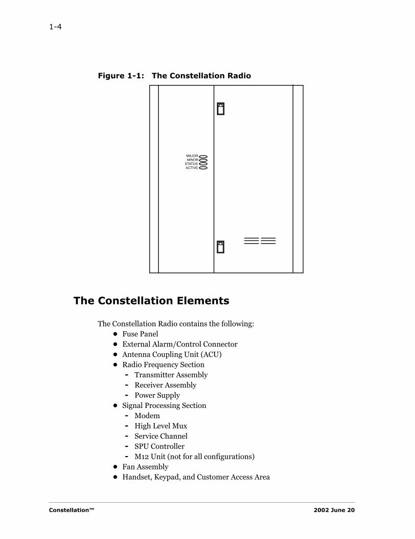
The Constellation Radio is designed with removable doors for easier access to the shelf and card cage. The alarm LEDs can also be observed without opening the doors. See Figure 1-1.
Harris Corporation Constellation™
1-4
Figure 1-1: The Constellation Radio
The Constellation Elements
The Constellation Radio contains the following:• Fuse Panel• External Alarm/Control Connector• Antenna Coupling Unit (ACU)• Radio Frequency Section
- Transmitter Assembly- Receiver Assembly- Power Supply
• Signal Processing Section- Modem- High Level Mux- Service Channel- SPU Controller- M12 Unit (not for all configurations)
• Fan Assembly• Handset, Keypad, and Customer Access Area
MAJOR
STATUSACTIVE
MINOR
Constellation™ 2002 June 20
Introduction 1-5
INTR
OD
UC
TIO
N
Rack Size
The Constellation radio can be installed in a standard 19-inch equipment rack.
A fully protected terminal configuration requires 14 RMS (Rack-Mounting Spaces). A repeater can be mounted on a single rack. Refer to the Constellation SAI manual for more information.
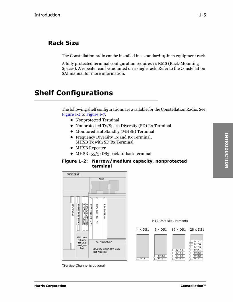
Shelf Configurations
The following shelf configurations are available for the Constellation Radio. See Figure 1-2 to Figure 1-7.
• Nonprotected Terminal• Nonprotected Tx/Space Diversity (SD) Rx Terminal• Monitored Hot Standby (MHSB) Terminal• Frequency Diversity Tx and Rx Terminal,
MHSB Tx with SD Rx Terminal• MHSB Repeater• MHSB 155/3xDS3 back-to-back terminal
Figure 1-2: Narrow/medium capacity, nonprotected terminal
M12 7M12 6
8 x DS1 28 x DS1
TRAN
SMITTER
A1
REC
EIVER A1
SERVIC
E CH
ANN
EL*SPU
CO
NTR
OLLER
HIG
H LEVEL M
UX 1
MO
DEM
A1
ACU
FUSE PANEL
FAN ASSEMBLY
POW
ER SU
PPLY A1
M12 2M12 1
M12 Unit Requirements
M12 5M12 4M12 3M12 2M12 1
M12 4M12 3M12 2M12 1
16 x DS1
M12 Units not used for DS3
configura-tion
M12 1
4 x DS1
KEYPAD, HANDSET, AND DS1 ACCESS
*Service Channel is optional.
Harris Corporation Constellation™
1-6
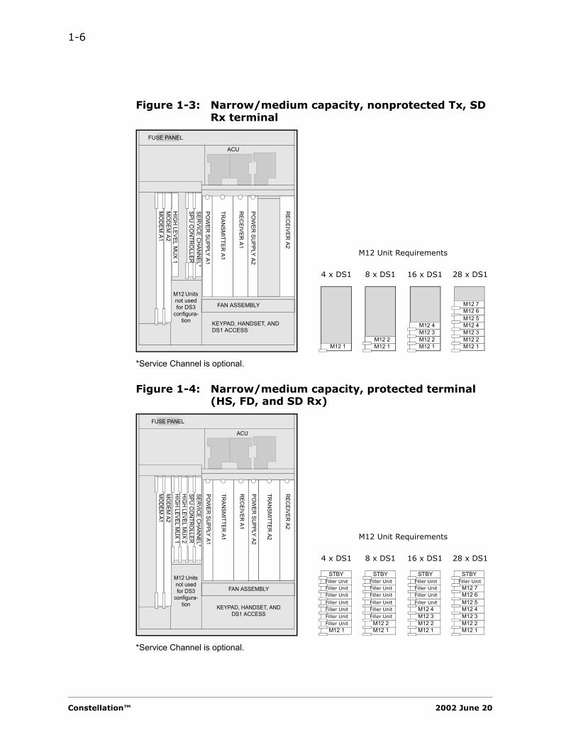
Figure 1-3: Narrow/medium capacity, nonprotected Tx, SD Rx terminal
Figure 1-4: Narrow/medium capacity, protected terminal (HS, FD, and SD Rx)
M12 7M12 6
8 x DS1 28 x DS1
TRAN
SMITTER
A1
REC
EIVER A1
SERVIC
E CH
ANN
EL*SPU
CO
NTR
OLLER
HIG
H LEVEL M
UX 1
MO
DEM
A1
ACU
FUSE PANEL
FAN ASSEMBLY
POW
ER SU
PPLY A1
M12 2M12 1
M12 Unit Requirements
M12 5M12 4M12 3M12 2M12 1
M12 4M12 3M12 2M12 1
16 x DS1
M12 Units not used for DS3
configura-tion
M12 1
4 x DS1
KEYPAD, HANDSET, AND DS1 ACCESS
*Service Channel is optional.
MO
DEM
A2
POW
ER SU
PPLY A2
REC
EIVER A2
M12 1Filler UnitFiller UnitFiller UnitFiller Unit
Filler UnitFiller Unit
Filler UnitSTBY
M12 1M12 2
Filler UnitFiller UnitFiller Unit
Filler UnitFiller Unit
Filler UnitSTBY
M12 1M12 2M12 3M12 4
Filler Unit
Filler UnitFiller Unit
Filler UnitSTBY
M12 1M12 2M12 3M12 4M12 5
M12 7M12 6
8 x DS1 28 x DS1
TRAN
SMITTER
A1
REC
EIVER A1
SERVICE C
HAN
NEL*
SPU C
ON
TROLLER
HIGH
LEVEL MUX 1
MO
DEM
A1
ACU
FUSE PANEL
FAN ASSEMBLY
POW
ER SUPPLY A1 M12 Unit Requirements
16 x DS1
M12 Units not used for DS3
configura-tion
4 x DS1
KEYPAD, HANDSET, AND DS1 ACCESS
*Service Channel is optional.
MO
DEM
A2
POW
ER SUPPLY A2
REC
EIVER A2
TRAN
SMITTER
A2
HIGH
LEVEL MUX 2
Filler UnitSTBY
Constellation™ 2002 June 20
Introduction 1-7
INTR
OD
UC
TIO
N
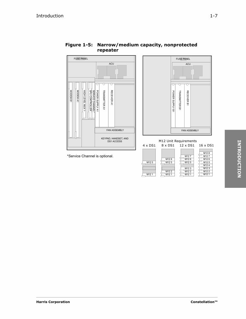
Figure 1-5: Narrow/medium capacity, nonprotected repeater
TRANSM
ITTER A1
RECEIVER A1
SERVICE C
HANN
EL*SPU CO
NTRO
LLER
HIG
H LEVEL M
UX 1
MO
DEM
A1
ACU
FUSE PANEL
FAN ASSEMBLY
POW
ER SU
PPLY A1
TRAN
SMITTER
B1
REC
EIVER B1
ACU
FUSE PANEL
FAN ASSEMBLY
POW
ER SUPPLY B1
KEYPAD, HANDSET, AND DS1 ACCESS
MO
DEM
B1
M12 5
M12 1
M12 6M12 5
M12 2M12 1
M12 7M12 6M12 5
M12 3M12 2M12 1
M12 7M12 6M12 5M12 4M12 3M12 2M12 1
M12 8*Service Channel is optional.
8 x DS1 16 x DS1M12 Unit Requirements
12 x DS14 x DS1
Harris Corporation Constellation™

1-8
Figure 1-6: Narrow/medium capacity, protected repeater
TRAN
SMITTER A1
REC
EIVER A1
ACU
FUSE PANEL
FAN ASSEMBLY
POW
ER SU
PPLY A1
TRANSMITTER
B1
REC
EIVER B1
ACU
FUSE PANEL
FAN ASSEMBLY
POW
ER SU
PPLY B1
KEYPAD, HANDSET, AND DS1 ACCESS
MO
DEM
B1
M12 Unit Requirements for ADM
TRANSM
ITTER A2
REC
EIVER A2
POW
ER SU
PPLY A2
TRAN
SMITTER
B2
REC
EIVER B2
POW
ER SU
PPLY B2
MO
DEM
B2M
OD
EM A1
MO
DEM
A2H
IGH
LEVEL MU
X 1H
IGH
LEVEL MU
X 2
SERVICE C
HAN
NEL*
SPU CON
TROLLER
STBYFiller Unit
M12 B1
M12 A1
STBYFiller Unit
M12 B2M12 B1
M12 A2M12 A1
STBYFiller Unit
M12 B3M12 B2M12 B1
M12 A3M12 A2M12 A1
STBYM12 B4M12 B3M12 B2M12 B1M12 A4M12 A3M12 A2M12 A1
Filler UnitFiller UnitFiller Unit
Filler UnitFiller Unit
Filler Unit
Filler Unit
Filler Unit
Filler Unit
*Service Channel is optional.
8 x DS1 16 x DS112 x DS14 x DS1
Constellation™ 2002 June 20

Introduction 1-9
INTR
OD
UC
TIO
N
Figure 1-1 High capacity, optical and electrical configurations
TRANSM
ITTER A1
RECEIVER A1
SERVICE C
HANNEL**
SPU CONTR
OLLER
HLM
-155 1
HI C
AP MO
DEM
A1
ACU
FUSE PANEL
FAN ASSEMBLY
POW
ER SU
PPLY A1
KEYPAD, HANDSET, AND DS1 ACCESS
Cable Intercon Brkt*
TRAN
SMITTER
A1
REC
EIVER A1
SERVICE C
HAN
NEL**
SPU C
ON
TROLLER
HI C
AP MO
DEM
A1
ACU
FUSE PANEL
FAN ASSEMBLY
POW
ER SUPPLY A1
KEYPAD, HANDSET, AND DS1 ACCESS
Cable Intercon Brkt*
Nonprotected Terminal
HI C
AP MO
DEM
A2HLM
-155 1
RECEIVER A2
POW
ER SU
PPLY A2
Nonprotected Tx, SD Rx Terminal
TRAN
SMITTER
A1
REC
EIVER A1
HI C
AP MO
DEM
A1
ACU
FUSE PANEL
FAN ASSEMBLY
POW
ER SU
PPLY A1
KEYPAD, HANDSET, AND DS1 ACCESS
Cable Intercon Brkt*
HI C
AP MO
DEM
A2H
LM-155 1
TRAN
SMITTER
A2
REC
EIVER A2
POW
ER SU
PPLY A2
HLM
-155 2SPU CO
NTRO
LLERSERVIC
E CHANN
EL**
FD Tx/Rx TerminalMHSB Tx/SD Terminal
*The Cable Interconnection Bracket is for the 155 Electrical system only. It is not installed in the 155 Optical system.**Service Channel is optional.
Harris Corporation Constellation™
1-10
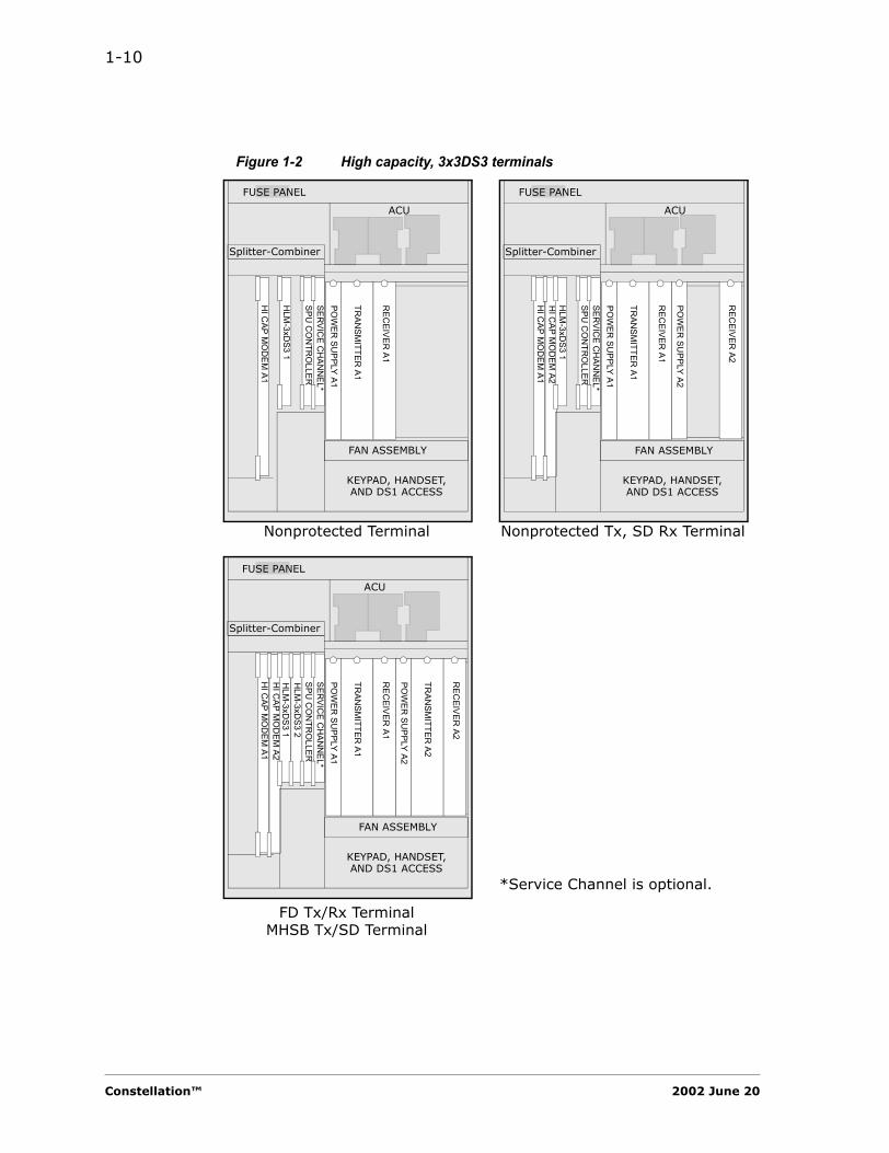
Figure 1-2 High capacity, 3x3DS3 terminals
TRAN
SMITTER
A1
REC
EIVER A1
SERVIC
E CH
ANN
EL*SPU
CO
NTR
OLLER
HLM
-3xDS3 1
HI C
AP MO
DEM
A1
ACU
FUSE PANEL
FAN ASSEMBLY
POW
ER SU
PPLY A1
KEYPAD, HANDSET, AND DS1 ACCESS
Splitter-CombinerTR
ANSM
ITTER A1
REC
EIVER A1
SERVIC
E CH
ANN
EL*SPU
CO
NTR
OLLER
HI C
AP MO
DEM
A1
ACU
FUSE PANEL
FAN ASSEMBLY
POW
ER SU
PPLY A1
KEYPAD, HANDSET, AND DS1 ACCESS
Splitter-Combiner
Nonprotected Terminal
HI C
AP MO
DEM
A2H
LM-3xD
S3 1
REC
EIVER A2
POW
ER SU
PPLY A2
Nonprotected Tx, SD Rx TerminalTR
ANSM
ITTER A1
REC
EIVER A1
HI C
AP MO
DEM
A1
ACU
FUSE PANEL
FAN ASSEMBLY
POW
ER SU
PPLY A1
KEYPAD, HANDSET, AND DS1 ACCESS
Splitter-Combiner
HI C
AP MO
DEM
A2H
LM-3xD
S3 1
TRAN
SMITTER
A2
REC
EIVER A2
POW
ER SU
PPLY A2
HLM
-3xDS3 2
SPU C
ON
TRO
LLERSER
VICE C
HAN
NEL*
FD Tx/Rx TerminalMHSB Tx/SD Terminal
*Service Channel is optional.
Constellation™ 2002 June 20
Introduction 1-11
INTR
OD
UC
TIO
N
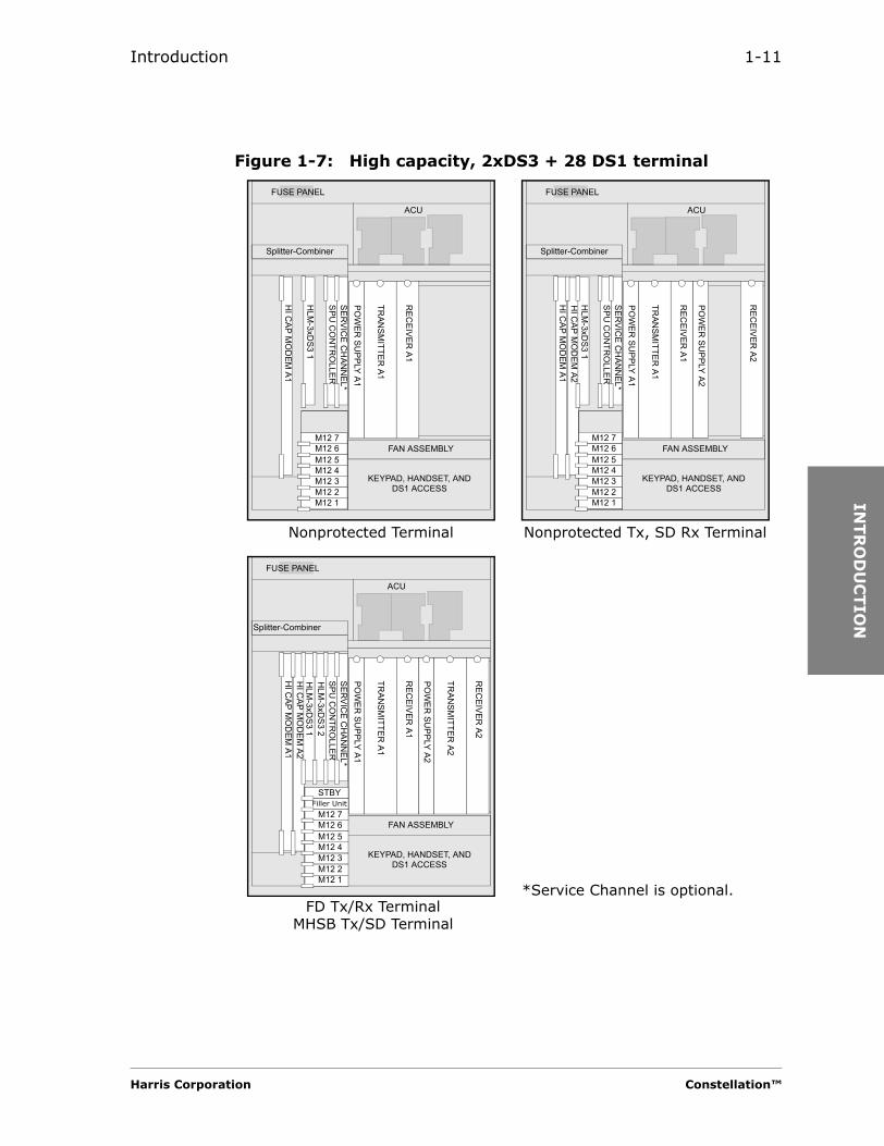
Figure 1-7: High capacity, 2xDS3 + 28 DS1 terminal
TRAN
SMITTER
A1
REC
EIVER A1
SERVIC
E CH
ANN
EL*SPU
CO
NTR
OLLER
HLM
-3xDS3 1
HI C
AP MO
DEM
A1
ACU
FUSE PANEL
FAN ASSEMBLY
POW
ER SU
PPLY A1
KEYPAD, HANDSET, AND DS1 ACCESS
Splitter-Combiner
TRAN
SMITTER
A1
REC
EIVER A1
SERVIC
E CH
ANN
EL*SPU
CO
NTR
OLLER
HI C
AP MO
DEM
A1
ACU
FUSE PANEL
FAN ASSEMBLY
POW
ER SU
PPLY A1
KEYPAD, HANDSET, AND DS1 ACCESS
Splitter-Combiner
Nonprotected Terminal
HI C
AP MO
DEM
A2H
LM-3xD
S3 1
REC
EIVER A2
POW
ER SU
PPLY A2
Nonprotected Tx, SD Rx Terminal
TRAN
SMITTER
A1
REC
EIVER A1
HI C
AP MO
DEM
A1ACU
FUSE PANEL
FAN ASSEMBLY
POW
ER SU
PPLY A1
KEYPAD, HANDSET, AND DS1 ACCESS
Splitter-Combiner
HI C
AP MO
DEM
A2H
LM-3xD
S3 1
TRAN
SMITTER
A2
REC
EIVER A2
POW
ER SU
PPLY A2
HLM
-3xDS3 2
SPU C
ON
TRO
LLERSER
VICE C
HAN
NEL*
FD Tx/Rx TerminalMHSB Tx/SD Terminal
M12 7M12 6M12 5M12 4M12 3M12 2M12 1
M12 7M12 6M12 5M12 4M12 3M12 2M12 1
STBYFiller Unit
M12 7M12 6M12 5M12 4M12 3M12 2M12 1
*Service Channel is optional.
Harris Corporation Constellation™
1-12
Tributary Configuration
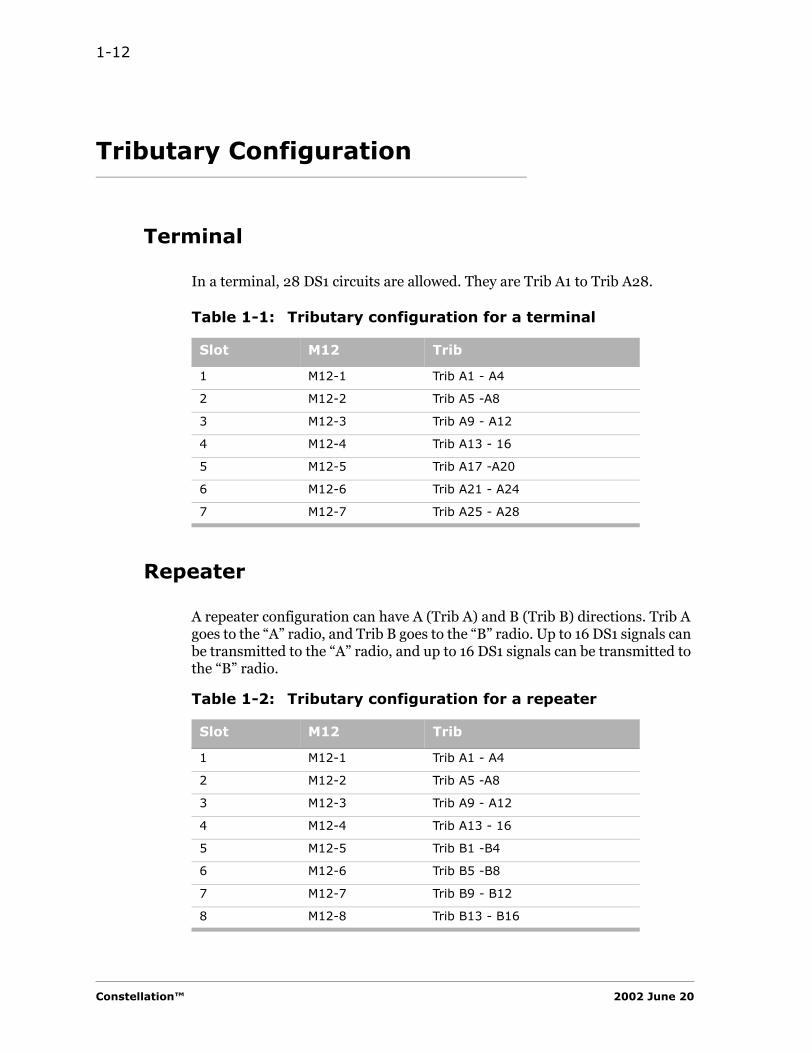
Terminal
In a terminal, 28 DS1 circuits are allowed. They are Trib A1 to Trib A28.
Repeater
A repeater configuration can have A (Trib A) and B (Trib B) directions. Trib A goes to the “A” radio, and Trib B goes to the “B” radio. Up to 16 DS1 signals can be transmitted to the “A” radio, and up to 16 DS1 signals can be transmitted to the “B” radio.
Table 1-1: Tributary configuration for a terminal
Slot M12 Trib
1 M12-1 Trib A1 - A4
2 M12-2 Trib A5 -A8
3 M12-3 Trib A9 - A12
4 M12-4 Trib A13 - 16
5 M12-5 Trib A17 -A20
6 M12-6 Trib A21 - A24
7 M12-7 Trib A25 - A28
Table 1-2: Tributary configuration for a repeater
Slot M12 Trib
1 M12-1 Trib A1 - A4
2 M12-2 Trib A5 -A8
3 M12-3 Trib A9 - A12
4 M12-4 Trib A13 - 16
5 M12-5 Trib B1 -B4
6 M12-6 Trib B5 -B8
7 M12-7 Trib B9 - B12
8 M12-8 Trib B13 - B16
Constellation™ 2002 June 20
Introduction 1-13
INTR
OD
UC
TIO
N
System Features
Protection Switching
The Constellation Radio can be configured with the following protection system.
• Transmitter Assembly• Receiver Assembly• Power Supply• Modem/High Capacity Modem• High Level Mux/High Level 155 Mux/High Level 3xDS3 Mux• M12 Units
The primary set is operating, while the other set is operating in a monitored hot standby (MHSB). When one of the units in the radio shelf fails, the SPU Controller implements an automatic switching algorithm. Switching is nonrevertive; that is, when a failed unit is replaced by a working one, an automatic switching from the standby unit to the working unit does not occur. The exception is the M12 Unit protection, whose nonrevertive or revertive mode can be selected through the Keypad.
All units except the M12 Units are 1+1 protected. M12 Units are 1:N protected.
If one (or more) T1 channel fails on an online M12 Unit, all 4 of those channels are switched to the standby M12 Unit. This switching action causes a momentary disruption of traffic on all 4 of the T1 channels.
The HLM provides errorless switching for the receive paths. Although errorless switching is provided on all MHSB radios, its primary purpose is for space diversity receivers. Switching several times a day is normal for space diversity receivers. Receiver switching is errorless with up to 200 ns of delay between receivers.
Automatic Transmitter Power Control (ATPC)
ATPC with Model 1, 2, and 3
Full ATPC functionality is a supported feature of Transmitter Assemblies, Model 3 and higher, and has a guaranteed 10 dB range. ATPC is not supported for Model 1 and Model 2 Transmitter Assemblies.
Refer to Appendix E for identifying the model numbers.
Harris Corporation Constellation™

1-14
ATPC Functionality
With the ATPC feature enabled, the Transmitter Assembly operates at a reduced power level output of 10 dB below nominal level during normal operation.
When the RSL (Received Signal Level) at the far-end Receiver drops below a predetermined threshold, a request for increased transmitter power is sent upstream to the Transmitter. For a maximum of 5 minutes, the Transmitter increases the output power to full power by approximately 10 dB.
When a fade condition no longer exists (or 5 minutes have passed), the Transmitter will return to the reduced power level output of 10 dB below nominal level.
ATPC can be enabled or disabled through the Keypad.
Software Updates
The download program stores run-time software in the SPU Controller. This downloading can be done either directly at the local site or remotely from a distant site.
Replaceable Modules
Plug and play enables the user to remove a field-replaceable module from service and then replace (or restore) the module without needing to reprogram the user-configurable settings. All modules in the Signal Processing section can be removed and replaced without turning off the power.
Alarm Reporting
The following alarm system is supported:• Fault LEDs• Online LEDs• Local status LEDs• External control relay and customer external alarm inputs
Constellation™ 2002 June 20

Introduction 1-15
INTR
OD
UC
TIO
N
Add-drop Multiplexer Configuration
DS1 Configuration
At a repeater, T1 tributaries may be dropped in groups of 4 T1 lines (T11-4, T15-
8, T19-12, and T113-16).• A direction: M12 slots 1 through 4• B direction: M12 slots 5 through 8
By using the Keypad command, each dropped T2 group may be assigned to any of the 4 M12 slots.
The protection M12 Unit protects the A and B direction slots.
3DS3 Configuration
For a Constellation Radio with an HLM-3xDS3 unit, any selected DS3 can be used to access 28xDS1 signals.
For back-to-back terminals, one of the DS3 channels can be selected for a limited add-drop configuration. In this mode, M12 Units are needed only for DS1 signals (in groups of 4) that are dropped or inserted; up to 16 DS1 signals can be dropped/inserted in each direction. Any DS1 signals that are not dropped are passed to the other terminal via the DS3 cables. DS1 signals may only be passed through in this mode for up to 5 hops before they are terminated.
Harris Corporation Constellation™
1-16
Network Management and Control
Network Management InterfacesThe Constellation Radio offers versatile open network management with an embedded SNMP agent and compatibility with Harris’ NetBoss, StarView, or FarScan network management platforms.
Refer to the following manuals for more information.• FarScan for Windows• NetBoss• StarView Element Management System
Craft InterfaceThe Constellation also supports a Keypad interface. The Keypad can be used for local (per hop) monitoring of alarms and statuses, and for provisioning the network elements. The Keypad allows the customer to quickly configure a system or diagnose a trouble on a hop.
In place of a Keypad, the customer can connect a terminal (VT100-compatible) or a laptop with terminal emulator software to communicate with the Constellation radio.
Constellation™ 2002 June 20

GEN
ER
AL
INFO
RM
ATIO
N
C H A P T E R
2GENERAL INFORMATION
Safety Warnings
The installation, maintenance, or removal of radio equipment (including grounding) and the radio antenna system must be performed by qualified personnel.
Harris MCD is not responsible or liable for the improper performance of the equipment, damage to the equipment, or injury to personnel caused by improper practices.
The following general safety precautions must be observed at all times.• Heed all warning labels that are permanently affixed to the equipment.
Failure to heed warnings can result in serious injury to the equipment and/or user.
• Observe all laser, optical, and RF precautions.• Observe all electrical precautions.• Verify that the grounding configuration complies with local code
practice and requirements.
Harris Corporation Constellation™
2-2
Personal Safety
RADIATION-FREQUENCY RADIATION HAZARD
Do not open waveguide with RF power on.
Do not connect power to the radio assembly unless the transmitter is properly terminated. The transmitter is terminated when its output is connected to the antenna, to test equipment, or to a dummy load.
Only properly trained personnel should operate this equipment.
Verify grounding before the electrical power source is connected to the equipment.
Do not look into optical connectors. Invisible laser light emitted from optical sources can cause permanent eye injury.
Constellation™ 2002 June 20

General Information 2-3
GEN
ER
AL
INFO
RM
ATIO
N
Equipment Safety
Handling Static-sensitive Devices
Some of the components in the Constellation radio are sensitive to static electricity, or electrostatic discharge (ESD) and thus can be damaged or destroyed by ESD that builds up in your body through routine activity. ESD-sensitive components are marked with one of the following symbols:
Before working on the Constellation, discharge any static electricity you may be carrying. Handle the equipment in a static-free environment and use a grounding wrist strap or a heel strap.
Handling Connectors
Avoid touching the edge connectors with your fingers.
Do not touch the optical connector face with your fingers.
Long-term Storage
The Constellation contains moisture-sensitive devices (MSDs) that are shipped in vacuum-sealed packages for protection. Moisture can build up in the MSDs when they are not powered up or not in active use and thus damage sensitive components.
• Store MSDs that are not being used in a dry place.• Rotate the MSDs every two years.
Harris Corporation Constellation™

2-4
Regulatory Compliance (USA)
FCC Title 47, Part 101
This equipment requires licensing for operation under FCC Title 47, Part 101.
FCC Part 15 Emission Requirements
This equipment generates, uses, and can radiate radio frequency energy, and if not installed and used in accordance with this instruction manual, may cause interference to radio communications. It has been tested and found to comply with the limits for a Class A computing device pursuant to Subpart B of Part 15 of the FCC Rules, which are designed to provide reasonable protection against such interference when it is operated in a commercial environment. Operation of this equipment in a residential area is likely to cause interference, in which case the user of the Constellation radio, at the user’s own expense, is required to take whatever measures may be required to correct the interference. The test results show that properly shielded cables are required to maintain compliance with the Class A limits for radiated emissions.
Constellation™ 2002 June 20

SIT
E P
REP
AR
C H A P T E R
3SITE PREPARATION
Power Source
DC power source, 20 V to 60 V.
Equipment Rack Location
The equipment rack should be located in a sheltered area that provides proper lighting, ventilation, and access to both the front and back of the Constellation radio.
At least 3 feet of space must be between the equipment, strong magnetic fields, and sources of impulse noise.
Equipment Inspection
Verify that the correct radio system is going to be installed.• Each Constellation radio has been set up at the factory according to the
customer’s specifications. To configure a radio for a different application, contact the Harris MCD Technical Assistance Center (TAC). See page 1.
• The Constellation radio is shipped fully assembled and ready to install.
Harris Corporation Constellation™
ATIO
N

3-2
Unpacking Procedure
1. Check all packaging for external damage; report any external damage to the carrier. If damage is noted, a shipping carrier agent should be present for unpacking and inspecting the remaining contents.
2. Open and check each package against the bill of material. If any items are missing, contact Harris MCD’s Customer Support. The Customer Support information is found at the beginning of this manual.
3. Do not remove equipment from antistatic packaging until immediately before installation.
4. Ensure that the connectors are undamaged.
5. Ensure that all plug-in units are firmly seated.
6. Ensure that the cable connections are undamaged and secure.
Constellation™ 2002 June 20

INS
TA
LLA
TIO
N A
ND
C
OM
MIS
SIO
NIN
G
C H A P T E R
4INSTALLATION AND
COMMISSIONING
Introduction
FCC Requirements
The Federal Communications Commission (FCC) requires that records of transmitter measurements be maintained.
Data and Records
The Constellation radio is set up, aligned, and tested at the factory. You will need the following for putting the radio into service.
• Factory/Field Test Data (in the Sales Order Specific Information binder).
• Constellation Routine Maintenance Log form.See Appendix F for an example of this form.
Harris Corporation Constellation™
4-2
Precaution
Do not turn on the power to the radio until directed.
Recommended Tools and Test Equipment
Customer-supplied Tools
Table 4-1 lists the customer-supplied tools needed for installation of the Constellation radio.
Recommended Test Equipment for Installation and Maintenance
Table 4-2 lists the recommended test equipment required to test the Constellation radio.
Table 4-1: Customer-supplied tools
Tools
Antistatic wrist or heel strap
Cable ties and cable-tie installation tool
Basic hand tools
Cable for powering and grounding the rack
Constellation™ 2002 June 20
Installation and Commissioning 4-3
INS
TA
LLA
TIO
N A
ND
C
OM
MIS
SIO
NIN
G
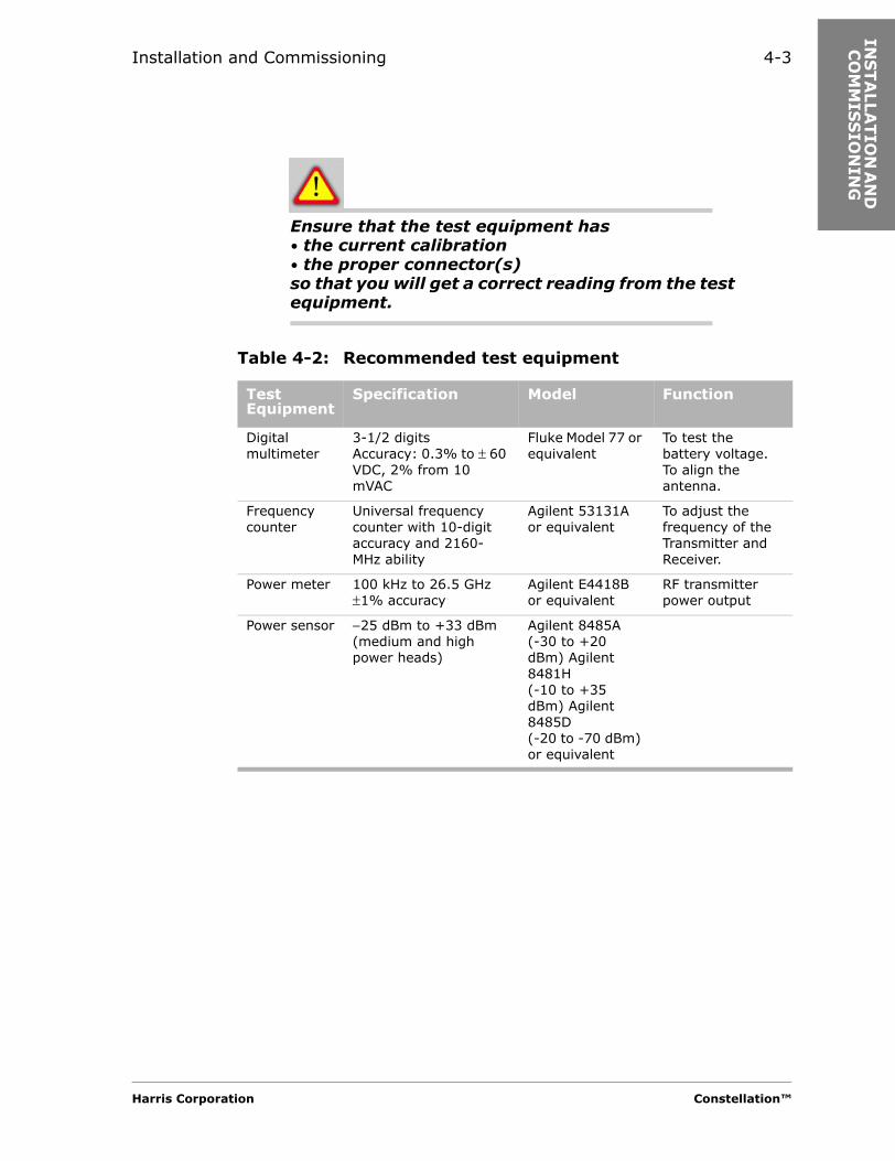
Ensure that the test equipment has • the current calibration• the proper connector(s)so that you will get a correct reading from the test equipment.
Table 4-2: Recommended test equipment
Test Equipment
Specification Model Function
Digital multimeter
3-1/2 digitsAccuracy: 0.3% to ± 60 VDC, 2% from 10 mVAC
Fluke Model 77 or equivalent
To test the battery voltage.To align the antenna.
Frequency counter
Universal frequency counter with 10-digit accuracy and 2160-MHz ability
Agilent 53131A or equivalent
To adjust the frequency of the Transmitter and Receiver.
Power meter 100 kHz to 26.5 GHz ±1% accuracy
Agilent E4418B or equivalent
RF transmitter power output
Power sensor −25 dBm to +33 dBm (medium and high power heads)
Agilent 8485A(-30 to +20 dBm) Agilent 8481H(-10 to +35 dBm) Agilent 8485D(-20 to -70 dBm) or equivalent
Harris Corporation Constellation™

4-4
Circuit Breakers
The values in Table 4-3 are for the Constellation terminal radio only.
Grounding Recommendations
Grounding in accordance with the R56 installation standard is necessary for proper operation of the equipment as well as protection of the personnel and equipment.
• Connect the ground between the radio rack and halo, or ground window of the site.
• Do not connect the ground through any other radio or rack.• Do not daisy chain the grounds. A surge through a daisy chain ground
will go through all the radios.• The return bus bar should be grounded using 6-AWG wire as a
minimum.
Some operators require the same gauge wire for the return buss bar and the battery cables. This may help avoid DC power surges when the on-site generator switches between on or off.
Table 4-3: Recommended circuit breaker sizes for Constellation radio terminal only
6, 7/8 GHz 10/11 GHz
Configuration 24 V 48 V 24 V 48 V
Fully protected 25 A 15 A 30 A 15 A
Constellation™ 2002 June 20
Installation and Commissioning 4-5
INS
TA
LLA
TIO
N A
ND
C
OM
MIS
SIO
NIN
G
Monitoring Recommendations
It is important that you use high-quality adapters when monitoring power output at the radio monitor port. Inexpensive “screw together” adapters introduce unpredictable amounts of signal loss. Attempting to compensate for this signal loss can result in sync loss and errored seconds events.
Monitoring the Reference Frequency
Harris recommends monitoring the reference frequency during installation, and then at least once a year while the radio is in service.
The specification for the oscillator is +/- 300 Hz. The reference oscillator frequency can be adjusted through the Keypad. If it cannot be adjusted within 300 Hz, the OCXO should be replaced.
Performing routine checks and recording any adjustments can expose a potential crystal problem before there is a failure. Changes in crystal frequency are most likely in the first few months of operation. After three to six months, the crystal should stabilize.
UBER Measurement
UBER (uncorrected bit error ratio) is a measurement that shows BER before FEC takes place. UBER command can be accessed through the Keypad’s hidden Measurement submenu.
Harris Corporation Constellation™

4-6
Summary of the Installation Procedures
Table 4-4 is a summary of the installation procedures.
Turning on the Radio
Table 4-4: Installation procedures
Step Procedure For Details, Go To
1 Ensure that the power breaker is off or that the fuse is removed.
2 Install the Constellation Radio rack as specified in the Sales Order Specific Information (Engineering Work Order).
3 Ground the radio rack. page 4-9
4 Open and remove the Constellation doors. page 4-9
5 Connect the interconnection cables to the Constellation backplane.
page 4-12
6 Connect the Constellation radio to other equipment. Appendix A
7 Connect the customer-configured alarm wires. page 4-32
8 Connect the Constellation to the antenna or to a dummy load.
page 4-18
9 Test the office battery voltage. page 4-20
10 Connect the battery power wires to the Constellation. page 4-20
Table 4-5: Turn-on procedures
Step Procedure For Details, Go To
1 Ensure that the correct fuses are installed in the Fuse Panel.
page 4-22
Constellation™ 2002 June 20
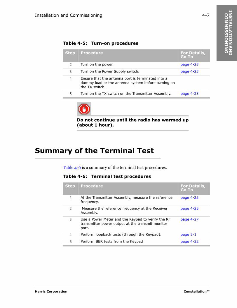
Installation and Commissioning 4-7
INS
TA
LLA
TIO
N A
ND
C
OM
MIS
SIO
NIN
G
Do not continue until the radio has warmed up (about 1 hour).
Summary of the Terminal Test
Table 4-6 is a summary of the terminal test procedures.
2 Turn on the power. page 4-23
3 Turn on the Power Supply switch. page 4-23
4 Ensure that the antenna port is terminated into a dummy load or the antenna system before turning on the TX switch.
5 Turn on the TX switch on the Transmitter Assembly. page 4-23
Table 4-5: Turn-on procedures
Step Procedure For Details, Go To
Table 4-6: Terminal test procedures
Step Procedure For Details, Go To
1 At the Transmitter Assembly, measure the reference frequency.
page 4-23
2 Measure the reference frequency at the Receiver Assembly.
page 4-25
3 Use a Power Meter and the Keypad to verify the RF transmitter power output at the transmit monitor port.
page 4-27
4 Perform loopback tests (through the Keypad). page 5-1
5 Perform BER tests from the Keypad page 4-32
Harris Corporation Constellation™
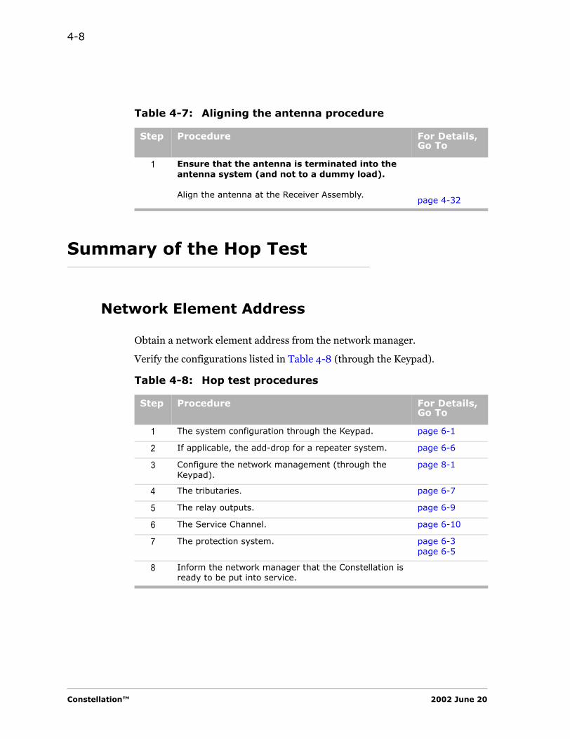
4-8
Summary of the Hop Test
Network Element Address
Obtain a network element address from the network manager.
Verify the configurations listed in Table 4-8 (through the Keypad).
Table 4-7: Aligning the antenna procedure
Step Procedure For Details, Go To
1 Ensure that the antenna is terminated into the antenna system (and not to a dummy load).
Align the antenna at the Receiver Assembly.page 4-32
Table 4-8: Hop test procedures
Step Procedure For Details, Go To
1 The system configuration through the Keypad. page 6-1
2 If applicable, the add-drop for a repeater system. page 6-6
3 Configure the network management (through the Keypad).
page 8-1
4 The tributaries. page 6-7
5 The relay outputs. page 6-9
6 The Service Channel. page 6-10
7 The protection system. page 6-3page 6-5
8 Inform the network manager that the Constellation is ready to be put into service.
Constellation™ 2002 June 20
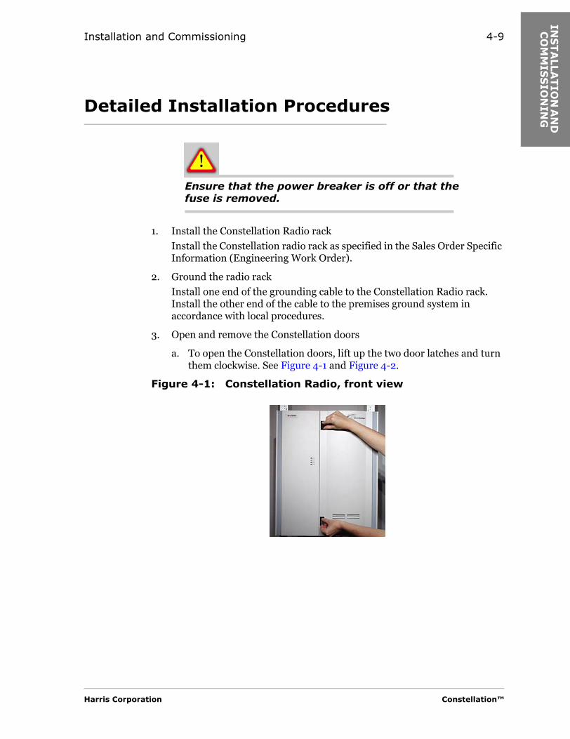
Installation and Commissioning 4-9
INS
TA
LLA
TIO
N A
ND
C
OM
MIS
SIO
NIN
G
Detailed Installation Procedures
Ensure that the power breaker is off or that the fuse is removed.
1. Install the Constellation Radio rack
Install the Constellation radio rack as specified in the Sales Order Specific Information (Engineering Work Order).
2. Ground the radio rack
Install one end of the grounding cable to the Constellation Radio rack. Install the other end of the cable to the premises ground system in accordance with local procedures.
3. Open and remove the Constellation doors
a. To open the Constellation doors, lift up the two door latches and turn them clockwise. See Figure 4-1 and Figure 4-2.
Figure 4-1: Constellation Radio, front view
Harris Corporation Constellation™
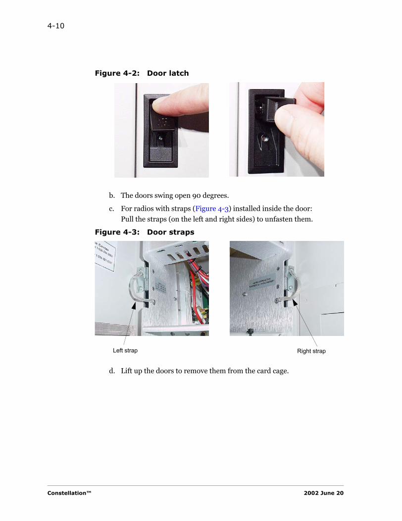
4-10
Figure 4-2: Door latch
b. The doors swing open 90 degrees.
c. For radios with straps (Figure 4-3) installed inside the door:
Pull the straps (on the left and right sides) to unfasten them.
Figure 4-3: Door straps
d. Lift up the doors to remove them from the card cage.
Left strap Right strap
Constellation™ 2002 June 20

Installation and Commissioning 4-11
INS
TA
LLA
TIO
N A
ND
C
OM
MIS
SIO
NIN
G
CAN Connector
Terminal
Ensure that the RJ-45 connector labeled CAN on the Constellation backplane is terminated.
Repeater
Ensure that a cable (087-110251) is installed between the CAN port on the top shelf and the CAN IN port on the repeater shelf as shown in Figure 4-4.
Harris Corporation Constellation™
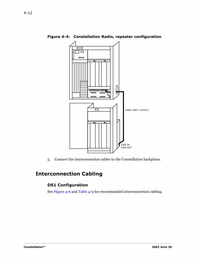
4-12
Figure 4-4: Constellation Radio, repeater configuration
5. Connect the interconnection cables to the Constellation backplane.
Interconnection Cabling
DS1 Configuration
See Figure 4-6 and Table 4-9 for recommended interconnection cabling.
CAN INCAN OUT
Cable (087-110251)
Constellation™ 2002 June 20
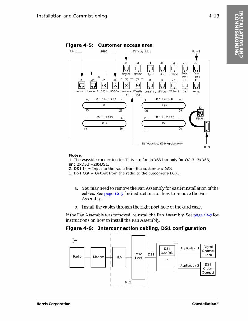
Installation and Commissioning 4-13
INS
TA
LLA
TIO
N A
ND
C
OM
MIS
SIO
NIN
G
Figure 4-5: Customer access area
a. You may need to remove the Fan Assembly for easier installation of the cables. See page 12-5 for instructions on how to remove the Fan Assembly.
b. Install the cables through the right port hole of the card cage.
If the Fan Assembly was removed, reinstall the Fan Assembly. See page 12-7 for instructions on how to install the Fan Assembly.
Figure 4-6: Interconnection cabling, DS1 configuration
Wayside Monitor
VersaT1lity VF Port 1 VF Port 2Wayside Out
WaysideIn
DataPort 2
DS3 OutDS3 InHandset 2Handset 1
Aux EthernetSpur
KeypadCan
Fan
DS1 17-32 Out
DS1 1-16 In
DS1 17-32 In
DS1 1-16 Out FSCAN
DE-9
RJ-45T1 Wayside1
E1 Wayside, SDH option only
RJ-11
26
25
26
25
25
25
26
26
1 1
11
50
50 50
50
BNC
DataPort 1
Notes:1. The wayside connection for T1 is not for 1xDS3 but only for OC-3, 3xDS3, and 2xDS3 +28xDS1.2. DS1 In = Input to the radio from the customer’s DSX.3. DS1 Out = Output from the radio to the customer’s DSX.
J1 J3 J1 J1 J3 J2 J2
J3J2 J3 J3J2 J2 J2 J2 J2 J1 J1
J2J2
J3
P15
P14
Radio Modem HLMM12 Units
DS1or
DS1 Jackfield
DS1 Cross-
Connect
Digital Channel
Bank
Application 1
Application 2
Mux
Harris Corporation Constellation™

4-14
Note: Avaya Communication, 608C cables, or equivalent.
DS3 Configuration
Figure 4-7: Interconnection cabling, DS3 configuration
3xDS3 Configuration
Figure 4-8: Interconnection cabling, 3xDS3 configuration
Table 4-9: Interconnection cabling requirements
Application Cable Length(feet)
Line Attenuation/Equalization
Specifications
1 Digital channel bank
0 to 1310
Programmed through software
22 AWG, 16-pair, tinned copper, twisted pair, solid, shielded, PVC, equipped with drain wire, 100 ohms
2 DS1 cross-connect
0 to 655 22 AWG, 16-pair, tinned copper, twisted pair, solid, shielded, PVC, equipped with drain wire, 100 ohms
Radio Modem HLMDS3
or
DS3 Jackfield
DS3 Radio Repeater
DS3 Multiplexer
Application 1
Application 2
or or
Avaya 734 cables, or equivalent.
Radio Modem HLMDS3-2
or
DS3 Jackfield
DS3 Radio Repeater
DS3 Multiplexer
Application 1
Application 2
or or
DS3-1
DS3-3
Avaya 734 cables, or equivalent.
Constellation™ 2002 June 20
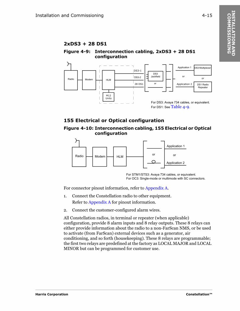
Installation and Commissioning 4-15
INS
TA
LLA
TIO
N A
ND
C
OM
MIS
SIO
NIN
G
2xDS3 + 28 DS1
Figure 4-9: Interconnection cabling, 2xDS3 + 28 DS1 configuration
155 Electrical or Optical configuration
Figure 4-10: Interconnection cabling, 155 Electrical or Optical configuration
For connector pinout information, refer to Appendix A.
1. Connect the Constellation radio to other equipment.
Refer to Appendix A for pinout information.
2. Connect the customer-configured alarm wires.
All Constellation radios, in terminal or repeater (when applicable) configuration, provide 8 alarm inputs and 8 relay outputs. These 8 relays can either provide information about the radio to a non-FarScan NMS, or be used to activate (from FarScan) external devices such as a generator, air conditioning, and so forth (housekeeping). These 8 relays are programmable; the first two relays are predefined at the factory as LOCAL MAJOR and LOCAL MINOR but can be programmed for customer use.
Radio Modem HLMDS3-2
or
DS3 Jackfield
DS1 Radio Repeater
DS3 Multiplexer Application 1
Application 2
oror
DS3-1
M12 Units
28 DS1
For DS3: Avaya 734 cables, or equivalent.For DS1: See Table 4-9.
Radio Modem HLMor
Application 1
Application 2
or
For STM1/STS3: Avaya 734 cables, or equivalent.For OC3: Single-mode or multimode with SC connectors.
Harris Corporation Constellation™
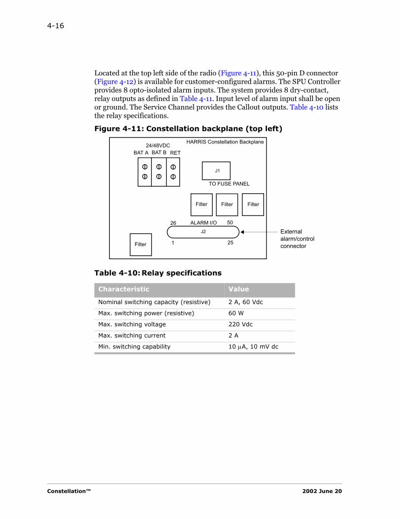
4-16
Located at the top left side of the radio (Figure 4-11), this 50-pin D connector (Figure 4-12) is available for customer-configured alarms. The SPU Controller provides 8 opto-isolated alarm inputs. The system provides 8 dry-contact, relay outputs as defined in Table 4-11. Input level of alarm input shall be open or ground. The Service Channel provides the Callout outputs. Table 4-10 lists the relay specifications.
Figure 4-11: Constellation backplane (top left)
Table 4-10:Relay specifications
Characteristic Value
Nominal switching capacity (resistive) 2 A, 60 Vdc
Max. switching power (resistive) 60 W
Max. switching voltage 220 Vdc
Max. switching current 2 A
Min. switching capability 10 µA, 10 mV dc
BAT A BAT B RET24/48VDC
HARRIS Constellation Backplane
TO FUSE PANEL
ALARM I/O
Filter
Filter Filter Filter
26
1 25
50
External alarm/control connector
J1
J2
Constellation™ 2002 June 20
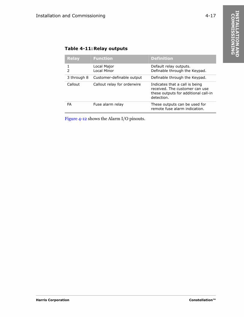
Installation and Commissioning 4-17
INS
TA
LLA
TIO
N A
ND
C
OM
MIS
SIO
NIN
G
Figure 4-12 shows the Alarm I/O pinouts.
Table 4-11:Relay outputs
Relay Function Definition
12
Local MajorLocal Minor
Default relay outputs.Definable through the Keypad.
3 through 8 Customer-definable output Definable through the Keypad.
Callout Callout relay for orderwire Indicates that a call is being received. The customer can use these outputs for additional call-in detection.
FA Fuse alarm relay These outputs can be used for remote fuse alarm indication.
Harris Corporation Constellation™

4-18
Figure 4-12: Alarm I/O pinouts, J2 (D connector, female)
3. Connect the Constellation Radio to the antenna or to a dummy load.
1
26 27 28
3
29
4
30
5
31
6
32
7
33
8
34
9
35
10
36
11
37
12
38
13
39
14
40
15 1716 18
41 4442 43
19 20
45 46 4847
21 22 23 24
49 50
252
Fuse Alarm
Callout Relay
Fan AlarmMajor Alarm
(default)
Minor Alarm
(default)
RELA
Y 1
NC
RELA
Y 1
NO
RELA
Y 1
CO
MRELA
Y 2
CO
MRELA
Y 2
NC
RELA
Y 2
NO
RELA
Y 4
NC
RELA
Y 4
NO
RELA
Y 4
CO
MRELA
Y 3
CO
MRELA
Y 3
NC
RELA
Y 3
NO
RELA
Y 5
NC
RELA
Y 5
NO
RELA
Y 5
CO
MN
CRELA
Y 7
CO
MRELA
Y 7
NO
RELA
Y 7
NC
NC
NC
NC
NC
EXT A
LARM
1G
ND
EXT A
LARM
2N
CEXT A
LARM
3FA
N A
LM R
ELA
Y N
OEXT A
LARM
4FA
N A
LM R
ELA
Y C
OM
EXT A
LARM
5FA
N A
LM R
ELA
Y N
CEXT A
LARM
6N
CEXT A
LARM
7N
CEXT A
LARM
8CALL
OU
T R
LY N
CFA
RELA
Y N
CRELA
Y 6
NC
RELA
Y 8
NC
RELA
Y 6
CO
MRELA
Y 6
NO
CALL
OU
T R
LY C
OM
CALL
OU
T R
LY N
OFA
RELA
Y C
OM
FA R
ELA
Y N
ORELA
Y 8
CO
MRELA
Y 8
NO
Constellation™ 2002 June 20

Installation and Commissioning 4-19
INS
TA
LLA
TIO
N A
ND
C
OM
MIS
SIO
NIN
G
a. Verify that the antenna waveguide is grounded according to recommended or regulatory practice.
b. Determine and prepare the length(s) of flexible waveguide needed to connect the antenna(s) to the radio.
c. Install the waveguide.
d. Remove the Port Cover from the ACU. See Figure 4-13.
Table 4-12:ACU technical data
Ports
Antenna port
6 GHz CMR-137 flange with all tapped mounting holes for No. 6-32 screws.
CPR-137 spacer adapter
7/8 GHz CMR-112 flange with all tapped mounting holes for No. 6-32 screws.
CPR-112 spacer adapter
10/11 GHz
UG39/U flange with all tapped mounting holes for No. 8-32 screws.
CPR-90 spacer adapter
Expansion port
6 GHz CMR-137 flange with all tapped mounting holes for No. 6-32 screws.
The waveguide termination can be removed to gain access to this port. Optional waveguide pieces to interface to other radios are available upon request.
7/8 GHz CMR-112 flange with all tapped mounting holes for No. 6-32 screws.
10/11 GHz
UG39/U flange with all tapped mounting holes for No. 8-32 screws.
Transmit monitor port SMA female connector. A calibrated monitor port, approximately −30 dB down from the top of rack.The exact number is on the label “Coupling loss from antenna flange”.
Transmit RF in SMA female connector.
Receive RF out SMA female connector.
Harris Corporation Constellation™
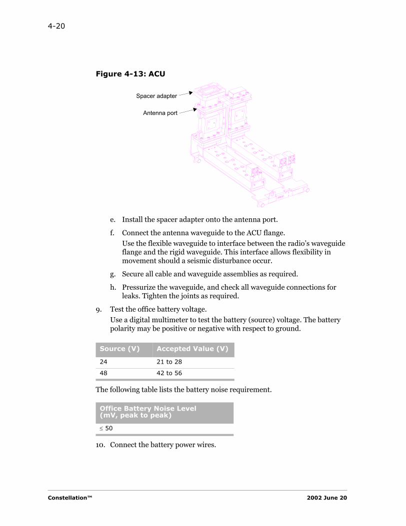
4-20
Figure 4-13: ACU
e. Install the spacer adapter onto the antenna port.
f. Connect the antenna waveguide to the ACU flange.
Use the flexible waveguide to interface between the radio’s waveguide flange and the rigid waveguide. This interface allows flexibility in movement should a seismic disturbance occur.
g. Secure all cable and waveguide assemblies as required.
h. Pressurize the waveguide, and check all waveguide connections for leaks. Tighten the joints as required.
9. Test the office battery voltage.
Use a digital multimeter to test the battery (source) voltage. The battery polarity may be positive or negative with respect to ground.
The following table lists the battery noise requirement.
10. Connect the battery power wires.
Source (V) Accepted Value (V)
24 21 to 28
48 42 to 56
Office Battery Noise Level(mV, peak to peak)
≤ 50
Antenna port
Spacer adapter
Constellation™ 2002 June 20

Installation and Commissioning 4-21
INS
TA
LLA
TIO
N A
ND
C
OM
MIS
SIO
NIN
G
Harris recommends a separate fuse or circuit breaker for Battery A and Battery B.
Circuit breaker or fuse, if used, should be turned off or removed prior to connection of power wires.
Power Runs.
The appropriate gauge wire should be used for the distance of each power run. Harris recommends the following wire specifications for power runs (Table 4-13).
a. Ensure that all the fuses in the fuse panel are in place.
Ensure that the power breaker is off.
b. Connect the battery power wires.• If the radio is shipped in a rack, use the drawings in the sales order
specific information.• If the radio is shipped loose, continue with this step.
Terminal. • See Figure 4-14 for wiring specifications.• See Table 4-13 for recommended wiring sizes.
Table 4-13:Wire specifications for power runs
Power Run Wire Color Wire Size (AWG)
Battery A Red 8
Battery B White 8
DC return Black 6
Ground Green 6
Harris Corporation Constellation™

4-22
Figure 4-14: Constellation backplane, terminal
Repeater.
Connect the wires to the quick disconnect tabs behind the Fuse Panel (Figure 4-15).
Figure 4-15: Fuse Panel, repeater
Detailed Turn-on Procedures
1. Ensure that the correct fuses are installed.
BAT A BAT B RET24/48VDC
HARRIS Constellation Backplane
TO FUSE PANEL
ALARM I/O
Filter
Filter Filter Filter
26
1 25
50
Red White Black
J1
J2 External alarm/control connector
DC IN B(P3)
DC IN A(P6)
RETURN(P2)
RedWhite Black
FUSEALARM
Constellation™ 2002 June 20
Installation and Commissioning 4-23
INS
TA
LLA
TIO
N A
ND
C
OM
MIS
SIO
NIN
G
Refer to the fuse chart posted on the fuse panel to ensure that the correct-value fuse is inserted for each plug-in unit.
2. Turn on the power
Turn on the circuit breaker at the main power distribution panel.
The red LED on each plug-in unit should light momentarily and then go off as the green LED lights. The red LED on the M12 Unit will be illuminated until the initialization process is completed.
3. Turn on the Power Supply switch
On the Power Supply faceplate, push the PWR switch to ON.
4. Ensure that the antenna port is terminated into a dummy load or the antenna system before turning on the TX switch.
5. Turn on the TX switch
On the Transmitter Assembly faceplate, push the TX switch to ON (Figure 4-16, page 4-25).
Do not continue until the radio has warmed up (about 1 hour).
Detailed Terminal Test
Refer to Appendix B for Keypad menu tree.
1. Transmitter Frequency Measurement
Harris Corporation Constellation™

4-24
The reason for performing these procedures is to ensure that the Transmitter Assembly is operating on the correct frequency and power level to comply with the license requirements. (Example: FCC Title 47, Part 101.107, 101.111, 101.113, and 101.217.) It also ensures that the residual BER floor and acquisition time remain within specification.
a. Record the operating frequency of the Transmitter from the Keypad hidden menu.
CONFIGURATION > F1 + F3 or Ctrl B > TX FREQ
b. This frequency should match the one written on the Tx filter and the station authorization.
c. Determine from the table in Appendix C, which multiplier-filter should be used (or is in use).
The Transmitter Assembly should be plugged into the rack and powered for at least 30 minutes prior to adjusting the frequency. The position of the TX On/OFF switch does not affect the measurement. The power supply should be ON.
The Frequency Counter should be plugged in and powered for at least 30 minutes prior to adjusting the frequency.
d. Connect a frequency counter to the REF MON port on the Transmitter Assembly (Figure 4-16).
e. To adjust the frequency, use Keypad hidden menu command
CONFIGURATION > F1 + F3 or Ctrl B > TX 100MHZ TUNE
f. Adjust the frequency to
100.000,000 MHz ± (see table)
Year of Operation Tolerance
Initial adjustment ± 100 Hz
After one year of operation ± 200 Hz
Thereafter ± 300 Hz
Constellation™ 2002 June 20

Installation and Commissioning 4-25
INS
TA
LLA
TIO
N A
ND
C
OM
MIS
SIO
NIN
G
Figure 4-16: Transmitter Assembly, front view
7. Measure the REF MON frequency of the Receiver Assembly
a. Record the operating frequency of the Receiver from the Keypad (hidden menu).
CONFIGURATION > F1 + F3 or Ctrl B > RX FREQ
b. This frequency should match the one written on the Rx filter and the station authorization.
c. Determine from the table in Appendix C, which multiplier-filter should be used (or is in use).
Note: To prevent damage to the connectors, do not exceed 8 to 9 in-pounds of torque.
IF IN (from Modem)
RF OUT (to ACU)
Thumb screw (2)
Transmitteroutput level
LO MONLO synthesizer test point(2.060 to 2.160 GHz)(For factory use only)
REF MONReference frequencytest point(100 MHz)
ON/OFF switch, turns the power amplifier on or off
FAULT (red LED)
ON LINE (green LED)
TSL
GND
Handle
Caution: When measuring Tx power at RF OUT, over torquing may cause damage.For on-line Tx, use monitor port at front of ACU.Refer to product documentation.
Harris Corporation Constellation™

4-26
d. Connect a frequency counter to the REF MON port on the Receiver Assembly (Figure 4-16).
e. To adjust the frequency, use the Keypad hidden-menu command
CONFIGURATION > F1 + F3 or Ctrl B > RX 100MHZ TUNE
f. Adjust the frequency to
100.000,000 MHz ± (see table)
Year of Operation Tolerance
Initial adjustment ± 100 Hz
After one year of operation ± 200 Hz
Thereafter ± 300 Hz
Constellation™ 2002 June 20
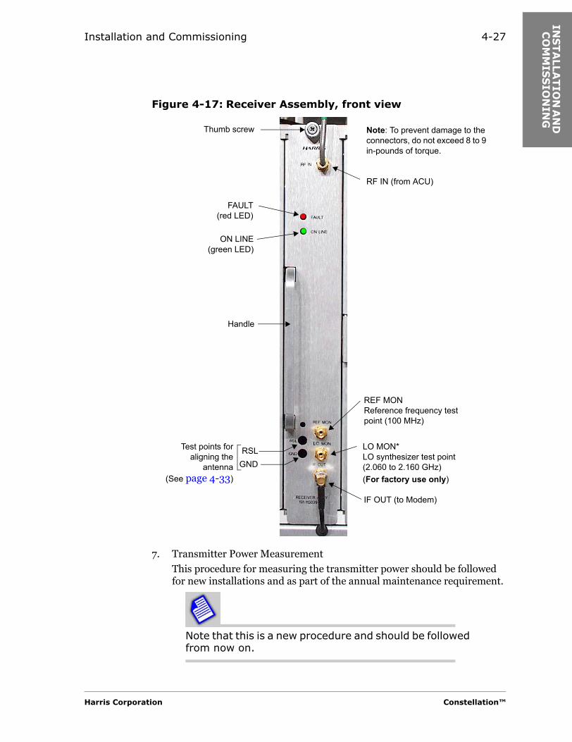
Installation and Commissioning 4-27
INS
TA
LLA
TIO
N A
ND
C
OM
MIS
SIO
NIN
G
Figure 4-17: Receiver Assembly, front view
7. Transmitter Power Measurement
This procedure for measuring the transmitter power should be followed for new installations and as part of the annual maintenance requirement.
Note that this is a new procedure and should be followed from now on.
Note: To prevent damage to the connectors, do not exceed 8 to 9 in-pounds of torque.
RF IN (from ACU)
IF OUT (to Modem)
Thumb screw
REF MON Reference frequency test point (100 MHz)
Test points foraligning the
antenna(See page 4-33)
FAULT(red LED)
ON LINE(green LED)
RSLGND
Handle
LO MON*LO synthesizer test point(2.060 to 2.160 GHz)(For factory use only)
Harris Corporation Constellation™
4-28
You may observe a low output alarm while you are performing calibration. Ignore the alarm until the calibration has been completed.
Measuring the Power Output of an Off-line Transmitter.
If the Transmitter to be measured is off-line, then it must be placed on line.
The following procedure interrupts traffic.
a. Lock the Transmitter on line as follows:
From the Keypad main menu, select
CONTROL > LOCK/IF LPBK > LOCK MOD/TX > SET
Connecting the Power Meter.
b. Connect the power head of the power meter to the transmit monitor port on the ACU. See Figure 4-18.
The monitor port is labeled “COUPLING LOSS FROM ANTENNA FLANGE CAL AT XMT FREQ __._”.
Constellation™ 2002 June 20
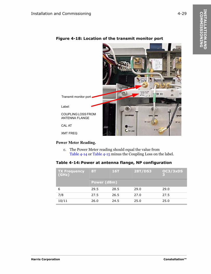
Installation and Commissioning 4-29
INS
TA
LLA
TIO
N A
ND
C
OM
MIS
SIO
NIN
G
Figure 4-18: Location of the transmit monitor port
Power Meter Reading.
c. The Power Meter reading should equal the value from Table 4-14 or Table 4-15 minus the Coupling Loss on the label.
Table 4-14:Power at antenna flange, NP configuration
TX Frequency(GHz)
8T 16T 28T/DS3 OC3/3xDS3
Power (dBm)
6 29.5 28.5 29.0 29.0
7/8 27.5 26.5 27.0 27.5
10/11 26.0 24.5 25.0 25.0
Label:
COUPLING LOSS FROM ANTENNA FLANGE
CAL AT
XMT FREQ
Transmit monitor port
Harris Corporation Constellation™
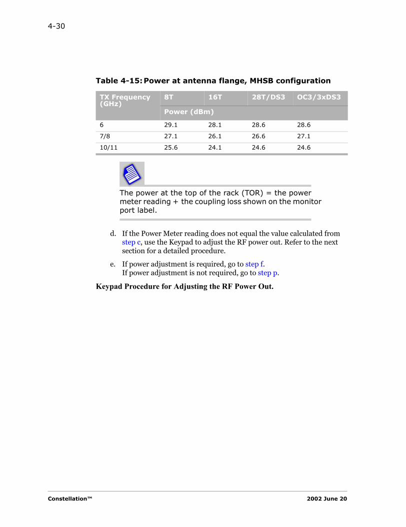
4-30
The power at the top of the rack (TOR) = the power meter reading + the coupling loss shown on the monitor port label.
d. If the Power Meter reading does not equal the value calculated from step c, use the Keypad to adjust the RF power out. Refer to the next section for a detailed procedure.
e. If power adjustment is required, go to step f.If power adjustment is not required, go to step p.
Keypad Procedure for Adjusting the RF Power Out.
Table 4-15:Power at antenna flange, MHSB configuration
TX Frequency(GHz)
8T 16T 28T/DS3 OC3/3xDS3
Power (dBm)
6 29.1 28.1 28.6 28.6
7/8 27.1 26.1 26.6 27.1
10/11 25.6 24.1 24.6 24.6
Constellation™ 2002 June 20
Installation and Commissioning 4-31
INS
TA
LLA
TIO
N A
ND
C
OM
MIS
SIO
NIN
G
Note that this procedure requires access to the hidden RF Configuration submenu.
f. Ensure that the Transmitter on line is locked.
From the Keypad main menu, select
CONTROL > LOCK/IF LPBK > LOCK MOD/TX > SET
g. For the high power calibration, access the hidden RF Configuration submenu from the Keypad main menu.
CONFIGURATION > F1 + F3 or Ctrl B > TX PWR CALIB > ADJUST HIGH PWR
h. Use the UP/DOWN keys until the value = the power meter reading + the coupling loss shown on the monitor port label.
i. Go to HIGH PWR CALIB, and enter the value from step h.
Notes:
• Use the F2 key for the decimal point.
• You must enter 3 digits. For example, 30 dBm is entered as 30.0.
j. Exit.
k. Go to ADJUST LOW PWR.
l. Use the UP/DOWN keys until the value = the power meter reading + the coupling loss shown on the monitor port label.
Notes:
• Tx Assy, Model 2: should be approximately 5 dB below high power
• Tx Assy, Model 3: should be approximately 10 dB below high power
Adjust if necessary.
m. Go to LOW PWR CALIB, and enter the value from step l.
Notes:
• Use the F2 key for the decimal point.
• You must enter 3 digits. For example, 30 dBm is entered as 30.0.
n. Exit. It will automatically return to high power.
o. Unlock the on-line Transmitter.
From the Keypad main menu, select
CONTROL > LOCK/IF LPBK > LOCK MOD/TX > CLR
Harris Corporation Constellation™
4-32
Recording the Power Levels.
p. Record the power levels along with the date and the name of the person making the measurement in the “Routine Maintenance Log Form” (Appendix F).
Off-line Transmitter.
q. When you have finished taking the measurement, you can either leave the Transmitter on line or return it to the off-line status.
r. The standby Transmitter is now the primary Transmitter.
Switching the traffic back to the previous Transmitter will cause a hit.
If switching of Transmitter Assemblies is desired, it should be done during low-traffic hours.
19. Perform loopback tests (through the Keypad) (Chapter 5).
20. Perform BER tests from the Keypad.
PERFORMANCE > TRIBUTARY
Aligning the Antenna
21. Align the antenna.
The Keypad reading is not as accurate as using the RSL/GND test points.
a. Connect a multimeter at the RSL/GND test point of the Receiver Assembly.
b. Adjust the orientation of each antenna to maximize the voltage reading.
Constellation™ 2002 June 20

Installation and Commissioning 4-33
INS
TA
LLA
TIO
N A
ND
C
OM
MIS
SIO
NIN
G
The voltage reading is negative and approaches zero as the RSL increases.
For example:
At -50 dBm, the meter reading is -5.0 Vdc.
At -40 dBm, the meter reading is -4.0 Vdc.
See also Figure 4-19.
RSL Test Point.
At nominally -26 dBm or higher, a 10 dB attenuator is engaged, resulting in a 1 volt drop (apparent 10 dB) in the RSL test point reading. The Keypad will display the corrected (unattenuated) value. At nominally -29 dBm, the attenuator is disengaged, and the meter will reflect the unattenuated value. See Figure 4-19.
Figure 4-19: RSL measurement
If the signal level is too high for antenna alignment, the far-end Transmitter could be set to ATPC low power (about 10 dB lower than nominal high power setting). See Keypad menu, Appendix B.
CONFIGURATION > SYSTEM > TX ATPC > DISABLE LOW
If the signal level is still too high, a pad can be temporarily added at the Receiver input.
-26 dBm (-2.6 Vdc*)
-70 dBm(-7.0 Vdc)
-20 dBm (-3.0 Vdc)
-29 dBm(-3.9 Vdc***)
(-3.6 Vdc**)
(-2.9 Vdc#)
LEGEND( ) Test point reading.* Before the attenuator is engaged.** After the attenuator is engaged.*** Before the attenuator is disengaged.# After the attenuator is disengaged.
Harris Corporation Constellation™

4-34
Constellation™ 2002 June 20
LO
OP
BA
CK
TES
TIN
G
C H A P T E R
5LOOPBACK TESTING
Introduction
The following loopback tests can be performed through the Keypad.• Local electronic IF loopback for fault isolation• T1 local and remote loopback tests• DS3 local and remote loopback tests• OC3 local and remote loopback tests
The following tributary BER test can be performed through the Keypad.• T1 loopback with a built-in pseudorandom generator/receiver
Precautions
A DS1 or DS3 loopback test disrupts traffic only on that tributary under test.
An IF or OC3 loopback test disrupts traffic.
Harris Corporation Constellation™

5-2
Loopback Procedures
IF Loopback Test
From the Keypad, select
CONTROL > LOCK/IF LPBK > MODEM IF LPBK
Figure 5-1: IF loopback test
Transmitter Assembly
HLM Modem ACUReceiver Assembly
Customertest set
Local Terminal
Signal loopback
Constellation™ 2002 June 20
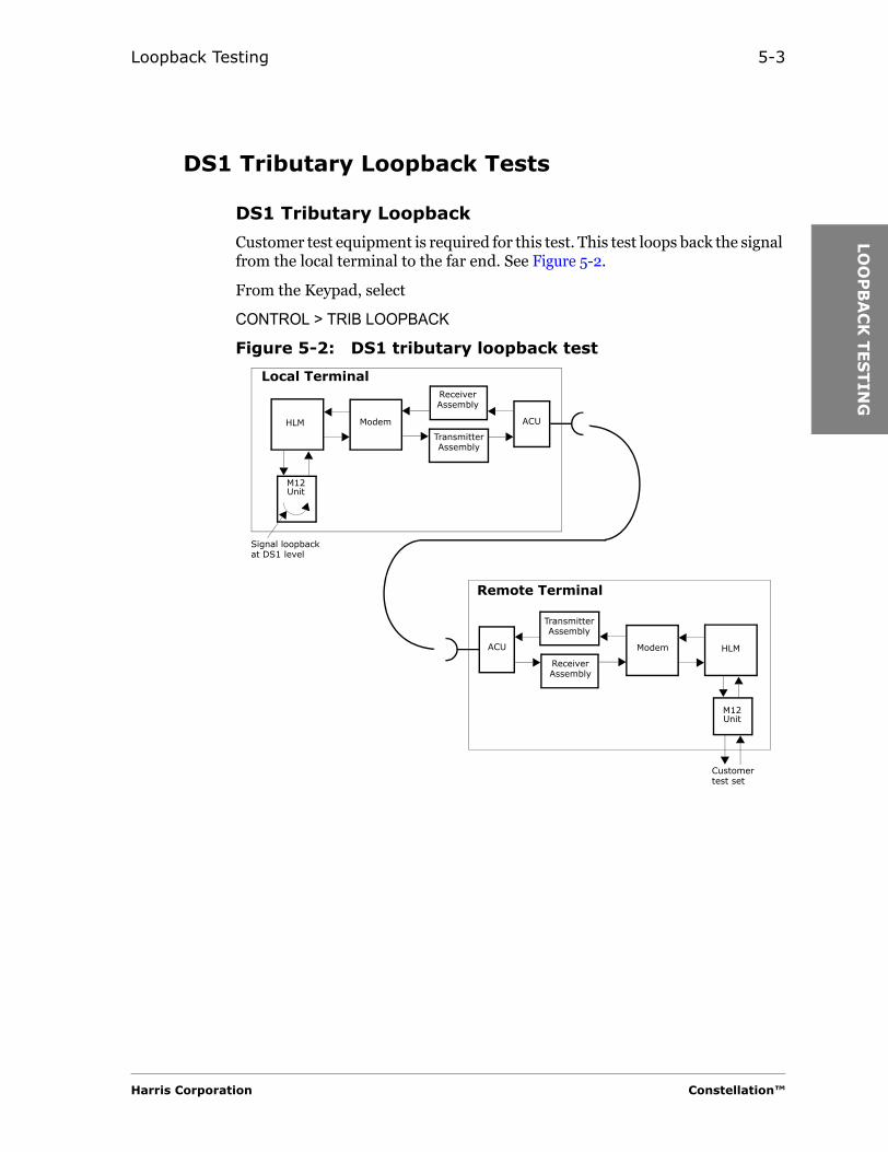
Loopback Testing 5-3
LOO
PB
AC
K T
ES
TIN
G
DS1 Tributary Loopback Tests
DS1 Tributary Loopback
Customer test equipment is required for this test. This test loops back the signal from the local terminal to the far end. See Figure 5-2.
From the Keypad, select
CONTROL > TRIB LOOPBACK
Figure 5-2: DS1 tributary loopback test
Transmitter Assembly
HLM Modem ACU
Receiver Assembly
Transmitter Assembly
HLMModemACU
Receiver Assembly
Local Terminal
Remote Terminal
Customer test set
Signal loopback at DS1 level
M12 Unit
M12 Unit
Harris Corporation Constellation™
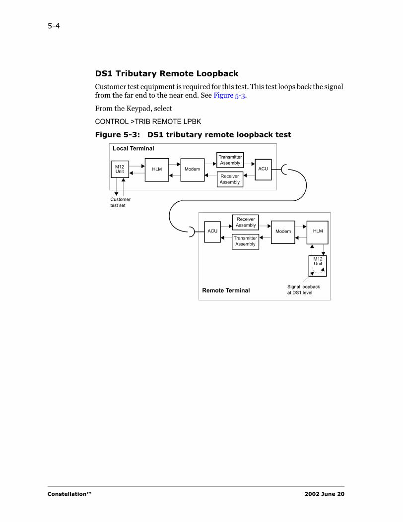
5-4
DS1 Tributary Remote Loopback
Customer test equipment is required for this test. This test loops back the signal from the far end to the near end. See Figure 5-3.
From the Keypad, select
CONTROL >TRIB REMOTE LPBK
Figure 5-3: DS1 tributary remote loopback test
Transmitter Assembly
HLM Modem ACUReceiver Assembly
Transmitter Assembly
HLMModemACU
Receiver Assembly
Local Terminal
Remote Terminal Signal loopback at DS1 level
M12 Unit
Customer test set
M12 Unit
Constellation™ 2002 June 20

Loopback Testing 5-5
LOO
PB
AC
K T
ES
TIN
G
OC3 Loopback Tests
OC3 Loopback
Customer test equipment is required for this test. This test loops back the signal from the local terminal to the far end. See Figure 5-4.
You need to access the hidden Control submenu to conduct the OC3 loopback test.
From the Keypad, select
CONTROL > hidden menu (F1 + F3 or Ctrl B) > OC3 LPBK
Figure 5-4: OC3 loopback test
HLM-155Hi Cap Modem ACU
Transmitter Assembly
HLM-155ACU
Receiver Assembly
Local Terminal
Remote Terminal
Customer test set
Hi Cap Modem
Wayside
Wayside
Transmitter Assembly
Receiver AssemblySTM1/
STS3orOC3
STM1/STS3orOC3
Harris Corporation Constellation™
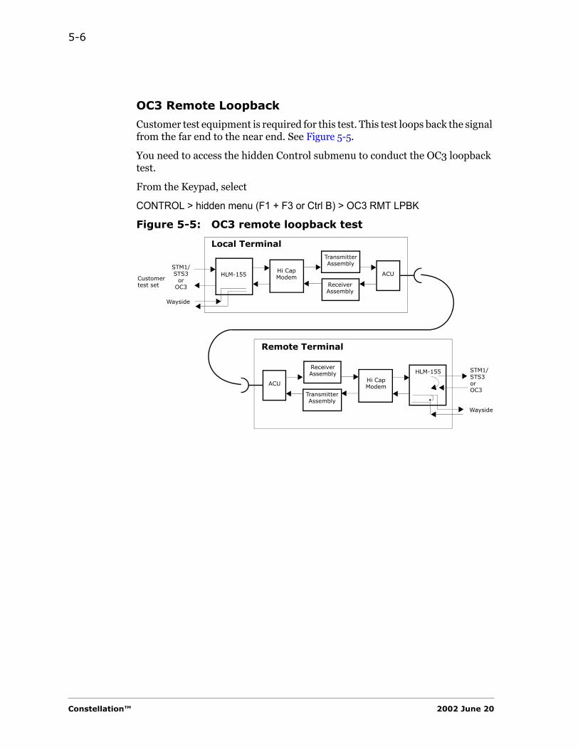
5-6
OC3 Remote Loopback
Customer test equipment is required for this test. This test loops back the signal from the far end to the near end. See Figure 5-5.
You need to access the hidden Control submenu to conduct the OC3 loopback test.
From the Keypad, select
CONTROL > hidden menu (F1 + F3 or Ctrl B) > OC3 RMT LPBK
Figure 5-5: OC3 remote loopback test
Transmitter Assembly
HLM-155Hi Cap Modem ACU
Receiver Assembly
ACU
Local Terminal
Remote Terminal
Customer test set
Hi Cap Modem
HLM-155
Wayside
Transmitter Assembly
Receiver Assembly
Wayside
STM1/STS3
orOC3
STM1/STS3orOC3
Constellation™ 2002 June 20
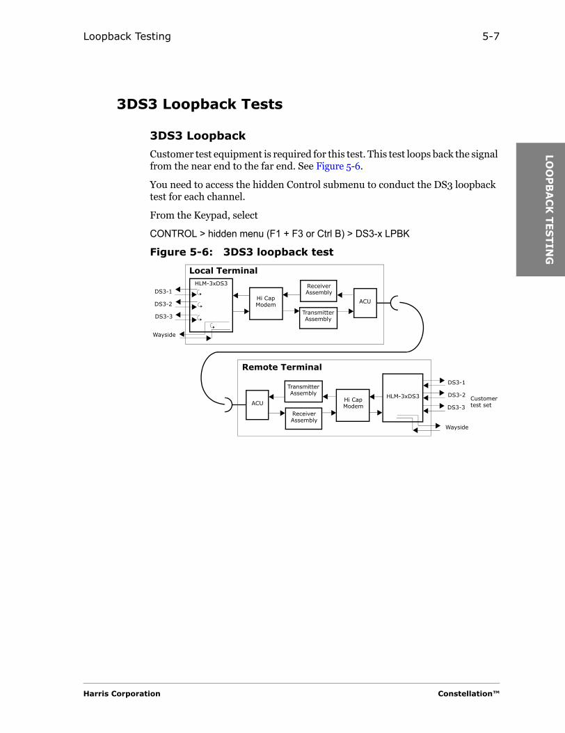
Loopback Testing 5-7
LOO
PB
AC
K T
ES
TIN
G
3DS3 Loopback Tests
3DS3 Loopback
Customer test equipment is required for this test. This test loops back the signal from the near end to the far end. See Figure 5-6.
You need to access the hidden Control submenu to conduct the DS3 loopback test for each channel.
From the Keypad, select
CONTROL > hidden menu (F1 + F3 or Ctrl B) > DS3-x LPBK
Figure 5-6: 3DS3 loopback test
HLM-3xDS3
Hi Cap Modem ACU
Transmitter Assembly
ACU
Receiver Assembly
Local Terminal
Remote Terminal
Customer test set
DS3-1
Hi Cap Modem
Wayside
Wayside
Transmitter Assembly
Receiver Assembly
HLM-3xDS3
DS3-2
DS3-3
DS3-1
DS3-2
DS3-3
Harris Corporation Constellation™
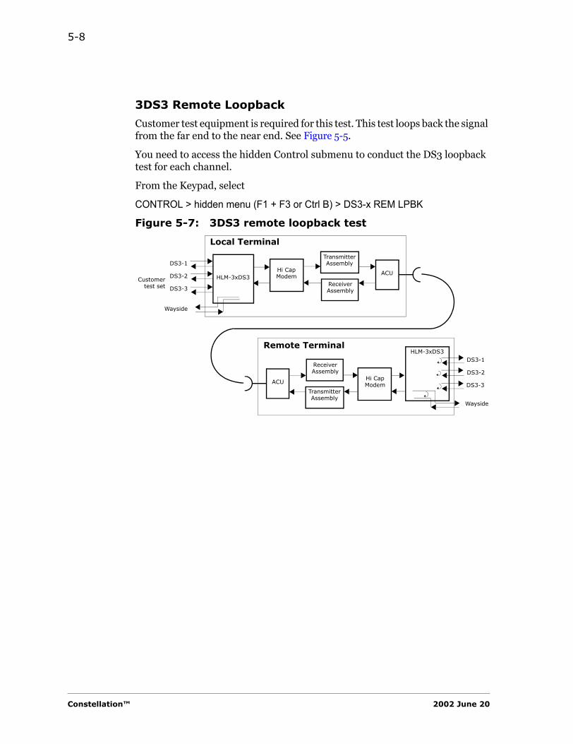
5-8
3DS3 Remote Loopback
Customer test equipment is required for this test. This test loops back the signal from the far end to the near end. See Figure 5-5.
You need to access the hidden Control submenu to conduct the DS3 loopback test for each channel.
From the Keypad, select
CONTROL > hidden menu (F1 + F3 or Ctrl B) > DS3-x REM LPBK
Figure 5-7: 3DS3 remote loopback test
Hi Cap Modem ACU
Transmitter Assembly
ACU
Receiver Assembly
Local Terminal
Remote Terminal
Hi Cap Modem
Transmitter Assembly
Receiver Assembly
HLM-3xDS3DS3-1
Wayside
DS3-2
DS3-3
Customertest set
Wayside
HLM-3xDS3
DS3-1
DS3-2
DS3-3
Constellation™ 2002 June 20
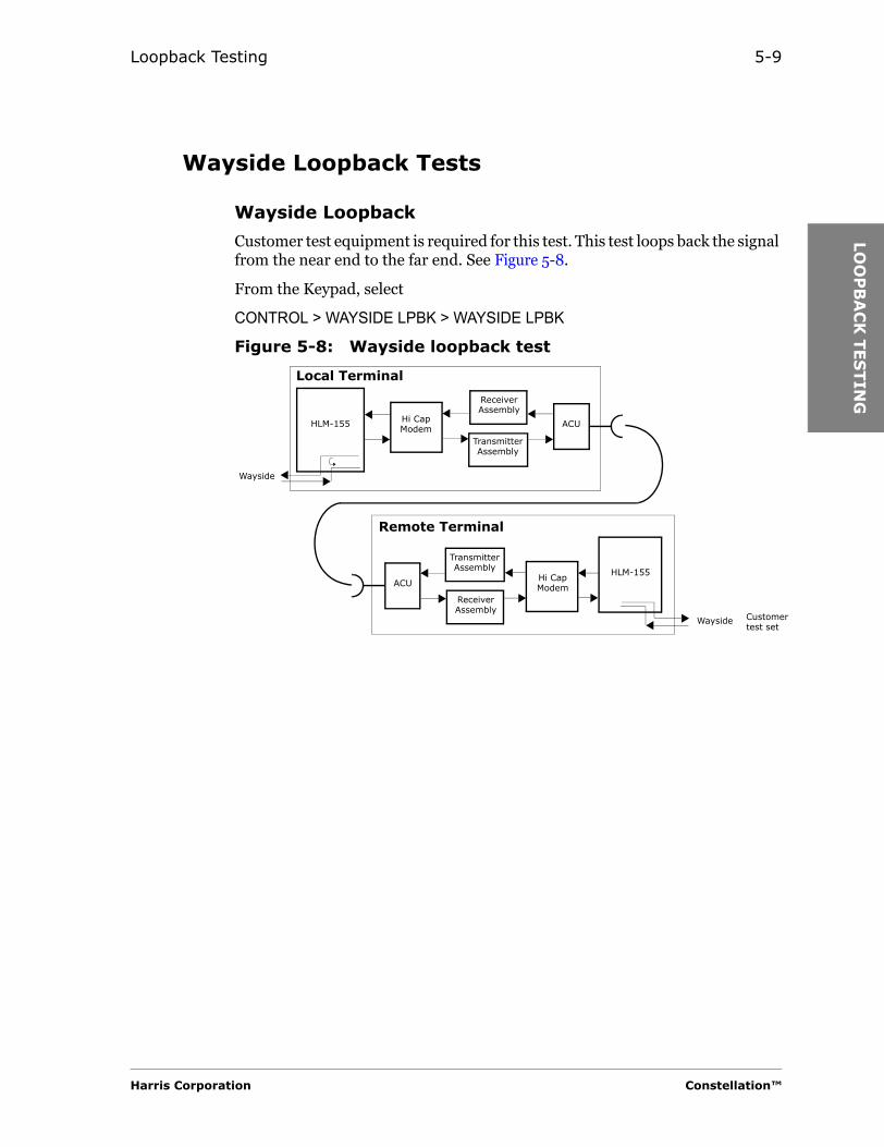
Loopback Testing 5-9
LOO
PB
AC
K T
ES
TIN
G
Wayside Loopback Tests
Wayside Loopback
Customer test equipment is required for this test. This test loops back the signal from the near end to the far end. See Figure 5-8.
From the Keypad, select
CONTROL > WAYSIDE LPBK > WAYSIDE LPBK
Figure 5-8: Wayside loopback test
HLM-155 Hi Cap Modem ACU
Transmitter Assembly
ACU
Receiver Assembly
Local Terminal
Remote Terminal
Customer test set
Hi Cap Modem
Wayside
Wayside
Transmitter Assembly
Receiver Assembly
HLM-155
Harris Corporation Constellation™

5-10
3DS3 Remote Loopback
Customer test equipment is required for this test. This test loops back the signal from the far end to the near end. See Figure 5-9.
From the Keypad, select
CONTROL > WAYSIDE LPBK > WAYSIDE RMT LPBK
Figure 5-9: Wayside remote loopback test
Hi Cap Modem ACU
Transmitter Assembly
ACU
Receiver Assembly
Local Terminal
Remote Terminal
Hi Cap Modem
Transmitter Assembly
Receiver Assembly
HLM-155
Wayside
Customertest set Wayside
HLM-155
Constellation™ 2002 June 20
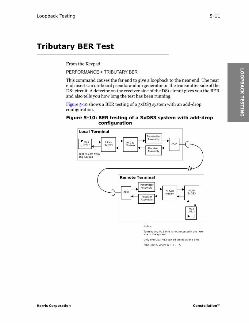
Loopback Testing 5-11
LOO
PB
AC
K T
ES
TIN
G
Tributary BER Test
From the Keypad
PERFORMANCE > TRIBUTARY BER
This command causes the far end to give a loopback to the near end. The near end inserts an on-board pseudorandom generator on the transmitter side of the DS1 circuit. A detector on the receiver side of the DS1 circuit gives you the BER and also tells you how long the test has been running.
Figure 5-10 shows a BER testing of a 3xDS3 system with an add-drop configuration.
Figure 5-10: BER testing of a 3xDS3 system with add-drop configuration
Transmitter Assembly
HLM-3xDS3
Hi Cap Modem
ACU
Receiver Assembly
BER results from the Keypad
Transmitter Assembly
HLM-3xDS3
Hi Cap Modem
ACU
Receiver Assembly
Local Terminal
Remote Terminal
M12 Unit n
M12 Unit n
Notes:
Terminating M12 Unit is not necessarily the next site in the system.
Only one DS1/M12 can be tested at one time.
M12 Unit n, where n = 1 ... 7.
Harris Corporation Constellation™

5-12
HLM-155 Electrical Interface
For HLM-155, Model 1, electrical interface, an input signal is required at the far end for the loopback function to operate.
Constellation™ 2002 June 20

CO
NFIG
UR
ING
TH
E
CO
NS
TELLA
TIO
N
RA
DIO
C H A P T E R
6CONFIGURING THE
CONSTELLATION RADIO
Refer to the Quick Reference Card or Appendix B for Keypad information.
SYSTEM from the CONFIGURATION Submenu
3DS3 CAPACITY USE (Constellation 155)
For a Constellation Radio with an HLM-3xDS3 unit, there are three channel configurations from which to select. Select DS3 only, select any DS3 channel to drop to 28 T1, or select any DS3 channel for a partial add-drop (4 T1, 8 T1, 12 T1, or 16 T1).
Harris Corporation Constellation™

6-2
Figure 6-1: DS3 only
Table 6-1: 3DS3 CAPACITY USE
SYSTEM Submenu
Selection Explanation
3DS3 CAPACITY USE
T3-1, T3-2, T3-3 All three channels use T3 signals (Figure 6-1).
T2 ADM, T3-2, T3-3
DS3 channel 1 to add-drop T1 signals.Use the ADM submenu to select the M12 Unit(s).
T3-1, T2 ADM, T3-3
DS3 channel 2 to add-drop T1 signals.Use the ADM submenu to select the M12 Unit(s).
T3-1, T3-2, T2 ADM
DS3 channel 3 to add-drop T1 signals (Figure 6-2).Use the ADM submenu to select the M12 Unit(s).
28 T1, T3-2, T3-3
DS3 channel 1 to terminate to 28 T1
T3-1, 28 T1, T3-3
DS3 channel 2 to terminate to 28 T1.
T3-1, T3-2, 28 T1
DS3 channel 3 to terminate to 28 T1 (Figure 6-3).
DS3-1
DS3-2
DS3-3
RFshelf
HLM
ModemACU
DS1 (Wayside)
Constellation™ 2002 June 20
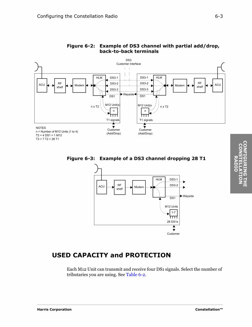
Configuring the Constellation Radio 6-3
CO
NFIG
UR
ING
TH
E
CO
NS
TELLA
TIO
N
RA
DIO
Figure 6-2: Example of DS3 channel with partial add/drop, back-to-back terminals
Figure 6-3: Example of a DS3 channel dropping 28 T1
USED CAPACITY and PROTECTION
Each M12 Unit can transmit and receive four DS1 signals. Select the number of tributaries you are using. See Table 6-2.
n
DS3-1
DS3-2
DS3-3
RFshelf
HLM
Modem ACURFshelf
HLM
ModemACU
T1 signals
n x T2
Customer(Add/Drop)
n
M12 Unit(s)
T1 signals
n x T2
Customer(Add/Drop)
DS3-1
DS3-2
DS3-3
DS3Customer interface
NOTESn = Number of M12 Units (1 to 4)T2 = 4 DS1 = 1 M12T3 = 7 T2 = 28 T1
M12 Unit(s)
WaysideDS1 DS1
1-7
DS3-1
DS3-2RFshelf
HLM
ModemACU
28 DS1s
Customer
M12 Units
WaysideDS1
Harris Corporation Constellation™
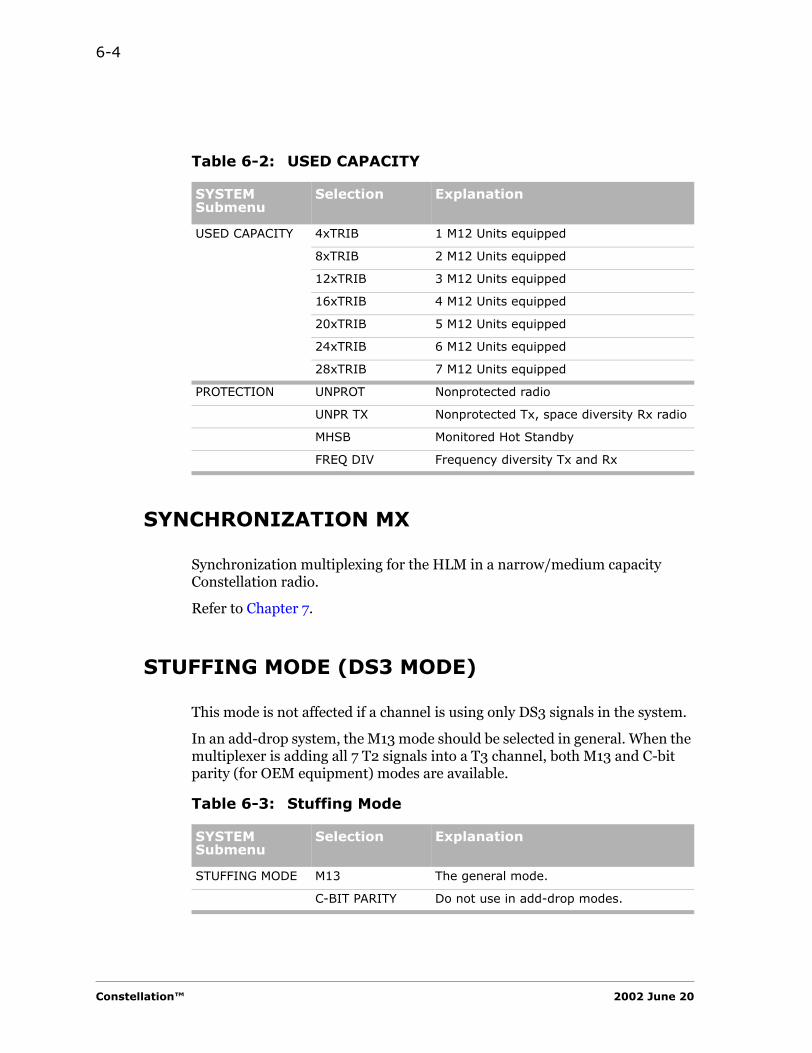
6-4
SYNCHRONIZATION MX
Synchronization multiplexing for the HLM in a narrow/medium capacity Constellation radio.
Refer to Chapter 7.
STUFFING MODE (DS3 MODE)
This mode is not affected if a channel is using only DS3 signals in the system.
In an add-drop system, the M13 mode should be selected in general. When the multiplexer is adding all 7 T2 signals into a T3 channel, both M13 and C-bit parity (for OEM equipment) modes are available.
Table 6-2: USED CAPACITY
SYSTEM Submenu
Selection Explanation
USED CAPACITY 4xTRIB 1 M12 Units equipped
8xTRIB 2 M12 Units equipped
12xTRIB 3 M12 Units equipped
16xTRIB 4 M12 Units equipped
20xTRIB 5 M12 Units equipped
24xTRIB 6 M12 Units equipped
28xTRIB 7 M12 Units equipped
PROTECTION UNPROT Nonprotected radio
UNPR TX Nonprotected Tx, space diversity Rx radio
MHSB Monitored Hot Standby
FREQ DIV Frequency diversity Tx and Rx
Table 6-3: Stuffing Mode
SYSTEM Submenu
Selection Explanation
STUFFING MODE M13 The general mode.
C-BIT PARITY Do not use in add-drop modes.
Constellation™ 2002 June 20

Configuring the Constellation Radio 6-5
CO
NFIG
UR
ING
TH
E
CO
NS
TELLA
TIO
N
RA
DIO
ATPC, M12 PROTECTION, SVC, FAN, PATH ALARMS MENU, AND CONFIG ALARM
Table 6-4: ATPC, M12 PROTECTION, SVC, FAN, PATH ALARMS MENU, AND CONFIG ALARM
SYSTEM Submenu
Selection Explanation
TX ATPC DISABLE HIGH Disable ATPC; set Tx at High power.
DISABLE LOW Disable ATPC; set Tx at Low power.
ENABLE Enable ATPC.
M12 PROTECTION NON REV Nonrevertive.When this option is selected, an automatic switching from the standby M12 Unit to the working unit does not occur whenever a failed unit is replaced by a working one.
REVERTIVE When this option is selected, an automatic switching from the standby M12 Unit to the working unit occurs whenever a failed unit is replaced by a working one.
SVC OPTION INSTALL Choose this command to put the Service Channel into service.
UNINSTALL Choose this command to put the Service Channel out of service.
FAN OPTION INSTALL Choose this command for new installation of the radio.
UNINSTAL Choose this command to put the Fan out of service.
PATH A, B ALARMS MENU
SHOW Displays the A and B alarms menu
HIDE If you choose HIDE, the RSL LOW and SIGNAL DEGRADED alarms will not be displayed.
CONFIG ALARM CLR/SET This item does not display for new installation.This alarm displays only if there is a configuration alarm.
Harris Corporation Constellation™
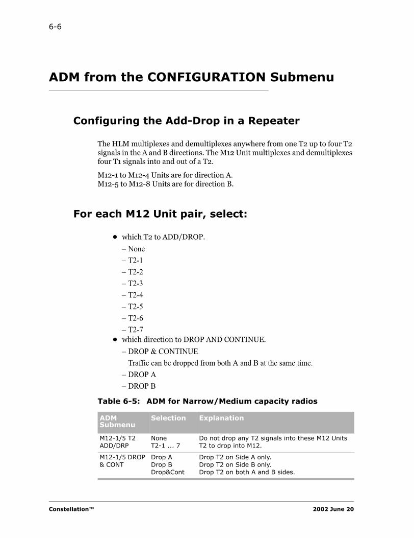
6-6
ADM from the CONFIGURATION Submenu
Configuring the Add-Drop in a Repeater
The HLM multiplexes and demultiplexes anywhere from one T2 up to four T2 signals in the A and B directions. The M12 Unit multiplexes and demultiplexes four T1 signals into and out of a T2.
M12-1 to M12-4 Units are for direction A.M12-5 to M12-8 Units are for direction B.
For each M12 Unit pair, select:
• which T2 to ADD/DROP.
– None– T2-1– T2-2– T2-3– T2-4– T2-5– T2-6– T2-7
• which direction to DROP AND CONTINUE.
– DROP & CONTINUETraffic can be dropped from both A and B at the same time.
– DROP A– DROP B
Table 6-5: ADM for Narrow/Medium capacity radios
ADM Submenu
Selection Explanation
M12-1/5 T2 ADD/DRP
NoneT2-1 ... 7
Do not drop any T2 signals into these M12 UnitsT2 to drop into M12.
M12-1/5 DROP & CONT
Drop ADrop BDrop&Cont
Drop T2 on Side A only.Drop T2 on Side B only.Drop T2 on both A and B sides.
Constellation™ 2002 June 20
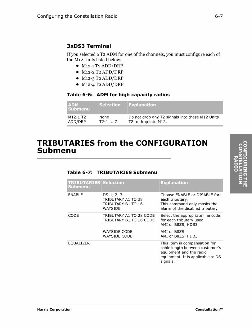
Configuring the Constellation Radio 6-7
CO
NFIG
UR
ING
TH
E
CO
NS
TELLA
TIO
N
RA
DIO
3xDS3 Terminal
If you selected a T2 ADM for one of the channels, you must configure each of the M12 Units listed below.
• M12-1 T2 ADD/DRP• M12-2 T2 ADD/DRP• M12-3 T2 ADD/DRP• M12-4 T2 ADD/DRP
TRIBUTARIES from the CONFIGURATION Submenu
Table 6-6: ADM for high capacity radios
ADM Submenu
Selection Explanation
M12-1 T2 ADD/DRP
NoneT2-1 ... 7
Do not drop any T2 signals into these M12 UnitsT2 to drop into M12.
Table 6-7: TRIBUTARIES Submenu
TRIBUTARIES Submenu
Selection Explanation
ENABLE DS-1, 2, 3TRIBUTARY A1 TO 28TRIBUTARY B1 TO 16WAYSIDE
Choose ENABLE or DISABLE for each tributary.This command only masks the alarm of the disabled tributary.
CODE TRIBUTARY A1 TO 28 CODETRIBUTARY B1 TO 16 CODE
Select the appropriate line code for each tributary used.AMI or B8ZS, HDB3
WAYSIDE CODEWAYSIDE CODE
AMI or B8ZSAMI or B8ZS, HDB3
EQUALIZER This item is compensation for cable length between customer’s equipment and the radio equipment. It is applicable to DS signals.
Harris Corporation Constellation™
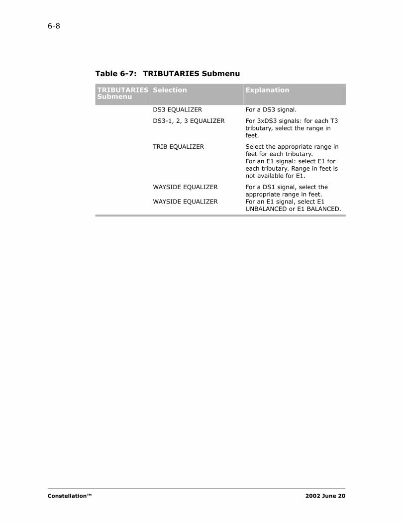
6-8
DS3 EQUALIZER For a DS3 signal.
DS3-1, 2, 3 EQUALIZER For 3xDS3 signals: for each T3 tributary, select the range in feet.
TRIB EQUALIZER Select the appropriate range in feet for each tributary.For an E1 signal: select E1 for each tributary. Range in feet is not available for E1.
WAYSIDE EQUALIZER
WAYSIDE EQUALIZER
For a DS1 signal, select the appropriate range in feet.For an E1 signal, select E1 UNBALANCED or E1 BALANCED.
Table 6-7: TRIBUTARIES Submenu
TRIBUTARIES Submenu
Selection Explanation
Constellation™ 2002 June 20

Configuring the Constellation Radio 6-9
CO
NFIG
UR
ING
TH
E
CO
NS
TELLA
TIO
N
RA
DIO
RELAYS from the CONFIGURATION Submenu
• There are a list of
– 8 relay outputs– 17 alarm configurations
• Defaults
– For RELAY 1, MAJOR ALARM is the default.– For RELAY 2, MINOR ALARM is the default.
Table 6-8: RELAYS Submenu
RELAYS Submenu
Selection Explanation
RELAY 1 TO RELAY 8 INPUT
Manual Control (external site control)Major AlarmMinor AlarmInput LOSSync Loss ASync Loss BErrored Seconds AErrored Seconds BSignal Degradation A1Signal Degradation A2Signal Degradation B1Signal Degradation B2On Line Mod/Tx AOn Line Mod/Tx BOn Line Rx AOn Line Rx BOn Line HLM
Select the alarm defined for the Relay number.
Harris Corporation Constellation™

6-10
Configuring the SERVICE CHANNEL
CONFIGURATION Submenu
Table 6-9: SERVICE CHANNEL submenu
SERVICE CHANNEL Submenu
Selection Explanation
ADDRESS 000-999 Must be three digits.This is a unique address for the Service Channel.
MODE LINEAR For a linear system.
The system automatically selects Terminal or Repeater mode.
LPMASTER or LP SLAVE
For a loop system:Select either LP MASTER or LP SLAVE. Only one MASTER per loop can be selected, but there must be one
VF PORT 1 LEVEL(to set the required VF level)
0 dBm7 dBm-16 dBm
For both transmit and receive directions.For receive direction.For transmit direction.
VF PORT 2 LEVEL(to set the required VF level)
-16 dBm7 dBm0 dBm
For receive direction.For transmit direction.For both transmit and receive directions.
DATA BRIDGE ISOLATE
BRIDGE
Provides full duplex in a port-to-port application.Provides half-duplex communication.
Constellation™ 2002 June 20
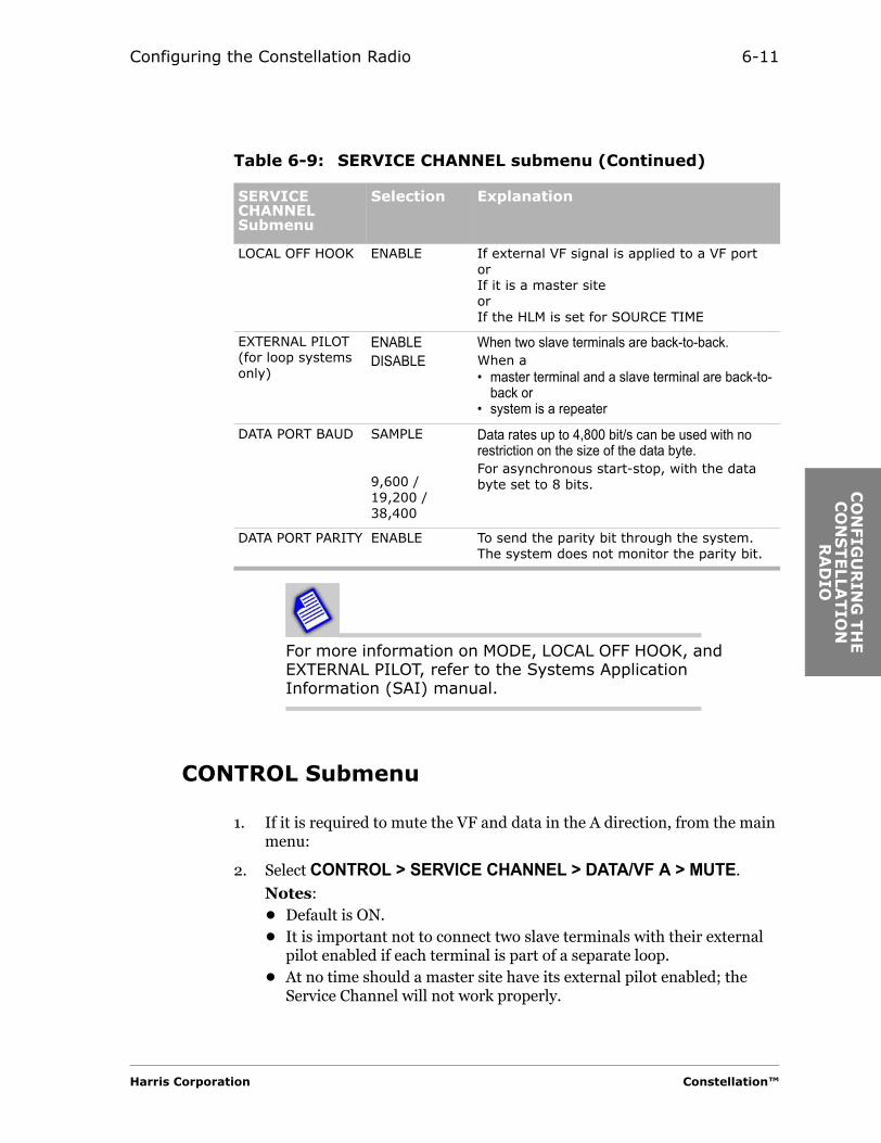
Configuring the Constellation Radio 6-11
CO
NFIG
UR
ING
TH
E
CO
NS
TELLA
TIO
N
RA
DIO
For more information on MODE, LOCAL OFF HOOK, and EXTERNAL PILOT, refer to the Systems Application Information (SAI) manual.
CONTROL Submenu
1. If it is required to mute the VF and data in the A direction, from the main menu:
2. Select CONTROL > SERVICE CHANNEL > DATA/VF A > MUTE.
Notes: • Default is ON.• It is important not to connect two slave terminals with their external
pilot enabled if each terminal is part of a separate loop.• At no time should a master site have its external pilot enabled; the
Service Channel will not work properly.
LOCAL OFF HOOK ENABLE If external VF signal is applied to a VF portorIf it is a master siteorIf the HLM is set for SOURCE TIME
EXTERNAL PILOT(for loop systems only)
ENABLEDISABLE
When two slave terminals are back-to-back.When a• master terminal and a slave terminal are back-to-
back or• system is a repeater
DATA PORT BAUD SAMPLE
9,600 / 19,200 / 38,400
Data rates up to 4,800 bit/s can be used with no restriction on the size of the data byte.For asynchronous start-stop, with the data byte set to 8 bits.
DATA PORT PARITY ENABLE To send the parity bit through the system. The system does not monitor the parity bit.
Table 6-9: SERVICE CHANNEL submenu (Continued)
SERVICE CHANNEL Submenu
Selection Explanation
Harris Corporation Constellation™

6-12
NETWORK MANAGEMENT
For NEWORK MANGEMENT configuration, refer to Chapter 8.
Constellation™ 2002 June 20
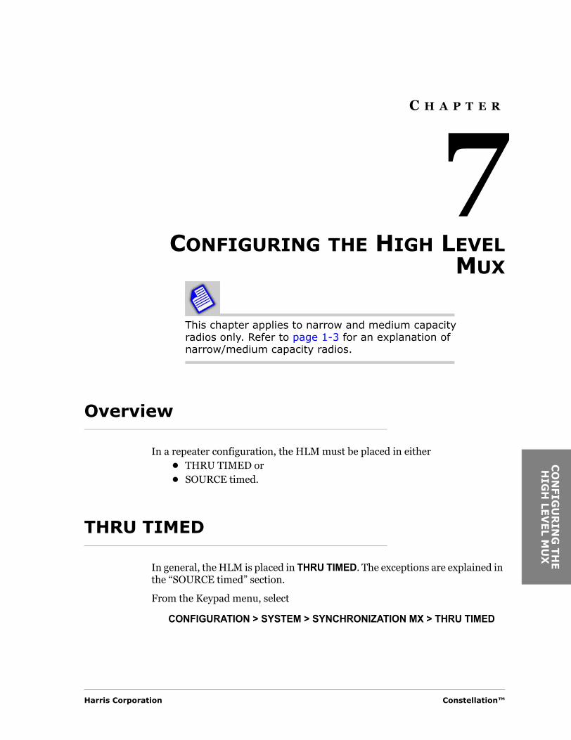
CO
NFIG
UR
ING
TH
E
HIG
H LE
VEL M
UX
C H A P T E R
7CONFIGURING THE HIGH LEVEL
MUX
This chapter applies to narrow and medium capacity radios only. Refer to page 1-3 for an explanation of narrow/medium capacity radios.
Overview
In a repeater configuration, the HLM must be placed in either • THRU TIMED or • SOURCE timed.
THRU TIMED
In general, the HLM is placed in THRU TIMED. The exceptions are explained in the “SOURCE timed” section.
From the Keypad menu, select
CONFIGURATION > SYSTEM > SYNCHRONIZATION MX > THRU TIMED
Harris Corporation Constellation™
7-2
SOURCE Timed
Source Timed Configurations
Select Source timed in the following cases.• In a repeater system where the Modem units are not the same (that is,
one is 115072 and the other is 115430), ensure that the system synchronization is set to SOURCE timed.
• In a loop system, when the HLM is at a master site, the HLM must be set to SOURCE timed.
• Terminal configuration.
From the Keypad menu, select
CONFIGURATION > SYSTEM > SYNCHRONIZATION MX > SOURCE
If the HLM is set for SOURCE timed, select enable local off hook for the Service Channel.
CONFIGURATION > SERVICE CHANNEL > LOCAL OFF HOOK > ENABLE
Constellation™ 2002 June 20

IP
CO
MM
UN
ICA
TS
TA
CK
AN
D
C H A P T E R
8IP COMMUNICATION STACK AND
IP APPLICATIONS
TCP/IP-to-Netcom Connectivity
Figure 8-1 shows one example of a TCP/IP-to-Netcom connectivity for the Constellation radio.
A Network Manager is to be connected to the Netcom Network by:• Direct–LAN
Net Manager 1 and Net Manager 2 may or may not be on the same subnet, and may or may not have connectivity to each other.
Harris Corporation Constellation™
ION
IP

8-2
Figure 8-1: Constellation TCP/IP-to-Netcom connectivity
Protocol Layers
To provide TCP/IP service within the Constellation Network, the TCP/IP suite requires a physical and a data link layer assistance. TCP/IP over Ethernet is configured with Ethernet in the data link layer and a twisted-pair cable in the physical layer.
In Harris’ TCP/IP over Netcom architecture, the microwave radio replaces the twisted-pair cable and Netcom replaces Ethernet.
Figure 8-2 is a comparison of the two protocol layer schemes.
Net Manager #1
Net Manager #2
EthernetNetwork
(Intra or Inter)
NetcomNode#110
NetcomNode#111
NetcomNode#112
NetcomNode#113
NetworkInterface(802.3)
NetcomNode#133
NetcomNode#130
NetcomNode#131
NetcomNode#132
NetcomNode#122
NetcomNode#121
NetcomNode#120
NetcomNode#123
Constellation NetworkC&M message delivery via Netcom
Note: Network Interface and Netcom are not the same subnet.
Constellation™ 2002 June 20

IP Communication Stack and IP Applications 8-3
IP
CO
MM
UN
ICA
TS
TA
CK
AN
D
Figure 8-2: Protocol layers
IP Routing
Standard IP routing is accomplished through the use of the IP routing table. See Figure 8-3.
Figure 8-3: IP routing
This scheme is true of IP routing using static routing tables and of IP routing using dynamic routing tables. Static routing requires operator assistance to build and maintain the routing tables. Dynamic routing requires the implementation of a routing protocol (that is, RIP) to query the network and to update the routing tables. Both dynamic routing and static routing can be used.
Constellation supports both RIP 1 and RIP 2 dynamic routing tables.
Application
Presentation
Session
Transport
Network
Data Link
Physical
TCP/IP over Ethernet TCP/IP over Netcom
Twisted Pair (etc)
Ethernet
I P
TCP
Microwave Radio
Netcom
I P, Netcom
TCP
IP Router
Application
Presentation
Session
Transport
Network
Data Link
Physical
IP Datagram
IP Datagram
IP Datagram
IP Datagram
IP RoutingSoftware
Routing Tables
Harris Corporation Constellation™
ION
IP
8-4
Community ID
Two communities are defined. These Community IDs are not user-configurable.
• “public”
Community with full access to the MIB objects (read-write)
• “private”
Community with read-only access to the MIB objects (read-only)
Network Management Submenu
CONFIGURATION Menu
Use the Configuration menu on the Keypad to gain access to the following Network Management submenu.
• NE ADDRESS• IP ROUTING
– AUX PORT CONFIG– NETCOM INTERFACE– ETHERNET INTERFACE– RIP
• NETCOM OVER ETHERNET• SNMP• COMM PORT SETTSINGS• REBOOT SYSTEM
Constellation™ 2002 June 20
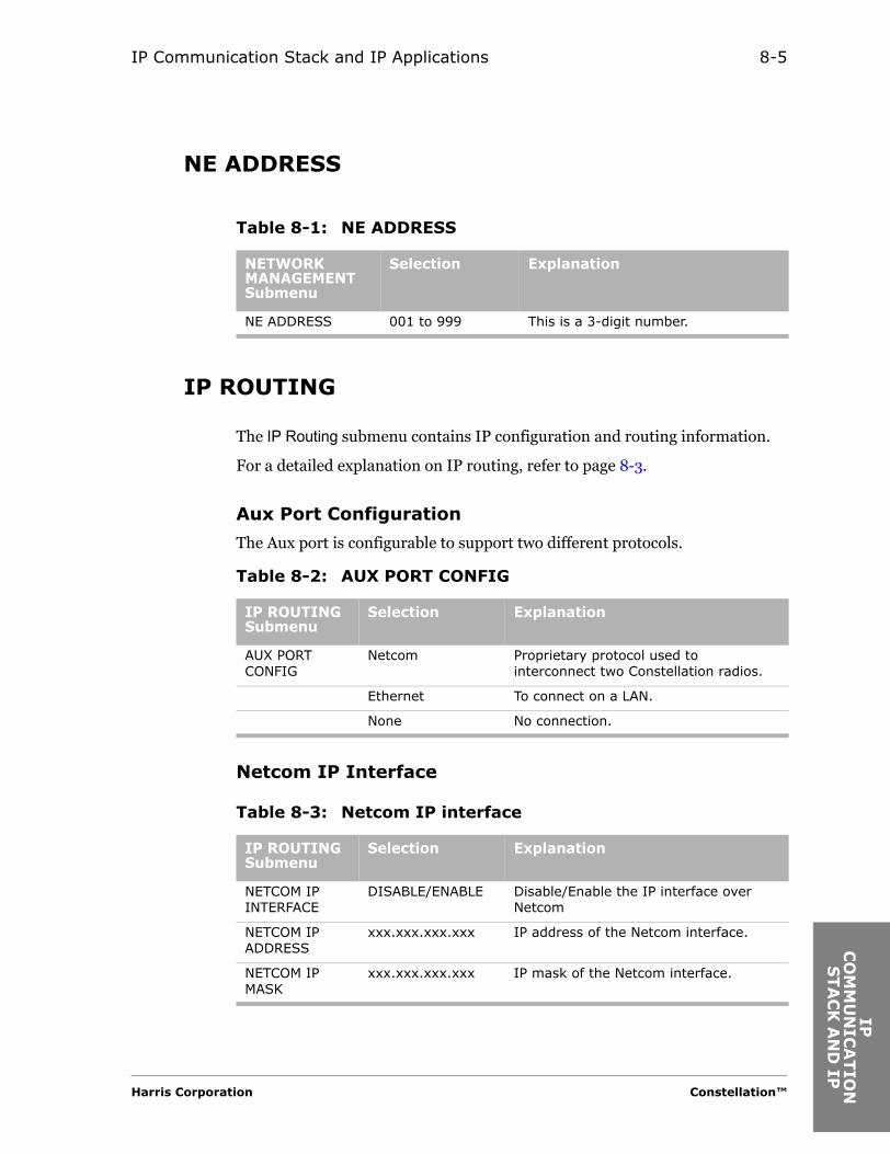
IP Communication Stack and IP Applications 8-5
IP
CO
MM
UN
ICA
TS
TA
CK
AN
D
NE ADDRESS
IP ROUTING
The IP Routing submenu contains IP configuration and routing information.
For a detailed explanation on IP routing, refer to page 8-3.
Aux Port Configuration
The Aux port is configurable to support two different protocols.
Netcom IP Interface
Table 8-1: NE ADDRESS
NETWORK MANAGEMENT Submenu
Selection Explanation
NE ADDRESS 001 to 999 This is a 3-digit number.
Table 8-2: AUX PORT CONFIG
IP ROUTING Submenu
Selection Explanation
AUX PORT CONFIG
Netcom Proprietary protocol used to interconnect two Constellation radios.
Ethernet To connect on a LAN.
None No connection.
Table 8-3: Netcom IP interface
IP ROUTING Submenu
Selection Explanation
NETCOM IP INTERFACE
DISABLE/ENABLE Disable/Enable the IP interface over Netcom
NETCOM IP ADDRESS
xxx.xxx.xxx.xxx IP address of the Netcom interface.
NETCOM IP MASK
xxx.xxx.xxx.xxx IP mask of the Netcom interface.
Harris Corporation Constellation™
ION
IP
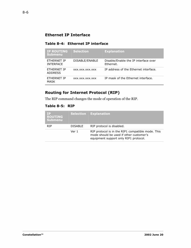
8-6
Ethernet IP Interface
Routing for Internet Protocol (RIP)
The RIP command changes the mode of operation of the RIP.
Table 8-4: Ethernet IP interface
IP ROUTING Submenu
Selection Explanation
ETHERNET IP INTERFACE
DISABLE/ENABLE Disable/Enable the IP interface over Ethernet.
ETHERNET IP ADDRESS
xxx.xxx.xxx.xxx IP address of the Ethernet interface.
ETHERNET IP MASK
xxx.xxx.xxx.xxx IP mask of the Ethernet interface.
Table 8-5: RIP
IP ROUTING Submenu
Selection Explanation
RIP DISABLE RIP protocol is disabled.
Ver 1 RIP protocol is in the RIP1 compatible mode. This mode should be used if other customer’s equipment support only RIP1 protocol.
Constellation™ 2002 June 20
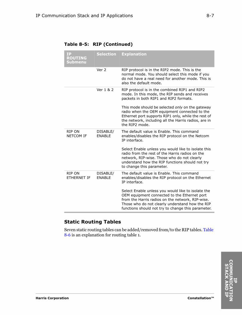
IP Communication Stack and IP Applications 8-7
IP
CO
MM
UN
ICA
TS
TA
CK
AN
D
Static Routing Tables
Seven static routing tables can be added/removed from/to the RIP tables. Table 8-6 is an explanation for routing table 1.
Ver 2 RIP protocol is in the RIP2 mode. This is the normal mode. You should select this mode if you do not have a real need for another mode. This is also the default mode.
Ver 1 & 2 RIP protocol is in the combined RIP1 and RIP2 mode. In this mode, the RIP sends and receives packets in both RIP1 and RIP2 formats.
This mode should be selected only on the gateway radio when the OEM equipment connected to the Ethernet port supports RIP1 only, while the rest of the network, including all the Harris radios, are in the RIP2 mode.
RIP ON NETCOM IF
DISABLE/ ENABLE
The default value is Enable. This command enables/disables the RIP protocol on the Netcom IP interface.
Select Enable unless you would like to isolate this radio from the rest of the Harris radios on the network, RIP-wise. Those who do not clearly understand how the RIP functions should not try to change this parameter.
RIP ON ETHERNET IF
DISABLE/ ENABLE
The default value is Enable. This command enables/disables the RIP protocol on the Ethernet IP interface.
Select Enable unless you would like to isolate the OEM equipment connected to the Ethernet port from the Harris radios on the network, RIP-wise. Those who do not clearly understand how the RIP functions should not try to change this parameter.
Table 8-5: RIP (Continued)
IP ROUTING Submenu
Selection Explanation
Harris Corporation Constellation™
ION
IP
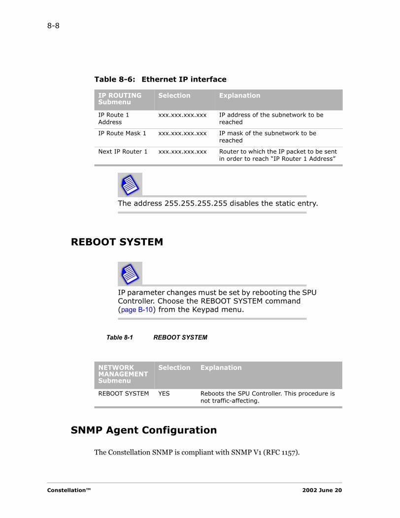
8-8
The address 255.255.255.255 disables the static entry.
REBOOT SYSTEM
IP parameter changes must be set by rebooting the SPU Controller. Choose the REBOOT SYSTEM command (page B-10) from the Keypad menu.
Table 8-1 REBOOT SYSTEM
SNMP Agent Configuration
The Constellation SNMP is compliant with SNMP V1 (RFC 1157).
Table 8-6: Ethernet IP interface
IP ROUTING Submenu
Selection Explanation
IP Route 1 Address
xxx.xxx.xxx.xxx IP address of the subnetwork to be reached
IP Route Mask 1 xxx.xxx.xxx.xxx IP mask of the subnetwork to be reached
Next IP Router 1 xxx.xxx.xxx.xxx Router to which the IP packet to be sent in order to reach “IP Router 1 Address”
NETWORK MANAGEMENT Submenu
Selection Explanation
REBOOT SYSTEM YES Reboots the SPU Controller. This procedure is not traffic-affecting.
Constellation™ 2002 June 20
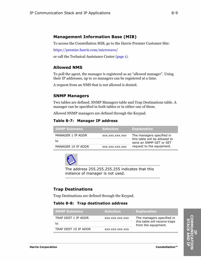
IP Communication Stack and IP Applications 8-9
IP
CO
MM
UN
ICA
TS
TA
CK
AN
D
Management Information Base (MIB)
To access the Constellation MIB, go to the Harris Premier Customer Site:
https://premier.harris.com/microwave/
or call the Technical Assistance Center (page 1).
Allowed NMS
To poll the agent, the manager is registered as an “allowed manager”. Using their IP addresses, up to 10 managers can be registered at a time.
A request from an NMS that is not allowed is denied.
SNMP Managers
Two tables are defined. SNMP Managers table and Trap Destinations table. A manager can be specified in both tables or in either one of them.
Allowed SNMP managers are defined through the Keypad.
The address 255.255.255.255 indicates that this instance of manager is not used.
Trap Destinations
Trap Destinations are defined through the Keypad.
Table 8-7: Manager IP address
SNMP Submenu Selection Explanation
MANAGER 1 IP ADDR xxx.xxx.xxx.xxx The managers specified in this table will be allowed to send an SNMP GET or SET request to the equipment.
to
MANAGER 10 IP ADDR xxx.xxx.xxx.xxx
Table 8-8: Trap destination address
SNMP Submenu Selection Explanation
TRAP DEST 1 IP ADDR xxx.xxx.xxx.xxx The managers specified in this table will receive traps from the equipment.to
TRAP DEST 10 IP ADDR xxx.xxx.xxx.xxx
Harris Corporation Constellation™
ION
IP
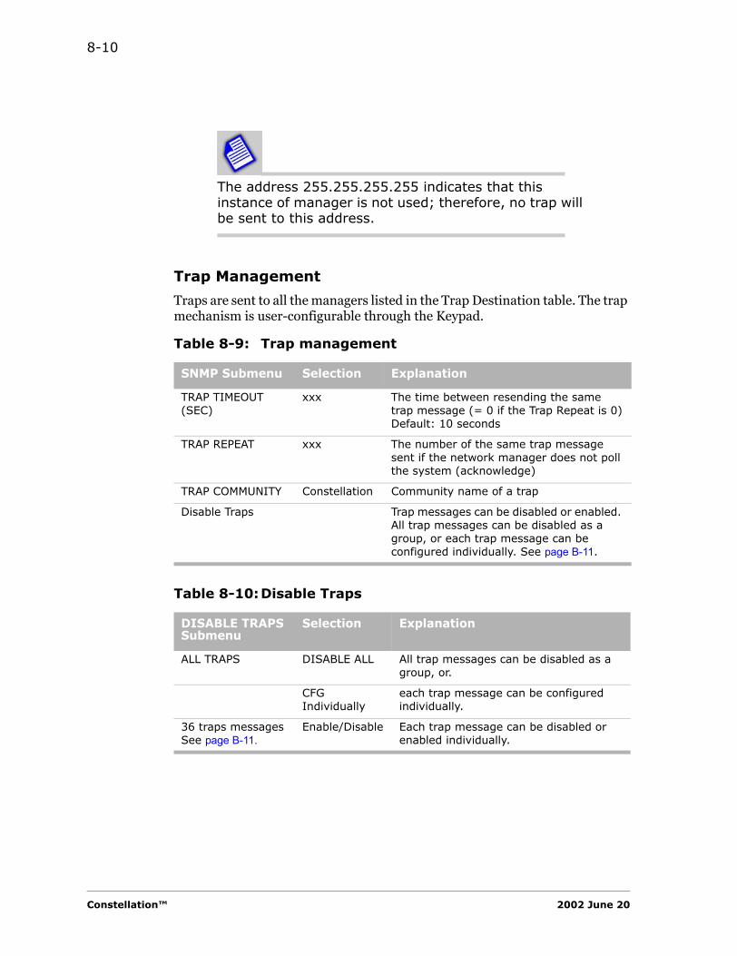
8-10
The address 255.255.255.255 indicates that this instance of manager is not used; therefore, no trap will be sent to this address.
Trap Management
Traps are sent to all the managers listed in the Trap Destination table. The trap mechanism is user-configurable through the Keypad.
Table 8-9: Trap management
SNMP Submenu Selection Explanation
TRAP TIMEOUT (SEC)
xxx The time between resending the same trap message (= 0 if the Trap Repeat is 0)Default: 10 seconds
TRAP REPEAT xxx The number of the same trap message sent if the network manager does not poll the system (acknowledge)
TRAP COMMUNITY Constellation Community name of a trap
Disable Traps Trap messages can be disabled or enabled. All trap messages can be disabled as a group, or each trap message can be configured individually. See page B-11.
Table 8-10:Disable Traps
DISABLE TRAPS Submenu
Selection Explanation
ALL TRAPS DISABLE ALL All trap messages can be disabled as a group, or.
CFG Individually
each trap message can be configured individually.
36 traps messages See page B-11.
Enable/Disable Each trap message can be disabled or enabled individually.
Constellation™ 2002 June 20
RO
UTIN
E
MA
INTEN
AN
CE
C H A P T E R9ROUTINE MAINTENANCE
Routine Observances
Routine observances of the Constellation Radio include the following:• Look at the LED indicators on the faceplates to ensure that they are
all green.
On protected systems, only the on-line units have the green LEDs lighted.
• Use the Keypad to do routine maintenance tests to ensure that the radio is performing properly.
FCC Requirements
The Federal Communications Commission (FCC) requires that records of transmitter measurements be maintained.
The following measurements should be taken at least once a year and recorded in a Maintenance Log (see Appendix F for an example of a Maintenance Log form).
• Transmitter Assembly
– Reference frequency– Power output (at the ACU transmit monitor port) (page 9-5)
Harris Corporation Constellation™

9-2
Monitoring Recommendations
It is important that you use high-quality adapters when monitoring power output at the radio monitor port. Inexpensive “screw together” adapters introduce unpredictable amounts of signal loss. Attempting to compensate for this signal loss can result in sync loss and errored seconds events.
Monitoring the Reference Frequency
Harris recommends monitoring the reference frequency during installation, and then at least once a year while the radio is in service.
The specification for the oscillator is +/- 300 Hz. The reference oscillator frequency can be adjusted through the Keypad. If it cannot be adjusted within 300 Hz, the OCXO should be replaced.
Performing routine checks and recording any adjustments can expose a potential crystal problem before there is a failure. Changes in crystal frequency are most likely in the first few months of operation. After three to six months, the crystal should stabilize.
UBER Measurement
UBER (uncorrected bit error ratio) is a measurement that shows BER before FEC takes place. UBER command can be accessed through the Keypad’s hidden Measurement submenu.
Constellation™ 2002 June 20
Routine Maintenance 9-3
RO
UTIN
E
MA
INTEN
AN
CE
General Measurements ProcedureTransmitter Frequency Measurement
The reason for performing these procedures is to ensure that the Transmitter Assembly is operating on the correct frequency and power level to comply with the license requirements. (Example: FCC Title 47, Part 101.107, 101.111, 101.113, and 101.217.) It also ensures that the residual BER floor and acquisition time remain within specification.
1. Record the operating frequency of the Transmitter from the Keypad (hidden menu).
CONFIGURATION > F1 + F3 or Ctrl B > TX FREQ
2. This frequency should match the one written on the Tx filter and the station authorization.
3. Determine from the table in Appendix C, which multiplier-filter should be used (or is in use).
The Transmitter Assembly should be plugged into the rack and powered for at least 30 minutes prior to adjusting the frequency. The position of the TX On/OFF switch does not affect the measurement. The power supply should be ON.
Harris Corporation Constellation™

9-4
The Frequency Counter should be plugged in and powered for at least 30 minutes prior to adjusting the frequency.
4. Connect a frequency counter to the REF MON port on the Transmitter Assembly (Figure 9-1).
5. To adjust the frequency, use the hidden Keypad command
CONFIGURATION > F1 + F3 or Ctrl B > TX 100MHZ TUNE
6. Adjust the frequency to
100.000,000 MHz ± (see table)
Year of Operation Tolerance
Initial adjustment ± 100 Hz
After one year of operation ± 200 Hz
Thereafter ± 300 Hz
Constellation™ 2002 June 20
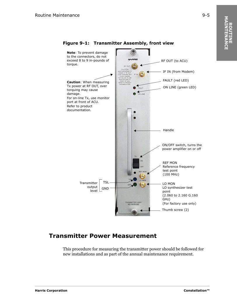
Routine Maintenance 9-5
RO
UTIN
E
MA
INTEN
AN
CE
Figure 9-1: Transmitter Assembly, front viewTransmitter Power Measurement
This procedure for measuring the transmitter power should be followed for new installations and as part of the annual maintenance requirement.
Note: To prevent damage to the connectors, do not exceed 8 to 9 in-pounds of torque.
IF IN (from Modem)
RF OUT (to ACU)
Thumb screw (2)
Transmitteroutput
level
LO MONLO synthesizer test point(2.060 to 2.160 G.160 GHz)(For factory use only)
REF MONReference frequencytest point(100 MHz)
ON/OFF switch, turns the power amplifier on or off
FAULT (red LED)
ON LINE (green LED)
TSL
GND
Handle
Caution: When measuring Tx power at RF OUT, over torquing may cause damage.For on-line Tx, use monitor port at front of ACU.Refer to product documentation.
Harris Corporation Constellation™

9-6
Note that this is a new procedure and should be followed from now on.
You may observe a low output alarm while you are performing calibration. Ignore the alarm until the calibration has been completed.
Measuring the Power Output of an Off-line Transmitter
If the Transmitter to be measured is off-line, then it must be placed on line.
The following procedure interrupts traffic.
7. Lock the Transmitter on line as follows:
From the Keypad main menu, select
CONTROL > LOCK/IF LPBK > LOCK MOD/TX > SET
Connecting the Power Meter
8. Connect the power head of the power meter to the transmit monitor port on the ACU. See Figure 9-2.
The monitor port is labeled “COUPLING LOSS FROM ANTENNA FLANGE CAL AT XMT FREQ __._”.
Constellation™ 2002 June 20

Routine Maintenance 9-7
RO
UTIN
E
MA
INTEN
AN
CE
Figure 9-2: Location of the transmit monitor portPower Meter Reading
9. The Power Meter reading should equal the value from Table 9-1 or Table 9-2 minus the Coupling Loss on the label.
Table 9-1: Power at antenna flange, NP configuration
TX Frequency(GHz)
8T 16T 28T/DS3 OC3/3xDS3
Power (dBm)
6 29.5 28.5 29.0 29.0
7/8 27.5 26.5 27.0 27.5
10/11 26.0 24.5 25.0 25.0
Table 9-2: Power at antenna flange, MHSB configuration
TX Frequency(GHz)
8T 16T 28T/DS3 OC3/3xDS3
Power (dBm)
6 29.1 28.1 28.6 28.6
7/8 27.1 26.1 26.6 27.1
10/11 25.6 24.1 24.6 24.6
Label:
COUPLING LOSS FROM ANTENNA FLANGE
CAL AT
XMT FREQ
Transmit monitor port
Harris Corporation Constellation™
9-8
The power at the top of the rack (TOR) = the power meter reading + the coupling loss shown on the monitor port label.
10. If the Power Meter reading does not equal the value calculated from step 9, use the Keypad to adjust the RF power out. Refer to the next section for a detailed procedure.
11. If power adjustment is required, go to step 12.If power adjustment is not required, go to step 22.
Keypad Procedure for Adjusting the RF Power Out
This procedure requires access to the hidden RF Configuration submenu.
12. Ensure that the Transmitter on line is locked.
From the Keypad main menu, select
CONTROL > LOCK/IF LPBK > LOCK MOD/TX > SET
13. For the high power calibration, access the hidden RF Configuration submenu from the Keypad main menu.
CONFIGURATION > F1 + F3 or Ctrl B > TX PWR CALIB > ADJUST HIGH PWR
14. Use the UP/DOWN keys until the value = the power meter reading + the coupling loss shown on the monitor port label.
15. Go to HIGH PWR CALIB, and enter the value from step 14.
Notes:
• Use the F2 key for the decimal point.
• You must enter 3 digits. For example, 30 dBm is entered as 30.0.
16. Exit.
17. Go to ADJUST LOW PWR.
18. Use the UP/DOWN keys until the value = the power meter reading + the coupling loss shown on the monitor port label.
Constellation™ 2002 June 20

Routine Maintenance 9-9
RO
UTIN
E
MA
INTEN
AN
CE
Tx Assy, Model 2: should be approximately 5 dB below high powerTx Assy, Model 3: should be approximately 10 dB below high power
Adjust if necessary.
19. Go to LOW PWR CALIB, and enter the value from step 18.
Notes:
• Use the F2 key for the decimal point.
• You must enter 3 digits. For example, 30 dBm is entered as 30.0.
20. Exit. It will automatically return to high power.
21. Unlock the on-line Transmitter.
From the Keypad main menu, select
CONTROL > LOCK/IF LPBK > LOCK MOD/TX > CLR
Recording the Power Levels
22. Record the power levels along with the date and the name of the person making the measurement in the “Routine Maintenance Log Form” (Appendix F).
Off-line Transmitter
23. When you have finished taking the measurement, you can either leave the Transmitter on line or return it to the off-line status.
24. The standby Transmitter is now the primary Transmitter.
Harris Corporation Constellation™
9-10
Switching the traffic back to the previous Transmitter will cause a hit.
If switching of Transmitter Assemblies is desired, it should be done during low-traffic hours.
Receiver Assembly Measurement
REF MON Frequency
The same procedure used in the “General Measurements Procedure” (page 9-3) may be used to measure the REF MON frequency.
Constellation™ 2002 June 20

Routine Maintenance 9-11
RO
UTIN
E
MA
INTEN
AN
CE
Figure 9-3: Receiver Assembly, front viewRSL Test Point. At nominally -26 dBm or higher, a 10 dB attenuator is engaged, resulting in a 1 volt drop (apparent 10 dB) in the RSL test point reading. The Keypad will display the corrected (unattenuated) value. At nominally -29 dBm, the attenuator is disengaged, and the meter will reflect the unattenuated value. See Figure 9-4.
Note: To prevent damage to the connectors, do not exceed 8 to 9 in-pounds of torque.
RF IN (from ACU)
IF OUT (to Modem)
Thumb screw
REF MON Reference frequency test point (100 MHz)
Test points foraligning the
antenna(See page 9-11)
FAULT(red LED)
ON LINE(green LED)
RSL
GND
Handle
LO MON*LO synthesizer test point(2.060 to 2.160 GHz)
(For factory use only)
Harris Corporation Constellation™

9-12
Figure 9-4: RSL measurement
If the signal level is too high for antenna alignment, the far-end Transmitter could be set to ATPC low power (about 10 dB lower than nominal high power setting). See Keypad menu, Appendix B.
CONFIGURATION > SYSTEM > TX ATPC > DISABLE LOW
If the signal level is still too high, a pad can be temporarily added at the Receiver input.
-26 dBm (-2.6 Vdc*)
-70 dBm(-7.0 Vdc)
-20 dBm (-3.0 Vdc)
-29 dBm(-3.9 Vdc***)
(-3.6 Vdc**)
(-2.9 Vdc#)
LEGEND( ) Test point reading.* Before the attenuator is engaged.** After the attenuator is engaged.*** Before the attenuator is disengaged.# After the attenuator is disengaged.
Constellation™ 2002 June 20
SY
STEM
SO
FTW
AR
E
UP
GR
AD
ES
C H A P T E R
10SYSTEM SOFTWARE UPGRADES
Obtaining New Software
New software is available from the Harris Premier Customer Site:
https://premier.harris.com/microwave/
or call the Technical Assistance Center (page 1).
Be sure to read the software release note before downloading the software into the Constellation radio.
Downloading New Software
Introduction
You will need the file with the latest Constellation System Software that contains the Download Utility v3.02 (Swdl.exe) or later.
There are two downloading procedures for equipment connected in a contiguous network. See Figure 10-1.
• Local Download
Harris Corporation Constellation™

10-2
Your PC is connected directly to the target radio you are downloading the system software to.
• Remote Download
Your PC is connected to any other Constellation radio on the network (gateway unit) and that the gateway unit can communicate with the target unit.
Figure 10-1: Local and remote download connections
Requirements
• IBM PC-compatible desktop or laptop computer• Windows 95, 98, ME NT or 2000 operating system with adequate
resources• Null cable for connecting the PC to the Constellation radio
– DE-9 to DE-9 cable (crossover cable)– DE-9 to RJ-45 cable
See Appendix A for pinout specifications.
Sliding window: (2 x n + 1) = 3 n = 1
Sliding window: (2 x n + 1) = 5 n = 2
Sliding window: (2 x n + 1) = 7 n = 3
Sliding window: (2 x n + 1) = 9 n = 4
Constellation™ 2002 June 20
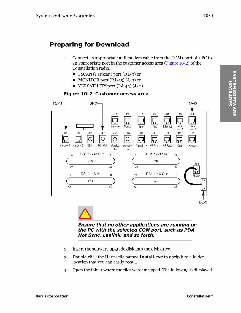
System Software Upgrades 10-3
SY
STEM
SO
FTW
AR
E
UP
GR
AD
ES
Preparing for Download
1. Connect an appropriate null modem cable from the COM1 port of a PC to an appropriate port in the customer access area (Figure 10-2) of the Constellation radio.• FSCAN (FarScan) port (DE-9) or• MONITOR port (RJ-45) (J33) or• VERSATILITY port (RJ-45) (J20).
Figure 10-2: Customer access area
Ensure that no other applications are running on the PC with the selected COM port, such as PDA Hot Sync, Laplink, and so forth.
2. Insert the software upgrade disk into the disk drive.
3. Double-click the Harris file named Install.exe to unzip it to a folder location that you can easily recall.
4. Open the folder where the files were unzipped. The following is displayed.
Wayside Monitor
VersaT1lity VF Port 1 VF Port 2Wayside Out
WaysideIn
DataPort 2
DS3 OutDS3 InHandset 2Handset 1
Aux EthernetSpur
KeypadCan
Fan
DS1 17-32 Out
DS1 1-16 In
DS1 17-32 In
DS1 1-16 Out FSCAN
DE-9
RJ-45RJ-11
26
25
26
25
25
25
26
26
1 1
11
50
50 50
50
BNC
DataPort 1
J16 J33 J17 J18 J31 J23 J24
J36J25 J32 J35J26 J27 J20 J21 J22 J15 J19
J28J29
J30
P15
P14
Harris Corporation Constellation™
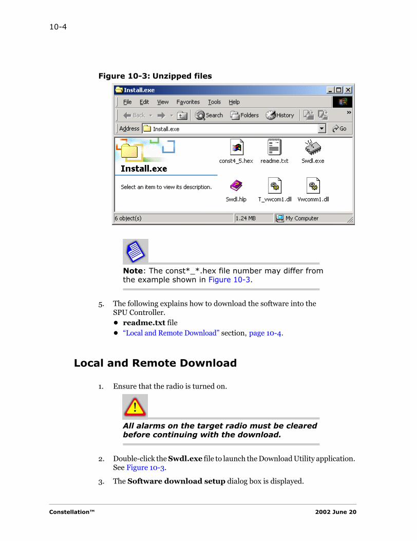
10-4
Figure 10-3: Unzipped files
Note: The const*_*.hex file number may differ from the example shown in Figure 10-3.
5. The following explains how to download the software into the SPU Controller.• readme.txt file • “Local and Remote Download” section, page 10-4.
Local and Remote Download
1. Ensure that the radio is turned on.
All alarms on the target radio must be cleared before continuing with the download.
2. Double-click the Swdl.exe file to launch the Download Utility application. See Figure 10-3.
3. The Software download setup dialog box is displayed.
Constellation™ 2002 June 20

System Software Upgrades 10-5
SY
STEM
SO
FTW
AR
E
UP
GR
AD
ES
Figure 10-4: Software download setup dialog box
a. Hex File
Use the Browse button to locate the Const*_*.hex (Const4_5.hex) file. This file is located in the folder where you unzipped the Install.exe file.
b. Download Setup, Sliding Window Size
The size depends on the position of the radio in the network. See Figure 10-1 for the formula.• Local Download: 3.• Remote Download: The size = 2 x n + 1, where n = links away from
the local site.
c. Connection
Master Address: The Master Address must be different from any FarScan/NE addresses present in the network you are downloading into.
Target Address: The target address is the FarScan or NE address of the radio where the software will be downloaded.
Harris Corporation Constellation™
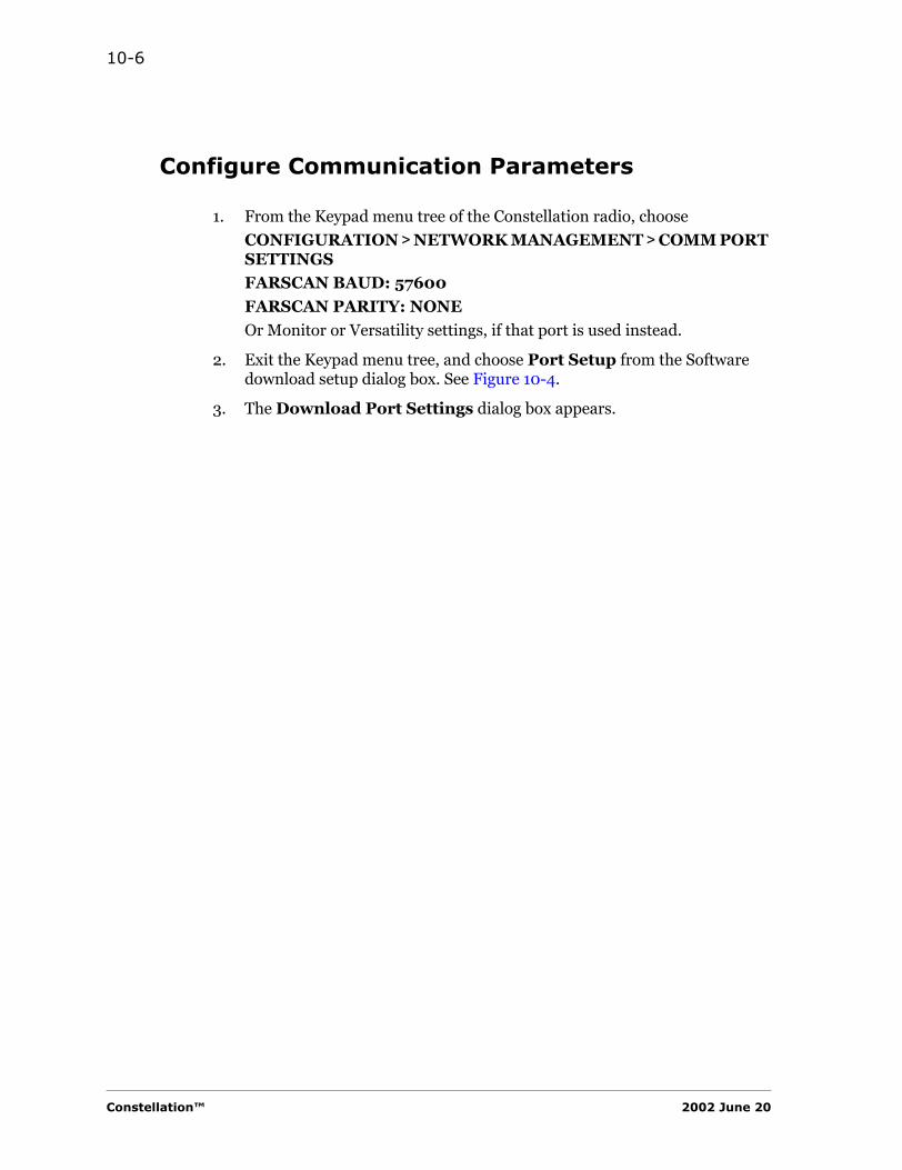
10-6
Configure Communication Parameters
1. From the Keypad menu tree of the Constellation radio, choose
CONFIGURATION > NETWORK MANAGEMENT > COMM PORT SETTINGS
FARSCAN BAUD: 57600
FARSCAN PARITY: NONE
Or Monitor or Versatility settings, if that port is used instead.
2. Exit the Keypad menu tree, and choose Port Setup from the Software download setup dialog box. See Figure 10-4.
3. The Download Port Settings dialog box appears.
Constellation™ 2002 June 20

System Software Upgrades 10-7
SY
STEM
SO
FTW
AR
E
UP
GR
AD
ES
Figure 10-5: Download Port Settings dialog box
d. In the COM Port Setup, choose:
Baud Rate: 57600
Parity: None
e. At the bottom of the Download Port Settings dialog box, clear the following three boxes.
Modem Connection
Check Hardware Connection
Modem Answer Mode
f. Click Ok.
Harris Corporation Constellation™
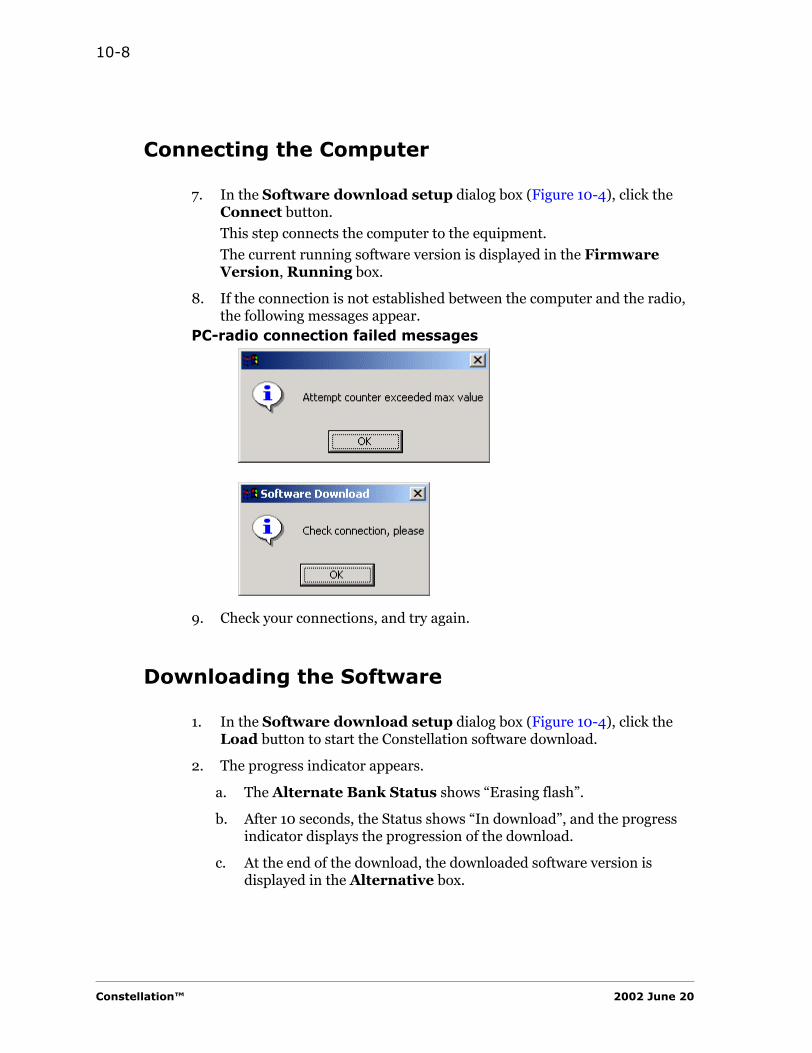
10-8
Connecting the Computer
7. In the Software download setup dialog box (Figure 10-4), click the Connect button.
This step connects the computer to the equipment.
The current running software version is displayed in the Firmware Version, Running box.
8. If the connection is not established between the computer and the radio, the following messages appear.
PC-radio connection failed messages
9. Check your connections, and try again.
Downloading the Software
1. In the Software download setup dialog box (Figure 10-4), click the Load button to start the Constellation software download.
2. The progress indicator appears.
a. The Alternate Bank Status shows “Erasing flash”.
b. After 10 seconds, the Status shows “In download”, and the progress indicator displays the progression of the download.
c. At the end of the download, the downloaded software version is displayed in the Alternative box.
Constellation™ 2002 June 20
System Software Upgrades 10-9
SY
STEM
SO
FTW
AR
E
UP
GR
AD
ES
The recommendation is to run the recently loaded software during a scheduled maintenance window.
4. Now you have two options.• Running the new software at a later time• Running the new software now
Running the New Software at a Later Time
a. Do not click the Run Alternative Bank.
b. Close the software download utility program.
c. When you are ready to run the new software
Use the Keypad menu tree:
CONTROL > ALTERNATE S/W > RUN ALTERNATE S/W > EXECA SYSTEM IS REBOOTING alarm appears on your radio and Keypad. This is normal.
d. Wait at least 2 minutes for the SPU Controller to reboot.
e. Check the Keypad to see if the rebooting alarm has cleared.
f. To check the new version on the Keypad:
STATUS > INVENTORY > CONTROLLERdisplays the new version.
Running the New Software NowClick the Run Alternative Bank button in the Software download setup dialog box (Figure 10-4).
The SPU Controller resets and reboots with the new software. A SYSTEM IS REBOOTING alarm appears on your radio and Keypad. This is normal.
g. Wait at least 2 minutes for the SPU Controller to reboot.
h. Check the Keypad to see if the rebooting alarm has cleared.
i. Click the Connect button in the Software download setup dialog box (Figure 10-4). The Firmware Version, Running box should show the new version.
Harris Corporation Constellation™
10-10
Rebooting Software
While the system is in an alarm state, do not: RebootSwitch to alternate softwareDownload new softwareUnplug the SPU Controller
Reboot
Reboot can be done by• Removing and inserting the SPU Controller or• Using the Keypad
Alternate Bank
The new software is downloaded into an alternate bank. When the radio is switched to the alternate bank and if the new software causes a failure within 2 minutes, then the watchdog triggers a reset line and reboots. This algorithm switches the radio back to the known good software version.
This procedure is a precaution in case the software from the alternate bank is not stable. See the following example.
Constellation™ 2002 June 20

System Software Upgrades 10-11
SY
STEM
SO
FTW
AR
E
UP
GR
AD
ES
Example
1. Running Version 4.0Alternate Version 4.5
2. Switch to Alternate Version 4.5.
3. The SPU Controller boots in Version 4.5. Version 4.0 stays the primary software for 2 minutes.
If the SPU Controller is rebooted in less than 2 minutes, it switches back to Version 4.0.
4. After Version 4.5 runs successfully for 2 minutes, it becomes the primary software, and Version 4.0 becomes the alternate software.
Harris Corporation Constellation™

10-12
Constellation™ 2002 June 20

TR
OU
BLES
HO
OTIN
G
GU
IDELIN
ES
C H A P T E R
11TROUBLESHOOTING GUIDELINES
Introduction
You must upgrade the Constellation to Version 4.5 or later.• To check the version, from the Keypad: STATUS > INVENTORY >
CONTROLLER > S/W VER.• For software upgrade information, check the Harris Premier Web site.• For downloading procedures, refer to Chapter 10.
Harris Premier Customer Web Site
https://premier.harris.com/microwave/
The Premier Customer Web Site contains• Customer Service Bulletins• the latest software information• the latest publications
Harris Corporation Constellation™

11-2
Things to Do First
• Verify that the rack and all interfacing equipment grounding meets site specifications. (Office and earth ground.)
• Verify that all SMA connectors are properly in place and secured with the proper torque (8 to 9 inch-pounds).
• Verify that all other connectors are properly seated and secured.• Check for proper configuration and connection of DS1/DS3 interface
(enable/disable, line build-out and line coding).• Verify module options with the Sales Order Specific Information. This
is important if performing radio capacity changes.
Verify that the test equipment is in calibration.
• With a test equipment, verify that the power output at the monitor port is correct in accordance with the Sales Order documents.
• Verify that the 100 MHz oscillator is within tolerance ± 300 Hz at the REF MON port.
Do not turn up transmit power to accommodate the far-end received signal level.
Overdriving the Power Amplifier will cause high CBER and UBER at the far-end Receivers.
Constellation™ 2002 June 20

Troubleshooting Guidelines 11-3
TR
OU
BLE
SH
OO
TIN
G
GU
IDELIN
ES
Diagnosing Alarm Messages
Check to ensure that the radio configuration is correct before proceeding with troubleshooting.
Although an alarm state is indicated on the card, the fault may lie further up the signal path. Before troubleshooting the alarmed card, keep checking the next card up the signal path until you have isolated the origin of the fault.
Figure 11-1 is a block diagram of the signal path. The arrows above the alarmed card indicates that the fault may lie in the card or in the card further up the signal path.
Simultaneous Replacement of Modules
Do not replace two or more of the following modules simultaneously.
• SPU Controller• Transmitter Assembly A1• Power Supply A1
Change one module, wait until the system reboots, and then change another module and reboot.
LED Indicators
The Keypad should be used to obtain a more detailed information on the alarms.
Harris Corporation Constellation™
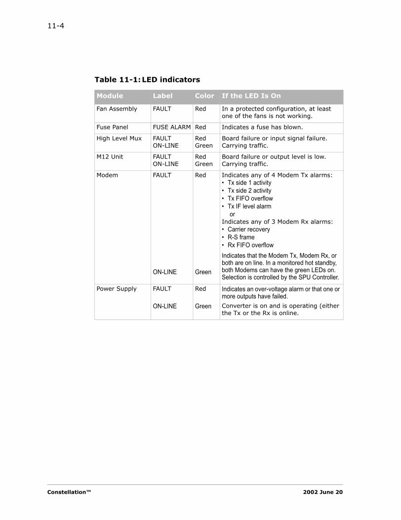
11-4
Table 11-1:LED indicators
Module Label Color If the LED Is On
Fan Assembly FAULT Red In a protected configuration, at least one of the fans is not working.
Fuse Panel FUSE ALARM Red Indicates a fuse has blown.
High Level Mux FAULTON-LINE
RedGreen
Board failure or input signal failure.Carrying traffic.
M12 Unit FAULTON-LINE
RedGreen
Board failure or output level is low.Carrying traffic.
Modem FAULT
ON-LINE
Red
Green
Indicates any of 4 Modem Tx alarms:• Tx side 1 activity• Tx side 2 activity• Tx FIFO overflow• Tx IF level alarm
orIndicates any of 3 Modem Rx alarms:• Carrier recovery• R-S frame• Rx FIFO overflowIndicates that the Modem Tx, Modem Rx, or both are on line. In a monitored hot standby, both Modems can have the green LEDs on. Selection is controlled by the SPU Controller.
Power Supply FAULT
ON-LINE
Red
Green
Indicates an over-voltage alarm or that one or more outputs have failed.Converter is on and is operating (either the Tx or the Rx is online.
Constellation™ 2002 June 20

Troubleshooting Guidelines 11-5
TR
OU
BLE
SH
OO
TIN
G
GU
IDELIN
ES
Receiver Assembly
FAULTON-LINE
Red
GreenBoard failure or input signal failure.Carrying traffic.
Service Channel FAULT
ON-LINE
Red
Green
Indicates a board failure or inability to synchronize with the far-end Service Channel.If power is on, this LED is always lighted.
SPU Controller MAJOR
MINOR
STATUS
ACTIVETX
RX
Red
Red
Yellow
GreenGreen
Green
Indicates a loss of traffic (either receive or transmit direction).Indicates a non-traffic-affecting alarm or control has been applied.Indicates a loss of input signal from a customer.Normal condition.Blinks whenever a packet of Ethernet signal is being transmitted.Blinks whenever a packet of Ethernet signal is being received.
Transmitter Assembly
FAULT
ON-LINE
Red
Green
Indicates board failure or an input signal failureCarrying traffic.
Table 11-1:LED indicators (Continued)
Module Label Color If the LED Is On
Harris Corporation Constellation™
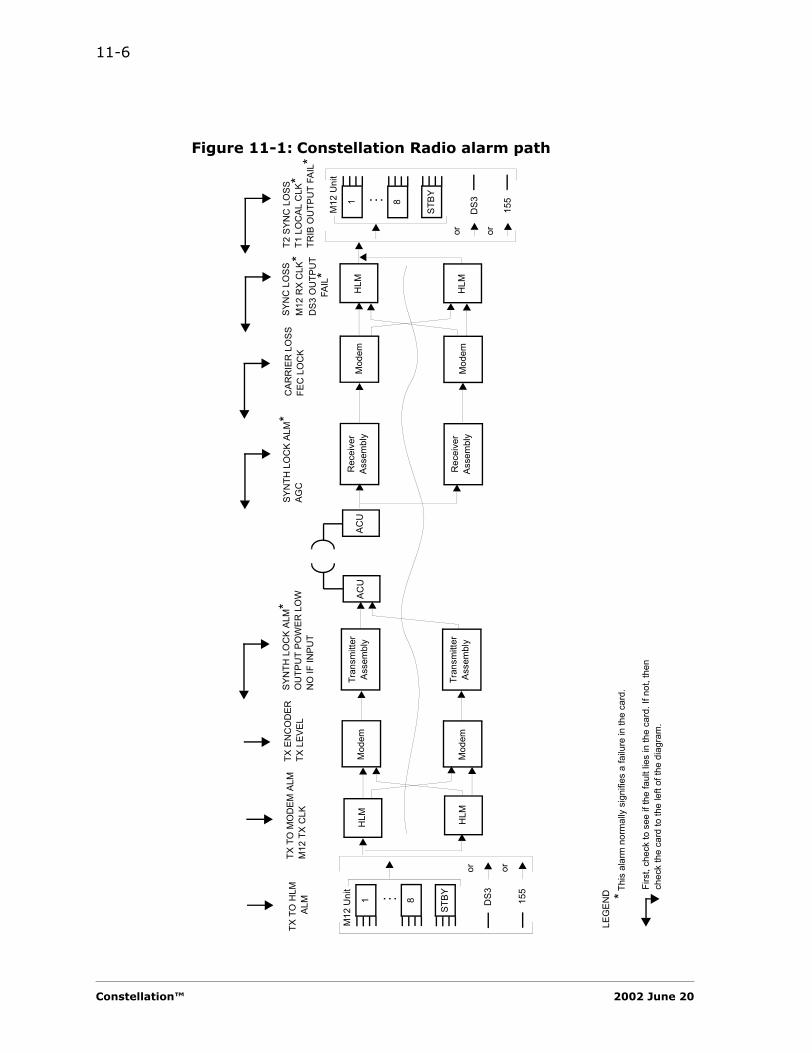
11-6
Figure 11-1: Constellation Radio alarm path
Rec
eive
r As
sem
bly
HLM
Mod
emAC
U
M12
Uni
t
8...
DS3
or
Tran
smitt
er
Asse
mbl
yM
odem
T2 S
YNC
LO
SST1
LO
CAL
CLK
*TR
IB O
UTP
UT
FAIL
*SY
NC
LO
SSM
12 R
X C
LK*
DS3
OU
TPU
T FA
IL*
CAR
RIE
R L
OSS
FEC
LO
CK
SYN
TH L
OC
K AL
M*
AGC
SYN
TH L
OC
K AL
M*
OU
TPU
T PO
WER
LO
WN
O IF
INPU
T
TX E
NC
OD
ERTX
LEV
EL
ACU
HLM
1
STBY
M12
Uni
t
8...
DS3
or
1
STBY
Tran
smitt
er
Asse
mbl
yM
odem
HLM
Rec
eive
r As
sem
bly
HLM
Mod
em
TX T
O M
OD
EM A
LMM
12 T
X C
LKTX
TO
HLM
AL
M * Thi
s al
arm
nor
mal
ly s
igni
fies
a fa
ilure
in th
e ca
rd.
Firs
t, ch
eck
to s
ee if
the
faul
t lie
s in
the
card
. If n
ot, t
hen
chec
k th
e ca
rd to
the
left
of th
e di
agra
m.
LEG
END
155
or
155
or
Constellation™ 2002 June 20
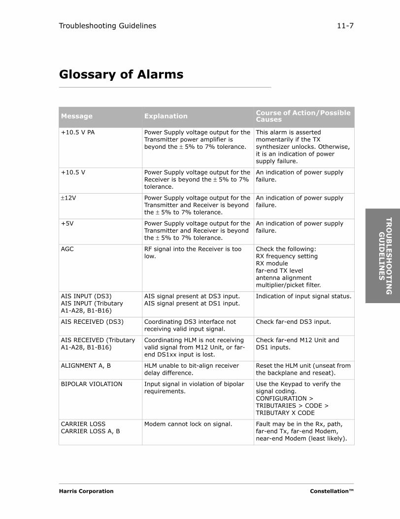
Troubleshooting Guidelines 11-7
TR
OU
BLE
SH
OO
TIN
G
GU
IDELIN
ES
Glossary of Alarms
Message Explanation Course of Action/Possible Causes
+10.5 V PA Power Supply voltage output for the Transmitter power amplifier is beyond the ± 5% to 7% tolerance.
This alarm is asserted momentarily if the TX synthesizer unlocks. Otherwise, it is an indication of power supply failure.
+10.5 V Power Supply voltage output for the Receiver is beyond the ± 5% to 7% tolerance.
An indication of power supply failure.
±12V Power Supply voltage output for the Transmitter and Receiver is beyond the ± 5% to 7% tolerance.
An indication of power supply failure.
+5V Power Supply voltage output for the Transmitter and Receiver is beyond the ± 5% to 7% tolerance.
An indication of power supply failure.
AGC RF signal into the Receiver is too low.
Check the following:RX frequency settingRX modulefar-end TX levelantenna alignmentmultiplier/picket filter.
AIS INPUT (DS3)AIS INPUT (Tributary A1-A28, B1-B16)
AIS signal present at DS3 input.AIS signal present at DS1 input.
Indication of input signal status.
AIS RECEIVED (DS3) Coordinating DS3 interface not receiving valid input signal.
Check far-end DS3 input.
AIS RECEIVED (Tributary A1-A28, B1-B16)
Coordinating HLM is not receiving valid signal from M12 Unit, or far-end DS1xx input is lost.
Check far-end M12 Unit and DS1 inputs.
ALIGNMENT A, B HLM unable to bit-align receiver delay difference.
Reset the HLM unit (unseat from the backplane and reseat).
BIPOLAR VIOLATION Input signal in violation of bipolar requirements.
Use the Keypad to verify the signal coding.CONFIGURATION > TRIBUTARIES > CODE > TRIBUTARY X CODE
CARRIER LOSSCARRIER LOSS A, B
Modem cannot lock on signal. Fault may be in the Rx, path, far-end Tx, far-end Modem, near-end Modem (least likely).
Harris Corporation Constellation™

11-8
CONFIG ALM (configuration alarm)
Caused if 2 or more of the following modules are changed simultaneously:Power Supply A1Transmitter Assembly A1SPU Controller
Use the Keypad to check the configuration of the radio.If all of the configuration are correct, clear the alarm.If not, reconfigure the radio.
Clearing the CONFIG ALM can drop traffic.
DEMOD The HLM is not receiving proper signals from the Modem.
Replace the Modem.
DS3-1, 2, 3 BPV Input signal in violation of bipolar requirements at designated channel.
Use the Keypad to verify the signal coding.CONFIGURATION > TRIBUTARIES > CODE > TRIBUTARY X CODE
DS3-1, 2, 3 INPUT LOS No T3 signal present at designated DS3 input.
Check DS3 input signals.
DS3-1, 2, 3 LOOPBACK The signal on the channel is in loopback mode locally.
Clear the loopback from local radio.CONTROL > TRIB LOOPBACK > DS3 LPBK > CLR
DS3-1, 2, 3 LPBK BY REMOT
The signal on the channel is looped back on HLM towards the Modem.This signal was sent by remote radio.
Clear loopback by remote from remote radio.
DS3-1, 2, 3 OUTPUT FAIL No DS3 output signal or signal level too low (-3 dB) from the designated DS3 channel.
Incorrect output load; failed HLM/
DS3-1, 2, 3 REMOTE LPBK Loopback test of the channel from the far end.
Clear remote loopback from local radio.CONTROL > TRIB LOOPBACK > DS3 LPBK > CLR
DS3 LPBK T3 signal is looped back on HLM towards the Modem.
Clear the loopback from local radio.CONTROL > TRIB LOOPBACK > DS3 LPBK > CLR
EXTERNAL ALARM (1-8) Alarm input is at logic low or ground.
These are customer’s own alarms.
Message Explanation Course of Action/Possible Causes
Constellation™ 2002 June 20
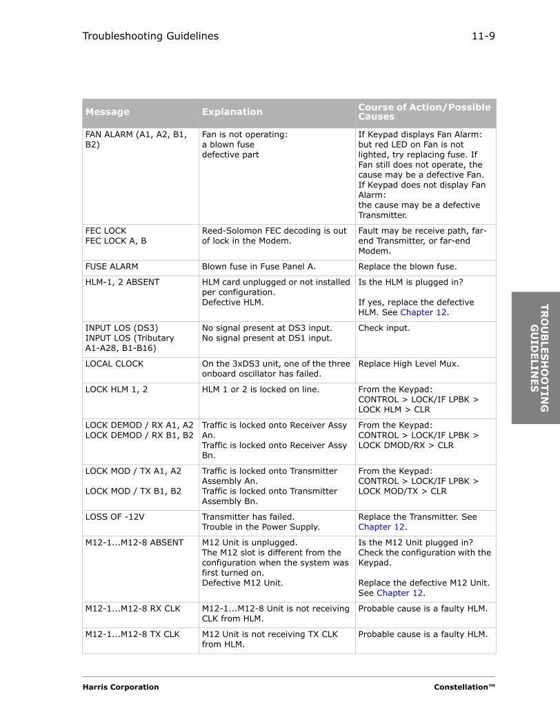
Troubleshooting Guidelines 11-9
TR
OU
BLE
SH
OO
TIN
G
GU
IDELIN
ES
FAN ALARM (A1, A2, B1, B2)
Fan is not operating:a blown fusedefective part
If Keypad displays Fan Alarm: but red LED on Fan is not lighted, try replacing fuse. If Fan still does not operate, the cause may be a defective Fan.If Keypad does not display Fan Alarm:the cause may be a defective Transmitter.
FEC LOCKFEC LOCK A, B
Reed-Solomon FEC decoding is out of lock in the Modem.
Fault may be receive path, far-end Transmitter, or far-end Modem.
FUSE ALARM Blown fuse in Fuse Panel A. Replace the blown fuse.
HLM-1, 2 ABSENT HLM card unplugged or not installed per configuration.Defective HLM.
Is the HLM is plugged in?
If yes, replace the defective HLM. See Chapter 12.
INPUT LOS (DS3)INPUT LOS (Tributary A1-A28, B1-B16)
No signal present at DS3 input.No signal present at DS1 input.
Check input.
LOCAL CLOCK On the 3xDS3 unit, one of the three onboard oscillator has failed.
Replace High Level Mux.
LOCK HLM 1, 2 HLM 1 or 2 is locked on line. From the Keypad:CONTROL > LOCK/IF LPBK > LOCK HLM > CLR
LOCK DEMOD / RX A1, A2LOCK DEMOD / RX B1, B2
Traffic is locked onto Receiver Assy An.Traffic is locked onto Receiver Assy Bn.
From the Keypad:CONTROL > LOCK/IF LPBK > LOCK DMOD/RX > CLR
LOCK MOD / TX A1, A2
LOCK MOD / TX B1, B2
Traffic is locked onto Transmitter Assembly An.Traffic is locked onto Transmitter Assembly Bn.
From the Keypad:CONTROL > LOCK/IF LPBK > LOCK MOD/TX > CLR
LOSS OF -12V Transmitter has failed.Trouble in the Power Supply.
Replace the Transmitter. See Chapter 12.
M12-1...M12-8 ABSENT M12 Unit is unplugged.The M12 slot is different from the configuration when the system was first turned on.Defective M12 Unit.
Is the M12 Unit plugged in?Check the configuration with the Keypad.
Replace the defective M12 Unit. See Chapter 12.
M12-1...M12-8 RX CLK M12-1...M12-8 Unit is not receiving CLK from HLM.
Probable cause is a faulty HLM.
M12-1...M12-8 TX CLK M12 Unit is not receiving TX CLK from HLM.
Probable cause is a faulty HLM.
Message Explanation Course of Action/Possible Causes
Harris Corporation Constellation™

11-10
M12 FILLER MISSING Filler Unit is missing from unused M12 slot.
Install a Filler Unit in the missing slot.
M12 STBY ABSENT M12 Unit is unplugged from the M12 Standby slot.M12 Unit is not equipped per configuration.Defective M12 card.
Is the M12 Unit plugged in?
Install an M12 Unit.
Replace the M12 Unit. See Chapter 12.
M12-STBY RX CLK HLM is not receiving CLK from M12-Standby Unit.
Replace the M12 Unit in the M12 Standby slot.
M12-STBY TX CLK M12 Standby Unit is not receiving TX CLK from HLM.
Replace the High Level Mux with the red (Fault) LED lighted.
M13 SYNC LOSS Loss of frame for selected DS3 to be demuxed.
Check far-end High Level Mux and configuration.
MANUAL MUTE TX power switch on the Transmitter Assembly is OFF.
On the Transmitter Assembly faceplate, press the Tx switch to the ON position.
MODEM ABSENT (A1, A2 / B1, B2)
Modem card unplugged.Modem not installed per configuration.Defective Modem.
Is the Modem plugged in?Install Modem.
Replace the Modem. See Chapter 12.
MODEM A, B IF LPBK Modem A or B in loopback mode (local command only).
Cancel the IF loopback test.
NO ETHERNET ADDRESS Address not assigned; unique address provided by Harris.
Return SPU Controller to Harris.
NO IF INPUT Loss of signal from the Modem to the Transmitter.
Check the cable connecting the Modem to the Transmitter. If the cable is okay, replace the Modem.
OC3 INPUT LOS No signal present at transceiver of HLM-155.
Check the input signal from the external equipment.
OC3 LPBK The OC3 signal is in loopback mode locally.
Clear the loopback test from the local radio.CONTROL > hidden menu
OC3 LPBK BY REMOTE The OC3 signal is looped back on HLM towards the Modem.
Clear loopback by remote test from the remote radio.
OC3 REMOTE LPBK OC3 signal loopback test from the far end.
Clear remote loopback test from the local radio.CONTROL > hidden menu
OC3 RX LOF Loss of frame into HLM-155 from Hi Cap Modem.
Check Modem alarms.
OC3 TX LOF Loss of frame into HLM-155 from customer.
Check input signal from external equipment.
Message Explanation Course of Action/Possible Causes
Constellation™ 2002 June 20

Troubleshooting Guidelines 11-11
TR
OU
BLE
SH
OO
TIN
G
GU
IDELIN
ES
ONLINE ALIGNMENT A, B HLM unable to bit-align receiver delay difference. Rx switching will not be errorless.
Check Modem alarms.
OUTPUT FAIL(DS3, Tributary, Wayside)
No output signal or signal level too low (-3 dB).
Check for improper line termination.Replace High Level Mux.
OUTPUT POWER LOW RF output level from the Transmitter Assembly is at least 3 dB low.
Check configuration.Could be a bad multiplier/picket filter.Replace Transmitter.
PROTECT M12-1 ... M12-8 Designated M12 Unit is protected by a standby M12 Unit.
Check M12 Unit. Replace the Unit if needed.
PS ABSENT (A1, A2 / B1, B2)
Power Supply unplugged.Power Supply not installed per configuration.Defective Power Supply.
Is the Power Supply plugged in?Install Power Supply card.
Replace the Power Supply. See Chapter 12.
REMOTE SYNC LOSS A, B Coordinating loss of framing at the far end.
Start the troubleshooting of the far-end radio.
RSL LOW A1,A2 / B1,B2 RF level into Receiver Assembly < 10 dB above system threshold.
Check the following:Receiver frequency settingReceiver Assemblyfar-end Transmitter levelantenna alignmentmultiplier/picket filter
RX ABSENT (A1, A2 / B1, B2)
Receiver Assembly unplugged or not installed per configuration.
Power Supply turned off.
Defective Receiver Assembly.
Ensure that the Receiver Assembly is plugged into the backplane.If all 3 RF cards show absent alarms, the trouble is most likely to be in the Power Supply. Replace the PS card.Before turning on the PS, turn off the Tx.Replace the Receiver Assembly. See Chapter 12.
RX DECODER Modem decoder is in alarm state. Fault may be inThe Receiver The pathFar-end TransmitterFar-end ModemNear-end Modem (least likely).
Message Explanation Course of Action/Possible Causes
Harris Corporation Constellation™

11-12
RX LOSS OF FRAME Local loss of framing of incoming signal.
Fault may be inThe Receiver The pathFar-end TransmitterFar-end ModemNear-end Modem (least likely).
SIGNAL DEGRADED A, B(TRAFFIC A, B)(PATH A, B)
Signal quality after equalization is degraded. System RSL or BER may be close to threshold.
Fault may be receive path or far-end Transmitter.
SVC ABSENT Service Channel unplugged or missing.
Ensure that the Service Channel is plugged into the backplane.From the Keypad, CONFIGURATION > SYSTEM > SVC OPTION > INSTALL puts the Service Channel into service.
SYNTH LOCK(RX-A1, A2 / B1, B2)
SYNTH LOCK(TX-A1, A2 / B1, B2)
2 GHz synthesizer in the Receiver Assembly is out of lock. Frequency is different from the assigned frequency.
2 GHz synthesizer in the Transmitter Assembly is out of lock. Frequency is different from the assigned frequency.
You must enter exactly 7 digits for the frequency, but for 11 GHz systems, you must enter 8 digits. If the frequency is set correctly, either the Rx or the PS may be faulty.You must enter exactly 7 digits for the frequency, but for 11 GHz systems, you must enter 8 digits. If the frequency is set correctly, either the Tx or the PS may be faulty.
SYNC LOSS A, B (HLM-1, 2)SYNC LOSS A, B (SVC)
HLM unable to synchronize to Rx signal.Not receiving Service Channel frame from coordinate Service Channel.
Check Modem alarms.
SYSTEM IS REBOOTING System is rebooting. Do not unplug the SPU Controller.Do not reboot the SPU Controller.Do not download new software.Do not switch software version.
T1 LOCAL CLK T1 CLK failure on M12 Unit. Replace the M12 Unit.
T2 SYNC LOSS M12 Unit cannot frame up to incoming signal.
Check High Level Mux alarms. If okay, check far-end M12 Unit.
TRIB 1...4 OUTPUT FAIL Output signal failure or signal level below alarm threshold.
Check line termination. If okay, replace M12 Unit.
TRIB LPBK (A1...A28, B1...B16)
One or several T1 signals are looped back toward the HLM.
Clear by Keypad command:CONTROL > TRIB LOOPBACK > TRIB LPBK > CLR.
Message Explanation Course of Action/Possible Causes
Constellation™ 2002 June 20
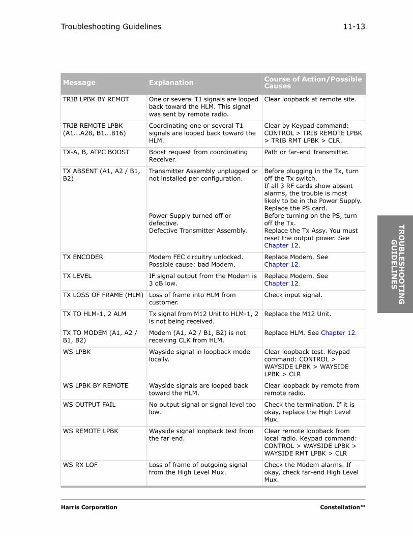
Troubleshooting Guidelines 11-13
TR
OU
BLE
SH
OO
TIN
G
GU
IDELIN
ES
TRIB LPBK BY REMOT One or several T1 signals are looped back toward the HLM. This signal was sent by remote radio.
Clear loopback at remote site.
TRIB REMOTE LPBK (A1...A28, B1...B16)
Coordinating one or several T1 signals are looped back toward the HLM.
Clear by Keypad command:CONTROL > TRIB REMOTE LPBK > TRIB RMT LPBK > CLR.
TX-A, B, ATPC BOOST Boost request from coordinating Receiver.
Path or far-end Transmitter.
TX ABSENT (A1, A2 / B1, B2)
Transmitter Assembly unplugged or not installed per configuration.
Power Supply turned off or defective.Defective Transmitter Assembly.
Before plugging in the Tx, turn off the Tx switch.If all 3 RF cards show absent alarms, the trouble is most likely to be in the Power Supply. Replace the PS card.Before turning on the PS, turn off the Tx.Replace the Tx Assy. You must reset the output power. See Chapter 12.
TX ENCODER Modem FEC circuitry unlocked. Possible cause: bad Modem.
Replace Modem. See Chapter 12.
TX LEVEL IF signal output from the Modem is 3 dB low.
Replace Modem. See Chapter 12.
TX LOSS OF FRAME (HLM) Loss of frame into HLM from customer.
Check input signal.
TX TO HLM-1, 2 ALM Tx signal from M12 Unit to HLM-1, 2 is not being received.
Replace the M12 Unit.
TX TO MODEM (A1, A2 / B1, B2)
Modem (A1, A2 / B1, B2) is not receiving CLK from HLM.
Replace HLM. See Chapter 12.
WS LPBK Wayside signal in loopback mode locally.
Clear loopback test. Keypad command: CONTROL > WAYSIDE LPBK > WAYSIDE LPBK > CLR
WS LPBK BY REMOTE Wayside signals are looped back toward the HLM.
Clear loopback by remote from remote radio.
WS OUTPUT FAIL No output signal or signal level too low.
Check the termination. If it is okay, replace the High Level Mux.
WS REMOTE LPBK Wayside signal loopback test from the far end.
Clear remote loopback from local radio. Keypad command: CONTROL > WAYSIDE LPBK > WAYSIDE RMT LPBK > CLR
WS RX LOF Loss of frame of outgoing signal from the High Level Mux.
Check the Modem alarms. If okay, check far-end High Level Mux.
Message Explanation Course of Action/Possible Causes
Harris Corporation Constellation™

11-14
Constellation™ 2002 June 20

FIE
LD-
REP
LA
CEA
BLE
UN
ITS
C H A P T E R
12FIELD-REPLACEABLE UNITS
Precautions
Electric Parts
Wear a grounded antistatic wrist strap or heel strap prior to opening electrostatic discharge (ESD) protective packaging and while handling any unprotected electric parts.
Avoid touching the edge connectors with your fingers.
Harris Corporation Constellation™
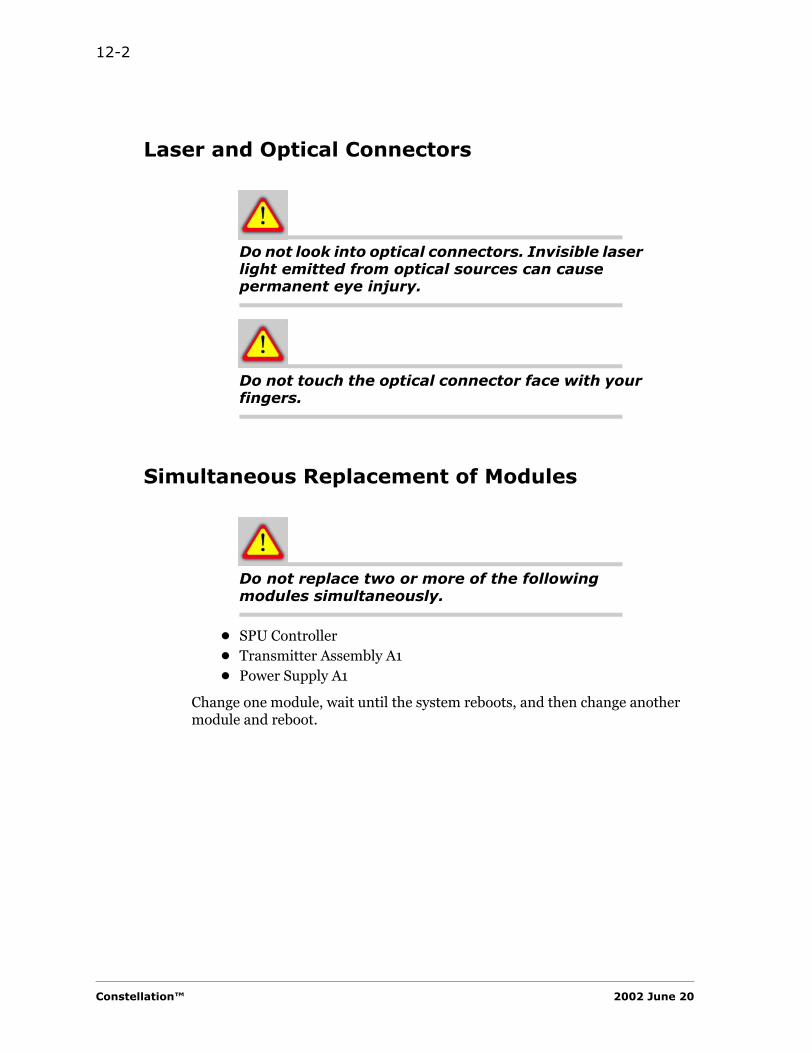
12-2
Laser and Optical Connectors
Do not look into optical connectors. Invisible laser light emitted from optical sources can cause permanent eye injury.
Do not touch the optical connector face with your fingers.
Simultaneous Replacement of Modules
Do not replace two or more of the following modules simultaneously.
• SPU Controller• Transmitter Assembly A1• Power Supply A1
Change one module, wait until the system reboots, and then change another module and reboot.
Constellation™ 2002 June 20
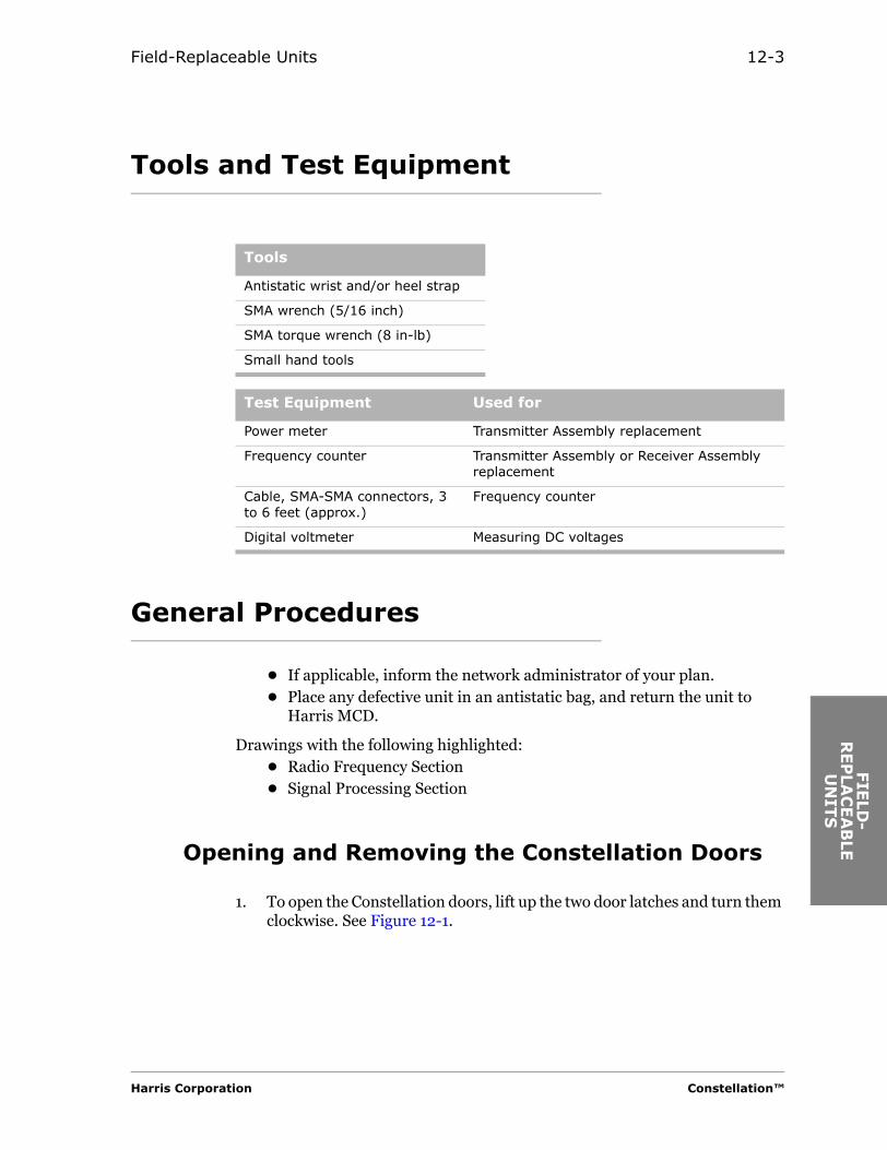
Field-Replaceable Units 12-3
FIE
LD
-R
EP
LAC
EA
BLE
U
NIT
S
Tools and Test Equipment
General Procedures
• If applicable, inform the network administrator of your plan.• Place any defective unit in an antistatic bag, and return the unit to
Harris MCD.
Drawings with the following highlighted:• Radio Frequency Section• Signal Processing Section
Opening and Removing the Constellation Doors
1. To open the Constellation doors, lift up the two door latches and turn them clockwise. See Figure 12-1.
Tools
Antistatic wrist and/or heel strap
SMA wrench (5/16 inch)
SMA torque wrench (8 in-lb)
Small hand tools
Test Equipment Used for
Power meter Transmitter Assembly replacement
Frequency counter Transmitter Assembly or Receiver Assembly replacement
Cable, SMA-SMA connectors, 3 to 6 feet (approx.)
Frequency counter
Digital voltmeter Measuring DC voltages
Harris Corporation Constellation™

12-4
Figure 12-1: Constellation Radio, front view
2. The doors swing open 90 degrees.
3. For radios with straps (Figure 12-2) installed inside the door:
Pull the straps (on the left and right sides) to unfasten them.
Figure 12-2: Door straps
4. Lift up the doors to remove them from the card cage.
Left strap Right strap
Constellation™ 2002 June 20

Field-Replaceable Units 12-5
FIE
LD
-R
EP
LAC
EA
BLE
U
NIT
S
Fan Assembly
Figure 12-3: The Constellation Radio (with doors removed), repeater
If the Constellation radio is in service, the Fan Assembly must be operating within 10 minutes of removal and installation.
Removing the Fan Assembly
1. For a terminal, remove the Keypad and place it temporarily out of the way. See Figures 12-1.
TRAN
SM
ITTER B
1
RECEIV
ER B
1
PO
WER S
UPPLY
B1
TRAN
SM
ITTER B
2
RECEIV
ER B
2
PO
WER S
UPPLY
B2
MO
DEM
A2
HIG
H LE
VEL M
UX 1
MO
DEM
B2
HIG
H LE
VEL M
UX 1
SERVIC
E C
HAN
NEL
SPU
CO
NTRO
LLER
MO
DEM
B1
MO
DEM
A1
TRAN
SM
ITTER A
1
RECEIV
ER A
1
PO
WER S
UPPLY
A1
TRAN
SM
ITTER A
2
RECEIV
ER A
2
PO
WER S
UPPLY
A2
ACU
FUSE PANEL
M12 Units not used for
DS3 config-uration
ACU
FUSE PANEL
FAN ASSEMBLY
KEYPAD, HANDSET, AND DS1 ACCESS
FAN ASSEMBLY
Harris Corporation Constellation™
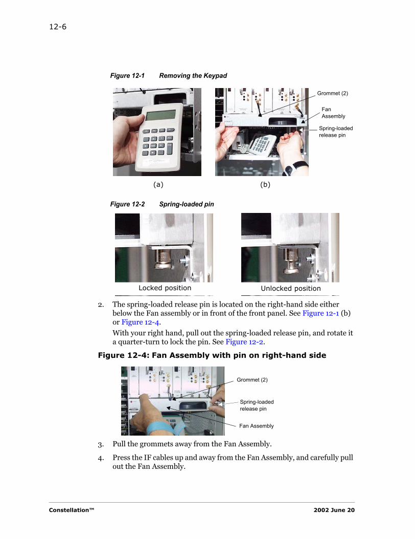
12-6
Figure 12-1 Removing the Keypad
Figure 12-2 Spring-loaded pin
2. The spring-loaded release pin is located on the right-hand side either below the Fan assembly or in front of the front panel. See Figure 12-1 (b) or Figure 12-4.
With your right hand, pull out the spring-loaded release pin, and rotate it a quarter-turn to lock the pin. See Figure 12-2.
Figure 12-4: Fan Assembly with pin on right-hand side
3. Pull the grommets away from the Fan Assembly.
4. Press the IF cables up and away from the Fan Assembly, and carefully pull out the Fan Assembly.
Spring-loaded release pin
Fan Assembly
(a) (b)
Grommet (2)
Locked position Unlocked position
Spring-loaded release pin
Fan Assembly
Grommet (2)
Constellation™ 2002 June 20
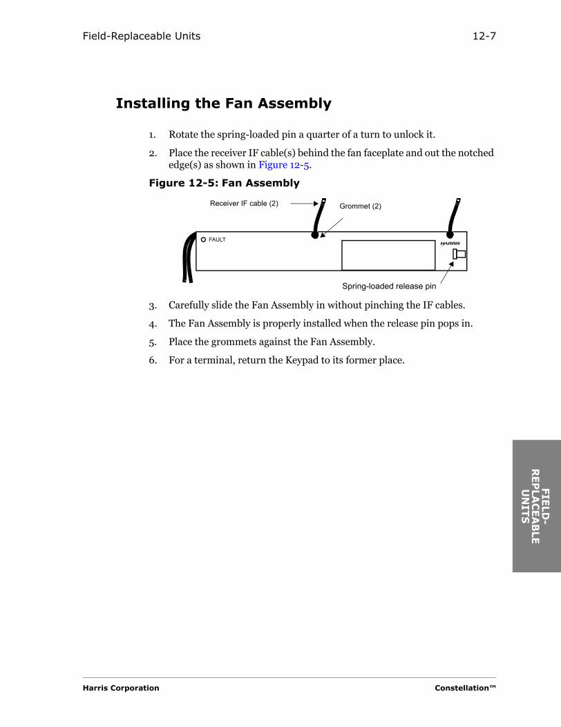
Field-Replaceable Units 12-7
FIE
LD
-R
EP
LAC
EA
BLE
U
NIT
S
Installing the Fan Assembly
1. Rotate the spring-loaded pin a quarter of a turn to unlock it.
2. Place the receiver IF cable(s) behind the fan faceplate and out the notched edge(s) as shown in Figure 12-5.
Figure 12-5: Fan Assembly
3. Carefully slide the Fan Assembly in without pinching the IF cables.
4. The Fan Assembly is properly installed when the release pin pops in.
5. Place the grommets against the Fan Assembly.
6. For a terminal, return the Keypad to its former place.
FAULT
Receiver IF cable (2)
Spring-loaded release pin
Grommet (2)
Harris Corporation Constellation™
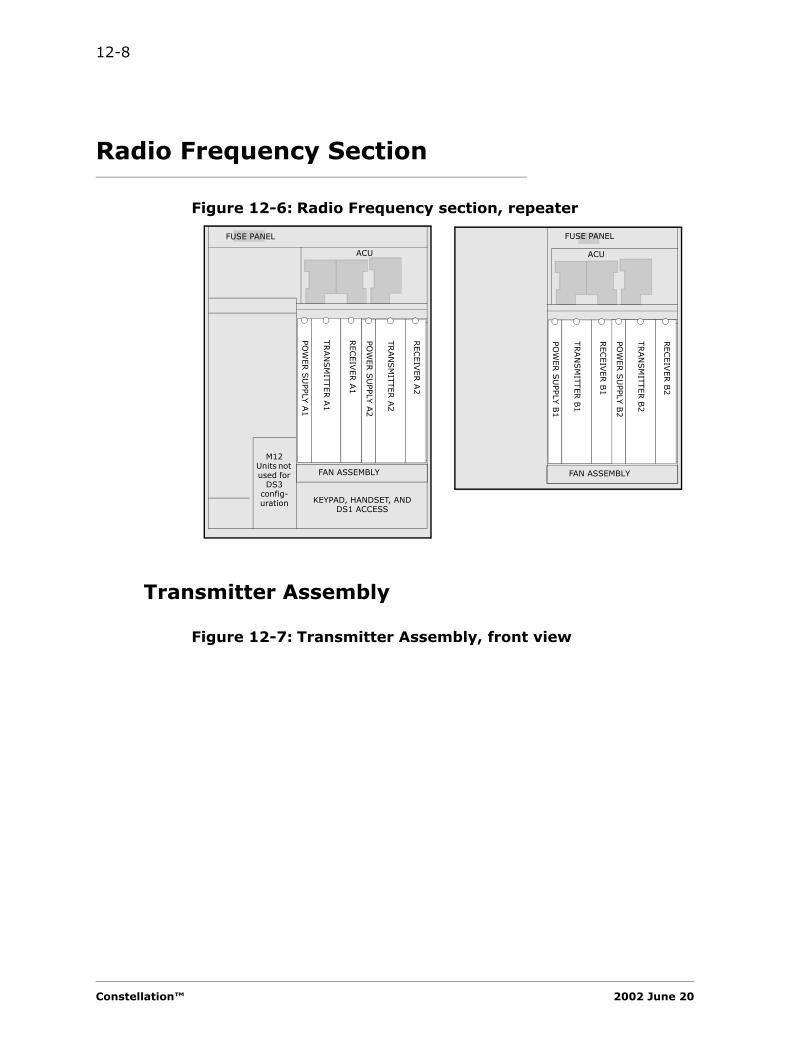
12-8
Radio Frequency Section
Figure 12-6: Radio Frequency section, repeater
Transmitter Assembly
Figure 12-7: Transmitter Assembly, front view
TRAN
SM
ITTER A
1
RECEIV
ER A
1
ACU
FUSE PANEL
FAN ASSEMBLY
POW
ER S
UPPLY
A1
M12 Units not used for
DS3 config-uration
TRAN
SM
ITTER B
1
RECEIV
ER B
1
ACU
FUSE PANEL
FAN ASSEMBLY
PO
WER S
UPPLY
B1
KEYPAD, HANDSET, AND DS1 ACCESS
TRAN
SM
ITTER A
2
RECEIV
ER A
2
POW
ER S
UPPLY
A2
TRAN
SM
ITTER B
2
RECEIV
ER B
2
POW
ER S
UPPLY
B2
Constellation™ 2002 June 20
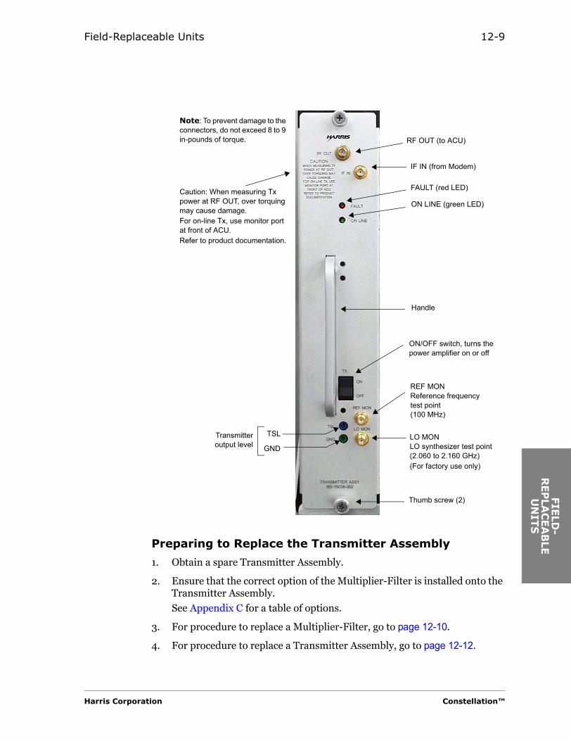
Field-Replaceable Units 12-9
FIE
LD
-R
EP
LAC
EA
BLE
U
NIT
S
Preparing to Replace the Transmitter Assembly
1. Obtain a spare Transmitter Assembly.
2. Ensure that the correct option of the Multiplier-Filter is installed onto the Transmitter Assembly.
See Appendix C for a table of options.
3. For procedure to replace a Multiplier-Filter, go to page 12-10.
4. For procedure to replace a Transmitter Assembly, go to page 12-12.
Note: To prevent damage to the connectors, do not exceed 8 to 9 in-pounds of torque.
IF IN (from Modem)
RF OUT (to ACU)
Thumb screw (2)
Transmitteroutput level
LO MONLO synthesizer test point(2.060 to 2.160 GHz)(For factory use only)
REF MONReference frequencytest point(100 MHz)
ON/OFF switch, turns the power amplifier on or off
FAULT (red LED)
ON LINE (green LED)
TSL
GND
Handle
Caution: When measuring Tx power at RF OUT, over torquing may cause damage.For on-line Tx, use monitor port at front of ACU.Refer to product documentation.
Harris Corporation Constellation™

12-10
Removing and Installing the Multiplier-Filter
1. Unplug the MCX connector. See Figure 12-8.
Figure 12-8: Transmitter Assembly, component side
2. Unfasten the screw on the right-hand side of the Multiplier-Filter.
3. Unplug the Multiplier-Filter from the Driver Amplifier by pulling the Multiplier-Filter to the right.
Ensure that the Multiplier-Filter you are installing is the correct option.
4. Reverse the previous three steps to install the Multiplier-Filter onto the Transmitter Assembly.
Multiplier-filter(field-replaceable)
Screw
Driversubassembly MCX connector
AB
SOFTWARE FAULTHARDWARE FAULT
JP1
Power amplifier
Note: JP1 settings are for factory use only. Do not touch.
100 MHz OCXO-amplifier
SMA cablePower connector
MCX connector
100MHZ
Constellation™ 2002 June 20
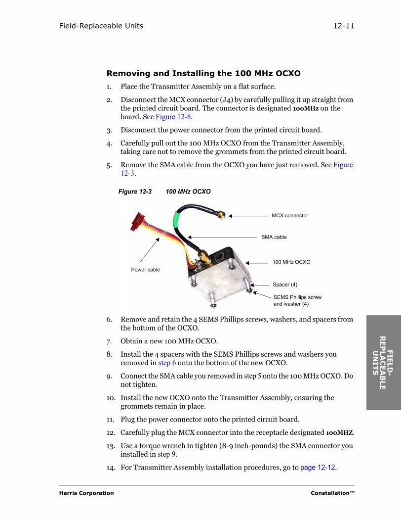
Field-Replaceable Units 12-11
FIE
LD
-R
EP
LAC
EA
BLE
U
NIT
S
Removing and Installing the 100 MHz OCXO
1. Place the Transmitter Assembly on a flat surface.
2. Disconnect the MCX connector (J4) by carefully pulling it up straight from the printed circuit board. The connector is designated 100MHz on the board. See Figure 12-8.
3. Disconnect the power connector from the printed circuit board.
4. Carefully pull out the 100 MHz OCXO from the Transmitter Assembly, taking care not to remove the grommets from the printed circuit board.
5. Remove the SMA cable from the OCXO you have just removed. See Figure 12-3.
Figure 12-3 100 MHz OCXO
6. Remove and retain the 4 SEMS Phillips screws, washers, and spacers from the bottom of the OCXO.
7. Obtain a new 100 MHz OCXO.
8. Install the 4 spacers with the SEMS Phillips screws and washers you removed in step 6 onto the bottom of the new OCXO.
9. Connect the SMA cable you removed in step 5 onto the 100 MHz OCXO. Do not tighten.
10. Install the new OCXO onto the Transmitter Assembly, ensuring the grommets remain in place.
11. Plug the power connector onto the printed circuit board.
12. Carefully plug the MCX connector into the receptacle designated 100MHZ.
13. Use a torque wrench to tighten (8-9 inch-pounds) the SMA connector you installed in step 9.
14. For Transmitter Assembly installation procedures, go to page 12-12.
SEMS Phillips screw and washer (4)
100 MHz OCXOPower cable
MCX connector
SMA cable
Spacer (4)
Harris Corporation Constellation™
12-12
Removing the Transmitter Assembly• In a MHSB configuration, start with step 1.• In a nonprotected configuration, start with step 3.
In a nonprotected configuration, removing the Transmitter Assembly is a service-affecting procedure.
1. Use the Keypad command to lock traffic onto the standby Transmitter and Receiver Assemblies. This step causes a minor alarm.
CONTROL > LOCK/IF LPBK > LOCK MOD/TX, SETCONTROL > LOCK/IF LPBK > LOCK DMOD/RX, SET
Since switching of Transmitter Assembly is not errorless, this procedure momentarily affects customer traffic.
2. Verify that the standby Transmitter and Receiver Assemblies are locked and passing traffic.
3. On the Transmitter Assembly you are removing, press the TX switch to the OFF position to turn off the power amplifier.
4. On the corresponding Power Supply, press the PWR switch to the OFF position to turn off the power supply.
5. Disconnect the two cables on the Transmitter Assembly.• The cable connected to the IF IN SMA connector• The cable connected to the ACU
6. Unfasten the 2 captive thumbscrews.
7. Carefully pull out the Transmitter Assembly from the shelf.
Installing the Transmitter Assembly
Before plugging the spare Transmitter Assembly into the Constellation card cage, the correct
Constellation™ 2002 June 20
Field-Replaceable Units 12-13
FIE
LD
-R
EP
LAC
EA
BLE
U
NIT
S
option of the Multiplier-Filter must be installed onto the board.
See page 12-10 for ““Removing and Installing the Multiplier-Filter””.
1. Check the part number of the Transmitter Assembly to ensure that the correct unit is being installed.
2. Ensure that the • TX switch on the Transmitter Assembly faceplate is in the OFF position.• PWR switch on the Power Supply is in the OFF position.
3. Carefully slide the Transmitter Assembly into the designated slot in the shelf until the unit plugs into the backplane.
4. Use the 2 thumbscrews to fasten the unit to the shelf.
5. On the faceplate, reconnect the cables onto the SMA connector.• IF IN (from the Modem)• RF OUT (to the ACU)
6. Use a torque wrench to tighten the connector (8 to 9 in-lb).
7. On the Power Supply, press the PWR switch to the ON position to turn on the power supply.
On the Transmitter Assembly, press the TX switch to the ON position to turn on the power amplifier.
Transmitter Turn-on Procedure
Consult your system administrator for Keypad access to the controls of this procedure.
Table 12-1:Required test equipment
Test Equipment Model
Universal Frequency Counter with 10-digit accuracy
Agilent 53131A or equivalent
Power meter with power sensor Agilent E4418B and 8485Aor equivalent
Harris Corporation Constellation™
12-14
Power levels of 10 watts are possible at the TX OUT connector. Verify that your power meter is capable of handling such levels, or use correct RF padding to protect the power meter.
Go to page 9-3, and follow the "General Measurements Procedure".
MHSB System
1. Use the Keypad command to take the switched unit out of lock status.
CONTROL > LOCK/IF LPBK > LOCK MOD/TX, CLR
CONTROL > LOCK/IF LPBK > LOCK DMOD/RX, CLR
2. The standby RF units are now the primary RF units.
Switching the traffic back to the previous RF units will cause a hit.
3. If switching of RF units is desired, it should be done during low-traffic hours.
Constellation™ 2002 June 20
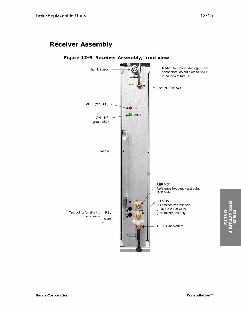
Field-Replaceable Units 12-15
FIE
LD
-R
EP
LAC
EA
BLE
U
NIT
S
Receiver Assembly
Figure 12-9: Receiver Assembly, front view
Note: To prevent damage to the connectors, do not exceed 8 to 9 in-pounds of torque.
RF IN (from ACU)
IF OUT (to Modem)
Thumb screw
REF MON Reference frequency test point (100 MHz)
Test points for aligningthe antenna
FAULT (red LED)
ON LINE(green LED)
RSL
GND
Handle
LO MONLO synthesizer test point(2.060 to 2.160 GHz)(For factory use only)
Harris Corporation Constellation™

12-16
Preparing to Replace the Receiver Assembly
1. Obtain a spare Receiver Assembly.
2. Ensure that the correct option of the Multiplier-Filter is installed onto the Receiver Assembly.
See Appendix C for a table of options.
3. For procedure to replace a Multiplier-Filter, go to page 12-16.
4. Ensure that the correct option of the IF filter is installed onto the Receiver Assembly.
Refer to page 12-17.
5. For procedure to replace a Receiver Assembly, go to page 12-19.
Removing and Installing the Multiplier-Filter
1. Unplug the MCX connector. See Figure 12-10.
Figure 12-10:Receiver Assembly, component side
2. Unfasten the screw on the right-hand side of the Multiplier-Filter.
3. Unplug the Multiplier-Filter from the LNC by pulling the Multiplier-Filter to the right.
INO
UT
Multiplier-filter(field-replaceable)
IF filter(field-replaceable)
Screw
LNC MCX connector
AB
SOFTWARE FAULTHARDWARE FAULT
JP1
SMA connector (2)
Mounting bracket
Mounting screw (2)
Note: JP1 settings are for factory use only. Do not touch.
Note: To prevent damage to the connectors, do not exceed 8 to 9 in-pounds of torque.
100 MHzOCXO-amplifier
SMA cablePower connector
MCX connector
100MHZ
Constellation™ 2002 June 20
Field-Replaceable Units 12-17
FIE
LD
-R
EP
LAC
EA
BLE
U
NIT
S
Ensure that the Multiplier-Filter you are installing is the correct option.
4. Reverse the previous three steps to install the Multiplier-Filter onto the Receiver Assembly.
Removing and Installing the IF Filter
1. Gently unscrew the SMA connectors. See Figure 12-10.
2. Carefully move the cables out of the way.
3. Loosen the mounting screws to remove the mounting bracket and IF Filter from the board.
4. Loosen the SMA nuts on the connector to remove the IF Filter from the mounting bracket.
5. Insert the replacement IF Filter into the mounting bracket.
If IN and OUT are marked on the IF Filter, ensure that the side marked IN is in the top position as shown in Figure 12-10.
6. Reverse the first four steps to install the IF Filter onto the board.
To prevent damage to the connectors, do not exceed 8 to 9 in-pounds of torque.
Option Bandwidth (MHz)
-001 5.0
-002 10.0
Harris Corporation Constellation™
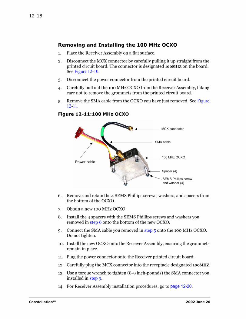
12-18
Removing and Installing the 100 MHz OCXO
1. Place the Receiver Assembly on a flat surface.
2. Disconnect the MCX connector by carefully pulling it up straight from the printed circuit board. The connector is designated 100MHZ on the board. See Figure 12-10.
3. Disconnect the power connector from the printed circuit board.
4. Carefully pull out the 100 MHz OCXO from the Receiver Assembly, taking care not to remove the grommets from the printed circuit board.
5. Remove the SMA cable from the OCXO you have just removed. See Figure 12-11.
Figure 12-11:100 MHz OCXO
6. Remove and retain the 4 SEMS Phillips screws, washers, and spacers from the bottom of the OCXO.
7. Obtain a new 100 MHz OCXO.
8. Install the 4 spacers with the SEMS Phillips screws and washers you removed in step 6 onto the bottom of the new OCXO.
9. Connect the SMA cable you removed in step 5 onto the 100 MHz OCXO. Do not tighten.
10. Install the new OCXO onto the Receiver Assembly, ensuring the grommets remain in place.
11. Plug the power connector onto the Receiver printed circuit board.
12. Carefully plug the MCX connector into the receptacle designated 100MHZ.
13. Use a torque wrench to tighten (8-9 inch-pounds) the SMA connector you installed in step 9.
14. For Receiver Assembly installation procedures, go to page 12-20.
SEMS Phillips screw and washer (4)
100 MHz OCXOPower cable
MCX connector
SMA cable
Spacer (4)
Constellation™ 2002 June 20
Field-Replaceable Units 12-19
FIE
LD
-R
EP
LAC
EA
BLE
U
NIT
S
Removing the Receiver Assembly• In a MHSB configuration, start with step 1.• In a nonprotected configuration, start with step 2.
In a nonprotected configuration, removing the Receiver Assembly is a service-affecting procedure.
1. Use the Keypad command to lock traffic onto the Receiver Assembly that is not being removed. This step causes a minor alarm.
CONTROL > LOCK/IF LPBK > LOCK DMOD/RX, SET
In a normal operation, switching of Receiver Assembly is an errorless function.
2. Disconnect the cable to the IF OUT SMA connector.
3. Loosen the SMA connector of the cable connected to the ACU.
4. Disconnect the cable connected to RF IN, and rotate it out of the way.
5. Unfasten the captive thumbscrew.
6. Carefully pull out the Receiver Assembly from the shelf.
Before plugging the spare Receiver Assembly into the Constellation card cage, the correct option of the Multiplier-Filter and the IF Filter must be installed onto the board.
Harris Corporation Constellation™
12-20
Installing the Receiver Assembly
1. Check the part number of the Receiver Assembly to ensure that the correct unit is being installed.
2. Carefully slide the Receiver Assembly into the designated slot in the shelf until the unit plugs into the backplane.
3. Use the thumbscrew to fasten the unit to the shelf.
4. On the faceplate, reconnect the cables onto the SMA connectors.• RF IN (from the ACU)• IF OUT (to the Modem)
5. Use a torque wrench to tighten the connectors (8 to 9 in-lb).
6. For testing procedure, refer to page 9-3, and follow the "General Measurements Procedure".
MHSB System
1. Use the Keypad command to take the switched unit out of lock status.
CONTROL > LOCK/IF LPBK > LOCK DMOD/RX, CLR
2. The standby Receiver Assembly is now the primary Receiver Assembly.
Constellation™ 2002 June 20
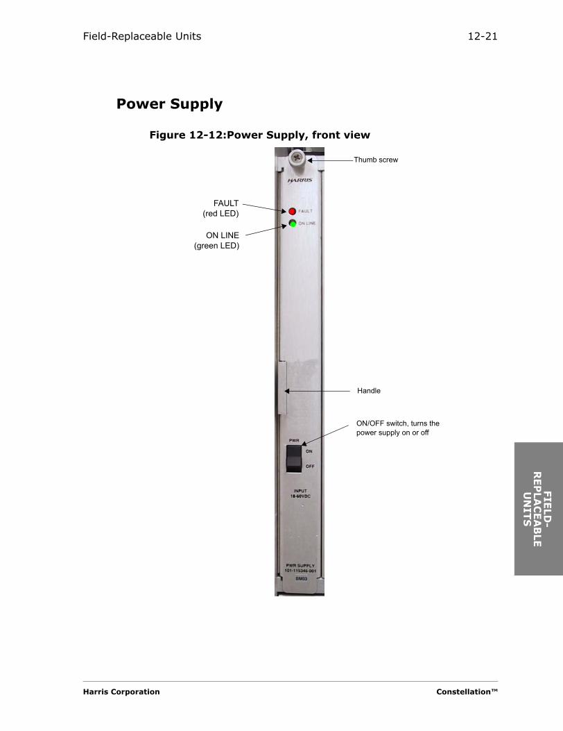
Field-Replaceable Units 12-21
FIE
LD
-R
EP
LAC
EA
BLE
U
NIT
S
Power Supply
Figure 12-12:Power Supply, front view
ON/OFF switch, turns the power supply on or off
FAULT(red LED)
ON LINE(green LED)
Thumb screw
Handle
Harris Corporation Constellation™

12-22
Power Supply Failure
The Power Supply provides power to one Transmitter Assembly and one Receiver Assembly. When the Power Supply fails, the Transmitter and the Receiver Assemblies associated with the Power Supply cannot carry traffic. In a MHSB system, the system automatically switches traffic to the standby units.
Removing the Power Supply• In a MHSB configuration, start with step 1.• In a nonprotected configuration, start with step 2.
1. Use the Keypad commands to lock traffic onto the standby Transmitter and Receiver. This step causes a minor alarm.
CONTROL > LOCK/IF LPBK > LOCK MOD/TX, SET
CONTROL > LOCK/IF LPBK > LOCK DMOD/RX, SET
2. On the Transmitter Assembly, press the TX switch to the OFF position to turn off the power amplifier.
3. Press the PWR switch to the OFF position to turn off the power supply.
4. Unfasten the captive thumbscrew.
5. Carefully pull out the Power Supply from the shelf.
Installing the Power Supply
1. Check the part number of the Power Supply to ensure that the correct unit (or a newer unit) is being installed.
2. Ensure that the PWR switch on the Power Supply faceplate is in the OFF position.
3. Carefully slide the Power Supply into the designated slot in the shelf until the unit plugs into the backplane.
4. Use the thumbscrew to fasten the unit to the shelf.
5. Press the PWR switch to ON.
6. On the Transmitter Assembly, press the TX switch to the ON position to turn on the power amplifier.
MHSB System
1. Use the Keypad command to take the standby units out of lock status.
CONTROL > LOCK/IF LPBK > LOCK MOD/TX, CLR
CONTROL > LOCK/IF LPBK > LOCK DMOD/RX, CLR
2. The standby RF units are now the primary RF units.
Constellation™ 2002 June 20

Field-Replaceable Units 12-23
FIE
LD
-R
EP
LAC
EA
BLE
U
NIT
S
Switching the traffic back to the previous RF units will cause a hit; that is, switching of the Transmitter Assemblies will cause a hit.
3. If switching of RF units is desired, it should be done during low-traffic hours.
Signal Processing Section
Figure 12-13:Signal Processing section
Modem
This section is applicable to the High Capacity Modem also.
MO
DEM
A1
ACU
FUSE PANEL
FAN ASSEMBLY
KEYPAD, HANDSET, AND DS1 ACCESS
MO
DEM
A2
HLM
1H
LM 2
SPU
CO
NTRO
LLER
SERVIC
E C
HAN
NEL
STBYFiller Unit
M12 7M12 6M12 5M12 4M12 3M12 2M12 1
Harris Corporation Constellation™
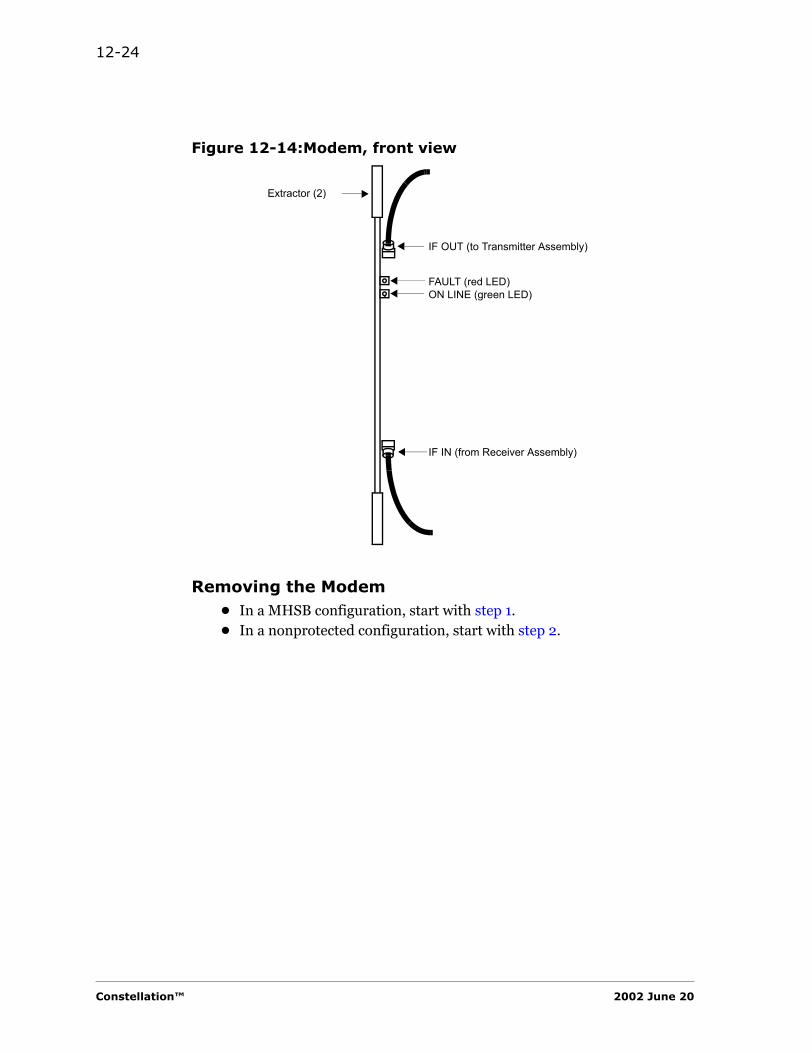
12-24
Figure 12-14:Modem, front view
Removing the Modem• In a MHSB configuration, start with step 1.• In a nonprotected configuration, start with step 2.
Extractor (2)
FAULT (red LED)ON LINE (green LED)
IF OUT (to Transmitter Assembly)
IF IN (from Receiver Assembly)
Constellation™ 2002 June 20

Field-Replaceable Units 12-25
FIE
LD
-R
EP
LAC
EA
BLE
U
NIT
S
In a nonprotected configuration, removing the Modem is a service-affecting procedure.
1. Use the Keypad command to lock traffic on to the Modem that is not being removed. This procedure causes a minor alarm.
CONTROL > LOCK/IF LPBK > LOCK MOD/TX, SET
CONTROL > LOCK/IF LPBK > LOCK DMOD/RX, SET
2. On a repeater system:
On the off-line Power Supply faceplate, turn the PWR switch OFF.
3. Disconnect the cable to the IF OUT SMA connector.
4. Disconnect the cable connected to IF IN SMA connector.
5. Use the 2 extractor tabs to unlock the Modem from the shelf.
6. Carefully pull out the Modem from the shelf.
Installing the Modem
1. Check the part number of the Modem to ensure that the correct unit is being installed.
2. Ensure that the 2 extractors are in the unlocked position.
3. Carefully slide the Modem into the designated slot in the shelf until the unit plugs into the backplane.
4. Use the 2 extractor tabs to lock the unit into place.
5. Reconnect the cables at • IF OUT• IF IN
6. Use a torque wrench to tighten the connectors (8 to 9 in-lb).
7. On a repeater system:
On the Power Supply faceplate, turn the PWR switch ON.
Repeater System
In a repeater system where the Modem units are not the same (that is, one is a Modem and the other is a Cable Modem), ensure that the system synchronization is set to SOURCE timed.
Harris Corporation Constellation™
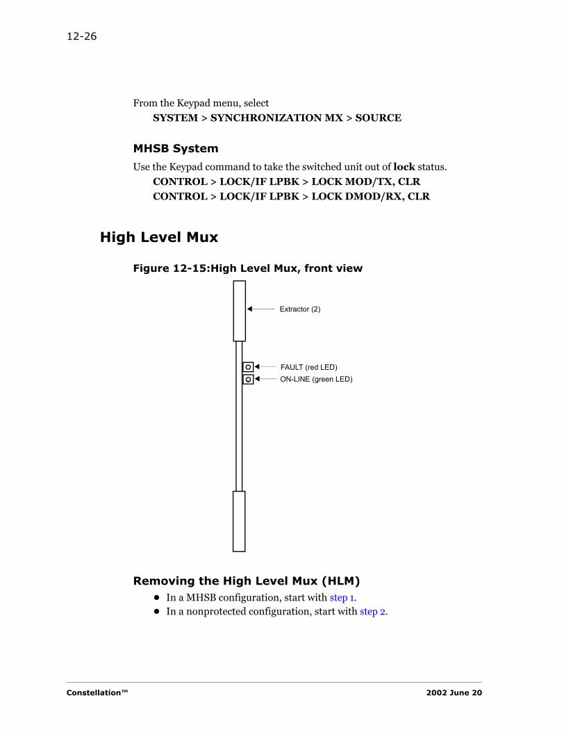
12-26
From the Keypad menu, select
SYSTEM > SYNCHRONIZATION MX > SOURCE
MHSB System
Use the Keypad command to take the switched unit out of lock status.
CONTROL > LOCK/IF LPBK > LOCK MOD/TX, CLR
CONTROL > LOCK/IF LPBK > LOCK DMOD/RX, CLR
High Level Mux
Figure 12-15:High Level Mux, front view
Removing the High Level Mux (HLM)• In a MHSB configuration, start with step 1.• In a nonprotected configuration, start with step 2.
Extractor (2)
FAULT (red LED)ON-LINE (green LED)
Constellation™ 2002 June 20
Field-Replaceable Units 12-27
FIE
LD
-R
EP
LAC
EA
BLE
U
NIT
S
In a nonprotected configuration, removing the HLM is a service-affecting procedure.
1. Use the Keypad command to lock traffic on to the HLM that is not being removed. This step causes a minor alarm.
CONTROL > LOCK/IF LPBK > LOCK HLM, SET
2. Use the 2 extractor tabs to unlock the HLM from the shelf.
3. Carefully pull out the HLM from the shelf.
Installing the HLM
1. Check the part number of the HLM to ensure that the correct unit is being installed.
2. Ensure that the 2 extractors are in the unlocked position.
3. Carefully slide the HLM into the designated slot in the shelf until the unit plugs into the backplane.
4. Use the 2 extractor tabs to lock the unit into place.
Repeater System• In a repeater system where the Modem units are not the same (that is,
one is 115072 and the other is 115430), ensure that the system synchronization is set to SOURCE timed.
• In a loop system, when the HLM is at a master site, the HLM must be set to SOURCE timed.
From the Keypad menu, select
CONFIGURATION > SYSTEM > SYNCHRONIZATION MX > SOURCE
MHSB System
Use the Keypad command to take the switched unit out of lock status.
CONTROL > LOCK/IF LPBK > LOCK HLM, CLR
Harris Corporation Constellation™
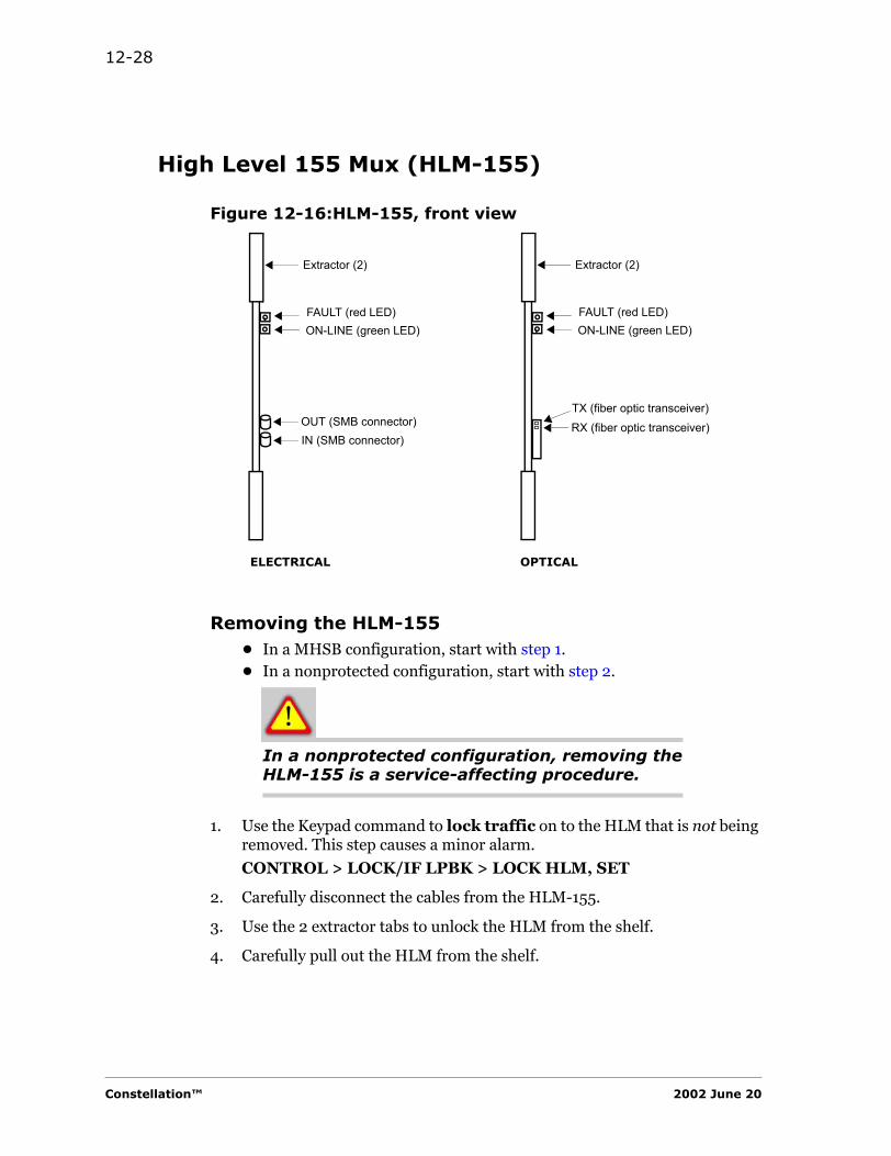
12-28
High Level 155 Mux (HLM-155)
Figure 12-16:HLM-155, front view
Removing the HLM-155• In a MHSB configuration, start with step 1.• In a nonprotected configuration, start with step 2.
In a nonprotected configuration, removing the HLM-155 is a service-affecting procedure.
1. Use the Keypad command to lock traffic on to the HLM that is not being removed. This step causes a minor alarm.
CONTROL > LOCK/IF LPBK > LOCK HLM, SET
2. Carefully disconnect the cables from the HLM-155.
3. Use the 2 extractor tabs to unlock the HLM from the shelf.
4. Carefully pull out the HLM from the shelf.
Extractor (2)
FAULT (red LED)ON-LINE (green LED)
OUT (SMB connector)
Extractor (2)
FAULT (red LED)ON-LINE (green LED)
TX (fiber optic transceiver)
ELECTRICAL OPTICAL
IN (SMB connector)RX (fiber optic transceiver)
Constellation™ 2002 June 20
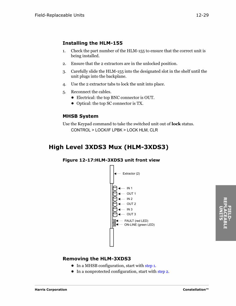
Field-Replaceable Units 12-29
FIE
LD
-R
EP
LAC
EA
BLE
U
NIT
S
Installing the HLM-155
1. Check the part number of the HLM-155 to ensure that the correct unit is being installed.
2. Ensure that the 2 extractors are in the unlocked position.
3. Carefully slide the HLM-155 into the designated slot in the shelf until the unit plugs into the backplane.
4. Use the 2 extractor tabs to lock the unit into place.
5. Reconnect the cables.• Electrical: the top BNC connector is OUT.• Optical: the top SC connector is TX.
MHSB System
Use the Keypad command to take the switched unit out of lock status.
CONTROL > LOCK/IF LPBK > LOCK HLM, CLR
High Level 3XDS3 Mux (HLM-3XDS3)
Figure 12-17:HLM-3XDS3 unit front view
Removing the HLM-3XDS3• In a MHSB configuration, start with step 1.• In a nonprotected configuration, start with step 2.
Extractor (2)
FAULT (red LED)ON-LINE (green LED)
IN 1
IN 2
IN 3
OUT 1
OUT 2
OUT 3
Harris Corporation Constellation™

12-30
In a nonprotected configuration, removing the HLM-155 is a service-affecting procedure.
1. Use the Keypad command to lock traffic on to the HLM that is not being removed. This step causes a minor alarm.
CONTROL > LOCK/IF LPBK > LOCK HLM, SET
2. Disconnect the cables by pulling the connectors straight out from the HLM-3xDS3.
3. Use the 2 extractor tabs to unlock the HLM from the shelf.
4. Carefully pull out the HLM from the shelf.
Installing the HLM-3xDS3
1. Check the part number of the HLM-3xDS3 to ensure that the correct unit is being installed.
2. Ensure that the 2 extractors are in the unlocked position.
3. Carefully slide the HLM-3xDS3 into the designated slot in the shelf until the unit plugs into the backplane.
4. Use the 2 extractor tabs to lock the unit into place.
5. Reconnect the cables. Ensure that the cables match the connector labels.
MHSB System
Use the Keypad command to take the switched unit out of lock status.
CONTROL > LOCK/IF LPBK > LOCK HLM, CLR
Constellation™ 2002 June 20

Field-Replaceable Units 12-31
FIE
LD
-R
EP
LAC
EA
BLE
U
NIT
S
Service Channel
Figure 12-18:Service Channel, front view
Removing the Service Channel
Removing the Service Channel will affect any data or VF information that the Service Channel is carrying.
1. To prevent the system from reporting a minor alarm, from the Keypad main menu, select
CONFIGURATION > SYSTEM > SVC OPTION > UNINSTALL
2. Use the 2 extractor tabs to unlock the Service Channel from the shelf.
3. Carefully pull out the Service Channel from the shelf.
Extractor (2)
FAULT (red LED)
ON-LINE (green LED)
Harris Corporation Constellation™
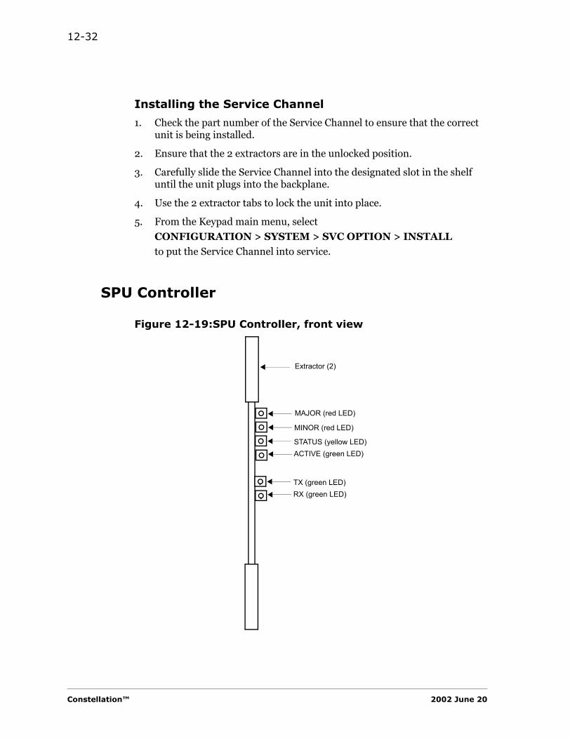
12-32
Installing the Service Channel
1. Check the part number of the Service Channel to ensure that the correct unit is being installed.
2. Ensure that the 2 extractors are in the unlocked position.
3. Carefully slide the Service Channel into the designated slot in the shelf until the unit plugs into the backplane.
4. Use the 2 extractor tabs to lock the unit into place.
5. From the Keypad main menu, select
CONFIGURATION > SYSTEM > SVC OPTION > INSTALL
to put the Service Channel into service.
SPU Controller
Figure 12-19:SPU Controller, front view
Extractor (2)
STATUS (yellow LED)ACTIVE (green LED)
MINOR (red LED)
MAJOR (red LED)
TX (green LED)RX (green LED)
Constellation™ 2002 June 20
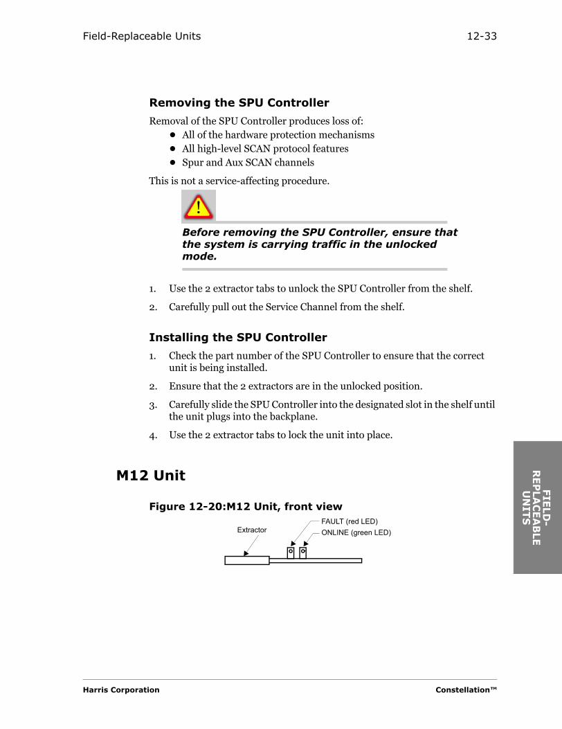
Field-Replaceable Units 12-33
FIE
LD
-R
EP
LAC
EA
BLE
U
NIT
S
Removing the SPU Controller
Removal of the SPU Controller produces loss of:• All of the hardware protection mechanisms• All high-level SCAN protocol features• Spur and Aux SCAN channels
This is not a service-affecting procedure.
Before removing the SPU Controller, ensure that the system is carrying traffic in the unlocked mode.
1. Use the 2 extractor tabs to unlock the SPU Controller from the shelf.
2. Carefully pull out the Service Channel from the shelf.
Installing the SPU Controller
1. Check the part number of the SPU Controller to ensure that the correct unit is being installed.
2. Ensure that the 2 extractors are in the unlocked position.
3. Carefully slide the SPU Controller into the designated slot in the shelf until the unit plugs into the backplane.
4. Use the 2 extractor tabs to lock the unit into place.
M12 Unit
Figure 12-20:M12 Unit, front view
ExtractorFAULT (red LED)ONLINE (green LED)
Harris Corporation Constellation™
12-34
Removing the Standby M12 Unit
1. Do this step if the Standby M12 Unit is carrying traffic.
Use the Keypad command to RELEASE STBY on the M12 Unit.
CONTROL > LOCK/IF LPBK > RELEASE STBY, EXEC
2. Use the extractor to unlock the M12 Unit from the shelf.
3. Carefully pull out the unit from the shelf.
Replacing the Standby M12 Unit
1. Ensure that the extractor of the M12 Unit is in the unlocked position.
2. Carefully slide the unit into the topmost slot of the M12 shelf until the unit plugs into the backplane.
3. Push the extractor to lock the unit into place.
Removing the M12 Unit• In a MHSB configuration, start with step 1.• In a nonprotected configuration, start with step 2.
1. Ensure that the M12 Unit to be removed is in PROTECT mode.
CONTROL > LOCK/IF LPBK > PROTECT M12, SET
2. Use the extractor to unlock the M12 Unit from the shelf.
3. Carefully pull out the unit from the shelf.
This procedure causes a hit.
Installing the M12 Unit
1. Check the part number of the M12 Unit to ensure that the correct unit is being installed.
2. Ensure that the extractor on the M12 Unit is in the unlocked position.
3. Carefully slide the unit into the designated slot in the shelf until the unit plugs into the backplane.
Constellation™ 2002 June 20

Field-Replaceable Units 12-35
FIE
LD
-R
EP
LAC
EA
BLE
U
NIT
S
This procedure causes a hit.
4. Push the extractor to lock the unit into place.
5. For a MHSB unit, use the Keypad command to release the Standby Unit.
CONTROL > LOCK/IF LPBK > RELEASE STBY, EXEC
Harris Corporation Constellation™

12-36
Constellation™ 2002 June 20

CU
STO
MER
SE
& W
AR
RA
NIN
FO
RM
ATI
C H A P T E R
13CUSTOMER SERVICE &
WARRANTY INFORMATION
Warranty and Product Support
Warranty and product support information is provided at the time of purchase with the sales invoice and other sales documents. Read the warranty information on page 13-7 for the equipment or assembly before contacting the Microwave Communications Division (MCD) Customer Service.
Ordering Parts or Spares
Harris MCD equipment is designed to be repaired by replacement at the unit level with readily available spares. For this reason, parts lists are not furnished with an order, nor are they recommended as a requirement.
Any order above the component level must be for a complete unit or for an assembly that includes one or more units. Make all inquiries for spare units to the Spare Products Support Center at the following address.
Harris Microwave Communications Division Spare Products Support Center3, Hotel de VilleDollard-des-Ormeaux, QuebecCANADA H9B 3G4
Harris Corporation Constellation™
RV
ICE
TY
O
N
13-2
Order Spare Parts Online
Spare parts can be ordered online. Sign in to the Harris Premier Customer Site:
https://premier.harris.com/microwave/
Repair and Return
General Information
Harris repairs all its manufactured products as well as coordinates repairs on vendor items which are part of its systems. Current production models have the fastest turnaround time.Discontinued items repair turnaround is subject to the availability of spares.
Repair charges and turnaround time for OEM (vendor) items are set by Harris MCD suppliers. Our close working relationships with our suppliers assure us of the best repair prices and turnaround time. Repair charges are billed at supplier’s cost plus the necessary handling fee.
Module Exchange
You may prefer to receive a replacement unit before you send your defective unit to us. Harris MCD maintains an inventory of many different modules that can be shipped to you at the fastest time possible .
Telephone NumbersCanada: 1-800-465-4654, Option 1U.S.A.: 1-800-227-8332, Option 1Worldwide: (+1) 650-594-3800, Option 1
Fax Number(+1) 514-421-3555
E-mail [email protected]
Constellation™ 2002 June 20
Customer Service & Warranty Information 13-3
CU
STO
MER
SER
& W
AR
RA
NIN
FO
RM
ATI
Emergency exchange is available, current production models have the fastest turnaround time. Emergency exchanges are billed at actual exchange prices (zero for warranty units) plus a $200.00 expedite fee per unit regardless of warranty status.
Standard module exchange is also available without expedite fee. Turnaround time is five working days.
Evaluation Fee
There is an evaluation charge per unit if no trouble is found and no repair is required.
Unrepairable Units
Equipment which has been damaged due to customer negligence, or which has had parts removed, will be repaired at the prevailing flat repair fee, or on a time-and-material basis, whichever is higher and regardless of the warranty status. Any equipment that is determined irreparable will be returned to the customer. In the case of billable orders, the standard repair charges will be waived.
Return Freight
Harris MCD prepays standard return freight back to our customers. Return freight is covered by Harris for both billable and non-billable orders.
The customer pays for shipping units to the Customer Service Location for both warranty and out-of warranty units. Special shipping requests may be subject to an additional charge.
Please pack the unit carefully using static-free, sturdy packaging to prevent damage during transit.
Harris Corporation Constellation™
VIC
E
TY
O
N
13-4
Return Material Authorization
Before sending in your equipment for repair, get Return Material Authorization (RMA) first on our Internet site at http://www.microwave.harris.com/cservice/ or contact Customer Service. This will ensure that the repairs will be done in a timely manner and eliminate any delays due to incomplete information. Please provide us with the following information when you call us.
Please provide the following information when you call (or fax):• Your name, company, telephone, and fax number• Equipment type• Part Number• Sales Order Number• Purchase Order Number (for out-of-warranty and advance exchanges)• Detailed description of the problem• Billing and shipping addresses• Any special return packing or shipping instructions• Any special customs clearance information required
Repair Telephone and Fax Numbers
U.S.A. and Canada
Repair Service Locations
Our customer service representatives will ask you to ship your defective units after the RMA is given to you in one of the following locations:
Inside CanadaWorldwide
Tel: 1-800-465-4654, Option 1(+1) 514-421-8333, Option 1
Fax: (+1) 514-421-3555
Inside the U.S.A. Tel: 1-800-227-8332, Option 1
Harris MCD Division (U.S.A.)5727 DriveSan Antonio, TX 78249, USAPhone: 1-800-227-8332 or210-561-7420Fax: 210-561-7421
Harris MCD Division (Canada)3 Hotel-de-VilleDollard-des-Ormeaux, QuebecCanada H9B 3G4Phone: 1-800-465-4654 or 514-421-8333Fax: 514-421-3555 Telex: 05-821893
Constellation™ 2002 June 20
Customer Service & Warranty Information 13-5
CU
STO
MER
SER
& W
AR
RA
NIN
FO
RM
ATI
Technical Support
Technical Assistance Center (TAC)
If you are experiencing a traffic-affecting or traffic-threatening situation, technical assistance is available 24 hours a day, 7 days a week, including holidays. If you call the Technical Assistance Center during nonbusiness hours, a Product Support Engineer will return your call within 30 minutes.
Please provide the following information when you call.• Your name, company, and telephone number• Equipment type• Detailed description of the problem
Business Hours
Normal business hours for the Technical Assistance Center:
06:30 to 17:00 (Pacific Time)Monday through Friday
Telephone Numbers
Technical support telephone numbers:
Canada 1-800-465-4654, Option 3
U.S.A. only 1-800-227-8332, Option 3(+1) 650-594-3800, Option 3
Fax Numbers
Technical support fax numbers:
Canada (+1) 514-685-4580U.S.A. (+1) 650-594-3621
Harris Corporation Constellation™
VIC
E
TY
O
N
13-6
Technical Assistance Web Site
E-mail address: [email protected]
For online support, sign in to the Harris Premier Customer Site:
https://premier.harris.com/microwave/
Mailing Address
Mailing address for the Technical Assistance Center:
Harris CorporationMicrowave Communications DivisionAttn: CRC350 Twin Dolphin DriveRedwood Shores, CA 94065-1421
Customer Training
Harris MCD offers courses in microwave, lightwave, and multiplex system operation designed to maximize product performance and minimize maintenance costs. Regular classes are held in our Montreal, Canada facilities. Special classes can be held at customer sites. Training is available for standard products. All other training requirements must be quoted by the Customer Training Department.
Telephone Numbers
Canada: 1-800-465-4654, Option 2U.S.A.: 1-800-227-8332, Option 2Worldwide: (+1) 650-594-3800, Option 2
Training Web Site
For worldwide training schedules and contact information, please visit the Harris MCD technical training Web site at
http://www.microwave.harris.com/support/training/
Constellation™ 2002 June 20
Customer Service & Warranty Information 13-7
CU
STO
MER
SER
& W
AR
RA
NIN
FO
RM
ATI
Training Centers
Canada
Harris Microwave Communications Division 3, Hotel de VilleDollard-des-Ormeaux, QuebecCANADA H9B 3G4
U.S.A.
Harris Microwave Communications Division5727 Farinon DriveSan Antonio, TX 78249
Standard Product Warranty Terms
Harris MCD warrants that each product of its own manufacture shall, at the time of delivery and for a period of 24 months thereafter, be free from defects in materials and workmanship. For such products that are installed by Harris MCD, this warranty shall extend for 18 months from date of installation, provided that the time from the date of delivery to the date of installation does not exceed 6 months. Such warranty shall not include any consumable components to which a specific manufacturer’s guarantee applies. If any Harris MCD product shall prove to be defective in materials or workmanship under normal intended usage, operation, and maintenance during the applicable warranty period as determined by Harris MCD after examination of the product claimed to be defective, then Harris MCD shall repair or replace, at Harris MCD’s sole option, such defective product, in accordance with procedures specified below, at its own expense, exclusive, however, of the cost of labor by the customer’s own employees, agents or contractors in identifying, removing or replacing the defective part(s) of the product.
In composite equipment assemblies and systems, which include equipment of such other than Harris MCD manufacture, Harris MCD’s responsibility under this warranty provision for the non-Harris MCD manufactured portion of the equipment shall be limited to the other equipment manufacturer’s standard warranty. Provided, however, that if the other manufacturer’s standard warranty period is of a shorter duration than the warranty period applicable to Harris MCD’s manufactured equipment, then Harris MCD shall extend additional coverage to such other equipment manufacturer’s warranty equal to the differential in time between the expiration of the other manufacturer’s warranty and the duration of Harris MCD’s manufactured equipment warranty applicable to such order. Harris MCD shall repair or replace, at Harris MCD’s
Harris Corporation Constellation™
VIC
E
TY
O
N

13-8
sole option, such other manufacturer’s defective part(s) within 60 days after receipt of such parts by Harris MCD in accordance with the below specified procedures, at Harris MCD’s own expense, exclusive, however, of cost of labor by the customer’s own employees, agents or contractors in identifying, removing or replacing the defective part(s) of the product.
An authorization to return products to Harris MCD under this warranty must be obtained from a Harris MCD representative prior to making shipment to Harris MCD’s plant, and all returns shall be shipped freight prepaid. Collect shipments will not be accepted, but Harris MCD will prepay return freight charges on repaired and replaced products found to be actually defective.
Liability of Harris MCD for breach of any and all warranties hereunder is expressly limited to the repair or replacement of defective products as set forth in this section, and in no event shall Harris MCD be liable for special, incidental or consequential damages by reason of any breach of warranty or defect in materials or workmanship. Harris MCD shall not be responsible for repair or replacement of products that have been subjected to neglect, accident or improper use, or that have been altered by other than authorized Harris MCD personnel.
Any warranties or conditions made herein by Harris are exclusive, made in lieu of all other warranties or conditions, express or implied (except to title) including, but not limited to, any implied warranty or condition of merchantability, any implied warranty or condition of fitness for a particular purpose, or any warranty or condition arising out of performance or custom or usage of trade. Customer acknowledges any circumstances causing any such exclusive or limited remedy to fail of its essential purpose shall not affect any Harris warranty.
Limitation of Damages
Harris’ total and maximum liability under this agreement or in connection with the subject matter of this agreement or any transaction related to this agreement, shall be limited to one-half (1/2) of the aggregate amount paid to Harris, regardless of the basis for such liability. Customer acknowledges and agrees this section shall be enforceable in the event of any claim made in connection with this agreement, including, but not limited to, any claim for failure of delivery. In no event shall Harris be liable for any punitive, special, incidental, or consequential damages, including, but not limited to lost profits, opportunities or savings or for any loss of use of, or loss of data or information of any kind, however caused or for any full or partial loss of performance of any product, even if Harris has been advised of the possibility of such damages.
Constellation™ 2002 June 20
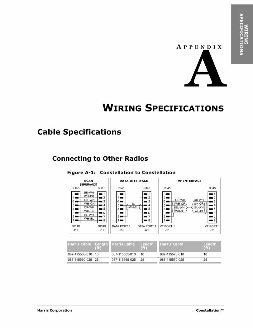
WIR
ING
S
PEC
IFIC
ATIO
NS
A P P E N D I X
AWIRING SPECIFICATIONS
Cable Specifications
Connecting to Other Radios
Figure A-1: Constellation to Constellation
Harris Cable Length(ft)
Harris Cable Length(ft)
Harris Cable Length(ft)
087-115560-010 10 087-115565-010 10 087-115570-010 10087-115560-025 25 087-115565-025 25 087-115570-025 25
1
345678
2
1
345678
2
BR-WHWH-BRGN-WHWH-GNOR-WHWH-ORBL-WHWH-BL
RJ45 RJ45
SPURJ17
SPURJ17
1
345678
2
1
345
678
2
BLWH-BL
RJ45 RJ45
DATA PORT 1J23
SCAN[SPUR/AUX]
DATA INTERFACE
DATA PORT 1J23
1
345678
2
1
345
678
2
RJ45 RJ45
VF PORT 1J21
VF INTERFACE
VF PORT 1J21
OR-WHWH-ORBL-WHWH-BL
OR-WHWH-ORBL-WHWH-BL
Harris Corporation Constellation™
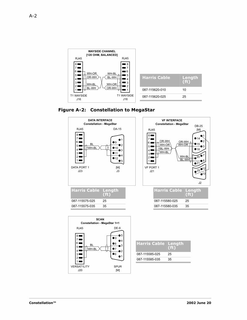
A-2
Figure A-2: Constellation to MegaStar
1
345678
21
345678
2
RJ45 RJ45
T1 WAYSIDEJ16
WAYSIDE CHANNEL[120 OHM, BALANCED]
T1 WAYSIDEJ16
WH-BLBL-WH
WH-OROR-WH
WH-BLBL-WH
WH-OROR-WH
Harris Cable Length(ft)
087-115620-010 10
087-115620-025 25
1
3
4
512
11
10
92
1
345678
2
RJ45 DA-15
DATA PORT 1J23
DATA INTERFACEConstellation - MegaStar
[M]J3
BLWH-BL
DB-25[M]
VF PORT 1J21
VF INTERFACEConstellation - MegaStar
J2
1
345678
2
RJ45
OR-WHWH-ORBL-WHWH-BL
OR-WHWH-OR
BL-WHWH-BL
1
316
15
142
1325
12
8
720
21
Harris Cable Length (ft)
Harris Cable Length (ft)
087-115575-025 25 087-115580-025 25087-115575-035 35 087-115580-035 35
1
34
5
6
7
8
9
2
1
345678
2
RJ45 DE-9
VERSAT1LITYJ20
SCANConstellation - MegaStar 1+1
SPUR[M]
BLWH-BL
Harris Cable Length (ft)
087-115585-025 25087-115585-035 35
Constellation™ 2002 June 20
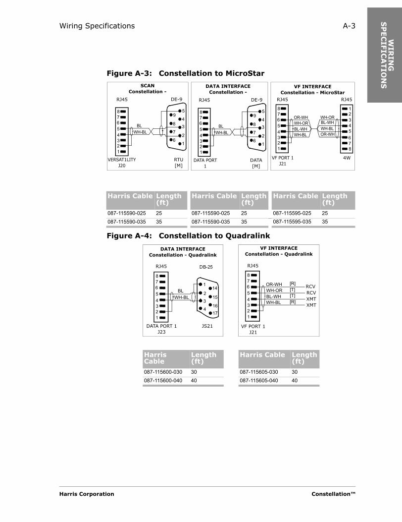
Wiring Specifications A-3
WIR
ING
S
PEC
IFIC
ATIO
NS
Figure A-3: Constellation to MicroStar
Figure A-4: Constellation to Quadralink
1
34
5
6
7
8
9
2
1
345678
2
RJ45 DE-9
VERSAT1LITYJ20
SCANConstellation -
RTU[M]
BLWH-BL
1
34
5
6
7
8
9
2
1
345678
2
RJ45 DE-9
DATA PORT 1
DATA INTERFACEConstellation -
DATA[M]
BLWH-BL
BL-WHWH-BLOR-WH
1
345678
2
1
345678
2
RJ45 RJ45
VF PORT 1J21
VF INTERFACEConstellation - MicroStar
4W
OR-WHWH-ORBL-WHWH-BL
WH-OR
Harris Cable Length (ft)
Harris Cable Length(ft)
Harris Cable Length(ft)
087-115590-025 25 087-115590-025 25 087-115595-025 25087-115590-035 35 087-115590-035 35 087-115595-035 35
Harris Cable
Length(ft)
Harris Cable Length(ft)
087-115600-030 30 087-115605-030 30087-115600-040 40 087-115605-040 40
1
345678
2
RJ45 DB-25
DATA PORT 1J23
DATA INTERFACEConstellation - Quadralink
JS21
BLWH-BL
1
316
15
142
174
1
345678
2
RJ45
VF PORT 1J21
VF INTERFACEConstellation - Quadralink
OR-WHWH-ORBL-WHWH-BL
[R]
[R]
[T][T]
RCVRCVXMTXMT
Harris Corporation Constellation™
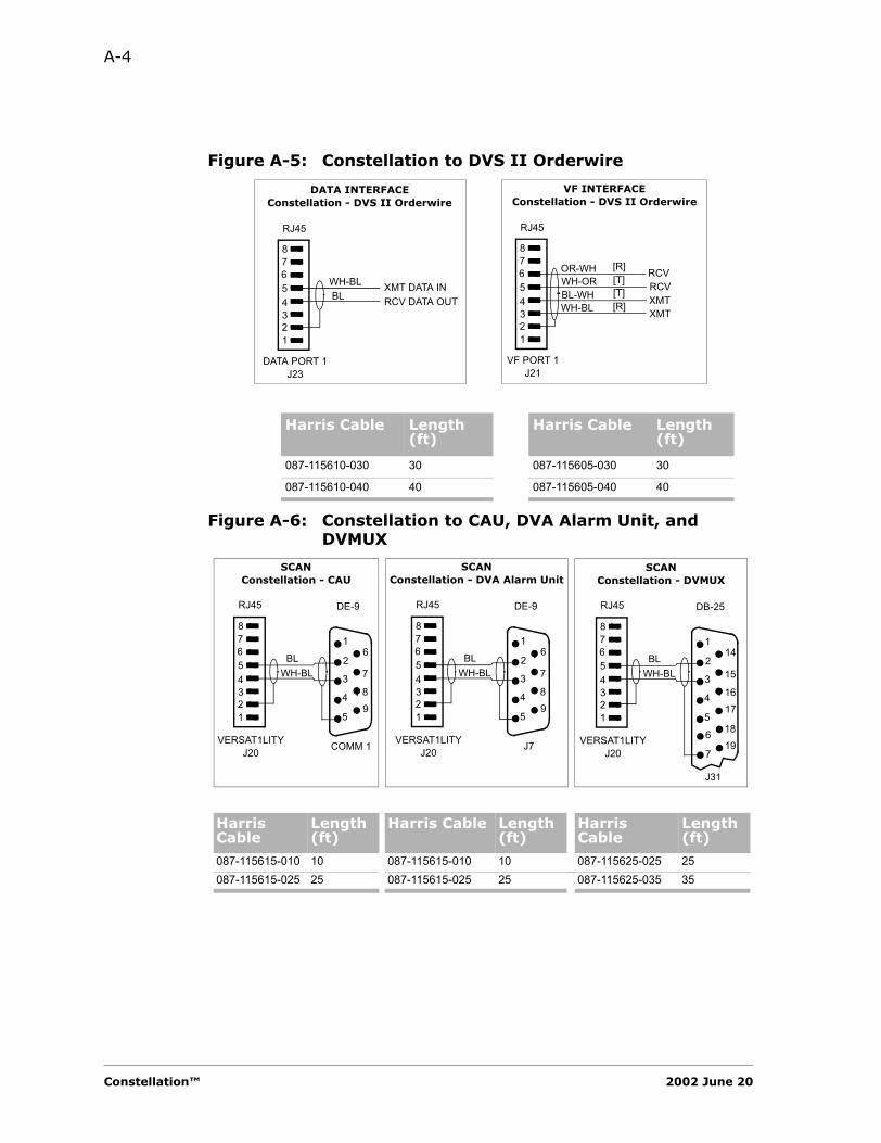
A-4
Figure A-5: Constellation to DVS II Orderwire
Figure A-6: Constellation to CAU, DVA Alarm Unit, and DVMUX
Harris Cable Length (ft)
Harris Cable Length (ft)
087-115610-030 30 087-115605-030 30
087-115610-040 40 087-115605-040 40
1
345678
2
RJ45
DATA PORT 1J23
DATA INTERFACEConstellation - DVS II Orderwire
BLWH-BL XMT DATA IN
RCV DATA OUT
1
345678
2
RJ45
VF PORT 1J21
VF INTERFACEConstellation - DVS II Orderwire
OR-WHWH-ORBL-WHWH-BL
[R]
[R]
[T][T]
RCVRCVXMTXMT
1
345678
2
RJ45 DE-9
VERSAT1LITYJ20
SCANConstellation - CAU
COMM 1
BLWH-BL
1
3
4
5
6
7
89
2
1
345678
2
RJ45 DE-9
VERSAT1LITYJ20
SCANConstellation - DVA Alarm Unit
J7
BLWH-BL
1
3
4
5
6
7
89
2
1
345678
2
RJ45 DB-25
VERSAT1LITYJ20
SCANConstellation - DVMUX
J31
BLWH-BL
1
3
4
5
14
15
1617
2
6
7
1819
Harris Cable
Length(ft)
Harris Cable Length(ft)
Harris Cable
Length(ft)
087-115615-010 10 087-115615-010 10 087-115625-025 25087-115615-025 25 087-115615-025 25 087-115625-035 35
Constellation™ 2002 June 20
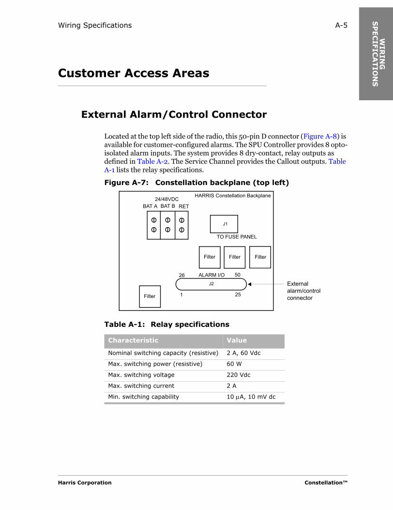
Wiring Specifications A-5
WIR
ING
S
PEC
IFIC
ATIO
NS
Customer Access Areas
External Alarm/Control Connector
Located at the top left side of the radio, this 50-pin D connector (Figure A-8) is available for customer-configured alarms. The SPU Controller provides 8 opto-isolated alarm inputs. The system provides 8 dry-contact, relay outputs as defined in Table A-2. The Service Channel provides the Callout outputs. Table A-1 lists the relay specifications.
Figure A-7: Constellation backplane (top left)
Table A-1: Relay specifications
Characteristic Value
Nominal switching capacity (resistive) 2 A, 60 Vdc
Max. switching power (resistive) 60 W
Max. switching voltage 220 Vdc
Max. switching current 2 A
Min. switching capability 10 µA, 10 mV dc
BAT A BAT B RET24/48VDC
HARRIS Constellation Backplane
TO FUSE PANEL
ALARM I/O
Filter
Filter Filter Filter
26
1 25
50
External alarm/control connector
J1
J2
Harris Corporation Constellation™
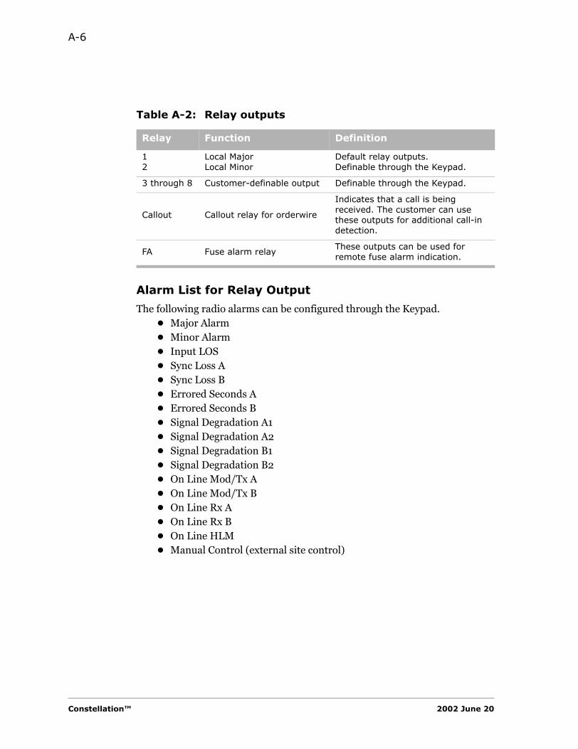
A-6
Alarm List for Relay Output
The following radio alarms can be configured through the Keypad.• Major Alarm• Minor Alarm• Input LOS• Sync Loss A• Sync Loss B• Errored Seconds A• Errored Seconds B• Signal Degradation A1• Signal Degradation A2• Signal Degradation B1• Signal Degradation B2• On Line Mod/Tx A• On Line Mod/Tx B• On Line Rx A• On Line Rx B• On Line HLM• Manual Control (external site control)
Table A-2: Relay outputs
Relay Function Definition
12
Local MajorLocal Minor
Default relay outputs.Definable through the Keypad.
3 through 8 Customer-definable output Definable through the Keypad.
Callout Callout relay for orderwire
Indicates that a call is being received. The customer can use these outputs for additional call-in detection.
FA Fuse alarm relayThese outputs can be used for remote fuse alarm indication.
Constellation™ 2002 June 20

Wiring Specifications A-7
WIR
ING
S
PEC
IFIC
ATIO
NS
Alarm I/O Pinouts
Figure A-8 shows the Alarm I/O pinouts.
Figure A-8:
Access Area for Interconnection Cabling
Located at the bottom right-hand side of the card cage, connectors are available for customer interconnection cables. Refer to Figure A-9 and Table A-3.
1
26 27 28
3
29
4
30
5
31
6
32
7
33
8
34
9
35
10
36
11
37
12
38
13
39
14
40
15 1716 18
41 4442 43
19 20
45 46 4847
21 22 23 24
49 50
252
Fuse Alarm
Callout Relay
Fan AlarmMajor Alarm
(default)
Minor Alarm
(default)
RELA
Y 1
NC
RELA
Y 1
NO
RELA
Y 1
CO
MRELA
Y 2
CO
MRELA
Y 2
NC
RELA
Y 2
NO
RELA
Y 4
NC
RELA
Y 4
NO
RELA
Y 4
CO
MRELA
Y 3
CO
MRELA
Y 3
NC
RELA
Y 3
NO
RELA
Y 5
NC
RELA
Y 5
NO
RELA
Y 5
CO
MN
CRELA
Y 7
CO
MRELA
Y 7
NO
RELA
Y 7
NC
NC
NC
NC
NC
EXT A
LARM
1G
ND
EXT A
LARM
2N
CEXT A
LARM
3FA
N A
LM R
ELA
Y N
OEXT A
LARM
4FA
N A
LM R
ELA
Y C
OM
EXT A
LARM
5FA
N A
LM R
ELA
Y N
CEXT A
LARM
6N
CEXT A
LARM
7N
CEXT A
LARM
8CALL
OU
T R
LY N
CFA
RELA
Y N
CRELA
Y 6
NC
RELA
Y 8
NC
RELA
Y 6
CO
MRELA
Y 6
NO
CALL
OU
T R
LY C
OM
CALL
OU
T R
LY N
OFA
RELA
Y C
OM
FA R
ELA
Y N
ORELA
Y 8
CO
MRELA
Y 8
NO
Harris Corporation Constellation™

A-8
Figure A-9: Constellation backplane (bottom right)
Table A-3: Serial ports
Port Signal Baud Rate (kbit/s)
Application Comments
AUX* RS-422 sync non-SCAN-compatible
Reserved for interconnecting the Constellation radios
SPUR RS-422 sync non-SCAN-compatible
CAN Factory use onlyETHERNET* 10Base-T SNMP Reserved for
StarView
Wayside Monitor
VersaT1lity VF Port VF Port Wayside Out
WaysideIn
DataPort 2
DS3 DS3 Handset Handset
Aux EthernetSpu
KeypadCan
Fan
DS1 17-32 Out
DS1 1-16 In
DS1 17-32 In
DS1 1-16 OutFSCAN
DE-9
RJ-45T1 Wayside1
E1 Wayside, SDH option only
RJ-11
26
25
26
25
25
25
26
26
1 1
11
50
50 50
50
BNC
DataPort 1
Notes:1. The wayside connection for T1 is not for 1xDS3 but only for OC-3, 3xDS3, and 2xDS3 +28xDS1.2. DS1 In = Input to the radio from the customer’s DSX.3. DS1 Out = Output from the radio to the customer’s DSX.
J16 J33 J17 J18 J31 J23 J24
J36J25 J32 J35J26 J27 J20 J21 J22 J15 J19
J28J29
J30
P15
P14
Constellation™ 2002 June 20
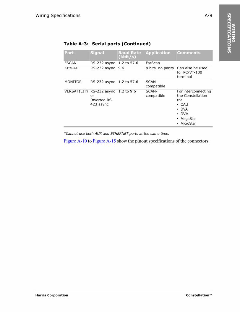
Wiring Specifications A-9
WIR
ING
S
PEC
IFIC
ATIO
NS
*Cannot use both AUX and ETHERNET ports at the same time.
Figure A-10 to Figure A-15 show the pinout specifications of the connectors.
FSCAN RS-232 async 1.2 to 57.6 FarScanKEYPAD RS-232 async 9.6 8 bits, no parity Can also be used
for PC/VT-100 terminal
MONITOR RS-232 async 1.2 to 57.6 SCAN-compatible
VERSAT1LITY RS-232 async orInverted RS-423 async
1.2 to 9.6 SCAN-compatible
For interconnecting the Constellation to:• CAU• DVA• DVM• MegaStar• MicroStar
Table A-3: Serial ports (Continued)
Port Signal Baud Rate (kbit/s)
Application Comments
Harris Corporation Constellation™

A-10
Figure A-10: RJ-45 connector pinouts
RX
DS1
WS
RR
X D
S1 W
S T
GN
DTX
DS1
WS
RTX
DS1
WS
TG
ND
NC
NC
1 3 4 5 6 7 82
NC
GN
DN
CM
ON
TXD
MO
N R
XDN
CG
ND
NC
1 3 4 5 6 7 82
RX
DAT
A SP
UR
RX
DAT
A SP
UR
RX
CLK
SPU
RR
X C
LK S
PUR
TX C
LK S
PUR
TX C
LK S
PUR
TX D
ATA
SPU
RTX
DAT
A SP
UR
1 3 4 5 6 7 82
T1 WAYSIDE, J16 MONITOR, J33 SPUR, J17
RX
DAT
A AU
XR
X D
ATA
AUX
RX
CLK
AU
XR
X C
LK A
UX
TX C
LK A
UX
TX C
LK A
UX
TX D
ATA
AUX
TX D
ATA
AUX
1 3 4 5 6 7 82
AUX, J18
RX
DAT
A EN
ETR
X D
ATA
ENET
TX D
ATA
ENET
NC
NC
TX D
ATA
ENET
NC
NC
1 3 4 5 6 7 82
ETHERNET, J31
NC
GN
DN
CTX
SC
DAT
A P1
RX
SC D
ATA
P1N
CG
ND
NC
1 3 4 5 6 7 82
DATA PORT 1, J23
NC
GN
DN
CTX
SC
DAT
A P2
RX
SC D
ATA
P2N
CG
ND
NC
1 3 4 5 6 7 82
DATA PORT 2,
NC
GN
DN
CTX
DAT
A VE
RS
RX
DAT
A VE
RS
NC
GN
DN
C
1 3 4 5 6 7 82
VERSATILITY,
TX P
ILO
T P1
GN
DTX
SC
VF
P1 R
TX S
C V
F P1
TR
X SC
VF
P1 T
RX
SC V
F P1
RG
ND
RX
PILO
T P1
1 3 4 5 6 7 82
VF PORT 1, J21
TX P
ILO
T P2
GN
DTX
SC
VF
P2 R
TX S
C V
F P2
TR
X SC
VF
P2 T
RX
SC V
F P2
RG
ND
RX
PILO
T P2
1 3 4 5 6 7 82
VF PORT 2, J22
CAN
LG
ND
NC
NC
CAN
LC
AN H
GN
DN
C
1 3 4 5 6 7 82
CAN, J15
DIS
P VC
CG
ND
NC
TX D
ATA
DIS
PR
X D
ATA
DIS
PN
CG
ND
NC
1 3 4 5 6 7 82
KEYPAD, J19
P P
P P P P
P P P P P P P
P PP
P P
P P
Constellation™ 2002 June 20
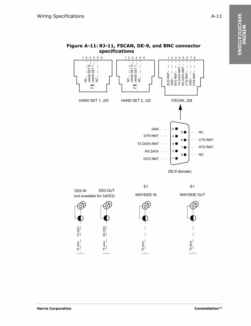
Wiring Specifications A-11
WIR
ING
S
PEC
IFIC
ATIO
NS
Figure A-11: RJ-11, FSCAN, DE-9, and BNC connector specifications
HAND SET 1, J25
NC
HAN
D S
ET R
HAN
D S
ET T
NC
1 3 4 5 62
NC
HAN
D S
ET R
HAN
D S
ET T
NC
1 3 4 5 62
HAND SET 2, J32
DC
D R
MT
GN
DR
TS R
MT
TX D
ATA
RM
TR
X D
ATA
RM
TC
TS R
MT
GN
DD
TR R
MT
1 3 4 5 6 7 82
FSCAN, J28
75 o
hmTX
DS3
75 o
hmR
X D
S3
75 o
hm
75 o
hmDS3 IN DS3 OUT
E1
WAYSIDE OUT
E1
WAYSIDE IN
DE-9 (female)
1
3
4
5
6
7
8
9
2
GND
DTR RMT
TX DATA RMT
RX DATA
DCD RMT
NC
CTS RMT
RTS RMT
NC
P P
(not available for 3xDS3)
Harris Corporation Constellation™

A-12
Figure A-12: DS1 1 to 16 In pinouts, P14 (male)
Figure A-13: DS1 1 to 16 out pinouts, J30 (female)
Figure A-14: DS1 17 to 32 out pinouts, J29 (female)
1
26 27
2
28
3
29
4
30
5
31
6
32
7
33
8
34
9
35
10
36
11
37
12
38
13
39
14
40
15 1716 18
41 4442 43
19 20
45 46 4847
21 22 23 24
49 50
25
T R T R T R T R T R T R T R T R
CKT
1
CKT
2
CKT
3
CKT
4
CKT
5
CKT
6
CKT
7
CKT
8
CKT
9
CKT
10
CKT
11
CKT
12
CKT
13
CKT
14
CKT
15
CKT
16
DS1 transmit in leads:Input to the radio from the customer’s DSX
Ground
P PP PP PP PP PP PP PP P
25
50 49 48
23
47
22
46
21
45
20
44
19
43
18
42
17
41
16
40
15
39
14
38
13
37
12
36
11 910 8
35 3234 33
7 6
31 30 2829
5 4 3 2
27 26
124
CKT
16
CKT
15
CKT
14
CKT
13
CKT
12
CKT
11
CKT
10
CKT
9
CKT
8
CKT
7
CKT
6
CKT
5
CKT
4
CKT
3
CKT
2
CKT
1
Ground
DS1 receive out leads:Output from the radio to the customer’s DSX
R T R T R T R T R T R T R T R T
P PP PP PP PP PP PP PP P
25
50 49 48
23
47
22
46
21
45
20
44
19
43
18
42
17
41
16
40
15
39
14
38
13
37
12
36
11 910 8
35 3234 33
7 6
31 30 2829
5 4 3 2
27 26
124
CKT
32
CKT
31
CKT
30
CKT
29
CKT
28
CKT
27
CKT
26
CKT
25
CKT
24
Ground
DS1 receive out leads:Output from the radio to the customer’s DSX
R T R T R T R T R T R T R T R T R T
P PP PP PP PP PP PP PP P
Constellation™ 2002 June 20
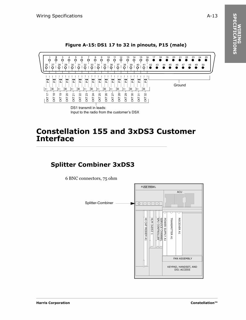
Wiring Specifications A-13
WIR
ING
S
PEC
IFIC
ATIO
NS
Figure A-15: DS1 17 to 32 in pinouts, P15 (male)
Constellation 155 and 3xDS3 Customer Interface
Splitter Combiner 3xDS3
6 BNC connectors, 75 ohm
1
26 27
2
28
3
29
4
30
5
31
6
32
7
33
8
34
9
35
10
36
11
37
12
38
13
39
14
40
15 1716 18
41 4442 43
19 20
45 46 4847
21 22 23 24
49 50
252
CKT
17
CKT
18
CKT
19
CKT
20
CKT
21
CKT
22
CKT
23
CKT
24
CKT
25
CKT
26
CKT
27
CKT
28
CKT
29
CKT
30
CKT
31
CKT
32
Ground
DS1 transmit in leads:Input to the radio from the customer’s DSX
T R T R T R T R T R T R T R T R
P PP PP PP PP PP PP PP P
TRAN
SM
ITTER A
1
RECEIV
ER A
1
SERVIC
E C
HAN
NEL
SPU
CO
NTRO
LLER
HLM
-3xD
S3 1
HI C
AP M
OD
EM
A1
ACU
FUSE PANEL
FAN ASSEMBLY
POW
ER S
UPP
LY A
1
KEYPAD, HANDSET, AND DS1 ACCESS
Splitter-Combiner
Harris Corporation Constellation™

A-14
155 Cable Interconnection Bracket
4 BNC connectors, 75 ohm
TRAN
SM
ITTER A
1
RECEIV
ER A
1
SERVIC
E C
HAN
NEL
SPU
CO
NTRO
LLER
HLM
-155 1
HI C
AP M
OD
EM
A1
ACU
FUSE PANEL
FAN ASSEMBLY
PO
WER S
UPPLY
A1
KEYPAD, HANDSET, AND DS1 ACCESS
Cableinterconnection
bracket
Constellation™ 2002 June 20
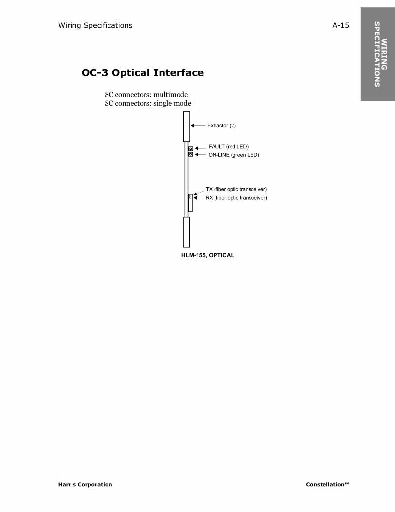
Wiring Specifications A-15
WIR
ING
S
PEC
IFIC
ATIO
NS
OC-3 Optical Interface
SC connectors: multimodeSC connectors: single mode
Extractor (2)
FAULT (red LED)ON-LINE (green LED)
TX (fiber optic transceiver)
HLM-155, OPTICAL
RX (fiber optic transceiver)
Harris Corporation Constellation™

A-16
Constellation™ 2002 June 20

KEY
PA
D M
EN
U T
REE
A P P E N D I X
BKEYPAD MENU TREE
Introduction
For software updates, refer to the Harris Premier Customer Site:
https://premier.harris.com/microwave/
Keypad or VT-100 Terminal Emulator
Introduction
The keypad is used for:• Configuration• Manual switching• Alarm monitoring
In place of the Keypad, a VT-100 terminal or a PC with a VT-100 terminal emulation software can be used to communicate with the radio.
Harris Corporation Constellation™

B-2
Cable
A cable (087-115028-001) is required to connect the Keypad to the radio’s KEYPAD (RJ-45) serial port. This cable can also be used to connect the radio to the 9-pin serial port on a VT-100 terminal or a PC with emulator.
Setting Up a PC with Emulator
The following is an example of how to set up the PC to communicate with the radio.
From the Windows-based desktop, click on the
Start button and select
ProgramsAccessoriesCommunication or Hyperterminal
In the dialog boxes that appear on the screen, type or select the correct information.
In the Flow control box, select None.
Screen Format
Serial Interface
• 9600 bits/s• 8 bits• No parity
Alphanumeric Display Size
Keypad 4 lines by 20 columns
VT-100/PC screen 20 lines by 20 columns
Constellation™ 2002 June 20
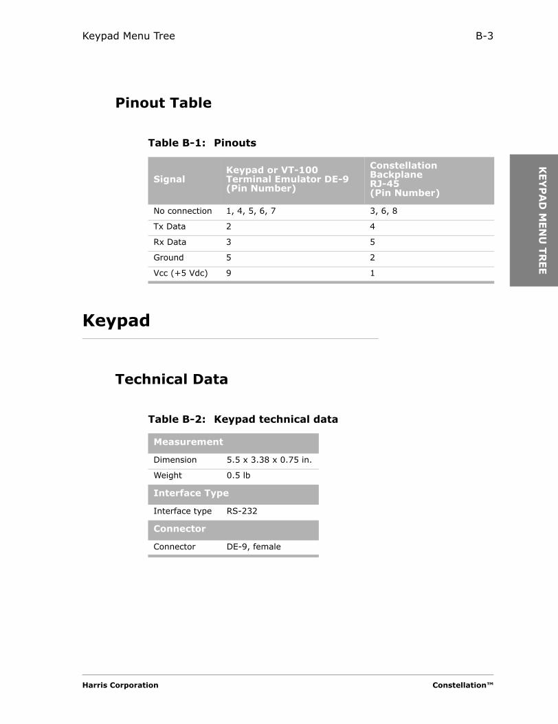
Keypad Menu Tree B-3
KEY
PA
D M
EN
U T
REE
Pinout Table
Keypad
Technical Data
Table B-1: Pinouts
SignalKeypad or VT-100 Terminal Emulator DE-9(Pin Number)
Constellation Backplane RJ-45(Pin Number)
No connection 1, 4, 5, 6, 7 3, 6, 8
Tx Data 2 4
Rx Data 3 5
Ground 5 2
Vcc (+5 Vdc) 9 1
Table B-2: Keypad technical data
Measurement
Dimension 5.5 x 3.38 x 0.75 in.
Weight 0.5 lb
Interface Type
Interface type RS-232
Connector
Connector DE-9, female
Harris Corporation Constellation™

B-4
Figure B-1: Keypad layout
Function of the Keys
F1 F2 F3 F4
ACO7 8 9 0
4 5 6
321
HOME
ENTER
?
Keypad PC Function
8 ↑ Scroll up
2 ↓ Scroll down
4 ← Page up
6 → Page down
5 . HOME
ENTER ENTER Enter a menu or carry out a command
0 to 9 0 to 9 Numeric keys
F1 PF1 Function key 1
F2 PF2 Function key 2
F3 PF3 Function key 3
F4 PF4 Function key 4
Constellation™ 2002 June 20
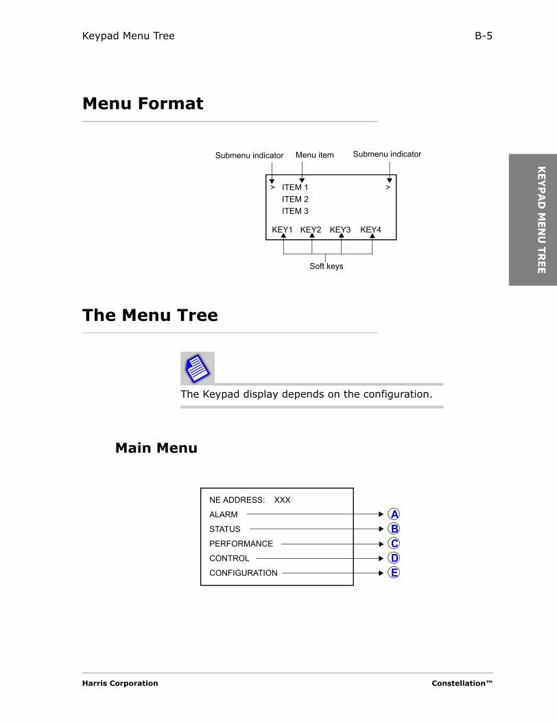
Keypad Menu Tree B-5
KEY
PA
D M
EN
U T
REE
Menu Format
The Menu Tree
The Keypad display depends on the configuration.
Main Menu
ITEM 1ITEM 2ITEM 3
KEY1 KEY2 KEY3 KEY4
> >
Soft keys
Menu item Submenu indicatorSubmenu indicator
NE ADDRESS: XXX
ALARM
STATUS
PERFORMANCE
CONTROL
CONFIGURATION
ABCDE
Harris Corporation Constellation™
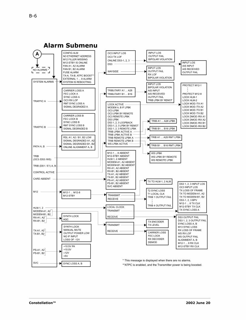
B-6
Alarm SubmenuOC3 INPUT LOSOC3 TX LOFONLINE DS3-1, 2, 3DS3
WAYSIDE
SYSTEM ALARMS
TRAFFIC A
TRAFFIC B
PATH A, B
TRIB (OC3 /DS3 /WS)
TRIB (DS1 / E1) A, B
CONTROL ACTIVE
CARD ABSENT
M12
HLM-1, 2MODEM-A1, A2MODEM-B1, B2RX-A1, A2RX-B1, B2
TX-A1, A2TX-B1, B2
PS-A1, A2PS-B1, B2
SVC
TRANSMITRECEIVE
M12-1 ... M12-8M12-STBY
CONFIG ALMNO ETHERNET ADDRESSM12 FILLER MISSINGM12-STBY IS ONLINEFAN A1, A2 ALARMFAN B1, B2 ALARMFUSE ALARMTX-A, TX-B, ATPC BOOST**EXTERNAL 1 ... 8 ALARMSYSTEM IS REBOOTING
CARRIER LOSS AFEC LOCK ASYNC LOSS AOC3 RX LOFRMT SYNC LOSS ASIGNAL DEGRADED A
TRIBUTARY A1 ... A28TRIBUTARY B1 ... B16
M12-1 ... 8 ABSENTM12-STBY ABSENTHLM-1, 2 ABSENTMODEM-A1, A2 ABSENTMODEM-B1, B2 ABSENTRX-A1, A2 ABSENTRX-B1, B2 ABSENTTX-A1, A2 ABSENTTX-B1, B2 ABSENTPS-A1, A2 ABSENTPS-B1, B2 ABSENTSVC ABSENT
LOCK ACTIVEMODEM A, B IF LPBKOC3 LPBKOC3 LPBK BY REMOTEOC3 REMOTE LPBKDS3 LPBKDS3 1, 2, 3 LOOPBACKDS3-1, 2, 3 LPBK BY REMOTDS3 1, 2, 3 REMOTE LPBKTRIB LPBK ACTIVE ATRIB LPBK ACTIVE BTRIB REMOTE LPBK ATRIB REMOTE LPBK BWS LPBK ACTIVE
SYNTH LOCKAGC
SYNTH LOCKMANUAL MUTEOUTPUT POWER LOWNO IF INPUTLOSS OF -12V
SYNC LOSS A, B
PROTECT M12-1
PROTECT M12-8LOCK HLM-1LOCK HLM-2LOCK MOD /TX A1LOCK MOD /TX A2LOCK MOD /TX B1LOCK MOD /TX B2LOCK DMOD /RX A1LOCK DMOD /RX A2LOCK DMOD /RX B1LOCK DMOD /RX B2
..
.
TRIB A1 ... A28 LPBK
TRIB A1 ... A28 RMT LPBK
TX TO HLM-1, 2 ALM
T2 SYNC LOSST1 LOCAL CLKTRIB 1 OUTPUT FAIL
TRIB 4 OUTPUT FAIL
..
.
DS3 1, 2, 3 INPUT LOSOC3 INPUT LOSTX LOSS OF FRAMETX TO MODEM-A1, A2TX TO MODEM-B1, B2DS3-1, 2, 3 BPVM12-1 ... 8 TX CLKM12-STBY TX CLKTX SYNC LOSS A
TX ENCODERTX LEVEL
CARRIER LOSSFEC LOCKRX DECODERDEMOD
RSL A1, A2 / B1, B2 LOWSIGNAL DEGRADED A1, A2SIGNAL DEGRADED B1, B2ONLINE ALIGNMENT A, B TRIB B1 ... B16 RMT LPBK
TRIB B1 ... B16 LPBK
INPUT LOSBIPOLAR VIOLATIONAIS INPUTAIS RECEIVEDOUTPUT FAILTRIB LPBK BY REMOT
A
DS3 OUTPUT FAILDS3 1, 2, 3 OUTPUT FAILSYNC LOSS A, BM13 SYNC LOSSRX LOSS OF FRAMEWS RX LOFWS OUTPUT FAILALIGNMENT A, BM12-1 ... 8 RX CLKM12-STBY RX CLK+10.5V PA
+10.5V±12V+5V
TRANSMIT
RECEIVE
LOCAL CLOCKTRANSMIT
RECEIVE
* This message is displayed when there are no alarms.**ATPC is enabled, and the Transmitter power is being boosted.
NO ALARMS *
CARRIER LOSS BFEC LOCK BSYNC LOSS BRMT SYNC LOSS BSIGNAL DEGRADED B
INPUT LOSOUTPUT FAILBIPOLAR VIOLATION
INPUT LOSAIS INPUTAIS RECEIVEDOUTPUT FAIL
INPUT LOSOUTPUT FAILRX LOFBIPOLAR VIOLATION
WS LPBKWS LPBK BY REMOTEWS REMOTE LPBK
Constellation™ 2002 June 20

Keypad Menu Tree B-7
KEY
PA
D M
EN
U T
REE
Status Submenu
The values in the Status Submenu cannot be modified..
ON LINE EQUIPMENT
SYSTEM
RELAYS
INVENTORY
PROTECTED M12 X 1/.../8/NONEON LINE HLM X 1/2ON LINE MOD/TX A X 1/2ON LINE MOD/TX B X 1/2ON LINE DEMOD/RX A X 1/2ON LINE DEMOD/RX B X 1/2
MAX CAPACITY XXXXXX 8xDS1/16xDS1/28xDS1/24xE1/1xDS3/3xDS3/155MBIT
3DS3 CAPACITY USE:XXXXXXXXXXXXXXXXXX T3-1, T3-2, T3-3/
T2 ADM, T3-2, T3-3/T3-1, T2 ADM, T3-3/T3-1, T3-2, T2 ADM/28 T1, T3-2, T3-3/T3-1, 28 T1, T3-3/T3-1, T3-2, 28 T1
USED CAPACITY XXXXXXX 4xTRIB/8xTRIB/12xTRIB/16xTRIB/20xTRIB/24xTRIB/28xTRIB
MODE XXXXXXXX TERMINAL/REPEATERTRIB I/F XXXXXXXXXX ELECTRICAL/OPTICALTX A1, A2 PWR XXXdBmTX B1,B2 PWR XXXdBmRSL A1, A2 XXXdBmRSL B1, B2 XXXdBmTX A1, A2 TEMP* XXX CTX B1, B2 TEMP* XXX CRCS SW A1 TO A2 XXX SET/CLRRCS SW A2 TO A1 XXX SET/CLRRCS SW B1 TO B2 XXX SET/CLRRCS SW B2 TO B1 XXX SET/CLR
CONTROLLERM12-1
M12-8M12-STBYHLM-1, 2MODEM-A1, A2MODEM-B1, B2TX-A1, A2 / B1, B2RX-A1, A2 / B1, B2PS-A1, A2 / B1, B2SVC
..
.
S/W VER XXXXBOOT VER XXXXPN XXX-XXXXXX-XXXSN XXXXXXXXREVISION XXDATE XX-XX-XXXX
S/W VER XXXXPN XXX-XXXXXX-XXXSN XXXXXXXXREVISION XXDATE XX-XX-XXXX
RELAY 1 ... 8 XXX SET/CLR
B
* Temperature reading on the Keypad will be typically 45ºC to 55ºC at ambient temperature of 25ºC.
Harris Corporation Constellation™
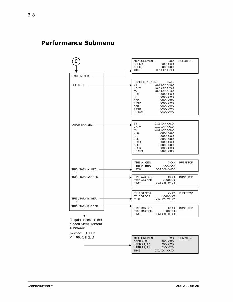
B-8
Performance Submenu
SYSTEM BER
ERR SEC
LATCH ERR SEC
TRIBUTARY A1 BER
TRIBUTARY A28 BER
TRIBUTARY B1 BER
TRIBUTARY B16 BER
..
.
..
.
MEASUREMENT XXX RUN/STOPCBER A XXXXXXXCBER B XXXXXXXTIME XXd XXh XX:XX
TRIB A1 GEN XXXX RUN/STOPTRIB A1 BER XXXXXXXTIME XXd XXh XX:XX
TRIB A28 GEN XXXX RUN/STOPTRIB A28 BER XXXXXXXTIME XXd XXh XX:XX
TRIB B1 GEN XXXX RUN/STOPTRIB B1 BER XXXXXXXTIME XXd XXh XX:XX
TRIB B16 GEN XXXX RUN/STOPTRIB B16 BER XXXXXXXTIME XXd XXh XX:XX
MEASUREMENT XXX RUN/STOPCBER A, B XXXXXXXUBER A1, A2 XXXXXXXUBER B1, B2 XXXXXXXTIME XXd XXh XX:XX
To gain access to the hidden Measurement submenu:Keypad: F1 + F3VT100: CTRL B
C
RESET STATISTIC EXECET XXd XXh XX:XXUNAV XXd XXh XX:XXAV XXd XXh XX:XXEFS XXXXXXXXES XXXXXXXXSES XXXXXXXXEFSR XXXXXXXXESR XXXXXXXXSESR XXXXXXXXUNAVR XXXXXXXX
ET XXd XXh XX:XXUNAV XXd XXh XX:XXAV XXd XXh XX:XXEFS XXXXXXXXES XXXXXXXXSES XXXXXXXXEFSR XXXXXXXXESR XXXXXXXXSESR XXXXXXXXUNAVR XXXXXXXX
Constellation™ 2002 June 20
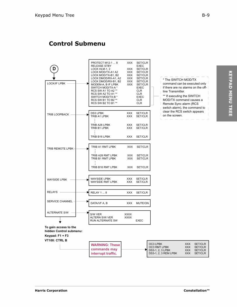
Keypad Menu Tree B-9
KEY
PA
D M
EN
U T
REE
Control Submenu
LOCK/IF LPBK
TRIB LOOPBACK
TRIB REMOTE LPBK
WAYSIDE LPBK
RELAYS
SERVICE CHANNEL
ALTERNATE S/W
DATA/VF A, B XXX MUTE/ON
S/W VER XXXXALTERN S/W VER XXXXRUN ALTERNATE SW EXEC
PROTECT M12-1 ... 8 XXX SET/CLRRELEASE STBY EXECLOCK HLM-1, 2 XXX SET/CLRLOCK MOD/TX-A1 A2 XXX SET/CLRLOCK MOD/TX-B1, B2 XXX SET/CLRLOCK DMOD/RX-A1, A2 XXX SET/CLRLOCK DMOD/RX-B1, B2 XXX SET/CLRMODEM-A, B IF LPBK XXX SET/CLRSWITCH MOD/TX-A * EXECRCS SW A1 TO A2 ** CLRRCS SW A2 TO A1 ** CLRSWITCH MOD/TX-B * EXECRCS SW B1 TO B2 ** CLRRCS SW B2 TO B1 ** CLR
TRIB A1 RMT LPBK XXX SET/CLR
TRIB A28 RMT LPBK XXX SET/CLRTRIB B1 RMT LPBK XXX SET/CLR
TRIB B16 RMT LPBK XXX SET/CLR
..
.
..
.
RELAY 1 ... 8 XXX SET/CLR
DS3 LPBK XXX SET/CLRTRIB A1 LPBK XXX SET/CLR
TRIB A28 LPBK XXX SET/CLRTRIB B1 LPBK XXX SET/CLR
TRIB B16 LPBK XXX SET/CLR
..
.
..
.
D
* The SWITCH MOD/TX command can be executed only if there are no alarms on the off-line Transmitter.** If executing the SWITCH MOD/TX command causes a Remote Sync alarm (RCS switch alarm), the command to clear the RCS switch appears on the screen.
WAYSIDE LPBK XXX SET/CLRWAYSIDE RMT LPBK XXX SET/CLR
To gain access to the hidden Control submenu:Keypad: F1 + F3VT100: CTRL B
OC3 LPBK XXX SET/CLROC3 RMT LPBK XXX SET/CLRDS3-1, 2, 3 LPBK XXX SET/CLRDS3-1, 2, 3 REM LPBK XXX SET/CLR
WARNING: These commands may interrupt traffic.
Harris Corporation Constellation™
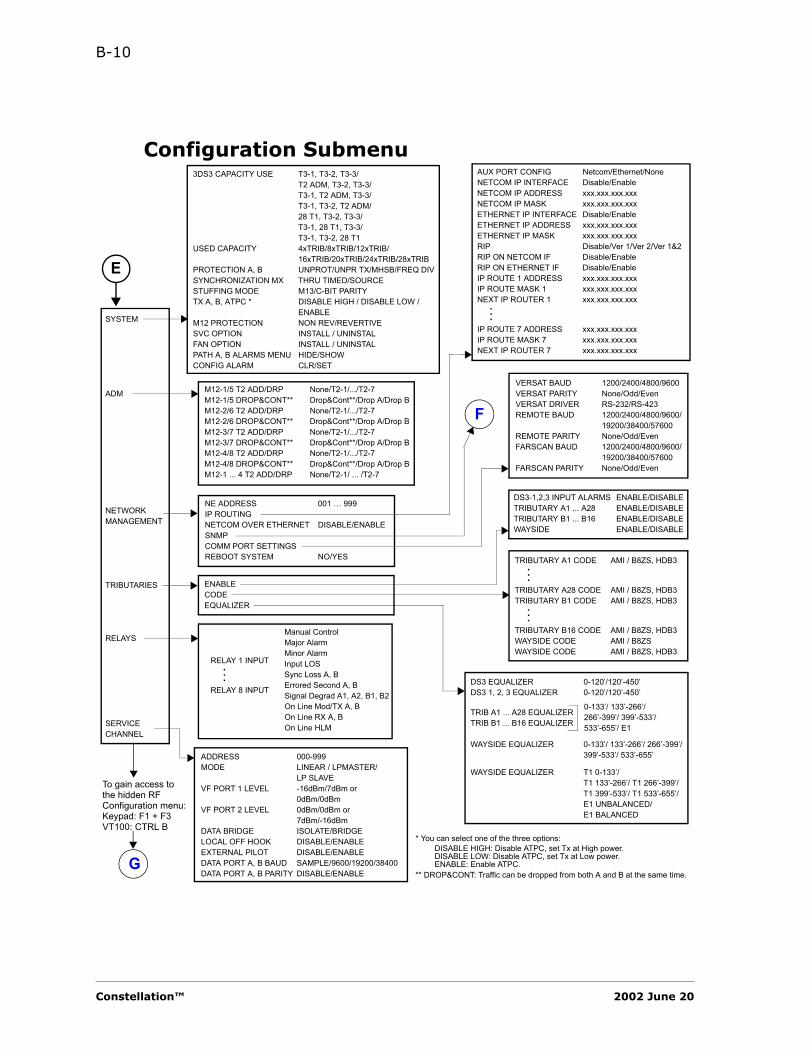
B-10
Configuration Submenu
M12-1/5 T2 ADD/DRP None/T2-1/.../T2-7M12-1/5 DROP&CONT** Drop&Cont**/Drop A/Drop BM12-2/6 T2 ADD/DRP None/T2-1/.../T2-7M12-2/6 DROP&CONT** Drop&Cont**/Drop A/Drop BM12-3/7 T2 ADD/DRP None/T2-1/.../T2-7M12-3/7 DROP&CONT** Drop&Cont**/Drop A/Drop BM12-4/8 T2 ADD/DRP None/T2-1/.../T2-7M12-4/8 DROP&CONT** Drop&Cont**/Drop A/Drop BM12-1 ... 4 T2 ADD/DRP None/T2-1/ ... /T2-7
SYSTEM
ADM
NETWORK MANAGEMENT
TRIBUTARIES
RELAYS
SERVICECHANNEL
3DS3 CAPACITY USE T3-1, T3-2, T3-3/T2 ADM, T3-2, T3-3/T3-1, T2 ADM, T3-3/T3-1, T3-2, T2 ADM/28 T1, T3-2, T3-3/T3-1, 28 T1, T3-3/T3-1, T3-2, 28 T1
USED CAPACITY 4xTRIB/8xTRIB/12xTRIB/16xTRIB/20xTRIB/24xTRIB/28xTRIB
PROTECTION A, B UNPROT/UNPR TX/MHSB/FREQ DIVSYNCHRONIZATION MX THRU TIMED/SOURCESTUFFING MODE M13/C-BIT PARITYTX A, B, ATPC * DISABLE HIGH / DISABLE LOW /
ENABLEM12 PROTECTION NON REV/REVERTIVESVC OPTION INSTALL / UNINSTALFAN OPTION INSTALL / UNINSTALPATH A, B ALARMS MENU HIDE/SHOWCONFIG ALARM CLR/SET
ENABLECODEEQUALIZER
DS3-1,2,3 INPUT ALARMS ENABLE/DISABLETRIBUTARY A1 ... A28 ENABLE/DISABLETRIBUTARY B1 ... B16 ENABLE/DISABLEWAYSIDE ENABLE/DISABLE
TRIBUTARY A1 CODE AMI / B8ZS, HDB3
TRIBUTARY A28 CODE AMI / B8ZS, HDB3TRIBUTARY B1 CODE AMI / B8ZS, HDB3
TRIBUTARY B16 CODE AMI / B8ZS, HDB3WAYSIDE CODE AMI / B8ZSWAYSIDE CODE AMI / B8ZS, HDB3
..
.
..
.
DS3 EQUALIZER 0-120’/120’-450’DS3 1, 2, 3 EQUALIZER 0-120’/120’-450’
TRIB A1 ... A28 EQUALIZERTRIB B1 ... B16 EQUALIZER
WAYSIDE EQUALIZER 0-133’/ 133’-266’/ 266’-399’/ 399’-533’/ 533’-655’
WAYSIDE EQUALIZER T1 0-133’/T1 133’-266’/ T1 266’-399’/ T1 399’-533’/ T1 533’-655’/E1 UNBALANCED/E1 BALANCED
To gain access to the hidden RF Configuration menu:Keypad: F1 + F3VT100: CTRL B
NE ADDRESS 001 … 999IP ROUTINGNETCOM OVER ETHERNET DISABLE/ENABLESNMPCOMM PORT SETTINGSREBOOT SYSTEM NO/YES
AUX PORT CONFIG Netcom/Ethernet/NoneNETCOM IP INTERFACE Disable/EnableNETCOM IP ADDRESS xxx.xxx.xxx.xxxNETCOM IP MASK xxx.xxx.xxx.xxxETHERNET IP INTERFACE Disable/EnableETHERNET IP ADDRESS xxx.xxx.xxx.xxxETHERNET IP MASK xxx.xxx.xxx.xxxRIP Disable/Ver 1/Ver 2/Ver 1&2RIP ON NETCOM IF Disable/EnableRIP ON ETHERNET IF Disable/EnableIP ROUTE 1 ADDRESS xxx.xxx.xxx.xxxIP ROUTE MASK 1 xxx.xxx.xxx.xxxNEXT IP ROUTER 1 xxx.xxx.xxx.xxx
IP ROUTE 7 ADDRESS xxx.xxx.xxx.xxxIP ROUTE MASK 7 xxx.xxx.xxx.xxxNEXT IP ROUTER 7 xxx.xxx.xxx.xxx
..
.
VERSAT BAUD 1200/2400/4800/9600VERSAT PARITY None/Odd/EvenVERSAT DRIVER RS-232/RS-423REMOTE BAUD 1200/2400/4800/9600/
19200/38400/57600REMOTE PARITY None/Odd/EvenFARSCAN BAUD 1200/2400/4800/9600/
19200/38400/57600FARSCAN PARITY None/Odd/Even
ADDRESS 000-999MODE LINEAR / LPMASTER/
LP SLAVEVF PORT 1 LEVEL -16dBm/7dBm or
0dBm/0dBmVF PORT 2 LEVEL 0dBm/0dBm or
7dBm/-16dBmDATA BRIDGE ISOLATE/BRIDGELOCAL OFF HOOK DISABLE/ENABLEEXTERNAL PILOT DISABLE/ENABLEDATA PORT A, B BAUD SAMPLE/9600/19200/38400DATA PORT A, B PARITY DISABLE/ENABLE
* You can select one of the three options:DISABLE HIGH: Disable ATPC, set Tx at High power.DISABLE LOW: Disable ATPC, set Tx at Low power.ENABLE: Enable ATPC.
** DROP&CONT: Traffic can be dropped from both A and B at the same time.
RELAY 1 INPUT
RELAY 8 INPUT
..
.
E
G
Manual ControlMajor AlarmMinor AlarmInput LOSSync Loss A, BErrored Second A, BSignal Degrad A1, A2, B1, B2On Line Mod/TX A, BOn Line RX A, BOn Line HLM
F
0-133’/ 133’-266’/ 266’-399’/ 399’-533’/ 533’-655’/ E1
Constellation™ 2002 June 20

Keypad Menu Tree B-11
KEY
PA
D M
EN
U T
REE
SNMP Submenu
MANAGER 1 IP ADDR xxx.xxx.xxx.xxx
MANAGER 10 IP ADDR xxx.xxx.xxx.xxx
TRAP DEST 1 IP ADDR xxx.xxx.xxx.xxx
TRAP DEST 10 IP ADDR xxx.xxx.xxx.xxx
TRAP TIMEOUT (SEC) xxxTRAP REPEAT xxxTRAP COMMUNITY Constellation
DISABLE TRAPS
..
.
..
.
F
ALL TRAPS Disable All/CFG IndividuallySYSTEM ALARM TRAPS Enable/DisableCONF ALM TRAP Enable/DisableFUSE TRAP Enable/DisableEXTERNAL ALM TRAP Enable/DisableABSENT TRAP Enable/DisableMANAGED TRAP Enable/DisablePS ALM TRAP Enable/DisableTX HIGH PWR ALM TRAP Enable/DisableTX MAN MUTE ALM TRAP Enable/DisableTX SYNTH TRAP Enable/DisableTX ALC TRAP Enable/DisableTX FAN ALM TRAP Enable/DisableRX RSL ALM TRAP Enable/DisableRX SYNTH TRAP Enable/DisableRX AGC ALM TRAP Enable/DisableONLINE MDM CARRIER Enable/DisableONLINE MDM FEC LOCK Enable/DisableMODEM TX TRAP Enable/DisableMODEM RX TRAP Enable/DisableMODEM RX EQM TRAP Enable/DisableMODEM UBER ALM TRAP Enable/DisableHLM RX TRAP Enable/DisableHLM SYNC TRAP Enable/DisableHLM RX LOF TRAP Enable/DisableHLM RX AIS TRAP Enable/DisableHLM DS3 OUT TRAP Enable/DisableHLM ALIGN TRAP Enable/DisableHLM TX TRAP Enable/DisableHLM TX LOF TRAP Enable/DisableHLM LOS TRAP Enable/DisableDS3 LOS ALM TRAP Enable/DisableDS3 BPV ALM TRAP Enable/DisableM12 MISSING TRAP Enable/DisableM12 STBY ONLINE TRAP Enable/DisableM12 RX TRAP Enable/DisableM12 TX TRAP Enable/DisableM12 SYNC TRAP Enable/DisableOUT ALM TRAP Enable/DisableLOS ALM TRAP Enable/DisableBPV ALM TRAP Enable/DisableAIS INPUT ALM TRAP Enable/DisableRX AIS ALM TRAP Enable/DisableRX REM LPBK ALM Enable/DisableWAYSIDE ALM TRAP Enable/DisableSVC SYNC TRAP Enable/Disable
Harris Corporation Constellation™
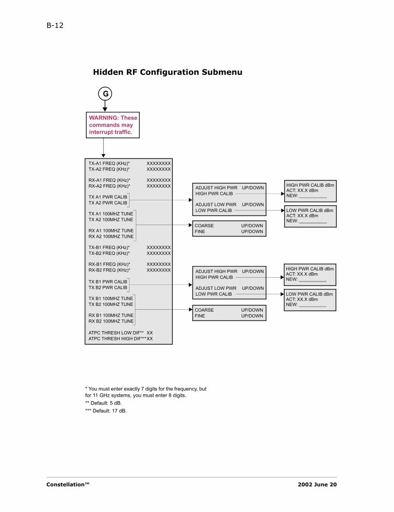
B-12
Hidden RF Configuration Submenu
TX-A1 FREQ (KHz)* XXXXXXXXTX-A2 FREQ (KHz)* XXXXXXXX
RX-A1 FREQ (KHz)* XXXXXXXXRX-A2 FREQ (KHz)* XXXXXXXX
TX A1 PWR CALIBTX A2 PWR CALIB
TX A1 100MHZ TUNETX A2 100MHZ TUNE
RX A1 100MHZ TUNERX A2 100MHZ TUNE
TX-B1 FREQ (KHz)* XXXXXXXXTX-B2 FREQ (KHz)* XXXXXXXX
RX-B1 FREQ (KHz)* XXXXXXXXRX-B2 FREQ (KHz)* XXXXXXXX
TX B1 PWR CALIBTX B2 PWR CALIB
TX B1 100MHZ TUNETX B2 100MHZ TUNE
RX B1 100MHZ TUNERX B2 100MHZ TUNE
ATPC THRESH LOW DIF** XXATPC THRESH HIGH DIF***XX
COARSE UP/DOWNFINE UP/DOWN
ADJUST HIGH PWR UP/DOWNHIGH PWR CALIB
ADJUST LOW PWR UP/DOWNLOW PWR CALIB
WARNING: These commands may interrupt traffic.
HIGH PWR CALIB dBmACT: XX.X dBmNEW: ___________
LOW PWR CALIB dBmACT: XX.X dBmNEW: ___________
COARSE UP/DOWNFINE UP/DOWN
ADJUST HIGH PWR UP/DOWNHIGH PWR CALIB
ADJUST LOW PWR UP/DOWNLOW PWR CALIB
HIGH PWR CALIB dBmACT: XX.X dBmNEW: ___________
LOW PWR CALIB dBmACT: XX.X dBmNEW: ___________
G
* You must enter exactly 7 digits for the frequency, but for 11 GHz systems, you must enter 8 digits.** Default: 5 dB.*** Default: 17 dB.
Constellation™ 2002 June 20
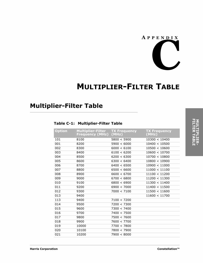
MU
LTIP
LIER
-FILT
ER
TA
BLE
A P P E N D I X
CMULTIPLIER-FILTER TABLE
Multiplier-Filter Table
Table C-1: Multiplier-Filter Table
Option Multiplier-Filter Frequency (MHz)
TX Frequency(MHz)
TX Frequency(MHz)
101 8100 5800 < 5900 10300 < 10400001 8200 5900 < 6000 10400 < 10500002 8300 6000 < 6100 10500 < 10600003 8400 6100 < 6200 10600 < 10700004 8500 6200 < 6300 10700 < 10800005 8600 6300 < 6400 10800 < 10900006 8700 6400 < 6500 10900 < 11000007 8800 6500 < 6600 11000 < 11100008 8900 6600 < 6700 11100 < 11200009 9000 6700 < 6800 11200 < 11300010 9100 6800 < 6900 11300 < 11400011 9200 6900 < 7000 11400 < 11500012 9300 7000 < 7100 11500 < 11600013 9400 11600 < 11700113 9400 7100 < 7200014 9500 7200 < 7300015 9600 7300 < 7400016 9700 7400 < 7500017 9800 7500 < 7600018 9900 7600 < 7700019 10000 7700 < 7800020 10100 7800 < 7900021 10200 7900 < 8000
Harris Corporation Constellation™

C-2
LO MON Frequency Calculation
Calculate the LO MON frequency as follows.
1. First, find the difference between the TX Frequency and the Multiplier Frequency.
2. Then subtract 140 MHz from the difference to arrive at the LO MON frequency.
The LO MON frequency is always between 2060 and 2160 MHz.
022 10300 8000 < 8100023 10400 8100 < 8200024 10500 8200 < 8300025 10600 8300 < 8400026 10700 8400 < 8500
Table C-1: Multiplier-Filter Table (Continued)
Option Multiplier-Filter Frequency (MHz)
TX Frequency(MHz)
TX Frequency(MHz)
7/8 GHz Example: 11 GHz Example:Multiplier Frequency = 9800.000 MHz Transmit Frequency = 11192.500 MHz
Transmit Frequency = 7561.500 MHz Multiplier Frequency = 8900.000 MHz
Difference = 2238.500 MHz Difference = 2292.500 MHz
Subtract −140.000 MHz Subtract −140.000 MHz
LO MON Frequency = 2098.500 MHz LO MON Frequency = 2152.500 MHz
Constellation™ 2002 June 20
SER
VIC
E C
HA
NN
EL
A P P E N D I X
DSERVICE CHANNEL
Loop System
The Constellation Service Channel is capable of operating as a repeater or a terminal in a linear system or providing protection in a single or multiple loop system.
The Service Channel can be set up in the following ways.• Linear or loop system• Master or slave (for loop system only)• External pilot on or off (for slave loop system only)• Local off-hook, enable or disable
The Service Channel in a loop system must always have one break in the loop to prevent the data from propagating in a continuous loop. This break is always done at the Master site in the A direction. Whenever a system failure occurs that causes another break in the loop, the Master site must know about this failure so it can remove its break. The pilot signal communicates this information to the Master site. As long as there is only one break in the loop, all system sites will have communication. All Service Channel loop systems, even in multitude loops, work on this principle.
Harris Corporation Constellation™
D-2
Loop System Configurations
Single Loop System Using Repeaters
Single Loop System Using Repeaters (Figure D-1) shows the Service Channel’s settings. Note that the Service Channel setting does not always correspond to the radio or multiplexer system settings. However, in this case, it does.
To explain how this system works, a pilot A signal is generated from the Master Repeater A site. The pilot signal propagates through three other Slave Repeater Service Channels where it is received back at the Master Repeater B. The pilot is looped and sent back to Master Repeater A where it is detected.
When the pilot is detected, the data is prevented from being transmitted or received at Master Repeater A. This process causes a break in the loop which is necessary under normal conditions.
However, if the pilot is not detected because of a system failure, a second break in the loop is created. The data at Master Repeater A is now allowed to transmit and receive by removing the original break.
When a sync alarm occurs in one direction, the Service Channel prevents data from being transmitted or received in that direction.
Constellation™ 2002 June 20
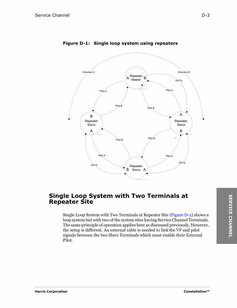
Service Channel D-3
SER
VIC
E C
HA
NN
EL
Figure D-1: Single loop system using repeaters
Single Loop System with Two Terminals at Repeater Site
Single Loop System with Two Terminals at Repeater Site (Figure D-2) shows a loop system but with two of the system sites having Service Channel Terminals. The same principle of operation applies here as discussed previously. However, the setup is different. An external cable is needed to link the VF and pilot signals between the two Slave Terminals which must enable their External Pilot.
RepeaterMaster
RepeaterSlave
RepeaterSlave
RepeaterSlave
Pilot A
Pilot A Pilot A
Pilot A
Pilot B
Pilot BPilot B
Pilot B
DATA
DATADATA
Direction A Direction B
A
A
A
AB
B
B
B
Harris Corporation Constellation™

D-4
Figure D-2: Single loop system with two terminals at repeater site
Multiple Loop System, a Loop within a Loop
Multiple Loop System, a Loop within a Loop (Figure D-3) shows a loop system within a loop system. The inner loop is the same loop as discussed in the first loop system (Single Loop System Using Repeaters), and its operation is identical. The second loop is made up of a Master Terminal and three Slave Terminals and looks like a linear system that is connected to the main loop.
The outer loop operates as follows. The Master Terminal generates a pilot so that it can propagate through two Slave Terminals and to the third Slave Terminal where it is looped back and returned to the Master Terminal. If the pilot is detected, the Master Terminal does not transmit or receive any data.
The cables that connect the VF and Data between the Master Terminal and the Slave Repeater allow communication between the two systems. Any data that is received at the third Slave Terminal on the outer loop is passed through the cables that are connected to the Slave Repeater of the inner loop.
TerminalSlave
RepeaterSlave
RepeaterSlave
Pilot A
Pilot APilot A
Pilot A
Pilot A
Pilot BPilot A
Pilot B
TerminalMaster
Data
VF
DATA
DATA
DATA
Direction A Direction B
TerminalSlave
TerminalSlave
Data
VFExternal
Pilots
AA
A
B A
B
A A
Constellation™ 2002 June 20

Service Channel D-5
SER
VIC
E C
HA
NN
EL
If the pilot is not detected at the Master Terminal because of a break in the outer loop, data is allowed to transmit and be received at the Master Terminal. Note that the two Slave Terminals of the outer loop must have the External Pilot option enabled to allow the pilots to propagate between them.
Figure D-3: Multiple loop system, a loop within a loop
Two Separate Loop Systems
Example A
Two Separate Loop Systems, Example A (Figure D-4) shows two loop systems connected together by two cables. The two loop systems operate independently and identical as previously discussed. Note that both Slave Terminals in Loop 1 must have the External Pilots enabled.
RepeaterMaster
RepeaterSlave
RepeaterSlave
RepeaterSlave
Pilot A
Pilot A Pilot A
Pilot A
Pilot B
Pilot BPilot B
Pilot B
DATA
DATADATA
Direction A Direction B
TerminalMaster
TerminalSlave
TerminalSlave
TerminalSlave
Data
VFExternal
Pilots
VF
Data
VF
Data
Pilot A
Pilot A
DATAPilot A
Pilot A
DATA
A A
AA A
B A
B
AB
A B
Harris Corporation Constellation™
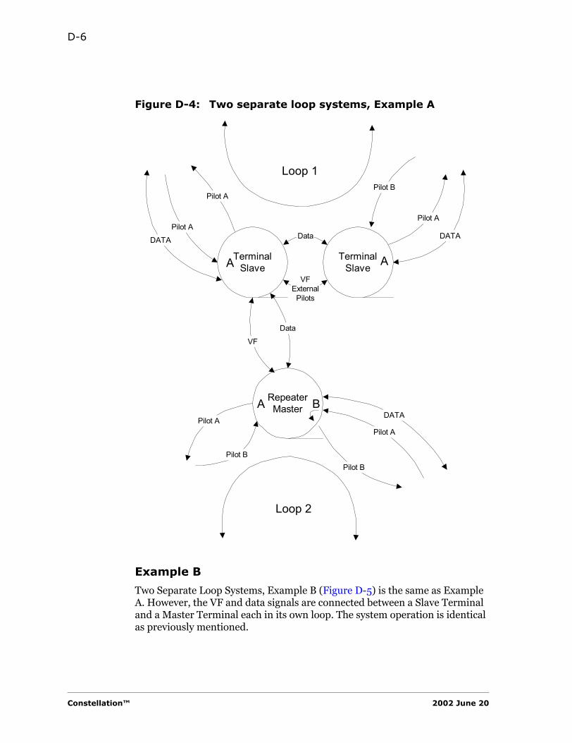
D-6
Figure D-4: Two separate loop systems, Example A
Example B
Two Separate Loop Systems, Example B (Figure D-5) is the same as Example A. However, the VF and data signals are connected between a Slave Terminal and a Master Terminal each in its own loop. The system operation is identical as previously mentioned.
Pilot APilot A
Pilot BPilot A
DATADATA
TerminalSlave
TerminalSlave
Data
VFExternal
Pilots
RepeaterMaster
VF
Data
Pilot A
Pilot B
DATA
Pilot A
Pilot B
A A
A B
Loop 1
Loop 2
Constellation™ 2002 June 20
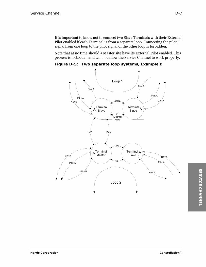
Service Channel D-7
SER
VIC
E C
HA
NN
EL
It is important to know not to connect two Slave Terminals with their External Pilot enabled if each Terminal is from a separate loop. Connecting the pilot signal from one loop to the pilot signal of the other loop is forbidden.
Note that at no time should a Master site have its External Pilot enabled. This process is forbidden and will not allow the Service Channel to work properly.
Figure D-5: Two separate loop systems, Example B
Pilot APilot A
Pilot BPilot A
DATADATA
TerminalSlave
TerminalSlave
Data
VFExternalPilots
TerminalSlave
VF Data
Pilot A
Pilot B
DATA
Pilot A
Pilot A
TerminalMaster
Data
VF
DATA
A A
Loop 1
A A
Loop 2
Harris Corporation Constellation™
D-8
Customer Setup
Set the Service Channel for Loop Master or Loop Slave. There can be only one Master system in a Loop System, but there must be at least one. Each loop in a multiple Loop System must have a Master.
Enable External Pilot for back-to-back Loop Slave terminal so that the pilot signal passes between two terminals.
Enable Local Off-Hook if an external VF signal is applied to a VF port or if the repeater timing is set to Source in a loop system.
Constellation™ 2002 June 20
HA
RR
IS P
AN
UM
BER
IS
YS
TEM
A P P E N D I X
EHARRIS PART-NUMBERING
SYSTEM
Introduction
Whenever ordering a spare or replacement unit, make sure to specify the Harris part number and option. It is recommended that you order by specifying the part number and option appearing on the existing unit in your radio or by the part number and option specified on the bill of materials given in the Sales Order-specific binder.
To order spare or replacement units, and return items for repair, fill out the “Rapid Request for Return Material Authorization (RMA)” (see Appendix F).
Part-Numbering Scheme
The part numbers may appear in two ways. Each part-numbering scheme is explained as follows.
Harris Corporation Constellation™
RT-
NG

E-2
12-digit Part Number
For a 12-digit part number on the bill of materials:
SD Part Number
For an SD part number marked on the equipment:
The part number on the replacement unit must have the same base digits and option number as the one you removed; however, the model number can be higher.
For example, a failed unit with no Model indication in its part number is an “M1” model. It can be replaced by an “M2” Model. Or, a unit with “M2” in its part number can be replaced by an “M3” model. Units cannot be replaced with ones that have lower model numbers. Refer to the original equipment list to find the correct replacement parts for the specific unit.
PrefixThe first three digits of the part number indicate the type of unit or level of assembly.
ModelThe third digit of the part number is the unit or assembly model number.
BaseThe 6-digit base number is a consecutive numerical set indicates a specific unit or assembly
SuffixThe 3-digit suffix indicates the unit or assembly option. For example, 003 indicates unit or assembly is Option 3.
X X X - X X X X X X - X X X
Prefix
Base SuffixModel
Designation The designation is always “SD”.
Base The 6-digit base number indicates a specific unit or assembly.
SuffixThe 3-digit suffix indicates the unit or assembly option. For example, 003 indicates unit or assembly is Option 3.
Model The model number indicates the unit or assembly model number.
S D - X X X X X X - X X X - M XDesignation Base Model*Suffix
*Not shown for Model 1
Constellation™ 2002 June 20
FO
RM
S
A P P E N D I X
FFORMS
“Routine Maintenance Log Form”
Service Registration Form
Rapid Request for Return Material Authorization (RMA)
Harris Corporation Constellation™

F-2
Constellation™ 2002 June 10
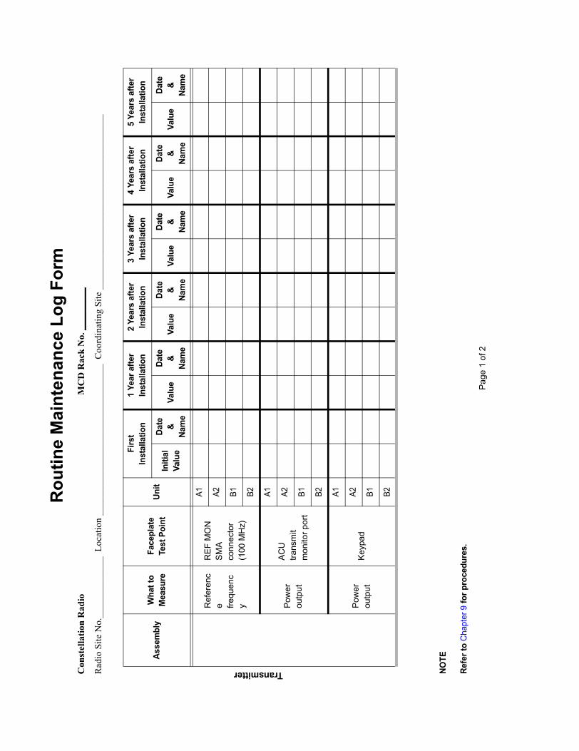
Rou
tine
Mai
nten
ance
Log
For
mC
onst
ella
tion
Rad
ioM
CD
Rac
k N
o. _
____
____
Rad
io S
ite N
o.__
____
____
___
Loca
tion
____
____
____
____
____
____
____
____
Coo
rdin
atin
g Si
te _
____
____
____
____
____
____
____
____
____
Asse
mbl
yW
hat t
o M
easu
reFa
cepl
ate
Test
Poi
ntUn
it
Firs
t In
stal
latio
n1
Year
afte
r In
stal
latio
n2
Year
s af
ter
Inst
alla
tion
3 Ye
ars
afte
r In
stal
latio
n4
Year
s af
ter
Inst
alla
tion
5 Ye
ars
afte
r In
stal
latio
n
Initi
alVa
lue
Date
&
Nam
eVa
lue
Date
&
Nam
eVa
lue
Date
&
Nam
eVa
lue
Date
&
Nam
eVa
lue
Date
&
Nam
eVa
lue
Date
&
Nam
e
Ref
eren
ce fre
quen
cy
REF
MO
N
SMA
conn
ecto
r (1
00 M
Hz)
A1 A2 B1 B2
Pow
er
outp
ut
ACU
tra
nsm
it m
onito
r por
t
A1 A2 B1 B2
Pow
er
outp
utKe
ypad
A1 A2 B1 B2
Page
1 o
f 2
NOTE
Refe
r to
Cha
pter
9 fo
r pro
cedu
res.
Transmitter

Asse
mbl
y
Wha
t to
Mea
sur
e
Face
plat
e Te
st P
oint
Uni t
Firs
t In
stal
latio
n1
Year
afte
r In
stal
latio
n2
Year
s af
ter
Inst
alla
tion
3 Ye
ars
afte
r In
stal
latio
n4
Year
s af
ter
Inst
alla
tion
5 Ye
ars
afte
r In
stal
latio
n
Initi
alVa
lue
Date
&
Nam
eVa
lue
Date
&
Nam
eVa
lue
Date
&
Nam
eVa
lue
Date
&
Nam
eVa
lue
Date
&
Nam
eVa
lue
Date
&
Nam
e
Ref
eren
ce
freq
uen
cy
REF
MO
N
SM
A
connec
tor
(100 M
Hz)
A1 A2 B1 B2
Rec
eive
d S
ignal
Leve
l
Take
the
read
ing
from
the
Key
pad
A1 A2 B1 B2
Page
2 o
f 2
NOTE
S:1.
Mea
sure
men
ts a
t the
Rec
eive
r Ass
embl
y ar
e no
t req
uire
d by
th
e FC
C. T
his
page
is fo
r cus
tom
er’s
info
rmat
ion
only
.2.
Refe
r to
Cha
pter
9 fo
r pro
cedu
res.
Receiver

Harris Microwave Communications DivisionService Registration Form
To facilitate warranty support and to receive product update information, please complete and return this form to our customer service department.
By fax: 514-421-3555
By e-mail: [email protected]
By mail: Harris CorporationMicrowave Communications Division3 Hotel de VilleDollard-des-Ormeaux, QuebecCANADA H9B 3G4
Attention: Technical Assistance Center
The Technical Assistance Center is available on the Internet at http://www.microwave.harris.com/cservice/.
Please print:
Company Name: _____________________________________
Requester’s Name: ___________________________________
Title _______________________________________________ Dept. _____________________________
AddressCity_________________________________________ State/Province ____________________________
ZIP/Postal Code ______________________________ Country _________________________________
Telephone Number ____________________________ Fax Number ______________________________
E-mail_______________________________________
Original Sales Order/PO Number _______________
(Sales order number is found in your documentation and on the equipment rack base plate.)

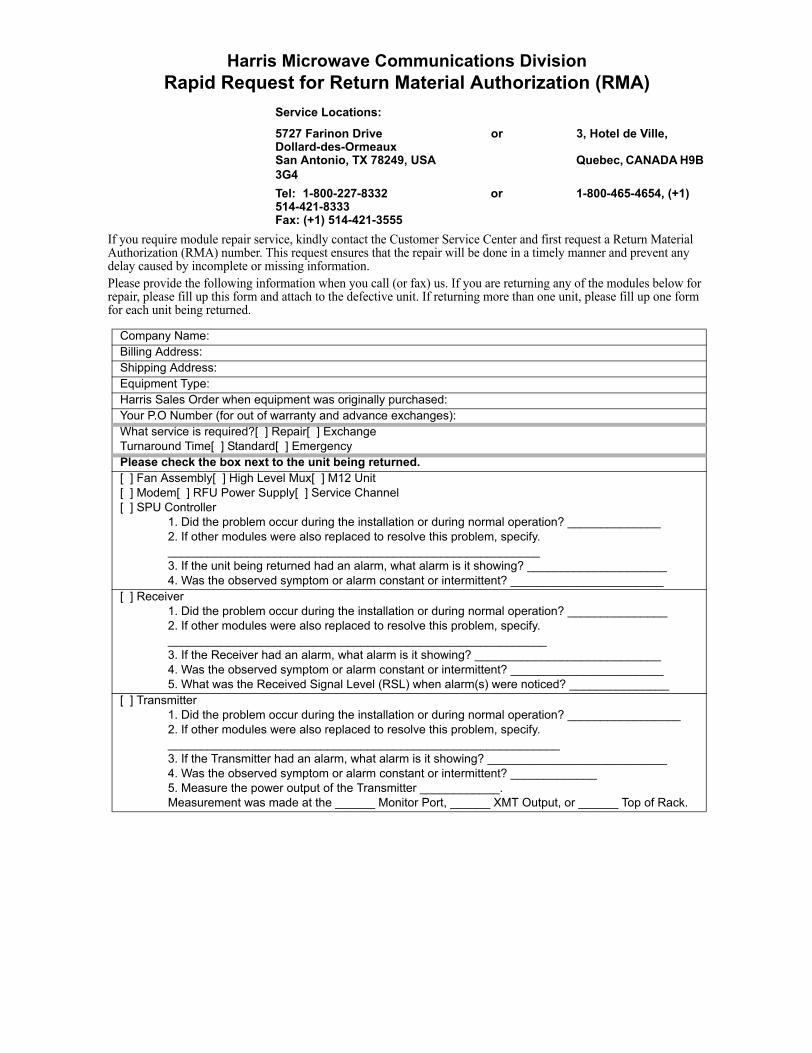
Harris Microwave Communications DivisionRapid Request for Return Material Authorization (RMA)
Service Locations:
5727 Farinon Drive or 3, Hotel de Ville, Dollard-des-OrmeauxSan Antonio, TX 78249, USA Quebec, CANADA H9B 3G4Tel: 1-800-227-8332 or 1-800-465-4654, (+1) 514-421-8333Fax: (+1) 514-421-3555
If you require module repair service, kindly contact the Customer Service Center and first request a Return Material Authorization (RMA) number. This request ensures that the repair will be done in a timely manner and prevent any delay caused by incomplete or missing information.Please provide the following information when you call (or fax) us. If you are returning any of the modules below for repair, please fill up this form and attach to the defective unit. If returning more than one unit, please fill up one form for each unit being returned.
Company Name:Billing Address:Shipping Address:Equipment Type:Harris Sales Order when equipment was originally purchased:Your P.O Number (for out of warranty and advance exchanges):What service is required?[ ] Repair[ ] ExchangeTurnaround Time[ ] Standard[ ] EmergencyPlease check the box next to the unit being returned.[ ] Fan Assembly[ ] High Level Mux[ ] M12 Unit[ ] Modem[ ] RFU Power Supply[ ] Service Channel[ ] SPU Controller
1. Did the problem occur during the installation or during normal operation? ______________2. If other modules were also replaced to resolve this problem, specify.________________________________________________________3. If the unit being returned had an alarm, what alarm is it showing? _____________________4. Was the observed symptom or alarm constant or intermittent? _______________________
[ ] Receiver1. Did the problem occur during the installation or during normal operation? _______________2. If other modules were also replaced to resolve this problem, specify._________________________________________________________3. If the Receiver had an alarm, what alarm is it showing? ____________________________4. Was the observed symptom or alarm constant or intermittent? _______________________5. What was the Received Signal Level (RSL) when alarm(s) were noticed? _______________
[ ] Transmitter1. Did the problem occur during the installation or during normal operation? _________________2. If other modules were also replaced to resolve this problem, specify.___________________________________________________________3. If the Transmitter had an alarm, what alarm is it showing? ___________________________4. Was the observed symptom or alarm constant or intermittent? _____________5. Measure the power output of the Transmitter ____________. Measurement was made at the ______ Monitor Port, ______ XMT Output, or ______ Top of Rack.

GLO
SS
AR
Y
GLOSSARY
A
ACU. Antenna Coupling Unit.
A/D. Analog to Digital.
ADM. Add-Drop Multiplexer.
AGC. Automatic Gain Control; automatic gain adjustment of a varying input signal level to produce a constant output signal level.
AIS. Alarm Indication Signal.
ALC. Automatic Level Control.
AMI. Alternate Mark Inversion.
ANSI. American National Standards Institute.
AUX. Auxiliary port.
B
B8ZS. Bipolar with Eight Zero Substitution.
baseband. A frequency band occupied by a modulating information signal.
Bellcore. Bell Communications Research, Inc. (source of telephony standards in the U.S.).
BER. Bit Error Ratio.
BERT. Bit Error Ratio Tester.
BPF. BandPass Filter.
BPV. BiPolar Violation.
BW. BandWidth.
C
CAN. Controller Area Network. An interface standard (ISO 11898) for interconnecting microcontrollers.
CEPT. Conference Européen des Administrations des Postes et des Télécommunications.
CIT. Craft Interface Terminal.
Harris Corporation Constellation™

G-2
D
DMM. Digital MultiMeter.
DRAM. Dynamic Random-Access Memory.
D connectors, subminiature. The size of the subminiature D connector is specified by the standard shell size and the number of connectors. For example, a 15-pin connector is referred to as a DA-15. See the following table.
DTMF. Dual-Tone MultiFrequency.
DUART. Dual Universal Asynchronous Receiver-Transmitter.
E
EEPROM. Electronically Erasable Programmable Read-Only Memory.
EFS. Error-Free Seconds.
EFSR. Error-Free Seconds Ratio.
EMI. Electro-Magnetic Interference.
EPLD. Erasable Programmable Logic Device.
EQM. Eye Quality Monitor.
ES. Errored Seconds.
ESR. Errored Seconds Ratio.
ET. Elapsed Time.
ETSI. European Telecommunications Standards Institute.
F
FarScan. Harris’ network management system software.
FCC. Federal Communications Commission (U.S.).
Standard Shell Size No. of Connectors
E 9
A 15
B 25
C 37
D 50
Constellation™ 2002 June 20

Glossary G-3
GLO
SS
AR
Y
FD. Frequency Diversity. Diversity transmission and reception in which the same information signal is transmitted and received simultaneously on two or more independently fadings carrier frequencies.
FEC. Forward Error Correction.
H
HLM. High Level Mux.
hop. The span between a transmitter and a receiver.
I
IEC. International Electrotechnical Commission.
IF. Intermediate Frequency; frequency below the radio frequency.
ISO. International Organization for Standardization.
L
LED. Light-Emitting Diode.
LNA. Low-Noise Amplifier.
LO. Local Oscillator.
Loopback Test. A test of the coupling of a signal from the transmitting path back to the local receiving path.
LOS. Loss Of Signal.
LVDS. Low-Voltage Differential Signaling.
M
M12. A multiplexing method that transforms between 1 DS1 up to 4 DS1 input/outputs and a T2 output/output.
M2X. A multiplexing method that transforms between 1 T2 up to 7 T2 input/outputs and a T3 output/output.
MCD. Microwave Communications Division, formerly Farinon Division.
MHSB. Monitored Hot StandBy.
MIB. Management Information Base.
N
NC. Normally Closed; No Connection.
Harris Corporation Constellation™

G-4
Noise Figure. The ratio of the output noise power to the portion of the output noise power stemming from thermal noise at the input at standard noise temperature.
NP. NonProtected.
O
OCXO. Ovenized (proportional Control) Crystal Oscillator.
OEM. Original Equipment Manufacturer.
P
PDU. Protocol Data Unit.
PLL. Phase-Locked Loop.
Q
QUICC. QUad Integrated Communications Controller.
R
RCS. Reverse Channel Switch.
RF. Radio Frequency.
RIP. Routing for Internet Protocol.
RMA. Return Material Authorization.
RMS. Rack-Mounting Space.
RSL. Received Signal Level.
RX. Receiver.
S
SCAN. System Control And Alarm Network. Harris’ proprietary standard for sending alarm/status/control messages over a serial port.
SD. Space Diversity. Pertaining to signal transmission and reception in which two or more separate and independent propagation media or paths are used for transmitting the same information.
SES. Severely Errored-Seconds.
SESR. Severely Errored-Second Ratio.
SNMP. Simple Network Management Protocol.
Constellation™ 2002 June 20

Glossary G-5
GLO
SS
AR
Y
SNR. Signal-to-Noise Ratio.
SPSC. Spare Products Support Center.
SPU. Signal Processing Unit.
SPUR. Extended SCAN port. A communications channel branching of from the trunk and generally carrying less traffic than the trunk.
T
TCP/IP. Transmission Control Protocol/Internet Protocol.
T/I. Threshold-to Interference ratio.
TIA. Telecommunication Industries Association.
TSL. Transmitted Signal Level.
TTL. Transistor-Transistor Logic.
TvX. Transmitter.
U
UBER. Uncorrected Bit Error Ratio.
V
VCO. Voltage-Controlled Oscillator.
VF. Voice Frequency.
X
XO. Crystal Oscillator.
Harris Corporation Constellation™

G-6
Constellation™ 2002 June 20

IND
EX
A P P E N D I X
IINDEX
Numerics1:N protection, M12 Units 1-1310Base-T A-83DS3 capacity use 6-1
AA direction 1-15acquisition time 4-24, 9-3ACU 4-19, 4-28, 9-6
cable, Transmitter 12-12, 12-13expansion port 4-19flange 4-19technical data 4-19transmit monitor port 4-19
ADD/DROP command, Configuration submenu B-10
ADD/DROP, configuring 6-6add-drop in repeater configuration 1-3Address
Master 10-5Target 10-5
addressmailing, Technical Assistance Center
13-6manager not used 8-9, 8-10ordering spare parts 13-1Spare Products Support Center 13-1to disable the static entry 8-8
adjusting the frequency 4-24, 9-3adjusting the RF output power 4-30, 9-8
Keypad procedure B-12alarm I/O pinouts 4-18
Constellation™
alarm inputs for customer 1-14alarm LEDs 1-3alarm list for relay output A-6alarm messages, diagnosing 11-3alarm path block diagram 11-6alarm reporting 1-14Alarm submenu B-6
glossary 11-7alarm wires, customer-configured 4-15alarm, external connector 1-4alarm/control connector, external A-5alarms monitoring 1-16alarms, customer-configured 4-16, A-5allowed manager 8-9alternate bank 10-10ALTERNATE S/W command, Control
submenu B-9alternate software 10-10annual maintenance requirement 4-27, 9-
1, 9-5antenna 2-2
aligning at the Receiver Assembly 4-8connecting 4-18connecting to the Constellation 4-6
Antenna Coupling Unit 1-4antistatic strap 12-1ATPC 6-5, B-6ATPC command, Configuration submenu
B-10ATPC threshold B-12attenuation/equalization, line 4-14
Harris Corporation

I-2
automatic switchingalgorithm 1-13
automatic transmitter power control 1-13AUX port 4-13, 10-3, A-8
pinouts A-10
BB direction 1-15backplane
battery block and customer-configuredalarms 4-22
customer access area 4-13battery noise requirement 4-20battery polarity 4-20battery power wires
connecting 4-6battery power wiring
repeater 4-22terminal 4-20
battery voltage and noise, testing 4-20battery voltage, testing 4-6BER test
tributary 5-11BER, Performance submenu B-8bill of material, checking against 3-2bill of materials E-2block diagram, alarm path 11-6BNC connector 4-13, A-8
specifications A-11BNC connectors 10-3booting software 10-10break in the loop D-1business hours, Technical Assistance
Center 13-5
Ccable
power 4-21rack-grounding 4-2twisted-pair 8-2
cable length, interconnection cables 4-14cable ties 4-2cable to link the VF and pilot signals D-3cables connecting the VF and data D-4cables, interconnection
connecting 4-6
Constellation™
cablinginterconnection 4-12
cabling requirements, interconnection 4-14CAN port 4-13, 10-3, A-8
cable connection 4-11pinouts A-10terminated 4-11
CanadaSpare Products Support Center 1-1, 13-
2technical support numbers 1-1, 13-5training center 13-7
charges, repair 13-2circuit breaker 4-21, 4-23Class A
computing device 2-4limits for radiated emissions 2-4
classes for customers 13-6CLK command, Alarm submenu B-6collect shipments 13-8COMM PORT SETTINGS command,
Configuration submenu B-10Community ID 8-4condition of merchantability 13-8configuration
rack-mounting for repeater 1-5configuration alarm 6-5Configuration submenu
hidden menu B-10, B-12Keypad menu B-10
configuration, factory 3-1configuring
ADD/DROP 6-6Constellation Radio 6-1High Level Mux 7-1
connectingbattery power wires 4-6customer-configured alarm wires 4-6interconnection cables 4-6
connectorexternal alarm/control A-5
connectors, for customer cables A-7Constellation network 8-2Constellation Radio 1-2
doors 1-3elements 1-4platform 1-3repeater system 12-5
2002 June 20
Index I-3
IND
EX
Constellation software, menu format B-5Control submenu
hidden menu B-9Control submenu, Keypad menu B-9cost of labor, customer’s 13-8counter, frequency 4-3coupling loss 4-29, 4-30, 9-7, 9-8courses for customers 13-6craft interface 1-16customer access area, backplane 4-13customer interconnection cables A-7customer service 1-1
e-mail address F-5mailing address F-5
customer support 1-1customer training 13-6
telephone numbers 13-6customer-configured alarm wires 4-15
connecting 4-6customer-configured alarms 1-14, 4-16,
A-5customer-supplied tools 4-2
DD connector, subminiature, table G-2damage, moisture 2-3damaged package 3-2DATA BRIDGE command, Configuration
submenu B-10data link layer 8-2DATA PORT
location 4-13, A-8pinouts A-10
data port 10-3DATA PORT command, Configuration
submenu B-10DATA PORT connector A-10data rates 6-11DE-9 10-3DE-9 connector B-3
location 4-13, A-8pinouts A-11
defective product 13-7defective unit, returning 12-3delay between receivers 1-13destinations, TRAP 8-9
Harris Corporation
diagnosing alarm messages 11-3diagnosing through the Keypad 1-16dialog box
Download Port Settings 10-7Software download setup 10-4
digital channel bank 4-13, 4-14discontinued items repair 13-2disrupting traffic 5-1doors
removable 1-3doors, Constellation
open and remove 4-9, 12-3removing 4-10, 12-4view 4-9, 12-3
Download Port Settings dialog box 10-7downloading new software 10-1, 10-4, 10-
10downloading the software 10-8DS1 connector pinouts A-12DS1 cross-connect 4-13, 4-14DS3 mode 6-4
EE1 wayside port
location 4-13, A-8specification A-11
earthquake 4-20electrical precautions 2-1elements, Constellation Radio 1-4e-mail address
customer service F-5Technical Assistance Center F-5
emulator B-2EQUALIZER command, Configuration
submenu B-10equipment
inspection 3-1equipment rack location 3-1equipment spacing 3-1equipment, test 4-2Errored Seconds alarm 6-9, A-6errorless function
switching Receiver Assembly 12-19errorless switching 1-13Ethernet 8-2
port 10-3
Constellation™

I-4
Ethernet portlocation 4-13, A-8pinouts A-10specification A-8
evaluation fee 13-3expansion port, ACU 4-19external alarm/control connector 1-4, A-5external control relay 1-14external pilot D-1EXTERNAL PILOT command, Configuration
submenu B-10
Ffactory configuration 3-1factory-tested, Constellation 4-1failure
Power Supply 12-22Fan Assembly 1-4, 4-13
connector location 4-13, A-8installing 12-7removing 12-5
FAN command, Configuration submenu B-10
FarScan 1-16FarScan port 10-3, A-9
location 4-13, A-8pinouts A-11
fault LED indicators 1-14fax number
repair 13-4Spare Products Support Center 13-2Technical Assistance Center 13-5
FCC F-4requirements 4-1, 9-1rules 2-4
FCC Part 15 2-4FCC Title 47 2-4, 4-24, 9-3fee, evaluation 13-3field-replaceable unit 1-14flange, ACU 4-19flexible waveguide 4-20form
RMA F-7Routine Maintenance Log 4-1, F-3Service Registration F-5
forms F-1
Constellation™
frequencyadjusting 4-24, 9-3
frequency counter 4-3, 4-24, 4-26, 9-4, 12-3, 12-13
frequency diversityTx and Rx terminal 1-5
frequency, referencemeasuring at the Receiver Assembly 4-
7measuring at the Transmitter Assembly
4-7front view
High Level Mux 12-26M12 Unit 12-33Modem 12-24Power Supply 12-21Receiver Assembly 12-15Service Channel 12-31SPU Controller 12-32Transmitter Assembly 12-8
full duplex 6-10function, Keypad keys B-4fuse 4-21fuse alarm relay 4-17, A-6fuse chart 4-23Fuse Panel 4-6, 4-21, 4-23fuse panel 1-4fuses 4-6, 4-22
Ggateway unit 10-2glossary G-1
Alarms 11-7ground the waveguide 4-19grounding
radio rack 4-6, 4-9verify 2-2
grounding strap 2-3guidelines, troubleshooting 11-1
Hhalf-duplex communication 6-10hand tools 12-3handset connector 4-13, 10-3, A-8Harris Premier Web site 11-1Hex File 10-5
2002 June 20

Index I-5
IND
EX
hidden menuConfiguration submenu B-10, B-12Control submenu B-9Performance submenu B-8
High Level Mux 1-4, 1-13configuring 7-1front view 12-26installing 12-27LED indicators, location 12-26locking traffic 12-27removing 12-26
HLM-155installing 12-29locking traffic 12-28, 12-30
HLM-155 electrical interface, loopback test 5-12
HLM-3xDS3installing 12-30
hours, businessTechnical Assistance Center 13-5
IIF cable
receiver 12-7IF filter
Receiver Assembly 12-19IF filter, removing and installing, Receiver
Assembly 12-17IF loopback test 5-2impulse noise, source of 3-1injury caused by improper practices 2-1inspection, equipment 3-1installation
waveguide 4-19installation procedures 4-6
detailed 4-9installing
Constellation radio rack 4-9High Level Mux 12-27HLM-155 12-29HLM-3xDS3 12-30M12 Unit 12-34Modem 12-25Power Supply 12-22Receiver Assembly 12-20Service Channel 12-32SPU Controller 12-33Standby M12 Unit 12-34
Harris Corporation
interconnection cablesconnecting 4-6
interconnection cables for customers A-7interconnection cabling 4-12
requirements 4-14interference 2-4Internet address
customer service F-5Technical Assistance Center F-5
IP parameter changes 8-8IP routing 8-3
table 8-3IP ROUTING command, Configuration
submenu B-10
JJP1 settings 12-16
KKeypad 1-14, 1-15, 1-16, 4-7, A-6, B-1
adjusting the Tx frequency 4-24, 4-26,9-4
cable B-2function B-1layout B-3main menu B-5picture 12-6pinouts A-10, B-3port A-9port location 4-13, A-8procedure
adjusting the RF output power 4-30, 9-8
removing 12-5routine maintenance 9-1screen format B-2serial interface B-2technical data B-3
Keypad menuAlarm B-6Configuration B-10Control B-9Performance B-8Status B-7
Keypad port 10-3
Llabel, transmit monitor port 4-28, 4-29,
9-6, 9-7
Constellation™

I-6
LAN 8-1leaks, waveguide 4-20LED indicators 4-23, 11-3
fault 1-14Modem 12-24observing 9-1online 1-14Receiver Assembly 4-27, 9-11, 12-15SPU Controller 12-32status 1-14Transmitter Assembly 4-25, 9-5, 12-9
LED indicators, locationHigh Level Mux 12-26M12 Unit 12-33Power Supply 12-21Service Channel 12-31
liability 13-8license requirements 4-24, 9-3line attenuation/equalization 4-14LNC, Receiver Assembly 12-16LO MON frequency calculation C-2local download 10-1Local Major 4-17, A-6Local Minor 4-17, A-6location
equipment rack 3-1Spare Products Support Center 13-1
LOCK commandAlarm submenu B-6Control submenu B-9
locking trafficHigh Level Mux 12-27HLM-155 12-28, 12-30Modem 12-25Receiver Assembly 12-19standby Receiver Assembly 12-22standby Transmitter Assembly 12-22
loop system 7-2, 12-27, D-1Service Channel D-1
loop systems, two separate D-5LOOPBACK command
Alarm submenu B-6Control submenu B-9
loopback testHLM-155 electrical interface 5-12IF 5-2tributary 5-3tributary remote 5-4
Constellation™
loopback tests 5-1performing 4-7
LOSalarm 6-9, A-6
MM12 PROTECTION command, Configuration
submenu B-10M12 Unit 1-4, 1-13, 1-15
front view 12-33installing 12-34LED indicators, location 12-33PROTECT command 12-34protection 6-5removing 12-34selecting the capacity 6-3
M12 Unit, Standbyinstalling 12-34RELEASE command 12-34, 12-35removing 12-34
magnetic fields 3-1mailing address
customer service F-5spare parts 13-1Technical Assistance Center 13-6, F-5
main menu, Keypad B-5maintenance
annual requirement 4-27, 9-1, 9-5routine 9-1
Maintenance Log form 4-1, 9-1Major Alarm 6-9, A-6manager, allowed 8-9Manual Control, configurable 6-9, A-6MANUAL MUTE command, Alarm submenu
B-6Master Address 10-5master site 6-11master, selecting 6-10MCX connector
Receiver Assembly 12-16Transmitter Assembly 12-10
measurementReceiver Assembly 9-10transmitter power 4-27, 9-5
measurementsFCC requirements 9-1
measurements procedure 9-3
2002 June 20
Index I-7
IND
EX
measuringreference frequency, Receiver Assem-
bly 4-7reference frequency, Transmitter As-
sembly 4-7transmitter power 4-27, 9-5
menu format, Constellation software B-5merchantablility, condition of 13-8meter, power 4-3MHSB repeater 1-5MHSB Tx with SD Rx terminal 1-5Minor Alarm 6-9, A-6model number E-2Modem 1-4
front view 12-24installing 12-25LED indicators, location 12-24locking traffic 12-25removing 12-24torque specification 12-25
Modem and Cable Modem in repeater system 12-25
module exchange 13-2moisture buildup 2-3moisture-sensitive device 2-3MONITOR port A-9
location 4-13, A-8pinouts A-10
Monitor port 10-3monitor port, transmit
connecting power meter 4-28, 9-6label 4-28, 4-29, 9-6, 9-7location 4-29, 9-7
monitor port, transmit, ACU 4-19monitored hot standby 1-13monitored hot standby terminal 1-5MSD storage requirements 2-3multimeter 4-20multimeter, digital 4-3multiple loop system D-4multiplier
location on Receiver Assembly 12-16multiplier-filter
removing and installing onto ReceiverAssembly 12-16
multiplier-filter table C-1
Harris Corporation
multiplier-filter, removing and installing onto Transmitter Assembly 12-10
MUTE commandControl submenu B-9
MUTE, MANUAL command, Alarm submenu B-6
muting the VF and data 6-11
NNetBoss 1-16Netcom IP Interface B-10Netcom Network 8-1Network Management 8-4network management 1-16NETWORK MANAGEMENT command
Configuration submenu B-10Network Manager 8-1new installations, measuring transmitter
power 4-27, 9-5nonprotected terminal 1-5nonprotected Tx/SD Rx 1-5nonrevertive switching 1-13
OOFF HOOK, LOCAL, command,
Configuration submenu B-10off-line Transmitter Assembly, measuring
power 4-28, 4-32, 9-6, 9-9On Line
HLM 6-9, A-6Mod/Tx 6-9, A-6Rx 6-9, A-6
online LED indicators 1-14operating frequency, Transmitter Assembly
4-24, 9-3operation, in residential areas 2-4ordering parts or spares 13-1original equipment list E-2output power, Transmitter 1-14outputs, relay 4-17, A-6
Ppackaging of units 13-3parity 6-11part numbers E-1parts lists, not furnished 13-1
Constellation™
I-8
parts, ordering 13-1PC with emulator, setting up B-2Performance submenu
hidden menu B-8Performance submenu, Keypad menu B-8period, warranty 13-7physical layer 8-2pilot signal D-1PILOT, EXTERNAL, command,
Configuration submenu B-10pinouts A-10
AUX connector A-10CAN connector A-10DE-9 connector A-11DS1 connector A-12Ethernet connector A-10FarScan connector A-11Keypad B-3Keypad connector A-10MONITOR connector A-10RJ-11 connector A-11RJ-45 B-3RJ-45 connectors A-10SPUR connector A-10T1/E1 wayside connector A-10VersaT1lity connector A-10VF Port connector A-10
platform, Constellation Radio 1-3Port Setup 10-6power
top of the rack 4-30, 9-8turning on 4-7
power breakeroff 4-9
power cable 4-21power calibration B-12power distribution panel 4-23power levels
recording 4-32, 9-9power meter 4-3, 4-7, 12-3, 12-13, 12-14power meter, connecting to ACU 4-28, 9-6power output
verifying 4-7power precautions 4-2power runs 4-21power sensor 4-3
Constellation™
Power Supply 1-4, 4-24, 9-3failure 12-22front view 12-21installing 12-22LED indicators, location 12-21removing 12-22switch location 12-21turning on the switch 4-7, 4-23
Power Supply A1, replacement precaution 11-3, 12-2
precautionwaveguide 2-2
precautions 12-1electrical 2-1power 4-2radiation hazard 2-2safety and equipment damage 2-1simultaneous replacement of modules
11-3, 12-2procedure
adjusting the RF output power 4-30, 9-8
measurements 9-3traffic-affecting 4-28, 9-6
proceduresinstallation 4-6
product support 13-1Product Support Engineer 13-5product update information F-5product warranty terms 13-7PROTECT command
M12 Unit 12-34protection
M12 Unit 6-5protection switching 1-13protection system
verifying 4-8protocol layers 8-2publications, related 1-2Purchase Order Number 13-4
Rrack
grounding 4-6, 4-9rack installation 4-9rack, location of equipment 3-1rack-grounding cable 4-2radiation hazard 2-2
2002 June 20

Index I-9
IND
EX
radio communications interference 2-4radio rack, grounding 4-6, 4-9REBOOT SYSTEM command 8-8
Configuration submenu B-10rebooting software 10-10received signal level
far-end Receiver 1-14Receiver Assembly 1-4
front view 12-15IF filter 12-19installing 12-20LED indicators 4-27, 9-11LED indicators, location 12-15LNC 12-16locking traffic 12-19log form F-4MCX connector 12-16multiplier, location 12-16removing 12-19removing and installing multiplier-filter
12-16test points, location 4-27, 9-11, 12-15torque specification 4-27, 9-11, 12-15,
12-20what to measure F-4
Receiver Assembly measurement 9-10record, transmitter measurements 4-1records of Transmitter measurements 9-1Redwood Shores address 13-6REF MON frequency, measuring 9-10reference frequency
measuring at the Receiver Assembly 4-7
measuring at the Transmitter Assembly4-7
regulatory compliance 2-4relay
external control 1-14fuse alarm 4-17, A-6outputs 4-17, A-6specifications 4-16, A-5
RELEASE commandStandby M12 Unit 12-34, 12-35
remote download 10-2
Harris Corporation
removingHigh Level Mux 12-26M12 Unit 12-34Modem 12-24Power Supply 12-22Service Channel 12-31SPU Controller 12-33Standby M12 Unit 12-34Transmitter Assembly 12-12
removing for easier installation 4-13repair
charges 13-2fax number 13-4telephone number 13-4
repair and return 13-2repair service locations 13-4repairing
equipment 13-1other manufacturer’s equipment 13-7
repeaterMHSB 1-5rack-mounting configuration 1-5Service Channel D-1
repeater configurationadd-drop 1-3
repeater system 7-2, 12-25, 12-27front view 12-5
replacement of equipment 13-1replacement of modules, simultaneous
11-3, 12-2replacement unit 13-2reporting damaged goods 3-2residential area, operation in 2-4residual BER floor 4-24, 9-3responsibility limits 2-1return freight 13-3Return Material Authorization 13-4
address F-7fax number F-7form F-7telephone number F-7
returning products 13-8RF output power
verifying 4-7RF power
adjusting 4-30, 9-8RF units
switching 4-32, 9-10, 12-14, 12-23
Constellation™
I-10
RIP tables 8-3, 8-7RJ-11 10-3
location 4-13, A-8pinouts A-11
RJ-45location 4-13, A-8pinouts A-10, B-3
RJ-45 connector 4-11, 10-3RMA Form F-1routine maintenance 9-1Routine Maintenance Log form 4-1, F-3routing protocol 8-3routing table, IP 8-3routing tables, static 8-7RS-232 A-9, B-3RS-422 A-8RS-423 A-9RSL
Status submenu B-7running the new software
later 10-9now 10-9
Ssafety precautions 2-1sales documents 13-1sales invoice 13-1sales order number F-5Sales Order Specific Information 4-1, 4-9SDH 4-13, A-8second break in the loop D-2seismic disturbance 4-20sensor, power 4-3Service Channel 1-4, 4-16, A-5
configuring 4-8different systems D-1front view 12-31installing 12-32LED indicators, location 12-31removing 12-31repeater D-1
Service Registration form F-1, F-5
Constellation™
service-affecting procedureHigh Level Mux 12-27HLM-155 12-28HLM-3xDS3 12-30Modem removal 12-25Receiver Assembly 12-19
setting up a PC with emulator B-2shelf configurations 1-5shielded cables 2-4shipping time
replacement unit 13-2Signal Degradation alarm 6-9, A-6simultaneous replacement of modules
11-3, 12-2single loop system
using repeaters D-2with two terminals at repeater site D-3
slave terminals 6-11Sliding Window Size 10-5SMA wrench 12-3SNMP 1-16, 8-8, A-8SNMP command, Configuration submenu
B-10SNMP managers 8-9software
downloading 10-4running it now 10-9upgrade 10-3version 1-1
Software download setup dialog box 10-4software, booting 10-10space diversity receivers 1-13spacer adapter 4-19spacing, equipment 3-1spare parts
ordering 13-1Spare Products Support Center 13-1specifications, relay 4-16, A-5SPU Controller 1-4, 1-13, 1-14, 4-16, A-5
downloading new software into 10-4front view 12-32installing 12-33LED indicators 12-32rebooting 8-8removing 12-33replacement precaution 11-3, 12-2
SPUR port 4-13, 10-3, A-8pinouts A-10
2002 June 20
Index I-11
IND
EX
standard product warranty terms 13-7Standby M12 Unit
installing 12-34RELEASE command 12-34, 12-35removing 12-34
StarView 1-16, A-8static routing tables 8-7station authorization 4-24, 4-25, 9-3status LED indicators 1-14Status submenu, Keypad menu B-7storage requirements, sensitive devices 2-
3strap
antistatic 4-2, 12-1grounding 2-3
subminiature D connector table G-2switch
Transmitter Assembly 4-25, 9-5, 12-9, 12-13
turning on the Power Supply 4-7, 4-23switch, location
Power Supply 12-21switch, turning on the Transmitter
Assembly 4-7, 4-23switching
errorless 1-13nonrevertive 1-13protection 1-13
switching algorithm, automatic 1-13switching of RF units 4-32, 9-10, 12-14,
12-23symbol
exclamation point 1-2pencil and pad 1-2stop sign 1-2
symbols 1-1sync alarm D-2Sync Loss A alarm 6-9, A-6Sync Loss B alarm 6-9, A-6synchronization
source timed 7-2, 12-25, 12-27system administrator 12-13Systems Application Information 1-5
TT1 wayside port
location 4-13, A-8
Harris Corporation
T1/E1 wayside portpinouts A-10
tablemultiplier-filter C-1subminiature D connector G-2
Target Address 10-5TCP/IP-to-Netcom connectivity 8-1Technical Assistance Center 13-5
e-mail address F-5fax numbers 13-5Internet address F-5mailing address 13-6, F-5telephone numbers 13-5
technical dataKeypad B-3
technical data, ACU 4-19Technical Support 13-5telephone handset connector 10-3telephone number
customer training 13-6Customer Training Department 13-6repair 13-4Spare Products Support Center 13-2Technical Assistance Center 13-5worldwide 1-1
temperature, Tx reading B-7terminal 1-5
FD Tx and Rx 1-5MHSB Tx with SD Rx 1-5nonprotected 1-5
terminated CAN port 4-11termination of transmitter 2-2test data 4-1test equipment 4-2, 12-3, 12-13test points, location
Receiver Assembly 4-27, 9-11, 12-15Transmitter Assembly 4-25, 9-5, 12-9
ties, cable 4-2tools 12-3tools, customer-supplied 4-2torque specification
Modem 12-25Receiver Assembly 4-27, 9-11, 12-15,
12-20Transmitter Assembly 4-25, 9-5, 12-9,
12-13, 12-16traffic disruption 1-13, 5-1
Constellation™

I-12
traffic-affecting procedure 4-28, 9-6, 12-12
training centers 13-7training, customer 13-6
telephone numbers 13-6transmit monitor port
ACU 4-19connecting power meter 4-28, 9-6location 4-29, 9-7
Transmitter Assembly 1-4ATPC enabled 1-14front view 12-8installing 12-12log form F-3MCX connector 12-10measurements 9-1, F-3measuring the reference frequency 4-7off-line, measuring power 4-28, 4-32,
9-6, 9-9power level 12-14record operating frequency 4-24, 9-3removing 12-12removing and installing multiplier-filter
12-10switch 4-25, 9-5, 12-9, 12-13test points, location 4-25, 9-5, 12-9torque specification 4-25, 9-5, 12-9,
12-13, 12-16Transmitter Assembly A1, replacement
precaution 11-3, 12-2transmitter filter 4-24, 9-3transmitter measurements record 4-1transmitter power, request for increased
1-14Transmitter switch, turning on 4-7, 4-23Transmitter, temperature reading B-7transmitter, termination of 2-2trap
community 8-10destinations 8-9enable/disable 8-10management 8-10repeat 8-10
tributary BER test 5-11tributary loopback test 5-3tributary remote loopback test 5-4troubleshooting
guidelines 11-1
Constellation™
turning onthe power 4-7the Power Supply switch 4-7, 4-23Transmitter switch 4-7, 4-23
twisted-pair cable 8-2two separate loop systems D-5
Uunpacking procedure 3-2unrepairable units 13-3
Vverify grounding 2-2verifying RF output power 4-7VersaT1lity port 10-3, A-9
location 4-13, A-8pinouts A-10
version, software 11-1VF port 10-3VF ports
location 4-13, A-8pinouts A-10
voltmeter, digital 12-3VT100 terminal emulator B-1VT100-compatible terminal 1-16
Wwarming up the Constellation 4-7, 4-23warning labels 2-1warnings 2-1warranty 13-1
other equipment manufacturer 13-7warranty period 13-7watchdog 10-10waveguide
flexible 4-20grounding 4-19installing 4-19leaks 4-20precaution 2-2
waveguide termination 4-19wayside connector 10-3wayside port
E1 specification A-11E1, location 4-13, A-8T1, location 4-13, A-8T1/E1 pinouts A-10
2002 June 20

Index I-13
IND
EX
Web site, Harris 11-1wire size, power run 4-21worldwide customer service telephone
number 1-1
Harris Corporation
Constellation™
I-14
Constellation™
2002 June 20

IMN-112871-E07
Microwave Communications Division 350 Twin Dolphin Drive Redwood Shores, CA USA 94065-1421
www.harris.comUSA 1-800-227-8332 1-650-594-3800
next level solutions