installation instructions transform motorized acoustical banner banner... · 2017-08-29 ·...
TRANSCRIPT

Installation InstructionsTransform™
Motorized Acoustical Banner
©Wenger Corporation 2017 Printed in USA 08/17 Part #213A099-07
Wenger Corporation, 555 Park Drive, P.O. Box 448, Owatonna, Minnesota 55060-0448
Questions? Call.....USA: 800-4WENGER (493-6437) • Worldwide: 1-507-455-4100 • www.wengercorp.com
ContentsImportant User Information. . . . . . . . . . . . . . . . . . . . . . . . . . . . 2
General. . . . . . . . . . . . . . . . . . . . . . . . . . . . . . . . . . . . . . . 2Manufacturer . . . . . . . . . . . . . . . . . . . . . . . . . . . . . . . . . . 2Intended Use . . . . . . . . . . . . . . . . . . . . . . . . . . . . . . . . . . 2Warranty . . . . . . . . . . . . . . . . . . . . . . . . . . . . . . . . . . . . . . 2
Safety Precautions . . . . . . . . . . . . . . . . . . . . . . . . . . . . . . . . . . 3Banner Travel Limits. . . . . . . . . . . . . . . . . . . . . . . . . . . . . . . . . 3Required Tools . . . . . . . . . . . . . . . . . . . . . . . . . . . . . . . . . . . . . 4Fasteners . . . . . . . . . . . . . . . . . . . . . . . . . . . . . . . . . . . . . . . . . 4Unpacking. . . . . . . . . . . . . . . . . . . . . . . . . . . . . . . . . . . . . . . . . 5Top Mount Installation . . . . . . . . . . . . . . . . . . . . . . . . . . . . . . . 6Wall Mount Installation . . . . . . . . . . . . . . . . . . . . . . . . . . . . . . 10Final Installation Procedure . . . . . . . . . . . . . . . . . . . . . . . . . . 15Networking Instructions . . . . . . . . . . . . . . . . . . . . . . . . . . . . . 16Programming Instructions . . . . . . . . . . . . . . . . . . . . . . . . . . . 16
Programming the Control Switch . . . . . . . . . . . . . . . . . . 18Programming Shortcut . . . . . . . . . . . . . . . . . . . . . . . . . . 22Programming the Banner Motors . . . . . . . . . . . . . . . . . . 23Testing System Operation . . . . . . . . . . . . . . . . . . . . . . . 31
Limit Setting Tool (Optional) . . . . . . . . . . . . . . . . . . . . . . . . . . 32Drapery Replacement and Tracking. . . . . . . . . . . . . . . . . . . . 32Maintenance . . . . . . . . . . . . . . . . . . . . . . . . . . . . . . . . . . . . . . 32
Cleaning Laminate Surfaces . . . . . . . . . . . . . . . . . . . . . 32Cleaning Fabric . . . . . . . . . . . . . . . . . . . . . . . . . . . . . . . 32Mechanical Check . . . . . . . . . . . . . . . . . . . . . . . . . . . . . 32
Visit the Transform™ Motorized Acoustical Banner web page at www.wengercorp.com for detailed instructions and videos.
Note: Please read and understand the instructions before starting the installation.Note: Review all of the Installation Drawings that were created for placement.Note: It is recommended that two or more people work together during the assembly.Note: If you need additional information, contact Wenger Corporation using the information below.

2
Important User InformationGeneralCopyright © 2017 by Wenger Corporation
All rights reserved. No part of the contents of this manual may be reproduced, copied, or transmitted in any form or by any means including graphic, electronic, or mechanical methods or photocopying, recording, or information storage and retrieval systems without the written permission of the publisher, unless it is for the purchaser’s personal use.
Printed and bound in the United States of America.
The information in this manual is subject to change without notice and does not represent a commitment on the part of Wenger Corporation. Wenger Corporation does not assume any responsibility for any errors that may appear in this manual.
In no event will Wenger Corporation be liable for technical or editorial omissions made herein, nor for direct, indirect, special, incidental, or consequential damages resulting from the use or defect of this manual.
The information in this document is not intended to cover all possible conditions and situations that might occur. The end user must exercise caution and common sense when assembling or installing Wenger Corporation products. If any questions or problems arise, call Wenger Corporation at 1-800-887-7145.
ManufacturerThe Transform Motorized Acoustical Banner is manufactured by:
Wenger Corporation 555 Park Drive Owatonna, MN 55060 800-4WENGER (493-6437) • 1-507-455-4100 www.wengercorp.com
Intended Use· This product is designed to diffuse and/or absorb sounds for vocal or instrumental groups.
· This product is intended for indoor use in normal ambient temperature and humidity conditions.
· This product is intended to be used only as described in these instructions.
WarrantyThis product is guaranteed free of defects in materials and workmanship for three full years from date of shipment. A full warranty statement is available upon request.

3
Safety Precautions
Make sure that anyone installing the banner has read and understands these instructions and is capable of typical assembly procedures.
! CAUTION
Throughout this manual you will find cautions and warnings which are defined as follows.
• WARNING means that failure to follow the instruction may result in serious injury or death. • CAUTION means that failure to follow the instruction may result in serious injury or damage to property.
Read all of these safety instructions before installing.
Always observe and comply with the Warnings and Cautions posted on the system equipment.
! CAUTIONFailure to comply with the Warnings and Cautions in this document can result in damage to property or serious injury.
! CAUTION
The banner can be heavy and difficult to handle. To avoid damage and injury, more than one person is required to install the banner.
! CAUTION
Banner Travel LimitsBanner travel limits can be expected to vary depending on environmental, material and usage factors.
Banner travel is determined by precisely controlling the number of revolutions of the fabric take-up drum. Like any curtain, the actual lower limit of an extended banner will vary with fabric shrinkage or stretch.
Similarly, variations in the upper travel limit should be expected due to changes in fabric thickness. Banners left rolled up for extended periods will cause fabric compression. The thinner fabric will create a smaller diameter roll that will hold less fabric per revolution. This results in the banner stopping before it reaches its expected retracted height. This becomes even more significant with the quilted polypropylene fabrics which compress and expand over a greater thickness range. Variations of several inches can be expected in certain circumstances.
Applications requiring exact repeatable positioning should be discussed with Wenger to determine an appropriate plan to mitigate these variations.
After initial installation, the need for subsequent readjustment of upper and lower limit positions (due to fabric shrinkage , stretch or compression) can be expected and necessary adjustments can be made by the user. Upper and lower limit position adjustments are not subject to Wenger warranty recall.
! CAUTION

4
Required ToolsThe following tools are required for installation:
·Two Chain Lift Motors ·Carpenter’s Level ·Tape Measure
·Drill and bits for mounting to the structure ·Drill and 9/64 and 7/32 bits are required for seismic installations
Fasteners· Because materials and construction of walls can vary, fasteners for attaching the banner to the buildings structure must be determined on site and are not provided. (The only hardware included is used to secure the Banner Assembly to the Wall Mounting Plates and to anchor the closure boards for seismic zone installations).· The installer must choose the appropriate mounting fastener and follow the fastener manufacturer’s installation instructions.· All Mounting fasteners are recommended to be a minimum of 5/16” diameter and of Grade 5 or better quality and must meet local building codes.
Non Seismic InstallationsUse fastening systems appropriate for the load that meet codes in the jurisdiction of installation.
· When using Wall Mounting Brackets, a minimum of two mounting fasteners that attach directly to the load bearing structure are required per Mounting Bracket (per side). At least one of these fasteners in load bearing structure must be in one of the top holes.· For top mounted installations, a minimum of 4 mounting fasteners (two per side) that attach directly to the load bearing structure are required.· Mounting Brackets must be located at least 24” apart and never more than 18” inset from either end of the Banner Assembly Frame.
Seismic InstallationsMounting fasteners selected (not included) must be approved for seismic installations in the jurisdiction of installation.
· When using Wall Mounting Brackets, all four wall mounting plate fasteners must attach directly to the load bearing structure. · For top mounted installations, a minimum of four mounting fasteners (two per side) that attach directly to the load bearing structure are required.· Top mounted installations may require additional custom sway braces as dictated by the installation. These are to be designed by the installer on site. · Mounting Brackets must be located at least 24” apart and never more than 18” inset from either end of the Banner Assembly Frame.
Use in seismic zones requires installation of additional fasteners (included) to further maintain the integrity of the banner assembly during a seismic event:
· Fasteners securing the wall mounting plate to the banner frame.· Fasteners securing the closure boards to the banner frame.· Fasteners securing the Top and Side Mounting Plates to the banner frame.
Follow the instructions in the following Wenger installation procedure for installing these fasteners.
If there are any questions on appropriate fastener selection or installation, contact Wenger directly.
It is the responsibility of the installer to determine the strength of the building structure and to ensure the safety of the banner installation to the building structure.
! WARNINGUsing inferior or improperly installed fasteners could cause the banner to fall. Serious injury or damage may result.
! WARNING

5
1. Unpack the Banner Assembly and Closure Boards from the protective cardboard, Use more than one person and take care to avoid damage.
2. Set the Closure Boards aside to attach later as needed. The Closure Boards are identified as shown.
3. Locate the Motor Address Number (NODE ID) located on the inside of of the End Cover on the motor side. The Node ID is 0A1D0A in this example.
For future reference, record this number along with the Banner’s location and/or function.
Unpacking
More than one person is needed to lift the Banner Assembly.
! CAUTION
Banner Assembly
Closure Boards
Front Closure Board
Rear Closure Board
Top Closure Board

6
1. Locate the Banner installation locations according to the layout plan drawings.2. Attach the Rear Closure Board to the back of the
Banner by tipping it into place. The larger lip must be at the top with the
smaller lip dropping into the bottom groove.3. Seismic Installations Only
Anchor the Closure Board to the Top Banner Frame Extrusion. a. After positioning the
Rear Closure Board, drill a 9/64” diameter pilot hole through the Extrusion and Closure to be centered on the Closure Board and 0.400” up from the bottom edge.
b. Install a #10 x 1/2” Self-Tapping Screw into each hole to constrain the Closure Board.
4. Adjust the Top Mounting Plates side to side to align with the ceiling mounting locations.
5. Seismic Installations Only Anchor the Top Mounting Plates to the Top Banner Frame Extrusion. a. After positioning both Top Mounting Plates
in their final location, drill a 7/32” diameter pilot hole through the Extrusion and Mounting Plate to be centered on each Mounting Plate and 0.400” forward from the back edge of the Extrusion.
b. Install a 1/4 x 3/4” Self-Tapping Screw into each hole to constrain the Mounting Plate.
Top Mount Installation
Rear Closure Board
Top Mounting
Plates
Larger Lip
Smaller Lip
The Banners can be mounted to either ceilings or walls.This is the procedure for mounting the Banner to a ceiling! If mounting the Banner to a wall, go to page 10.
Back Edge
Pilot Hole
Seismic Installations
Only
Seismic Top Mounting Plate
Anchors
Bottom Edge
Pilot Hole
Seismic Installations
Only
0.400”
0.400”
Seismic Rear Closure Board
Anchor

7
6. Attach chain lift rigging to the ceiling and attach mounting hardware to the Top Mounting Plates.
7. Connect the rigging to the Top Mounting Plates.
8. Lift the Banner to the ceiling mounting location and attach it into place using the appropriate mounting hardware.
9. Disconnect the rigging.
10. Adjust to be level using a Carpenter’s Level.
IMPORTANT! Accurate side to side leveling is critical for proper tracking and operation of the Banner. Do not attempt to continue without proper leveling.
Top Mount Installation (continued)
The rigging and mouting hardware must be capable of supporting at least 150 lbs (68 kg) on each end of the Banner.
! WARNING
It is the responsibility of the installer to determine the strength of the building structure and to ensure the safety of the banner installation to the building structure.
! WARNINGUsing inferior or improperly installed fasteners could cause the banner to fall. Serious injury or damage may result.
! WARNING
Carpenter’s Level

8
11. Optional Depending on the rigidity of the structure being mounted to, the unused Side Mounting Plates could rattle inside the Rear Banner Frame Extrusion.
This can be prevented by either of the following methods:
a. Anchor the Side Mounting Plates to the Rear Banner Frame Extrusion. - Drill a 7/32” diameter pilot hole through the Extrusion and Mounting Plate. - Install a 1/4 x 3/4” Self-Tapping Screw into each hole to constrain the Mounting Plate. It is preferable to install the screw at the bottom of the bracket.
b. Insert a Tapered Shim (supplied) into the gap between the inside of the Side Mounting Plate and the Rear Banner Frame Extrusion.
Top Mount Installation (continued)
Tapered Shim
1/4 x 3/4” Self-Tapping
ScrewEnd View shown with Cover Removed
9
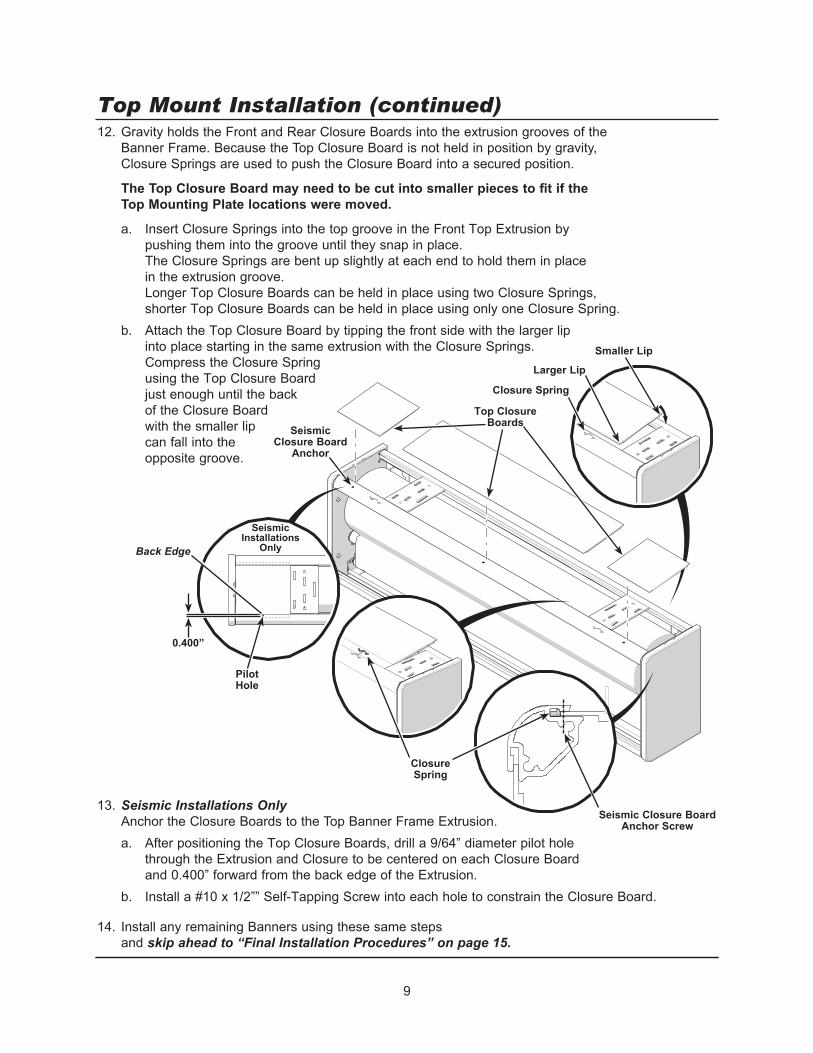
12. Gravity holds the Front and Rear Closure Boards into the extrusion grooves of the Banner Frame. Because the Top Closure Board is not held in position by gravity, Closure Springs are used to push the Closure Board into a secured position.
The Top Closure Board may need to be cut into smaller pieces to fit if the Top Mounting Plate locations were moved.
a. Insert Closure Springs into the top groove in the Front Top Extrusion by pushing them into the groove until they snap in place. The Closure Springs are bent up slightly at each end to hold them in place in the extrusion groove. Longer Top Closure Boards can be held in place using two Closure Springs, shorter Top Closure Boards can be held in place using only one Closure Spring.
b. Attach the Top Closure Board by tipping the front side with the larger lip into place starting in the same extrusion with the Closure Springs. Compress the Closure Spring using the Top Closure Board just enough until the back of the Closure Board with the smaller lip can fall into the opposite groove.
13. Seismic Installations Only Anchor the Closure Boards to the Top Banner Frame Extrusion. a. After positioning the Top Closure Boards, drill a 9/64” diameter pilot hole
through the Extrusion and Closure to be centered on each Closure Board and 0.400” forward from the back edge of the Extrusion.
b. Install a #10 x 1/2”” Self-Tapping Screw into each hole to constrain the Closure Board.
14. Install any remaining Banners using these same steps and skip ahead to “Final Installation Procedures” on page 15.
Top Mount Installation (continued)
Top Closure Boards
Larger Lip
Smaller Lip
Closure Spring
Closure Spring
Seismic Closure Board
Anchor
Back Edge
Pilot Hole
0.400”
Seismic Installations
Only
Seismic Closure Board Anchor Screw

10
1. Locate the Banner installation locations according to the layout plan drawings.
2. Mount both Wall Mounting Plates to the wall with the appropriate fasteners and method as indicated in the “Fasteners” section to be level using a Carpenter’s Level. The slotted holes in the Mounting Plates are only used to provide temporary alignment. Attach the Mounting Plates to the wall using the four corner holes.
Seismic Installations Only The only mounting hardware included in the hardware pack are Bolts and Washers to be used for seismic zone installations.
IMPORTANT! Accurate side to side leveling is critical forproper tracking and operation of the Banner. Do not attempt to continue without proper leveling
Wall Mount Installation
Carpenter’s Level
The Banners can be mounted to either ceilings or walls.This is the procedure for mounting the Banner to a wall! If mounting the Banner to a ceiling, go to page 6.
The Wall Mouting Plates support the entire weight of the Banner.Be sure to secure it to the wall appropriately.The rigging and mouting hardware must be capable of supporting at least 150 lbs (68 kg) on each end of the Banner.
! WARNING
Three seismic mounting holes to mount Banner, used later.
Wall Mounting
Plate
Use the two slotted holes for temporary alignment .
Mount the Plate to the wall using the four corner holes.
Using inferior or improperly installed fasteners could cause the banner to fall. Serious injury or damage may result.It is the responsibility of the installer to determine the strength of the building structure and to ensure the safety of the banner installation to the building structure.
! WARNING

11
3. Gravity holds the Front and Rear Closure Boards into the extrusion grooves of the Banner Frame. Because the Top Closure Board is not held in position by gravity, Closure Springs are used to push the Closure Board into a secured position. a. Insert Closure Springs into the top groove in the Front Top Extrusion by pushing them into the
groove until they snap in place. The Closure Springs are bent up slightly at each end to hold them in place in the extrusion groove.
b. Attach the Top Closure Board by tipping the front side with the larger lip into place starting in the same extrusion with the Closure Springs. Compress the Closure Spring using the Top Closure Board just enough until the back of the Closure Board with the smaller lip can fall into the opposite groove.
4. Seismic Installations Only Anchor the Closure Board to the Top Banner Frame Extrusion. a. After positioning the Top Closure Board, drill a 9/64” diameter pilot hole through the Extrusion
and Closure to be centered on each Closure Board and 0.400” forward from the back edge.b. Install a #10 x 1/2”” Self-Tapping Screw into each hole to constrain the Closure Board.
Wall Mount Installation (continued)
Top Closure Board
Larger Lip
Smaller Lip
Closure Spring
Closure Spring
Seismic Closure Board
Anchor
Seismic Installations
OnlyBack Edge
Pilot Hole
0.400”
Seismic Closure Board Anchor Screw

12
5. Adjust the Side Mounting Plates side to side to align with the wall mounting bracket locations. 6. Optionally, the Rear Closure Board can be attached to the rear of the Banner.
The larger lip must be at the top with smaller lip dropping into the bottom groove. The Rear Closure Board may need to be cut into pieces to fit if the Side Mounting Plate
locations were moved.7. Seismic Installations Only
Anchor the Side Mounting Plates to the Rear Banner Frame Extrusion. a. After positioning both Side Mounting Plates in their final location,
drill a 7/32” diameter pilot hole through the Extrusion and Mounting Plate to be centered on each Mounting Plate and 0.400” up from the bottom edge.
b. Install a 1/4 x 3/4” Self-Tapping Screw into each hole to constrain the Mounting Plate.8. Seismic Installations Only
Anchor the Closure Boards to the Rear Banner Frame Extrusion. a. After positioning the Top Closure Boards, drill a 9/64” diameter pilot hole through
the Extrusion and Closure to be centered on each Closure Board and 0.400” up from the bottom edge.
b. Install a #10 x 1/2”” Self-Tapping Screw into each hole to constrain the Closure Board.
Wall Mount Installation (continued)
Rear Closure Boards
Larger Lip
Smaller Lip
0.400”
Bottom Edge
Pilot Hole
Seismic Installations
Only
0.400”
Bottom Edge
Pilot Hole
Seismic Closure Board
Anchor
Seismic Installations
Only

13
5. Lift the Banner to fit the Side Mounting Plates onto the Wall Mounting Plates.
5. Check to see that the Banner is level using a Carpenter’s Level.
IMPORTANT! Accurate side to side leveling is critical for proper tracking and operation of the Banner. Do not attempt to continue without proper leveling.
Wall Mount Installation (continued)
Wall Mounting
Plate
Side Mounting
Plate
Wall Mounting
Plate
Side Mounting
Plate
Carpenter’s Level

14
6. Seismic Installations Only Anchor the Side Mounting Plates to the Wall Mounting Plates at the seismic anchor locations using three 5/16” x 1/2” Flanged Head Cap Screws.
For non-seismic installations, it is recommended to secure the Side Mounting Plates to the Wall Mounting Plates using at least one of the seismic anchor locations to prevent the banner assembly from becoming dislodged if inadvertently contacted by lifts or other machinery.
7. Install any remaining Banners using these same steps and skip ahead to “Final Installation Procedures” on page 15.
Wall Mount Installation (continued)
Seismic Anchor
Locations
Seismic Anchor
Locations

15
1. Plug in the power and controller connections.
2. Attach the Front Closure Board to the front of the Banner by tipping it into place. The larger lip must be at the top with the smaller lip dropping into the bottom groove.
3. Seismic Installations Only Anchor the Closure Board to the Front Banner Frame Extrusion. a. After positioning the Top Closure Board,
drill a 9/64” diameter pilot hole through the Extrusion and Closure to be centered on the Closure Board and 0.400” up from the bottom edge.
b. Install a #10 x 1/2” Self-Tapping Screw into each hole to constrain the Closure Board.
Final Installation Procedure
Power Connection
Controller Connection
Front Closure Board
This procedure applies to both ceiling and wall installations.
0.400”
Bottom Edge
Pilot Hole
Seismic Installations
Only
Seismic Closure Board
Anchor

16
Programming InstructionsThe Motorized Acoustical Banner is based on a Somfy motor design commonly used for motorized window coverings. It is a feature packed system that should easily accommodate any acoustical banner application requirement. A banner network can be operated as a stand-alone system using a simple wall switch or by integrating its control into more sophisticated theater control system. For integration assistance, please contact Wenger or JR Clancy directly.This instruction covers stand-alone systems with a wall-mounted control switch. We will use a very simple example system consisting of 3-banners. Once you become accustomed to the commands and capabilities necessary to control this simple application, it will be easy to add more banners and capabilities as required.A laptop PC will be used for this example. We will be programming the 3-banner system by setting the upper limit, lower limit and three intermediate positions for each banner. Two programs will be used to configure your banner system. One will be used to program the wall switch with the exact commands you wish to use. The other will be used to set the operating limits of individual banners, store intermediate position data and establish different functionality groups. Without this configuration process, the system will not operate. Start by installing the USB to RS485 Adaptor Set to enable your computer to communicate with the banner switch(es) and motors. (Do not plug the adaptor set into the computer until instructed to do so.) Follow these instructions:1. Load the USB to RS485 driver software on your
computer from the CD included. Follow the written instructions included with the adaptor set.
2. Assemble and install the USB to RS485 Adaptor Set into a free USB port on your computer.
3. Run the device manager (found in your computer’s Control Panel) and find/record which COM port the USB to RS485 adaptor is using.
4. The Cat 5 cable can now be plugged into your assembled banner network.
PRESET 1
PRESET 2
PRESET 3
STOP
INOUT
Control Switch Laptop
USB to RS485Adapter Set
NetworkPower Supply
RJ45Tee
Cat-5 Cable
Networking InstructionsFor Networking Instructions, refer to Transform Motorized Acoustical Bannerr Networking Instructions 213A255.
To prevent unanticipated motor actuation, disconnect power from all banners until all network components are installed and connected.
! CAUTION
USB to RS485 Adapter Set
17
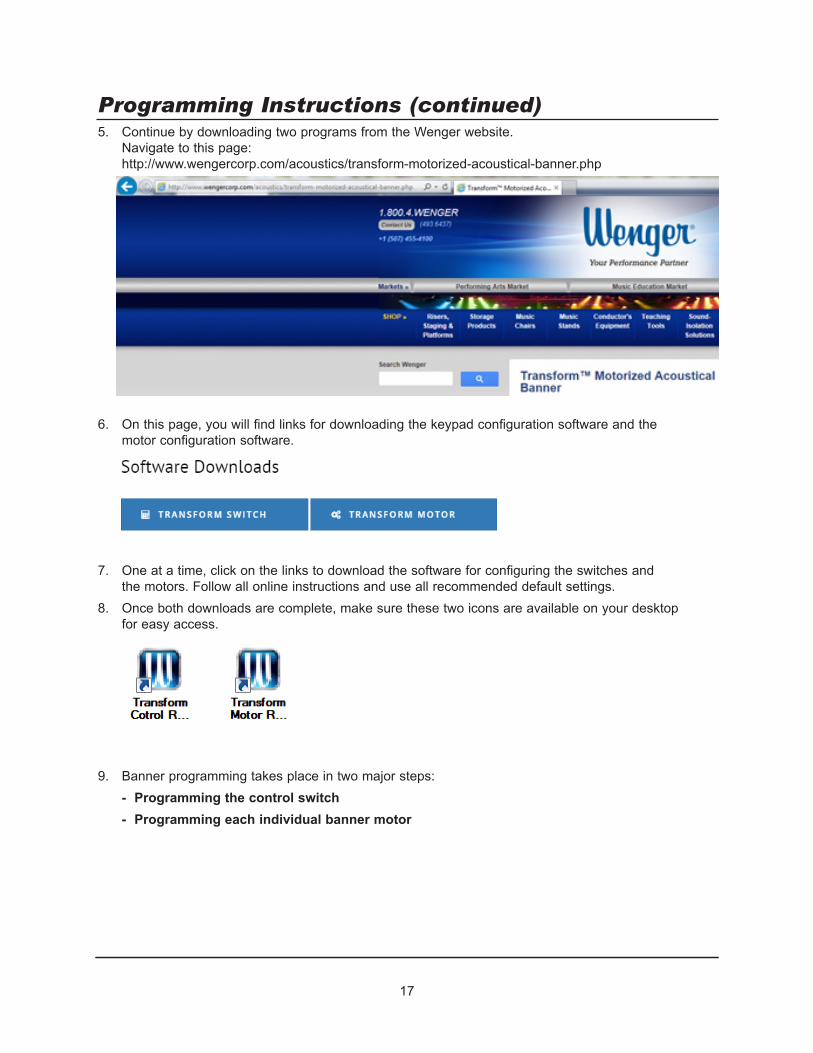
Programming Instructions (continued)5. Continue by downloading two programs from the Wenger website.
Navigate to this page: http://www.wengercorp.com/acoustics/transform-motorized-acoustical-banner.php
6. On this page, you will find links for downloading the keypad configuration software and the motor configuration software.
7. One at a time, click on the links to download the software for configuring the switches and the motors. Follow all online instructions and use all recommended default settings.
8. Once both downloads are complete, make sure these two icons are available on your desktop for easy access.
9. Banner programming takes place in two major steps: - Programming the control switch- Programming each individual banner motor

18
Programming Instructions (continued)Programming the Control Switch1. Connect your computer’s USB port to your banner network (or the individual switch)
as shown in the diagram below. The switch can be programmed either by itself or when installed in the banner network.
2. Open the Switch Configuration Tool by double-clicking on this icon on your computer.
3. This screen should be visible.

19
Programming Instructions (continued)Programming the Control Switch (continued)4. Connect your computer to the network.
Identify the Com port used by your system and select it in the drop down box. In this case, the active port was COM4.
5. Click on “Connect”. A green COM Port Open message indicates that the program is in control of this COM port.
6. Switches are referred to by their position in numerical order from top to bottom. Switch 1 is the top button. Switch 7 and Switch 8 are the two buttons in the bottom row. (Switch 8 is the one on the right.)
For the 8-button switch, all switches are active and programmable. For the 6-button switch, although they are shown in the programming screen,
switches 4 and 5 do not have physical pushbuttons associated with them. The bottom three switches are switches 6,7 and 8 (just like on the 8 button version).
8-Button Switch
6-Button Switch

20
Programming Instructions (continued)Programming the Control Switch (continued)7. For this example, the switch will be programmed to operate all three banners simultaneously
using the 8-button switch. (The 6-button switch would program identically except Presets 4 and 5 would not be available.)
8. A typical application will probably have one preset where all banners are all the way up in their retracted position. Similarly, another preset would be where all banners are fully deployed (down). For this example we will use Preset 1 for all banners fully UP and Preset 5 for all banners fully DOWN.
9. The down arrow simply jogs all banners downward simultaneously until you release the button. The up arrow does the same thing in the upward direction. The STOP button will instantaneously stop any banner that is in motion.
10. The other three presets can be used to customize your environment. The numbers selected
for this example are purely random. Your actual banner positions will be dictated by the acoustical and physical needs of the venue. For example, you may have a need for maximum acoustical absorption but certain banners may be in the way of a projection screen or some other physical obstruction. Those banners could be set to remain fully up or just partially down. Another example would be dictated by acousticians that wish to tune the room for specific types of events. Presets might be set up specifically for the differing needs of instrumental, choral and theatrical productions.
11. The exact position of each preset is actually stored in the motors, not in this switch. This switch just needs to be programmed to tell each motor what you want it to do.
12. Set up each of the 8 switch boxes as shown below. Make sure that all dropdowns, IP values, selection buttons and check boxes are set as shown.
NOTE: You will see that there are many options for each button position. This example shows a very simple system with only one switch controlling all banners in the network. This is probably sufficient for most applications. Advanced users can add sophistication as necessary for their specific application.

21
Programming Instructions (continued)Programming the Control Switch (continued)13. In the upper box, enter the switch address 000002 (or other hexadecimal address)
in the box as shown. Press “Set Group All Address”.
14. Press “Set Config”. This will save all values to the switch.
15. To make sure that the data was transferred correctly, press “Clear Data Field”. This will erase the data in the displays (only).
16. Now click on “Get Config” to retrieve and display the saved data. This should recall your original program parameters.
17. Make sure that all recalled entries are still correct. 18. Close the program.
(Note that both the switch configuration and motor configuration tools cannot be open on the same Com port.)

22
Programming Instructions (continued)Programming the Control Switch (continued)Switch Functionality19. If all the above steps are performed correctly (and AFTER the banner motors are properly
configured), the switch will perform as follows (but only after the banner motors are programmed in the next section):
Preset 1 Fully retracted - Banners fully raised to the upper limits with a momentary button actuation.
Preset 2 Banners adjusted to a custom mid-position with a momentary button actuation.Preset 3 Banners adjusted to a custom mid-position with a momentary button actuation.Preset 4 Banners adjusted to a custom mid-position with a momentary button actuation.Preset 5 Fully deployed - Banners fully lowered to the lower limits with a momentary button
actuation.Stop Immediate stop of any motion upon pressing this button.Down Arrow Extend all banners downward for as long as the button is held until the down limit
is reached.Up Arrow Retract all banners upward for as long as the button is held until the up limit is
reached.
Programming Shortcut(Most simple applications can take advantage of this shortcut!)If all buttons on all switches on any particular network are to control all of the banners simultaneously, the switches can be programmed to control all motors without the need to identify the motor addresses or groups on the network.
This should allow all banners on the network to be operated up or down within their factory set limits without the need to complete any of the following procedures for “Programming the Banner Motors”. The limits must be readjusted using a Limit Setting Tool (see page 32).
Individual motor programming will then be required only if individual upper and lower limit adjustments are necessary or if any intermediate positions are desired. Even if individual motor programming is required, “Programming the Banner Motors” steps 15 and 16 can be skipped where a group number is assigned to every motor on the network if the switch is set up in this manner.
This is accomplished using the following settings for each control on the network regardless of the individual switch function selected.
1. Click the “Motor All” for all eight switches
2. Type the address “FFFFFF” in the “Motor All Address” box.
3. Click “Set Config” to save.4. This switch will now control
all banners found on the network.

23
Programming Instructions (continued)Programming the Banner MotorsThe entire banner networked must now be installed and connected. Individual motors can be selected and programmed using the motor configuration software.
1. Open the Motor Configuration tool by double-clicking on this icon (downloaded earlier).
2. This screen should be visible.
3. Identify the Com port used by your system and select it in the drop down box. In this case, COM4 is used.

24
Programming Instructions (continued)Programming the Banner Motors (continued)4. Click on “Connect”.
A Disconnect selection will replace Connect and a green “COM Port Open” message displayed at the bottom of the screen indicates that the program is in control of that COM port.
5. Identify all the motor addresses present on the network by clicking on the “Auto Discovery” button.
6. You will be prompted to fill in the approximate number of motors in the network. (In this limited size example, we used only 3.) Enter that number and press OK.
7. The software will find and list all of the motor addresses present in the network. They will be listed on the right hand side of the screen (in no particular order).

25
Programming Instructions (continued)Programming the Banner Motors (continued)8. For our example, we are using the 8-Button switch.
We are going to set up 3 intermediate positions in addition to fully up and fully down for each of the 3 motors.
At this point it is advisable to build a chart or spreadsheet to keep track which banner motor is in what position in the facility and what position it is to be set at for each of the presets. The percentages shown are percent in the down direction and can be any value from 1 to 99. (1% is nearly up and 99% is nearly down.)
9. The banner motor’s address is labeled on the motor end of the banner assembly. If these were not recorded before the banners were hung, it is probably easiest to use the software to identify which address goes with which banner rather than climbing up to attempt to read the label. Type or copy one of the motor addresses from the list on the right into the “Addressing” field on the left. Click on “Single”.
10. Click on the “Reset Motor” button in the Adjust Limits box. After clicking OK in any warning boxes, the “Wink Motor” selection will become active. Click on it.

26
Programming Instructions (continued)Programming the Banner Motors (continued)11. The banner whose motor address was entered in the “Single” box will briefly cycle
a few inches down and then back up again. This gives you a visual indication of which banner owns this motor address.
Record all the motor addresses in the chart in the same manner. (Be careful not to click on any other buttons to avoid unintentional changes to the motor settings).
12. The first step in the motor setup process is verifying that the UP and DOWN limits set at the factory are appropriate now that the banner is installed.
Go to the “Movements” box on the left side of the screen and alternately click on the “Up Limit” and “Down Limit” buttons. Watch as that banner cycles to its fully up and down positions to make sure that those limits are set appropriately.
Note: These motors are extremely compact and have a limited duty cycle. They can run for about 5-10 minutes continuously before reaching their thermal limit. The motor will cease to operate until the motor cools and automatically resets. (The motor will not restart until another command is received after the thermal reset.) While this will not harm the motor, it may add time to the overall installation due to the waiting time required to allow the motor to cool down. Avoid any unnecessary banner movements during installation.

27
Programming Instructions (continued)Programming the Banner Motors (continued)13 If limit adjustment is necessary, go to the “Adjust Limits” box on
the right side of the screen and check the “Limit Adjust” box. Note that is best to first have the banner at one of its limits to
achieve the full functionality of this menu. Read and click OK on any warnings as you enter this menu.
14. There are numerous ways to adjust the limits. One of the simplest is to jog the motor a certain number of pulses.
Ten (10 pulses/milliseconds is a good value for fine tuning once you near the final limit location. (Larger pulse counts can be entered if there is a longer distance to be traveled.)
To begin, enter 10 in the boxes as shown below and press the appropriate “Up (Pulses)” or “Down (Pulses)” button.
Monitor how much the banner moves each time and adjust the value in the box as necessary to zero in on the final desired position.
Repeat for the opposite limit as necessary.
15. All of the motors controlled by a single switch need to be “grouped”. To assign a group number, first erase any group assignments that may already reside in the motor.
Press the “Erase Groups” button.
16. Enter the group number. Here we are using group 000002. (This always needs to be a six digit, hexidecimal number and must match the group number programmed into the switch.)
Click on “Set Groups” to save.

28
Programming Instructions (continued)Programming the Banner Motors (continued)17. Most applications will have an “All Banners UP” and “All Banners DOWN” position
so it makes sense to use the top preset button (Preset 1) for the UP preset and the bottom preset button (Preset 5) for the DOWN preset.
The remaining presets 2, 3 and 4 (or only Preset 2 in the 6-button version of the switch) can be customized in nearly infinite ways. Using the procedure below, each motor will be “taught” where to position itself for each of the 3 presets. (The intermediate positions in this example are purely hypothetical.)
During switch programming, it was already established that Presets 1 and 5 were the upper and lower limits of the banner that have already been established. Only presets 2, 3 and 4 remain to be taught to the motor.
18. For initial setup, it is probably easiest to use the “% Down” method to establish the preset positions. That process will be followed in the instructions below. (For final tuning where exact positioning is required, other setting methods are available including simply adjusting the banner to the desired position and identifying that position as the preset.)
Refer to the table used to keep track of the motor address. 19. Start by establishing that the switch Preset 2 for banner 1 adjusts the banner to
85% down from the address chart. Enter 2 in the IP# box and 85 in the IP% box. Click on the Set IP# @ IP% button. The software calculates the number of pluses down
from the Up position for the banner to be deployed 85% down. In this case, that value was 366 and is automatically entered in the IP02 box.

29
Programming Instructions (continued)Programming the Banner Motors (continued)20. According to the chart, Intermediate Position 3 for this
motor is to be 25% down. Enter 3 in the IP# box and 25 in the IP% box. Click on the “Set IP# @ IP%” button.
The software calculates the number of pluses down from the Up position for the banner to be deployed 25% down. In this case, that value was 118 and is automatically entered in the IP02 box.
21. Repeat this process once again to set IP #4 to 66% down.
22. With the software still set up to control a single motor (0A5359 in this case), operate this motor to check your settings. Verify that the banner is at its Up limit by pressing the up limit button. If the banner was not fully up before, it should advance to the up position.
Press the “Next IP Down” button. The banner should move to the next Intermediate Position down. Pressing it again will send it to the next intermediate position down.
(Note that this happens in order of the position pulse counts and NOT in the order of the IP number.)
30
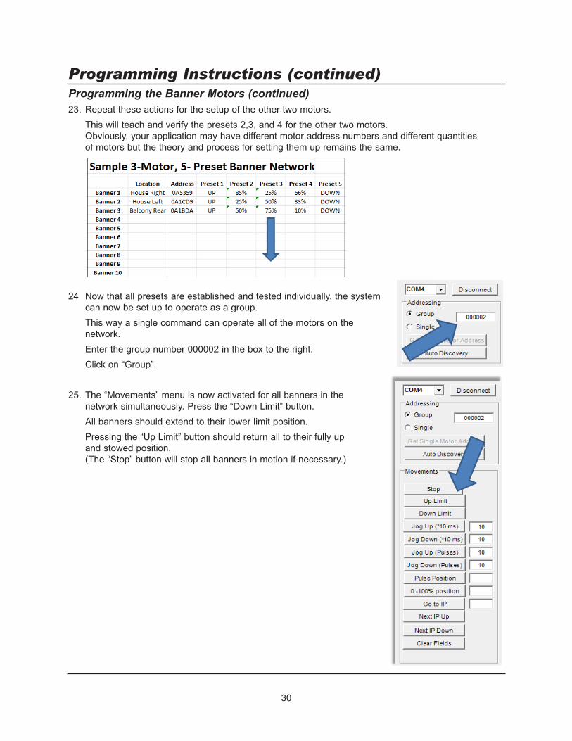
Programming Instructions (continued)Programming the Banner Motors (continued)23. Repeat these actions for the setup of the other two motors. This will teach and verify the presets 2,3, and 4 for the other two motors.
Obviously, your application may have different motor address numbers and different quantities of motors but the theory and process for setting them up remains the same.
24 Now that all presets are established and tested individually, the system can now be set up to operate as a group.
This way a single command can operate all of the motors on the network.
Enter the group number 000002 in the box to the right. Click on “Group”. 25. The “Movements” menu is now activated for all banners in the
network simultaneously. Press the “Down Limit” button. All banners should extend to their lower limit position. Pressing the “Up Limit” button should return all to their fully up
and stowed position. (The “Stop” button will stop all banners in motion if necessary.)

31
Programming Instructions (continued)Programming the Banner Motors (continued)26. Entering 2 in the box to the right of the “Go To IP” button and then clicking
on the “Go To IP” button will send all banners to Intermediate Position 2 set earlier in this process.
Test Intermediate Positions 3 and 4 for the same functionality.
Testing System Operation1. The final test is to make sure that the wall switch operates the system correctly.
When the switch was programmed, Presets 1 was defined as the Up Limit. Pressing that button should cause all banners to retract fully.
Similarly, pressing Preset 5 should cause all banners to lower to their fully down position.
2. Pressing Presets 2,3 and 4 should immediately send each banner to that predefined position from wherever it happens to be.
3. Setup in now complete. It is recommended that all final values be recorded permanently for future reference.

32
Cleaning Laminate SurfacesUse a soft, damp cloth to clean all laminate surfaces. For smudges or fingerprints, dampen a cloth with any standard non-abrasive household cleaner and wipe clean.
Cleaning FabricUse a soft, damp cloth to clean or use a fabric cleaner. Never hose down or soak the fabric.
Mechanical CheckCheck for loose or damaged parts and for loose fasteners annually. Replace or repair damaged parts promptly. Refer to the Replacement Parts List.
Maintenance
Drapery Replacement and TrackingEach banner assembly is adjusted at the factory for proper “tracking”. Tracking is the assembly’s ability to position the fabric panels directly on top of one another as the drum revolves and the banner rolls up into its stored position.
Accurate, repeatable tracking is critical to proper banner operation. Tracking not only affects the position of the banner but also affects the levelness of the bottom batten, an issue critical to appearance. Banner installation accuracy, stretching, variations in fabric manufacture and changes in temperature/humidity can all affect how well the banner tracks.
If tracking adjustment is required, contact Wenger directly.
Limit Setting Tool (Optional)Wenger offers a Limit Setting Tool that can ease basic maintenance procedures in some instances.
This tool connects directly to an individual banner that has been disconnected from the banner network. It can reset upper and lower limits as well as intermediate positions without the need to connect a laptop to the network. However, each banner’s communication cable must be individually accessible after installation (via a catwalk or other simple means) which is often not the case.
The Limit Setting Tool is Wenger part number 213A168. Please contact Wenger to see if this tool would be an advantage for maintaining your system.