installation instructions - sunbrite tv · installation instructions sb-wm46na 7 concrete...
TRANSCRIPT

I N S T A L L A T I O N I N S T R U C T I O N S
Instrucciones de instalaciónInstallationsanleitungInstruções de Instalação
Istruzioni di installazioneInstallatie-instructiesInstructions d´installation
(with short uprights)(with long uprights)
Outdoor Non-Articulating Wall MountSpanish Product DescriptionGerman Product Description
Portuguese Product Description Italian Product DescriptionDutch Product Description
French Product Description
SB-WM46NA

SB-WM46NA Installation Instructions
2
DISCLAIMERSunBriteTV LLC (SBTV) intend to make this manual accurateand complete. However, SBTV makes no claim that theinformation contained herein covers all details, conditions orvariations, nor does it provide for every possible contingency inconnection with the installation or use of this product. Theinformation contained in this document is subject to changewithout notice or obligation of any kind. SBTV makes norepresentation of warranty, expressed or implied, regarding theinformation contained herein. SBTV assumes no responsibilityfor accuracy, completeness or sufficiency of the informationcontained in this document.
SunBriteTV® is a registered trademark of SunBrite TV LLC.Built to SunBriteTV® specifications by Chief Manufacturing. Allrights reserved.
DEFINITIONSMOUNTING SYSTEM: A MOUNTING SYSTEM is theprimary Chief product to which an accessory and/or componentis attached.
ACCESSORY: AN ACCESSORY is the secondary Chiefproduct which is attached to a primary Chief product, and mayhave a component attached or setting on it.
COMPONENT: A COMPONENT is an audiovisual itemdesigned to be attached or resting on an accessory or mountingsystem such as a video camera, CPU, screen, display,projector, etc.
WARNING: A WARNING alerts you to the possibility ofserious injury or death if you do not follow the instructions.
CAUTION: A CAUTION alerts you to the possibility ofdamage or destruction of equipment if you do not follow thecorresponding instructions.
IMPORTANT SAFETY INSTRUCTIONS
WARNING: Failure to read, thoroughly understand, andfollow all instructions can result in serious personal injury,damage to equipment, or voiding of factory warranty! It is theinstaller’s responsibility to make sure all mounting systems/accessories are properly assembled and installed using theinstructions provided.
WARNING: Failure to provide adequate structural strengthfor this mounting system can result in serious personal injuryor damage to equipment! It is the installer’s responsibility tomake sure the structure to which this mounting system isattached can support five times the combined weight of allequipment. Reinforce the structure as required beforeinstalling the component.
WARNING: Exceeding the weight capacity can result inserious personal injury or damage to equipment! It is theinstaller’s responsibility to make sure the combined weight ofall components attached to the SB-WM46NA up to (andincluding) the display does not exceed 175 lbs (80 kg).
WARNING: Use this mounting system only for its intendeduse as described in these instructions. Do not useattachments not recommended by the manufacturer.
WARNING: Never operate this mounting system if it isdamaged. Return the mounting system to a service center forexamination and repair.
IMPORTANT ! : The SB-WM46NA mounts are designed to bemounted to a 2" x 4" wood studs (16" or 24" on center) wall witha maximum covering of 5/8" thick drywall, plywood, OSB,fiberboard, buffalo board or other similar sheathing materials.IMPORTANT ! : The SB-WM46NA mounts may be installedto a bare 8" concrete wall (16" or 24" on center) if 5/16 x 3"Buildex® Tapcon® anchors with Blue Climaseal® coating (notincluded) are used in place of lag bolts (W) provided.
--SAVE THESE INSTRUCTIONS--

Installation Instructions SB-WM46NA
3
DIMENSIONS
.7920
(10X)
15 TILT

SB-WM46NA Installation Instructions
4
LEGEND
Tighten Fastener
Apretar elemento de fijación
Befestigungsteil festziehen
Apertar fixador
Serrare il fissaggio
Bevestiging vastdraaien
Serrez les fixations
Loosen Fastener
Aflojar elemento de fijación
Befestigungsteil lösen
Desapertar fixador
Allentare il fissaggio
Bevestiging losdraaien
Desserrez les fixations
Phillips Screwdriver
Destornillador Phillips
Kreuzschlitzschraubendreher
Chave de fendas Phillips
Cacciavite a stella
Kruiskopschroevendraaier
Tournevis à pointe cruciforme
Open-Ended Wrench
Llave de boca
Gabelschlüssel
Chave de bocas
Chiave a punte aperte
Steeksleutel
Clé à fourche
By Hand
A mano
Von Hand
Com a mão
A mano
Met de hand
À la main
Hex-Head Wrench
Llave de cabeza hexagonal
Sechskantschlüssel
Chave de cabeça sextavada
Chiave esagonale
Zeskantsleutel
Clé à tête hexagonale
Pencil Mark
Marcar con lápiz
Stiftmarkierung
Marcar com lápis
Segno a matita
Potloodmerkteken
Marquage au crayon
Drill Hole
Perforar
Bohrloch
Fazer furo
Praticare un foro
Gat boren
Percez un trou
Adjust
Ajustar
Einstellen
Ajustar
Regolare
Afstellen
Ajuster
Remove
Quitar
Entfernen
Remover
Rimuovere
Verwijderen
Retirez
Optional
Opcional
Optional
Opcional
Opzionale
Optie
En option
Security Wrench
Llave de seguridad
Sicherheitsschlüssel
Chave de segurança
Chiave di sicurezza
Veiligheidssleutel
Clé de sécurité

Installation Instructions SB-WM46NA
5
TOOLS REQUIRED FOR INSTALLATION
PARTS
#21/2" (12.7mm) -wood stud7/32" - wood stud3/8" (9.5mm) - concrete1/4" - concrete
A (1)[wall plate]
B (1)[left interface bracket - short]
[right interface bracket - short]C (1)
W (4)5/16 x 3 1/2”
X (4)5/16”
F (4)M8 x 20mm
G (4)M8 x 30mm
H (4)M6 x 16mm
J (4)M6 x 25mm
K (4)M5 x 16mm
L (4)M5 x 20mm
M (4)M5 x 25mm
N (4)M4 x 16mm
P (4)M4 x 20mm
Q (4)M4 x 25mm
R (4) T (4) U (4)#10
V (4)1/4”
5/16 x 3" Buildex Tapcon® anchors
(not included)with Blue Climaseal® coating
D (2)[interface bracket - long]
6.40mm12.7mm

SB-WM46NA Installation Instructions
6
ASSEMBLY and INSTALLATIONINSPECT MOUNT BEFORE ASSEMBLY
1. Carefully inspect the mount components for shippingdamage.
2. If any damage is apparent, call your carrier claims agentand do not continue with the installation until the carrier hasreviewed the damage.
NOTE: Read all assembly instructions before starting theinstallation process.
Wall Plate InstallationIMPORTANT ! : The SB-WM46NA mounts are designed to bemounted to a 2" x 4" wood studs (16" or 24" on center) wall witha maximum covering of 5/8" thick drywall, plywood, OSB,fiberboard, buffalo board or other similar sheathing materials.IMPORTANT ! : The SB-WM46NA mounts may be installedto a bare 8" concrete wall (16" or 24" on center) if 5/16 x 3"Buildex® Tapcon® anchors with Blue Climaseal® coating (notincluded) are used in place of lag bolts (W) provided.
Wood Stud Installation
WARNING: It is the responsibility of the installer to verifythat the structure to which the mount is anchored will safelysupport five times the combined load of all attachedcomponents and equipment.
1. Determine a suitable mounting location and lift the wall plate(A) into mounting position on wall.
2. Using a small nail or screw (not provided) in the center hole,lightly support the wall plate at the mounting location. (SeeFigure 1)
3. Level the wall plate (A) and drill 7/32” pilot holes foranchoring the wall plate. Holes must be drilled at the centerof wood studs. (See Figure 1) or (See Figure 2)
4. Using four 5/16 x 3 1/2” lag bolts (W) and four 5/16” washers(X), install the wall plate (A) on the wall. (See Figure 1) or(See Figure 2)
Figure 1
Figure 2
5. Slide the latches out on the wall mount in preparation forinstalling display. (See Figure 3)
Figure 316" studs installation
(W) x 443
7/32”
(X) x 4
x 4
(A)
(W) x 44
3
7/32"
(X) x 4
x 4
24" studs installation
(A)
5
5
Installation Instructions SB-WM46NA
7
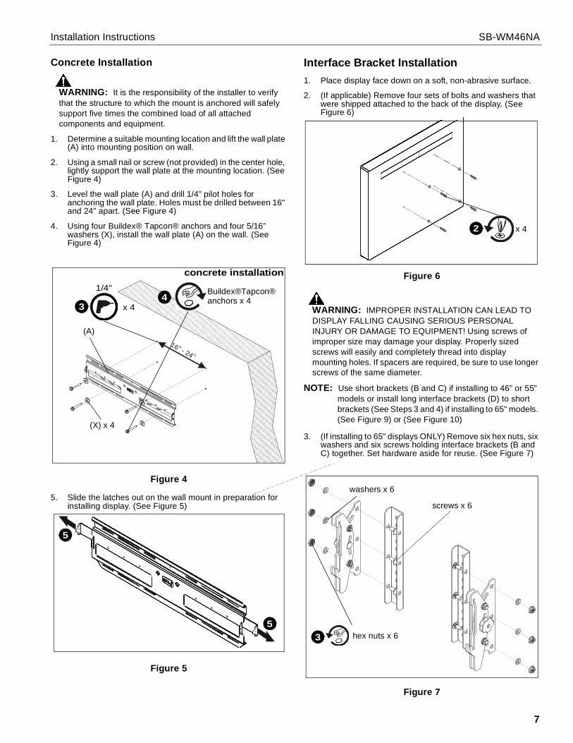
Concrete Installation
WARNING: It is the responsibility of the installer to verifythat the structure to which the mount is anchored will safelysupport five times the combined load of all attachedcomponents and equipment.
1. Determine a suitable mounting location and lift the wall plate(A) into mounting position on wall.
2. Using a small nail or screw (not provided) in the center hole,lightly support the wall plate at the mounting location. (SeeFigure 4)
3. Level the wall plate (A) and drill 1/4" pilot holes foranchoring the wall plate. Holes must be drilled between 16"and 24" apart. (See Figure 4)
4. Using four Buildex® Tapcon® anchors and four 5/16”washers (X), install the wall plate (A) on the wall. (SeeFigure 4)
Figure 4
5. Slide the latches out on the wall mount in preparation forinstalling display. (See Figure 5)
Figure 5
Interface Bracket Installation1. Place display face down on a soft, non-abrasive surface.
2. (If applicable) Remove four sets of bolts and washers thatwere shipped attached to the back of the display. (SeeFigure 6)
Figure 6
WARNING: IMPROPER INSTALLATION CAN LEAD TODISPLAY FALLING CAUSING SERIOUS PERSONALINJURY OR DAMAGE TO EQUIPMENT! Using screws ofimproper size may damage your display. Properly sizedscrews will easily and completely thread into displaymounting holes. If spacers are required, be sure to use longerscrews of the same diameter.
NOTE: Use short brackets (B and C) if installing to 46" or 55"models or install long interface brackets (D) to shortbrackets (See Steps 3 and 4) if installing to 65" models.(See Figure 9) or (See Figure 10)
3. (If installing to 65" displays ONLY) Remove six hex nuts, sixwashers and six screws holding interface brackets (B andC) together. Set hardware aside for reuse. (See Figure 7)
Figure 7
16” - 24”
concrete installation
3
1/4"
x 4
(X) x 4
(A)
Buildex®Tapcon®4 anchors x 4
5
5
2 x 4
hex nuts x 63
screws x 6
washers x 6

SB-WM46NA Installation Instructions
8
4. (If installing to 65" displays ONLY) Use six removed hexnuts, six removed washers and six removed screws toassemble two long interface brackets (D) to remaining tiltassembly. (See Figure 8)
Figure 8
5. Place left and right interface brackets (B and C) or (D x 2)on the back of the display, with the tension knob on eachbracket facing toward the outside of the television. (SeeFigure 9) or (See Figure 10)
NOTE: Spacers (R and T) are used to offset the bracket if themounting holes are recessed or to get around theprotrusions.
6. Secure the left and right interface bracket assemblies (Band C) or (D x 2) to the display. Select the mountinghardware that fits your application. (See Figure 9)
• Use spacers (R or T), if necessary.• Use M6 screws (H or J) or M8 screws (F or G), and
1/4" washers (V).• Or, use M4 screws (N, P or Q) or M5 screws (K, L or
M), 1/4" washers (V) and #10 washers (U).
Figure 9
Figure 10
(D) x 2
4
screws x 6
tilt assembly
hex nuts x 6washers x 6
4 (F-Q) x 4
(V) x 4(R or T) x 4(if necessary) (46" or 55" models)
(B)
(C)
(w/M4 and M5screws ONLY)
(U) x 4
(65" models)
4 (F-Q) x 4
(U) x 4
(R or T) x 4(if necessary)
(D)
(D) x 2
(w/M4 and M5screws ONLY)
(V) x 4

Installation Instructions SB-WM46NA
9
Display Installation
WARNING: Exceeding the weight capacity can result inserious personal injury or damage to equipment! It is theinstaller’s responsibility to make sure the combined weight ofall components located between the SB-WM46NA up to (andincluding) the display does not exceed 175 lbs (80 kg).
1. Place the display on the wall plate (A) by hooking the hooksof the brackets (B and C) or (D and E) in the top of the wallplate. (See Figure 11)
2. Secure the display by sliding the latches, one on each side,inward. As the latches are slid in, it will lower and catch thebottom hook and secure the television in place. (See Figure11)
3. If desired, install self tapping screws (not provided) and/orpadlocks (not provided) for additional security. (See Figure11)
Figure 11
Tilt Adjustment1. Adjust tilt tension adjustment knobs to desired tension. (See
Figure 12)
2. Adjust tilt of display by pulling the top of display away fromthe wall until desired tilt position is reached. (See Figure 12)
3. Tighten tilt tension adjustment knobs to secure tilt position.(See Figure 12)
Figure 12
Display RemovalTo remove display:
CAUTION: Disconnect power and audio/video cablesbefore removing the display from its wall mount.
WARNING: The display is heavy and extremely fragile.Exercise caution when removing the display from the mountto avoid equipment damage or personal injury.
1. If applicable, remove the self tapping screws (not provided)and/or padlocks from both sides of the wall plate. Thishardware provides security. (See Figure 13)
2. Slide the security latches out on both sides to disengage thedisplay from the wall plate. (See Figure 13)
3. With an assistant, lift the display up and off the wall plate toremove the display from the wall. (See Figure 13)
Figure 13
x 2 (optional)3
3
1
1
2
2
(46" or 55" models shown)tilt adjustment knobs
2
2
(46" or 55" models shown)
x 213
2
2
(46" or 55" models sown)

SB-WM46NA Installation Instructions
10

Installation Instructions SB-WM46NA
11

SB-WM46NA Installation Instructions
8800-002841 Rev0104/17
SunBriteTV, LLC2001 Anchor CourtThousand Oaks, CA 91320866-357-8688www.sunbritetv.com