installation instructions shift improver kitintroduction note: the b&m th400 shift improver kit...
TRANSCRIPT
Rev. 1/10/2020
WORK SAFELY! For maximum safety, perform this installation on a clean, level surface and with the engine turned off. Place blocks or wedges in front of and behind both rear wheels to prevent movement in either direction.
CAUTION: To avoid any possibility of bodily injury or damage to vehicle, do not attempt installation until you are confident that the vehicle is safely secured and will not move.
IMPORTANT NOTICE
Technical Support (866) 464‐6553 1 www.bmracing.com
Installation Instructions SHIFT IMPROVER KIT
Fits 1988-1994 GM TH400/3L80, and TH475/3L80HD For specific vehicles, see “Applications” tab on this product’s webpage.
Part No. 20261
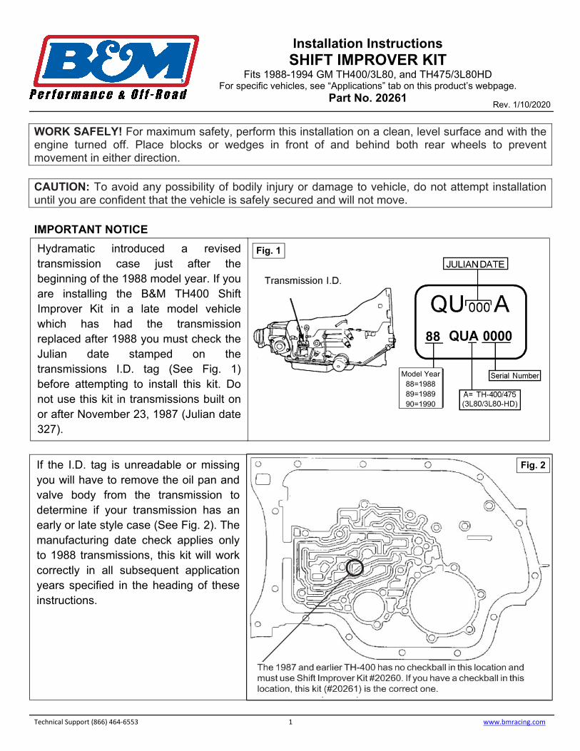
Hydramatic introduced a revised transmission case just after the beginning of the 1988 model year. If you are installing the B&M TH400 Shift Improver Kit in a late model vehicle which has had the transmission replaced after 1988 you must check the Julian date stamped on the transmissions I.D. tag (See Fig. 1) before attempting to install this kit. Do not use this kit in transmissions built on or after November 23, 1987 (Julian date 327).
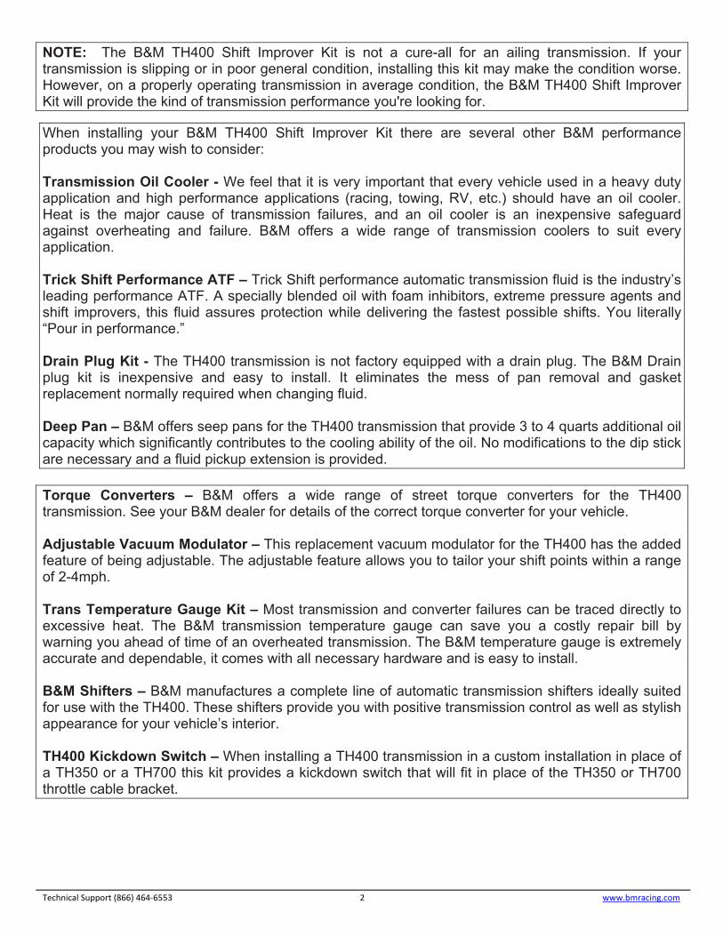
If the I.D. tag is unreadable or missing you will have to remove the oil pan and valve body from the transmission to determine if your transmission has an early or late style case (See Fig. 2). The manufacturing date check applies only to 1988 transmissions, this kit will work correctly in all subsequent application years specified in the heading of these instructions.
Fig. 1
Model Year 88=1988 89=1989 90=1990
Fig. 2
88
NOTE: The B&M TH400 Shift Improver Kit is not a cure-all for an ailing transmission. If your transmission is slipping or in poor general condition, installing this kit may make the condition worse. However, on a properly operating transmission in average condition, the B&M TH400 Shift Improver Kit will provide the kind of transmission performance you're looking for.
When installing your B&M TH400 Shift Improver Kit there are several other B&M performance products you may wish to consider:
Transmission Oil Cooler - We feel that it is very important that every vehicle used in a heavy duty application and high performance applications (racing, towing, RV, etc.) should have an oil cooler. Heat is the major cause of transmission failures, and an oil cooler is an inexpensive safeguard against overheating and failure. B&M offers a wide range of transmission coolers to suit every application.
Trick Shift Performance ATF – Trick Shift performance automatic transmission fluid is the industry’s leading performance ATF. A specially blended oil with foam inhibitors, extreme pressure agents and shift improvers, this fluid assures protection while delivering the fastest possible shifts. You literally “Pour in performance.”
Drain Plug Kit - The TH400 transmission is not factory equipped with a drain plug. The B&M Drain plug kit is inexpensive and easy to install. It eliminates the mess of pan removal and gasket replacement normally required when changing fluid.
Deep Pan – B&M offers seep pans for the TH400 transmission that provide 3 to 4 quarts additional oil capacity which significantly contributes to the cooling ability of the oil. No modifications to the dip stick are necessary and a fluid pickup extension is provided.
Torque Converters – B&M offers a wide range of street torque converters for the TH400 transmission. See your B&M dealer for details of the correct torque converter for your vehicle.
Adjustable Vacuum Modulator – This replacement vacuum modulator for the TH400 has the added feature of being adjustable. The adjustable feature allows you to tailor your shift points within a range of 2-4mph.
Trans Temperature Gauge Kit – Most transmission and converter failures can be traced directly to excessive heat. The B&M transmission temperature gauge can save you a costly repair bill by warning you ahead of time of an overheated transmission. The B&M temperature gauge is extremely accurate and dependable, it comes with all necessary hardware and is easy to install.
B&M Shifters – B&M manufactures a complete line of automatic transmission shifters ideally suited for use with the TH400. These shifters provide you with positive transmission control as well as stylish appearance for your vehicle’s interior.
TH400 Kickdown Switch – When installing a TH400 transmission in a custom installation in place of a TH350 or a TH700 this kit provides a kickdown switch that will fit in place of the TH350 or TH700 throttle cable bracket.
Technical Support (866) 464‐6553 2 www.bmracing.com
INTRODUCTION NOTE: The B&M TH400 Shift Improver Kit can be installed in a few hours by carefully following instructions. Transmission components are precision fit parts. Burrs and dirt are the number one enemies of an automatic transmission. Cleanliness is very important, so a clean work area or bench is necessary. We suggest a clean work bench top from which oil can easily be cleaned or a large piece of cardboard.
This kit contains all parts necessary to obtain three levels of performance depending on intended use: Heavy Duty: For towing, campers, motorhomes and 4-wheel drive vehicles. Heavy Duty level is a good starting place for light weight, high powered vehicles such as street rods. Heavy Duty level produces firm noticeable shifts.
Street: Dual purpose performance vehicles, street and strip performance cars and off road vehicles. Street level produces very firm, positive shifts.
DISASSEMBLY Automatic transmissions operate at temperatures between 180°F and 240°F. We recommend that the vehicle be allowed to cool for several hours before attempting disassembly to avid serious burns from hot oil and parts. CAUTION: MAKE SURE THE VEHICLE IS RIGIDLY AND SECURELY SUPPORTED, JACKSTANDS, WHEEL RAMPS OR A HOIST WORK BEST. DO NOT USE JACKS ALONE.
1. Have an oil drain pan ready to catch oil and a clean tray on which to put small parts so they won’tget lost or dirty. Drain the oil by removing the rear pan bolts and work towards the front leaving thetwo front bolts in place. If the pan is stuck to the case pry the pan loose with a screw driver. Slowlyremove the remaining two front bolts allowing the rest of the fluid to drain.
Technical Support (866) 464‐6553 3 www.bmracing.com
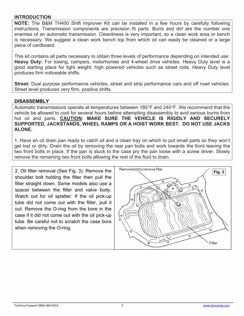
2. Oil filter removal (See Fig. 3): Remove theshoulder bolt holding the filter then pull thefilter straight down. Some models also use aspacer between the filter and valve body.Watch out for oil splatter. If the oil pick-uptube did not come out with the filter, pull itout. Remove the O-ring from the bore in thecase if it did not come out with the oil pick-uptube. Be careful not to scratch the case borewhen removing the O-ring.
Fig. 3
Technical Support (866) 464‐6553 4 www.bmracing.com
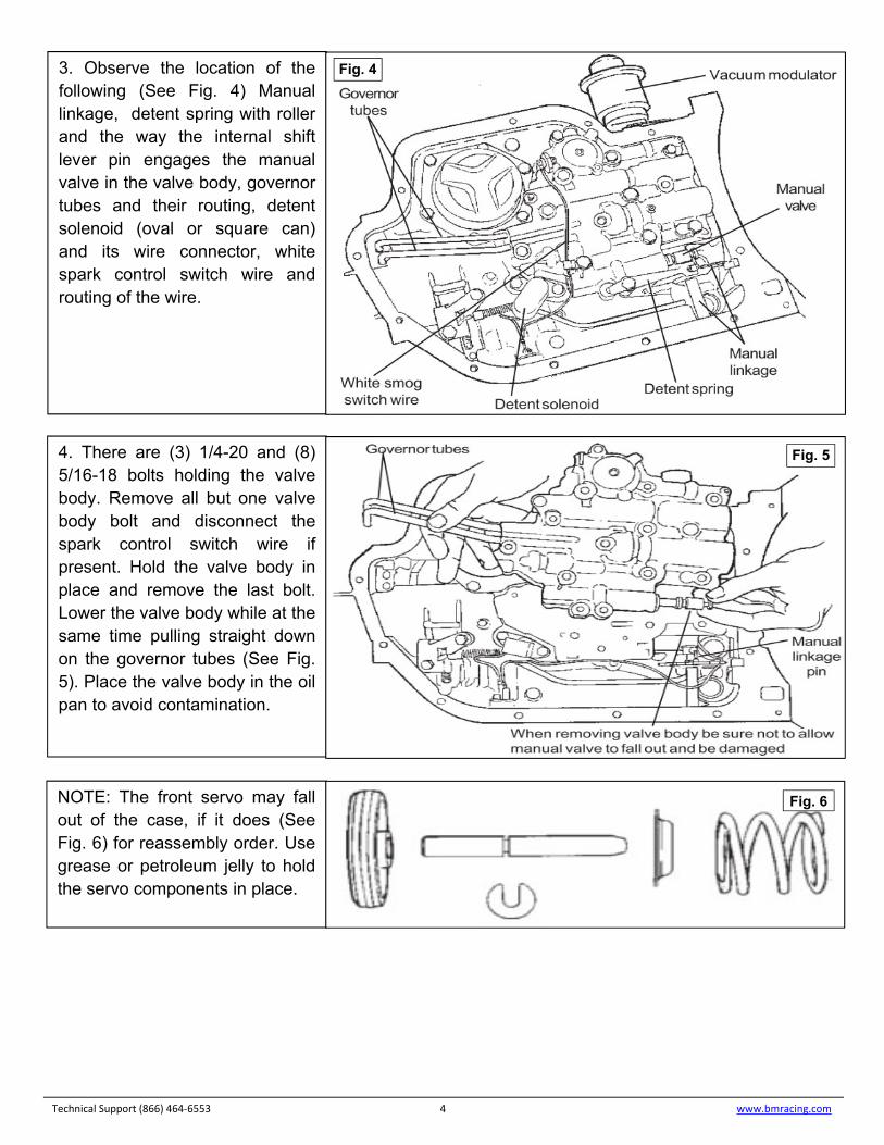
3. Observe the location of thefollowing (See Fig. 4) Manuallinkage, detent spring with rollerand the way the internal shiftlever pin engages the manualvalve in the valve body, governortubes and their routing, detentsolenoid (oval or square can)and its wire connector, whitespark control switch wire androuting of the wire.
4. There are (3) 1/4-20 and (8)5/16-18 bolts holding the valvebody. Remove all but one valvebody bolt and disconnect thespark control switch wire ifpresent. Hold the valve body inplace and remove the last bolt.Lower the valve body while at thesame time pulling straight downon the governor tubes (See Fig.5). Place the valve body in the oilpan to avoid contamination.
NOTE: The front servo may fall out of the case, if it does (See Fig. 6) for reassembly order. Use grease or petroleum jelly to hold the servo components in place.
Fig. 4
Fig. 5
Fig. 6
MODIFICATIONS
Technical Support (866) 464‐6553 5 www.bmracing.com
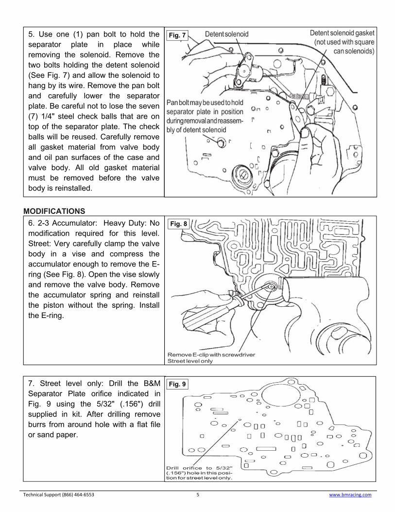
5. Use one (1) pan bolt to hold theseparator plate in place whileremoving the solenoid. Remove thetwo bolts holding the detent solenoid(See Fig. 7) and allow the solenoid tohang by its wire. Remove the pan boltand carefully lower the separatorplate. Be careful not to lose the seven(7) 1/4" steel check balls that are ontop of the separator plate. The checkballs will be reused. Carefully removeall gasket material from valve bodyand oil pan surfaces of the case andvalve body. All old gasket materialmust be removed before the valvebody is reinstalled.
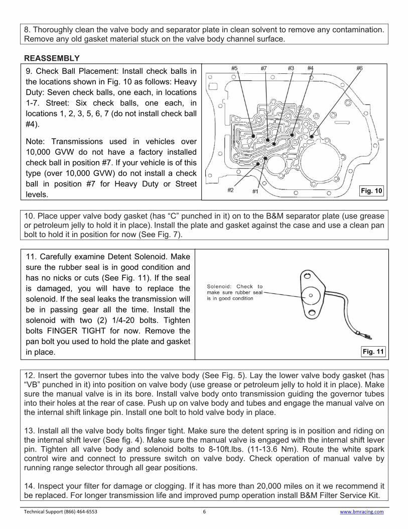
6. 2-3 Accumulator: Heavy Duty: Nomodification required for this level.Street: Very carefully clamp the valvebody in a vise and compress theaccumulator enough to remove the E-ring (See Fig. 8). Open the vise slowlyand remove the valve body. Removethe accumulator spring and reinstallthe piston without the spring. Installthe E-ring.
Fig. 8
Fig. 7
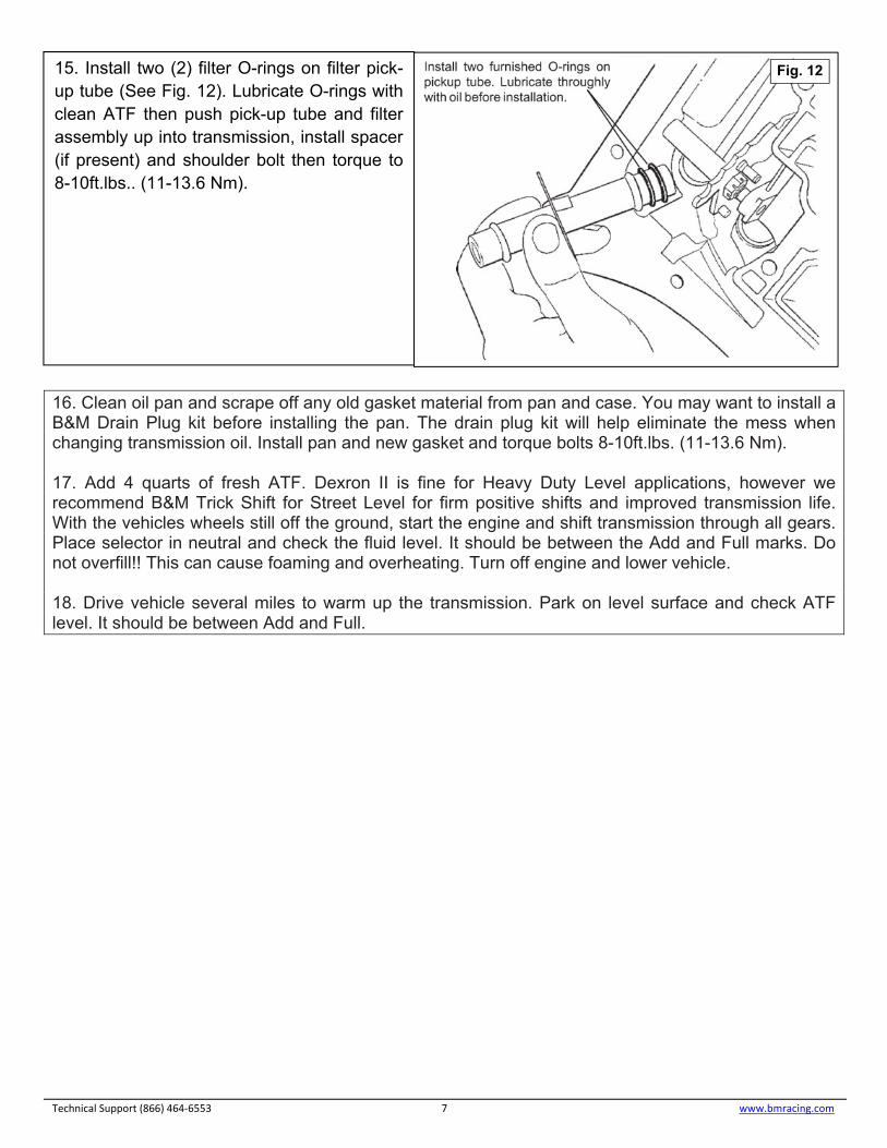
7. Street level only: Drill the B&MSeparator Plate orifice indicated inFig. 9 using the 5/32" (.156") drillsupplied in kit. After drilling removeburrs from around hole with a flat fileor sand paper.
Fig. 9
8. Thoroughly clean the valve body and separator plate in clean solvent to remove any contamination.Remove any old gasket material stuck on the valve body channel surface.
REASSEMBLY
10. Place upper valve body gasket (has “C” punched in it) on to the B&M separator plate (use greaseor petroleum jelly to hold it in place). Install the plate and gasket against the case and use a clean panbolt to hold it in position for now (See Fig. 7).
12. Insert the governor tubes into the valve body (See Fig. 5). Lay the lower valve body gasket (has“VB” punched in it) into position on valve body (use grease or petroleum jelly to hold it in place). Makesure the manual valve is in its bore. Install valve body onto transmission guiding the governor tubesinto their holes at the rear of case. Push up on valve body and tubes and engage the manual valve onthe internal shift linkage pin. Install one bolt to hold valve body in place.
13. Install all the valve body bolts finger tight. Make sure the detent spring is in position and riding onthe internal shift lever (See fig. 4). Make sure the manual valve is engaged with the internal shift leverpin. Tighten all valve body and solenoid bolts to 8-10ft.lbs. (11-13.6 Nm). Route the white sparkcontrol wire and connect to pressure switch on valve body. Check operation of manual valve byrunning range selector through all gear positions.
14. Inspect your filter for damage or clogging. If it has more than 20,000 miles on it we recommend itbe replaced. For longer transmission life and improved pump operation install B&M Filter Service Kit.
Technical Support (866) 464‐6553 6 www.bmracing.com
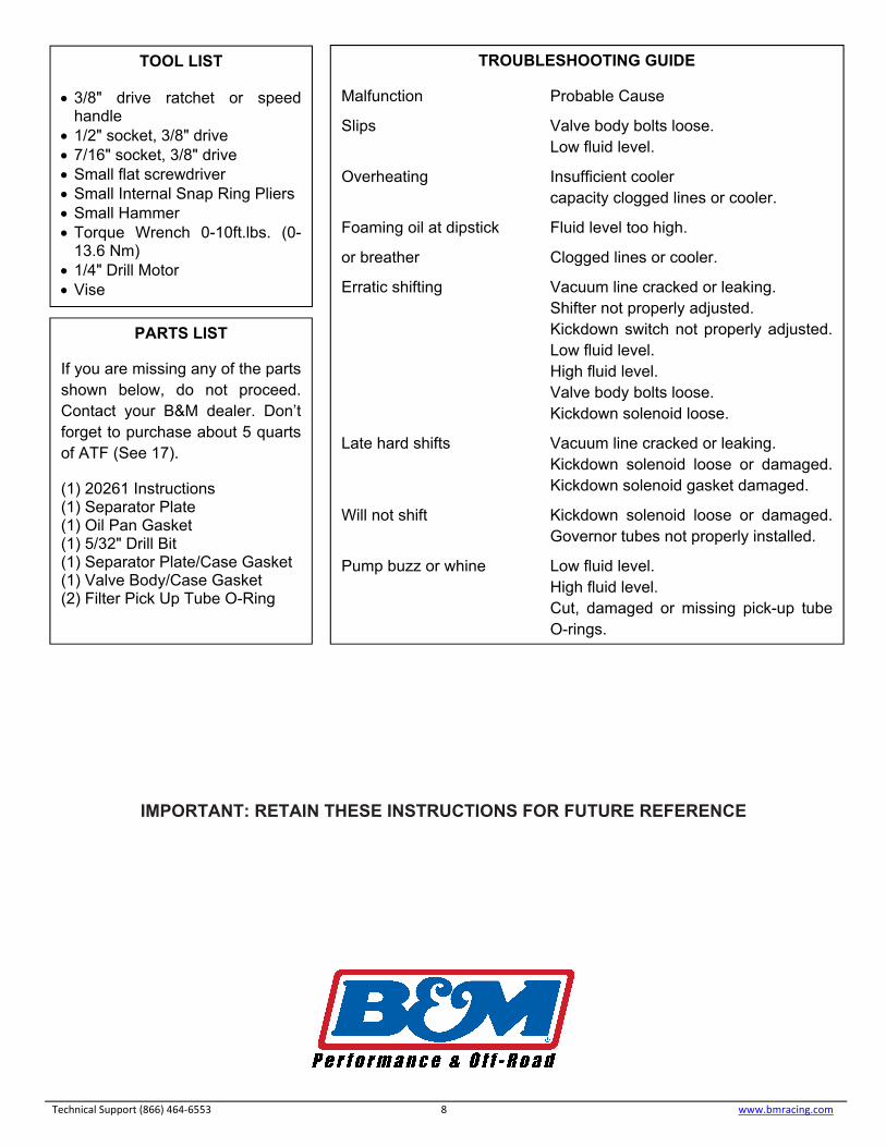
9. Check Ball Placement: Install check balls inthe locations shown in Fig. 10 as follows: HeavyDuty: Seven check balls, one each, in locations1-7. Street: Six check balls, one each, inlocations 1, 2, 3, 5, 6, 7 (do not install check ball#4).
Note: Transmissions used in vehicles over 10,000 GVW do not have a factory installed check ball in position #7. If your vehicle is of this type (over 10,000 GVW) do not install a check ball in position #7 for Heavy Duty or Street levels. Fig. 10
11. Carefully examine Detent Solenoid. Makesure the rubber seal is in good condition andhas no nicks or cuts (See Fig. 11). If the sealis damaged, you will have to replace thesolenoid. If the seal leaks the transmission willbe in passing gear all the time. Install thesolenoid with two (2) 1/4-20 bolts. Tightenbolts FINGER TIGHT for now. Remove thepan bolt you used to hold the plate and gasketin place. Fig. 11
16. Clean oil pan and scrape off any old gasket material from pan and case. You may want to install aB&M Drain Plug kit before installing the pan. The drain plug kit will help eliminate the mess whenchanging transmission oil. Install pan and new gasket and torque bolts 8-10ft.lbs. (11-13.6 Nm).
17. Add 4 quarts of fresh ATF. Dexron II is fine for Heavy Duty Level applications, however werecommend B&M Trick Shift for Street Level for firm positive shifts and improved transmission life.With the vehicles wheels still off the ground, start the engine and shift transmission through all gears.Place selector in neutral and check the fluid level. It should be between the Add and Full marks. Donot overfill!! This can cause foaming and overheating. Turn off engine and lower vehicle.
18. Drive vehicle several miles to warm up the transmission. Park on level surface and check ATFlevel. It should be between Add and Full.
Technical Support (866) 464‐6553 7 www.bmracing.com
15. Install two (2) filter O-rings on filter pick-up tube (See Fig. 12). Lubricate O-rings withclean ATF then push pick-up tube and filterassembly up into transmission, install spacer(if present) and shoulder bolt then torque to8-10ft.lbs.. (11-13.6 Nm).
Fig. 12
IMPORTANT: RETAIN THESE INSTRUCTIONS FOR FUTURE REFERENCE
Technical Support (866) 464‐6553 8 www.bmracing.com
TOOL LIST
3/8" drive ratchet or speedhandle
1/2" socket, 3/8" drive 7/16" socket, 3/8" drive Small flat screwdriver Small Internal Snap Ring Pliers Small Hammer Torque Wrench 0-10ft.lbs. (0-
13.6 Nm) 1/4" Drill Motor Vise
PARTS LIST
If you are missing any of the parts shown below, do not proceed. Contact your B&M dealer. Don’t forget to purchase about 5 quarts of ATF (See 17).
(1) 20261 Instructions(1) Separator Plate(1) Oil Pan Gasket(1) 5/32" Drill Bit(1) Separator Plate/Case Gasket(1) Valve Body/Case Gasket(2) Filter Pick Up Tube O-Ring
TROUBLESHOOTING GUIDE
Malfunction Probable Cause
Slips Valve body bolts loose. Low fluid level.
Overheating Insufficient cooler capacity clogged lines or cooler.
Foaming oil at dipstick Fluid level too high.
or breather Clogged lines or cooler.
Erratic shifting Vacuum line cracked or leaking. Shifter not properly adjusted. Kickdown switch not properly adjusted.Low fluid level. High fluid level. Valve body bolts loose. Kickdown solenoid loose.
Late hard shifts Vacuum line cracked or leaking. Kickdown solenoid loose or damaged. Kickdown solenoid gasket damaged.
Will not shift Kickdown solenoid loose or damaged. Governor tubes not properly installed.
Pump buzz or whine Low fluid level. High fluid level. Cut, damaged or missing pick-up tube O-rings.