installation instructions - lennox · tent operation down to 55°f (13°c) dry bulb for cases where...
TRANSCRIPT
Page 1
07/10
��������506508−01
����������
� 2010 Lennox Industries Inc.
Dallas, Texas, USA
THIS MANUAL MUST BE LEFT WITH THEHOMEOWNER FOR FUTURE REFERENCE
INSTALLATIONINSTRUCTIONS
G51MP SERIES UNITSGAS UNITS506508−0107/2010
Supersedes 505,065M
Table of Contents
Unit Dimensions 2. . . . . . . . . . . . . . . . . . . . . . . . . . . . . . . G51MP Parts Identification 3. . . . . . . . . . . . . . . . . . . . . . Shipping and Packing List 4. . . . . . . . . . . . . . . . . . . . . . . Safety Information 4. . . . . . . . . . . . . . . . . . . . . . . . . . . . . . Use of Furnace as a Construction Heater 5. . . . . . . . . . General 6. . . . . . . . . . . . . . . . . . . . . . . . . . . . . . . . . . . . . . . Combustion, Dilution & Ventilation Air 6. . . . . . . . . . . . . Installation − Setting Equipment 9. . . . . . . . . . . . . . . . . . Filters 16. . . . . . . . . . . . . . . . . . . . . . . . . . . . . . . . . . . . . . . . Duct System 16. . . . . . . . . . . . . . . . . . . . . . . . . . . . . . . . . . Pipe & Fittings Specifications 16. . . . . . . . . . . . . . . . . . . Vent Piping Guidelines 18. . . . . . . . . . . . . . . . . . . . . . . . . Joint Cementing Procedure 19. . . . . . . . . . . . . . . . . . . . . Venting Practices 19. . . . . . . . . . . . . . . . . . . . . . . . . . . . . . Gas Piping 33. . . . . . . . . . . . . . . . . . . . . . . . . . . . . . . . . . . Electrical 36. . . . . . . . . . . . . . . . . . . . . . . . . . . . . . . . . . . . . Unit Start−Up 40. . . . . . . . . . . . . . . . . . . . . . . . . . . . . . . . . . Gas Pressure Adjustment 41. . . . . . . . . . . . . . . . . . . . . . High Altitude Information 43. . . . . . . . . . . . . . . . . . . . . . . Other Unit Adjustments 45. . . . . . . . . . . . . . . . . . . . . . . . Service 48. . . . . . . . . . . . . . . . . . . . . . . . . . . . . . . . . . . . . . Planned Service 50. . . . . . . . . . . . . . . . . . . . . . . . . . . . . . Repair Parts List 50. . . . . . . . . . . . . . . . . . . . . . . . . . . . . . Troubleshooting 51. . . . . . . . . . . . . . . . . . . . . . . . . . . . . . . Ignition Control Board Diagnostic Codes 54. . . . . . . . . Vent Pipe Sizing Worksheet 55. . . . . . . . . . . . . . . . . . . . Start−Up & Performance Check List 55. . . . . . . . . . . . . .
WHAT TO DO IF YOU SMELL GAS:Do not store or use gasoline or otherflammable vapors and liquids in thevicinity of this or any other ap-pliance.
Installation and service must beperformed by a qualified installer,service agency or the gas supplier.
� Do not try to light any appliance.
� Do not touch any electrical switch; do notuse any phone in your building.
� Immediately call your gas supplier from aneighbor’s phone. Follow the gas supplier’sinstructions.
� If you cannot reach your gas supplier, callthe fire department.
FIRE OR EXPLOSION HAZARD.
Failure to follow safety warnings exact-ly could result in serious injury, death,or property damage.
WARNING
� Leave the building immediately.
Litho U.S.A.

Page 2
G51MP Unit Dimensions − inches (mm)
*Bottom ReturnAir Opening
*Bottom ReturnAir Opening
ELECTRICAL INLET(Either Side)
SUPPLY AIROPENING
AIR FLOW
FRONT VIEW SIDE VIEW
TOP VIEW
A
B 9/16 (14)
C 3/4 (19)
3/4 (19)
28−1/2(724)
19−7/16(494)
23−1/2(597)
4−1/4(108)
11−5/8 (295)
Right
9−3/4 (248)
Left
4−7/8 (124) Right
2−1/4 (57) Left40(1016)
4(102)
1−15/16 (49)
23(584)
14**(356)
9/16(14)
16(406)
14−3/4(375)
5/8 (16)
23-3/4 (603)
25 (635)
GAS PIPING INLET(Either Side)
EXHAUST AIR OUTLET(Either Side)
CONDENSATETRAP CONNECTION
(Either Side)
2−1/2(64)
18-3/4 (476)
1OPTIONALEXTERNAL
SIDE RETURNAIR FILTER KIT
(Either Side)
1 OPTIONALEXTERNAL
SIDE RETURNAIR FILTER KIT
(Either Side)
*OPTIONALRETURN CUTOUT
(Either Side)
1 Optional External Side Return Air Filter Kit is not for usewith the optional RAB Return Air Base.
*NOTE − 60C and 60D size units installed in upflow applica-tions that require air volumes over 1800 cfm (850 L/s) musthave one of the following:1. Single side return air with transition, to accommodate
20 x 25 x 1 in. (508 x 635 x 25 mm) air filter.Required to maintain proper air velocity.
2. Single side return air with optional RAB Return Air Base3. Bottom return air.4. Return air from both sides.5. Bottom and one side return air.Refer to Engineering Handbook for additional information.
**Consider sizing requirements for optional IAQ equipmentbefore cutting side return opening.
COMBUSTION AIR INTAKE(Either Side)6−1/2
(165)
4−1/8(103)
6−1/2(165)
6−3/4(171)
5−1/2(140)
3−1/8(79)
Model No.A B C
in. mm in. mm in. mm
G51MP−24B−045G51MP−36B−045G51MP−36B−070
17−1/2 446 16−3/8 416 16 406
G51MP−36C−090G51MP−48C−090G51MP−60C−090G51MP−48C−110G51MP−60C−110
21 533 19−7/8 504 19−1/2 495
G51MP−60D−135 24−1/2 622 23−3/8 546 23 584
Page 3
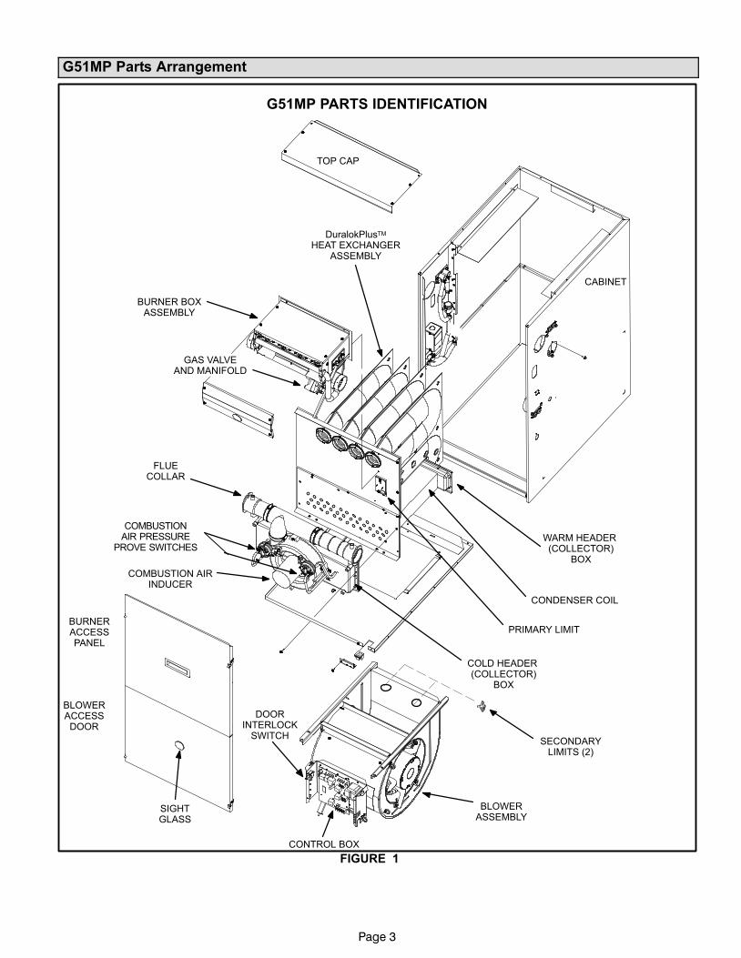
G51MP Parts Arrangement
G51MP PARTS IDENTIFICATION
FIGURE 1
TOP CAP
CABINET
BURNER BOXASSEMBLY
SIGHTGLASS
DuralokPlusTM
HEAT EXCHANGERASSEMBLY
CONDENSER COIL
CONTROL BOX
DOORINTERLOCK
SWITCH
COLD HEADER (COLLECTOR)
BOX
COMBUSTION AIRINDUCER
BLOWERACCESSDOOR
BURNERACCESSPANEL
FLUECOLLAR
COMBUSTIONAIR PRESSURE
PROVE SWITCHES
PRIMARY LIMIT
WARM HEADER (COLLECTOR)
BOX
GAS VALVEAND MANIFOLD
SECONDARYLIMITS (2)
BLOWERASSEMBLY
Page 4
G51MP Gas Furnace
The G51MP Category IV gas furnace is shipped ready for
installation in the upflow, downflow, horizontal left air dis-
charge or horizontal right air discharge position. The fur-
nace is shipped with the bottom panel in place. The bot-
tom panel must be removed if the unit is to be installed in
upflow applications with bottom return air. The bottom
panel must also be removed and discarded in all downflow
or horizontal applications.
The furnace is equipped for installation in natural gas ap-
plications. A conversion kit (ordered separately) is re-
quired for use in propane/LP gas applications.
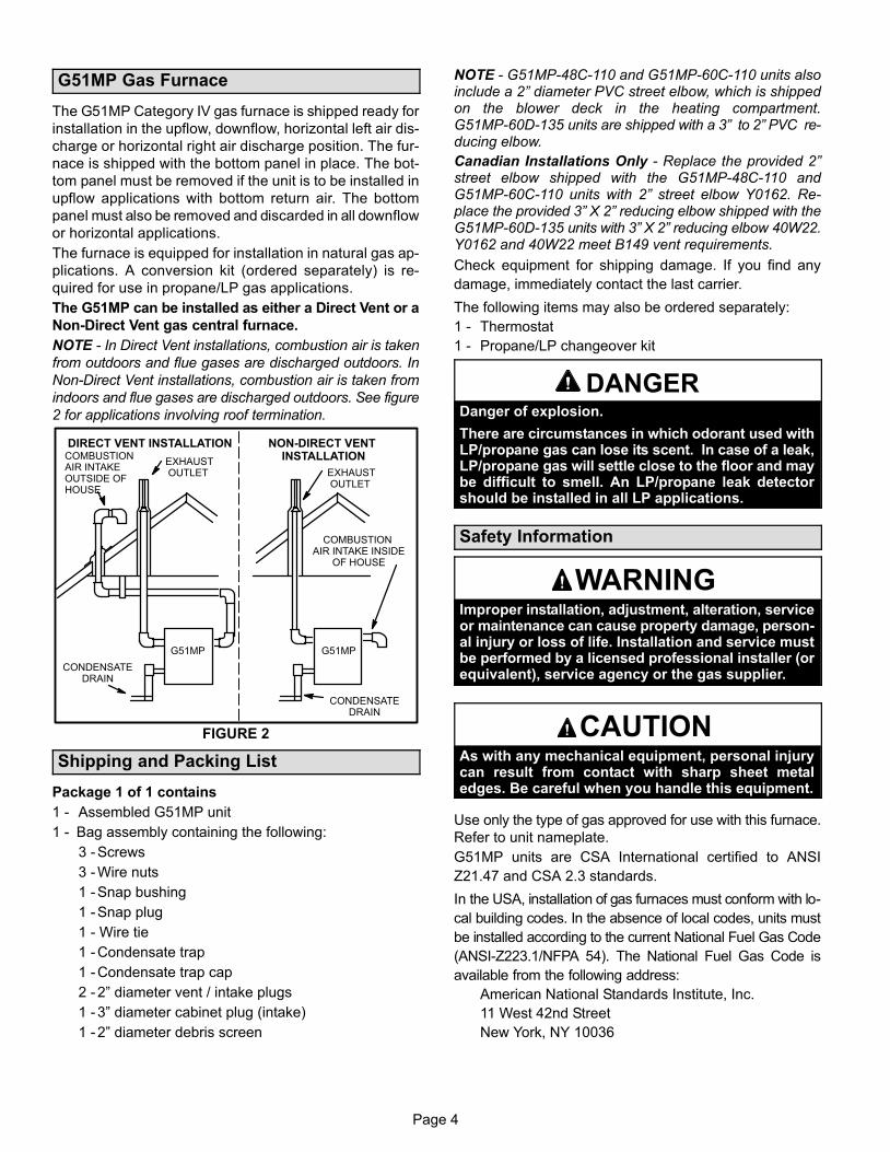
The G51MP can be installed as either a Direct Vent or a
Non−Direct Vent gas central furnace.
NOTE − In Direct Vent installations, combustion air is taken
from outdoors and flue gases are discharged outdoors. In
Non−Direct Vent installations, combustion air is taken from
indoors and flue gases are discharged outdoors. See figure
2 for applications involving roof termination.
FIGURE 2
DIRECT VENT INSTALLATION NON−DIRECT VENT INSTALLATION
EXHAUST OUTLET
COMBUSTIONAIR INTAKEOUTSIDE OFHOUSE
CONDENSATEDRAIN
EXHAUST OUTLET
G51MP
COMBUSTION AIR INTAKE INSIDE
OF HOUSE
G51MP
CONDENSATEDRAIN
Shipping and Packing List
Package 1 of 1 contains
1 − Assembled G51MP unit
1 − Bag assembly containing the following:
3 − Screws
3 − Wire nuts
1 − Snap bushing
1 − Snap plug
1 − Wire tie
1 − Condensate trap
1 − Condensate trap cap
2 − 2" diameter vent / intake plugs
1 − 3" diameter cabinet plug (intake)
1 − 2" diameter debris screen
NOTE − G51MP−48C−110 and G51MP−60C−110 units alsoinclude a 2" diameter PVC street elbow, which is shippedon the blower deck in the heating compartment.G51MP−60D−135 units are shipped with a 3" to 2" PVC re-ducing elbow.
Canadian Installations Only − Replace the provided 2"street elbow shipped with the G51MP−48C−110 andG51MP−60C−110 units with 2" street elbow Y0162. Re-place the provided 3" X 2" reducing elbow shipped with theG51MP−60D−135 units with 3" X 2" reducing elbow 40W22.Y0162 and 40W22 meet B149 vent requirements.
Check equipment for shipping damage. If you find any
damage, immediately contact the last carrier.
The following items may also be ordered separately:
1 − Thermostat
1 − Propane/LP changeover kit
DANGERDanger of explosion.
There are circumstances in which odorant used withLP/propane gas can lose its scent. In case of a leak,LP/propane gas will settle close to the floor and maybe difficult to smell. An LP/propane leak detectorshould be installed in all LP applications.
Safety Information
WARNINGImproper installation, adjustment, alteration, serviceor maintenance can cause property damage, person-al injury or loss of life. Installation and service mustbe performed by a licensed professional installer (orequivalent), service agency or the gas supplier.
CAUTIONAs with any mechanical equipment, personal injurycan result from contact with sharp sheet metaledges. Be careful when you handle this equipment.
Use only the type of gas approved for use with this furnace.
Refer to unit nameplate.
G51MP units are CSA International certified to ANSI
Z21.47 and CSA 2.3 standards.
In the USA, installation of gas furnaces must conform with lo-
cal building codes. In the absence of local codes, units must
be installed according to the current National Fuel Gas Code
(ANSI-Z223.1/NFPA 54). The National Fuel Gas Code is
available from the following address:
American National Standards Institute, Inc.
11 West 42nd Street
New York, NY 10036

Page 5
In Canada, installation must conform with current National
Standard of Canada CSA-B149 Natural Gas and Propane
Installation Codes, local plumbing or waste water codes
and other applicable local codes.
In order to ensure proper unit operation in non−direct vent
applications, combustion and ventilation air supply must be
provided according to the current National Fuel Gas Code
or CSA-B149 standard.
This furnace is CSA International certified for installation
clearances to combustible material as listed on the unit
nameplate and in the tables in figures 8, 13 and 17. Accessi-
bility and service clearances must take precedence over fire
protection clearances.
NOTE − For installation on combustible floors, the furnace
shall not be installed directly on carpeting, tile, or other
combustible material other than wood flooring.
For installation in a residential garage, the furnace must
be installed so that the burner(s) and the ignition source
are located no less than 18 inches (457 mm) above the
floor. The furnace must be located or protected to avoid
physical damage by vehicles. When a furnace is installed
in a public garage, hangar, or other building that has a haz-
ardous atmosphere, the furnace must be installed accord-
ing to recommended good practice requirements and cur-
rent National Fuel Gas Code or CSA B149 standards.
NOTE − Furnace must be adjusted to obtain a temperature
rise within the range specified on the unit nameplate. Failure
to do so may cause erratic limit operation and premature heat
exchanger failure.
This G51MP furnace may be used as a high−static unit
heater. The G51MP may also be installed in an aircraft han-
gar in accordance with the Standard for Aircraft Hangars
(ANSI/NFPA No. 408−1990).
Installation in parking structures must be in accordance
with the Standard for Parking Structures (ANSI/NFPA No.
88A−1991). Installation in repair garages must be in accor-
dance with the Standard for Repair Garages (ANSI/NFPA
No. 88B−1991).
This G51MP furnace must be installed so that its electrical
components are protected from water.
When this furnace is used with cooling units, it shall be
installed in parallel with, or on the upstream side of, cooling
units to avoid condensation in the heating compartment.
With a parallel flow arrangement, a damper (or other means
to control the flow of air) must adequately prevent chilled air
from entering the furnace. If the damper is manually oper-
ated, it must be equipped to prevent operation of either the
heating or the cooling unit, unless it is in the full HEAT or
COOL setting.
When installed, this furnace must be electrically grounded
according to local codes. In addition, in the United States,
installation must conform with the current National Electric
Code, ANSI/NFPA No. 70. The National Electric Code
(ANSI/NFPA No. 70) is available from the following ad-
dress:
National Fire Protection Association
1 Battery March Park
Quincy, MA 02269
In Canada, all electrical wiring and grounding for the unit
must be installed according to the current regulations of the
Canadian Electrical Code Part I (CSA Standard C22.1)
and/or local codes.
NOTE − This furnace is designed for a minimum continu-
ous return air temperature of 60°F (16°C) or an intermit-
tent operation down to 55°F (13°C) dry bulb for cases
where a night setback thermostat is used. Return air tem-
perature must not exceed 85°F (29°C) dry bulb.
The G51MP furnace may be installed in alcoves, closets,
attics, basements, garages, and utility rooms.
This furnace design has not been CSA certified for installa-
tion in mobile homes, recreational vehicles, or outdoors.
Never use an open flame to test for gas leaks. Check all
connections using a commercially available soap solution
made specifically for leak detection.
Use of Furnace as Construction Heater
Lennox does not recommend the use of G51MP units as a
construction heater during any phase of construction. Very
low return air temperatures, harmful vapors and operation
of the unit with clogged or misplaced filters will damage the
unit.
G51MP units may be used for heating of buildings or struc-
tures under construction, if the following conditions are
met:
� The vent system must be permanently installed per
these installation instructions.
� A room thermostat must control the furnace. The use of
fixed jumpers that will provide continuous heating is not
allowed.
� The return air duct must be provided and sealed to the
furnace.
� Return air temperature range between 60°F (16°C) and
80°F (27°C) must be maintained.
� Air filters must be installed in the system and must be
maintained during construction.
� Air filters must be replaced upon construction comple-
tion.
� The input rate and temperature rise must be set per the
furnace rating plate.
Page 6
� One hundred percent (100%) outdoor air must be pro-
vided for combustion air requirements during construc-
tion. Temporary ducting may supply outdoor air to the
furnace. Do not connect duct directly to the furnace.
Size the temporary duct following these instructions in
section for Combustion, Dilution and Ventilation Air in a
confined space with air from outside.
� The furnace heat exchanger, components, duct system,
air filters and evaporator coils must be thoroughly
cleaned following final construction clean−up.
� All furnace operating conditions (including ignition, in-
put rate, temperature rise and venting) must be verified
according to these installation instructions.
General
These instructions are intended as a general guide and do
not supersede local codes in any way. Consult authorities
having jurisdiction before installation.
In addition to the requirements outlined previously, the fol-
lowing general recommendations must be considered
when installing a G51MP furnace:
• Place the furnace as close to the center of the air dis-
tribution system as possible. The furnace should also be
located close to the chimney or vent termination point.
• When the furnace is installed in non−direct vent applica-
tions, do not install the furnace where drafts might blow
directly into it. This could cause improper combustion
and unsafe operation.
• When the furnace is installed in non−direct vent applica-
tions, do not block the furnace combustion air opening
with clothing, boxes, doors, etc. Air is needed for proper
combustion and safe unit operation.
• When the furnace is installed in an attic or other insu-
lated space, keep insulation away from the furnace.
• When the furnace is installed in an unconditioned
space, consider provisions required to prevent freezing
of condensate drain system.
WARNINGProduct contains fiberglass wool.
Disturbing the insulation in this product duringinstallation, maintenance, or repair will expose youto fiberglass wool. Breathing this may cause lungcancer. (Fiberglass wool is known to the State of Cal-ifornia to cause cancer.)
Fiberglass wool may also cause respiratory, skin,and eye irritation.
To reduce exposure to this substance or for furtherinformation, consult material safety data sheetsavailable from address shown below, or contact yoursupervisor.
Lennox Industries Inc.P.O. Box 799900Dallas, TX 75379−9900
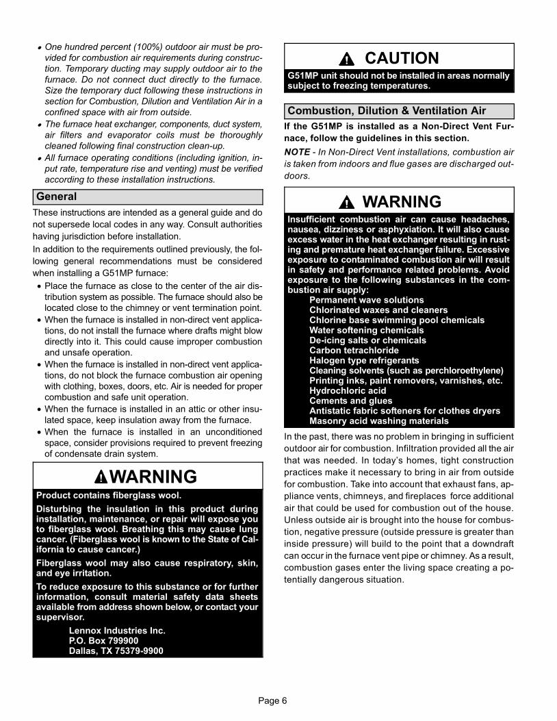
CAUTIONG51MP unit should not be installed in areas normallysubject to freezing temperatures.
Combustion, Dilution & Ventilation Air
If the G51MP is installed as a Non−Direct Vent Fur-
nace, follow the guidelines in this section.
NOTE − In Non−Direct Vent installations, combustion air
is taken from indoors and flue gases are discharged out−
doors.
WARNINGInsufficient combustion air can cause headaches,nausea, dizziness or asphyxiation. It will also causeexcess water in the heat exchanger resulting in rust-ing and premature heat exchanger failure. Excessiveexposure to contaminated combustion air will resultin safety and performance related problems. Avoidexposure to the following substances in the com-bustion air supply:
Permanent wave solutionsChlorinated waxes and cleanersChlorine base swimming pool chemicalsWater softening chemicalsDe−icing salts or chemicalsCarbon tetrachlorideHalogen type refrigerantsCleaning solvents (such as perchloroethylene)Printing inks, paint removers, varnishes, etc.Hydrochloric acidCements and gluesAntistatic fabric softeners for clothes dryersMasonry acid washing materials
In the past, there was no problem in bringing in sufficient
outdoor air for combustion. Infiltration provided all the air
that was needed. In today’s homes, tight construction
practices make it necessary to bring in air from outside
for combustion. Take into account that exhaust fans, ap-
pliance vents, chimneys, and fireplaces force additional
air that could be used for combustion out of the house.
Unless outside air is brought into the house for combus-
tion, negative pressure (outside pressure is greater than
inside pressure) will build to the point that a downdraft
can occur in the furnace vent pipe or chimney. As a result,
combustion gases enter the living space creating a po-
tentially dangerous situation.
Page 7
In the absence of local codes concerning air for combus−
tion and ventilation, use the guidelines and procedures in
this section to install G51MP furnaces to ensure efficient
and safe operation. You must consider combustion air
needs and requirements for exhaust vents and gas pip-
ing. A portion of this information has been reprinted with
permission from the National Fuel Gas Code (ANSI−
Z223.1/NFPA 54). This reprinted material is not the com-
plete and official position of the ANSI on the referenced
subject, which is represented only by the standard in its
entirety.
In Canada, refer to the CSA B149 installation codes.
CAUTIONDo not install the furnace in a corrosive or contami-nated atmosphere. Meet all combustion and ventila-tion air requirements, as well as all local codes.
All gas-fired appliances require air for the combustion pro-
cess. If sufficient combustion air is not available, the fur-
nace or other appliance will operate inefficiently and un-
safely. Enough air must be provided to meet the needs of all
fuel−burning appliances and appliances such as exhaust
fans which force air out of the house. When fireplaces, ex-
haust fans, or clothes dryers are used at the same time as
the furnace, much more air is required to ensure proper
combustion and to prevent a downdraft. Insufficient air
causes incomplete combustion which can result in carbon
monoxide.
In addition to providing combustion air, fresh outdoor air di-
lutes contaminants in the indoor air. These contaminants
may include bleaches, adhesives, detergents, solvents
and other contaminants which can corrode furnace compo-
nents.
The requirements for providing air for combustion and ven-
tilation depend largely on whether the furnace is installed in
an unconfined or a confined space.
Unconfined Space
An unconfined space is an area such as a basement or
large equipment room with a volume greater than 50 cubic
feet (1.42 m3) per 1,000 Btu (.29 kW) per hour of the com-
bined input rating of all appliances installed in that space.
This space also includes adjacent rooms which are not
separated by a door. Though an area may appear to be un-
confined, it might be necessary to bring in outdoor air for
combustion if the structure does not provide enough air by
infiltration. If the furnace is located in a building of tight
construction with weather stripping and caulking around
the windows and doors, follow the procedures in the air
from outside section.
Confined Space
A confined space is an area with a volume less than 50 cubic
feet (1.42 m3) per 1,000 Btu (.29 kW) per hour of the com−
bined input rating of all appliances installed in that space. This
definition includes furnace closets or small equipment rooms.
When the furnace is installed so that supply ducts carry air
circulated by the furnace to areas outside the space con-
taining the furnace, the return air must be handled by ducts
which are sealed to the furnace casing and which terminate
outside the space containing the furnace. This is especially
important when the furnace is mounted on a platform in a
confined space such as a closet or small equipment room.
Even a small leak around the base of the unit at the platform
or at the return air duct connection can cause a potentially
dangerous negative pressure condition. Air for combustion
and ventilation can be brought into the confined space ei-
ther from inside the building or from outside.
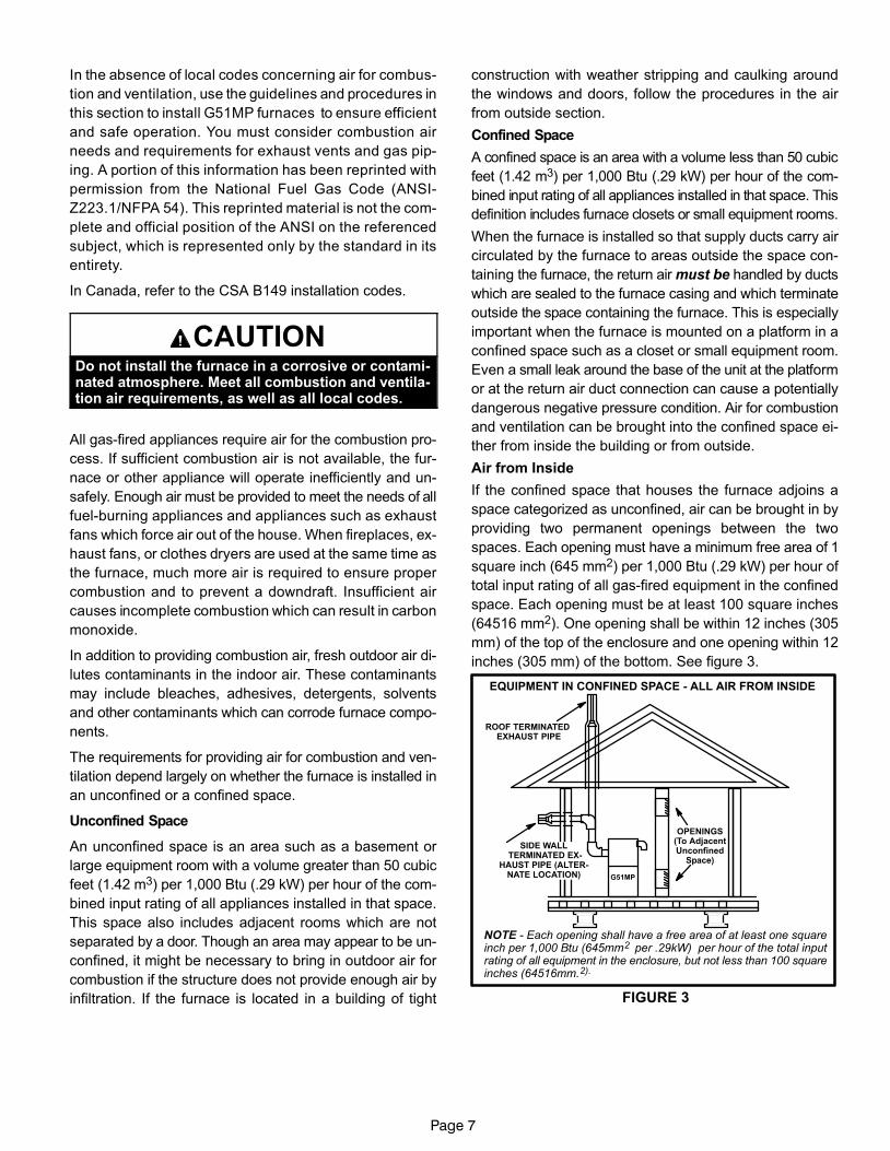
Air from Inside
If the confined space that houses the furnace adjoins a
space categorized as unconfined, air can be brought in by
providing two permanent openings between the two
spaces. Each opening must have a minimum free area of 1
square inch (645 mm2) per 1,000 Btu (.29 kW) per hour of
total input rating of all gas−fired equipment in the confined
space. Each opening must be at least 100 square inches
(64516 mm2). One opening shall be within 12 inches (305
mm) of the top of the enclosure and one opening within 12
inches (305 mm) of the bottom. See figure 3.
FIGURE 3
EQUIPMENT IN CONFINED SPACE − ALL AIR FROM INSIDE
OPENINGS(To AdjacentUnconfined
Space)
NOTE − Each opening shall have a free area of at least one squareinch per 1,000 Btu (645mm2 per .29kW) per hour of the total inputrating of all equipment in the enclosure, but not less than 100 squareinches (64516mm.2).
G51MP
ROOF TERMINATED EXHAUST PIPE
SIDE WALL TERMINATED EX-
HAUST PIPE (ALTER-NATE LOCATION)
Page 8
Air from Outside
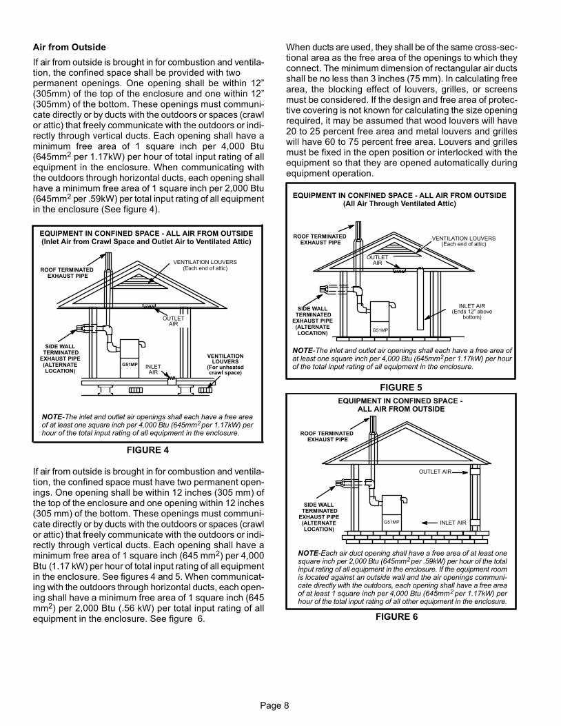
If air from outside is brought in for combustion and ventila-tion, the confined space shall be provided with twopermanent openings. One opening shall be within 12"(305mm) of the top of the enclosure and one within 12"(305mm) of the bottom. These openings must communi-cate directly or by ducts with the outdoors or spaces (crawlor attic) that freely communicate with the outdoors or indi-rectly through vertical ducts. Each opening shall have aminimum free area of 1 square inch per 4,000 Btu(645mm2 per 1.17kW) per hour of total input rating of allequipment in the enclosure. When communicating withthe outdoors through horizontal ducts, each opening shallhave a minimum free area of 1 square inch per 2,000 Btu(645mm2 per .59kW) per total input rating of all equipmentin the enclosure (See figure 4).
FIGURE 4
EQUIPMENT IN CONFINED SPACE − ALL AIR FROM OUTSIDE(Inlet Air from Crawl Space and Outlet Air to Ventilated Attic)
NOTE−The inlet and outlet air openings shall each have a free areaof at least one square inch per 4,000 Btu (645mm2 per 1.17kW) perhour of the total input rating of all equipment in the enclosure.
OUTLETAIR
INLETAIR
VENTILATIONLOUVERS
(For unheatedcrawl space)
G51MP
ROOF TERMINATED EXHAUST PIPE
VENTILATION LOUVERS(Each end of attic)
SIDE WALL TERMINATED
EXHAUST PIPE(ALTERNATELOCATION)
If air from outside is brought in for combustion and ventila-tion, the confined space must have two permanent open-ings. One opening shall be within 12 inches (305 mm) ofthe top of the enclosure and one opening within 12 inches(305 mm) of the bottom. These openings must communi-cate directly or by ducts with the outdoors or spaces (crawlor attic) that freely communicate with the outdoors or indi-rectly through vertical ducts. Each opening shall have aminimum free area of 1 square inch (645 mm2) per 4,000Btu (1.17 kW) per hour of total input rating of all equipmentin the enclosure. See figures 4 and 5. When communicat-ing with the outdoors through horizontal ducts, each open-ing shall have a minimum free area of 1 square inch (645mm2) per 2,000 Btu (.56 kW) per total input rating of allequipment in the enclosure. See figure 6.
When ducts are used, they shall be of the same cross−sec-tional area as the free area of the openings to which theyconnect. The minimum dimension of rectangular air ductsshall be no less than 3 inches (75 mm). In calculating freearea, the blocking effect of louvers, grilles, or screensmust be considered. If the design and free area of protec-tive covering is not known for calculating the size openingrequired, it may be assumed that wood louvers will have20 to 25 percent free area and metal louvers and grilleswill have 60 to 75 percent free area. Louvers and grillesmust be fixed in the open position or interlocked with theequipment so that they are opened automatically duringequipment operation.
FIGURE 5
EQUIPMENT IN CONFINED SPACE − ALL AIR FROM OUTSIDE(All Air Through Ventilated Attic)
NOTE−The inlet and outlet air openings shall each have a free area ofat least one square inch per 4,000 Btu (645mm2 per 1.17kW) per hourof the total input rating of all equipment in the enclosure.
OUTLETAIR
VENTILATION LOUVERS(Each end of attic)
INLET AIR(Ends 12" above
bottom)
G51MP
ROOF TERMINATED EXHAUST PIPE
SIDE WALL TERMINATED
EXHAUST PIPE(ALTERNATELOCATION)
FIGURE 6
G51MP
EQUIPMENT IN CONFINED SPACE − ALL AIR FROM OUTSIDE
OUTLET AIR
INLET AIR
NOTE−Each air duct opening shall have a free area of at least onesquare inch per 2,000 Btu (645mm2 per .59kW) per hour of the totalinput rating of all equipment in the enclosure. If the equipment roomis located against an outside wall and the air openings communi-cate directly with the outdoors, each opening shall have a free areaof at least 1 square inch per 4,000 Btu (645mm2 per 1.17kW) perhour of the total input rating of all other equipment in the enclosure.
ROOF TERMINATED EXHAUST PIPE
SIDE WALL TERMINATED
EXHAUST PIPE(ALTERNATELOCATION)

Page 9
Installation − Setting Equipment
WARNINGDo not install the furnace on its front or its back. Donot connect the return air ducts to the back of the fur-nace. Doing so will adversely affect the operation ofthe safety control devices, which could result in per-sonal injury or death.
Select a location that allows for the required clearances
that are listed on the unit nameplate. Also consider gas
supply connections, electrical supply, vent connection,
condensate trap and drain connections, and installation
and service clearances [24 inches (610 mm) at unit
front]. The unit must be level from front to back and side
to side. The unit may be tilted slightly (maximum 1/2 in.)
from back to front to aid in the draining of the heat ex-
changer. See figure 7.
NOTE − 1/3 hp blower motors are equipped with four flex-
ible mounting legs, and 1/2 hp blower motors are equipped
with three flexible legs and one rigid leg. The rigid leg is
equipped with a shipping bolt and a flat white plastic wash-
er (rather than the rubber mounting grommet used with a
flexible mounting leg). The bolt and washer must be re-
moved before the furnace is placed into operation. Af-
ter the bolt and washer have been removed, the rigid leg
will not touch the blower housing.
NOTE − The G51MP−60D−135 units are equipped with a
shipping pad under the blower housing. Remove the ship-
ping pad prior to operation.
Allow for clearances to combustible materials as indicated
on the unit nameplate. Minimum clearances for closet or al-
cove installations are shown in figures 8, 13 and 17.
FIGURE 7
SETTING EQUIPMENT
UPFLOW APPLICATION DOWNFLOW APPLICATION
HORIZONTAL APPLICATION
FRONT VIEW
SIDE VIEW
FRONT VIEW
END VIEW
FRONT VIEW
SIDE VIEW
AIR FLOW
AIR FLOW
AIR FLOW
UNITFRONT
AIR FLOW
AIR FLOW
UNITFRONT
UNITFRONT
1/2"max.
1/2"max.
1/2"max.
UNIT MUST BE LEVEL SIDE−TO−SIDE IN ALL APPLICATIONS.
UNIT SHOULD BE LEVEL FROM LEFT TO RIGHT BUT MAY BETILTED SLIGHTLY (MAX. 1/2") FROM BACK TO FRONTTO AID IN THE DRAINING OF THE HEAT EXCHANGER.
Page 10
WARNINGBlower access panel must be securely in place whenblower and burners are operating. Gas fumes, whichcould contain carbon monoxide, can be drawn intoliving space resulting in personal injury or death.
WARNINGImproper installation of the furnace can result in per-sonal injury or death. Combustion and flue productsmust never be allowed to enter the return air systemor air in the living space. Use sheet metal screws andjoint tape to seal return air system to furnace.In platform installations with furnace return, the fur-nace should be sealed airtight to the return air ple-num. A door must never be used as a portion of thereturn air duct system. The base must provide astable support and an airtight seal to the furnace. Al-low absolutely no sagging, cracks, gaps, etc.For no reason should return and supply air duct sys-tems ever be connected to or from other heating de-vices such as a fireplace or stove, etc. Fire, explo-sion, carbon monoxide poisoning, personal injuryand/or property damage could result.
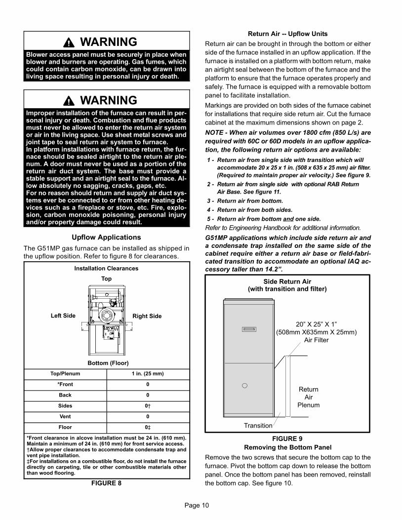
Upflow Applications
The G51MP gas furnace can be installed as shipped in
the upflow position. Refer to figure 8 for clearances.
Installation Clearances
Top
Bottom (Floor)
Left Side Right Side
Top/Plenum 1 in. (25 mm)
*Front 0
Back 0
Sides 0†
Vent 0
Floor 0‡
*Front clearance in alcove installation must be 24 in. (610 mm).Maintain a minimum of 24 in. (610 mm) for front service access.†Allow proper clearances to accommodate condensate trap andvent pipe installation.‡For installations on a combustible floor, do not install the furnacedirectly on carpeting, tile or other combustible materials otherthan wood flooring.
FIGURE 8
Return Air −− Upflow Units
Return air can be brought in through the bottom or either
side of the furnace installed in an upflow application. If the
furnace is installed on a platform with bottom return, make
an airtight seal between the bottom of the furnace and the
platform to ensure that the furnace operates properly and
safely. The furnace is equipped with a removable bottom
panel to facilitate installation.
Markings are provided on both sides of the furnace cabinet
for installations that require side return air. Cut the furnace
cabinet at the maximum dimensions shown on page 2.
NOTE − When air volumes over 1800 cfm (850 L/s) are
required with 60C or 60D models in an upflow applica-
tion, the following return air options are available:
1 − Return air from single side with transition which will
accommodate 20 x 25 x 1 in. (508 x 635 x 25 mm) air filter.
(Required to maintain proper air velocity.) See figure 9.
2 − Return air from single side with optional RAB Return
Air Base. See figure 11.
3 − Return air from bottom.
4 − Return air from both sides.
5 − Return air from bottom and one side.
Refer to Engineering Handbook for additional information.
G51MP applications which include side return air and
a condensate trap installed on the same side of the
cabinet require either a return air base or field−fabri-
cated transition to accommodate an optional IAQ ac-
cessory taller than 14.2".
Side Return Air(with transition and filter)
FIGURE 9
Return
Air
Plenum
Transition
20" X 25" X 1"
(508mm X635mm X 25mm)
Air Filter
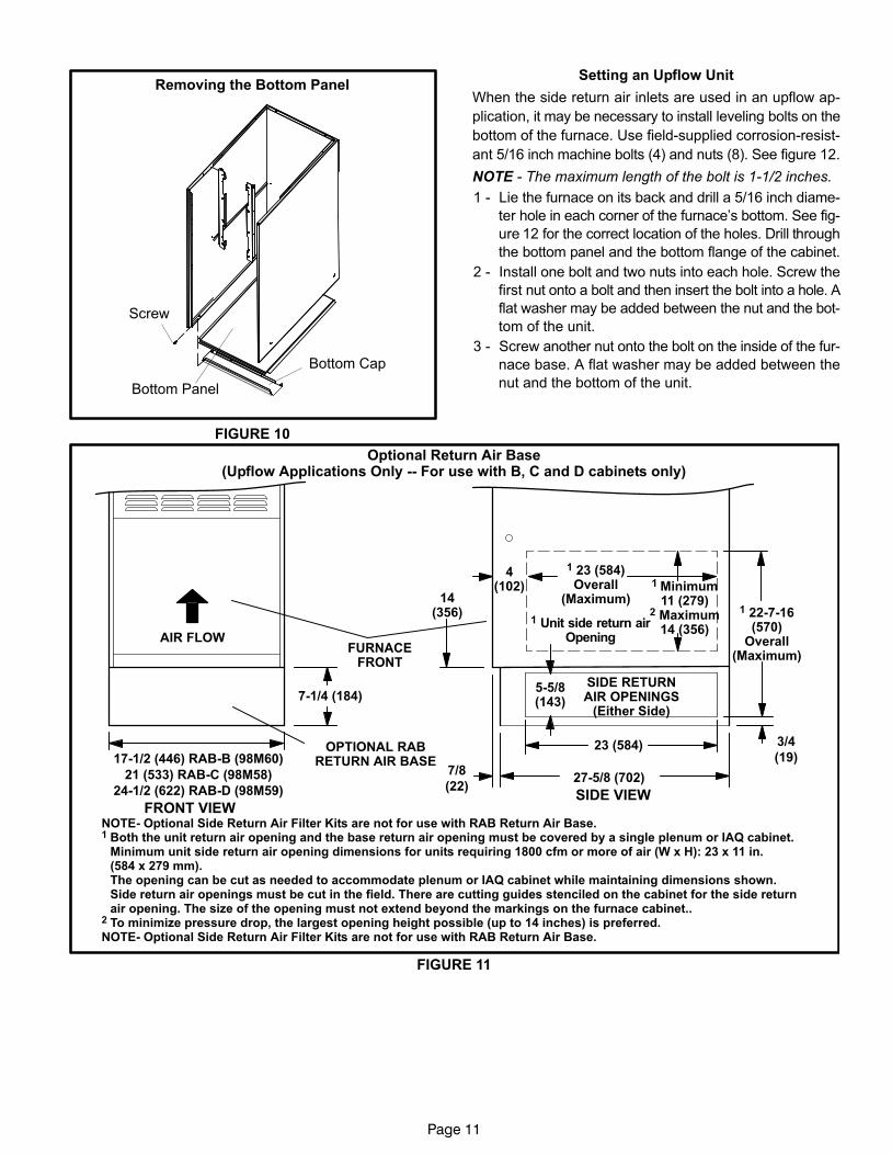
Removing the Bottom Panel
Remove the two screws that secure the bottom cap to the
furnace. Pivot the bottom cap down to release the bottom
panel. Once the bottom panel has been removed, reinstall
the bottom cap. See figure 10.
Page 11
Removing the Bottom Panel
FIGURE 10
Screw
Bottom Panel
Bottom Cap
Setting an Upflow Unit
When the side return air inlets are used in an upflow ap-
plication, it may be necessary to install leveling bolts on the
bottom of the furnace. Use field−supplied corrosion−resist-
ant 5/16 inch machine bolts (4) and nuts (8). See figure 12.
NOTE − The maximum length of the bolt is 1−1/2 inches.
1 − Lie the furnace on its back and drill a 5/16 inch diame-
ter hole in each corner of the furnace’s bottom. See fig-
ure 12 for the correct location of the holes. Drill through
the bottom panel and the bottom flange of the cabinet.
2 − Install one bolt and two nuts into each hole. Screw the
first nut onto a bolt and then insert the bolt into a hole. A
flat washer may be added between the nut and the bot-
tom of the unit.
3 − Screw another nut onto the bolt on the inside of the fur-
nace base. A flat washer may be added between the
nut and the bottom of the unit.
FIGURE 11
NOTE− Optional Side Return Air Filter Kits are not for use with RAB Return Air Base.1 Both the unit return air opening and the base return air opening must be covered by a single plenum or IAQ cabinet.
Minimum unit side return air opening dimensions for units requiring 1800 cfm or more of air (W x H): 23 x 11 in. (584 x 279 mm).The opening can be cut as needed to accommodate plenum or IAQ cabinet while maintaining dimensions shown.Side return air openings must be cut in the field. There are cutting guides stenciled on the cabinet for the side return air opening. The size of the opening must not extend beyond the markings on the furnace cabinet..
2 To minimize pressure drop, the largest opening height possible (up to 14 inches) is preferred.NOTE− Optional Side Return Air Filter Kits are not for use with RAB Return Air Base.
1 Unit side return airOpening
FRONT VIEWSIDE VIEW
27−5/8 (702)
4(102)
1 23 (584)Overall
(Maximum)
OPTIONAL RABRETURN AIR BASE
23 (584)
7−1/4 (184)
7/8
(22)
3/4
(19)
1 22−7−16(570)
Overall(Maximum)
SIDE RETURNAIR OPENINGS
(Either Side)
FURNACEFRONT
14(356)
AIR FLOW
5−5/8(143)
1 Minimum11 (279)
2 Maximum14 (356)
21 (533) RAB−C (98M58)
24−1/2 (622) RAB−D (98M59)
17−1/2 (446) RAB−B (98M60)
Optional Return Air Base(Upflow Applications Only −− For use with B, C and D cabinets only)

Page 12
4 − Adjust the outside nut to the appropriate height and
tighten the inside nut to secure the arrangement.
NOTE − The unit may be tilted back−to−front a maximum of
1/2". This will ensure proper draining of the heat exchang-
er.
FIGURE 12
1−3/4(44)
1−3/4(44)
3/8(10)
1−3/4 (44)
3/8(10)
3/8(10)
3/8(10)
1−3/4(44)
Leveling Bolt Installation
Leveling BoltLocations
Leveling BoltLocations
Inches (mm)
Furnace Front
FurnaceBottom
Downflow Applications
The unit may be installed three ways in downflow applica-
tions: on non−combustible flooring, on combustible flooring
using an additive base, or on a reverse−flow cooling cabi-
net. Do not drag the unit across the floor in the down-
flow position. Flange damage will result.
Refer to figure 13 for clearances in downflow applica-
tions.
Downflow Application Installation Clearances
Top
Bottom
Left Side Right Side
Top 0
*Front 0
Back 0
Sides 0†
Vent 0
Floor NC‡
*Front clearance in alcove installation must be 24 in. (610 mm).Maintain a minimum of 24 in. (610 mm) for front service access.†Allow proper clearances to accommodate condensate trap andvent pipe installation.‡The furnace may be installed on a combustible wood floor if an op-tional additive base is installed between the furnace and the com-bustible floor.
FIGURE 13
Installation on Non−Combustible Flooring
1 − Cut floor opening keeping in mind clearances listed on
unit rating plate. Also keep in mind gas supply connec-
tions, electrical supply, flue and air intake connections
and sufficient installation and servicing clearances.
See table 1 for correct floor opening size.
2 − Flange warm air plenum and lower the plenum into the
opening.
3 − Set the unit over the plenum and seal the plenum to
the unit.
3 − Ensure that the seal is adequate.
TABLE 1NON−COMBUSTIBLE FLOOR OPENING SIZE
Cabinet WidthFront to Rear Side to Side
in. mm in. mm
B Cabinet (17.5") 19 − 3/4 502 16 − 5/8 422
C Cabinet (21") 19 − 3/4 502 20−1/8 511
D Cabinet (24.5") 19 − 3/4 502 23 − 5/8 600

Page 13
Installation on Combustible Flooring
(Using an Additive Base)
1 − When unit is installed on a combustible floor, an addi-
tive base must be installed between the furnace and
the floor. The base must be ordered separately. See
table 2 for opening size to cut in floor.
CAUTIONThe furnace and additive base shall not be installeddirectly on carpeting, tile, or other combustible ma-terial other than wood flooring.
TABLE 2ADDITIVE BASE FLOOR OPENING SIZE
CabinetWidth
CatalogNumber
Front to Rear Side to Side
in. mm in. mm
B Cabinet(17.5")
11M60 22 559 18 − 3/4 476
C Cabinet(21")
11M61 22 559 22 − 3/4 578
D Cabinet(24.5")
11M62 22 559 25 − 3/4 654
2 − After opening is cut, set additive base into opening.
3 − Check fiberglass strips on additive base to make sure
they are properly glued and positioned.
4 − Lower supply air plenum into additive base until ple-
num flanges seal against fiberglass strips.
NOTE − Be careful not to damage fiberglass strips.
Check for a tight seal.
5 − Set the furnace over the plenum.
6 − Ensure that the seal between the furnace and plenum
is adequate.
G51MP UNIT
SUPPLY AIR PLENUM
ADDITIVE BASE
PROPERLYSIZED FLOOR
OPENING
FIGURE 14
Installation on Cooling Cabinet
1 − Refer to reverse−flow coil installation instructions for
correctly sized opening in floor and installation of cabi-
net.
2 − When cooling cabinet is in place, set and secure the
furnace according to the instructions that are provided
with the cooling coil. Secure the furnace to the cabinet.
3 − Seal the cabinet and check for air leaks.
Return Air Opening −− Downflow Units
The following steps should be taken when installing ple-
num:
1 − Bottom edge of plenum should be flanged with a
hemmed edge (See figure 15 or 16).
2 − Sealing strips should be used to ensure an airtight seal
between the cabinet and the plenum.
3 − In all cases, plenum should be secured to top of fur-
nace using sheet metal screws.
4 − Make certain that an adequate seal is made.
ÉÉÉÉ
FIGURE 15
SECURE FROM
OUTSIDE CABINET
PLENUM
(Field Provided)
SEALING STRIP
(Field Provided)Side View
CABINET
SIDE PANEL
ÉÉÉÉSECURE FROM
INSIDE CABINET
PLENUM
(Field Provided)SEALING STRIP
(Field Provided)
Side View
CABINET
SIDE PANEL
FIGURE 16
Page 14
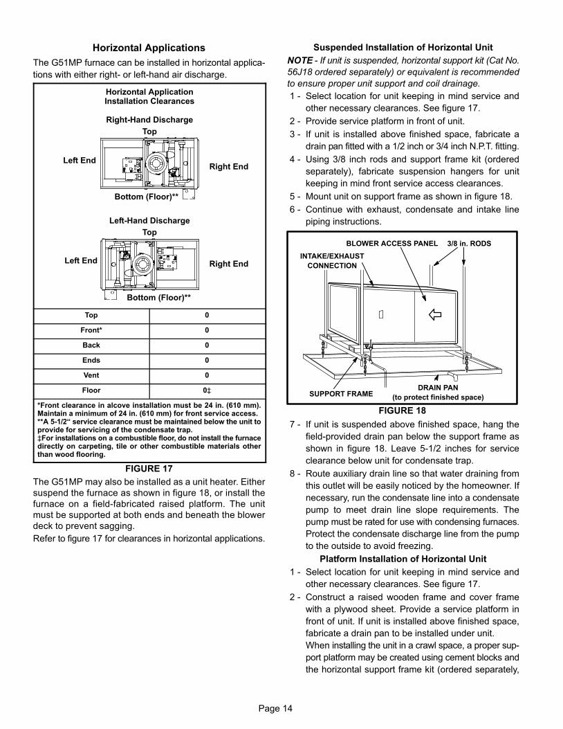
Horizontal Applications
The G51MP furnace can be installed in horizontal applica-
tions with either right− or left−hand air discharge.
Horizontal ApplicationInstallation Clearances
Top
Left EndRight End
Right−Hand Discharge
Left−Hand Discharge
Top
Left End Right End
Bottom (Floor)**
Bottom (Floor)**
Top 0
Front* 0
Back 0
Ends 0
Vent 0
Floor 0‡
*Front clearance in alcove installation must be 24 in. (610 mm).Maintain a minimum of 24 in. (610 mm) for front service access.**A 5−1/2� service clearance must be maintained below the unit toprovide for servicing of the condensate trap.‡For installations on a combustible floor, do not install the furnacedirectly on carpeting, tile or other combustible materials otherthan wood flooring.
FIGURE 17
The G51MP may also be installed as a unit heater. Either
suspend the furnace as shown in figure 18, or install the
furnace on a field−fabricated raised platform. The unit
must be supported at both ends and beneath the blower
deck to prevent sagging.
Refer to figure 17 for clearances in horizontal applications.
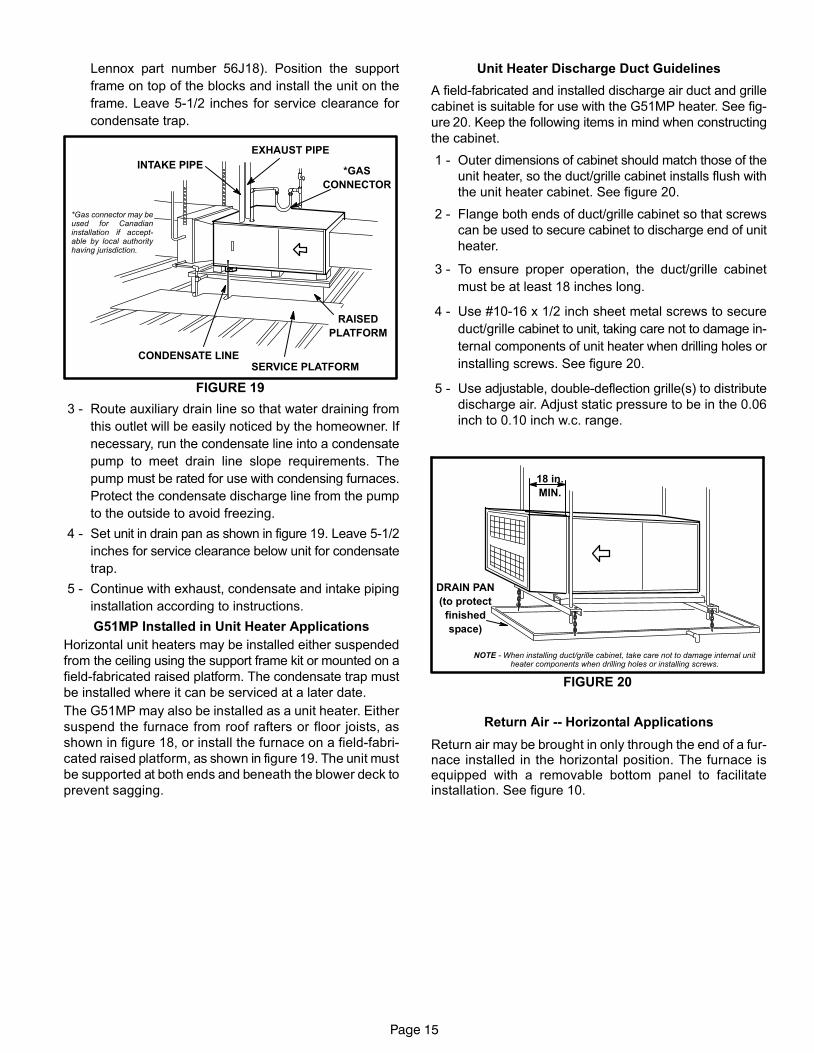
Suspended Installation of Horizontal Unit
NOTE − If unit is suspended, horizontal support kit (Cat No.
56J18 ordered separately) or equivalent is recommended
to ensure proper unit support and coil drainage.
1 − Select location for unit keeping in mind service and
other necessary clearances. See figure 17.
2 − Provide service platform in front of unit.
3 − If unit is installed above finished space, fabricate a
drain pan fitted with a 1/2 inch or 3/4 inch N.P.T. fitting.
4 − Using 3/8 inch rods and support frame kit (ordered
separately), fabricate suspension hangers for unit
keeping in mind front service access clearances.
5 − Mount unit on support frame as shown in figure 18.
6 − Continue with exhaust, condensate and intake line
piping instructions.
FIGURE 18
BLOWER ACCESS PANEL 3/8 in. RODS
SUPPORT FRAME
INTAKE/EXHAUST
CONNECTION
DRAIN PAN
(to protect finished space)
7 − If unit is suspended above finished space, hang the
field−provided drain pan below the support frame as
shown in figure 18. Leave 5−1/2 inches for service
clearance below unit for condensate trap.
8 − Route auxiliary drain line so that water draining from
this outlet will be easily noticed by the homeowner. If
necessary, run the condensate line into a condensate
pump to meet drain line slope requirements. The
pump must be rated for use with condensing furnaces.
Protect the condensate discharge line from the pump
to the outside to avoid freezing.
Platform Installation of Horizontal Unit
1 − Select location for unit keeping in mind service and
other necessary clearances. See figure 17.
2 − Construct a raised wooden frame and cover frame
with a plywood sheet. Provide a service platform in
front of unit. If unit is installed above finished space,
fabricate a drain pan to be installed under unit.
When installing the unit in a crawl space, a proper sup-
port platform may be created using cement blocks and
the horizontal support frame kit (ordered separately,
Page 15
Lennox part number 56J18). Position the support
frame on top of the blocks and install the unit on the
frame. Leave 5−1/2 inches for service clearance for
condensate trap.
INTAKE PIPE*GAS
CONNECTOR
SERVICE PLATFORM
RAISED
PLATFORM
CONDENSATE LINE
*Gas connector may beused for Canadianinstallation if accept-able by local authorityhaving jurisdiction.
EXHAUST PIPE
FIGURE 19
3 − Route auxiliary drain line so that water draining from
this outlet will be easily noticed by the homeowner. If
necessary, run the condensate line into a condensate
pump to meet drain line slope requirements. The
pump must be rated for use with condensing furnaces.
Protect the condensate discharge line from the pump
to the outside to avoid freezing.
4 − Set unit in drain pan as shown in figure 19. Leave 5−1/2
inches for service clearance below unit for condensate
trap.
5 − Continue with exhaust, condensate and intake piping
installation according to instructions.
G51MP Installed in Unit Heater Applications
Horizontal unit heaters may be installed either suspended
from the ceiling using the support frame kit or mounted on a
field−fabricated raised platform. The condensate trap must
be installed where it can be serviced at a later date.
The G51MP may also be installed as a unit heater. Either
suspend the furnace from roof rafters or floor joists, as
shown in figure 18, or install the furnace on a field−fabri-
cated raised platform, as shown in figure 19. The unit must
be supported at both ends and beneath the blower deck to
prevent sagging.
Unit Heater Discharge Duct Guidelines
A field−fabricated and installed discharge air duct and grille
cabinet is suitable for use with the G51MP heater. See fig-
ure 20. Keep the following items in mind when constructing
the cabinet.
1 − Outer dimensions of cabinet should match those of the
unit heater, so the duct/grille cabinet installs flush with
the unit heater cabinet. See figure 20.
2 − Flange both ends of duct/grille cabinet so that screws
can be used to secure cabinet to discharge end of unit
heater.
3 − To ensure proper operation, the duct/grille cabinet
must be at least 18 inches long.
4 − Use #10−16 x 1/2 inch sheet metal screws to secure
duct/grille cabinet to unit, taking care not to damage in-
ternal components of unit heater when drilling holes or
installing screws. See figure 20.
5 − Use adjustable, double−deflection grille(s) to distribute
discharge air. Adjust static pressure to be in the 0.06
inch to 0.10 inch w.c. range.
FIGURE 20
18 in.
MIN.
NOTE − When installing duct/grille cabinet, take care not to damage internal unitheater components when drilling holes or installing screws.
DRAIN PAN
(to protect
finished
space)
Return Air −− Horizontal Applications
Return air may be brought in only through the end of a fur-nace installed in the horizontal position. The furnace isequipped with a removable bottom panel to facilitateinstallation. See figure 10.

Page 16
Filters
This unit is not equipped with a filter or rack. A field−pro-
vided filter is required for the unit to operate properly. Table
3 lists recommended filter sizes.
A filter must be in place whenever the unit is operating.
TABLE 3
FurnaceCabinet Width
Filter Size
Side Return Bottom Return
17−1/2" 16 X 25 X 1 (1) 16 X 25 X 1 (1)
21" 16 X 25 X 1 (1) 20 X 25 X 1 (1)
24−1/2" 16 X 25 X 1 (2) 24 X 25 X 1 (1)
Duct System
Use industry-approved standards to size and install the
supply and return air duct system. This will result in a quiet
and low-static system that has uniform air distribution.
NOTE − Operation of this furnace in heating mode (indoor
blower operating at selected heating speed) with an exter-
nal static pressure which exceeds 0.5 inches w.c. may re-
sult in erratic limit operation.
Supply Air Plenum
If the furnace is installed without a cooling coil, a removable
access panel should be installed in the supply air duct. The
access panel should be large enough to permit inspection
(by reflected light) of the heat exchanger for leaks after the
furnace is installed. The furnace access panel must always
be in place when the furnace is operating and it must not
allow leaks into the supply air duct system.
Return Air Plenum
NOTE − Return air must not be drawn from a room
where this furnace, or any other gas−fueled ap-
pliance (i.e., water heater), or carbon monoxide−
producing device (i.e., wood fireplace) is installed.
When return air is drawn from a room, a negative pres-
sure is created in the room. If a gas appliance is operating
in a room with negative pressure, the flue products can
be pulled back down the vent pipe and into the room. This
reverse flow of the flue gas may result in incomplete com-
bustion and the formation of carbon monoxide gas. This
toxic gas might then be distributed throughout the house
by the furnace duct system.
Return air can be brought in through the bottom or either
side of the furnace. If a furnace with bottom return air is
installed on a platform, make an airtight seal between the
bottom of the furnace and the platform to ensure that the
unit operates properly and safely. Use fiberglass sealing
strips, caulking, or equivalent sealing method between the
plenum and the furnace cabinet to ensure a tight seal. If a
filter is installed, size the return air duct to fit the filter frame.
Pipe & Fittings Specifications
All pipe, fittings, primer and solvent cement must conform
with American National Standard Institute and the Ameri-
can Society for Testing and Materials (ANSI/ASTM) stan-
dards. The solvent shall be free flowing and contain no
lumps, undissolved particles or any foreign matter that ad-
versely affects the joint strength or chemical resistance of
the cement. The cement shall show no gelation, stratifica-
tion, or separation that cannot be removed by stirring. Re-
fer to the table 4 below for approved piping and fitting mate-
rials.
TABLE 4PIPING AND FITTINGS SPECIFICATIONS
PIPE & FITTING MATERIALASTM
SPECIFICATION
Schedule 40 PVC (Pipe) D1785
Schedule 40 PVC (Cellular Core Pipe) F891
Schedule 40 PVC (Fittings) D2466
Schedule 40 CPVC (Pipe) F441
Schedule 40 CPVC (Fittings) F438
SDR−21 PVC or SDR−26 PVC (Pipe) D2241
SDR−21 CPVC or SDR−26 CPVC (Pipe) F442
Schedule 40 ABS Cellular Core DWV (Pipe) F628
Schedule 40 ABS (Pipe) D1527
Schedule 40 ABS (Fittings) D2468
ABS−DWV (Drain Waste & Vent)(Pipe & Fittings)
D2661
PVC−DWV (Drain Waste & Vent) Pipe & Fittings)
D2665
PRIMER & SOLVENT CEMENTASTM
SPECIFICATION
PVC & CPVC Primer F656
PVC Solvent Cement D2564
CPVC Solvent Cement F493
ABS Solvent Cement D2235
PVC/CPVC/ABS All Purpose Cement For Fit-tings & Pipe of the same material D2564, D2235,
F493ABS to PVC or CPVC Transition SolventCement D3138
CANADA PIPE & FITTING & SOLVENTCEMENT
MARKING
PVC & CPVC Pipe and Fittings
ULCS636PVC & CPVC Solvent Cement
ABS to PVC or CPVC Transition Cement
CAUTIONSolvent cements for plastic pipe are flammable liq-uids and should be kept away from all sources ofignition. Do not use excessive amounts of solventcement when making joints. Good ventilation shouldbe maintained to reduce fire hazard and to minimizebreathing of solvent vapors. Avoid contact of cementwith skin and eyes.

Page 17
Use PVC primer and solvent cement or ABS solvent cement
meeting ASTM specifications, refer to Table 4. As an alter-
nate, use all purpose cement, to bond ABS, PVC, or CPVC
pipe when using fittings and pipe made of the same materi-
als. Use transition solvent cement when bonding ABS to ei-
ther PVC or CPVC.
Low temperature solvent cement is recommended. Metal or
plastic strapping may be used for vent pipe hangers. Uni-
formly apply a liberal coat of PVC primer for PVC or use a
clean dry cloth for ABS to clean inside socket surface of fit-
ting and male end of pipe to depth of fitting socket.
Canadian Applications Only − Pipe, fittings, primer
and solvent cement used to vent (exhaust) this ap-
pliance must be certified to ULC S636 and supplied by a
single manufacturer as part of an approved vent (ex-
haust) system. When bonding the vent system to the fur-
nace, use ULC S636 approved One−Step Transition Ce-
ment to bond the pipe to the flue collar, or to bond the 90°
elbow or reducing 90° elbow to the flue collar. In addi-
tion, the first three feet of vent pipe from the furnace flue
collar must be accessible for inspection.
Table 5 lists the available exhaust termination kits, as well
as vent pipe equivalencies which must be used when siz-
ing vent pipe. All Lennox vent terminations are PVC.
TABLE 5OUTDOOR TERMINATION KITS AND CORRESPONDING EQUIVALENCIES
UNITMODEL
VENTPIPEDIA.(in.)
Vent Pipe Length Equivalency (feet)
Outdoor Exhaust
Accelerator(Dia. XLength)
Outdoor Exhaust
Accelerator(Dia. XLength)
1−1/2"Concentric
Kit
2"Concentric
Kit
3"Concentric
Kit
2" Wall PlateKit
3" Wall PlateKit
2" WallRing Kit
1−1/2" X 12" 2" X 12"71M80
or�44W92��
69M29or
�44W92��
60L46or 44W93�
22G44or 30G28�
44J40or 81J20�
15F74
24B−04536B−045
2 4 NotAllowed
12 NotAllowed
NotAllowed
4 4* 4
2−1/2 5 NotAllowed
15 NotAllowed
NotAllowed
5 5* 5
3 7 NotAllowed
21 NotAllowed
NotAllowed
7 7* 7
4 14 NotAllowed
42 NotAllowed
NotAllowed
14 14* 14
36B−070
2 4 NotAllowed
12 NotAllowed
NotAllowed
4 4* 4
2−1/2 5 NotAllowed
15 NotAllowed
NotAllowed
5 5* 5
3 8 NotAllowed
24 NotAllowed
NotAllowed
8 8* 8
4 14 NotAllowed
42 NotAllowed
NotAllowed
14 14* 14
36C−09048C−09060C−090
2 NotAllowed
1 NotAllowed
3 3 NotAllowed
1 1**
2−1/2 NotAllowed
2 NotAllowed
6 6 NotAllowed
2 2**
3 NotAllowed
2 NotAllowed
6 6 NotAllowed
2 2**
4 NotAllowed
4 NotAllowed
12 12 NotAllowed
4 4**
48C−11060C−110
2 NotAllowed
1 NotAllowed
3 3 NotAllowed
1 1**
2−1/2 NotAllowed
2 NotAllowed
6 6 NotAllowed
2 2***
3 NotAllowed
2 NotAllowed
6 6 NotAllowed
2 2***
4 NotAllowed
4 NotAllowed
12 12 NotAllowed
4 4***
60D−135
3 NotAllowed
6 NotAllowed
NotAllowed
15 NotAllowed
6 6***
4 NotAllowed
10 NotAllowed
NotAllowed
25 NotAllowed
10 10***
*Requires field−provided and installed 1−1/2" exhaust accelerator.
**Requires field−provided and installed 2" exhaust accelerator.
***For use only in non−direct vent applications, when snow riser is not re-quired. Requires field−provided and installed 2" exhaust accelerator.
� Termination kits 44W92, 44W93, 30G28 & 81J20 are ULC−636 ap-proved for Canadian Installation.
�� The 44W92 Concentric kit is provided with a 1−1/2" accelerator whichmust be installed on the exhaust outlet when this kit is used with theG51MP−24B−045, G51MP−36B−045 and G51MP−36B−070 furnaces.
Page 18
Vent Piping Guidelines
The G51MP can be installed as either a Non−Direct Ventor a Direct Vent gas central furnace.
NOTE − In Non-Direct Vent installations, combustion air istaken from indoors and flue gases are discharged outdoors.In Direct Vent installations, combustion air is taken from out-doors and flue gases are discharged outdoors.
Intake and exhaust pipe sizing in Direct Vent applicationsand exhaust pipe sizing in Non-Direct Vent applications −−Size pipe according to tables 7 and 8. Table 7 lists the mini-mum equivalent vent pipe lengths permitted. Table 8 liststhe maximum equivalent pipe lengths permitted.
Maximum vent length is defined as:Total length (linear feet) of pipe,Plus Equivalent length (feet) of fittings,Plus Equivalent length (feet) of termination.NOTE − Include ALL pipe and ALL fittings, both in doors and outdoors.
Regardless of the diameter of pipe used, the standard roofand wall terminations described in section Exhaust PipingTerminations should be used. Exhaust vent terminationpipe is sized to optimize the velocity of the exhaust gas asit exits the termination. Refer to table 9.
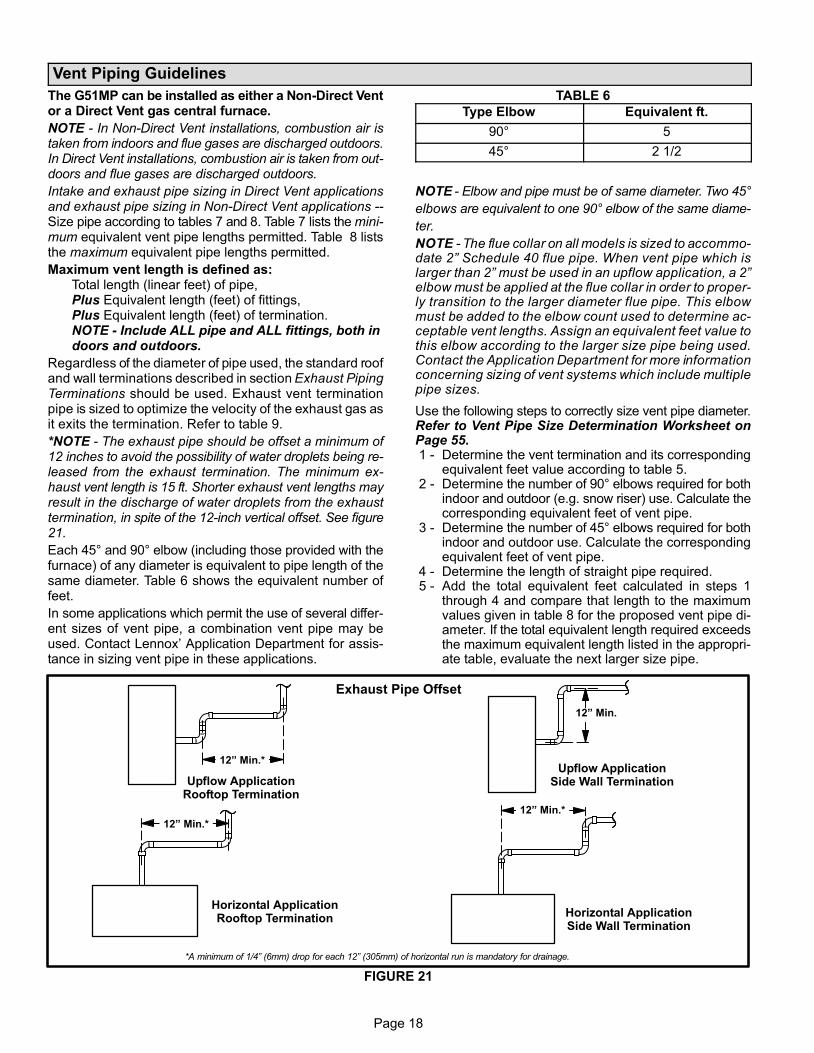
*NOTE − The exhaust pipe should be offset a minimum of12 inches to avoid the possibility of water droplets being re-leased from the exhaust termination. The minimum ex-haust vent length is 15 ft. Shorter exhaust vent lengths mayresult in the discharge of water droplets from the exhausttermination, in spite of the 12−inch vertical offset. See figure21.
Each 45° and 90° elbow (including those provided with thefurnace) of any diameter is equivalent to pipe length of thesame diameter. Table 6 shows the equivalent number offeet.
In some applications which permit the use of several differ-ent sizes of vent pipe, a combination vent pipe may beused. Contact Lennox’ Application Department for assis-tance in sizing vent pipe in these applications.
TABLE 6
Type Elbow Equivalent ft.
90° 5
45° 2 1/2
NOTE − Elbow and pipe must be of same diameter. Two 45°
elbows are equivalent to one 90° elbow of the same diame-
ter.
NOTE − The flue collar on all models is sized to accommo-date 2" Schedule 40 flue pipe. When vent pipe which islarger than 2" must be used in an upflow application, a 2"elbow must be applied at the flue collar in order to proper-ly transition to the larger diameter flue pipe. This elbowmust be added to the elbow count used to determine ac-ceptable vent lengths. Assign an equivalent feet value tothis elbow according to the larger size pipe being used.Contact the Application Department for more informationconcerning sizing of vent systems which include multiplepipe sizes.
Use the following steps to correctly size vent pipe diameter.Refer to Vent Pipe Size Determination Worksheet onPage 55. 1 − Determine the vent termination and its corresponding
equivalent feet value according to table 5. 2 − Determine the number of 90° elbows required for both
indoor and outdoor (e.g. snow riser) use. Calculate thecorresponding equivalent feet of vent pipe.
3 − Determine the number of 45° elbows required for bothindoor and outdoor use. Calculate the correspondingequivalent feet of vent pipe.
4 − Determine the length of straight pipe required. 5 − Add the total equivalent feet calculated in steps 1
through 4 and compare that length to the maximumvalues given in table 8 for the proposed vent pipe di-ameter. If the total equivalent length required exceedsthe maximum equivalent length listed in the appropri-ate table, evaluate the next larger size pipe.
FIGURE 21
Exhaust Pipe Offset
12" Min.*
12" Min.*
12" Min.*
12" Min.
Upflow ApplicationRooftop Termination
Upflow ApplicationSide Wall Termination
Horizontal ApplicationRooftop Termination
Horizontal ApplicationSide Wall Termination
*A minimum of 1/4" (6mm) drop for each 12" (305mm) of horizontal run is mandatory for drainage.
Page 19
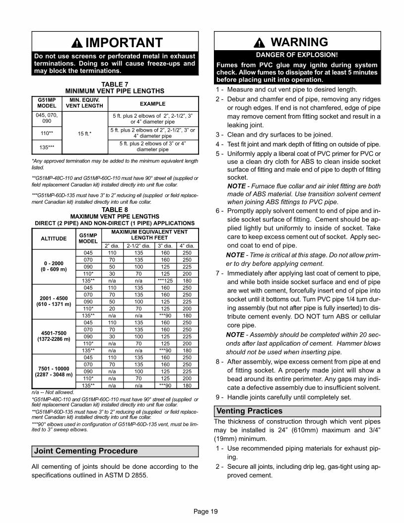
IMPORTANTDo not use screens or perforated metal in exhaustterminations. Doing so will cause freeze−ups andmay block the terminations.
TABLE 7MINIMUM VENT PIPE LENGTHS
G51MPMODEL
MIN. EQUIV.VENT LENGTH EXAMPLE
045, 070,090
15 ft.*
5 ft. plus 2 elbows of 2", 2−1/2", 3"or 4" diameter pipe
110**5 ft. plus 2 elbows of 2", 2−1/2", 3" or
4" diameter pipe
135***5 ft. plus 2 elbows of 3" or 4"
diameter pipe
*Any approved termination may be added to the minimum equivalent length
listed.
**G51MP−48C−110 and G51MP−60C−110 must have 90° street ell (supplied or
field replacement Canadian kit) installed directly into unit flue collar.
***G51MP−60D−135 must have 3" to 2" reducing ell (supplied or field replace-
ment Canadian kit) installed directly into unit flue collar.
TABLE 8MAXIMUM VENT PIPE LENGTHS
DIRECT (2 PIPE) AND NON−DIRECT (1 PIPE) APPLICATIONS
ALTITUDEG51MPMODEL
MAXIMUM EQUIVALENT VENTLENGTH FEET
2" dia. 2−1/2" dia. 3" dia. 4" dia.
0 − 2000(0 − 609 m)
045 110 135 160 250
070 70 135 160 250
090 50 100 125 225
110* 30 70 125 200
135** n/a n/a ***125 180
2001 − 4500(610 − 1371 m)
045 110 135 160 250
070 70 135 160 250
090 50 100 125 225
110* 20 70 125 200
135** n/a n/a ***90 180
4501−7500(1372−2286 m)
045 110 135 160 250
070 70 135 160 250
090 30 100 125 225
110* n/a 70 125 200
135** n/a n/a ***90 180
7501 − 10000(2287 − 3048 m)
045 110 135 160 250
070 70 135 160 250
090 n/a 100 125 225
110* n/a 70 125 200
135** n/a n/a ***90 180
n/a −− Not allowed.
*G51MP−48C−110 and G51MP−60C−110 must have 90° street ell (supplied orfield replacement Canadian kit) installed directly into unit flue collar.
**G51MP−60D−135 must have 3" to 2" reducing ell (supplied or field replace-ment Canadian kit) installed directly into unit flue collar.
***90° elbows used in configuration of G51MP−60D−135 vent, must be lim-ited to 3" sweep elbows.
Joint Cementing Procedure
All cementing of joints should be done according to the
specifications outlined in ASTM D 2855.
WARNINGDANGER OF EXPLOSION!
Fumes from PVC glue may ignite during systemcheck. Allow fumes to dissipate for at least 5 minutesbefore placing unit into operation.
1 − Measure and cut vent pipe to desired length.
2 − Debur and chamfer end of pipe, removing any ridges
or rough edges. If end is not chamfered, edge of pipe
may remove cement from fitting socket and result in a
leaking joint.
3 − Clean and dry surfaces to be joined.
4 − Test fit joint and mark depth of fitting on outside of pipe.
5 − Uniformly apply a liberal coat of PVC primer for PVC or
use a clean dry cloth for ABS to clean inside socket
surface of fitting and male end of pipe to depth of fitting
socket.
NOTE − Furnace flue collar and air inlet fitting are both
made of ABS material. Use transition solvent cement
when joining ABS fittings to PVC pipe.
6 − Promptly apply solvent cement to end of pipe and in-
side socket surface of fitting. Cement should be ap-
plied lightly but uniformly to inside of socket. Take
care to keep excess cement out of socket. Apply sec-
ond coat to end of pipe.
NOTE − Time is critical at this stage. Do not allow prim-
er to dry before applying cement.
7 − Immediately after applying last coat of cement to pipe,
and while both inside socket surface and end of pipe
are wet with cement, forcefully insert end of pipe into
socket until it bottoms out. Turn PVC pipe 1/4 turn dur-
ing assembly (but not after pipe is fully inserted) to dis-
tribute cement evenly. DO NOT turn ABS or cellular
core pipe.
NOTE − Assembly should be completed within 20 sec-
onds after last application of cement. Hammer blows
should not be used when inserting pipe.
8 − After assembly, wipe excess cement from pipe at end
of fitting socket. A properly made joint will show a
bead around its entire perimeter. Any gaps may indi-
cate a defective assembly due to insufficient solvent.
9 − Handle joints carefully until completely set.
Venting Practices
The thickness of construction through which vent pipes
may be installed is 24" (610mm) maximum and 3/4"
(19mm) minimum.
1 − Use recommended piping materials for exhaust pip-
ing.
2 − Secure all joints, including drip leg, gas-tight using ap-
proved cement.

Page 20
Suspend piping using hangers at a minimum of every 5
feet (1.52m) for schedule
40 PVC and every 3 feet
(.91m) for ABS−DWV, PVC−
DWV, SPR−21 PVC, and
SDR−26 PVC piping. A suit-
able hanger can be fabri-
cated by using metal or
plastic strapping or a large
wire tie.
3 − In areas where piping penetrates joists or interior
walls, hole must be large enough to allow clearance on
all sides of pipe through center of hole using a hanger.
4 − Secure piping at the point where it exits the outside
wall or roof in order to prevent transmission of vibra-
tion to the structure.
5 − When furnace is installed in a residence where unit is
shut down for an extended period of time, such as a
vacation home, make provisions for draining conden-
sate collection trap and lines.
Exhaust Piping
NOTE − A 2" diameter PVC street ell is located on the
blower deck of the 48C−110 and 60C−110 units. In upflow
or downflow applications, the street ell must be glued
using transition solvent cement directly into the unit flue
collar. See figure 23. A 3" to 2" PVC reducing ell is located
on the blower deck of the 60D−135 units. In upflow or
downflow applications, the reducing ell must be glued
using transition solvent cement directly into the unit flue
collar.
1 − Choose the appropriate side for venting in upflow or
downflow positions. Exhaust piping exits from the top
of the unit in horizontal air discharge applications.
Glue the field−provided exhaust vent pipe (or provided
street ell or reducing ell in upflow or downflow applica-
tions) to the flue collar. All PVC cement joints should
be made according to the specifications outlined in
ASTM D 2855. Refer to pipe and fittings specifications
and gluing procedures.
FIGURE 23
TYPICAL EXHAUST PIPE CONNECTIONS AND CONDENSATE TRAP INSTALLATIONIN UPFLOW OR DOWNFLOW DIRECT OR NON−DIRECT VENT APPLICATIONS
(Right−Hand Exit in Upflow Application Shown)
VENT PLUG(Must be glued in place)
PLUG
PLUG
*2" diameter street elbow provided.
CONDENSATETRAP
(Must be installedon same side asexhaust piping)
PLUG
−135 with3" OR 4" vent pipe
3" to 2" REDUCING ELBOW(provided)
2"
−045, −070, or−090 with
2−1/2", 3", or 4"vent pipe
2"
TRANSITION(use only if 4"
pipe isrequired)
4"
2"
2"
2−1/2",3", OR
4"
TRANSITION
2"
2"
−110 with2−1/2", 3", OR 4"
vent pipe
*2"
TRANSITION
2−1/2",3", OR
4"
2"**2"
45°MAX
45°MAX
SIDE VIEW
or
** Street elbow may be used on −045, −070 and −090.
FIGURE 22
STRAPPING(metal, plasticor large wire
ties)

Page 21
FIGURE 24
TYPICAL EXHAUST PIPE CONNECTIONSHORIZONTAL DIRECT OR
NON−DIRECT VENT APPLICATIONS(Horizontal Right−Hand Air Discharge Application Shown)
*Limit pipe length to 2"in −135 applications.
DO NOT transition fromsmaller to larger pipesize in horizontal runs.
TRANSITION
2"
2"2"
*2"
2−1/2",3", OR
4"
−24B−045−36B−045−36B−070−36C−090−48C−090−60C−090−48C−110−60C−110−60D−135*
−24B−045−36B−045−36B−070−36C−090−48C−090−48C−110−60C−090−60D−110
IMPORTANTExhaust piping and condensate trap must beinstalled on the same side of the unit in upflow anddowflow applications or use alternate drain kit76M20.
2 − All horizontal runs of exhaust pipe must slope back to-
ward unit. A minimum of 1/4" (6mm) drop for each 12"
(305mm) of horizontal run is mandatory for drainage.
Horizontal runs of exhaust piping must be supported ev-
ery 5 feet (1.52m) using hangers.
NOTE − Exhaust piping should be checked carefully to
make sure there are no sags or low spots.
3 − On the opposite side of the cabinet, glue the provided
2" ABS vent plug into the unused ABS flue collar with
ABS or all purpose solvent cement.
4 − Route piping to outside of structure. Continue with
installation following instructions given in piping ter-
mination section.
CAUTIONDo not discharge exhaust into an existing stack orstack that also serves another gas appliance. If verti-cal discharge through an existing unused stack is re-quired, insert PVC pipe inside the stack until the endis even with the top or outlet end of the metal stack.
CAUTIONThe exhaust vent pipe operates under positive pres-sure and must be completely sealed to prevent leak-age of combustion products into the living space.
Intake Piping
The G51MP furnace may be installed in either direct vent
or non−direct vent applications. In non−direct vent applica-
tions, when intake air will be drawn into the furnace from the
surrounding space, the indoor air quality must be consid-
ered and guidelines listed in Combustion, Dilution and Ven-
tilation Air section must be followed.
The G51MP unit is designed for either left−side or right−side
air intake connections in either upflow or downflow applica-
tions. In horizontal applications, air intake must be brought
in through the top. Intake air piping is independent of ex-
haust piping.
Follow the next four steps when installing the unit in Direct
Vent applications, where combustion air is taken from out-
doors and flue gases are discharged outdoors. The pro-
vided air intake screen must not be used in direct vent ap-
plications.
1 − Use transition solvent cement to connect PVC pipe to
the ABS slip connector located on the side of the burn-
er box.
2 − Use a sheet metal screw to secure the intake pipe to the
connector, if desired. A pilot indentation is provided in the
slip connector to assist in locating and starting the fasten-
er.
3 − Glue the provided 2" ABS plug into the unused ABS air
intake connector on the opposite side of the cabinet with
ABS or all pupose solvent cement.
4 − Route piping to outside of structure. Continue with instal-
lation following instructions given in general guide lines for
piping terminations and in intake and exhaust piping ter-
minations for direct vent sections. Refer to figure 25 for
pipe sizes.

Page 22
TYPICAL AIR INTAKE PIPE CONNECTIONSUPFLOW OR DOWNFLOW DIRECT VENT APPLICATIONS
(Right−Hand Exit in Upflow Application Shown)
FIGURE 25
PLUG(Must be glued in place)
*Limit pipe length to 4"in −135 applications.
2�
2�2�
2�
2�2�
2−1/2", 3" OR
4�
TRANSITION
*2"
TRANSITION
2−1/2", 3" OR
4�
−24B−045−36B−045−36B−070−36C−090−48C−090−48C−110−60C−090−60C−110
−24B−045−36B−045−36B−070−36C−090−48C−090−60C−090−48C−110−60C−110
−24B−045−36B−045−36B−070−36C−090−48C−090−60C−090−48C−11060C−110−60D−135*
FIGURE 26
TYPICAL AIR INTAKE PIPE CONNECTIONSHORIZONTAL DIRECT VENT APPLICATIONS
(Horizontal Right−Hand Air Discharge Application Shown)
*2”
2”
2”
2”
TRANSITION
TRANSITION
2”
2−1/2”,3” OR 4”
2−1/2”,3” OR 4”
*Limit pipelength to 4" in−135 applications.
2”
2”
−24B−045−36B−045−36B−070−36C−090−48C−090−60C−09048C−110−60C−110−60D−135*
−24B−045−36B−045−36B−070−36C−090−48C−090−60C−09048C−110−60C−110
−24B−045−36B−045−36B−070−36C−090−48C−09048C−110−60C−09060C−110
Follow the next three steps when installing the unit in Non-
Direct Vent applications where combustion air is taken
from indoors and flue gases are discharged outdoors.
FIGURE 27
PLUG(Must be glued in place)
TYPICAL AIR INTAKE PIPE CONNECTIONSUPFLOW OR HORIZONTAL NON−DIRECT
VENT APPLICATIONS(Right−Hand Exit in Upflow Application Shown)
6 in. Max.
INTAKEDEBRISSCREEN(Provided)
NOTE − Debris screen and elbow may be rotated, so thatscreen may be positioned to face forward, backward ordownward.

Page 23
TYPICAL AIR INTAKE PIPE CONNECTIONSDOWNFLOW NON−DIRECT VENT APPLICATIONS(Right−Hand Exit in Downflow Applications Shown)
FIGURE 28
PLUG(Must be glued in place)
6 in. Max.
PLUG(Must be glued in place)
Downflow Additive Flloor Base
18 in.
DownflowEvaporator
Coil
2"
2" SWEEPELL
2" SWEEP ELLINTAKE DEBRISSCREEN(Provided)
INTAKEDEBRISSCREEN(Provided)
NOTE − Debris screen and sweep ell may be rotated, so thatscreen may be positioned to face forward, backward or to the side.
1 − Use field−provided materials and the factory−provided
air intake screen to route the intake piping as shown in
figures 27 and 28. Maintain a minimum clearance of 3"
(76mm) around the air intake opening. The air intake
opening (with the protective screen) should always be
directed either downward or straight out. Use 2" pipe
and fittings only and make sure that the air intake does
not extend more than 6" beyond the G51MP cabinet.
The air intake connector must not be located near
the floor. To avoid this complication in downflow
applications which do not include a downflow
evaporator coil, the intake air routing should be modi-
fied as shown in figure 28.
2 − Use a sheet metal screw to secure the intake pipe to the
connector, if desired. A pilot indentation is provided in the
slip connector to assist in locating and starting the fasten-
er.
3 − Glue the provided 2" ABS plug into the unused ABS air
intake connector on the opposite side of the cabinet with
ABS or all purpose solvent cement.
Page 24
General Guidelines for Vent Terminations
In Non-Direct Vent applications, combustion air is taken
from indoors and the flue gases are discharged to the out-
doors. The G51MP is then classified as a non-direct vent,
Category IV gas furnace.
In Direct Vent applications, combustion air is taken from
outdoors and the flue gases are discharged to the out-
doors. The G51MP is then classified as a direct vent,
Category IV gas furnace.
In both Non-Direct Vent and Direct Vent applications, the
vent termination is limited by local building codes. In the
absence of local codes, refer to the current National Fuel
Gas Code ANSI Z223−1/NFPA 54 in U.S.A., and current
CSA−B149 Natural Gas and Propane Installation Codes in
Canada for details.
Position termination according to location given in figure 29
or 30. In addition, position termination so it is free from any
obstructions and 12" above the average snow accumula-
tion.
At vent termination, care must be taken to maintain
protective coatings over building materials (prolonged
exposure to exhaust condensate can destroy protective
coatings). It is recommended that the exhaust outlet not be
located within 6 feet (1.8m) of a condensing unit because
the condensate can damage the painted coating.
NOTE − If winter design temperature is below 32°F (0°C),
exhaust piping should be insulated with 1/2" (13mm), Ar-
maflex or equivalent when run through unheated space.
Do not leave any surface area of exhaust pipe open to out-
side air; exterior exhaust pipe should be insulated with 1/2"
(13mm) Armaflex or equivalent. In extreme cold climate
areas, 3/4" (19mm) Armaflex or equivalent may be neces-
sary. Insulation on outside runs of exhaust pipe must be
painted or wrapped to protect insulation from deterioration.
Exhaust pipe insulation may not be necessary in some
specific applications.
NOTE − During extremely cold temperatures, below
approximately 20°F (6.7°C), units with long runs of vent
pipe through unconditioned space, even when insulated,
may form ice in the exhaust termination that prevents the
unit from operating properly. Longer run times of at least 5
minutes will alleviate most icing problems. Also, a heating
cable may be installed on exhaust piping and termination to
prevent freeze−ups. Heating cable installation kit is avail-
able from Lennox. See Condensate Piping section for part
numbers.
IMPORTANTDo not use screens or perforated metal in exhaustterminations. Doing so will cause freeze−ups andmay block the terminations.
IMPORTANTFor Canadian Installations Only:In accordance to CSA International B149 installationcodes, the minimum allowed distance between thecombustion air intake inlet and the exhaust outlet ofother appliances shall not be less than 12 inches(305mm).

Page 25
FIGURE 29
VENT TERMINATION CLEARANCESFOR NON−DIRECT VENT INSTALLATIONS IN THE USA AND CANADA
K
D
E
L
B
C
F
G
A
B
JA
M
I
H
INSIDE CORNER
DETAIL
VENT TERMINAL AIR SUPPLY INLETAREA WHERE TERMINALIS NOT PERMITTED
FixedClosedOperable
B
FixedClosed
Operable
B
B
A =
B =
C =
D =
E =
F =
G =
H =
I =
J =
K =
L =
M =
US Installations1 Canadian Installations2
12 inches (305mm) or 12 in. 305mm)above average snow accumulation.
12 inches (305mm) or 12 in. 305mm)above average snow accumulation.
Clearance above grade, veranda,porch, deck or balcony
Clearance to window ordoor that may be opened 4 feet (1.2 m) below or to side of opening;
1 foot (30 cm) above opening
6 inches (152mm) for appliances <10,000Btuh (3kw), 12 inches (305mm) for appliances > 10,000 Btuh (3kw) and
<100,000 Btuh (30kw), 36 inches (.9m)for appliances > 100,000 Btuh (30kw)
Clearance to permanentlyclosed window
Vertical clearance to ventilated soffit located above the terminal within ahorizontal distance of 2 feet (mm)from the center line of the terminal
Clearance to unventilated soffit
Clearance to outside corner
Clearance to inside corner
Clearance to each side of center line ex-tended above meter / regulator assembly
Clearance to service regulatorvent outlet
Clearance to non−mechanical airsupply inlet to building or the com-
bustion air inlet to any other ap-pliance
Clearance to mechanical air sup-ply inlet
Clearance above paved sidewalk orpaved driveway located on public property
Clearance under veranda, porch,deck or balcony
* 12"
* Equal to or greater than soffit depth.
*
* 3 feet (.9m)
* 12"
3 feet (.9m) within a height 15 feet (4.5m)above the meter / regulator assembly
3 feet (.9m)
6 inches (152mm) for appliances <10,000Btuh (3kw), 12 inches (305mm) for appliances > 10,000 Btuh (3kw) and
<100,000 Btuh (30kw), 36 inches (.9m)for appliances > 100,000 Btuh (30kw)
3 feet (.9m) above if within 10 feet(3m) horizontally
6 feet (1.8m)
7 feet (2.1m)�
12 inches (305mm)�
1 In accordance with the current ANSI Z223.1/NFPA 54 Natural Fuel Gas Code
2 In accordance with the current CSA B149.1, Natural Gas and Propane Installation Code
� A vent shall not terminate directly above a sidewalk or paved driveway that is locatedbetween two single family dwellings and serves both dwellings.
� Permitted only if veranda, porch, deck or balcony is fully open on a minimum of twosides beneath the floor. Lennox recommends avoiding this location if possible.
4 feet (1.2 m) below or to side of opening;1 foot (30 cm) above opening
7 feet (2.1m)�
* Equal to or greater than soffit depth.
* Equal to or greater than soffit depth. * Equal to or greater than soffit depth.
* No minimum to outside corner * No minimum to outside corner
3 feet (.9m) within a height 15 feet (4.5m)above the meter / regulator assembly
*12 inches (305mm)�
* 3 feet (.9m) * 3 feet (.9m)
*For clearances not specified in ANSI Z223.1/NFPA 54 or CSA B149.1, clear-ance will be in accordance with local installation codes and the requirementsof the gas supplier and these installation instructions."

Page 26
FIGURE 30
VENT TERMINATION CLEARANCESFOR DIRECT VENT INSTALLATIONS IN THE USA AND CANADA
K
D
E
L
B
C
F
G
A
B
JA
M
I
H
INSIDE CORNER
DETAIL
VENT TERMINAL AIR SUPPLY INLETAREA WHERE TERMINALIS NOT PERMITTED
FixedClosedOperable
B
FixedClosed
Operable
B
B
A =
B =
C =
D =
E =
F =
G =
H =
I =
J =
K =
L =
M =
US Installations1 Canadian Installations2
12 inches (305mm) or 12 in. 305mm)above average snow accumulation.
12 inches (305mm) or 12 in. 305mm)above average snow accumulation.
Clearance above grade, veranda,porch, deck or balcony
Clearance to window ordoor that may be opened
6 inches (152mm) for appliances <10,000Btuh (3kw), 9 inches (mm) for appliances> 10,000 Btuh (3kw) and <50,000 Btuh
(15 kw), 12 inches (305mm) for ap-pliances > 50,000 Btuh (15kw)
6 inches (152mm) for appliances <10,000Btuh (3kw), 12 inches (305mm) for appliances > 10,000 Btuh (3kw) and
<100,000 Btuh (30kw), 36 inches (.9m)for appliances > 100,000 Btuh (30kw)
Clearance to permanentlyclosed window
Vertical clearance to ventilated soffit located above the terminal within ahorizontal distance of 2 feet (mm)from the center line of the terminal
Clearance to unventilated soffit
Clearance to outside corner
Clearance to inside corner
Clearance to each side of center line ex-tended above meter / regulator assembly
Clearance to service regulatorvent outlet
Clearance to non−mechanical airsupply inlet to building or the com-
bustion air inlet to any other ap-pliance
Clearance to mechanical air sup-ply inlet
Clearance above paved sidewalk orpaved driveway located on public property
Clearance under veranda, porch,deck or balcony
* 12"
* 3 feet (.9m)
*
* 7 feet (2.1m)
3 feet (.9m) within a height 15 feet (4.5m)above the meter / regulator assembly
3 feet (.9m)
6 inches (152mm) for appliances <10,000Btuh (3kw), 9 inches (mm) for appliances> 10,000 Btuh (3kw) and <50,000 Btuh
(15 kw), 12 inches (305mm) for ap-pliances > 50,000 Btuh (15kw)
6 inches (152mm) for appliances <10,000Btuh (3kw), 12 inches (305mm) for appliances > 10,000 Btuh (3kw) and
<100,000 Btuh (30kw), 36 inches (.9m)for appliances > 100,000 Btuh (30kw)
3 feet (.9m) above if within 10 feet(3m) horizontally
6 feet (1.8m)
7 feet (2.1m)�
12 inches (305mm)�
1 In accordance with the current ANSI Z223.1/NFPA 54 Natural Fuel Gas Code
2 In accordance with the current CSA B149.1, Natural Gas and Propane Installation Code*For clearances not specified in ANSI Z223.1/NFPA 54 or CSA B149.1, clear-ances will be in accordance with local installation codes and the requirementsof the gas supplier and these installation instructions." � A vent shall not terminate directly above a sidewalk or paved driveway that is located
between two single family dwellings and serves both dwellings.
� Permitted only if veranda, porch, deck or balcony is fully open on a minimum of twosides beneath the floor. Lennox recommends avoiding this location if possible.
* 12"
* Equal to or greater than soffit depth * Equal to or greater than soffit depth* Equal to or greater than soffit depth
* Equal to or greater than soffit depth * Equal to or greater than soffit depth
* No minimum to outside corner * No minimum to outside corner
3 feet (.9m) within a height 15 feet (4.5m)above the meter / regulator assembly
3 feet (.9m)
* 3 feet (.9m)
*12 inches (305mm)�
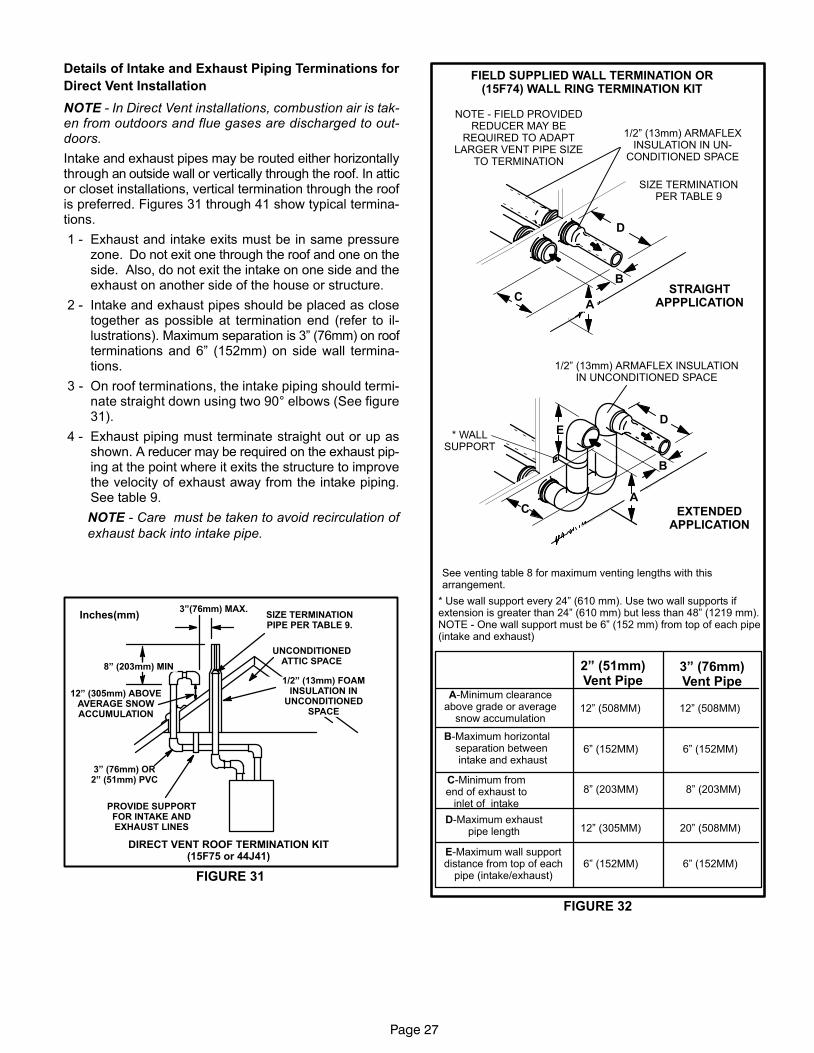
Page 27
Details of Intake and Exhaust Piping Terminations for
Direct Vent Installation
NOTE − In Direct Vent installations, combustion air is tak-en from outdoors and flue gases are discharged to out-doors.
Intake and exhaust pipes may be routed either horizontallythrough an outside wall or vertically through the roof. In atticor closet installations, vertical termination through the roofis preferred. Figures 31 through 41 show typical termina-tions.
1 − Exhaust and intake exits must be in same pressurezone. Do not exit one through the roof and one on theside. Also, do not exit the intake on one side and theexhaust on another side of the house or structure.
2 − Intake and exhaust pipes should be placed as closetogether as possible at termination end (refer to il-lustrations). Maximum separation is 3" (76mm) on roofterminations and 6" (152mm) on side wall termina-tions.
3 − On roof terminations, the intake piping should termi-nate straight down using two 90° elbows (See figure31).
4 − Exhaust piping must terminate straight out or up asshown. A reducer may be required on the exhaust pip-ing at the point where it exits the structure to improvethe velocity of exhaust away from the intake piping.See table 9.
NOTE − Care must be taken to avoid recirculation of
exhaust back into intake pipe.
FIGURE 31
UNCONDITIONEDATTIC SPACE
1/2" (13mm) FOAMINSULATION IN
UNCONDITIONEDSPACE
SIZE TERMINATIONPIPE PER TABLE 9.
3"(76mm) MAX.
12" (305mm) ABOVEAVERAGE SNOWACCUMULATION
3" (76mm) OR2" (51mm) PVC
PROVIDE SUPPORTFOR INTAKE ANDEXHAUST LINES
8" (203mm) MIN
Inches(mm)
DIRECT VENT ROOF TERMINATION KIT(15F75 or 44J41)
FIGURE 32
FIELD SUPPLIED WALL TERMINATION OR(15F74) WALL RING TERMINATION KIT
See venting table 8 for maximum venting lengths with thisarrangement.
* Use wall support every 24" (610 mm). Use two wall supports ifextension is greater than 24" (610 mm) but less than 48" (1219 mm).NOTE − One wall support must be 6" (152 mm) from top of each pipe(intake and exhaust)
2" (51mm)Vent Pipe
3" (76mm)Vent Pipe
A−Minimum clearanceabove grade or average
snow accumulation
B−Maximum horizontal separation between intake and exhaust
C−Minimum fromend of exhaust to
inlet of intake
D−Maximum exhaustpipe length
E−Maximum wall supportdistance from top of each
pipe (intake/exhaust)
12" (508MM) 12" (508MM)
6" (152MM) 6" (152MM)
8" (203MM) 8" (203MM)
12" (305MM) 20" (508MM)
6" (152MM) 6" (152MM)
NOTE − FIELD PROVIDEDREDUCER MAY BE
REQUIRED TO ADAPTLARGER VENT PIPE SIZE
TO TERMINATION
D
B
C
SIZE TERMINATIONPER TABLE 9
1/2" (13mm) ARMAFLEXINSULATION IN UN-
CONDITIONED SPACE
STRAIGHTAPPPLICATION
B
CA
D
* WALLSUPPORT
1/2" (13mm) ARMAFLEX INSULATIONIN UNCONDITIONED SPACE
E
EXTENDEDAPPLICATION
A
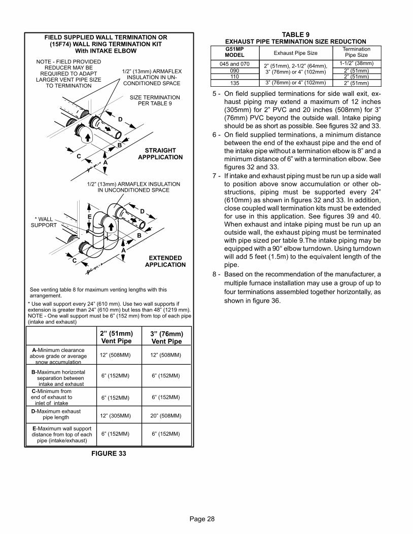
Page 28
FIGURE 33
FIELD SUPPLIED WALL TERMINATION OR(15F74) WALL RING TERMINATION KIT
With INTAKE ELBOW
See venting table 8 for maximum venting lengths with thisarrangement.
* Use wall support every 24" (610 mm). Use two wall supports ifextension is greater than 24" (610 mm) but less than 48" (1219 mm).NOTE − One wall support must be 6" (152 mm) from top of each pipe(intake and exhaust)
2" (51mm)Vent Pipe
3" (76mm)Vent Pipe
12" (508MM) 12" (508MM)
6" (152MM) 6" (152MM)
6" (152MM)
12" (305MM) 20" (508MM)
6" (152MM) 6" (152MM)
6" (152MM)
A−Minimum clearanceabove grade or average
snow accumulation
B−Maximum horizontal separation between intake and exhaust
C−Minimum fromend of exhaust to
inlet of intake
D−Maximum exhaustpipe length
E−Maximum wall supportdistance from top of each
pipe (intake/exhaust)
NOTE − FIELD PROVIDEDREDUCER MAY BE
REQUIRED TO ADAPTLARGER VENT PIPE SIZE
TO TERMINATION
D
B
C
SIZE TERMINATIONPER TABLE 9
1/2" (13mm) ARMAFLEXINSULATION IN UN-
CONDITIONED SPACE
STRAIGHTAPPPLICATION
B
C
D
* WALLSUPPORT
1/2" (13mm) ARMAFLEX INSULATIONIN UNCONDITIONED SPACE
E
EXTENDEDAPPLICATION
A
A
TABLE 9EXHAUST PIPE TERMINATION SIZE REDUCTION
G51MPMODEL Exhaust Pipe Size
TerminationPipe Size
045 and 070 2" (51mm), 2−1/2" (64mm),3" (76mm) or 4" (102mm)
1−1/2" (38mm)
090 2" (51mm)110 2" (51mm)
135 3" (76mm) or 4" (102mm) 2" (51mm)
5 − On field supplied terminations for side wall exit, ex-
haust piping may extend a maximum of 12 inches
(305mm) for 2" PVC and 20 inches (508mm) for 3"
(76mm) PVC beyond the outside wall. Intake piping
should be as short as possible. See figures 32 and 33.
6 − On field supplied terminations, a minimum distance
between the end of the exhaust pipe and the end of
the intake pipe without a termination elbow is 8" and a
minimum distance of 6" with a termination elbow. See
figures 32 and 33.
7 − If intake and exhaust piping must be run up a side wall
to position above snow accumulation or other ob-
structions, piping must be supported every 24"
(610mm) as shown in figures 32 and 33. In addition,
close coupled wall termination kits must be extended
for use in this application. See figures 39 and 40.
When exhaust and intake piping must be run up an
outside wall, the exhaust piping must be terminated
with pipe sized per table 9.The intake piping may be
equipped with a 90° elbow turndown. Using turndown
will add 5 feet (1.5m) to the equivalent length of the
pipe.
8 − Based on the recommendation of the manufacturer, a
multiple furnace installation may use a group of up to
four terminations assembled together horizontally, as
shown in figure 36.

Page 29
FIGURE 34
DIRECT VENT CONCENTRIC ROOFTOP TERMINATION71M80, 69M29 or 60L46 (US)41W92 or 41W93 (Canada)
MinimumAbove Average
SnowAccumulation
SHEET METAL STRAP(Clamp and sheet metal strap
must be field installed to supportthe weight of the termination kit.)
FLASHING(Not Furnished)
CLAMPFIELD−PROVIDED
REDUCER MAY BE REQUIREDTO ADAPT LARGER VENT
PIPE SIZE TO TERMINATION
INTAKE
1 1/2" (38mm) acceleratorprovided on 71M80 &
44W92 kits forG51MP−24B−045,
36B−045 & 36B−070
12” (305mm)
12" (305mm) Min.above grade or
average snow ac-cumulation.
FIGURE 35
DIRECT VENT CONCENTRIC WALL TERMINATION71M80, 69M29 or 60L46 (US)41W92 or 41W93 (Canada)
INTAKEAIR
EXHAUSTAIR
INTAKEAIRINTAKE
AIR
EXHAUSTAIR
OUTSIDEWALL
GRADE
CLAMP(Not Furnished)
FIELD−PROVIDEDREDUCER MAY BE
REQUIRED TO ADAPTLARGER VENT PIPE
SIZE TO TERMINATION
1 1/2" (38mm) acceleratorprovided on 71M80 &
44W92 kits forG51MP−24B−045,
36B−045 & 36B−070
FIGURE 36
EXHAUSTVENT
INTAKEAIR
5−1/2"(140mm)
Front View
12"(305mm)
5"(127mm)
18" MAX.(457mm)
EXHAUST VENT
INTAKEAIR
OPTIONAL VENT TERMINATION FOR MULTIPLE UNITINSTALLATION OF DIRECT VENT WALL TERMINATION KIT
(22G44, 44J40, 30G28 or 81J20)
Inches (mm)
Side View
12" (305mm) Min.above grade or
average snow ac-cumulation.
optional intake elbow
FIGURE 37
1/2" (13mm) Foam Insulation in Unconditioned Space
EXHAUST VENT
INTAKE AIR
OUTSIDE WALL
EXHAUST VENT
INTAKEAIR
Front View
Top View
DIRECT VENT WALL TERMINATION KIT(30G28 or 81J20)
6 (152mm) MIN.
SIZETERMINATION
PIPE PERTABLE 9.
FIELD−PROVIDEDREDUCER MAY
BE REQUIRED TOADAPT LARGERVENT PIPE SIZE
TO TERMINATION
FIGURE 38
1/2" (13mm) Foam Insulation in Unconditioned Space
EXHAUST VENT
INTAKE AIR
OUTSIDE WALL
EXHAUST VENT
INTAKEAIR
Front View
Top View
DIRECT VENT WALL TERMINATION KIT(22G44 or 44J40)
8" (206mm) MIN.
SIZETERMINATION
PIPE PERTABLE 9.
FIELD−PROVIDEDREDUCER MAY
BE REQUIRED TOADAPT LARGERVENT PIPE SIZE
TO TERMINATION
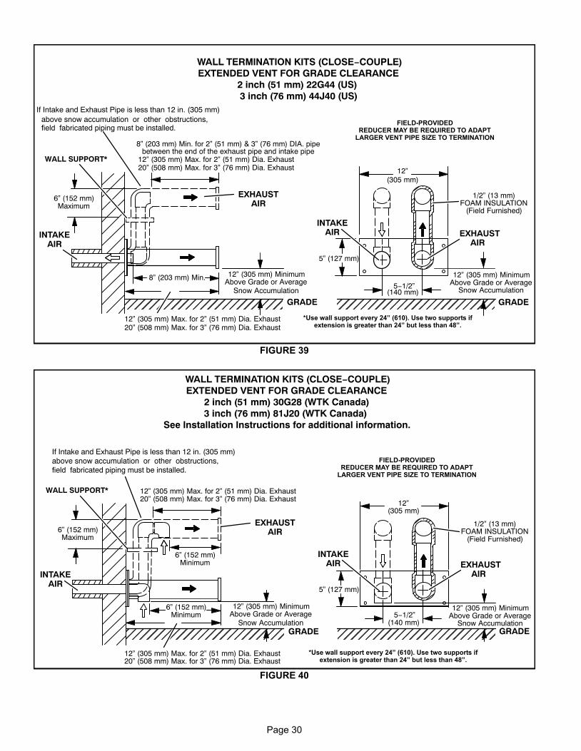
Page 30
FIGURE 39
ÉÉÉÉÉÉÉÉÉÉÉÉÉÉÉÉÉÉÉÉÉÉÉÉ
ÉÉÉÉÉÉÉÉÉÉÉÉÉÉÉÉÉÉÉÉÉÉ
12” (305 mm) MinimumAbove Grade or Average
Snow Accumulation
1/2” (13 mm)FOAM INSULATION
(Field Furnished)
5” (127 mm)
5−1/2”(140 mm)
EXHAUSTAIR
INTAKEAIR
GRADE
12”(305 mm)
INTAKEAIR
EXHAUSTAIR
GRADE
12” (305 mm) Max. for 2” (51 mm) Dia. Exhaust20” (508 mm) Max. for 3” (76 mm) Dia. Exhaust
WALL SUPPORT*
12” (305 mm) Max. for 2” (51 mm) Dia. Exhaust20” (508 mm) Max. for 3” (76 mm) Dia. Exhaust
12” (305 mm) MinimumAbove Grade or Average
Snow Accumulation
WALL TERMINATION KITS (CLOSE−COUPLE)EXTENDED VENT FOR GRADE CLEARANCE
2 inch (51 mm) 22G44 (US)3 inch (76 mm) 44J40 (US)
6” (152 mm)Maximum
If Intake and Exhaust Pipe is less than 12 in. (305 mm)above snow accumulation or other obstructions,field fabricated piping must be installed.
8” (203 mm) Min. for 2” (51 mm) & 3” (76 mm) DIA. pipebetween the end of the exhaust pipe and intake pipe
8” (203 mm) Min.
*Use wall support every 24" (610). Use two supports ifextension is greater than 24" but less than 48".
FIELD−PROVIDEDREDUCER MAY BE REQUIRED TO ADAPT
LARGER VENT PIPE SIZE TO TERMINATION
FIGURE 40
ÉÉÉÉÉÉÉÉÉÉÉÉ
12” (305 mm) MinimumAbove Grade or Average
Snow Accumulation
1/2” (13 mm)FOAM INSULATION
(Field Furnished)
5” (127 mm)
5−1/2”(140 mm)
EXHAUSTAIR
INTAKEAIR
GRADE
12”(305 mm)
INTAKEAIR
EXHAUSTAIR
GRADE
WALL SUPPORT*
12” (305 mm) MinimumAbove Grade or Average
Snow Accumulation
WALL TERMINATION KITS (CLOSE−COUPLE)EXTENDED VENT FOR GRADE CLEARANCE
2 inch (51 mm) 30G28 (WTK Canada)3 inch (76 mm) 81J20 (WTK Canada)
See Installation Instructions for additional information.
6” (152 mm)Maximum
If Intake and Exhaust Pipe is less than 12 in. (305 mm)above snow accumulation or other obstructions,field fabricated piping must be installed.
12” (305 mm) Max. for 2” (51 mm) Dia. Exhaust20” (508 mm) Max. for 3” (76 mm) Dia. Exhaust
12” (305 mm) Max. for 2” (51 mm) Dia. Exhaust20” (508 mm) Max. for 3” (76 mm) Dia. Exhaust
6” (152 mm)Minimum
6” (152 mm)Minimum
*Use wall support every 24" (610). Use two supports ifextension is greater than 24" but less than 48".
FIELD−PROVIDEDREDUCER MAY BE REQUIRED TO ADAPT
LARGER VENT PIPE SIZE TO TERMINATION
ÉÉÉÉÉÉÉÉÉÉÉ
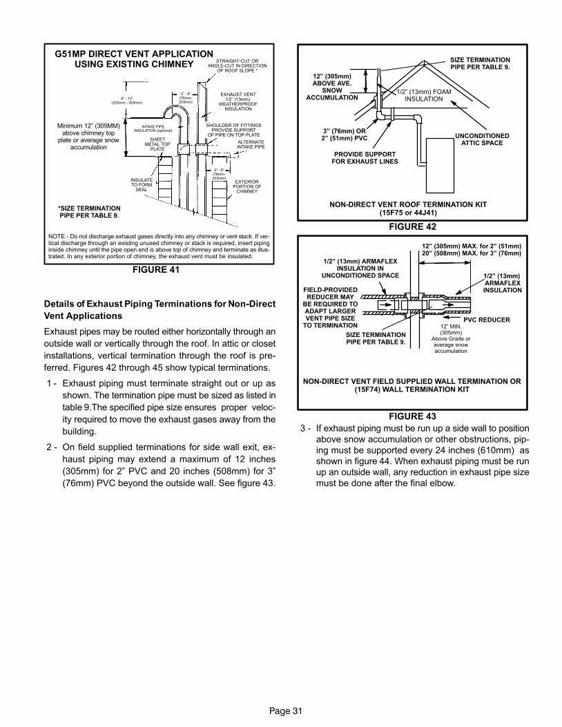
Page 31
G51MP DIRECT VENT APPLICATIONUSING EXISTING CHIMNEY
NOTE − Do not discharge exhaust gases directly into any chimney or vent stack. If ver-tical discharge through an existing unused chimney or stack is required, insert pipinginside chimney until the pipe open end is above top of chimney and terminate as illus-trated. In any exterior portion of chimney, the exhaust vent must be insulated.
FIGURE 41
8" − 12"(203mm − 305mm)
3" − 8"(76mm−203mm)
3" − 8"(76mm−203mm)
STRAIGHT−CUT ORANGLE−CUT IN DIRECTION
OF ROOF SLOPE *
EXHAUST VENT1/2" (13mm)
WEATHERPROOFINSULATION
SHOULDER OF FITTINGSPROVIDE SUPPORT
OF PIPE ON TOP PLATE
ALTERNATEINTAKE PIPE
INTAKE PIPEINSULATION (optional)
EXTERIORPORTION OF
CHIMNEY
INSULATETO FORM
SEAL
SHEETMETAL TOP
PLATE
*SIZE TERMINATIONPIPE PER TABLE 9.
Minimum 12" (305MM)above chimney top
plate or average snowaccumulation
Details of Exhaust Piping Terminations for Non-Direct
Vent Applications
Exhaust pipes may be routed either horizontally through an
outside wall or vertically through the roof. In attic or closet
installations, vertical termination through the roof is pre-
ferred. Figures 42 through 45 show typical terminations.
1 − Exhaust piping must terminate straight out or up as
shown. The termination pipe must be sized as listed in
table 9.The specified pipe size ensures proper veloc-
ity required to move the exhaust gases away from the
building.
2 − On field supplied terminations for side wall exit, ex-
haust piping may extend a maximum of 12 inches
(305mm) for 2" PVC and 20 inches (508mm) for 3"
(76mm) PVC beyond the outside wall. See figure 43.
FIGURE 42
NON−DIRECT VENT ROOF TERMINATION KIT(15F75 or 44J41)
UNCONDITIONEDATTIC SPACE
3" (76mm) OR2" (51mm) PVC
PROVIDE SUPPORTFOR EXHAUST LINES
12" (305mm)ABOVE AVE.
SNOWACCUMULATION
SIZE TERMINATIONPIPE PER TABLE 9.
1/2" (13mm) FOAMINSULATION
FIGURE 43
1/2" (13mm) ARMAFLEXINSULATION IN
UNCONDITIONED SPACE
PVC REDUCER
1/2" (13mm) ARMAFLEXINSULATION
NON−DIRECT VENT FIELD SUPPLIED WALL TERMINATION OR(15F74) WALL TERMINATION KIT
SIZE TERMINATIONPIPE PER TABLE 9.
FIELD−PROVIDEDREDUCER MAY
BE REQUIRED TOADAPT LARGERVENT PIPE SIZE
TO TERMINATION 12" MIN.(305mm)
Above Grade oraverage snowaccumulation
12" (305mm) MAX. for 2" (51mm)20" (508mm) MAX. for 3" (76mm)
3 − If exhaust piping must be run up a side wall to position
above snow accumulation or other obstructions, pip-
ing must be supported every 24 inches (610mm) as
shown in figure 44. When exhaust piping must be run
up an outside wall, any reduction in exhaust pipe size
must be done after the final elbow.
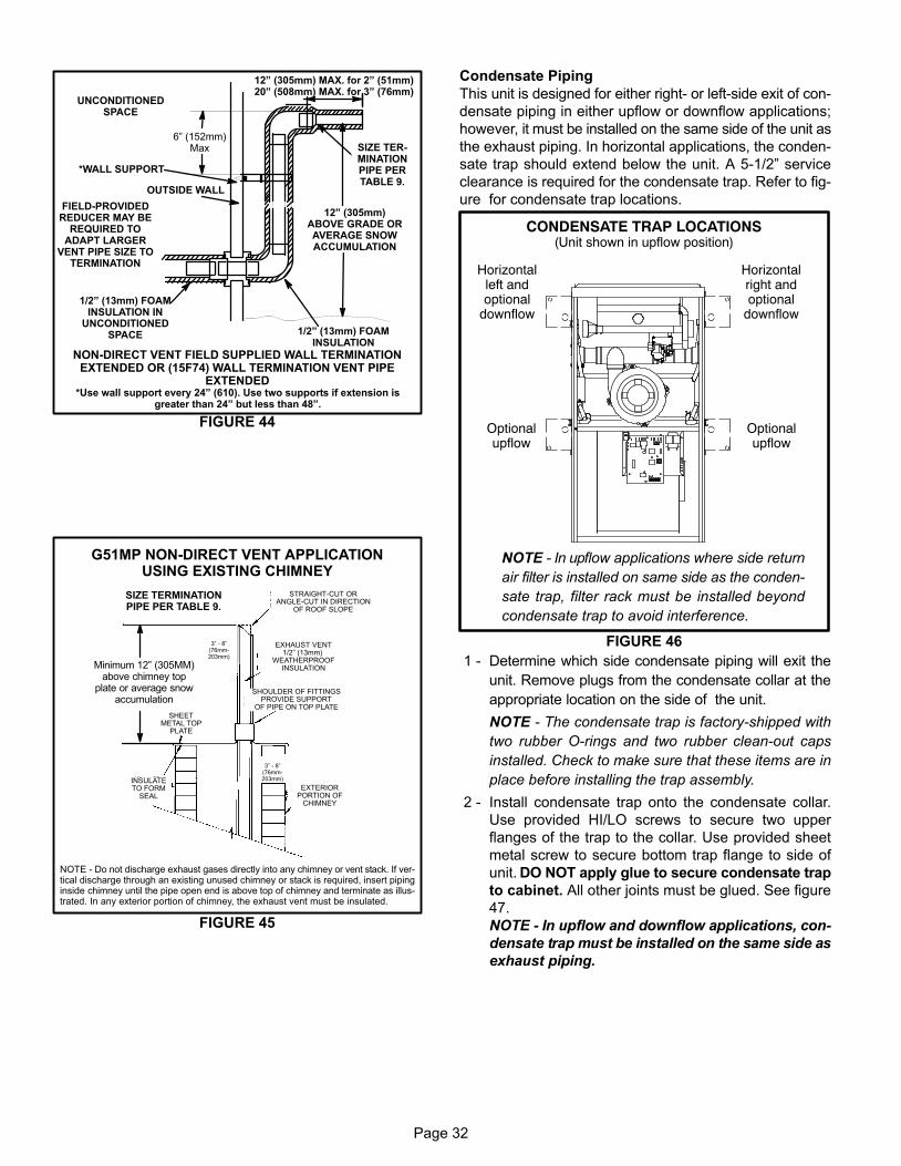
Page 32
FIGURE 44
12" (305mm)ABOVE GRADE ORAVERAGE SNOWACCUMULATION
UNCONDITIONEDSPACE
1/2" (13mm) FOAMINSULATION
1/2" (13mm) FOAMINSULATION IN
UNCONDITIONEDSPACE
*WALL SUPPORT
OUTSIDE WALL
SIZE TER-MINATIONPIPE PERTABLE 9.
FIELD−PROVIDEDREDUCER MAY BE
REQUIRED TOADAPT LARGER
VENT PIPE SIZE TOTERMINATION
*Use wall support every 24" (610). Use two supports if extension isgreater than 24" but less than 48".
12" (305mm) MAX. for 2" (51mm)20" (508mm) MAX. for 3" (76mm)
NON−DIRECT VENT FIELD SUPPLIED WALL TERMINATIONEXTENDED OR (15F74) WALL TERMINATION VENT PIPE
EXTENDED
6" (152mm)Max
NOTE − Do not discharge exhaust gases directly into any chimney or vent stack. If ver-tical discharge through an existing unused chimney or stack is required, insert pipinginside chimney until the pipe open end is above top of chimney and terminate as illus-trated. In any exterior portion of chimney, the exhaust vent must be insulated.
FIGURE 45
3" − 8"(76mm−203mm)
3" − 8"(76mm−203mm)
STRAIGHT−CUT ORANGLE−CUT IN DIRECTION
OF ROOF SLOPE
EXHAUST VENT1/2" (13mm)
WEATHERPROOFINSULATION
SHOULDER OF FITTINGSPROVIDE SUPPORT
OF PIPE ON TOP PLATE
EXTERIORPORTION OF
CHIMNEY
INSULATETO FORM
SEAL
SHEETMETAL TOP
PLATE
SIZE TERMINATIONPIPE PER TABLE 9.
G51MP NON−DIRECT VENT APPLICATIONUSING EXISTING CHIMNEY
Minimum 12" (305MM)above chimney top
plate or average snowaccumulation
Condensate Piping
This unit is designed for either right- or left-side exit of con-
densate piping in either upflow or downflow applications;
however, it must be installed on the same side of the unit as
the exhaust piping. In horizontal applications, the conden-
sate trap should extend below the unit. A 5−1/2" service
clearance is required for the condensate trap. Refer to fig-
ure for condensate trap locations.
FIGURE 46
CONDENSATE TRAP LOCATIONS(Unit shown in upflow position)
Horizontalleft andoptional
downflow
Horizontalright andoptional
downflow
Optionalupflow
Optionalupflow
NOTE − In upflow applications where side return
air filter is installed on same side as the conden-
sate trap, filter rack must be installed beyond
condensate trap to avoid interference.
1 − Determine which side condensate piping will exit the
unit. Remove plugs from the condensate collar at the
appropriate location on the side of the unit.
NOTE − The condensate trap is factory−shipped with
two rubber O−rings and two rubber clean−out caps
installed. Check to make sure that these items are in
place before installing the trap assembly.
2 − Install condensate trap onto the condensate collar.
Use provided HI/LO screws to secure two upper
flanges of the trap to the collar. Use provided sheet
metal screw to secure bottom trap flange to side of
unit. DO NOT apply glue to secure condensate trap
to cabinet. All other joints must be glued. See figure
47.
NOTE − In upflow and downflow applications, con-
densate trap must be installed on the same side as
exhaust piping.
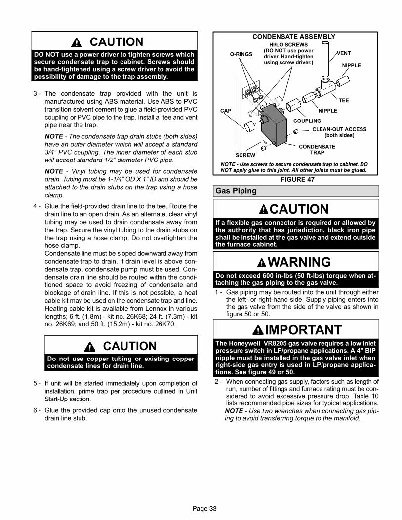
Page 33
CAUTIONDO NOT use a power driver to tighten screws whichsecure condensate trap to cabinet. Screws shouldbe hand−tightened using a screw driver to avoid thepossibility of damage to the trap assembly.
3 − The condensate trap provided with the unit is
manufactured using ABS material. Use ABS to PVC
transition solvent cement to glue a field−provided PVC
coupling or PVC pipe to the trap. Install a tee and vent
pipe near the trap.
NOTE − The condensate trap drain stubs (both sides)
have an outer diameter which will accept a standard
3/4" PVC coupling. The inner diameter of each stub
will accept standard 1/2" diameter PVC pipe.
NOTE − Vinyl tubing may be used for condensate
drain. Tubing must be 1−1/4" OD X 1" ID and should be
attached to the drain stubs on the trap using a hose
clamp.
4 − Glue the field−provided drain line to the tee. Route the
drain line to an open drain. As an alternate, clear vinyl
tubing may be used to drain condensate away from
the trap. Secure the vinyl tubing to the drain stubs on
the trap using a hose clamp. Do not overtighten the
hose clamp.
Condensate line must be sloped downward away from
condensate trap to drain. If drain level is above con-
densate trap, condensate pump must be used. Con-
densate drain line should be routed within the condi-
tioned space to avoid freezing of condensate and
blockage of drain line. If this is not possible, a heat
cable kit may be used on the condensate trap and line.
Heating cable kit is available from Lennox in various
lengths; 6 ft. (1.8m) − kit no. 26K68; 24 ft. (7.3m) − kit
no. 26K69; and 50 ft. (15.2m) − kit no. 26K70.
CAUTIONDo not use copper tubing or existing coppercondensate lines for drain line.
5 − If unit will be started immediately upon completion of
installation, prime trap per procedure outlined in Unit
Start−Up section.
6 − Glue the provided cap onto the unused condensate
drain line stub.
CONDENSATE ASSEMBLY
FIGURE 47
COUPLING
CAP
CONDENSATETRAP
NIPPLE
NIPPLE
TEE
VENT
CLEAN−OUT ACCESS(both sides)
HI/LO SCREWS(DO NOT use powerdriver. Hand−tightenusing screw driver.)
SCREW
O−RINGS
NOTE − Use screws to secure condensate trap to cabinet. DONOT apply glue to this joint. All other joints must be glued.
Gas Piping
CAUTIONIf a flexible gas connector is required or allowed bythe authority that has jurisdiction, black iron pipeshall be installed at the gas valve and extend outsidethe furnace cabinet.
WARNINGDo not exceed 600 in−lbs (50 ft−lbs) torque when at-taching the gas piping to the gas valve.
1 − Gas piping may be routed into the unit through eitherthe left- or right-hand side. Supply piping enters intothe gas valve from the side of the valve as shown infigure 50 or 50.
IMPORTANTThe Honeywell VR8205 gas valve requires a low inletpressure switch in LP/propane applications. A 4" BIPnipple must be installed in the gas valve inlet whenright−side gas entry is used in LP/propane applica-tions. See figure 49 or 50.
2 − When connecting gas supply, factors such as length ofrun, number of fittings and furnace rating must be con-sidered to avoid excessive pressure drop. Table 10lists recommended pipe sizes for typical applications.
NOTE − Use two wrenches when connecting gas pip-ing to avoid transferring torque to the manifold.
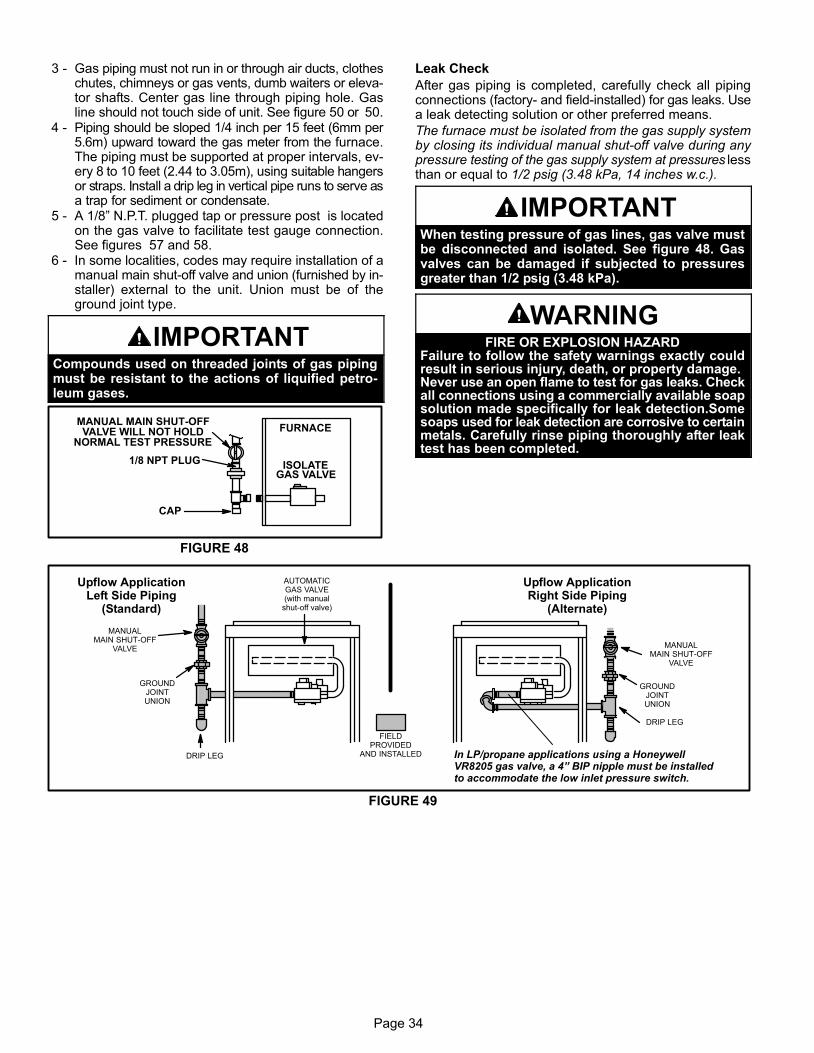
Page 34
3 − Gas piping must not run in or through air ducts, clotheschutes, chimneys or gas vents, dumb waiters or eleva-tor shafts. Center gas line through piping hole. Gasline should not touch side of unit. See figure 50 or 50.
4 − Piping should be sloped 1/4 inch per 15 feet (6mm per5.6m) upward toward the gas meter from the furnace.The piping must be supported at proper intervals, ev-ery 8 to 10 feet (2.44 to 3.05m), using suitable hangersor straps. Install a drip leg in vertical pipe runs to serve asa trap for sediment or condensate.
5 − A 1/8" N.P.T. plugged tap or pressure post is locatedon the gas valve to facilitate test gauge connection.See figures 57 and 58.
6 − In some localities, codes may require installation of amanual main shut-off valve and union (furnished by in-staller) external to the unit. Union must be of theground joint type.
IMPORTANTCompounds used on threaded joints of gas pipingmust be resistant to the actions of liquified petro-leum gases.
FIGURE 48
MANUAL MAIN SHUT−OFFVALVE WILL NOT HOLD
NORMAL TEST PRESSURE
CAP
FURNACE
ISOLATEGAS VALVE
1/8 NPT PLUG
Leak Check
After gas piping is completed, carefully check all pipingconnections (factory− and field−installed) for gas leaks. Usea leak detecting solution or other preferred means.
The furnace must be isolated from the gas supply systemby closing its individual manual shut-off valve during anypressure testing of the gas supply system at pressures lessthan or equal to 1/2 psig (3.48 kPa, 14 inches w.c.).
IMPORTANTWhen testing pressure of gas lines, gas valve mustbe disconnected and isolated. See figure 48. Gasvalves can be damaged if subjected to pressuresgreater than 1/2 psig (3.48 kPa).
WARNINGFIRE OR EXPLOSION HAZARD
Failure to follow the safety warnings exactly couldresult in serious injury, death, or property damage.Never use an open flame to test for gas leaks. Checkall connections using a commercially available soapsolution made specifically for leak detection.Somesoaps used for leak detection are corrosive to certainmetals. Carefully rinse piping thoroughly after leaktest has been completed.
GROUNDJOINTUNION
AUTOMATICGAS VALVE(with manual
shut−off valve)
FIELDPROVIDED
AND INSTALLED
Upflow ApplicationLeft Side Piping
(Standard)
DRIP LEG
MANUALMAIN SHUT−OFF
VALVE
GROUNDJOINTUNION
DRIP LEG
MANUALMAIN SHUT−OFF
VALVE
Upflow ApplicationRight Side Piping
(Alternate)
In LP/propane applications using a HoneywellVR8205 gas valve, a 4" BIP nipple must be installedto accommodate the low inlet pressure switch.
FIGURE 49
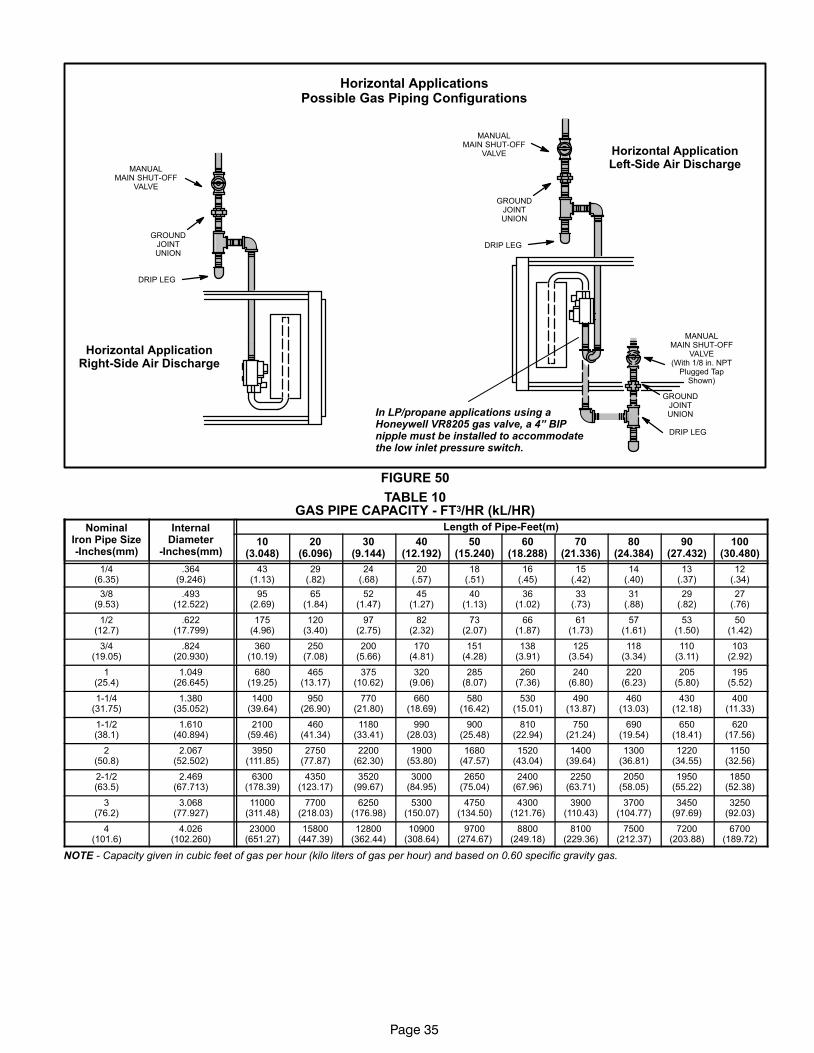
Page 35
GROUNDJOINTUNION
DRIP LEG
MANUALMAIN SHUT−OFF
VALVE
GROUNDJOINTUNION
DRIP LEG
MANUALMAIN SHUT−OFF
VALVE(With 1/8 in. NPT
Plugged TapShown)
GROUNDJOINTUNION
DRIP LEG
MANUALMAIN SHUT−OFF
VALVE
Horizontal ApplicationsPossible Gas Piping Configurations
Horizontal ApplicationLeft−Side Air Discharge
Horizontal ApplicationRight−Side Air Discharge
In LP/propane applications using aHoneywell VR8205 gas valve, a 4" BIPnipple must be installed to accommodatethe low inlet pressure switch.
FIGURE 50
TABLE 10GAS PIPE CAPACITY − FT3/HR (kL/HR)
NominalIron Pipe Size−Inches(mm)
InternalDiameter
−Inches(mm)
Length of Pipe−Feet(m)
10(3.048)
20(6.096)
30(9.144)
40(12.192)
50(15.240)
60(18.288)
70(21.336)
80(24.384)
90(27.432)
100(30.480)
1/4(6.35)
.364(9.246)
43(1.13)
29(.82)
24(.68)
20(.57)
18(.51)
16(.45)
15(.42)
14(.40)
13(.37)
12(.34)
3/8(9.53)
.493(12.522)
95(2.69)
65(1.84)
52(1.47)
45(1.27)
40(1.13)
36(1.02)
33(.73)
31(.88)
29(.82)
27(.76)
1/2(12.7)
.622(17.799)
175(4.96)
120(3.40)
97(2.75)
82(2.32)
73(2.07)
66(1.87)
61(1.73)
57(1.61)
53(1.50)
50(1.42)
3/4(19.05)
.824(20.930)
360(10.19)
250(7.08)
200(5.66)
170(4.81)
151(4.28)
138(3.91)
125(3.54)
118(3.34)
110(3.11)
103(2.92)
1(25.4)
1.049(26.645)
680(19.25)
465(13.17)
375(10.62)
320(9.06)
285(8.07)
260(7.36)
240(6.80)
220(6.23)
205(5.80)
195(5.52)
1−1/4(31.75)
1.380(35.052)
1400(39.64)
950(26.90)
770(21.80)
660(18.69)
580(16.42)
530(15.01)
490(13.87)
460(13.03)
430(12.18)
400(11.33)
1−1/2(38.1)
1.610(40.894)
2100(59.46)
460(41.34)
1180(33.41)
990(28.03)
900(25.48)
810(22.94)
750(21.24)
690(19.54)
650(18.41)
620(17.56)
2(50.8)
2.067(52.502)
3950(111.85)
2750(77.87)
2200(62.30)
1900(53.80)
1680(47.57)
1520(43.04)
1400(39.64)
1300(36.81)
1220(34.55)
1150(32.56)
2−1/2(63.5)
2.469(67.713)
6300(178.39)
4350(123.17)
3520(99.67)
3000(84.95)
2650(75.04)
2400(67.96)
2250(63.71)
2050(58.05)
1950(55.22)
1850(52.38)
3(76.2)
3.068(77.927)
11000(311.48)
7700(218.03)
6250(176.98)
5300(150.07)
4750(134.50)
4300(121.76)
3900(110.43)
3700(104.77)
3450(97.69)
3250(92.03)
4(101.6)
4.026(102.260)
23000(651.27)
15800(447.39)
12800(362.44)
10900(308.64)
9700(274.67)
8800(249.18)
8100(229.36)
7500(212.37)
7200(203.88)
6700(189.72)
NOTE − Capacity given in cubic feet of gas per hour (kilo liters of gas per hour) and based on 0.60 specific gravity gas.
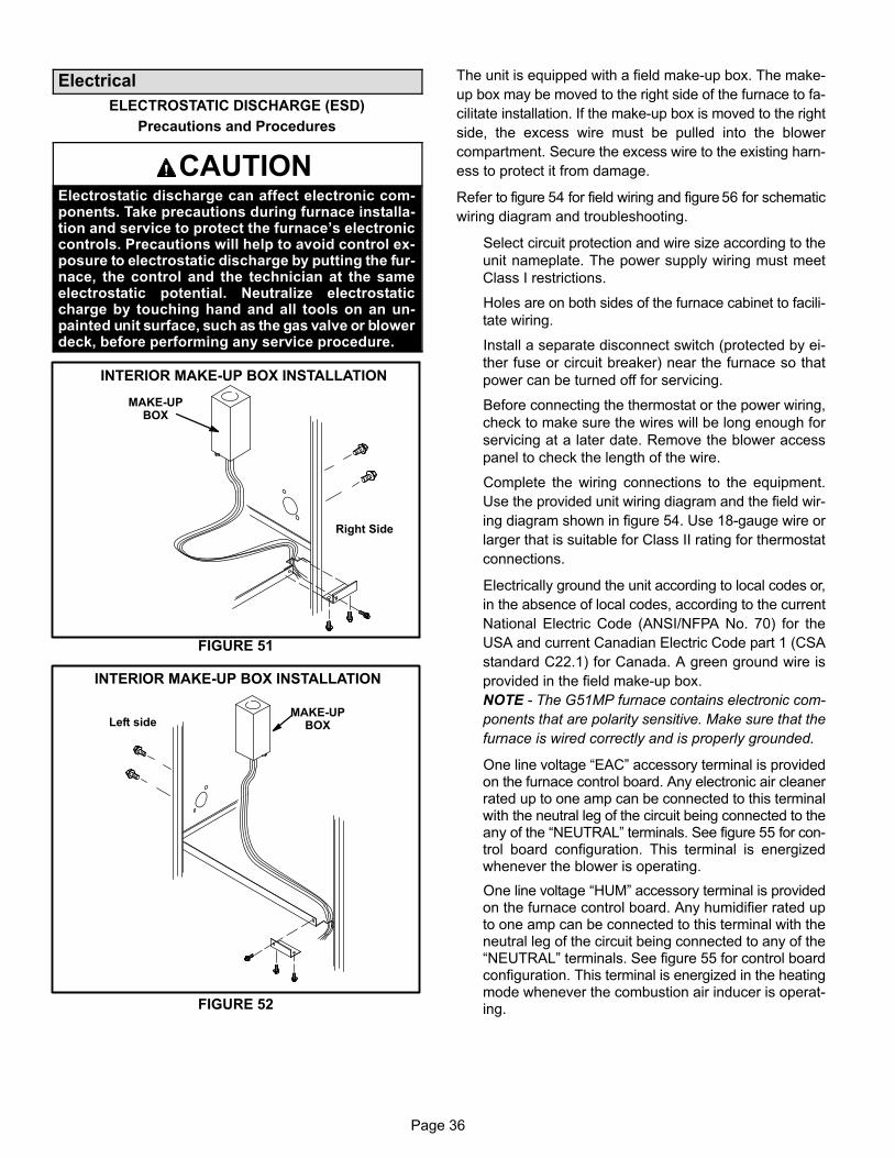
Page 36
Electrical
ELECTROSTATIC DISCHARGE (ESD)
Precautions and Procedures
CAUTIONElectrostatic discharge can affect electronic com-ponents. Take precautions during furnace installa-tion and service to protect the furnace’s electroniccontrols. Precautions will help to avoid control ex-posure to electrostatic discharge by putting the fur-nace, the control and the technician at the sameelectrostatic potential. Neutralize electrostaticcharge by touching hand and all tools on an un-painted unit surface, such as the gas valve or blowerdeck, before performing any service procedure.
INTERIOR MAKE−UP BOX INSTALLATION
MAKE−UPBOX
Right Side
FIGURE 51
INTERIOR MAKE−UP BOX INSTALLATION
MAKE−UPBOXLeft side
FIGURE 52
The unit is equipped with a field make−up box. The make−
up box may be moved to the right side of the furnace to fa-
cilitate installation. If the make−up box is moved to the right
side, the excess wire must be pulled into the blower
compartment. Secure the excess wire to the existing harn-
ess to protect it from damage.
Refer to figure 54 for field wiring and figure 56 for schematic
wiring diagram and troubleshooting.
Select circuit protection and wire size according to the
unit nameplate. The power supply wiring must meet
Class I restrictions.
Holes are on both sides of the furnace cabinet to facili-
tate wiring.
Install a separate disconnect switch (protected by ei-
ther fuse or circuit breaker) near the furnace so that
power can be turned off for servicing.
Before connecting the thermostat or the power wiring,
check to make sure the wires will be long enough for
servicing at a later date. Remove the blower access
panel to check the length of the wire.
Complete the wiring connections to the equipment.
Use the provided unit wiring diagram and the field wir-
ing diagram shown in figure 54. Use 18−gauge wire or
larger that is suitable for Class II rating for thermostat
connections.
Electrically ground the unit according to local codes or,
in the absence of local codes, according to the current
National Electric Code (ANSI/NFPA No. 70) for the
USA and current Canadian Electric Code part 1 (CSA
standard C22.1) for Canada. A green ground wire is
provided in the field make−up box.
NOTE − The G51MP furnace contains electronic com-
ponents that are polarity sensitive. Make sure that the
furnace is wired correctly and is properly grounded.
One line voltage �EAC" accessory terminal is providedon the furnace control board. Any electronic air cleanerrated up to one amp can be connected to this terminalwith the neutral leg of the circuit being connected to theany of the �NEUTRAL" terminals. See figure 55 for con-trol board configuration. This terminal is energizedwhenever the blower is operating.
One line voltage �HUM" accessory terminal is providedon the furnace control board. Any humidifier rated upto one amp can be connected to this terminal with theneutral leg of the circuit being connected to any of the�NEUTRAL" terminals. See figure 55 for control boardconfiguration. This terminal is energized in the heatingmode whenever the combustion air inducer is operat-ing.
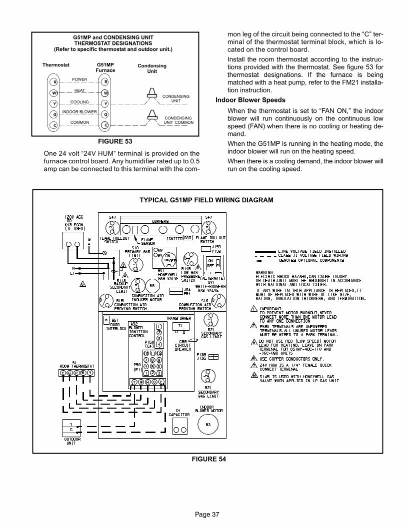
Page 37
Thermostat G51MPFurnace
CondensingUnit
G51MP and CONDENSING UNITTHERMOSTAT DESIGNATIONS
(Refer to specific thermostat and outdoor unit.)
COMMON
POWER
HEAT
INDOOR BLOWER
Y
C
R
G
W1
Y
C
R
G
W
COOLING
FIGURE 53
CONDENSINGUNIT�
CONDENSINGUNIT� COMMON
One 24 volt �24V HUM" terminal is provided on thefurnace control board. Any humidifier rated up to 0.5amp can be connected to this terminal with the com-
mon leg of the circuit being connected to the �C" ter-minal of the thermostat terminal block, which is lo-cated on the control board.
Install the room thermostat according to the instruc-tions provided with the thermostat. See figure 53 forthermostat designations. If the furnace is beingmatched with a heat pump, refer to the FM21 installa-tion instruction.
Indoor Blower Speeds
When the thermostat is set to �FAN ON," the indoorblower will run continuously on the continuous lowspeed (FAN) when there is no cooling or heating de-mand.
When the G51MP is running in the heating mode, theindoor blower will run on the heating speed.
When there is a cooling demand, the indoor blower willrun on the cooling speed.
TYPICAL G51MP FIELD WIRING DIAGRAM
FIGURE 54

Page 38
FIGURE 55
COOL
HEAT
PARK
FAN
EAC
XFMR
LINE
HUM
5 Terminals
FS
24V HUM
Blower − Cooling Speed (120VAC)
Blower − Heating Speed (120VAC)
Unused Blower (Not energized)
Continuous Low Blower Speed
Accessory Terminal (120VAC)
Transformer (120VAC)
Input (120VAC)
Heat Only Accessory (120VAC)
120 Volt Neutral
Flame Sensor
Heat Only Accessory (24VAC)
SURELIGHT® INTEGRATED CONTROL BOARD
TERMINAL DESIGNATIONS
1/4" FEMALEQUICK
CONNECT*
*
*Factory setting
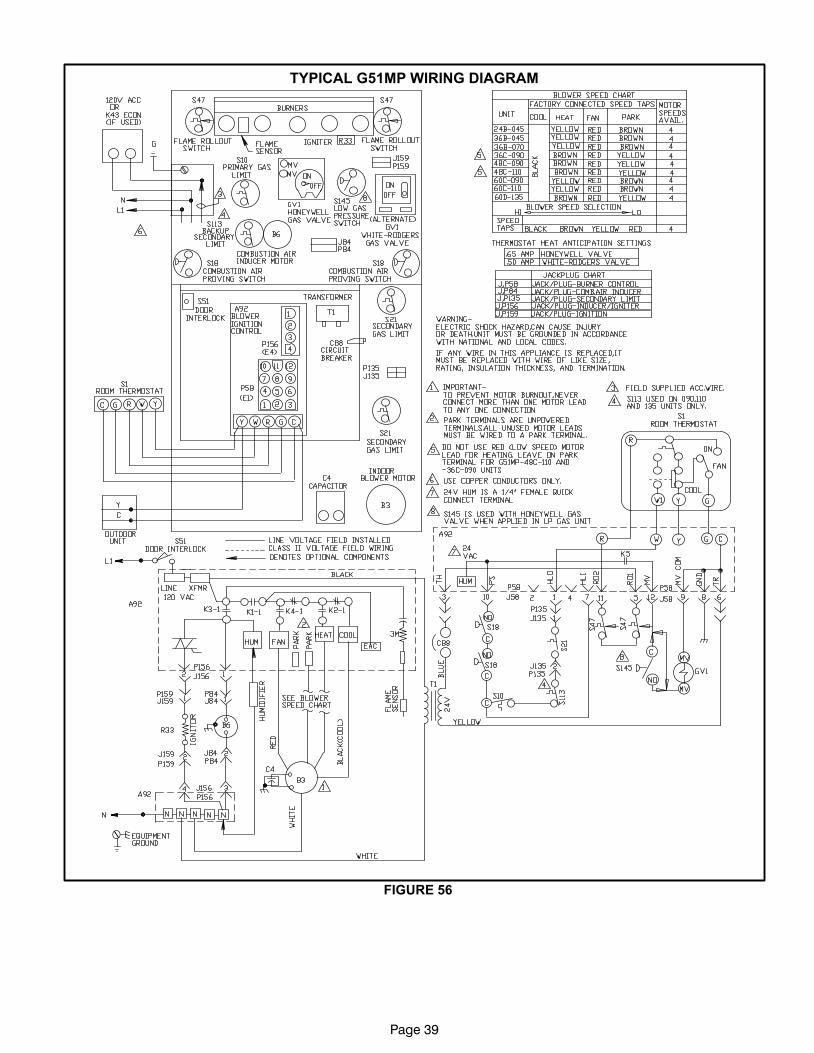
Page 39
FIGURE 56
TYPICAL G51MP WIRING DIAGRAM

Page 40
Unit Start−Up
FOR YOUR SAFETY READ BEFORE OPERATING
WARNINGDo not use this furnace if any part has been under-water. A flood−damaged furnace is extremely dan-gerous. Attempts to use the furnace can result infire or explosion. Immediately call a qualified ser-vice technician to inspect the furnace and to replaceall gas controls, control system parts, and electricalparts that have been wet or to replace the furnace,if deemed necessary.
WARNINGDanger of explosion. Can cause injuryor product or property damage. Shouldthe gas supply fail to shut off or ifoverheating occurs, shut off the gasvalve to the furnace before shutting offthe electrical supply.
CAUTIONBefore attempting to perform any service or mainte-nance, turn the electrical power to unit OFF at dis-connect switch.
Priming Condensate Trap
The condensate trap should be primed with water prior to
start−up to ensure proper condensate drainage. Either
pour 10 fl. oz. (300 ml) of water into the trap, or follow
these steps to prime the trap:
1 − Follow the lighting instructions to place the unit into op-
eration.
2 − Set the thermostat to initiate a heating demand.
3 − Allow the burners to fire for approximately 3 minutes.
4 − Adjust the thermostat to deactivate the heating de-
mand.
5 − Wait for the combustion air inducer to stop. Set the
thermostat to initiate a heating demand and again al-
low the burners to fire for approximately 3 minutes.
6 − Adjust the thermostat to deactivate the heating de-
mand and again wait for the combustion air inducer to
stop. At this point, the trap should be primed with suffi-
cient water to ensure proper condensate drain opera-
tion.
BEFORE LIGHTING the unit, smell all around the fur-
nace area for gas. Be sure to smell next to the floor be-
cause some gas is heavier than air and will settle on the
floor.
The gas valve on the G51MP is equipped with a gas con-
trol switch (lever). Use only your hand to move the switch.
Never use tools. If the the switch will not move by hand,
do not try to repair it. Force or attempted repair may result
in a fire or explosion.
Placing the furnace into operation:
G51MP units are equipped with a SureLight® ignition
system. Do not attempt to manually light burners on this
furnace. Each time the thermostat calls for heat, the
burners will automatically light. The ignitor does not get
hot when there is no call for heat on units with SureLight®
ignition system.
WARNINGIf you do not follow these instructions exactly, a fireor explosion may result causing property damage,personal injury or death.
Gas Valve Operation (Figures 57 and 58)
1 − STOP! Read the safety information at the beginning of
this section.
2 − Set the thermostat to the lowest setting.
3 − Turn off all electrical power to the unit.
4 − This furnace is equipped with an ignition device which
automatically lights the burners. Do not try to light the
burners by hand.
5 − Remove the upper access panel.
6 − White Rodgers 36G Gas Valve − Move gas valve
switch to OFF. See figure 57 for the White Rodgers
36G valve.
Honeywell VR8205 Gas Valve − Move gas valve
switch to OFF. See figure 58 for Honeywell VR8205
valve.
7 − Wait five minutes to clear out any gas. If you then smell
gas, STOP! Immediately call your gas supplier from a
neighbor’s phone. Follow the gas supplier’s instruc-
tions. If you do not smell gas go to next step.

Page 41
White Rodgers 36G Series Gas Valve
GAS VALVE SHOWN IN OFF POSITION
MANIFOLDPRESSURE
ADJUSTMENTSCREW
OUTLETPRESSURE
POST
INLETPRESSURE
POST
FIGURE 57
GAS VALVE SHOWN IN ON POSITION
Honeywell VR8205 Gas Valve with ON/OFF Switch
MANIFOLDPRESSURE
OUTLET
INLETPRESSURE
PORT
MANIFOLDPRESSURE
ADJUSTMENTSCREW(underbarbedfitting)
FIGURE 58
8 − White Rodgers 36G Gas Valve − Move gas valve
switch to ON. See figure 57 for the White Rodgers
36G valve
Honeywell VR8205 Gas Valve − Move gas valve
switch to ON. See figure 58 for Honeywell VR8205
valve.
9 − Replace the upper access panel.
10− Turn on all electrical power to to the unit.
11− Set the thermostat to desired setting.
NOTE − When unit is initially started, steps 1 through 11
may need to be repeated to purge air from gas line.
12− If the appliance will not operate, follow the instructions
�Turning Off Gas to Unit" and call the gas supplier.
Turning Off Gas to Unit
1 − Set the thermostat to the lowest setting.
2 − Turn off all electrical power to the unit if service is to be
performed.
3 − Remove the upper access panel.
4 − White Rodgers 36G Gas Valve − Move gas valve
switch to OFF.
Honeywell VR8205 Gas Valve − Move gas valve
switch to OFF.
5 − Replace the upper access panel.
Heating Sequence Of Operation
When thermostat calls for heat, combustion air inducer
starts.
Combustion air pressure switch proves blower opera-
tion. Switch is factory set and requires no adjustment.
After a 15−second prepurge, the hot surface ignitor en-
ergizes.
After a 20−second ignitor warm−up period, the gas
valve solenoid opens.
Gas is ignited, flame sensor proves the flame, and the
combustion process continues.
If flame is not detected after first ignition trial, the igni-
tion control will repeat steps 3 and 4 four more times
before locking out the gas valve (�WATCHGUARD"
flame failure mode). The ignition control will then auto-
matically repeat steps 1 through 6 after 60 minutes.
To interrupt the 60−minute �WATCHGUARD" period,move thermostat from �Heat" to �OFF" then back to�Heat". Heating sequence then restarts at step 1.
Gas Pressure Adjustment
Gas Flow (Approximate)
1 − Operate unit at least 15 minutes before checking gas
flow. Determine the time in seconds for one revolu-
tions of gas through the meter. A portable LP gas me-
ter (17Y44) is available for LP applications.
2 − Compare the number of seconds and the gas meter
size in table 11 to determine the gas flow rate. Multiply
the gas flow rate by the heating value to determine the
unit input rate. If manifold pressure is correct and the
unit input rate is incorrect, check gas orifices for proper
size and restriction.
3 − Remove temporary gas meter if installed.
NOTE − To obtain accurate reading, shut off all other gas
appliances connected to meter.

Page 42
TABLE 11
Gas Flow Rate (Ft.3/Hr.)
Seconds for 1Revolution
Gas Meter Size
1/2 cu ft Dial 1 cu ft Dial
10 180 36012 150 30014 129 25716 113 22518 100 20020 90 18022 82 16424 75 15026 69 13828 64 12930 60 12032 56 11334 53 10636 50 10038 47 9540 45 9042 43 8644 41 8246 39 7848 38 7550 36 7252 35 6954 33 6756 32 6458 31 6260 30 60
Gas Supply Pressure Measurement
A threaded plug on the inlet side of the gas valve provides
access to the supply pressure tap. Remove the threaded
plug, install a field−provided barbed fitting and connect a
manometer to measure supply pressure. Replace the
threaded plug after measurements have been taken.
Manifold Pressure Measurement
To correctly measure manifold pressure, the differential
pressure between the positive gas manifold and the nega-
tive burner box must be considered. Use pressure test
adapter kit (available as Lennox part 10L34) to assist in
measurement.
1 − Remove the threaded plug from the outlet side of the
gas valve and install a field−provided barbed fitting.
Connect test gauge �+" connection to barbed fitting to
measure manifold pressure.
2 − Tee into the gas valve regulator vent hose and connect
test gauge �−" connection.
3 − Start unit and allow 5 minutes for unit to reach steady
state.
4 − While waiting for the unit to stabilize, notice the flame.
Flame should be stable and should not lift from burner.
Natural gas should burn blue.
5 − After allowing unit to stabilize for 5 minutes, record
manifold pressure and compare to value given in table
12.
NOTE − Shut unit off and remove manometer as soon as an
accurate reading has been obtained. Take care to remove
barbed fitting and replace threaded plug.
IMPORTANTThe White Rodgers 36G gas valve (figure 57) isequipped with pressure posts for measuring supplyand manifold pressures. The posts provide built−inhose connections and have an integral 3/32" Allen−head screw. Rotate the screw counterclockwise onefull turn to permit pressure measurement. Reseat thescrew (rotate one full turn clockwise) after measure-ments have been taken to prevent gas leakage.
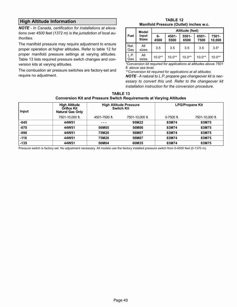
Page 43
High Altitude Information
NOTE − In Canada, certification for installations at eleva-
tions over 4500 feet (1372 m) is the jurisdiction of local au-
thorities.
The manifold pressure may require adjustment to ensure
proper operation at higher altitudes. Refer to table 12 for
proper manifold pressure settings at varying altitudes.
Table 13 lists required pressure switch changes and con-
version kits at varying altitudes.
The combustion air pressure switches are factory−set and
require no adjustment.
TABLE 12Manifold Pressure (Outlet) inches w.c.
FuelModelInputSizes
Altitude (feet)
0−4500
4501−5500
5501−6500
6501−7500
7501−10,000
Nat.Gas
Allsizes
3.5 3.5 3.5 3.5 3.5*
L.P.Gas
Allsizes
10.0** 10.0** 10.0** 10.0** 10.0**
*Conversion kit required for applications at altitudes above 7501ft. above sea level.**Conversion kit required for applications at all altitudes.
NOTE − A natural to L.P. propane gas changeover kit is nec-
essary to convert this unit. Refer to the changeover kit
installation instruction for the conversion procedure.
TABLE 13Conversion Kit and Pressure Switch Requirements at Varying Altitudes
Input
High AltitudeOrifice Kit
Natural Gas Only
High Altitude PressureSwitch Kit
LPG/Propane Kit
7501−10,000 ft. 4501−7500 ft. 7501−10,000 ft. 0−7500 ft. 7501−10,000 ft.
−045 44W51 − − − 95M22 83M74 83M75
−070 44W51 56M05 56M06 83M74 83M75
−090 44W51 75M20 56M07 83M74 83M75
−110 44W51 75M20 56M07 83M74 83M75
−135 44W51 56M04 60M35 83M74 83M75
Pressure switch is factory set. No adjustment necessary. All models use the factory installed pressure switch from 0−4500 feet (0−1370 m).
Page 44
Testing for Proper Venting and Sufficient Combustion Air for Non−Direct Vent Applications
WARNINGCARBON MONOXIDE POISONING HAZARD!
Failure to follow the steps outlined below for eachappliance connected to the venting system beingplaced into operation could result in carbon monox-ide poisoning or death.The following steps shall be followed for each ap-pliance connected to the venting system beingplaced into operation, while all other appliances con-nected to the venting system are not in operation.
After the G51MP gas furnace has been started, the follow-
ing test should be conducted to ensure proper venting and
sufficient combustion air has been provided to the G51MP,
as well as to other gas-fired appliances which are separate-
ly vented.
If a G51MP furnace replaces a Category I furnace which
was commonly vented with another gas appliance, the size
of the existing vent pipe for that gas appliance must be
checked. Without the heat of the original furnace flue prod-
ucts, the existing vent pipe is probably oversized for the
single water heater or other appliance. The vent should be
checked for proper draw with the remaining appliance.
The test should be conducted while all appliances (both in
operation and those not in operation) are connected to the
venting system being tested. If the venting system has
been installed improperly, or if provisions have not been
made for sufficient amounts of combustion air, corrections
must be made as outlined in the previous section.
1 − Seal any unused openings in the venting system.
2 − Visually inspect the venting system for proper size and
horizontal pitch. Determine there is no blockage or re-striction, leakage, corrosion, or other deficiencieswhich could cause an unsafe condition.
3 − To the extent that it is practical, close all building doorsand windows and all doors between the space in whichthe appliances connected to the venting system are lo-cated and other spaces of the building.
4 − Close fireplace dampers.
5 − Turn on clothes dryers and any appliances not con-nected to the venting system. Turn on any exhaustfans, such as range hoods and bathroom exhausts, sothey will operate at maximum speed. Do not operate asummer exhaust fan.
6 − Follow the lighting instruction to place the appliancebeing inspected into operation. Adjust thermostat soappliance will operate continuously.
7 − Use the flame of match or candle to test for spillage offlue gases at the draft hood relief opening after 5 min-utes of main burner operation.
8 − If improper venting is observed during any of theabove tests, the venting system must be corrected orsufficient combustion/make-up air must be provided.The venting system should be re-sized to approachthe minimum size as determined by using the ap-propriate tables in appendix G in the current standardsof the National Fuel Gas Code ANSI−Z223.1/NPFA 54in the U.S.A., and the appropriate Natural Gas andPropane appliances venting sizing tables in the cur-rent standard of the CSA−B149 Natural Gas and Pro-pane Installation Codes in Canada.
9 − After determining that each appliance remainingconnected to the common venting system properlyvents when tested as indicated in step 3, returndoors, windows, exhaust fans, fireplace dampersand any other gas-burning appliance to their previouscondition of use.
Page 45
Other Unit Adjustments
Primary and Secondary Limits
The primary limit is located on the heating compartment
vestibule panel. The secondary limits are located in the
blower compartment, attached to the back side of the blow-
er. These limits are factory set and require no adjustment.
Flame Rollout Switches (Two)
These manually reset switches are located on the burner
box. If tripped, check for adequate combustion air before
resetting.
Pressure Switches (Two)
The pressure switches are located in the heating compart-
ment on the combustion air inducer. These switches check
for proper combustion air inducer operation before allow-
ing ignition trial. The switches are factory−set and require
no adjustment.
Temperature Rise
After the furnace has been started and supply and return air
temperatures have been allowed to stabilize, check the
temperature rise. If necessary, adjust the blower speed to
maintain the temperature rise within the range shown on
the unit nameplate. Increase the blower speed to decrease
the temperature. Decrease the blower speed to increase
the temperature rise. Failure to adjust the temperature rise
may cause erratic limit operation.
Fan Control
Heating Mode −− The fan on delay of 45 seconds is notadjustable. The fan off delay (amount of time that theblower operates after the heat demand has been satis-fied) may be adjusted by setting S1 switches 1 and 2 lo-cated on the SureLight® control. The unit is shipped witha factory fan off setting of 90 seconds. The fan off delayaffects comfort and is adjustable to satisfy individual ap-plications. Adjust the fan off delay to achieve a supply airtemperature between 90° and 110°F at the exact mo-ment that the blower is de−energized. Longer off delaysettings provide lower return air temperatures; shortersettings provide higher return air temperatures. See fig-ure 55.Cooling Mode −− The cooling mode fan off delay (amount
of time that the blower operates after the cooling demand
has been satisfied) may be adjusted by setting S1 switch
3 located on the SureLight® control. In the off position,
the cooling fan off delay is 2 seconds. In the on position,
the cooling fan off delay is 45 seconds. See figure 55.
Thermostat Heat Anticipation
Set the heat anticipator setting (if adjustable) according to
the amp draw listed on the wiring diagram that is attached
to the unit.
Electrical
1 − Check all wiring for loose connections.
2 − Check for the correct voltage at the furnace (furnaceoperating).
3 − Check amp-draw on the blower motor.Motor Nameplate__________Actual__________
NOTE − Do not secure the electrical conduit directly to theair ducts or structure.
Blower Speeds
NOTE − CFM readings are taken external to unit with a dryevaporator coil and without accessories.
Turn off electrical power to furnace.
Remove blower access panel.
Disconnect existing speed tap at control board speedterminal.
NOTE − Termination of any unused motor leads must beinsulated.
Refer to blower speed selection chart on unit wiring dia-gram for desired heating or cooling speed. See blowerperformance data beginning on Page 46.
Connect selected speed tap at control board speedterminal.
Resecure blower access panel.
Turn on electrical power to furnace.
Electronic Ignition
The SureLight® integrated control has an added feature ofan internal Watchguard control. The feature serves as anautomatic reset device for ignition control lockout caused byignition failure. This type of lockout is usually due to low gasline pressure. After one hour of continuous thermostat de-mand for heat, the Watchguard will break and remake ther-mostat demand to the furnace and automatically reset thecontrol to begin the ignition sequence.
Exhaust and Air Intake Pipe
1 − Check exhaust and air intake connections for tightnessand to make sure there is no blockage.
2 − Are pressure switches closed? Obstructed exhaustpipe will cause unit to shut off at pressure switches.Check termination for blockages.
3 − Reset manual flame rollout switches on burner boxcover.
Failure To Operate
If the unit fails to operate, check the following:
1 − Is the thermostat calling for heat?
2 − Are access panels securely in place?
3 − Is the main disconnect switch closed?
4 − Is there a blown fuse?
5 − Is the filter dirty or plugged? Dirty or plugged filters willcause the limit control to shut the unit off.
6 − Is gas turned on at the meter?
7 − Is the manual main shut-off valve open?
8 − Is the internal manual shut-off valve open?
9 − Is the unit ignition system in lock out? If the unit locks outagain, inspect the unit for blockages.

Page 46
Blower Motor Performance
G51MP−24B−045 PERFORMANCE (Less Filter)
ExternalStatic
Pressurein. w.g.
Air Volume / Watts at Different Blower Speeds
HighMedium−
HighMedium−
Low Low
cfm Watts cfm Watts cfm Watts cfm Watts
0.00 1125 425 900 360 745 295 690 265
0.10 1115 410 905 350 760 285 695 260
0.20 1090 395 895 335 755 280 685 255
0.30 1060 380 880 325 740 270 675 250
0.40 1020 365 860 315 720 260 665 240
0.50 970 345 835 300 700 255 640 230
0.60 920 335 795 290 665 240 600 220
0.70 860 315 730 270 620 230 565 215
0.80 760 295 665 250 560 215 510 200
0.90 675 275 585 230 495 200 465 175
G51MP−36B−045 PERFORMANCE (Less Filter)
ExternalStatic
Pressurein. w.g.
Air Volume / Watts at Different Blower Speeds
HighMedium−
HighMedium−
LowLow
cfm Watts cfm Watts cfm Watts cfm Watts
0.00 1555 630 1410 585 1190 520 1030 435
0.10 1515 605 1385 555 1190 485 1020 415
0.20 1470 580 1345 520 1170 455 1010 400
0.30 1410 555 1310 495 1155 440 1000 385
0.40 1350 535 1250 465 1120 410 980 360
0.50 1290 505 1205 450 1080 390 950 345
0.60 1220 485 1145 420 1020 365 905 320
0.70 1145 460 1080 400 975 345 860 300
0.80 1050 425 985 365 870 320 785 285
0.90 945 410 900 345 825 305 730 270
NOTES − Air volume based on bottom return air. Actual air volume may vary on side return air applications.
G51MP−36B−070 PERFORMANCE (Less Filter)
ExternalStatic
Pressurein. w.g.
Air Volume / Watts at Different Blower Speeds
HighMedium−
HighMedium−
LowLow
cfm Watts cfm Watts cfm Watts cfm Watts
0.00 1640 660 1415 575 1160 485 1005 410
0.10 1600 635 1395 550 1160 460 1000 385
0.20 1540 605 1370 525 1160 445 995 375
0.30 1495 580 1345 505 1145 425 990 365
0.40 1420 545 1275 480 1125 395 965 345
0.50 1360 525 1245 450 1080 375 945 325
0.60 1275 490 1165 410 1025 350 900 305
0.70 1170 465 1085 385 965 335 860 295
0.80 1080 440 1010 360 865 310 775 270
0.90 945 400 840 320 765 275 710 245
G51MP−36C−090 PERFORMANCE (Less Filter)
ExternalStatic
Pressurein. w.g.
Air Volume / Watts at Different Blower Speeds
HighMedium−
HighMedium−
LowLow
cfm Watts cfm Watts cfm Watts cfm Watts
0.00 1630 745 1360 635 1125 540 975 440
0.10 1620 715 1365 610 1160 515 1000 430
0.20 1590 680 1365 580 1160 495 990 405
0.30 1550 655 1355 565 1170 475 985 395
0.40 1520 630 1330 545 1160 460 980 380
0.50 1465 605 1300 515 1140 440 960 360
0.60 1415 570 1250 490 1095 420 940 350
0.70 1350 545 1215 470 1065 400 905 335
0.80 1260 510 1140 440 1005 375 850 310
0.90 1165 475 1035 395 900 335 730 285
NOTES − Air volume based on bottom return air. Actual air volume may vary on side return air applications.
ExternalStatic
Pressurein. w.g.
G51MP−48C−090 PERFORMANCE (Less Filter)
Air Volume / Watts at Different Blower Speeds
HighMedium−
HighMedium−
LowLow
cfm Watts cfm Watts cfm Watts cfm Watts
0.00 2180 930 1835 790 1520 630 1280 510
0.10 2135 885 1825 750 1510 610 1275 495
0.20 2085 840 1810 720 1505 580 1270 475
0.30 2030 800 1775 685 1500 565 1265 460
0.40 1940 760 1735 650 1480 535 1250 440
0.50 1865 725 1660 600 1430 505 1215 425
0.60 1740 670 1590 575 1380 475 1175 410
0.70 1645 640 1475 520 1290 450 1105 375
0.80 1540 600 1340 465 1175 405 1020 355
0.90 1335 540 1170 440 1070 375 950 330
G51MP−48C−110 PERFORMANCE (Less Filter)
ExternalStatic
Pressurein. w.g.
Air Volume / Watts at Different Blower Speeds
HighMedium−
HighMedium−
LowLow
cfm Watts cfm Watts cfm Watts cfm Watts
0.00 2160 880 1880 755 1490 602 1235 485
0.10 2100 850 1855 730 1480 585 1230 475
0.20 2035 805 1815 690 1475 560 1225 460
0.30 1965 750 1755 650 1475 545 1220 445
0.40 1885 725 1715 625 1465 510 1215 430
0.50 1780 680 1630 580 1420 490 1150 400
0.60 1690 660 1550 550 1360 460 1110 380
0.70 1575 620 1410 505 1210 405 1035 350
0.80 1375 550 1230 450 1125 380 970 325
0.90 1225 520 1120 415 1050 365 885 310
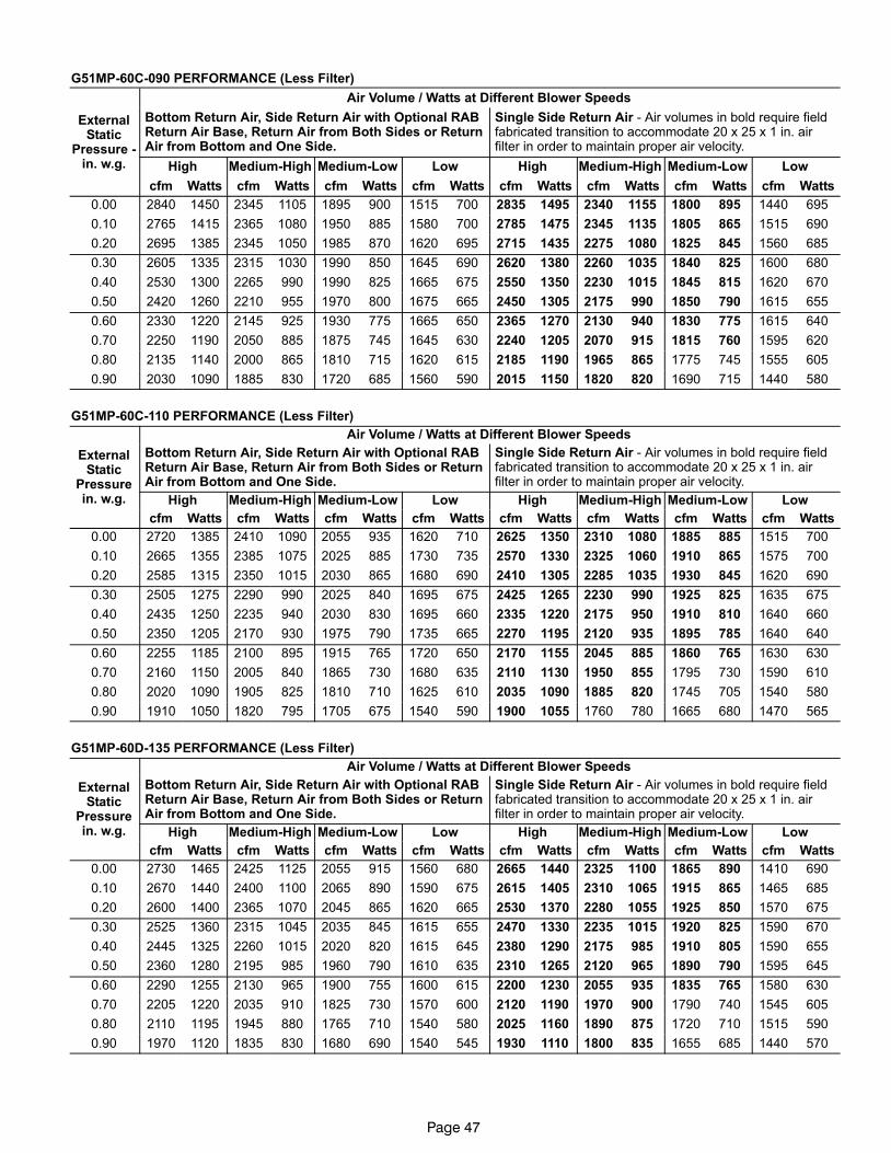
Page 47
G51MP−60C−090 PERFORMANCE (Less Filter)
ExternalStatic
Pressure −in. w.g.
Air Volume / Watts at Different Blower Speeds
Bottom Return Air, Side Return Air with Optional RABReturn Air Base, Return Air from Both Sides or ReturnAir from Bottom and One Side.
Single Side Return Air − Air volumes in bold require fieldfabricated transition to accommodate 20 x 25 x 1 in. airfilter in order to maintain proper air velocity.
High Medium−High Medium−Low Low High Medium−High Medium−Low Low
cfm Watts cfm Watts cfm Watts cfm Watts cfm Watts cfm Watts cfm Watts cfm Watts
0.00 2840 1450 2345 1105 1895 900 1515 700 2835 1495 2340 1155 1800 895 1440 695
0.10 2765 1415 2365 1080 1950 885 1580 700 2785 1475 2345 1135 1805 865 1515 690
0.20 2695 1385 2345 1050 1985 870 1620 695 2715 1435 2275 1080 1825 845 1560 685
0.30 2605 1335 2315 1030 1990 850 1645 690 2620 1380 2260 1035 1840 825 1600 680
0.40 2530 1300 2265 990 1990 825 1665 675 2550 1350 2230 1015 1845 815 1620 670
0.50 2420 1260 2210 955 1970 800 1675 665 2450 1305 2175 990 1850 790 1615 655
0.60 2330 1220 2145 925 1930 775 1665 650 2365 1270 2130 940 1830 775 1615 640
0.70 2250 1190 2050 885 1875 745 1645 630 2240 1205 2070 915 1815 760 1595 620
0.80 2135 1140 2000 865 1810 715 1620 615 2185 1190 1965 865 1775 745 1555 605
0.90 2030 1090 1885 830 1720 685 1560 590 2015 1150 1820 820 1690 715 1440 580
G51MP−60C−110 PERFORMANCE (Less Filter)
ExternalStatic
Pressurein. w.g.
Air Volume / Watts at Different Blower Speeds
Bottom Return Air, Side Return Air with Optional RABReturn Air Base, Return Air from Both Sides or ReturnAir from Bottom and One Side.
Single Side Return Air − Air volumes in bold require fieldfabricated transition to accommodate 20 x 25 x 1 in. airfilter in order to maintain proper air velocity.
High Medium−High Medium−Low Low High Medium−High Medium−Low Low
cfm Watts cfm Watts cfm Watts cfm Watts cfm Watts cfm Watts cfm Watts cfm Watts
0.00 2720 1385 2410 1090 2055 935 1620 710 2625 1350 2310 1080 1885 885 1515 700
0.10 2665 1355 2385 1075 2025 885 1730 735 2570 1330 2325 1060 1910 865 1575 700
0.20 2585 1315 2350 1015 2030 865 1680 690 2410 1305 2285 1035 1930 845 1620 690
0.30 2505 1275 2290 990 2025 840 1695 675 2425 1265 2230 990 1925 825 1635 675
0.40 2435 1250 2235 940 2030 830 1695 660 2335 1220 2175 950 1910 810 1640 660
0.50 2350 1205 2170 930 1975 790 1735 665 2270 1195 2120 935 1895 785 1640 640
0.60 2255 1185 2100 895 1915 765 1720 650 2170 1155 2045 885 1860 765 1630 630
0.70 2160 1150 2005 840 1865 730 1680 635 2110 1130 1950 855 1795 730 1590 610
0.80 2020 1090 1905 825 1810 710 1625 610 2035 1090 1885 820 1745 705 1540 580
0.90 1910 1050 1820 795 1705 675 1540 590 1900 1055 1760 780 1665 680 1470 565
G51MP−60D−135 PERFORMANCE (Less Filter)
ExternalStatic
Pressurein. w.g.
Air Volume / Watts at Different Blower Speeds
Bottom Return Air, Side Return Air with Optional RABReturn Air Base, Return Air from Both Sides or ReturnAir from Bottom and One Side.
Single Side Return Air − Air volumes in bold require fieldfabricated transition to accommodate 20 x 25 x 1 in. airfilter in order to maintain proper air velocity.
High Medium−High Medium−Low Low High Medium−High Medium−Low Low
cfm Watts cfm Watts cfm Watts cfm Watts cfm Watts cfm Watts cfm Watts cfm Watts
0.00 2730 1465 2425 1125 2055 915 1560 680 2665 1440 2325 1100 1865 890 1410 690
0.10 2670 1440 2400 1100 2065 890 1590 675 2615 1405 2310 1065 1915 865 1465 685
0.20 2600 1400 2365 1070 2045 865 1620 665 2530 1370 2280 1055 1925 850 1570 675
0.30 2525 1360 2315 1045 2035 845 1615 655 2470 1330 2235 1015 1920 825 1590 670
0.40 2445 1325 2260 1015 2020 820 1615 645 2380 1290 2175 985 1910 805 1590 655
0.50 2360 1280 2195 985 1960 790 1610 635 2310 1265 2120 965 1890 790 1595 645
0.60 2290 1255 2130 965 1900 755 1600 615 2200 1230 2055 935 1835 765 1580 630
0.70 2205 1220 2035 910 1825 730 1570 600 2120 1190 1970 900 1790 740 1545 605
0.80 2110 1195 1945 880 1765 710 1540 580 2025 1160 1890 875 1720 710 1515 590
0.90 1970 1120 1835 830 1680 690 1540 545 1930 1110 1800 835 1655 685 1440 570
Page 48
Service
WARNINGELECTRICAL SHOCK, FIRE,OR EXPLOSION HAZARD.
Failure to follow safety warnings exactly could resultin dangerous operation, serious injury, death orproperty damage.Improper servicing could result in dangerous opera-tion, serious injury, death, or property damage.Before servicing, disconnect all electrical power tofurnace.When servicing controls, label all wires prior to dis-connecting. Take care to reconnect wires correctly.Verify proper operation after servicing.
At the beginning of each heating season, system should be
checked as follows by a qualified service technician:
Blower
Check the blower wheel for debris and clean if necessary.
The blower motors are prelubricated for extended bearing
life. No further lubrication is needed.
WARNINGThe blower access panel must be securely in placewhen the blower and burners are operating. Gasfumes, which could contain carbon monoxide, canbe drawn into living space resulting in personal inju-ry or death.
Filters
All G51MP filters are installed external to the unit. Filters
should be inspected monthly. Clean or replace the filters
when necessary to ensure proper furnace operation.
Table 3 lists recommended filter sizes.
Exhaust and air intake pipes
Check the exhaust and air intake pipes and all connections
for tightness and to make sure there is no blockage.
NOTE − After any heavy snow, ice or frozen fog event the
furnace vent pipes may become restricted. Always check
the vent system and remove any snow or ice that may be
obstructing the plastic intake or exhaust pipes.
Electrical
1 − Check all wiring for loose connections.
2 − Check for the correct voltage at the furnace (furnace
operating).
3 − Check amp−draw on the blower motor.Motor Nameplate__________Actual__________
Winterizing and Condensate Trap Care 1 − Turn off power to the unit.
2 − Have a shallow pan ready to empty condensate water.
3 − Remove the drain plug from the condensate trap and
empty water. Inspect the trap then reinstall the drain
plug.
Cleaning Heat ExchangerIf cleaning the heat exchanger becomes necessary, follow
the below procedures and refer to figure 1 when disassem-
bling unit. Use papers or protective covering in front of fur-
nace while removing heat exchanger assembly.
1 − Turn off electrical and gas supplies to the furnace.
2 − Remove the upper and lower furnace access panels.
3 − Mark all gas valve wires and disconnect them from
valve.
4 − Remove gas supply line connected to gas valve. Re-
move gas valve/manifold assembly.
5 − Remove sensor wire from sensor. Disconnect 2-pin or
3−pin plug from the ignitor.
6 − Disconnect wires from flame roll−out switches.
7 − Remove burner box cover and remove four burner box
screws at the vestibule panel and remove burner box.
Set burner box assembly aside.
NOTE − If necessary, clean burners at this time. Follow
procedures outlined in Burner Cleaning section.
8 − Loosen three clamps and remove flexible exhaust tee.
9 − Remove 3/8 inch rubber cap from condensate drain
plug and drain. Replace cap after draining.
10 − Disconnect condensate drain line from the conden-
sate trap. Remove condensate trap (it may be neces-
sary to cut drain pipe). Remove screws that secure
condensate collars to either side of the furnace and re-
move collars. Remove drain tubes from cold end
header collector box.
11 − Disconnect condensate drain tubing from flue collar.
Remove screws that secure both flue collars into
place. Remove flue collars. It may be necessary to cut
the exiting exhaust pipe for removal of the fittings.
12 − Disconnect the 2-pin plug from the combustion air in-
ducer. Disconnect the two wires to the secondary limit,
if applicable. Remove four screws which secure com-
bustion air inducer to collector box Remove combus-
tion air inducer assembly. Remove ground wire from
vest panel.
13 − Mark and disconnect all combustion air pressure tub-
ing from cold end header collector box.
14 − Mark and remove wires from pressure switches. Re-
move pressure switches. Keep tubing attached to
pressure switches.
15 − Remove electrical junction box from the side of the fur-
nace.
16 − Mark and disconnect any remaining wiring to heating
compartment components. Disengage strain relief
bushing and pull wiring and bushing through the hole in
the blower deck.
Page 49
17 − Remove the primary limit from the vestibule panel.
18 − Remove two screws from the front cabinet flange at
the blower deck. Spread cabinet sides slightly to allow
clearance for removal of heat exchanger.
19 − Remove screws along vestibule sides and bottom
which secure vestibule panel and heat exchanger as-
sembly to cabinet. Remove two screws from blower
rail which secure bottom heat exchanger flange. Re-
move heat exchanger from furnace cabinet.
20 − Back wash heat exchanger with soapy water solution
or steam. If steam is used it must be below 275°F
(135°C) .
21 − Thoroughly rinse and drain the heat exchanger. Soap
solutions can be corrosive. Take care to rinse entire
assembly.
22 − Reinstall heat exchanger into cabinet making sure that
the clamshells of the heat exchanger assembly are
resting on the support located at the rear of the cabi-
net. Remove the indoor blower to view this area
through the blower opening.
23 − Re-secure the supporting screws along the vestibule
sides and bottom to the cabinet.
24 − Reinstall cabinet screws on front flange at blower
deck.
25 − Reinstall the primary limit on the vestibule panel.
26 − Route heating component wiring through hole in blow-
er deck and reinsert strain relief bushing.
27 − Reinstall pressure switches and reconnect pressure
switch wiring.
28 − Carefully connect combustion air pressure switch
hosing from pressure switches to proper stubs on
cold end header collector box.
29 − Reinstall condensate collars on each side of the fur-
nace. Reconnect drain tubing to collector box.
30 − Reinstall condensate trap on same side as exhaust
pipe. Reconnect condensate drain line to the conden-
sate trap.
31 − Reinstall electrical junction box.
32 − Reinstall the combustion air inducer. Reconnect the
2−pin or 3−pin plug to the wire harness. Reconnect the
two wires to the secondary limit, if applicable.
33 − Use securing screws to reinstall flue collars to either
side of the furnace. Reconnect exhaust piping and ex-
haust drain tubing.
34 − Replace flexible exhaust tee on combustion air induc-
er and flue collars. Secure using three existing hose
clamps.
35 − Reinstall burner box assembly in vestibule area.
36 − Reconnect flame roll−out switch wires.
37 − Reconnect sensor wire and reconnect 2−pin plug from
ignitor.
38 − Secure burner box assembly to vestibule panel using
four existing screws. Make sure burners line up in
center of burner ports.
39 − Reinstall gas valve manifold assembly. Reconnect
gas supply line to gas valve.
40 − Reinstall burner box cover.
41 − Reconnect wires to gas valve.
42 − Replace the blower compartment access panel.
43 − Refer to instruction on verifying gas and electrical con-
nections when re−establishing supplies.
44 − Follow lighting instructions to light and operate fur-
nace for 5 minutes to ensure that heat exchanger is
clean and dry and that furnace is operating properly.
45 − Replace heating compartment access panel.
Cleaning the Burner Assembly
1 − Turn off electrical and gas power supplies to furnace.
Remove upper and lower furnace access panels.
2 − Mark all gas valve wires and disconnect them from the
valve.
3 − Disconnect the gas supply line from the gas valve. Re-
move gas valve/manifold assembly.
4 − Mark and disconnect sensor wire from the sensor. Dis-
connect 2-pin plug from the ignitor at the burner box.
5 − Remove burner box cover and remove four screws
which secure burner box assembly to vest panel. Re-
move burner box from the unit.
6 − Use the soft brush attachment on a vacuum cleaner to
gently clean the face of the burners. Visually inspect
the inside of the burners and crossovers for any block-
age caused by foreign matter. Remove any blockage.
7 − Reconnect the sensor wire and reconnect the 2−pin
plug to the ignitor wiring harness.
8 − Reinstall the burner box assembly using the existing
four screws. Make sure that the burners line up in the
center of the burner ports.
9 − Reinstall the gas valve manifold assembly. Reconnect
the gas supply line to the gas valve. Reinstall the burn-
er box cover.
10 − Reconnect the gas valve wires to the gas valve.
11 − Replace the blower compartment access panel.
12 − Refer to instruction on verifying gas and electrical con-
nections when re−establishing supplies.
13 − Follow lighting instructions to light and operate fur-
nace for 5 minutes to ensure that heat exchanger is
clean and dry and that furnace is operating properly.
14 − Replace heating compartment access panel.
Page 50
Planned Service
A service technician should check the following items dur-
ing an annual inspection. Power to the unit must be shut off
for safety.
Fresh air grilles and louvers (on the unit and in the room
where the furnace is installed) − Must be open and unob-
structed to provide combustion air.
Burners − Must be inspected for rust, dirt, or signs of water.
Vent pipe − Must be inspected for signs of water, damaged,
cracked or sagging pipe, or disconnected joints.
Unit appearance − Must be inspected for rust, dirt, signs
of water, burnt or damaged wires, or components.
Blower access door − Must be properly in place and pro-
vide a seal between the return air and the room where the
furnace is installed.
Return air duct − Must be properly attached and provide
an air seal to the unit.
Operating performance − Unit must be observed during
operation to monitor proper performance of the unit and the
vent system.
Combustion gases − Flue products must be analyzed and
compared to the unit specifications.
Problems detected during the inspection may make it nec-
essary to temporarily shut down the furnace until the items
can be repaired or replaced.
Instruct the homeowners to pay attention to their
furnace. Situations can arise between annual furnace in-
spections that may result in unsafe operation. For instance,
items innocently stored next to the furnace may obstruct
the combustion air supply. This could cause incomplete
combustion and the production of carbon monoxide gas.
Repair Parts List
The following repair parts are available through Lennox dealers. When ordering parts, include the complete furnace model
number listed on the CSA nameplate −− Example: G51MP−24B−045−1. All service must be performed by a licensed pro-
fessional installer (or equivalent), service agency, or gas supplier.
Cabinet Parts
Upper access panel
Blower access panel
Top cap
Control Panel Parts
TransformerSureLight® integrated control board
Door interlock switchCircuit breaker
Blower Parts
Blower wheelMotor
Motor mounting frameMotor capacitor
Blower housing cutoff plate
Heating Parts
Flame SensorHeat exchanger assembly
Gas manifold
Combustion air inducerGas valve
Main burner clusterMain burner orifices
Pressure switches
IgnitorPrimary limit control
Secondary limit controlFlame rollout switches
Combustion air inducer auxiliary limit

Page 51
SureLight® Troubleshooting: Heating Sequence of Operation
SURELIGHT CONTROLHEATING SEQUENCE OF OPERATION
NORMAL HEATING MODE ABNORMAL HEATING MODE
CONTROL SELF−CHECK OKAY?
BURNER OFF?(CONTINUOUS FLAME CHECK)
NORMAL OPERATION:DS1 −− SLOW FLASHDS2 −− SLOW FLASH
YES
YES
YES
GAS VALVE OFF. COMBUSTION AIR INDUCER OFF.INDOOR BLOWER DELAY OFF.
DS1 ONDS2 ON
(RESET CONTROL BY TURNING MAIN POWER OFF.)
POLARITY REVERSED.DS1 −− FAST FLASHDS2 −− SLOW FLASH
POWER ON
IS POLARITY REVERSED?
ROLLOUT SWITCHES CLOSED?
THERMOSTAT CALLS FOR HEAT:DS1 −− FAST FLASHDS2 −− FAST FLASH
ARE COMBUSTION AIRPRESSURE SWITCHES OPEN?
GAS VALVE OFF. COMBUSTION AIR INDUCER OFF.INDOOR BLOWER OFF WITH DELAY.
DS1 −− ON. DS2 −− SLOW FLASH.SEQUENCE HOLDS UNTIL ROLLOUT SWITCH CLOSES.
GAS VALVE OFF. COMBUSTION AIR INDUCER ON.INDOOR BLOWER ON HEATING SPEED.
DS1 −− SLOW FLASHDS2 −− OFF
GAS VALVE OFF.COMBUSTION AIR INDUCER OFF.
INDOOR BLOWER OFF WITH DELAY.DS1 OFF
DS2 SLOW FLASH(Sequence holds until pressure switchcloses or thermostat resets control.)
NO
NOYES
NO
IS VOLTAGEABOVE 75 VOLTS?
DS1 AND DS2 ALTERNATING FASTFLASH. SIGNAL HOLDS UNTIL VOLTAGE
RISES ABOVE 75 VOLTS.
NO
NO
NO
IS COMBUSTION AIR INDUCER ENERGIZED?(HUM TERMINALS ARE ENERGIZED WITH CAI)
HAVE COMBUSTION AIR PRESSURESWITCHES CLOSED IN 2.5 MINUTES?
YES
YESPRESSURE SWITCHES IN WATCHGUARD MODE.
GAS VALVE OFF. COMBUSTION AIR INDUCER OFF.INDOOR BLOWER OFF WITH DELAY.
DS1 −− OFF. DS2 −− SLOW FLASH.IS 5-MINUTE RESET PERIOD COMPLETE?
NO
YES
CONTINUED NEXT PAGE
YES
GAS VALVE OFF. COMBUSTION AIR INDUCER ON.INDOOR BLOWER ON.
DS1 ALTERNATING FAST FLASHDS2 ALTERNATING FAST FLASH
CHECK FOR BROKEN IGNITOR OR OPEN IGNITOR CIRCUIT
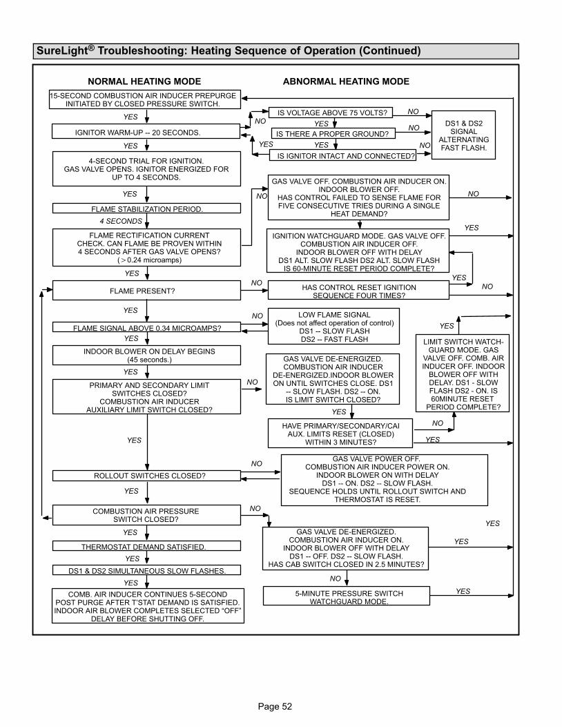
Page 52
SureLight® Troubleshooting: Heating Sequence of Operation (Continued)
LIMIT SWITCH WATCH-GUARD MODE. GAS
VALVE OFF. COMB. AIRINDUCER OFF. INDOOR
BLOWER OFF WITHDELAY. DS1 − SLOWFLASH DS2 − ON. IS60MINUTE RESET
PERIOD COMPLETE?
NORMAL HEATING MODE ABNORMAL HEATING MODE
FLAME RECTIFICATION CURRENTCHECK. CAN FLAME BE PROVEN WITHIN4 SECONDS AFTER GAS VALVE OPENS?
(�0.24 microamps)
FLAME PRESENT?
INDOOR BLOWER ON DELAY BEGINS(45 seconds.)
PRIMARY AND SECONDARY LIMITSWITCHES CLOSED?
COMBUSTION AIR INDUCERAUXILIARY LIMIT SWITCH CLOSED?
COMBUSTION AIR PRESSURESWITCH CLOSED?
LOW FLAME SIGNAL(Does not affect operation of control)
DS1 −− SLOW FLASHDS2 −− FAST FLASH
GAS VALVE DE−ENERGIZED.COMBUSTION AIR INDUCER
DE−ENERGIZED.INDOOR BLOWERON UNTIL SWITCHES CLOSE. DS1
−− SLOW FLASH. DS2 −− ON.IS LIMIT SWITCH CLOSED?
GAS VALVE DE−ENERGIZED.COMBUSTION AIR INDUCER ON.
INDOOR BLOWER OFF WITH DELAYDS1 −− OFF. DS2 −− SLOW FLASH.
HAS CAB SWITCH CLOSED IN 2.5 MINUTES?
15-SECOND COMBUSTION AIR INDUCER PREPURGEINITIATED BY CLOSED PRESSURE SWITCH.
YES
IGNITOR WARM-UP −− 20 SECONDS.
YES
4-SECOND TRIAL FOR IGNITION.GAS VALVE OPENS. IGNITOR ENERGIZED FOR
UP TO 4 SECONDS.
YES
FLAME STABILIZATION PERIOD.
GAS VALVE OFF. COMBUSTION AIR INDUCER ON.INDOOR BLOWER OFF.
HAS CONTROL FAILED TO SENSE FLAME FORFIVE CONSECUTIVE TRIES DURING A SINGLE
HEAT DEMAND?
IGNITION WATCHGUARD MODE. GAS VALVE OFF.COMBUSTION AIR INDUCER OFF.
INDOOR BLOWER OFF WITH DELAYDS1 ALT. SLOW FLASH DS2 ALT. SLOW FLASH
IS 60-MINUTE RESET PERIOD COMPLETE?
YES
4 SECONDS
YES
HAS CONTROL RESET IGNITIONSEQUENCE FOUR TIMES?
FLAME SIGNAL ABOVE 0.34 MICROAMPS?
YES
YES
HAVE PRIMARY/SECONDARY/CAIAUX. LIMITS RESET (CLOSED)
WITHIN 3 MINUTES?
YES
ROLLOUT SWITCHES CLOSED?
GAS VALVE POWER OFF. COMBUSTION AIR INDUCER POWER ON.
INDOOR BLOWER ON WITH DELAYDS1 −− ON. DS2 −− SLOW FLASH.
SEQUENCE HOLDS UNTIL ROLLOUT SWITCH ANDTHERMOSTAT IS RESET.
YES
THERMOSTAT DEMAND SATISFIED.
DS1 & DS2 SIMULTANEOUS SLOW FLASHES.
COMB. AIR INDUCER CONTINUES 5-SECONDPOST PURGE AFTER T’STAT DEMAND IS SATISFIED.INDOOR AIR BLOWER COMPLETES SELECTED �OFF"
DELAY BEFORE SHUTTING OFF.
YES
NO
5-MINUTE PRESSURE SWITCHWATCHGUARD MODE.
YES
IS THERE A PROPER GROUND?
IS VOLTAGE ABOVE 75 VOLTS?
IS IGNITOR INTACT AND CONNECTED?
DS1 & DS2SIGNAL
ALTERNATINGFAST FLASH.
NO YES
YESYES
YES
YES
NO
NO
NO
NO
NO
NO
NO
NO
YES
YES
NO
NO
NO
NO
YES
YES
YES
YES
YES
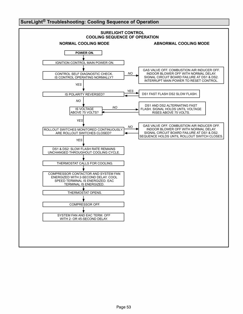
Page 53
SureLight® Troubleshooting: Cooling Sequence of Operation
SURELIGHT CONTROLCOOLING SEQUENCE OF OPERATION
NORMAL COOLING MODE ABNORMAL COOLING MODE
IGNITION CONTROL MAIN POWER ON.
CONTROL SELF DIAGNOSTIC CHECK.IS CONTROL OPERATING NORMALLY?
YES
POWER ON.
GAS VALVE OFF. COMBUSTION AIR INDUCER OFF.INDOOR BLOWER OFF WITH NORMAL DELAY.
SIGNAL CIRCUIT BOARD FAILURE AT DS1 & DS2.INTERRUPT MAIN POWER TO RESET CONTROL.
YESIS POLARITY REVERSED?
ROLLOUT SWITCHES MONITORED CONTINUOUSLY.ARE ROLLOUT SWITCHES CLOSED?
DS1 & DS2: SLOW FLASH RATE REMAINSUNCHANGED THROUGHOUT COOLING CYCLE.
THERMOSTAT CALLS FOR COOLING.
COMPRESSOR CONTACTOR AND SYSTEM FANENERGIZED WITH 2-SECOND DELAY. COOL
SPEED TERMINAL IS ENERGIZED. EACTERMINAL IS ENERGIZED.
COMPRESSOR OFF.
THERMOSTAT OPENS.
SYSTEM FAN AND EAC TERM. OFFWITH 2− OR 45-SECOND DELAY.
NO
YES
NO
GAS VALVE OFF. COMBUSTION AIR INDUCER OFF.INDOOR BLOWER OFF WITH NORMAL DELAY.
SIGNAL CIRCUIT BOARD FAILURE AT DS1 & DS2.SEQUENCE HOLDS UNTIL ROLLOUT SWITCH CLOSES.
NO
IS VOLTAGEABOVE 75 VOLTS?
NODS1 AND DS2 ALTERNATING FAST
FLASH. SIGNAL HOLDS UNTIL VOLTAGERISES ABOVE 75 VOLTS.
DS1 FAST FLASH DS2 SLOW FLASH.
YES

Page 54
SureLight® Troubleshooting: Continuous Fan Sequence of Operation
SURELIGHT CONTROLCONTINUOUS FAN SEQUENCE OF OPERATION
DS1 & DS2: SLOW FLASH RATE REMAINSUNCHANGED THROUGHOUT SEQUENCE.
MANUAL FAN SELECTION MADE AT THERMOSTAT.CONTROL (G) ENERGIZES INDOOR BLOWER AT
FAN SPEED. EAC TERM. IS ENERGIZED.
THERMOSTAT CALLS FOR HEAT (W).
THERMOSTAT CALLS FOR COOLING.
THERMOSTAT OPENS. COMBUSTION AIR INDUCERAND HUM TERMINALS ARE DE−ENERGIZED
FOLLOWING 5−SECOND POST−PURGE.
INDOOR BLOWER SWITCHES TO COOL SPEED.
THERMOSTAT OPENS.
INDOOR BLOWER SWITCHES TO SELECTEDBLOWER SPEED. EAC TERM. REMAINS
ENERGIZED.
NO YES
YES
NO
HUM (120 VAC & 24VAC)TERMINALS ENERGIZED
WITH COMB. AIR INDUCER.
INDOOR BLOWER SWITCHES TO HEAT SPEEDAFTER NORMAL DELAY.
INDOOR BLOWER SELECTED TIME OFF DELAY BEGINS.AFTER DELAY, HEAT SPEED DE−ENERGIZED.
(Blower remains energized during continuous fan mode).
Ignition Control Board Diagnostic Codes
DIAGNOSTIC CODESMake sure to Identify LED’S Correctly.
Refer to Installation Instructions for control board layout.
DS1(Red or Green)
DS2(Green)
DESCRIPTION
SIMULTANEOUSSLOW FLASH
SIMULTANEOUSSLOW FLASH
Power on −− Normal operation.Also signaled during cooling and continuous fan.
SIMULTANEOUSFAST FLASH
SIMULTANEOUSFAST FLASH
Normal operation −− Signaled when heating demand initiated at thermostat.
SLOW FLASH ONPrimary or secondary limit switch open. Limit must close within 3 minutes or unit goes into1−hour Watchguard.
OFF SLOW FLASH
Pressure switch open;OR: Blocked inlet/exhaust vent;OR: Condensate line blocked;OR: Pressure switch closed prior to activation of combustion air inducer.
ALTERNATINGSLOW FLASH
ALTERNATINGSLOW FLASH
Watchguard −− Burners failed to ignite, limit open longer than 3 minutes, or flame sense lost 5times in one heating cycle.
SLOW FLASH OFF Flame sensed without gas valve energized.
ON SLOW FLASH Rollout switch open.
ON
ON
OFF
ON
OFF
ON
Circuit board failure or control wired incorrectly. Check 24−volt and 115−volt connections toboard.
FAST FLASH SLOW FLASH Main power polarity reversed. Switch line and neutral. Improper main ground.
SLOW FLASH FAST FLASH Low flame signal. Check flame sensor.
ALTERNATINGFAST FLASH
ALTERNATINGFAST FLASH
The following conditions are sensed during the ignitor warm−up period only:1) Improper main ground;2) Broken ignitor; OR: Open ignitor circuit;3) Line voltage below 75 volts.
NOTE − Slow flash rate equals 1 Hz (one flash per second). Fast flash rate equals 3 Hz (three flashes per second).
Drop out flame sense current = 0.15 − 0.24 microAmps.
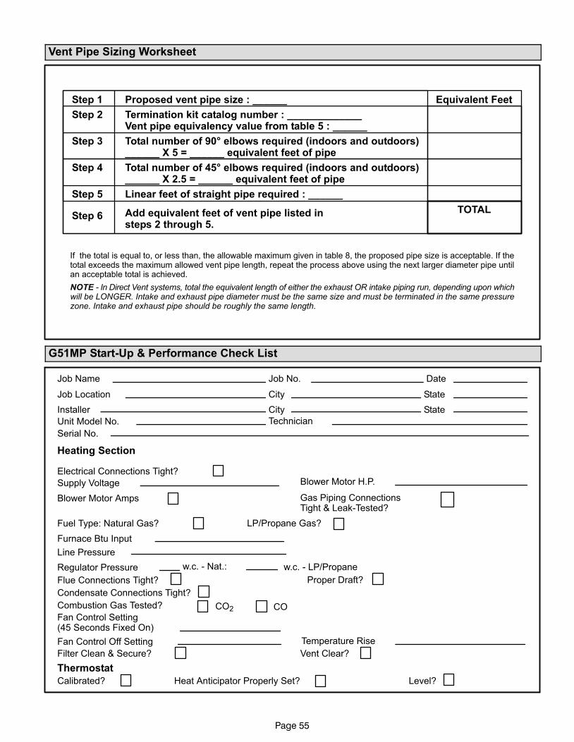
Page 55
Vent Pipe Sizing Worksheet
Proposed vent pipe size : ______
Termination kit catalog number : _____________Vent pipe equivalency value from table 5 : ______
Total number of 90° elbows required (indoors and outdoors)______ X 5 = ______ equivalent feet of pipe
Total number of 45° elbows required (indoors and outdoors)______ X 2.5 = ______ equivalent feet of pipe
Linear feet of straight pipe required : ______
Add equivalent feet of vent pipe listed insteps 2 through 5.
Step 1
Step 2
Step 3
Step 4
Step 5
Step 6
If the total is equal to, or less than, the allowable maximum given in table 8, the proposed pipe size is acceptable. If thetotal exceeds the maximum allowed vent pipe length, repeat the process above using the next larger diameter pipe untilan acceptable total is achieved.
NOTE − In Direct Vent systems, total the equivalent length of either the exhaust OR intake piping run, depending upon whichwill be LONGER. Intake and exhaust pipe diameter must be the same size and must be terminated in the same pressurezone. Intake and exhaust pipe should be roughly the same length.
Equivalent Feet
TOTAL
G51MP Start−Up & Performance Check List
w.c. − LP/Propane
Filter Clean & Secure?
Supply Voltage
Electrical Connections Tight?
Job Name
Job Location
Installer
Unit Model No.
Furnace Btu Input
Line Pressure
Job No.
City
City
Serial No.
Date
State
Technician
Flue Connections Tight?
Heating Section
Thermostat
Calibrated? Heat Anticipator Properly Set? Level?
Fuel Type: Natural Gas?
Blower Motor Amps
Blower Motor H.P.
Gas Piping ConnectionsTight & Leak−Tested?
Proper Draft?
Vent Clear?
State
Temperature RiseFan Control Off Setting
Fan Control Setting(45 Seconds Fixed On)
Regulator Pressure w.c. − Nat.:
LP/Propane Gas?
Combustion Gas Tested? CO2 CO
Condensate Connections Tight?
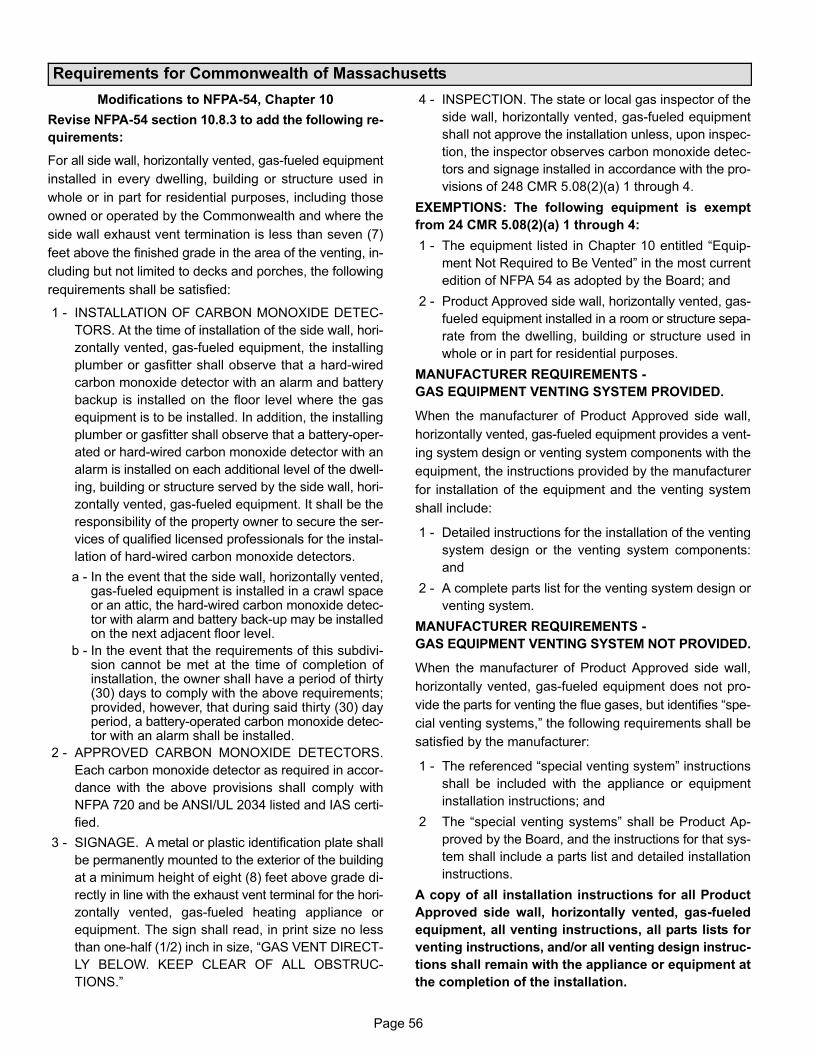
Page 56
Requirements for Commonwealth of Massachusetts
Modifications to NFPA−54, Chapter 10
Revise NFPA−54 section 10.8.3 to add the following re-
quirements:
For all side wall, horizontally vented, gas−fueled equipment
installed in every dwelling, building or structure used in
whole or in part for residential purposes, including those
owned or operated by the Commonwealth and where the
side wall exhaust vent termination is less than seven (7)
feet above the finished grade in the area of the venting, in-
cluding but not limited to decks and porches, the following
requirements shall be satisfied:
1 − INSTALLATION OF CARBON MONOXIDE DETEC-
TORS. At the time of installation of the side wall, hori-
zontally vented, gas−fueled equipment, the installing
plumber or gasfitter shall observe that a hard−wired
carbon monoxide detector with an alarm and battery
backup is installed on the floor level where the gas
equipment is to be installed. In addition, the installing
plumber or gasfitter shall observe that a battery−oper-
ated or hard−wired carbon monoxide detector with an
alarm is installed on each additional level of the dwell-
ing, building or structure served by the side wall, hori-
zontally vented, gas−fueled equipment. It shall be the
responsibility of the property owner to secure the ser-
vices of qualified licensed professionals for the instal-
lation of hard−wired carbon monoxide detectors.
a − In the event that the side wall, horizontally vented,gas−fueled equipment is installed in a crawl spaceor an attic, the hard−wired carbon monoxide detec-tor with alarm and battery back−up may be installedon the next adjacent floor level.
b − In the event that the requirements of this subdivi-sion cannot be met at the time of completion ofinstallation, the owner shall have a period of thirty(30) days to comply with the above requirements;provided, however, that during said thirty (30) dayperiod, a battery−operated carbon monoxide detec-tor with an alarm shall be installed.
2 − APPROVED CARBON MONOXIDE DETECTORS.
Each carbon monoxide detector as required in accor-
dance with the above provisions shall comply with
NFPA 720 and be ANSI/UL 2034 listed and IAS certi-
fied.
3 − SIGNAGE. A metal or plastic identification plate shall
be permanently mounted to the exterior of the building
at a minimum height of eight (8) feet above grade di-
rectly in line with the exhaust vent terminal for the hori-
zontally vented, gas−fueled heating appliance or
equipment. The sign shall read, in print size no less
than one−half (1/2) inch in size, �GAS VENT DIRECT-
LY BELOW. KEEP CLEAR OF ALL OBSTRUC-
TIONS."
4 − INSPECTION. The state or local gas inspector of the
side wall, horizontally vented, gas−fueled equipment
shall not approve the installation unless, upon inspec-
tion, the inspector observes carbon monoxide detec-
tors and signage installed in accordance with the pro-
visions of 248 CMR 5.08(2)(a) 1 through 4.
EXEMPTIONS: The following equipment is exempt
from 24 CMR 5.08(2)(a) 1 through 4:
1 − The equipment listed in Chapter 10 entitled �Equip-
ment Not Required to Be Vented" in the most current
edition of NFPA 54 as adopted by the Board; and
2 − Product Approved side wall, horizontally vented, gas−
fueled equipment installed in a room or structure sepa-
rate from the dwelling, building or structure used in
whole or in part for residential purposes.
MANUFACTURER REQUIREMENTS −
GAS EQUIPMENT VENTING SYSTEM PROVIDED.
When the manufacturer of Product Approved side wall,
horizontally vented, gas−fueled equipment provides a vent-
ing system design or venting system components with the
equipment, the instructions provided by the manufacturer
for installation of the equipment and the venting system
shall include:
1 − Detailed instructions for the installation of the venting
system design or the venting system components:
and
2 − A complete parts list for the venting system design or
venting system.
MANUFACTURER REQUIREMENTS −
GAS EQUIPMENT VENTING SYSTEM NOT PROVIDED.
When the manufacturer of Product Approved side wall,
horizontally vented, gas−fueled equipment does not pro-
vide the parts for venting the flue gases, but identifies �spe-
cial venting systems," the following requirements shall be
satisfied by the manufacturer:
1 − The referenced �special venting system" instructions
shall be included with the appliance or equipment
installation instructions; and
2 The �special venting systems" shall be Product Ap-
proved by the Board, and the instructions for that sys-
tem shall include a parts list and detailed installation
instructions.
A copy of all installation instructions for all Product
Approved side wall, horizontally vented, gas−fueled
equipment, all venting instructions, all parts lists for
venting instructions, and/or all venting design instruc-
tions shall remain with the appliance or equipment at
the completion of the installation.